JP4424372B2 - Actuator control device - Google Patents
Actuator control device Download PDFInfo
- Publication number
- JP4424372B2 JP4424372B2 JP2007130513A JP2007130513A JP4424372B2 JP 4424372 B2 JP4424372 B2 JP 4424372B2 JP 2007130513 A JP2007130513 A JP 2007130513A JP 2007130513 A JP2007130513 A JP 2007130513A JP 4424372 B2 JP4424372 B2 JP 4424372B2
- Authority
- JP
- Japan
- Prior art keywords
- maximum lift
- lift amount
- valve mechanism
- actuator
- variable valve
- Prior art date
- Legal status (The legal status is an assumption and is not a legal conclusion. Google has not performed a legal analysis and makes no representation as to the accuracy of the status listed.)
- Expired - Fee Related
Links
Images


Classifications
-
- F—MECHANICAL ENGINEERING; LIGHTING; HEATING; WEAPONS; BLASTING
- F02—COMBUSTION ENGINES; HOT-GAS OR COMBUSTION-PRODUCT ENGINE PLANTS
- F02D—CONTROLLING COMBUSTION ENGINES
- F02D13/00—Controlling the engine output power by varying inlet or exhaust valve operating characteristics, e.g. timing
- F02D13/02—Controlling the engine output power by varying inlet or exhaust valve operating characteristics, e.g. timing during engine operation
-
- F—MECHANICAL ENGINEERING; LIGHTING; HEATING; WEAPONS; BLASTING
- F01—MACHINES OR ENGINES IN GENERAL; ENGINE PLANTS IN GENERAL; STEAM ENGINES
- F01L—CYCLICALLY OPERATING VALVES FOR MACHINES OR ENGINES
- F01L1/00—Valve-gear or valve arrangements, e.g. lift-valve gear
- F01L1/34—Valve-gear or valve arrangements, e.g. lift-valve gear characterised by the provision of means for changing the timing of the valves without changing the duration of opening and without affecting the magnitude of the valve lift
-
- F—MECHANICAL ENGINEERING; LIGHTING; HEATING; WEAPONS; BLASTING
- F01—MACHINES OR ENGINES IN GENERAL; ENGINE PLANTS IN GENERAL; STEAM ENGINES
- F01L—CYCLICALLY OPERATING VALVES FOR MACHINES OR ENGINES
- F01L13/00—Modifications of valve-gear to facilitate reversing, braking, starting, changing compression ratio, or other specific operations
- F01L13/0015—Modifications of valve-gear to facilitate reversing, braking, starting, changing compression ratio, or other specific operations for optimising engine performances by modifying valve lift according to various working parameters, e.g. rotational speed, load, torque
-
- F—MECHANICAL ENGINEERING; LIGHTING; HEATING; WEAPONS; BLASTING
- F02—COMBUSTION ENGINES; HOT-GAS OR COMBUSTION-PRODUCT ENGINE PLANTS
- F02D—CONTROLLING COMBUSTION ENGINES
- F02D41/00—Electrical control of supply of combustible mixture or its constituents
- F02D41/0002—Controlling intake air
-
- F—MECHANICAL ENGINEERING; LIGHTING; HEATING; WEAPONS; BLASTING
- F02—COMBUSTION ENGINES; HOT-GAS OR COMBUSTION-PRODUCT ENGINE PLANTS
- F02D—CONTROLLING COMBUSTION ENGINES
- F02D41/00—Electrical control of supply of combustible mixture or its constituents
- F02D41/22—Safety or indicating devices for abnormal conditions
- F02D41/221—Safety or indicating devices for abnormal conditions relating to the failure of actuators or electrically driven elements
-
- F—MECHANICAL ENGINEERING; LIGHTING; HEATING; WEAPONS; BLASTING
- F01—MACHINES OR ENGINES IN GENERAL; ENGINE PLANTS IN GENERAL; STEAM ENGINES
- F01L—CYCLICALLY OPERATING VALVES FOR MACHINES OR ENGINES
- F01L2800/00—Methods of operation using a variable valve timing mechanism
-
- F—MECHANICAL ENGINEERING; LIGHTING; HEATING; WEAPONS; BLASTING
- F01—MACHINES OR ENGINES IN GENERAL; ENGINE PLANTS IN GENERAL; STEAM ENGINES
- F01L—CYCLICALLY OPERATING VALVES FOR MACHINES OR ENGINES
- F01L2800/00—Methods of operation using a variable valve timing mechanism
- F01L2800/11—Fault detection, diagnosis
-
- F—MECHANICAL ENGINEERING; LIGHTING; HEATING; WEAPONS; BLASTING
- F02—COMBUSTION ENGINES; HOT-GAS OR COMBUSTION-PRODUCT ENGINE PLANTS
- F02D—CONTROLLING COMBUSTION ENGINES
- F02D11/00—Arrangements for, or adaptations to, non-automatic engine control initiation means, e.g. operator initiated
- F02D11/06—Arrangements for, or adaptations to, non-automatic engine control initiation means, e.g. operator initiated characterised by non-mechanical control linkages, e.g. fluid control linkages or by control linkages with power drive or assistance
- F02D11/10—Arrangements for, or adaptations to, non-automatic engine control initiation means, e.g. operator initiated characterised by non-mechanical control linkages, e.g. fluid control linkages or by control linkages with power drive or assistance of the electric type
- F02D11/107—Safety-related aspects
-
- F—MECHANICAL ENGINEERING; LIGHTING; HEATING; WEAPONS; BLASTING
- F02—COMBUSTION ENGINES; HOT-GAS OR COMBUSTION-PRODUCT ENGINE PLANTS
- F02D—CONTROLLING COMBUSTION ENGINES
- F02D41/00—Electrical control of supply of combustible mixture or its constituents
- F02D41/0002—Controlling intake air
- F02D2041/001—Controlling intake air for engines with variable valve actuation
-
- F—MECHANICAL ENGINEERING; LIGHTING; HEATING; WEAPONS; BLASTING
- F02—COMBUSTION ENGINES; HOT-GAS OR COMBUSTION-PRODUCT ENGINE PLANTS
- F02D—CONTROLLING COMBUSTION ENGINES
- F02D35/00—Controlling engines, dependent on conditions exterior or interior to engines, not otherwise provided for
- F02D35/0007—Controlling engines, dependent on conditions exterior or interior to engines, not otherwise provided for using electrical feedback
-
- Y—GENERAL TAGGING OF NEW TECHNOLOGICAL DEVELOPMENTS; GENERAL TAGGING OF CROSS-SECTIONAL TECHNOLOGIES SPANNING OVER SEVERAL SECTIONS OF THE IPC; TECHNICAL SUBJECTS COVERED BY FORMER USPC CROSS-REFERENCE ART COLLECTIONS [XRACs] AND DIGESTS
- Y02—TECHNOLOGIES OR APPLICATIONS FOR MITIGATION OR ADAPTATION AGAINST CLIMATE CHANGE
- Y02T—CLIMATE CHANGE MITIGATION TECHNOLOGIES RELATED TO TRANSPORTATION
- Y02T10/00—Road transport of goods or passengers
- Y02T10/10—Internal combustion engine [ICE] based vehicles
- Y02T10/12—Improving ICE efficiencies
-
- Y—GENERAL TAGGING OF NEW TECHNOLOGICAL DEVELOPMENTS; GENERAL TAGGING OF CROSS-SECTIONAL TECHNOLOGIES SPANNING OVER SEVERAL SECTIONS OF THE IPC; TECHNICAL SUBJECTS COVERED BY FORMER USPC CROSS-REFERENCE ART COLLECTIONS [XRACs] AND DIGESTS
- Y02—TECHNOLOGIES OR APPLICATIONS FOR MITIGATION OR ADAPTATION AGAINST CLIMATE CHANGE
- Y02T—CLIMATE CHANGE MITIGATION TECHNOLOGIES RELATED TO TRANSPORTATION
- Y02T10/00—Road transport of goods or passengers
- Y02T10/10—Internal combustion engine [ICE] based vehicles
- Y02T10/40—Engine management systems
Description
この発明は、機関状態量を変更するためのアクチュエータと、同アクチュエータの実操作位置を検出するセンサとを備え、機関運転状態に基づき設定される目標操作位置に実操作位置を一致させるようにアクチュエータを制御するアクチュエータの制御装置に関する。 The present invention includes an actuator for changing an engine state quantity and a sensor for detecting an actual operation position of the actuator, and the actuator is configured to match the actual operation position with a target operation position set based on the engine operation state. The present invention relates to an actuator control apparatus for controlling the actuator.
例えば、特許文献1等に記載されるような可変動弁機構の制御装置では、吸気バルブの目標最大リフト量に対応した目標操作位置を機関運転状態に基づいて設定する一方、可変動弁機構の実操作位置をセンサにより検出し、その検出結果に基づいて実際の最大リフト量を求めるようにしている。そして、目標最大リフト量に実際の最大リフト量を一致させるように可変動弁機構の操作位置を制御するようにしている。
For example, in a control apparatus for a variable valve mechanism as described in
こうした可変動弁機構にあってその可動部に異物が噛み込んだり、劣化した潤滑油が同可動部に固着したりする等の要因により異常が生じると、内燃機関の運転状態に応じた最大リフト量の変更を行うことができなくなる。 In such a variable valve mechanism, if an abnormality occurs due to foreign matter being caught in the movable part, or deteriorated lubricating oil sticking to the movable part, the maximum lift according to the operating state of the internal combustion engine The amount cannot be changed.
そこで従来は、センサの検出結果に基づいて求められる実際の最大リフト量と目標最大リフト量との偏差が判定値以下となる状態が予め設定された期間継続するといった条件が満たされる場合に可変動弁機構が正常である旨判定する一方、同条件が満たされない場合には可変動弁機構が異常である旨判定するようにしている。
ところで、例えばアイドル運転時や定常運転時などのように目標最大リフト量が大きく変動しないときには、実際の最大リフト量も大きく変動することはない。この場合、実際には可変動弁機構の応答性が低下する等の異常が生じている場合であっても、実際の最大リフト量と目標最大リフト量との偏差が判定値を超えない状態が継続されることとなるため、従来の制御装置にあっては、可変動弁機構に異常が生じていない旨の判定、すなわち正常である旨の誤判定がなされるといった問題が生じる。 By the way, when the target maximum lift amount does not fluctuate greatly, such as during idle operation or steady operation, the actual maximum lift amount does not fluctuate greatly. In this case, even when an abnormality such as a decrease in the responsiveness of the variable valve mechanism actually occurs, there is a state where the deviation between the actual maximum lift amount and the target maximum lift amount does not exceed the judgment value. Therefore, in the conventional control device, there is a problem that a determination that no abnormality has occurred in the variable valve mechanism, that is, an erroneous determination that it is normal is made.
なお、ここでは、機関バルブの最大リフト量などのバルブ特性を変更するための可変動弁機構について説明したが、こうした不都合は同構成に限らず、機関運転状態に基づき設定される目標操作位置に前記実操作位置を一致させることにより、機関状態量を変更するためのアクチュエータを制御する制御装置においても概ね共通して発生し得る。 Although the variable valve mechanism for changing the valve characteristics such as the maximum lift amount of the engine valve has been described here, such inconvenience is not limited to the same configuration, and the target operation position set based on the engine operating state is not limited. By making the actual operation positions coincide with each other, it can also occur in common in the control device that controls the actuator for changing the engine state quantity.
この発明は、こうした実情に鑑みてなされたものであり、その目的は、アクチュエータの正常判定の精度を向上させることのできるアクチュエータの制御装置を提供することにある。 The present invention has been made in view of such circumstances, and an object of the present invention is to provide an actuator control device capable of improving the accuracy of normal determination of the actuator.
以下、上記課題を解決するための手段及びその作用効果について記載する。
請求項1に記載の発明は、機関状態量を変更するためのアクチュエータと、同アクチュエータの実操作位置を検出するセンサとを備え、機関運転状態に基づき設定される目標操作位置に前記実操作位置を一致させるように前記アクチュエータを制御するアクチュエータの制御装置であって、前記機関運転状態に基づき設定される目標操作位置と前記実操作位置との偏差の小さい状態が所定期間にわたって継続し、且つ、同所定期間における前記目標操作位置の変化量が所定値以上であることを条件に前記アクチュエータの操作状態が正常である旨判定する判定手段を備えることをその要旨とする。
Hereinafter, means for solving the above-described problems and the effects thereof will be described.
The invention according to
同構成によれば、アクチュエータの目標操作位置と実操作位置との絶対偏差の小さい状態が所定期間にわたって継続された場合であっても、同所定期間内における目標操作位置の変化量、すなわち同所定期間内における目標操作位置の最大値と最小値との絶対偏差が所定値よりも小さい場合には、アクチュエータの操作状態が正常である旨判定されることがない。すなわち、目標操作位置の変化量が小さいために、アクチュエータの応答性が低下している場合であってもその目標操作位置と実操作位置との絶対偏差が必然的に小さくなる場合には、こうした判定が保留されることとなる。このため、アクチュエータの正常判定の精度を向上させることができる。 According to this configuration, even when a state where the absolute deviation between the target operation position of the actuator and the actual operation position is small is continued for a predetermined period, the amount of change in the target operation position within the predetermined period, that is, When the absolute deviation between the maximum value and the minimum value of the target operation position within the period is smaller than the predetermined value, it is not determined that the operation state of the actuator is normal. That is, if the absolute deviation between the target operation position and the actual operation position is inevitably small even when the response of the actuator is low because the amount of change in the target operation position is small, The determination will be suspended. For this reason, the accuracy of the normal determination of the actuator can be improved.
請求項2に記載の発明は、請求項1に記載のアクチュエータの制御装置において、前記アクチュエータは、吸気バルブの最大リフト量を変更する可変動弁機構であることをその要旨とする。 The gist of the second aspect of the present invention is that the actuator is a variable valve mechanism that changes the maximum lift amount of the intake valve in the actuator control apparatus according to the first aspect.
例えば、吸気バルブの最大リフト量を変更するための可変動弁機構を備えた内燃機関にあっては、アイドル運転状態や定常運転状態が長期間継続するような場合は、吸気バルブの最大リフト量が所定値に設定されたままとなり、長期間にわたって目標最大リフト量の変更がなされないことがある。したがって、単に目標最大リフト量と実際の最大リフト量との絶対偏差が小さいことをもって可変動弁機構の操作状態が正常である旨判定するようにした場合には、実際には可変動弁機構の応答性が低下する等の異常が生じていても、目標最大リフト量と実際の最大リフト量との絶対偏差の小さい状態が所定期間にわたって継続されることがあり、可変動弁機構が正常に動作する旨の誤判定がなされることがある。 For example, in the case of an internal combustion engine having a variable valve mechanism for changing the maximum lift amount of the intake valve, the maximum lift amount of the intake valve is maintained when the idle operation state or the steady operation state continues for a long period of time. May remain set to a predetermined value, and the target maximum lift amount may not be changed over a long period of time. Therefore, when it is determined that the operating state of the variable valve mechanism is normal based on the fact that the absolute deviation between the target maximum lift amount and the actual maximum lift amount is small, the variable valve mechanism actually Even if an abnormality such as a decrease in responsiveness occurs, a state in which the absolute deviation between the target maximum lift amount and the actual maximum lift amount is small may continue for a predetermined period, and the variable valve mechanism operates normally. An erroneous determination may be made.
この点、上記構成によれば、目標最大リフト量の変化量が小さいことによって可変動弁機構が正常であるか否かを判別することができないときには、こうした判定が保留されることとなる。このため、可変動弁機構の正常判定の精度を向上させることができる。 In this regard, according to the above configuration, such determination is suspended when it is not possible to determine whether or not the variable valve mechanism is normal because the amount of change in the target maximum lift amount is small. For this reason, the accuracy of the normal determination of the variable valve mechanism can be improved.
以下、この発明を、車載内燃機関の機関状態量として吸気バルブの最大リフト量を変更する可変動弁機構の制御装置に適用した一実施の形態について、図1〜図3を参照して説明する。 Hereinafter, an embodiment in which the present invention is applied to a control device for a variable valve mechanism that changes a maximum lift amount of an intake valve as an engine state quantity of a vehicle-mounted internal combustion engine will be described with reference to FIGS. .
図1は、この実施の形態にかかる可変動弁機構の制御装置及びその制御対象である可変動弁機構の関係を示したブロック図である。同図1に示されるように、内燃機関1には、吸気バルブの最大リフト量を変更する可変動弁機構2が設けられている。この可変動弁機構2には、同機構2の実操作位置を検出するための位置センサ21が設けられるとともに、この位置センサ21の検出結果は後述する電子制御装置5に取り込まれる。なお、この可変動弁機構2はバッテリ3から供給される電力によって駆動されるモータによりその操作位置が変更され、その操作位置に応じて吸気バルブの最大リフト量が変更される。
FIG. 1 is a block diagram showing the relationship between a control apparatus for a variable valve mechanism according to this embodiment and a variable valve mechanism that is a control target thereof. As shown in FIG. 1, the
一方、この可変動弁機構2が搭載される内燃機関1には、車両のアクセルペダルの開度を検出するアクセルセンサや、内燃機関のクランクシャフトの回転位相を検出するクランク角センサ等、機関の運転状態を検出する各種センサ4が設けられており、これら各種センサ4の検出結果は電子制御装置5に取り込まれる。
On the other hand, the
電子制御装置5は、機関運転状態に基づいて吸気バルブの目標最大リフト量VLtを設定するとともに、上述した位置センサ21の検出結果に基づいて可変動弁機構2の実操作位置、すなわち吸気バルブの実際の最大リフト量VLcを検出する。そして、目標最大リフト量VLtに実際の最大リフト量VLcを一致させるように可変動弁機構2を駆動してその操作位置をフィードバック制御するようにしている。
The
ところで、こうした可変動弁機構2にあってその可動部に異物が噛み込んだり、劣化した潤滑油が同可動部に固着したりする等の要因により異常が生じると、機関運転状態に応じた吸気バルブの最大リフト量の変更を行うことができなくなる。このため、可変動弁機構2の操作状態が正常であるか否かを精度良く判定することが重要となる。
By the way, if an abnormality occurs in such a
そこで、電子制御装置5の操作状態判定部51では、目標最大リフト量VLtと実際の最大リフト量VLcとの絶対偏差の小さい状態が所定期間T1にわたって継続し、且つ、同所定期間T1における目標最大リフト量VLtの変化量が所定値B以上であることを条件に可変動弁機構2の操作状態が正常である旨判定するようにしている。
Therefore, in the operation
図2は、電子制御装置5を通じて実行される上述した可変動弁機構2の操作状態の正常判定を行う際の具体的な処理手順を示したフローチャートである。なおこの一連の処理は、電子制御装置5によって所定の周期をもって繰り返し実行される。
FIG. 2 is a flowchart showing a specific processing procedure for performing normal determination of the operation state of the
同図2に示されるように、この一連の処理では、まず、可変動弁機構2の操作状態の正常判定を行う上での前提条件が成立しているか否かが判定される(ステップS1)。
ここでは、例えば
・機関冷却水の温度がマイナス20度以上である。
・機関回転速度が300rpm以上である。
・バッテリ3の電圧が8V以上である。
As shown in FIG. 2, in this series of processing, first, it is determined whether or not a precondition for performing normal determination of the operation state of the
Here, for example, the temperature of the engine cooling water is minus 20 degrees or more.
-The engine speed is 300 rpm or more.
-The voltage of the
といった各条件の論理積が真であるときに前提条件が成立しているものとみなされる。すなわち、極低温時や機関始動時のように可変動弁機構2の可動部におけるフリクションが高いときや、可変動弁機構2に供給される電力が不足しているときのように、外的要因によって可変動弁機構2の応答性が低下しているときには可変動弁機構2の操作状態が正常か否かを精度良く判定することができないとして正常判定を行わないこととしている。そして上記判定の結果、上記前提条件が成立していない場合(ステップS1:「NO」)には、この処理を一旦終了する。
It is considered that the precondition is satisfied when the logical product of these conditions is true. That is, an external factor such as when the friction in the movable part of the
一方、上記前提条件が成立している場合(ステップS1:「YES」)には、次に、そのときの目標最大リフト量VLtと実際の最大リフト量VLcとの絶対偏差(=|VLt−VLc|)が予め設定される所定値Aよりも小さいか否かが判定される(ステップS2)。そしてこの結果、同絶対偏差が所定値A以上である場合(ステップS2:「NO」)には、継続期間Tを「0」にリセットして(ステップS3)、この処理を一旦終了する。なおここで、この継続期間Tとは、目標最大リフト量VLtと実際の最大リフト量VLcとの絶対偏差が継続して所定値Aよりも小さい状態となっている期間に相当する。 On the other hand, if the above precondition is satisfied (step S1: “YES”), then the absolute deviation (= | VLt−VLc) between the target maximum lift amount VLt and the actual maximum lift amount VLc at that time. It is determined whether or not | is smaller than a predetermined value A set in advance (step S2). As a result, when the absolute deviation is equal to or greater than the predetermined value A (step S2: “NO”), the duration T is reset to “0” (step S3), and this process is temporarily ended. Here, the continuation period T corresponds to a period in which the absolute deviation between the target maximum lift amount VLt and the actual maximum lift amount VLc is continuously smaller than the predetermined value A.
一方、目標最大リフト量VLtと実際の最大リフト量VLcとの偏差が所定値Aよりも小さい場合(ステップS2:「YES」)には、上記継続期間Tをカウントアップする(ステップS4)。そして、次に、この継続期間Tが所定期間T1以上となったか否かが判定される(ステップS5)。そしてこの結果、継続期間Tが所定期間T1未満である場合(ステップS5:「NO」)には、この処理を一旦終了する。 On the other hand, when the deviation between the target maximum lift amount VLt and the actual maximum lift amount VLc is smaller than the predetermined value A (step S2: “YES”), the continuation period T is counted up (step S4). Next, it is determined whether or not the continuation period T is equal to or longer than the predetermined period T1 (step S5). As a result, when the continuation period T is less than the predetermined period T1 (step S5: “NO”), this process is temporarily ended.
一方、継続期間Tが所定期間T1以上である場合(ステップS5:「YES」)には、次に、この継続期間Tにおける目標最大リフト量VLtの最大値VLtmaxと最小値VLtminとの偏差(=VLtmax−VLtmin)が所定値B(B>A)以上であるか否かが判定される(ステップS6)。そしてこの結果、同偏差が所定値B未満である場合(ステップS6:「NO」)には、この処理を一旦終了する。すなわち、目標最大リフト量VLtと実際の最大リフト量VLcとの偏差が小さい状態が所定期間T1にわたって継続された場合であっても、この継続期間Tにおける目標最大リフト量VLtの変化量が小さい場合には、可変動弁機構2の操作状態が正常か否かを精度良く判定することができないとして正常である旨判定されない。
On the other hand, when the continuation period T is equal to or longer than the predetermined period T1 (step S5: “YES”), next, the deviation between the maximum value VLtmax and the minimum value VLtmin of the target maximum lift amount VLt in the continuation period T (= It is determined whether or not (VLtmax−VLtmin) is equal to or greater than a predetermined value B (B> A) (step S6). As a result, when the deviation is less than the predetermined value B (step S6: “NO”), this process is temporarily ended. That is, even when the state where the deviation between the target maximum lift amount VLt and the actual maximum lift amount VLc is small is continued for a predetermined period T1, the amount of change in the target maximum lift amount VLt during this continuous period T is small. Therefore, it is not determined that the operating state of the
一方、同偏差が所定値B以上である場合(ステップS6:「YES」)には、可変動弁機構2の状態が正常である旨判定して(ステップS7)、この処理を一旦終了する。
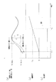
次に、図3及び図4のタイミングチャートを参照して図2に示される一連の処理が実行された場合における吸気バルブの目標最大リフト量VLt及び実際の最大リフト量VLcの推移、継続期間Tの推移、並びに可変動弁機構2の操作状態が正常か否かを示す判定結果の推移について説明する。
On the other hand, when the deviation is equal to or larger than the predetermined value B (step S6: “YES”), it is determined that the state of the
Next, the transition of the target maximum lift amount VLt and the actual maximum lift amount VLc of the intake valve and the duration T when the series of processing shown in FIG. And the transition of the determination result indicating whether the operation state of the
同図3(a)に示されるように、時刻t1において目標最大リフト量VLtと実際の最大リフト量VLcとの偏差(=|VLt−VLc|)が所定値A未満になると、図3(b)に示されるように、継続期間Tがカウントアップされるようになる。そして、時刻t2において継続期間Tが所定期間T1に達すると、同継続期間(時刻t1から時刻t2まで)における目標最大リフト量VLtの最大値VLtmaxと最小値VLtminとの偏差C(=VLtmax−VLtmin)が所定値B以上であるため、図3(c)に示されるように、可変動弁機構2の操作状態が正常である旨判定される。
As shown in FIG. 3A, when the deviation (= | VLt−VLc |) between the target maximum lift amount VLt and the actual maximum lift amount VLc becomes less than a predetermined value A at time t1, FIG. ), The duration T is counted up. When the duration T reaches the predetermined duration T1 at time t2, the deviation C (= VLtmax−VLtmin) between the maximum value VLtmax and the minimum value VLtmin of the target maximum lift amount VLt in the same duration (from time t1 to time t2). ) Is equal to or greater than the predetermined value B, it is determined that the operating state of the
一方、図4(a)に示されるように、時刻t1において目標最大リフト量VLtと実際の最大リフト量VLcとの偏差(=|VLt−VLc|)が所定値A未満になると、図4(b)に示されるように、継続期間Tがカウントアップされるようになる。そして、時刻t2において継続期間Tが所定期間T1に達すると、同継続期間(時刻t1から時刻t2まで)における目標最大リフト量VLtの最大値VLtmaxと最小値VLtminとの偏差D(=VLtmax−VLtmin)が所定値B未満であるため、図3(c)に示されるように、可変動弁機構2の操作状態が正常である旨判定されない、すなわち判定が保留されることとなる。
On the other hand, as shown in FIG. 4A, when the deviation (= | VLt−VLc |) between the target maximum lift amount VLt and the actual maximum lift amount VLc becomes less than a predetermined value A at time t1, As shown in b), the duration T is counted up. When the continuation period T reaches the predetermined period T1 at time t2, the deviation D (= VLtmax−VLtmin) between the maximum value VLtmax and the minimum value VLtmin of the target maximum lift amount VLt in the continuation period (from time t1 to time t2). ) Is less than the predetermined value B, as shown in FIG. 3C, it is not determined that the operation state of the
以上説明したこの実施の形態にかかる可変動弁機構の制御装置によれば、以下に列記するような効果が得られるようになる。
(1)内燃機関1にあっては、アイドル運転状態や定常運転状態が長期間継続するような場合は、吸気バルブの最大リフト量が所定値に設定されたままとなり、長期間にわたって目標最大リフト量VLtの変更がなされないことがある。したがって、単に目標最大リフト量VLtと実際の最大リフト量VLcとの絶対偏差(=|VLt−VLc|)が小さいことをもって可変動弁機構2の操作状態が正常である旨判定されるようにした場合には、実際には可変動弁機構2の応答性が低下する等の異常が生じていても、目標最大リフト量VLtと実際の最大リフト量VLcとの絶対偏差の小さい状態が所定期間T1にわたって継続されることがあり、可変動弁機構2が正常に動作する旨の誤判定がなされることがある。この点、上記実施の形態では、目標最大リフト量VLtと実際の最大リフト量VLcとの絶対偏差の小さい状態が所定期間T1にわたって継続し、且つ、同所定期間T1における目標最大リフト量VLtの変化量が所定値以上であることを条件に可変動弁機構2の操作状態が正常である旨判定する操作状態判定部51を備えることとした。これにより、目標最大リフト量VLtと実際の最大リフト量VLcとの絶対偏差の小さい状態が所定期間T1にわたって継続された場合であっても、同所定期間T1内における目標最大リフト量VLtの最大値VLtmaxと最小値VLtminとの偏差(=VLtmax−VLtmin)が所定値B未満である場合には、可変動弁機構2の操作状態が正常である旨判定されることがない。すなわち、目標最大リフト量VLtの変化量が小さいために、可変動弁機構2の応答性が低下している場合であってもその目標最大リフト量VLtと実際の最大リフト量VLcとの絶対偏差が必然的に小さくなる場合には、こうした判定が保留されることとなる。このため、可変動弁機構2の正常判定の精度を向上させることができる。
According to the control apparatus for the variable valve mechanism according to this embodiment described above, the effects listed below can be obtained.
(1) In the
なお、この発明にかかるアクチュエータの制御装置は、上記実施の形態にて例示した構成に限定されるものではなく、これを適宜変更した例えば次のような形態として実施することもできる。 The actuator control device according to the present invention is not limited to the configuration exemplified in the above-described embodiment, and can be implemented as, for example, the following forms appropriately modified.
・上記実施の形態では、電動式の可変動弁機構について例示したが、これを油圧式の可変動弁機構にしてもよい。
・上記実施の形態では、吸気バルブの最大リフト量を変更する可変動弁機構について例示したが、この発明は、機関状態量として最大リフト量に限らず、開弁時期、閉弁時期、開閉弁時期、或いはそれらの組み合わせ等、それ以外のバルブ特性を機関状態量として変更するアクチュエータ、更には吸気バルブのバルブ特性に限らず、排気バルブのバルブ特性を変更するためのアクチュエータの制御装置として具現化することもできる。
In the above-described embodiment, the electric variable valve mechanism is illustrated, but this may be a hydraulic variable valve mechanism.
In the above embodiment, the variable valve mechanism that changes the maximum lift amount of the intake valve has been exemplified. However, the present invention is not limited to the maximum lift amount as the engine state amount, but the valve opening timing, the valve closing timing, It is realized as an actuator that changes other valve characteristics such as timing or combination thereof as engine state quantity, and also as an actuator control device for changing valve characteristics of exhaust valves, not limited to valve characteristics of intake valves You can also
・また、他に例えば、スロットルバルブの開度を機関状態量としてこれを変更するモータの制御装置に本発明を適用することもできる。この場合、スロットルバルブの目標開度と実際の開度との偏差の小さい状態が所定期間にわたって継続し、且つ、同所定期間における目標開度の変化量が所定値以上であることを条件にモータの操作状態が正常である旨判定するようにすればよい。 In addition, for example, the present invention can be applied to a motor control device that changes the opening of a throttle valve as an engine state quantity. In this case, the motor is on condition that the state where the deviation between the target opening of the throttle valve and the actual opening is small continues for a predetermined period, and the change amount of the target opening in the predetermined period is equal to or greater than a predetermined value. It may be determined that the operation state is normal.
1…内燃機関、2…可変動弁機構、21…位置センサ、3…バッテリ、4…各種センサ、5…電子制御装置、51…操作状態判定部。
DESCRIPTION OF
Claims (2)
前記機関運転状態に基づき設定される目標操作位置と前記実操作位置との偏差の小さい状態が所定期間にわたって継続し、且つ、同所定期間における前記目標操作位置の変化量が所定値以上であることを条件に前記アクチュエータの操作状態が正常である旨判定する判定手段を備える
ことを特徴とするアクチュエータの制御装置。 An actuator for changing the engine state quantity and a sensor for detecting the actual operation position of the actuator are provided, and the actuator is controlled so that the actual operation position matches the target operation position set based on the engine operation state A control device for the actuator,
A state in which the deviation between the target operation position set based on the engine operating state and the actual operation position is small continues for a predetermined period, and the change amount of the target operation position in the predetermined period is equal to or greater than a predetermined value. An actuator control apparatus comprising: a determination unit that determines that the operation state of the actuator is normal on the condition of
前記アクチュエータは、吸気バルブの最大リフト量を変更する可変動弁機構である
ことを特徴とするアクチュエータの制御装置。 The actuator control device according to claim 1,
The actuator is a variable valve mechanism that changes a maximum lift amount of the intake valve.
Priority Applications (2)
| Application Number | Priority Date | Filing Date | Title |
|---|---|---|---|
| JP2007130513A JP4424372B2 (en) | 2007-05-16 | 2007-05-16 | Actuator control device |
| US12/122,302 US7730860B2 (en) | 2007-05-16 | 2008-05-16 | Actuator control apparatus and method |
Applications Claiming Priority (1)
| Application Number | Priority Date | Filing Date | Title |
|---|---|---|---|
| JP2007130513A JP4424372B2 (en) | 2007-05-16 | 2007-05-16 | Actuator control device |
Publications (2)
| Publication Number | Publication Date |
|---|---|
| JP2008286055A JP2008286055A (en) | 2008-11-27 |
| JP4424372B2 true JP4424372B2 (en) | 2010-03-03 |
Family
ID=40026252
Family Applications (1)
| Application Number | Title | Priority Date | Filing Date |
|---|---|---|---|
| JP2007130513A Expired - Fee Related JP4424372B2 (en) | 2007-05-16 | 2007-05-16 | Actuator control device |
Country Status (2)
| Country | Link |
|---|---|
| US (1) | US7730860B2 (en) |
| JP (1) | JP4424372B2 (en) |
Families Citing this family (2)
| Publication number | Priority date | Publication date | Assignee | Title |
|---|---|---|---|---|
| JP5393506B2 (en) * | 2010-01-27 | 2014-01-22 | 三菱重工業株式会社 | Control device and control method for control valve used in engine intake system |
| FR2995346B1 (en) * | 2012-09-12 | 2014-08-29 | Renault Sa | METHOD FOR DETECTING A FAILURE OF A DEVICE FOR OFFSETTING A CAMSHAFT |
Family Cites Families (8)
| Publication number | Priority date | Publication date | Assignee | Title |
|---|---|---|---|---|
| JP3822950B2 (en) | 1997-06-12 | 2006-09-20 | 株式会社日立製作所 | Self-diagnosis device for variable valve timing mechanism for internal combustion engine |
| JP3546651B2 (en) | 1997-07-30 | 2004-07-28 | トヨタ自動車株式会社 | Abnormality detection device for valve timing control device |
| JP3936818B2 (en) | 1999-03-31 | 2007-06-27 | 株式会社日立製作所 | Operating angle sensor failure determination device for variable valve operating device of internal combustion engine |
| JP3945117B2 (en) | 2000-03-09 | 2007-07-18 | トヨタ自動車株式会社 | Valve characteristic control device for internal combustion engine |
| US7343887B2 (en) | 2003-04-15 | 2008-03-18 | Toyota Jidosha Kabushiki Kaisha | Apparatus for abnormal diagnosis of variable valve timing mechanism |
| JP2005147115A (en) | 2003-11-18 | 2005-06-09 | Aisan Ind Co Ltd | Abnormality detection device for valve timing control device |
| JP2006037787A (en) | 2004-07-23 | 2006-02-09 | Toyota Motor Corp | Valve characteristic control device for internal combustion engine |
| JP2006070789A (en) | 2004-09-01 | 2006-03-16 | Fujitsu Ten Ltd | Variable valve timing device |
-
2007
- 2007-05-16 JP JP2007130513A patent/JP4424372B2/en not_active Expired - Fee Related
-
2008
- 2008-05-16 US US12/122,302 patent/US7730860B2/en not_active Expired - Fee Related
Also Published As
| Publication number | Publication date |
|---|---|
| JP2008286055A (en) | 2008-11-27 |
| US7730860B2 (en) | 2010-06-08 |
| US20080283007A1 (en) | 2008-11-20 |
Similar Documents
| Publication | Publication Date | Title |
|---|---|---|
| JP4889474B2 (en) | Variable valve control device for internal combustion engine | |
| US9139190B2 (en) | Apparatus for controlling vehicle and method for controlling vehicle | |
| US8181628B2 (en) | Throttle valve controller for internal combustion engine | |
| JP6742190B2 (en) | Engine fail-safe device | |
| US8116965B2 (en) | Apparatus for and method of controlling variable valve mechanism | |
| KR101108452B1 (en) | Controller of internal combustion engine | |
| JP4424372B2 (en) | Actuator control device | |
| JP2008297946A (en) | Control device for internal combustion engine | |
| KR101646386B1 (en) | Method and system for deecting malfunction of fastening bolt in cvvt | |
| GB2499893A (en) | Electronically controlled throttle defect diagnosis | |
| JP5874694B2 (en) | Diagnostic device for internal combustion engine | |
| JP2011256802A (en) | Variable valve system for internal combustion engine | |
| US20060174849A1 (en) | Apparatus and method for controlling variable valve actuation mechanism | |
| JP4826505B2 (en) | Control device for variable valve mechanism | |
| JP4092343B2 (en) | Self-diagnosis device for variable valve timing mechanism for internal combustion engine | |
| JP5935138B2 (en) | Control device for cam mechanism | |
| JP5678908B2 (en) | Throttle control system, throttle valve control device, throttle device, and throttle valve control method | |
| JP2009235959A (en) | Control device of actuator | |
| JP2008051111A (en) | Valve driving system for internal combustion engine | |
| JP4440566B2 (en) | Control of an internal combustion engine having a variable valve mechanism | |
| JP4069775B2 (en) | Abnormality determination device for internal combustion engine | |
| JP2008196335A (en) | Control device for variable valve train | |
| JP2008208764A (en) | Control device for variable valve system | |
| JP2009079513A (en) | Control device for internal combustion engine | |
| JP2008051061A (en) | Throttle valve controller and control method for internal combustion engine |
Legal Events
| Date | Code | Title | Description |
|---|---|---|---|
| A977 | Report on retrieval |
Free format text: JAPANESE INTERMEDIATE CODE: A971007 Effective date: 20090421 |
|
| A131 | Notification of reasons for refusal |
Free format text: JAPANESE INTERMEDIATE CODE: A131 Effective date: 20090428 |
|
| A521 | Written amendment |
Free format text: JAPANESE INTERMEDIATE CODE: A523 Effective date: 20090629 |
|
| TRDD | Decision of grant or rejection written | ||
| A01 | Written decision to grant a patent or to grant a registration (utility model) |
Free format text: JAPANESE INTERMEDIATE CODE: A01 Effective date: 20091117 |
|
| A01 | Written decision to grant a patent or to grant a registration (utility model) |
Free format text: JAPANESE INTERMEDIATE CODE: A01 |
|
| A61 | First payment of annual fees (during grant procedure) |
Free format text: JAPANESE INTERMEDIATE CODE: A61 Effective date: 20091130 |
|
| R151 | Written notification of patent or utility model registration |
Ref document number: 4424372 Country of ref document: JP Free format text: JAPANESE INTERMEDIATE CODE: R151 |
|
| FPAY | Renewal fee payment (event date is renewal date of database) |
Free format text: PAYMENT UNTIL: 20121218 Year of fee payment: 3 |
|
| FPAY | Renewal fee payment (event date is renewal date of database) |
Free format text: PAYMENT UNTIL: 20131218 Year of fee payment: 4 |
|
| LAPS | Cancellation because of no payment of annual fees |