JP4420220B2 - Grain discharger - Google Patents
Grain discharger Download PDFInfo
- Publication number
- JP4420220B2 JP4420220B2 JP2004293263A JP2004293263A JP4420220B2 JP 4420220 B2 JP4420220 B2 JP 4420220B2 JP 2004293263 A JP2004293263 A JP 2004293263A JP 2004293263 A JP2004293263 A JP 2004293263A JP 4420220 B2 JP4420220 B2 JP 4420220B2
- Authority
- JP
- Japan
- Prior art keywords
- grain
- discharge
- clutch device
- tension
- engine
- Prior art date
- Legal status (The legal status is an assumption and is not a legal conclusion. Google has not performed a legal analysis and makes no representation as to the accuracy of the status listed.)
- Expired - Fee Related
Links
- 238000007599 discharging Methods 0.000 claims description 27
- 238000005286 illumination Methods 0.000 claims description 22
- 230000005540 biological transmission Effects 0.000 claims description 8
- 235000013339 cereals Nutrition 0.000 description 118
- 238000001514 detection method Methods 0.000 description 9
- 238000003306 harvesting Methods 0.000 description 8
- 230000032258 transport Effects 0.000 description 8
- 230000008602 contraction Effects 0.000 description 5
- 238000010586 diagram Methods 0.000 description 3
- 239000007858 starting material Substances 0.000 description 3
- 239000010902 straw Substances 0.000 description 3
- 238000003801 milling Methods 0.000 description 2
- 241000196324 Embryophyta Species 0.000 description 1
- 239000004464 cereal grain Substances 0.000 description 1
- 230000006870 function Effects 0.000 description 1
- 238000005360 mashing Methods 0.000 description 1
- 239000000463 material Substances 0.000 description 1
- 230000002093 peripheral effect Effects 0.000 description 1
- 238000005096 rolling process Methods 0.000 description 1
- 239000004071 soot Substances 0.000 description 1
- 229920003002 synthetic resin Polymers 0.000 description 1
- 239000000057 synthetic resin Substances 0.000 description 1
Images



Landscapes
- Threshing Machine Elements (AREA)
Description
本発明は、圃場で穀類の収穫作業を行うコンバインの穀粒排出装置に関する。 The present invention relates to a combine grain discharging apparatus for harvesting grains in a field.
コンバインは、走行クローラを有する走行装置と走行フレームの前方側に植立穀稈を分草した後、植立穀稈を引き起こし、植立穀稈を刈り取る刈取装置と、刈り取られた穀稈を挟持して後方に搬送する供給搬送装置と、穀稈を脱穀、選別する脱穀装置と、脱穀装置で脱穀選別された穀粒を一時貯溜するグレンタンクと、グレンタンク内の穀粒をコンバインの外部に排出する穀粒排出装置等を備えている。 A combine harvester with a traveling crawler and a front side of the traveling frame weeds the planted culm, then causes the planted culm to harvest and harvests the planted culm, and holds the harvested culm Supply and transport device that transports backward, threshing device for threshing and sorting cereals, a Glen tank that temporarily stores the grains threshed and sorted by the threshing device, and the grains in the Glen tank outside the combine Equipped with a grain discharging device for discharging.
従来のコンバインの穀粒排出装置の作動用スイッチを操作レバーの後方近傍に配置するにあたり、穀粒排出装置の作動用スイッチを最も高い操作レバーの上端よりも高い位置に配置した発明(特開2003−18912号公報)が開示されている。
上記従来のコンバインの穀粒排出装置の作動用スイッチを入りとしておいて、エンジンが停止している状態からエンジンを始動すると、不用意に籾が排穀オーガから排出する。 If the operation switch of the conventional combine grain discharging device is turned on and the engine is started from a state where the engine is stopped, the straw is inadvertently discharged from the grain auger.
本発明の課題は、穀粒排出装置の作動用スイッチを入りとなって、エンジンが停止している状態からエンジンを始動しても不用意に籾が排穀オーガから排出しない穀粒排出装置を提供することである。 An object of the present invention is to turn on a switch for operating a grain discharging device, and to remove a grain discharging device that does not inadvertently discharge straw from a grain auger even if the engine is started from a state where the engine is stopped. Is to provide.
本発明の上記課題は、次の構成により解決される。
すなわち、収穫した穀粒を一時的に貯蔵するグレンタンク(3)内の穀粒をエンジン動力により外部に排出するための穀粒排出手段(10)と、伝動用の無端ベルト(43)と、該無端ベルト(43)で駆動される穀粒排出手段(10)の入力用のプーリ(45)と、該無端ベルト(43)を押圧するテンションローラ(44b)を先端に備えた揺動自在のテンションアーム(44a)と、該テンションアーム(44a)作動用のテンションモータ(44)とを有し、テンションアーム(44a)が作動開始位置(A)から作動を開始してベルト(43)を押圧して該テンションアーム(44a)がプーリ(45)を駆動させる位置(B)に到達することで穀粒排出手段(10)を作動させる「入」と、テンションアーム(44a)を作動開始位置(A)に戻して穀粒排出手段(10)を停止させる「切」に切り換える排出クラッチ装置(12)と、前記テンションモータ(44)の入り切り操作を行う照光スイッチ(46)と、該照光スイッチ(46)の入りでテンションアーム(44a)が排出クラッチ装置(12)を「切」から「入」にするべく前記作動開始位置(A)から作動開始すると同時に点灯し、排出クラッチ装置(12)が作動している間は点灯状態を保ち、テンションアーム(44a)が再び排出クラッチ装置(12)を「切」にする作動開始位置(A)まで戻って停止し、排出クラッチ装置(12)が完全に切り操作されると初めて消灯する照光スイッチランプ(47)と、排出クラッチ装置(12)の入り後、設定時間が経過すると排出クラッチ装置(12)を切る排出モードを選択する排出モード選択スイッチ(53)と、照光スイッチランプ(47)の点灯時にはエンジンの作動を禁止し、テンションモータ(44)による排出クラッチ装置(12)の完全な切り操作の後で初めてエンジンの作動を可能にすると共に、排出モード選択スイッチ(53)が押されているときにエンジン回転数センサ(57)で検出したエンジン回転数に応じて前記設定時間を設定する制御装置(50)を備えたことを特徴とする穀粒排出装置である。
The above-described problems of the present invention are solved by the following configuration.
That is, the grain discharge means for exiting exhaust kernels of grain tank (3) in which to temporarily store the harvested grain in the external Ri by the engine power (10), an endless belt for power transmission (43 ), An input pulley ( 45 ) for the grain discharging means (10) driven by the endless belt (43), and a tension roller ( 44 b ) for pressing the endless belt (43). It has a movable tension arm ( 44a ) and a tension motor ( 44 ) for operating the tension arm ( 44a ) , and the tension arm ( 44a ) starts to operate from the operation start position (A), and the belt (43 ) To reach the position (B) where the tension arm (44a) drives the pulley (45) to activate the grain discharging means (10), and the tension arm (44a) And the operation starting position discharge switch to "OFF" to stop the grain discharge means (10) back to (A) a clutch device (12), the illumination switch for turning on and off operation of the tensioning motor (44) and (46) When the illumination switch ( 46 ) is turned on, the tension arm ( 44 a ) lights up at the same time as the operation start from the operation start position (A) to turn the discharge clutch device (12) from “OFF” to “ON”, and the discharge clutch during device (12) is operating maintaining the lighting state, the tension arm (44a) is discharged clutch device again (12) to stop I return to the operation starting position to the "oFF" (a), discharge clutch apparatus (12) when the Ru is completely cut operation for the first time off for illuminating the switch lamp (47), after entering the discharge clutch device (12), that the set time elapses discharge And the discharge mode selection switch for selecting the discharge mode off clutch device (12) (53), prohibits the operation of the lighting sometimes engine illuminated switch lamp (47), discharging a clutch device according to the tension motor (44) (12) together to enable the first engine operation after a full cut operation, the setting time in accordance with the engine rotational speed detected by the engine speed sensor (57) when the discharge mode selection switch (53) is pressed It is a grain discharging apparatus provided with the control apparatus ( 50 ) which sets up .
本発明によれば、キーオン(電源が入りでエンジンが始動していない状態)で、テンションローラ44bの位置が把握できる。また、テンションモータ44による排出クラッチ装置12の入り操作開始の後では、エンジンの作動を禁止し、またテンションモータ44による排出クラッチ装置12が完全に切れた後で初めてエンジンの作動が可能になるので、穀粒排出装置の安全性が確保できる。さらに排出クラッチ装置12の入り切りが照光スイッチランプ47の点灯・消灯で確認できオペレータに分かりやすくなる。
また、排出モード選択スイッチ53が押されているときにエンジン回転数センサ57で検出したエンジン回転数に応じて、穀粒排出の開始から停止までの時間を設定することで、グレンタンク3からの穀粒を排出するための穀粒排出手段10の回転数がエンジン回転数に比例するため、穀粒の排出量を一定にすることが可能となる。 According to the present invention, the position of the
Further, by setting the time from the start to the stop of grain discharge according to the engine speed detected by the
本発明の実施の形態について以下図面と共に説明する。
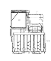
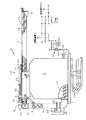
図1は本発明のコンバインの左側面図であり、図2はコンバインの正面図であり、図3はコンバインの背面図、図4はコンバインの排穀用の排穀オーガ部分の構造を説明する図である。
Embodiments of the present invention will be described below with reference to the drawings.
FIG. 1 is a left side view of the combine of the present invention, FIG. 2 is a front view of the combine, FIG. 3 is a rear view of the combine, and FIG. FIG.
図1〜図4を参照して、コンバインの機能の概略を説明する。
コンバインは、クローラ1を有する車台2の上に操縦室40を設けて、該操縦室40においてオペレータが操縦、操作して圃場に植立する穀稈を刈り取る刈取装置34、この刈り取られた穀稈を供給搬送装置で搬送した後、これを脱穀する脱穀装置37、脱穀された穀粒を収容するグレンタンク3、このグレンタンク3の底部に設けた底部螺旋10(図4)によって後方へ排出される穀粒をコンバインの外部へ搬送する排穀オーガ5などから構成される。
The outline of the function of a combine is demonstrated with reference to FIGS.
The combine is provided with a
排穀オーガ5は、底部螺旋10の後端部に連接されて上方へ穀粒を搬送する揚穀筒4および揚穀筒4に連接され、横方向へ穀粒を搬送する固定搬送筒6及び移動搬送筒7などからなる。移動搬送筒7の先端には排穀オーガ排出口9を備えている。
The
図1に示すコンバインは、車台2の下部にゴムなどの可撓性材料を素材として無端帯状に成型した左右一対のクローラ1を持ち、乾田はもちろんのこと、湿田においてもクローラ1が若干沈下するだけで自由に走行できる構成の走行装置を備え、車台2の前部には刈取装置34を搭載し、車台2の上部には図示しないエンジンならびにグレンタンク3、脱穀装置37、操縦室40を備えている。
The combine shown in FIG. 1 has a pair of left and
コンバインのグレンタンク3に貯留された穀粒はグレンタンク3の底部に設けられた底部螺旋10から排出される。該底部螺旋10は、図3に示すようにグレンタンク3の底部に軸装して設けられ、その始端側を機外の伝動軸11にクラッチ装置12を介して連結し、その終端側を揚穀筒4の下部まで延長して、内装している揚穀螺旋13の下端部に接続した構成からなっている。
The grain stored in the
そして、排穀オーガ5(図4)は、前記揚穀筒4の上部に上下方向へ昇降自由に接続する固定搬送筒6と、これに接続する移動搬送筒7とから構成されているが、以下、その構成を具体的に説明する。
And the cerealing auger 5 (FIG. 4) is comprised from the fixed
まず、固定搬送筒6は、図4に示すように、基部を前記揚穀筒4の上部に連結し、先端部を外方に延長して設け、その筒内には、始端部を前記揚穀螺旋13に接続した搬送螺旋14を内装して揚穀筒4から受け継いだ穀粒を搬送する構成である。
First, as shown in FIG. 4, the fixed
移動搬送筒7は、図4に示すように先端部に排穀オーガ排出口9を開口して設け、基部側を前記固定搬送筒6に摺動自由に連結している。また、伸縮螺旋15は図4に示すように移動搬送筒7内において、先端部を排穀オーガ排出口9の上方位置に軸受して後部を固定搬送筒6側に延長して前記搬送螺旋14の軸内に摺動自由に挿入した伝動軸16を軸架して設け、この伝動軸16に多数の螺旋単体を摺動自由に嵌合して相互の間隔を調節できるように構成している。
As shown in FIG. 4, the moving
また、図4に示すように、伸縮駆動装置23は揚穀筒4の上部位置に装備した伸縮用駆動モータ24に減速装置を介して螺旋軸25の基端部を連結しており、伸縮用駆動モータ24により螺旋軸25を強制駆動する構成である。そして、移動装置26は上記螺旋軸25の螺旋溝に係合している伝動ピンを介して、強制的に軸方向に移動するように設け、前記固定搬送筒6の基部側に一体的に連結して構成している。
Moreover, as shown in FIG. 4, the expansion /
なお、伸縮駆動装置23は、図4に示すように排穀オーガ5の最縮側と最伸張側とにそれぞれリミットセンサS1、S2を設け、前記移動装置26がリミットセンサS1またはリミットセンサS2に達すると伸縮用駆動モータ24を自動停止する構成である。
In addition, as shown in FIG. 4, the expansion /
また、移動搬送筒7の先端部の位置は種々変化し得るが、排穀オーガ5の先端部の位置はズーム式排穀オーガ5の長さの中間位置で排穀オーガ受け35に収納される場合が多い。
Further, although the position of the front end portion of the
なお、伸縮用駆動モータ24は、操縦室40の操作パネル(図示せず)に設けたスイッチ(伸縮スイッチ)のオン操作に基づいて、正転または逆転方向に駆動されて螺旋軸25を回転駆動する構成とし、螺旋軸25が正転すれば、係合している移動装置26を介して移動搬送筒7を伸張し、逆転すれば縮小方向に強制的に移動する構成としている。
The expansion /
このようにして、移動搬送筒7は固定搬送筒6に嵌合した状態で固定搬送筒6に沿って伸び縮みして、その先端部の排穀オーガ排出口9の位置を、排穀オーガ5の基部の揚穀筒4に対して、遠ざけたり、近づけたり調節して穀粒の落下位置を選択できる構成としている。
In this way, the moving
なお、図4において、昇降油圧シリンダ27は排穀オーガ5を昇降させ、排穀オーガ旋回モータ28はその回転軸に設けられた旋回ギア29にかみ合う揚穀筒4の外周部に設けられた駆動ギヤ30を介して揚穀筒4の旋回を行う。
In FIG. 4, the lifting
そして、支持ローラ31は図4に示すように移動搬送筒7の基部位置の下部に軸架して設けられ、固定搬送筒6の周面を転動しながら固定搬送筒6を支持する構成である。また、移動搬送筒7の基部位置の上部には案内車輪32が設けられ、該案内車輪32を案内する案内レール(図示せず)を固定搬送筒6の長手方向に沿って設けている。
As shown in FIG. 4, the
前述のごとく構成されたコンバインを植立穀稈の刈取作業をさせながら前進させると、植立穀稈は刈取装置34(図1)により刈り取られ、その後、脱穀装置37の始端部へと搬送され、フィードチェンで搬送されながら脱穀選別される。脱穀装置37で脱穀選別された穀粒はグレンタンク3内へ一時貯留され、該グレンタンク3内の穀粒が満杯になると、排穀オーガ受け35(図4)から排穀オーガ5を離脱させて、該排穀オーガ5からトラック等の荷台へと穀粒を排出する。
When the combine configured as described above is moved forward while the harvesting operation is being performed on the planted culm, the planted culm is harvested by the harvesting device 34 (FIG. 1), and then conveyed to the start end of the
このとき、排穀オーガ排出口9の位置がトラック等の荷台へ達しない長さであると、移動搬送筒7を伸ばして、より遠くに穀粒を排出できるようにする。また、移動搬送筒7を伸縮させて、穀粒をトラック荷台へ均一に排出するようにする。このようにして、グレンタンク3内の穀粒を排出し終えると、排穀オーガ5を再び排穀オーガ受け35へと収納する。
At this time, when the position of the grain
図4に示す移動搬送筒7の伸縮螺旋15は合成樹脂製の複数の螺旋単体からなっている。
The
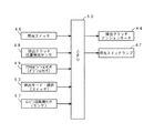
また、図5は本発明の実施の形態の排穀オーガ5の制御にかかわる制御装置50の簡単なブロック図であるが、排出クラッチ装置12の入り切り用の照光スイッチ46と排出クラッチ装置位置検出センサ48と排出モード選択スイッチ53とエンジンのアクセルポジションセンサ49とエンジン回転数センサ57が制御装置50の入力側に接続され、制御装置50の出力側には排出クラッチテンションモータ44と照光ランプスイッチ47などが設けられている。
FIG. 5 is a simple block diagram of the
グレンタンク3内の底部螺旋10にエンジン駆動力を伝達する排出クラッチ装置12(図4参照)の入切制御を本実施例ではテンションローラ44bを作動制御するテンションモータ44のオンオフを電力で行い、しかも排出クラッチ装置12の入切制御の様子を照光スイッチランプ47の点灯・消灯で確認できるようにした。
In the present embodiment, on / off control of the discharge clutch device 12 (see FIG. 4) that transmits the engine driving force to the
本実施例では図5に示すように、排出クラッチ装置12の入切スイッチとしてモーメンタリ式の照光スイッチ46を設け、オペレータが該照光スイッチ46をオンにすると、排出クラッチ装置12を入りとするためにテンションモータ44が作動を始めてテンションアーム44aが作動を開始する。
In this embodiment, as shown in FIG. 5, a momentary illumination switch 46 is provided as an on / off switch for the discharge
図6に示すように、このテンションアーム44aが作動を開始する位置(A)を排出クラッチ装置位置検出センサ48が検出して、この位置(A)を制御装置50内のメモリに記憶させておく。それと同時に照光スイッチランプ47が点灯となるのでテンションアーム44aが作動を始めたことをオペレータが確認できる。しかし、このときはテンションローラ44bが排出クラッチ装置12を作動する状態までテンションアーム44aが作動していない。
As shown in FIG. 6, the discharge clutch device position detection sensor 48 detects the position (A) at which the
その後、テンションアーム44aが所定量動くと、テンションローラ44bがベルト43を張ってプーリ45が作動し、排出クラッチ装置12が作動開始する。このときテンションモータ44がオフとなり、同時に、この排出クラッチ装置12が作動開始した位置(B)を排出クラッチ装置位置検出センサ48が検出し、この位置(B)を制御装置50内のメモリに記憶させておく。
Thereafter, when the
エンジンスタータキー(図示せず)を回して電源入りになると上記した照光スイッチランプ47が点灯となり、この照光スイッチランプ47が入り状態であれば、オペレータがエンジンスタータをエンジン始動側に回してもエンジンが始動しないようになっている。これは排出クラッチ装置12が入っているので、エンジンが始動するとグレンタンク3の底部螺旋10が回転してしまい、籾が不用意に排出されてしまうからである。
When the engine starter key (not shown) is turned to turn on the power, the
次に、照光スイッチ46をオフにするとテンションモータ44が作動を開始してテンションアーム44aが排出クラッチ装置12の入り位置、すなわちテンションローラ44bがベルト43を張って排出クラッチ装置12が作動する位置(B)から停止位置(A)に戻るとテンションモータ44が停止し、同時に照光スイッチランプ47も消灯する。
Next, when the illumination switch 46 is turned off, the
照光スイッチランプ47のオフで排出クラッチ装置12が完全に切り状態、すなわちテンションローラ44bがベルト43から完全に離れていることが分かるので、このとき排出クラッチ装置位置検出センサ48からの信号により制御装置50はエンジンの始動を可能な状態にする。
Since the discharge
このように照光スイッチランプ47の点灯・消灯は排出クラッチ装置位置検出センサ48の検出値に従って切り換わる構成として、排出クラッチ装置12のオンオフを照光スイッチランプ47の点灯・消灯で確認することができると同時にエンジンの始動が排出クラッチ装置12の完全に切りの状態のときにしかできないようにして、安全性を確保している。
In this way, the
前述のように、エンジンスタータキーを回して電源入りにしたとき、排出クラッチテンションモータ44がオンになっていると排出クラッチ装置12が入り状態となっているので、さらにエンジンキーを回してエンジンが作動開始してしまうと、穀粒を受け取る準備ができていない状態で排出オーガ5から穀粒が排出させる動作が始まる。このようなことがないように、本実施例の制御装置50は排出クラッチテンションモータ44がオンになっていると、エンジンキーをさらに回してもエンジンが作動しない制御を行う。
As described above, when the engine starter key is turned to turn on the power, if the discharge
上記排出クラッチ装置12の入り切り位置を検出する排出クラッチ装置位置検出センサ48は、それぞれ前記テンションローラ44bによるベルト43の作動位置と停止位置におけるテンションアーム44aの位置を検出するポテンショメータ(図示せず)を用いている。またポテンショメータに代えて前記テンションローラ44bによるベルト43の作動位置と停止位置におけるテンションアーム44aの揺動領域の近傍に配置したリミットスイッチ(図示せず)を用いても良い。
The discharge clutch device position detection sensor 48 that detects the on / off position of the discharge
また、排出クラッチ装置12の入り切り位置を検出する排出クラッチ装置位置検出センサ48の他の例として、排出クラッチテンションモータ44に内装されたリミットスイッチ(図示せず)を利用することもできる。このとき前記リミットスイッチは、排出クラッチ装置12を切とするときのテンションアーム44aの作動位置を検出する構成にすると、安価なリミットスイッチで排出クラッチ装置位置の検出ができる。
Further, as another example of the discharge clutch device position detection sensor 48 for detecting the on / off position of the discharge
また、このリミットスイッチで排出クラッチ装置12が完全に切れていることをテンションアーム44aの作動位置で検出すると、エンジン始動が可能になる構成とする。
Further, when the limit switch detects that the discharge
従来テンションアーム44aの両側の揺動領域の近傍に2個のリミットスイッチを配置して排出クラッチ装置12のテンションの有無を検知していた構成に比較して、排出クラッチテンションモータ44に内装されたリミットスイッチ一つだけを用いて排出クラッチ装置位置検出センサ48とするので、安価に構成可能になる。また排出クラッチ装置12の切り側のリミットスイッチを使用するため、排出クラッチ装置12が完全に切れた状態のときにのみ、照光スイッチランプ47が消灯し、エンジン始動が可能になるのでオペレータに分かりやすくなる。
Compared to the conventional configuration in which two limit switches are arranged in the vicinity of the swinging regions on both sides of the
本実施例の上記排出クラッチ装置12をテンションモータ44により作動させる機構を有し、かつその作動制御が可能なコンバインにおいて、グレンタンク3からの穀粒の排出モードを選択し得るスイッチ53を設けている。
A
そして前記穀粒排出モード選択スイッチ53を操作していないときは、照光スイッチ46を穀粒排出スイッチとして用いて、通常の穀粒連続排出を行うことができる。また穀粒排出モード選択スイッチ53が操作されているときは、穀粒排出開始から所定時間経過後、自動的に排穀オーガ5からの穀粒の排出を停止させる構成としている。
And when the said grain discharge
このような穀粒排出モード選択スイッチ53を設ける理由は、いわゆる袋取りといわれる穀粒の排出作業時の以下のような不具合を無くすためである。すなわち、いわゆる袋取作業は、操縦室40内のオペレータが穀粒排出操作をスタートさせ、一方でコンバインの外にいる補助者が排穀オーガ5の先端部の排出口9付近で袋を構えて穀粒を受けるが、この作業時に補助者の合図でオペレータが穀粒排出操作を実行するか、または停止するが、両者のタイミングが不一致なときには穀粒を袋からあふれさせるような不具合が生じることがある。
The reason for providing such a grain discharge
上記した問題点を解決すべく、穀粒排出モード選択スイッチ53をオンとすることにより、適量または少量ずつ穀粒を排出しながら穀粒排出作業を行うことができ、袋取り時の排出操作が非常に簡単になる。また、万一、いわゆる袋取り作業中であることをオペレータが忘れても、穀粒排出開始から所定時間経過後に自動的に排穀オーガ5からの穀粒の排出が停止されるので、袋から穀粒があふれ出ることはない。
In order to solve the above-mentioned problems, by turning on the grain discharge
また、排出モード選択スイッチ53が押されていない状態で排穀オーガ5から穀粒の排出実行中に、排出モード選択スイッチ53が押されることがある。
In addition, the discharge
このような場合には直ちに穀粒の排出を停止する制御を行うこととする。これは、穀粒排出時に誤操作があった可能性があるので、先ず緊急に穀粒排出を停止することで、無駄に穀粒が排出されないようにするためである。 In such a case, control to immediately stop the grain discharge is performed. This is because there is a possibility that there was an erroneous operation at the time of grain discharge, so that the grain discharge is first stopped urgently so that the grain is not discharged unnecessarily.
また、排出モード選択スイッチ53を押し忘れて、通常の穀粒排出を行うために照光スイッチ46を押して、いわゆる袋詰めを始めることがある。その袋詰めの最中にオペレータが排出モード選択スイッチ53の押し忘れに気がついて、あわてて排出モード選択スイッチ53を押すことがあるが、このようなときには、前記穀粒排出停止制御が実行されると、一旦、穀粒排出を停止して落ち着いて次に行うべき操作について考える余裕を与えることができる。
In addition, forgetting to press the discharge
また、前記穀粒排出停止制御の代わりに、穀粒排出速度を下げてゆっくり穀粒を排出させても良い。このときエンジンの回転数を、例えば定格回転から下げることで穀粒排出速度を下げることができる。 Moreover, you may discharge | release a grain slowly by lowering | hanging a grain discharge speed instead of the said grain discharge stop control. At this time, the grain discharge speed can be lowered by lowering the engine speed, for example, from the rated speed.
一方、排出モード選択スイッチ53をオンして穀粒排出操作実行中に当排出モード選択スイッチ53をオフにしても、開始時に設定された所定時間まで穀粒排出動作を続け、一旦始めた袋詰めを完了せる穀粒排出制御を行う。
On the other hand, even if the discharge
また、排出モード選択スイッチ53をオンして穀粒排出操作実行中に当排出モード選択スイッチ53をオフにしたとき、穀粒排出用の照光スイッチ46がオンであれば、そのまま連続的に通常の穀粒排出動作を続けて、照光スイッチ46がオフになると穀粒排出を停止するモードを採用しても良い。
Further, when the discharge
また、排出モード選択スイッチ53が押されているときに、コンバインのエンジン回転数をエンジン回転数センサ57で検出して、検出したエンジン回転数に応じて、穀粒排出の開始から停止までの時間を設定しても良い。これは、グレンタンク3からの穀粒を排出するためのグレンタンク底部螺旋10の回転数がエンジン回転数に比例するためであり、この制御で穀粒の排出量を一定にすることが可能となる。
Further, when the discharge
また、コンバインがエンジン回転数制御機構を有している場合に、排出モード選択スイッチ53が押されると、穀粒排出開始時は、エンジン回転数を通常の穀粒排出時(通常は定格エンジン回転数で穀粒排出を行う)より低めの所定回転数までエンジン回転数を下げても良い。
Further, when the combine has an engine speed control mechanism and the discharge
これは、いわゆる袋詰め作業のはじめに、補助者が袋詰めの心構えができていないことが考えられるので、いわゆる袋詰めのときは穀粒排出速度をゆっくりに調整して当作業を安全かつ簡単にするためである。 This is because the assistant may not be ready for bagging at the beginning of the so-called bagging operation, so when so-called bagging, adjust the grain discharge rate slowly and make this operation safe and easy. It is to do.
本発明は、コンバインなどのグレンタンクに適用できる。 The present invention can be applied to a grain tank such as a combine.
1 クローラ 2 車台
3 グレンタンク 4 揚穀筒
5 排穀オーガ 6 固定搬送筒
7 移動搬送筒 9 排穀オーガ排出口
10 底部螺旋 11 伝動軸
12 クラッチ装置 13 揚穀螺旋
14 搬送螺旋 15 伸縮螺旋
16 伝動軸 23 伸縮駆動装置
24 伸縮用駆動モータ 25 螺旋軸
26 移動装置 27 昇降油圧シリンダ
28 排穀オーガ旋回モータ 29 旋回ギア
30 駆動ギア 31 支持ローラ
32 案内車輪 34 刈取装置
35 排穀オーガ受け 37 脱穀装置
40 操縦室 43 ベルト
44 テンションモータ 44a テンションアーム
44b テンションローラ 45 プーリ
DESCRIPTION OF
DESCRIPTION OF
Claims (1)
伝動用の無端ベルト(43)と、該無端ベルト(43)で駆動される穀粒排出手段(10)の入力用のプーリ(45)と、該無端ベルト(43)を押圧するテンションローラ(44b)を先端に備えた揺動自在のテンションアーム(44a)と、該テンションアーム(44a)作動用のテンションモータ(44)とを有し、テンションアーム(44a)が作動開始位置(A)から作動を開始してベルト(43)を押圧して該テンションアーム(44a)がプーリ(45)を駆動させる位置(B)に到達することで穀粒排出手段(10)を作動させる「入」と、テンションアーム(44a)を作動開始位置(A)に戻して穀粒排出手段(10)を停止させる「切」に切り換える排出クラッチ装置(12)と、
前記テンションモータ(44)の入り切り操作を行う照光スイッチ(46)と、
該照光スイッチ(46)の入りでテンションアーム(44a)が排出クラッチ装置(12)を「切」から「入」にするべく前記作動開始位置(A)から作動開始すると同時に点灯し、排出クラッチ装置(12)が作動している間は点灯状態を保ち、テンションアーム(44a)が再び排出クラッチ装置(12)を「切」にする作動開始位置(A)まで戻って停止し、排出クラッチ装置(12)が完全に切り操作されると初めて消灯する照光スイッチランプ(47)と、
排出クラッチ装置(12)の入り後、設定時間が経過すると排出クラッチ装置(12)を切る排出モードを選択する排出モード選択スイッチ(53)と、
照光スイッチランプ(47)の点灯時にはエンジンの作動を禁止し、テンションモータ(44)による排出クラッチ装置(12)の完全な切り操作の後で初めてエンジンの作動を可能にすると共に、排出モード選択スイッチ(53)が押されているときにエンジン回転数センサ(57)で検出したエンジン回転数に応じて前記設定時間を設定する制御装置(50)
を備えたことを特徴とする穀粒排出装置。 Grain discharge means for exiting exhaust kernels of grain tank (3) in which to temporarily store the harvested grain in the external Ri by the engine power (10),
Endless belt (43) for transmission, input pulley ( 45 ) of grain discharging means (10) driven by the endless belt (43), and tension roller ( 44b ) for pressing the endless belt (43) ) and swingable tension arm with a tip (44a) actuating, and a said tension arm (44a) tension motor for actuating (44), the tension arm (44a) from the operation start position (a) "On" to activate the grain discharging means (10) by pressing the belt (43) and reaching the position (B) where the tension arm (44a) drives the pulley (45) by pressing the belt (43), A discharge clutch device (12) that switches the tension arm (44a) to "off" to return the operation start position (A) to stop the grain discharge means (10);
Illuminated switch for turning on and off operation of the tension motor (44) and (46),
When the illumination switch ( 46 ) is turned on, the tension arm ( 44 a ) lights up at the same time as the operation starts from the operation start position (A) so as to change the discharge clutch device (12) from “OFF” to “ON”. (12) maintaining a lighting state while is operating, the tension arm (44a) is discharged clutch device again (12) to stop I return to the operation starting position to the "oFF" (a), discharge clutch device (12) When Ru is completely cut operation for the first time off the illuminated switch lamp (47),
A discharge mode selection switch (53) for selecting a discharge mode to turn off the discharge clutch device (12) when a set time elapses after the discharge clutch device (12) is turned on;
Prohibits the operation of the lighting sometimes engine illuminated switch lamp (47), while allowing the first engine operation after a full cut operation of the discharge clutch device according to the tension motor (44) (12), the discharge mode selection switch A control device ( 50 ) for setting the set time according to the engine speed detected by the engine speed sensor (57) when (53) is pressed.
A grain discharging apparatus comprising:
Priority Applications (1)
| Application Number | Priority Date | Filing Date | Title |
|---|---|---|---|
| JP2004293263A JP4420220B2 (en) | 2004-10-06 | 2004-10-06 | Grain discharger |
Applications Claiming Priority (1)
| Application Number | Priority Date | Filing Date | Title |
|---|---|---|---|
| JP2004293263A JP4420220B2 (en) | 2004-10-06 | 2004-10-06 | Grain discharger |
Publications (2)
| Publication Number | Publication Date |
|---|---|
| JP2006101769A JP2006101769A (en) | 2006-04-20 |
| JP4420220B2 true JP4420220B2 (en) | 2010-02-24 |
Family
ID=36372176
Family Applications (1)
| Application Number | Title | Priority Date | Filing Date |
|---|---|---|---|
| JP2004293263A Expired - Fee Related JP4420220B2 (en) | 2004-10-06 | 2004-10-06 | Grain discharger |
Country Status (1)
| Country | Link |
|---|---|
| JP (1) | JP4420220B2 (en) |
Families Citing this family (3)
| Publication number | Priority date | Publication date | Assignee | Title |
|---|---|---|---|---|
| CN102217457B (en) * | 2008-08-29 | 2016-01-27 | 株式会社久保田 | The attitude-control device of combine and workover rig |
| JP5174597B2 (en) * | 2008-09-24 | 2013-04-03 | 三菱農機株式会社 | Combine |
| JP7539264B2 (en) * | 2020-06-29 | 2024-08-23 | 株式会社クボタ | combine |
-
2004
- 2004-10-06 JP JP2004293263A patent/JP4420220B2/en not_active Expired - Fee Related
Also Published As
| Publication number | Publication date |
|---|---|
| JP2006101769A (en) | 2006-04-20 |
Similar Documents
| Publication | Publication Date | Title |
|---|---|---|
| JP2008278785A (en) | Hand-feeding threshing apparatus of combine harvester | |
| JP2010130973A (en) | Telescopic grain unloading auger for combine harvester | |
| JP2006101769A (en) | Grain discharger | |
| JP5507204B2 (en) | Combine | |
| JP2000041467A (en) | Combine | |
| CN101027962B (en) | Harvester | |
| JP2736884B2 (en) | Harvester vehicle speed control device | |
| KR100680647B1 (en) | combine | |
| JP2012170333A (en) | Grain unloader of combine harvester | |
| JP4273025B2 (en) | Combine | |
| JP2010207182A (en) | Combine harvester | |
| JP2004305121A (en) | Combine | |
| JP6391393B2 (en) | Working machine | |
| JP6941304B2 (en) | combine | |
| JP3397705B2 (en) | Combine warning device | |
| JP4508184B2 (en) | Combine | |
| JP5308113B2 (en) | Combine shift control device | |
| JP3852220B2 (en) | Grain discharger | |
| JP2586844Y2 (en) | Feed chain drive controller | |
| JP2001178253A (en) | Grain discharging device | |
| JP5507205B2 (en) | Combine | |
| JP2005065648A (en) | Auger actuator in combine harvester | |
| JP3858499B2 (en) | Combine grain discharging device | |
| JP4038150B2 (en) | Combine | |
| JP4085756B2 (en) | Combine |
Legal Events
| Date | Code | Title | Description |
|---|---|---|---|
| A621 | Written request for application examination |
Free format text: JAPANESE INTERMEDIATE CODE: A621 Effective date: 20070315 |
|
| A977 | Report on retrieval |
Free format text: JAPANESE INTERMEDIATE CODE: A971007 Effective date: 20090311 |
|
| A131 | Notification of reasons for refusal |
Free format text: JAPANESE INTERMEDIATE CODE: A131 Effective date: 20090422 |
|
| A521 | Request for written amendment filed |
Free format text: JAPANESE INTERMEDIATE CODE: A523 Effective date: 20090619 |
|
| TRDD | Decision of grant or rejection written | ||
| A01 | Written decision to grant a patent or to grant a registration (utility model) |
Free format text: JAPANESE INTERMEDIATE CODE: A01 Effective date: 20091111 |
|
| A01 | Written decision to grant a patent or to grant a registration (utility model) |
Free format text: JAPANESE INTERMEDIATE CODE: A01 |
|
| FPAY | Renewal fee payment (event date is renewal date of database) |
Free format text: PAYMENT UNTIL: 20121211 Year of fee payment: 3 |
|
| R150 | Certificate of patent or registration of utility model |
Ref document number: 4420220 Country of ref document: JP Free format text: JAPANESE INTERMEDIATE CODE: R150 Free format text: JAPANESE INTERMEDIATE CODE: R150 |
|
| A61 | First payment of annual fees (during grant procedure) |
Free format text: JAPANESE INTERMEDIATE CODE: A61 Effective date: 20091124 |
|
| FPAY | Renewal fee payment (event date is renewal date of database) |
Free format text: PAYMENT UNTIL: 20151211 Year of fee payment: 6 |
|
| LAPS | Cancellation because of no payment of annual fees |