JP4416654B2 - Cold resection coil - Google Patents
Cold resection coil Download PDFInfo
- Publication number
- JP4416654B2 JP4416654B2 JP2004532847A JP2004532847A JP4416654B2 JP 4416654 B2 JP4416654 B2 JP 4416654B2 JP 2004532847 A JP2004532847 A JP 2004532847A JP 2004532847 A JP2004532847 A JP 2004532847A JP 4416654 B2 JP4416654 B2 JP 4416654B2
- Authority
- JP
- Japan
- Prior art keywords
- medical device
- coil
- tube
- cryotherapy
- disposed
- Prior art date
- Legal status (The legal status is an assumption and is not a legal conclusion. Google has not performed a legal analysis and makes no representation as to the accuracy of the status listed.)
- Expired - Fee Related
Links
Images


Classifications
-
- A—HUMAN NECESSITIES
- A61—MEDICAL OR VETERINARY SCIENCE; HYGIENE
- A61B—DIAGNOSIS; SURGERY; IDENTIFICATION
- A61B18/00—Surgical instruments, devices or methods for transferring non-mechanical forms of energy to or from the body
- A61B18/02—Surgical instruments, devices or methods for transferring non-mechanical forms of energy to or from the body by cooling, e.g. cryogenic techniques
-
- A—HUMAN NECESSITIES
- A61—MEDICAL OR VETERINARY SCIENCE; HYGIENE
- A61B—DIAGNOSIS; SURGERY; IDENTIFICATION
- A61B17/00—Surgical instruments, devices or methods, e.g. tourniquets
- A61B2017/00017—Electrical control of surgical instruments
- A61B2017/00022—Sensing or detecting at the treatment site
- A61B2017/00084—Temperature
-
- A—HUMAN NECESSITIES
- A61—MEDICAL OR VETERINARY SCIENCE; HYGIENE
- A61B—DIAGNOSIS; SURGERY; IDENTIFICATION
- A61B17/00—Surgical instruments, devices or methods, e.g. tourniquets
- A61B17/22—Implements for squeezing-off ulcers or the like on the inside of inner organs of the body; Implements for scraping-out cavities of body organs, e.g. bones; Calculus removers; Calculus smashing apparatus; Apparatus for removing obstructions in blood vessels, not otherwise provided for
- A61B2017/22051—Implements for squeezing-off ulcers or the like on the inside of inner organs of the body; Implements for scraping-out cavities of body organs, e.g. bones; Calculus removers; Calculus smashing apparatus; Apparatus for removing obstructions in blood vessels, not otherwise provided for with an inflatable part, e.g. balloon, for positioning, blocking, or immobilisation
-
- A—HUMAN NECESSITIES
- A61—MEDICAL OR VETERINARY SCIENCE; HYGIENE
- A61B—DIAGNOSIS; SURGERY; IDENTIFICATION
- A61B18/00—Surgical instruments, devices or methods for transferring non-mechanical forms of energy to or from the body
- A61B2018/00005—Cooling or heating of the probe or tissue immediately surrounding the probe
- A61B2018/00011—Cooling or heating of the probe or tissue immediately surrounding the probe with fluids
- A61B2018/00017—Cooling or heating of the probe or tissue immediately surrounding the probe with fluids with gas
-
- A—HUMAN NECESSITIES
- A61—MEDICAL OR VETERINARY SCIENCE; HYGIENE
- A61B—DIAGNOSIS; SURGERY; IDENTIFICATION
- A61B18/00—Surgical instruments, devices or methods for transferring non-mechanical forms of energy to or from the body
- A61B2018/00053—Mechanical features of the instrument of device
- A61B2018/00214—Expandable means emitting energy, e.g. by elements carried thereon
- A61B2018/0022—Balloons
- A61B2018/0025—Multiple balloons
- A61B2018/00255—Multiple balloons arranged one inside another
-
- A—HUMAN NECESSITIES
- A61—MEDICAL OR VETERINARY SCIENCE; HYGIENE
- A61B—DIAGNOSIS; SURGERY; IDENTIFICATION
- A61B18/00—Surgical instruments, devices or methods for transferring non-mechanical forms of energy to or from the body
- A61B18/02—Surgical instruments, devices or methods for transferring non-mechanical forms of energy to or from the body by cooling, e.g. cryogenic techniques
- A61B2018/0212—Surgical instruments, devices or methods for transferring non-mechanical forms of energy to or from the body by cooling, e.g. cryogenic techniques using an instrument inserted into a body lumen, e.g. catheter
-
- A—HUMAN NECESSITIES
- A61—MEDICAL OR VETERINARY SCIENCE; HYGIENE
- A61B—DIAGNOSIS; SURGERY; IDENTIFICATION
- A61B18/00—Surgical instruments, devices or methods for transferring non-mechanical forms of energy to or from the body
- A61B18/02—Surgical instruments, devices or methods for transferring non-mechanical forms of energy to or from the body by cooling, e.g. cryogenic techniques
- A61B2018/0231—Characteristics of handpieces or probes
- A61B2018/0262—Characteristics of handpieces or probes using a circulating cryogenic fluid
Abstract
Description
本発明は、一般に、寒冷療法の分野に関する。より詳細には、本発明は、低温により誘導される寒冷誘導アポトーシス(cold−induced apoptosis)、壊死および/または切除(ablation)を引き起こすことに使用する寒冷療法器具に関する。 The present invention relates generally to the field of cryotherapy. More particularly, the present invention relates to a cryotherapy instrument for use in causing cold-induced cold-induced apoptosis, necrosis and / or ablation.
いくつかの医学的症状は、切除技術または装置を使用して、細胞のアポトーシスを誘導するように処置することができる。切除技術の結果、一般に、対象域にある異常組織は死滅する。異常組織を死滅させることが、医学的症状に対する有効な処置になり得る。たとえば、心房細動は、左心房および肺静脈内の異常な電気的活動の結果であり、左心房および/または肺静脈内の異常組織を切除することより処置することができる。 Some medical conditions can be treated to induce apoptosis of cells using ablation techniques or devices. As a result of the ablation technique, the abnormal tissue in the area of interest is generally killed. Killing abnormal tissue can be an effective treatment for medical conditions. For example, atrial fibrillation is the result of abnormal electrical activity in the left atrium and pulmonary veins and can be treated by removing abnormal tissue in the left atrium and / or pulmonary veins.
心臓内の異常な電気的活動の結果である心房細動は、深刻な医学的症状である。この異常活動は、洞房(SA)結節、房室(AV)結節、ヒス束含む心臓の領域または心臓の細胞の他の領域内で発生し得る。さらに、心房細動は、心臓内の孤立病巣中枢(isolated focal center)内における異常活動によって引き起こされ得る。これらの病巣は、肺静脈特に上肺静脈内に由来し得ると考えられている。 Atrial fibrillation, the result of abnormal electrical activity in the heart, is a serious medical condition. This abnormal activity can occur within the sinoatrial (SA) node, the atrioventricular (AV) node, the region of the heart including the His bundle, or other regions of the heart's cells. Furthermore, atrial fibrillation can be caused by abnormal activity within the isolated focal center within the heart. It is believed that these lesions can originate from the pulmonary veins, particularly the superior pulmonary veins.
異常な電気的活動を有する病巣の切除が望まれる肺静脈を標的にするようにアブレーションカテーテルを使用する、最小限侵襲的技術が述べられてきた。その技術は、一般に、エネルギーを加えて異常な電気的活動がある病巣または他の領域内に損傷を引き起こすことを特徴とする。Leshらの米国特許第6024740号に開示されている装置も含め、いくつかの切除装置では、切除のために高周波(RF)エネルギーが使用されている。RFエネルギー装置は、熱による対象域の切除に使用される。
本発明は、冷却エネルギーを使用して寒冷誘導壊死、アポトーシスおよび/または切除を引き起こす装置についての設計、製造および使用の代替形態を提供する。本発明は、芯部材、芯部材に結合されている寒冷形成術(cryoplasty)用管、および冷却管の少なくとも一部上に配設されている冷却部材を含む寒冷療法器具を備えることができる。冷却管は、芯部材まわりに配設されている遠位コイルを含むこともできる。コイルは、摺動可能であり、環状またはらせん状構造に作られることもできる。 The present invention provides an alternative form of design, manufacture and use for devices that use cooling energy to cause cold-induced necrosis, apoptosis and / or ablation. The present invention can include a cryotherapy device including a core member, a cryoplasty tube coupled to the core member, and a cooling member disposed on at least a portion of the cooling tube. The cooling tube can also include a distal coil disposed about the core member. The coil is slidable and can be made in an annular or helical structure.
図面に関して、以下の説明を読まれたい。いくつかの図にわたって同じ参照数字は同じ要素を示す。詳細な説明および図面は、特許請求の範囲に記載した本発明の例示的な実施形態を説明している。 Please read the following description with reference to the drawings. Like reference numerals refer to like elements throughout the several views. The detailed description and drawings describe example embodiments of the invention as set forth in the claims.
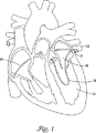
図1は、肺静脈12内に配置された寒冷療法器具10の透視図である。心房細動の1つのあり得る原因には、肺静脈12内の孤立病巣中枢内における異常な電気的活動が含まれ得ると考えられる。したがって、心房細動は、肺静脈12内の異常組織を切除することによって処置することができる。寒冷療法器具10は、肺静脈12またはそこに近接する組織の一部の寒冷誘導壊死および/または切除に使用され、心房細動のための有効な処置となっている。
FIG. 1 is a perspective view of a
肺静脈切除を実施するとき、寒冷療法器具10を患者の血管系を通し左心室14を通して左心房16に入れ、肺静脈12すぐ近くに操作することができる。あるいは、寒冷療法器具10を、図1に示されT−Sで示される経中隔アプローチ(trans−septal approach)で肺静脈12まで操作してもよい。寒冷療法器具10は、それと肺静脈12との間の表面接触を増大させるように環状構造に形成されることができる。環状構造の使用および表面接触の増大によって、臨床家が肺静脈12の所望の部分を切除することが可能になる。したがって、寒冷療法器具10は、肺静脈12の寒冷誘導壊死および/または切除を引き起こすように使用することができる。寒冷療法器具10は、たとえば引き紐17を動かすことによって環状構造内に操作することができる。引き紐17は、以下に説明し図7〜9に示されているように、寒冷療法器具10の外側に配置されるまたはその内部に配設されることができる。
When performing pulmonary vein resection, the
肺静脈12の一部を切除することによる心房細動の処置における潜在的な有用性に加えて、寒冷療法器具10をいくつかの他の医学的症状の処置に使用することもできる。たとえば、寒冷療法および/または寒冷形成術は、弁不全の静脈瘤の処置、心臓弁膜症、不整脈、僧帽弁閉鎖不全症治療、胃逆流症(gastric reflux disease)、胃食道逆流症、GURD、食道疾患、再狭窄、胃癌または子宮癌を含む癌の処置などに有効である。
In addition to its potential utility in the treatment of atrial fibrillation by excising a portion of the
図2は、寒冷療法器具10の断面図である。寒冷療法器具10は、内側管状シース18、管状シース18に隣接して配設されている冷却管20、冷却管20の少なくとも一部上に配設されている外管22、および冷却管20の少なくとも一部上に配設されている冷却部材24を含むことができる。さらに、冷却管20は、管状シース18まわりに配設されているコイル28を含む遠位領域26を含むことができる。
FIG. 2 is a cross-sectional view of the
管状シース18は、近位端30、遠位端32およびそれを通り抜けて延びる管腔34を有する、金属製(たとえばステンレス鋼製、ニッケルチタン合金製)ハイポチューブを備えることができる。(芯部材と呼んでも適当である)管状シース18は、芯線36上に摺動可能に配設されるように構成され適合されることができる。この実施形態によれば、管状シース18は、芯線36に対して所定の位置に移動されることができる。これは、芯線36を静止させておきながら、寒冷誘導壊死および/または切除の部位を変えるのに有用である。芯線36は、ガイドワイヤ、管または他の適当な構造を備えることができる。
Tubular sheath 18 may comprise a metal (eg, stainless steel, nickel titanium alloy) hypotube having a
コイル28は、管状シース18まわりに摺動可能に配設されることができる。いくつかの実施形態において、コイル28は、シース18のほぼ全長に沿って摺動可能に配設される。別の実施形態において、コイル28は、シース18の長さの一部(たとえば、冷却部材24の全長または長さの一部)に沿って摺動可能である。冷却管20は、遠位コイル28に加えて、管状シース18の長手方向軸とほぼ一直線にありそれをたどる近位領域38を含むこともできる。近位領域38は、たとえばルアー嵌合によってマニホールドに結合され得る近位端(図示せず)で終端することができる。マニホールドは、冷却剤源を備え、適量の冷却剤を冷却管20に送達することができる。
The
コイル28の一部は、放射線不透過性材料からなってよい。放射線不透過性材料は、医療処置の間、透視用蛍光板または他の画像化技術によって比較的明るい画像を生成することができると考えられる。この比較的明るい画像は、寒冷療法器具10の使用者がその位置を決定する助けとなる。放射線不透過性材料は、これらに限定されないが、金、白金、タングステン合金および放射線不透過性フィラーを装填したプラスチック材料を含むことができる。コイル28は、たとえば、少なくとも部分的に金めっきされてあってよい。さらに、寒冷療法器具10は、追加の放射線不透過性マーカーをさらに備えることができる。
A portion of the
外管22は、近位領域38付近において冷却管20の少なくとも一部を覆って配設されることができる。外管22は、金属製、高分子の重合体製またはその複合材料製であってよい。たとえば、外管22は、ポリイミドを含むことができる。外管22は、紐などの支持部材をさらに備えることができる。当業者は、外管22の適当な材料およびその製造に適当な構造に精通しているであろう。
The
冷却部材24は、遠位領域26付近において冷却管20の少なくとも一部上に配設されることができる。冷却部材は、外管22に結合されることができる。あるいは、外管22は、遠位軸40に結合されることもできる。この実施形態によれば、遠位軸40は、外管22に結合されることができる。別の実施形態において、冷却部材24は様々な長さを有することができる。たとえば、冷却部材24は、本質的に、管状シース18の長さ(たとえば約100〜300cmまたはそれ以上)にわたってよい。あるいは、冷却部材24の長さは、管状シース18の長さの一部にわたってもよく、または典型的な血管形成術用バルーンと寸法が同程度であってもよい。
The
冷却部材24は、LEAP IIバルーンを備えることができる。LEAP IIバルーンは、ポリエーテルブロックアミド(PEBA)からなる。ポリエーテルブロックアミドは、Atochem Polymers社(Birdsboro、Pennsylvania)からPEBAXの商品名で市販されている。あるいは、冷却部材24は、熱収縮高分子外層を有するステンレス鋼製またはニッケルチタン合金製の紐を備えることもできる。冷却部材24がどんな材料から構成されるかにかかわらず、冷却部材は、コイル28によって冷却部材24の内側表面42上に冷却剤が噴霧されて使用されることができる。したがって、冷却部材24は、対象域において寒冷誘導壊死を引き起こすか、または組織を切除することに使用できる。
The cooling
寒冷療法器具10は、近位端46、遠位端48およびそれを通り抜けて延びる管腔50を有する管44をさらに備えることができる。管腔50は、その中の温度が所定の温度より下がった場合、冷却剤を冷却部材24から排出することに使用される管腔である。この実施形態によれば、管44は、冷却部材24すぐ近くの温度を定量化することに使用され得る温度センサ52をさらに備える。
The
図2Aは、別の実施例の寒冷療法器具410の断面図である。寒冷療法器具410は、外側冷却部材425および第2の外管423を含み、第2の外管423と外管22との間に環状管腔476を画定すること以外、器具10と形および機能は本質的に同じである。外側冷却部材425は、器具にいくつか望ましい特徴をもたらすことができる。たとえば、外側冷却部材425によって、器具10の強さが増大され、その安全性が向上され、その冷却能力を変えるかまたは増大することなどができる。
FIG. 2A is a cross-sectional view of another
いくつかの実施形態において、環状管腔476は、真空下で維持されることができる。たとえば、第2の外管423の近位端は、真空装置またはマニホールドに結合されることができる。第2の外管423の長さに沿って真空を維持することによって、管423が断熱されてそれに沿った熱交換が最低限に抑えられることができる。さらに、ある物体が管腔476内(または外側冷却部材425と冷却部材24との間に位置された空間内)に配置され臨床家が排出を望む場合、その物体は吸引によって取り除かれることができる。
In some embodiments, the
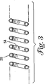
図3は、コイル28の断面図である。コイル28は、少なくとも1つの開口54を含むことができる。冷却管20を貫通する冷却剤は、開口54を通り冷却部材24の内側表面上42に噴霧されることができる。コイル28の多様な実施形態は、異なる構造および異なる数の開口を含むことができる。開口の数およびその構造における変更は、本発明の精神から逸脱することなく行うことができる。たとえば、コイル28は、冷却剤が内側表面42上に円環のように噴霧され得るようにほぼ円形構成で構成されている2、4、6または8つの開口を含むことができる。開口54の間隔は、規則的(すなわち、6つの開口54の間の離隔は60°、8つの開口54の間の離隔は45°など)であってよく、または不規則であってよい。
FIG. 3 is a cross-sectional view of the
開口54の形状は、冷却剤が内側表面42上に均一に噴射され得るように構成されることができる。たとえば、開口54は、均一な冷却剤噴射のために、切頭円錐(frusto−conical)の形を有するように構成されることができる。あるいは、均一な冷却剤噴射をもたらすために、開口54が、その中に配設されるフローダイレクティングノズル(flow directing nozzole)を有するか、またはフローダイレクティングノズルの形を有するように構成されることもできる。
The shape of the
使用において、寒冷療法器具10を病変または対象域にわたって従来のやり方で前進させることができる。次いで、冷却剤が冷却管20の開口54を通って放出されることができる。冷却によって、対象域の組織の温度が約0〜−81℃まで低下され、約2分間または約1〜5分間ずっとそれが行われる。
In use, the
使用される冷却剤は、エタノール混合物などの低凝固点液体、またはN2OもしくはCO2などの液化ガスを含むことができる。液体N2は、一般用の冷却剤として使用することができ、特に病変内の細胞の冷凍が望まれるとき有用である。フレオン、N2OガスおよびCO2ガスも冷却剤として使用することができる。他の冷却剤には、冷たい塩水、フルイゾル(Fluisol)、または塩水およびエタノールの混合物などを使用することができる。塩水などの冷却剤は、病変内の細胞の急激な冷凍が処置の目的でないとき使用され得ると予想される。他の冷却剤が、処置の目的1つまたは複数を達成するように同様のやり方で使用され得ることが当業者には明らかであろう。 The coolant used can include a low freezing point liquid such as an ethanol mixture, or a liquefied gas such as N 2 O or CO 2 . Liquid N 2 can be used as a general cooling agent and is particularly useful when freezing of cells within a lesion is desired. Freon, N 2 O gas and CO 2 gas can also be used as coolants. Other coolants can include cold brine, Fluisol, or a mixture of brine and ethanol. It is anticipated that coolants such as saline may be used when rapid freezing of cells within the lesion is not the purpose of the treatment. It will be apparent to those skilled in the art that other coolants can be used in a similar manner to achieve one or more of the treatment objectives.
説明のために、冷却剤がいかにして使用されるかという一実施例を以下に述べる。液体N2Oは、開口54から冷却部材の内側表面42上に噴霧されることができる。冷却剤の凝固(すなわち、液体CO2が使用される場合、ドライアイスの形成)を防止するために、冷却剤がたどる経路に沿って調整済み背圧が維持されることができる。次いで、寒冷療法器具10が、対象域たとえば肺静脈の冷却(すなわち冷凍、寒冷誘導損傷の引き起こし、切除など)に使用されることができる。処置の間、対象域に生成される開口部の寸法および深さは、心臓内超音波を含むいくつかの画像化技術によって切除前後に測定されることができる。
For purposes of illustration, an example of how coolant is used is described below. Liquid N 2 O can be sprayed from the
冷却は、ジュール−トムソン効果および蒸発潜熱両方の結果である。ジュール−トムソン効果は、高圧縮非理想気体が低圧力の領域内で膨張するときに起きる冷却効果として定義される。蒸発潜熱は、液体から気体への相変化の結果として放出される熱として定義される。凍結剤によっては、蒸発潜熱によって寒冷療法器具10での冷却の大部分がもたらされる。
Cooling is the result of both the Joule-Thomson effect and latent heat of vaporization. The Joule-Thomson effect is defined as the cooling effect that occurs when a highly compressed non-ideal gas expands in a region of low pressure. The latent heat of vaporization is defined as the heat released as a result of the phase change from liquid to gas. For some cryogens, latent heat of evaporation provides the majority of cooling in the
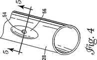
コイル28内の開口54は、いくつかの異なるやり方で製造されることができる。図4、5には、コイル28の製造方法の一実施例が示されている。図4はコイル28の斜視図である。この実施形態によれば、コイル28は、コイル28に形成されたへこみ56を含むことができる。へこみ56によって、開口54の形成を容易にすることができる。へこみ56は、厚さが減少しているコイル28の一部を画定することができる。たとえば、コイル28は直径約0.203mm(0.008インチ)であってよく、コイル28に近接する直径は約0.102mm(0.004インチ)であってよい。上記の設計によって、広い領域に凍結剤を配給するための均一な噴霧領域が作り出される。本発明の範囲を変更することなく、他の寸法および大きさが使用されることができる。
The
図5は、線5−5に沿ったコイル28の側面図である。開口54は、いくつかの異なる方法によってコイル28のへこみ56のところに形成されることができる。たとえば、コバルト製貫入ビット(puncture bit)は、コイル28内に穴を穿設し、したがって開口54を画定することに使用できる。開口54は、約0.051mm(0.002インチ)の直径または断面積D、または約0.254mm(0.010インチ)未満の直径であってよい。
FIG. 5 is a side view of
図6は、他の寒冷療法器具110の断面図である。寒冷療法器具110は、寒冷療法器具10について上記で述べた特徴の多くを有し、芯部材136上に摺動可能に配設されている冷却管120を含むことができる。芯部材136は、遠位端158を含むことができる。遠位端158は、それに結合されている全体的に先細りされた遠位先端160を有する。芯部材136は、ステンレス鋼製またはニッケルチタン合金製の芯線を備えるか、あるいは芯線を覆うようになされている(管状シース18と同様の)管状シースを備えることができる。後者の実施形態によれば、遠位先端160は、ガイドワイヤが貫通することができる溝をさらに備えることができる。
FIG. 6 is a cross-sectional view of another cryotherapy device 110. The cryotherapy device 110 has many of the features described above for the
図では、芯部材136に対して同軸的に構成されているコイル128が示されているが、コイル128は、芯部材136と平行に構成されることもでき、そうでなく冷却部材124内に配設されることもできる。器具110の他の実施形態は、芯部材136を含まない。それらの実施形態によれば、コイル128は冷却部材124内に摺動可能に配設されると述べることができる。
Although the figure shows a
冷却部材124は、支持部材164上に配設されている高分子熱収縮外管162を備えることができる。支持部材164は、ステンレス鋼製またはニッケルチタン合金製の紐を備えることができる。上記で述べたものと同様に、冷却部材が組織の寒冷誘導壊死および/または切除に使用され得るように冷却剤が冷却部材124の内側表面142上に噴霧されることができる。遠位先端160は、芯部材136に結合されることに加え、たとえばはんだ付けによって支持部材164に結合されることもできる。外管120は、冷却部材124に結合されることができる。
The cooling
上記で述べたものと同様に、冷却管120は、芯部材136の遠位端158に近接して配設されているコイル128を含むことができる。コイル128は、冷却部材124の内側表面124上に冷却剤を噴霧するようになされた少なくとも1つの開口154を含むことができる。コイル128は、芯部材136の長さに沿って摺動可能であってよい。この特徴によって、冷却部材124の長さに沿ったいくつかの場所において熱交換が行われるようになる。
Similar to that described above, the cooling
寒冷療法器具110は、上記で述べたものと同様であってよい管144を含むこともできる。あるいは、管144は、冷却管120に直接的に結合されることもできる。この実施形態によれば、管144は、芯部材136に対して摺動可能である。より具体的には、管144は、冷却管120に結合され、それによって芯部材136に対する冷却管120の動きが結果的に管144の動きとほぼ同様になされるようになる。
The cryotherapy device 110 may also include a
医療処置を実施するとき、(本明細書に記載されているものを含む)寒冷療法器具の位置を正確に制御することが望ましい。図7は、引き紐266を有する寒冷療法器具210装置の断面図である。引き紐266の使用は、本明細書に記載されているものを含む寒冷療法器具の他の実施形態に適用可能であることに留意されたい。引き紐266は、臨床家が直接的または間接的にアクセス可能である近位端および遠位端268を有することができる。遠位端268は、寒冷療法器具210の長さに沿ったいくつかの位置の任意の1つに結合されることができる。たとえば、引き紐266の遠位端268は、コイル228に結合されることができる。あるいは、遠位端268は、芯部材256に結合されることもできる。
When performing a medical procedure, it is desirable to accurately control the position of the cryotherapy device (including those described herein). FIG. 7 is a cross-sectional view of a
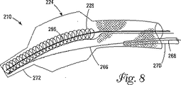
図8は、寒冷療法器具210の位置を変えるために引き紐266が動作されている、寒冷療法器具210の断面図である。図8には、器具210内に配設されている引き紐266の少なくとも一部が貫通するための任意選択のシース270も示されている。引き紐266を動かすことによって、寒冷療法器具210は屈曲されるか、またはそうでなくいくつかの異なる形および形態に変えられることができる。当業者は、本発明の多様な実施形態に適した様々な構造に精通しているであろう。
FIG. 8 is a cross-sectional view of the
図8では、コイル228は芯部材256に沿って摺動可能であり(または、より全体的には冷却室224内を摺動可能であり)、冷却室224の遠位端の方に摺動されることができることがわかる。いくつかの実施形態において、コイル228は、冷却室224の遠位端に配設されているネック付き遠位領域272まで進められることができる。これは、引き紐266を動かすとき、器具210の偏向の助けとなる。より具体的には、コイル228をネック付き遠位領域272に隣接する位置まで進めることによって、臨床家が、適宜器具210の遠位端を偏向することが可能になる。
In FIG. 8, the
図8に示されているものの代替として、引き紐266の一部は、寒冷療法器具210の遠位端の外側に配置されるか、または外に延ばされてよい。たとえば、図9には、引き紐366が器具310の遠位端から外に延びている環状形態の寒冷療法器具310が示されている。器具310は、本質的に、本明細書に記載されている他の寒冷療法器具と形状および機能は同じであり、その少なくとも一部に配設されているカテーテルシース374を含むことができる。(コイル328に直接的に連結されるまたは連結されなくてよい)引き紐366は、器具310の遠位端から外に延び、シース374の中へもどり、臨床家がそこにアクセス可能である近位方向にもどるように延びることができる。この構造によって、器具310の環状構造を制御し操作する臨床家の能力が向上される。いくつかの実施形態において、引き紐366は、細長い軸またはガイドワイヤ336を備えることができる。他の実施形態において、器具310は、図7、8の引き紐266と本質的に同じやり方で使用することができる(参照番号366’で示されている)第2の引き紐を含むこともできる。
As an alternative to what is shown in FIG. 8, a portion of the
本開示は、多くの点において、単なる説明のためのものであると理解されたい。本発明の範囲を逸脱することなく、詳細における、特に形状、寸法およびステップの構成の点において変更を加えることができる。当然、本発明の範囲は、添付の特許請求の範囲を表す言葉によって定義される。 It should be understood that the present disclosure is in many respects merely illustrative. Changes may be made in details, particularly in terms of shape, size and step configuration, without departing from the scope of the invention. Of course, the scope of the present invention is defined by the language used to describe the appended claims.
Claims (27)
猿位端の近くに配置された膨張可能部材を有する細長い部材であって、前記膨張可能部材は、寒冷治療が行われる組織に隣接して配置可能な外側表面を有し、前記細長い部材は管腔を有し、前記管腔は、前記膨張可能部材の内側空間の中で遠位方向に延びる、細長い部材と、
長手方向に延びる管腔を有する送達構造であって、前記管腔を通って、冷却剤は、前記空間の中へ前記送達構造の内の少なくとも1つの出口開口を通って遠位方向に流れ、前記送達構造はコイル部分を有し、前記コイル部分は少なくとも1つの出口開口を含み、前記コイル部分は前記空間内で長手方向に摺動可能であり、そして寒冷療法中に前記空間の内表面に対して前記少なくとも1つの出口開口の再配置を制御可能である、送達構造とを備える、医療装置。In medical devices that perform cryotherapy on tissues in the body's tubes,
An elongate member having an inflatable member disposed near the monkey end, the inflatable member having an outer surface positionable adjacent to a tissue to be subjected to cryotherapy, wherein the elongate member is a tube An elongate member having a lumen, the lumen extending distally within an interior space of the inflatable member;
A delivery structure having a longitudinally extending lumen, through which the coolant flows distally into the space through at least one outlet opening in the delivery structure; The delivery structure includes a coil portion, the coil portion includes at least one outlet opening , the coil portion is slidable longitudinally within the space, and is disposed on an inner surface of the space during cryotherapy. And a delivery structure that is controllable to reposition the at least one outlet opening.
芯線と、
管状シースを備える細長い芯部材であって、前記管状シースは、前記芯線のまわりで摺動可能に配設されるように適合される、細長い芯部材と、
前記芯部材に隣接して配設される寒冷管であって、前記寒冷管は、近位領域および遠位領域を有する、寒冷管とを備えており、前記遠位領域は、前記芯部材の少なくとも一部のまわりに摺動可能に配設されるコイルであって、前記コイルが、少なくとも1つの開口を含む、コイルと、前記寒冷管の少なくとも一部を覆って配設される外管と、前記コイルを覆って配設され且つ前記外管に結合される冷却部材と含む、寒冷療法器具。In cryotherapy equipment,
Core wire,
An elongated core member comprises a tubular sheath, the tubular-shaped sheath, said is adapted to be slidably disposed around the core, the elongate core member,
A chill tube disposed adjacent to the core member, the chill tube comprising a chill tube having a proximal region and a distal region, the distal region of the core member A coil slidably disposed about at least a portion, the coil including at least one opening, and an outer tube disposed over at least a portion of the cold tube. And a cooling member disposed over the coil and coupled to the outer tube.
Applications Claiming Priority (2)
| Application Number | Priority Date | Filing Date | Title |
|---|---|---|---|
| US10/231,738 US6929639B2 (en) | 2002-08-30 | 2002-08-30 | Cryo ablation coil |
| PCT/US2003/024129 WO2004019798A1 (en) | 2002-08-30 | 2003-07-31 | Cryo ablation coil |
Publications (3)
| Publication Number | Publication Date |
|---|---|
| JP2005537089A JP2005537089A (en) | 2005-12-08 |
| JP2005537089A5 JP2005537089A5 (en) | 2008-11-06 |
| JP4416654B2 true JP4416654B2 (en) | 2010-02-17 |
Family
ID=31976800
Family Applications (1)
| Application Number | Title | Priority Date | Filing Date |
|---|---|---|---|
| JP2004532847A Expired - Fee Related JP4416654B2 (en) | 2002-08-30 | 2003-07-31 | Cold resection coil |
Country Status (7)
| Country | Link |
|---|---|
| US (2) | US6929639B2 (en) |
| EP (1) | EP1531747B1 (en) |
| JP (1) | JP4416654B2 (en) |
| AT (1) | ATE540632T1 (en) |
| AU (1) | AU2003268047A1 (en) |
| CA (1) | CA2496575C (en) |
| WO (1) | WO2004019798A1 (en) |
Families Citing this family (145)
| Publication number | Priority date | Publication date | Assignee | Title |
|---|---|---|---|---|
| US7363071B2 (en) | 1999-05-26 | 2008-04-22 | Endocare, Inc. | Computer guided ablation of tissue using integrated ablative/temperature sensing devices |
| WO2003070547A1 (en) * | 2002-02-22 | 2003-08-28 | Bombardier Inc. | A three-wheeled vehicle having a split radiator and an interior storage compartment |
| US7756583B2 (en) | 2002-04-08 | 2010-07-13 | Ardian, Inc. | Methods and apparatus for intravascularly-induced neuromodulation |
| US8347891B2 (en) | 2002-04-08 | 2013-01-08 | Medtronic Ardian Luxembourg S.A.R.L. | Methods and apparatus for performing a non-continuous circumferential treatment of a body lumen |
| AU2004285412A1 (en) | 2003-09-12 | 2005-05-12 | Minnow Medical, Llc | Selectable eccentric remodeling and/or ablation of atherosclerotic material |
| NZ548679A (en) | 2003-12-22 | 2009-11-27 | Ams Res Corp | Cryosurgical devices and methods for endometrial ablation |
| US7288088B2 (en) | 2004-05-10 | 2007-10-30 | Boston Scientific Scimed, Inc. | Clamp based low temperature lesion formation apparatus, systems and methods |
| US7582083B2 (en) | 2004-05-10 | 2009-09-01 | Boston Scientific Scimed, Inc. | Probe based low temperature lesion formation apparatus, systems and methods |
| US7291142B2 (en) * | 2004-05-10 | 2007-11-06 | Boston Scientific Scimed, Inc. | Low temperature lesion formation apparatus, systems and methods |
| US9713730B2 (en) | 2004-09-10 | 2017-07-25 | Boston Scientific Scimed, Inc. | Apparatus and method for treatment of in-stent restenosis |
| US9277955B2 (en) | 2010-04-09 | 2016-03-08 | Vessix Vascular, Inc. | Power generating and control apparatus for the treatment of tissue |
| US8396548B2 (en) | 2008-11-14 | 2013-03-12 | Vessix Vascular, Inc. | Selective drug delivery in a lumen |
| US20060069385A1 (en) * | 2004-09-28 | 2006-03-30 | Scimed Life Systems, Inc. | Methods and apparatus for tissue cryotherapy |
| US7794455B2 (en) | 2005-04-29 | 2010-09-14 | Medtronic Cryocath Lp | Wide area ablation of myocardial tissue |
| US7740627B2 (en) | 2005-04-29 | 2010-06-22 | Medtronic Cryocath Lp | Surgical method and apparatus for treating atrial fibrillation |
| US8992515B2 (en) * | 2005-05-13 | 2015-03-31 | Medtronic Cryocath Lp | Coolant injection tube |
| US20060270981A1 (en) * | 2005-05-13 | 2006-11-30 | Leonilda Capuano | Coiled injection tube |
| US8019435B2 (en) | 2006-05-02 | 2011-09-13 | Boston Scientific Scimed, Inc. | Control of arterial smooth muscle tone |
| EP2540246B8 (en) | 2006-05-12 | 2020-10-07 | Vytronus, Inc. | Device for ablating body tissue |
| US9211393B2 (en) * | 2006-06-05 | 2015-12-15 | Medtronic Cryocath Lp | Distal cooling distribution system for a medical device |
| EP2455034B1 (en) | 2006-10-18 | 2017-07-19 | Vessix Vascular, Inc. | System for inducing desirable temperature effects on body tissue |
| CA2666661C (en) | 2006-10-18 | 2015-01-20 | Minnow Medical, Inc. | Tuned rf energy and electrical tissue characterization for selective treatment of target tissues |
| JP5479901B2 (en) | 2006-10-18 | 2014-04-23 | べシックス・バスキュラー・インコーポレイテッド | Induction of desired temperature effects on body tissue |
| US20080161890A1 (en) * | 2007-01-03 | 2008-07-03 | Boston Scientific Scimed, Inc. | Methods, systems, and apparatuses for protecting esophageal tissue during ablation |
| EP2022397A1 (en) * | 2007-08-08 | 2009-02-11 | ProRhythm, Inc. | Miniature circular mapping catheter |
| US8083733B2 (en) * | 2008-04-16 | 2011-12-27 | Icecure Medical Ltd. | Cryosurgical instrument with enhanced heat exchange |
| US9155588B2 (en) | 2008-06-13 | 2015-10-13 | Vytronus, Inc. | System and method for positioning an elongate member with respect to an anatomical structure |
| US20090312673A1 (en) * | 2008-06-14 | 2009-12-17 | Vytronus, Inc. | System and method for delivering energy to tissue |
| US20110178514A1 (en) * | 2008-06-18 | 2011-07-21 | Alexander Levin | Cryosurgical Instrument Insulating System |
| US8945106B2 (en) * | 2008-07-03 | 2015-02-03 | Steve Arless | Tip design for cryogenic probe with inner coil injection tube |
| US10363057B2 (en) | 2008-07-18 | 2019-07-30 | Vytronus, Inc. | System and method for delivering energy to tissue |
| EP2147662A1 (en) * | 2008-07-23 | 2010-01-27 | Abbott Laboratories Vascular Enterprises Limited | Stent delivery system |
| US8333757B2 (en) * | 2008-09-22 | 2012-12-18 | Boston Scientific Scimed, Inc. | Biasing a catheter balloon |
| US20100076634A1 (en) * | 2008-09-22 | 2010-03-25 | Ford Global Technologies, Llc | Method for Controlling a Micro-Hybrid Electric Vehicle with an Automatic Transmission |
| US10695126B2 (en) | 2008-10-06 | 2020-06-30 | Santa Anna Tech Llc | Catheter with a double balloon structure to generate and apply a heated ablative zone to tissue |
| US8465481B2 (en) * | 2008-10-20 | 2013-06-18 | Boston Scientific Scimed, Inc. | Providing cryotherapy with a balloon catheter having a non-uniform thermal profile |
| US8414508B2 (en) * | 2008-10-30 | 2013-04-09 | Vytronus, Inc. | System and method for delivery of energy to tissue while compensating for collateral tissue |
| US11298568B2 (en) | 2008-10-30 | 2022-04-12 | Auris Health, Inc. | System and method for energy delivery to tissue while monitoring position, lesion depth, and wall motion |
| US9220924B2 (en) | 2008-10-30 | 2015-12-29 | Vytronus, Inc. | System and method for energy delivery to tissue while monitoring position, lesion depth, and wall motion |
| US9033885B2 (en) * | 2008-10-30 | 2015-05-19 | Vytronus, Inc. | System and method for energy delivery to tissue while monitoring position, lesion depth, and wall motion |
| US9192789B2 (en) | 2008-10-30 | 2015-11-24 | Vytronus, Inc. | System and method for anatomical mapping of tissue and planning ablation paths therein |
| CN102271603A (en) | 2008-11-17 | 2011-12-07 | 明诺医学股份有限公司 | Selective accumulation of energy with or without knowledge of tissue topography |
| ES2447291T3 (en) | 2008-11-17 | 2014-03-11 | Vytronus, Inc. | System for ablation of body tissue |
| US8475379B2 (en) * | 2008-11-17 | 2013-07-02 | Vytronus, Inc. | Systems and methods for ablating body tissue |
| US8382746B2 (en) | 2008-11-21 | 2013-02-26 | C2 Therapeutics, Inc. | Cryogenic ablation system and method |
| WO2010070766A1 (en) * | 2008-12-19 | 2010-06-24 | 有限会社日本エレクテル | Balloon catheter system |
| WO2010081062A1 (en) * | 2009-01-12 | 2010-07-15 | Boston Scientific Scimed, Inc. | Systems and methods of making and using a coiled coolant transfer tube for a catheter of a cryoablation system |
| US20110257563A1 (en) | 2009-10-26 | 2011-10-20 | Vytronus, Inc. | Methods and systems for ablating tissue |
| US20110270238A1 (en) | 2009-12-31 | 2011-11-03 | Raed Rizq | Compliant Cryoballoon Apparatus for Denervating Ostia of the Renal Arteries |
| US20110263921A1 (en) | 2009-12-31 | 2011-10-27 | Anthony Vrba | Patterned Denervation Therapy for Innervated Renal Vasculature |
| US8926602B2 (en) | 2010-01-28 | 2015-01-06 | Medtronic Cryocath Lp | Triple balloon catheter |
| US20120089211A1 (en) * | 2010-04-08 | 2012-04-12 | Myoscience, Inc. | Methods and apparatus for cryogenically treating multiple tissue sites with a single puncture |
| US9192790B2 (en) | 2010-04-14 | 2015-11-24 | Boston Scientific Scimed, Inc. | Focused ultrasonic renal denervation |
| US8473067B2 (en) | 2010-06-11 | 2013-06-25 | Boston Scientific Scimed, Inc. | Renal denervation and stimulation employing wireless vascular energy transfer arrangement |
| US9084609B2 (en) | 2010-07-30 | 2015-07-21 | Boston Scientific Scime, Inc. | Spiral balloon catheter for renal nerve ablation |
| US9408661B2 (en) | 2010-07-30 | 2016-08-09 | Patrick A. Haverkost | RF electrodes on multiple flexible wires for renal nerve ablation |
| US9358365B2 (en) | 2010-07-30 | 2016-06-07 | Boston Scientific Scimed, Inc. | Precision electrode movement control for renal nerve ablation |
| US9155589B2 (en) | 2010-07-30 | 2015-10-13 | Boston Scientific Scimed, Inc. | Sequential activation RF electrode set for renal nerve ablation |
| US20120029512A1 (en) | 2010-07-30 | 2012-02-02 | Willard Martin R | Balloon with surface electrodes and integral cooling for renal nerve ablation |
| US9463062B2 (en) | 2010-07-30 | 2016-10-11 | Boston Scientific Scimed, Inc. | Cooled conductive balloon RF catheter for renal nerve ablation |
| EP2600784B1 (en) | 2010-08-05 | 2021-12-29 | Medtronic Ireland Manufacturing Unlimited Company | Cryoablation apparatuses, systems, and methods for renal neuromodulation |
| US8974451B2 (en) | 2010-10-25 | 2015-03-10 | Boston Scientific Scimed, Inc. | Renal nerve ablation using conductive fluid jet and RF energy |
| US20120158104A1 (en) | 2010-10-26 | 2012-06-21 | Medtronic Ardian Luxembourg S.A.R.L. | Neuromodulation cryotherapeutic devices and associated systems and methods |
| US9220558B2 (en) | 2010-10-27 | 2015-12-29 | Boston Scientific Scimed, Inc. | RF renal denervation catheter with multiple independent electrodes |
| US9028485B2 (en) | 2010-11-15 | 2015-05-12 | Boston Scientific Scimed, Inc. | Self-expanding cooling electrode for renal nerve ablation |
| US9668811B2 (en) | 2010-11-16 | 2017-06-06 | Boston Scientific Scimed, Inc. | Minimally invasive access for renal nerve ablation |
| US9089350B2 (en) | 2010-11-16 | 2015-07-28 | Boston Scientific Scimed, Inc. | Renal denervation catheter with RF electrode and integral contrast dye injection arrangement |
| US9326751B2 (en) | 2010-11-17 | 2016-05-03 | Boston Scientific Scimed, Inc. | Catheter guidance of external energy for renal denervation |
| US9060761B2 (en) | 2010-11-18 | 2015-06-23 | Boston Scientific Scime, Inc. | Catheter-focused magnetic field induced renal nerve ablation |
| US9192435B2 (en) | 2010-11-22 | 2015-11-24 | Boston Scientific Scimed, Inc. | Renal denervation catheter with cooled RF electrode |
| US9023034B2 (en) | 2010-11-22 | 2015-05-05 | Boston Scientific Scimed, Inc. | Renal ablation electrode with force-activatable conduction apparatus |
| US20120157993A1 (en) | 2010-12-15 | 2012-06-21 | Jenson Mark L | Bipolar Off-Wall Electrode Device for Renal Nerve Ablation |
| US9220561B2 (en) | 2011-01-19 | 2015-12-29 | Boston Scientific Scimed, Inc. | Guide-compatible large-electrode catheter for renal nerve ablation with reduced arterial injury |
| US20120259269A1 (en) | 2011-04-08 | 2012-10-11 | Tyco Healthcare Group Lp | Iontophoresis drug delivery system and method for denervation of the renal sympathetic nerve and iontophoretic drug delivery |
| CN103930061B (en) | 2011-04-25 | 2016-09-14 | 美敦力阿迪安卢森堡有限责任公司 | Relevant low temperature sacculus for restricted conduit wall cryogenic ablation limits the device and method disposed |
| US20120283722A1 (en) * | 2011-05-02 | 2012-11-08 | Medtronic Ablation Frontiers Llc | Adiabatic cooling system for medical devices |
| CN103442657B (en) | 2011-05-11 | 2016-05-25 | 艾斯酷瑞医药有限公司 | For the coil exchanger of Cryobiopsy probe |
| AU2012283908B2 (en) | 2011-07-20 | 2017-02-16 | Boston Scientific Scimed, Inc. | Percutaneous devices and methods to visualize, target and ablate nerves |
| WO2013016203A1 (en) | 2011-07-22 | 2013-01-31 | Boston Scientific Scimed, Inc. | Nerve modulation system with a nerve modulation element positionable in a helical guide |
| US9387031B2 (en) | 2011-07-29 | 2016-07-12 | Medtronic Ablation Frontiers Llc | Mesh-overlayed ablation and mapping device |
| EP2765942B1 (en) | 2011-10-10 | 2016-02-24 | Boston Scientific Scimed, Inc. | Medical devices including ablation electrodes |
| US10085799B2 (en) | 2011-10-11 | 2018-10-02 | Boston Scientific Scimed, Inc. | Off-wall electrode device and methods for nerve modulation |
| US9420955B2 (en) | 2011-10-11 | 2016-08-23 | Boston Scientific Scimed, Inc. | Intravascular temperature monitoring system and method |
| US9364284B2 (en) | 2011-10-12 | 2016-06-14 | Boston Scientific Scimed, Inc. | Method of making an off-wall spacer cage |
| US9079000B2 (en) | 2011-10-18 | 2015-07-14 | Boston Scientific Scimed, Inc. | Integrated crossing balloon catheter |
| EP2768563B1 (en) | 2011-10-18 | 2016-11-09 | Boston Scientific Scimed, Inc. | Deflectable medical devices |
| EP2775948B1 (en) | 2011-11-08 | 2018-04-04 | Boston Scientific Scimed, Inc. | Ostial renal nerve ablation |
| EP2779929A1 (en) | 2011-11-15 | 2014-09-24 | Boston Scientific Scimed, Inc. | Device and methods for renal nerve modulation monitoring |
| US9119632B2 (en) | 2011-11-21 | 2015-09-01 | Boston Scientific Scimed, Inc. | Deflectable renal nerve ablation catheter |
| US9265969B2 (en) | 2011-12-21 | 2016-02-23 | Cardiac Pacemakers, Inc. | Methods for modulating cell function |
| WO2013096913A2 (en) | 2011-12-23 | 2013-06-27 | Vessix Vascular, Inc. | Methods and apparatuses for remodeling tissue of or adjacent to a body passage |
| JP2013132364A (en) * | 2011-12-26 | 2013-07-08 | Nippon Erekuteru:Kk | Balloon catheter |
| WO2013101452A1 (en) | 2011-12-28 | 2013-07-04 | Boston Scientific Scimed, Inc. | Device and methods for nerve modulation using a novel ablation catheter with polymeric ablative elements |
| US9050106B2 (en) | 2011-12-29 | 2015-06-09 | Boston Scientific Scimed, Inc. | Off-wall electrode device and methods for nerve modulation |
| US20150088113A1 (en) | 2012-04-27 | 2015-03-26 | Medtronic Ardian Luxembourg S.A.R.L. | Cryotherapeutic devices for renal neuromodulation and associated systems and methods |
| US9241752B2 (en) | 2012-04-27 | 2016-01-26 | Medtronic Ardian Luxembourg S.A.R.L. | Shafts with pressure relief in cryotherapeutic catheters and associated devices, systems, and methods |
| US10660703B2 (en) | 2012-05-08 | 2020-05-26 | Boston Scientific Scimed, Inc. | Renal nerve modulation devices |
| US10321946B2 (en) | 2012-08-24 | 2019-06-18 | Boston Scientific Scimed, Inc. | Renal nerve modulation devices with weeping RF ablation balloons |
| US9113911B2 (en) | 2012-09-06 | 2015-08-25 | Medtronic Ablation Frontiers Llc | Ablation device and method for electroporating tissue cells |
| EP2895095A2 (en) | 2012-09-17 | 2015-07-22 | Boston Scientific Scimed, Inc. | Self-positioning electrode system and method for renal nerve modulation |
| US10398464B2 (en) | 2012-09-21 | 2019-09-03 | Boston Scientific Scimed, Inc. | System for nerve modulation and innocuous thermal gradient nerve block |
| US10549127B2 (en) | 2012-09-21 | 2020-02-04 | Boston Scientific Scimed, Inc. | Self-cooling ultrasound ablation catheter |
| JP6074051B2 (en) | 2012-10-10 | 2017-02-01 | ボストン サイエンティフィック サイムド,インコーポレイテッドBoston Scientific Scimed,Inc. | Intravascular neuromodulation system and medical device |
| WO2014143571A1 (en) | 2013-03-11 | 2014-09-18 | Boston Scientific Scimed, Inc. | Medical devices for modulating nerves |
| US9956033B2 (en) | 2013-03-11 | 2018-05-01 | Boston Scientific Scimed, Inc. | Medical devices for modulating nerves |
| US9808311B2 (en) | 2013-03-13 | 2017-11-07 | Boston Scientific Scimed, Inc. | Deflectable medical devices |
| JP6220044B2 (en) | 2013-03-15 | 2017-10-25 | ボストン サイエンティフィック サイムド,インコーポレイテッドBoston Scientific Scimed,Inc. | Medical device for renal nerve ablation |
| US10105159B2 (en) * | 2013-03-15 | 2018-10-23 | W.L. Gore Associates, Inc | Recanalization device |
| US10265122B2 (en) | 2013-03-15 | 2019-04-23 | Boston Scientific Scimed, Inc. | Nerve ablation devices and related methods of use |
| CN105228546B (en) | 2013-03-15 | 2017-11-14 | 波士顿科学国际有限公司 | Utilize the impedance-compensated medicine equipment and method that are used to treat hypertension |
| US9943365B2 (en) | 2013-06-21 | 2018-04-17 | Boston Scientific Scimed, Inc. | Renal denervation balloon catheter with ride along electrode support |
| JP2016524949A (en) | 2013-06-21 | 2016-08-22 | ボストン サイエンティフィック サイムド,インコーポレイテッドBoston Scientific Scimed,Inc. | Medical device for renal nerve ablation having a rotatable shaft |
| US9707036B2 (en) | 2013-06-25 | 2017-07-18 | Boston Scientific Scimed, Inc. | Devices and methods for nerve modulation using localized indifferent electrodes |
| WO2015002787A1 (en) | 2013-07-01 | 2015-01-08 | Boston Scientific Scimed, Inc. | Medical devices for renal nerve ablation |
| US10660698B2 (en) | 2013-07-11 | 2020-05-26 | Boston Scientific Scimed, Inc. | Devices and methods for nerve modulation |
| EP3019106A1 (en) | 2013-07-11 | 2016-05-18 | Boston Scientific Scimed, Inc. | Medical device with stretchable electrode assemblies |
| EP3049007B1 (en) | 2013-07-19 | 2019-06-12 | Boston Scientific Scimed, Inc. | Spiral bipolar electrode renal denervation balloon |
| US10695124B2 (en) | 2013-07-22 | 2020-06-30 | Boston Scientific Scimed, Inc. | Renal nerve ablation catheter having twist balloon |
| WO2015013205A1 (en) | 2013-07-22 | 2015-01-29 | Boston Scientific Scimed, Inc. | Medical devices for renal nerve ablation |
| JP6159888B2 (en) | 2013-08-22 | 2017-07-05 | ボストン サイエンティフィック サイムド,インコーポレイテッドBoston Scientific Scimed,Inc. | Flexible circuit with improved adhesion to renal neuromodulation balloon |
| US9895194B2 (en) | 2013-09-04 | 2018-02-20 | Boston Scientific Scimed, Inc. | Radio frequency (RF) balloon catheter having flushing and cooling capability |
| CN105530885B (en) | 2013-09-13 | 2020-09-22 | 波士顿科学国际有限公司 | Ablation balloon with vapor deposited covering |
| EP3049005B1 (en) | 2013-09-24 | 2022-08-10 | Adagio Medical, Inc. | Endovascular near critical fluid based cryoablation catheter |
| US11246654B2 (en) | 2013-10-14 | 2022-02-15 | Boston Scientific Scimed, Inc. | Flexible renal nerve ablation devices and related methods of use and manufacture |
| WO2015057521A1 (en) | 2013-10-14 | 2015-04-23 | Boston Scientific Scimed, Inc. | High resolution cardiac mapping electrode array catheter |
| EP3057520A1 (en) | 2013-10-15 | 2016-08-24 | Boston Scientific Scimed, Inc. | Medical device balloon |
| US9770606B2 (en) | 2013-10-15 | 2017-09-26 | Boston Scientific Scimed, Inc. | Ultrasound ablation catheter with cooling infusion and centering basket |
| JP6259099B2 (en) | 2013-10-18 | 2018-01-10 | ボストン サイエンティフィック サイムド,インコーポレイテッドBoston Scientific Scimed,Inc. | Balloon catheter comprising a conductive wire with flexibility, and related uses and manufacturing methods |
| CN105658163B (en) | 2013-10-25 | 2020-08-18 | 波士顿科学国际有限公司 | Embedded thermocouple in denervation flexible circuit |
| WO2015103617A1 (en) | 2014-01-06 | 2015-07-09 | Boston Scientific Scimed, Inc. | Tear resistant flex circuit assembly |
| EP3102136B1 (en) | 2014-02-04 | 2018-06-27 | Boston Scientific Scimed, Inc. | Alternative placement of thermal sensors on bipolar electrode |
| US11000679B2 (en) | 2014-02-04 | 2021-05-11 | Boston Scientific Scimed, Inc. | Balloon protection and rewrapping devices and related methods of use |
| US10492842B2 (en) | 2014-03-07 | 2019-12-03 | Medtronic Ardian Luxembourg S.A.R.L. | Monitoring and controlling internally administered cryotherapy |
| US20150289750A1 (en) * | 2014-04-11 | 2015-10-15 | Jeremy Stigall | Imaging and treatment device |
| US10709490B2 (en) | 2014-05-07 | 2020-07-14 | Medtronic Ardian Luxembourg S.A.R.L. | Catheter assemblies comprising a direct heating element for renal neuromodulation and associated systems and methods |
| US9414878B1 (en) | 2015-05-15 | 2016-08-16 | C2 Therapeutics, Inc. | Cryogenic balloon ablation system |
| US10549128B2 (en) | 2015-11-04 | 2020-02-04 | Vytronus, Inc. | Systems and methods for imaging and ablating tissue |
| US11331140B2 (en) | 2016-05-19 | 2022-05-17 | Aqua Heart, Inc. | Heated vapor ablation systems and methods for treating cardiac conditions |
| US10251693B2 (en) | 2016-05-20 | 2019-04-09 | Pentax Of America, Inc. | Cryogenic ablation system with rotatable and translatable catheter |
| AU2018328115A1 (en) | 2017-09-05 | 2020-04-02 | Adagio Medical, Inc. | Ablation catheter having a shape memory stylet |
| WO2019071269A2 (en) | 2017-10-06 | 2019-04-11 | Powell Charles Lee | System and method to treat obstructive sleep apnea |
| US11419657B2 (en) | 2017-11-30 | 2022-08-23 | Boston Scientific Scimed, Inc. | Compensation assembly for fluid injection line of intravascular catheter system |
| CA3087772A1 (en) * | 2018-01-10 | 2019-07-18 | Adagio Medical, Inc. | Cryoablation element with conductive liner |
| AU2020328064B2 (en) * | 2019-08-14 | 2024-02-08 | Biocompatibles Uk Limited | Dual stage cryocooler |
| US11633224B2 (en) | 2020-02-10 | 2023-04-25 | Icecure Medical Ltd. | Cryogen pump |
Family Cites Families (16)
| Publication number | Priority date | Publication date | Assignee | Title |
|---|---|---|---|---|
| DE2831199C3 (en) * | 1978-07-15 | 1981-01-08 | Erbe Elektromedizin Gmbh & Co Kg, 7400 Tuebingen | Cryosurgical device |
| US5135531A (en) * | 1984-05-14 | 1992-08-04 | Surgical Systems & Instruments, Inc. | Guided atherectomy system |
| US5147355A (en) * | 1988-09-23 | 1992-09-15 | Brigham And Womens Hospital | Cryoablation catheter and method of performing cryoablation |
| US5624392A (en) * | 1990-05-11 | 1997-04-29 | Saab; Mark A. | Heat transfer catheters and methods of making and using same |
| US5281215A (en) * | 1992-04-16 | 1994-01-25 | Implemed, Inc. | Cryogenic catheter |
| US5334193A (en) * | 1992-11-13 | 1994-08-02 | American Cardiac Ablation Co., Inc. | Fluid cooled ablation catheter |
| NL9301851A (en) * | 1993-10-26 | 1995-05-16 | Cordis Europ | Cryo-ablation catheter. |
| GB2283678B (en) | 1993-11-09 | 1998-06-03 | Spembly Medical Ltd | Cryosurgical catheter probe |
| US5868735A (en) * | 1997-03-06 | 1999-02-09 | Scimed Life Systems, Inc. | Cryoplasty device and method |
| US7220257B1 (en) | 2000-07-25 | 2007-05-22 | Scimed Life Systems, Inc. | Cryotreatment device and method |
| US6024740A (en) * | 1997-07-08 | 2000-02-15 | The Regents Of The University Of California | Circumferential ablation device assembly |
| US5971979A (en) * | 1997-12-02 | 1999-10-26 | Odyssey Technologies, Inc. | Method for cryogenic inhibition of hyperplasia |
| US6685732B2 (en) * | 1998-03-31 | 2004-02-03 | Innercool Therapies, Inc. | Method and device for performing cooling- or cryo-therapies for, e.g., angioplasty with reduced restenosis or pulmonary vein cell necrosis to inhibit atrial fibrillation employing microporous balloon |
| US7291144B2 (en) * | 1998-03-31 | 2007-11-06 | Innercool Therapies, Inc. | Method and device for performing cooling- or cryo-therapies for, e.g., angioplasty with reduced restenosis or pulmonary vein cell necrosis to inhibit atrial fibrillation |
| WO1999065410A1 (en) * | 1998-06-19 | 1999-12-23 | Endocare, Inc. | Sheath, cryoprobe, and methods for use |
| US6551274B2 (en) * | 2000-02-29 | 2003-04-22 | Biosense Webster, Inc. | Cryoablation catheter with an expandable cooling chamber |
-
2002
- 2002-08-30 US US10/231,738 patent/US6929639B2/en not_active Expired - Lifetime
-
2003
- 2003-07-31 AU AU2003268047A patent/AU2003268047A1/en not_active Abandoned
- 2003-07-31 CA CA2496575A patent/CA2496575C/en not_active Expired - Fee Related
- 2003-07-31 EP EP03748998A patent/EP1531747B1/en not_active Expired - Lifetime
- 2003-07-31 JP JP2004532847A patent/JP4416654B2/en not_active Expired - Fee Related
- 2003-07-31 WO PCT/US2003/024129 patent/WO2004019798A1/en active Application Filing
- 2003-07-31 AT AT03748998T patent/ATE540632T1/en active
-
2005
- 2005-03-31 US US11/094,863 patent/US7172589B2/en not_active Expired - Lifetime
Also Published As
| Publication number | Publication date |
|---|---|
| EP1531747B1 (en) | 2012-01-11 |
| US20050182396A1 (en) | 2005-08-18 |
| US20040044334A1 (en) | 2004-03-04 |
| WO2004019798A1 (en) | 2004-03-11 |
| US6929639B2 (en) | 2005-08-16 |
| JP2005537089A (en) | 2005-12-08 |
| AU2003268047A1 (en) | 2004-03-19 |
| CA2496575C (en) | 2012-02-21 |
| EP1531747A1 (en) | 2005-05-25 |
| CA2496575A1 (en) | 2004-03-11 |
| ATE540632T1 (en) | 2012-01-15 |
| US7172589B2 (en) | 2007-02-06 |
Similar Documents
| Publication | Publication Date | Title |
|---|---|---|
| JP4416654B2 (en) | Cold resection coil | |
| US20230255673A1 (en) | Ablation catheter having a shape memory stylet | |
| US10070910B2 (en) | Apparatus and methods for cryogenically ablating tissue and adjusting cryogenic ablation regions | |
| US7625369B2 (en) | Method and device for epicardial ablation | |
| JP4833494B2 (en) | Cryotherapy apparatus and method | |
| US6666858B2 (en) | Cryo balloon for atrial ablation | |
| US20210315627A1 (en) | Ablation catheter having an expandable treatment portion | |
| EP1786345B1 (en) | Apparatus for creating a linear ablation | |
| US20110028962A1 (en) | Adjustable pulmonary vein ablation catheter | |
| JP2005052630A (en) | Freeze-thawing necrosis treating system and method | |
| US20230389977A1 (en) | Cryoablation element with conductive liner | |
| CN116209405A (en) | Novel shunt manifold for cryoablation catheter |
Legal Events
| Date | Code | Title | Description |
|---|---|---|---|
| A521 | Request for written amendment filed |
Free format text: JAPANESE INTERMEDIATE CODE: A523 Effective date: 20060725 |
|
| A621 | Written request for application examination |
Free format text: JAPANESE INTERMEDIATE CODE: A621 Effective date: 20060725 |
|
| A521 | Request for written amendment filed |
Free format text: JAPANESE INTERMEDIATE CODE: A523 Effective date: 20060913 |
|
| A521 | Request for written amendment filed |
Free format text: JAPANESE INTERMEDIATE CODE: A523 Effective date: 20080918 |
|
| A521 | Request for written amendment filed |
Free format text: JAPANESE INTERMEDIATE CODE: A821 Effective date: 20081212 |
|
| RD02 | Notification of acceptance of power of attorney |
Free format text: JAPANESE INTERMEDIATE CODE: A7422 Effective date: 20081212 |
|
| RD04 | Notification of resignation of power of attorney |
Free format text: JAPANESE INTERMEDIATE CODE: A7424 Effective date: 20090116 |
|
| A131 | Notification of reasons for refusal |
Free format text: JAPANESE INTERMEDIATE CODE: A131 Effective date: 20090521 |
|
| A601 | Written request for extension of time |
Free format text: JAPANESE INTERMEDIATE CODE: A601 Effective date: 20090820 |
|
| A602 | Written permission of extension of time |
Free format text: JAPANESE INTERMEDIATE CODE: A602 Effective date: 20090827 |
|
| A521 | Request for written amendment filed |
Free format text: JAPANESE INTERMEDIATE CODE: A523 Effective date: 20090917 |
|
| TRDD | Decision of grant or rejection written | ||
| A01 | Written decision to grant a patent or to grant a registration (utility model) |
Free format text: JAPANESE INTERMEDIATE CODE: A01 Effective date: 20091028 |
|
| A01 | Written decision to grant a patent or to grant a registration (utility model) |
Free format text: JAPANESE INTERMEDIATE CODE: A01 |
|
| A61 | First payment of annual fees (during grant procedure) |
Free format text: JAPANESE INTERMEDIATE CODE: A61 Effective date: 20091124 |
|
| R150 | Certificate of patent or registration of utility model |
Ref document number: 4416654 Country of ref document: JP Free format text: JAPANESE INTERMEDIATE CODE: R150 Free format text: JAPANESE INTERMEDIATE CODE: R150 |
|
| FPAY | Renewal fee payment (event date is renewal date of database) |
Free format text: PAYMENT UNTIL: 20121204 Year of fee payment: 3 |
|
| FPAY | Renewal fee payment (event date is renewal date of database) |
Free format text: PAYMENT UNTIL: 20121204 Year of fee payment: 3 |
|
| FPAY | Renewal fee payment (event date is renewal date of database) |
Free format text: PAYMENT UNTIL: 20131204 Year of fee payment: 4 |
|
| R250 | Receipt of annual fees |
Free format text: JAPANESE INTERMEDIATE CODE: R250 |
|
| R250 | Receipt of annual fees |
Free format text: JAPANESE INTERMEDIATE CODE: R250 |
|
| R250 | Receipt of annual fees |
Free format text: JAPANESE INTERMEDIATE CODE: R250 |
|
| R250 | Receipt of annual fees |
Free format text: JAPANESE INTERMEDIATE CODE: R250 |
|
| R250 | Receipt of annual fees |
Free format text: JAPANESE INTERMEDIATE CODE: R250 |
|
| R250 | Receipt of annual fees |
Free format text: JAPANESE INTERMEDIATE CODE: R250 |
|
| R250 | Receipt of annual fees |
Free format text: JAPANESE INTERMEDIATE CODE: R250 |
|
| R250 | Receipt of annual fees |
Free format text: JAPANESE INTERMEDIATE CODE: R250 |
|
| R250 | Receipt of annual fees |
Free format text: JAPANESE INTERMEDIATE CODE: R250 |
|
| R250 | Receipt of annual fees |
Free format text: JAPANESE INTERMEDIATE CODE: R250 |
|
| LAPS | Cancellation because of no payment of annual fees |