JP4414760B2 - Stent for delivery of therapeutic or other drugs - Google Patents
Stent for delivery of therapeutic or other drugs Download PDFInfo
- Publication number
- JP4414760B2 JP4414760B2 JP2003548729A JP2003548729A JP4414760B2 JP 4414760 B2 JP4414760 B2 JP 4414760B2 JP 2003548729 A JP2003548729 A JP 2003548729A JP 2003548729 A JP2003548729 A JP 2003548729A JP 4414760 B2 JP4414760 B2 JP 4414760B2
- Authority
- JP
- Japan
- Prior art keywords
- stent
- recess
- serpentine
- strut
- adjacent
- Prior art date
- Legal status (The legal status is an assumption and is not a legal conclusion. Google has not performed a legal analysis and makes no representation as to the accuracy of the status listed.)
- Expired - Fee Related
Links
- 239000003814 drug Substances 0.000 title claims description 70
- 229940079593 drug Drugs 0.000 title description 37
- 230000001225 therapeutic effect Effects 0.000 title description 2
- WYTGDNHDOZPMIW-RCBQFDQVSA-N alstonine Natural products C1=CC2=C3C=CC=CC3=NC2=C2N1C[C@H]1[C@H](C)OC=C(C(=O)OC)[C@H]1C2 WYTGDNHDOZPMIW-RCBQFDQVSA-N 0.000 claims description 98
- 229940124597 therapeutic agent Drugs 0.000 claims description 33
- 239000003146 anticoagulant agent Substances 0.000 claims description 14
- 239000000126 substance Substances 0.000 claims description 10
- 239000003102 growth factor Substances 0.000 claims description 9
- 239000004019 antithrombin Substances 0.000 claims description 8
- 230000000702 anti-platelet effect Effects 0.000 claims description 7
- 230000001028 anti-proliverative effect Effects 0.000 claims description 6
- 229940127219 anticoagulant drug Drugs 0.000 claims description 5
- 230000015572 biosynthetic process Effects 0.000 claims description 5
- 230000000118 anti-neoplastic effect Effects 0.000 claims description 4
- -1 antifibrin Substances 0.000 claims description 4
- 229940124599 anti-inflammatory drug Drugs 0.000 claims description 3
- 239000000043 antiallergic agent Substances 0.000 claims description 3
- 229940034982 antineoplastic agent Drugs 0.000 claims description 3
- 239000003242 anti bacterial agent Substances 0.000 claims description 2
- 230000002927 anti-mitotic effect Effects 0.000 claims description 2
- 229940088710 antibiotic agent Drugs 0.000 claims description 2
- 239000003080 antimitotic agent Substances 0.000 claims description 2
- 239000003963 antioxidant agent Substances 0.000 claims description 2
- 239000003795 chemical substances by application Substances 0.000 claims description 2
- 230000002068 genetic effect Effects 0.000 claims description 2
- 239000003112 inhibitor Substances 0.000 description 15
- WQPDUTSPKFMPDP-OUMQNGNKSA-N hirudin Chemical compound C([C@@H](C(=O)N[C@@H](CCC(O)=O)C(=O)N[C@@H](CCC(O)=O)C(=O)N[C@@H]([C@@H](C)CC)C(=O)N1[C@@H](CCC1)C(=O)N[C@@H](CCC(O)=O)C(=O)N[C@@H](CCC(O)=O)C(=O)N[C@@H](CC=1C=CC(OS(O)(=O)=O)=CC=1)C(=O)N[C@@H](CC(C)C)C(=O)N[C@@H](CCC(N)=O)C(O)=O)NC(=O)[C@H](CC(O)=O)NC(=O)CNC(=O)[C@H](CC(O)=O)NC(=O)[C@H](CC(N)=O)NC(=O)[C@H](CC=1NC=NC=1)NC(=O)[C@H](CO)NC(=O)[C@H](CCC(N)=O)NC(=O)[C@H]1N(CCC1)C(=O)[C@H](CCCCN)NC(=O)[C@H]1N(CCC1)C(=O)[C@@H](NC(=O)CNC(=O)[C@H](CCC(O)=O)NC(=O)CNC(=O)[C@@H](NC(=O)[C@@H](NC(=O)[C@H]1NC(=O)[C@H](CCC(N)=O)NC(=O)[C@H](CC(N)=O)NC(=O)[C@H](CCCCN)NC(=O)[C@H](CCC(O)=O)NC(=O)CNC(=O)[C@H](CC(O)=O)NC(=O)[C@H](CO)NC(=O)CNC(=O)[C@H](CC(C)C)NC(=O)[C@H]([C@@H](C)CC)NC(=O)[C@@H]2CSSC[C@@H](C(=O)N[C@@H](CCC(O)=O)C(=O)NCC(=O)N[C@@H](CO)C(=O)N[C@@H](CC(N)=O)C(=O)N[C@H](C(=O)N[C@H](C(NCC(=O)N[C@@H](CCC(N)=O)C(=O)NCC(=O)N[C@@H](CC(N)=O)C(=O)N[C@@H](CCCCN)C(=O)N2)=O)CSSC1)C(C)C)NC(=O)[C@H](CC(C)C)NC(=O)[C@H]1NC(=O)[C@H](CC(C)C)NC(=O)[C@H](CC(N)=O)NC(=O)[C@H](CCC(N)=O)NC(=O)CNC(=O)[C@H](CO)NC(=O)[C@H](CCC(O)=O)NC(=O)[C@H]([C@@H](C)O)NC(=O)[C@@H](NC(=O)[C@H](CC(O)=O)NC(=O)[C@@H](NC(=O)[C@H](CC=2C=CC(O)=CC=2)NC(=O)[C@@H](NC(=O)[C@@H](N)C(C)C)C(C)C)[C@@H](C)O)CSSC1)C(C)C)[C@@H](C)O)[C@@H](C)O)C1=CC=CC=C1 WQPDUTSPKFMPDP-OUMQNGNKSA-N 0.000 description 7
- 239000000463 material Substances 0.000 description 7
- 238000000034 method Methods 0.000 description 7
- 102000004169 proteins and genes Human genes 0.000 description 7
- 108090000623 proteins and genes Proteins 0.000 description 7
- HTTJABKRGRZYRN-UHFFFAOYSA-N Heparin Chemical compound OC1C(NC(=O)C)C(O)OC(COS(O)(=O)=O)C1OC1C(OS(O)(=O)=O)C(O)C(OC2C(C(OS(O)(=O)=O)C(OC3C(C(O)C(O)C(O3)C(O)=O)OS(O)(=O)=O)C(CO)O2)NS(O)(=O)=O)C(C(O)=O)O1 HTTJABKRGRZYRN-UHFFFAOYSA-N 0.000 description 5
- 210000001367 artery Anatomy 0.000 description 5
- 210000004204 blood vessel Anatomy 0.000 description 5
- 210000004027 cell Anatomy 0.000 description 5
- 239000011248 coating agent Substances 0.000 description 5
- 238000000576 coating method Methods 0.000 description 5
- 230000007423 decrease Effects 0.000 description 5
- 238000012377 drug delivery Methods 0.000 description 5
- 229920000669 heparin Polymers 0.000 description 5
- 108010007726 Bone Morphogenetic Proteins Proteins 0.000 description 4
- 102000007350 Bone Morphogenetic Proteins Human genes 0.000 description 4
- AOJJSUZBOXZQNB-TZSSRYMLSA-N Doxorubicin Chemical compound O([C@H]1C[C@@](O)(CC=2C(O)=C3C(=O)C=4C=CC=C(C=4C(=O)C3=C(O)C=21)OC)C(=O)CO)[C@H]1C[C@H](N)[C@H](O)[C@H](C)O1 AOJJSUZBOXZQNB-TZSSRYMLSA-N 0.000 description 4
- OHCQJHSOBUTRHG-KGGHGJDLSA-N FORSKOLIN Chemical compound O=C([C@@]12O)C[C@](C)(C=C)O[C@]1(C)[C@@H](OC(=O)C)[C@@H](O)[C@@H]1[C@]2(C)[C@@H](O)CCC1(C)C OHCQJHSOBUTRHG-KGGHGJDLSA-N 0.000 description 4
- 108010007267 Hirudins Proteins 0.000 description 4
- 102000007625 Hirudins Human genes 0.000 description 4
- 229940112869 bone morphogenetic protein Drugs 0.000 description 4
- 239000006227 byproduct Substances 0.000 description 4
- 229940006607 hirudin Drugs 0.000 description 4
- 230000002401 inhibitory effect Effects 0.000 description 4
- 230000001788 irregular Effects 0.000 description 4
- 108010049870 Bone Morphogenetic Protein 7 Proteins 0.000 description 3
- 102100022544 Bone morphogenetic protein 7 Human genes 0.000 description 3
- 239000002131 composite material Substances 0.000 description 3
- 229960001123 epoprostenol Drugs 0.000 description 3
- KAQKFAOMNZTLHT-VVUHWYTRSA-N epoprostenol Chemical compound O1C(=CCCCC(O)=O)C[C@@H]2[C@@H](/C=C/[C@@H](O)CCCCC)[C@H](O)C[C@@H]21 KAQKFAOMNZTLHT-VVUHWYTRSA-N 0.000 description 3
- 229960002897 heparin Drugs 0.000 description 3
- 239000004081 narcotic agent Substances 0.000 description 3
- 229910001000 nickel titanium Inorganic materials 0.000 description 3
- 108090000765 processed proteins & peptides Proteins 0.000 description 3
- 150000003815 prostacyclins Chemical class 0.000 description 3
- 239000002089 prostaglandin antagonist Substances 0.000 description 3
- 102000005962 receptors Human genes 0.000 description 3
- 108020003175 receptors Proteins 0.000 description 3
- KWPACVJPAFGBEQ-IKGGRYGDSA-N (2s)-1-[(2r)-2-amino-3-phenylpropanoyl]-n-[(3s)-1-chloro-6-(diaminomethylideneamino)-2-oxohexan-3-yl]pyrrolidine-2-carboxamide Chemical compound C([C@@H](N)C(=O)N1[C@@H](CCC1)C(=O)N[C@@H](CCCNC(N)=N)C(=O)CCl)C1=CC=CC=C1 KWPACVJPAFGBEQ-IKGGRYGDSA-N 0.000 description 2
- IAKHMKGGTNLKSZ-INIZCTEOSA-N (S)-colchicine Chemical compound C1([C@@H](NC(C)=O)CC2)=CC(=O)C(OC)=CC=C1C1=C2C=C(OC)C(OC)=C1OC IAKHMKGGTNLKSZ-INIZCTEOSA-N 0.000 description 2
- 206010002329 Aneurysm Diseases 0.000 description 2
- 108010049931 Bone Morphogenetic Protein 2 Proteins 0.000 description 2
- 108010049951 Bone Morphogenetic Protein 3 Proteins 0.000 description 2
- 108010049955 Bone Morphogenetic Protein 4 Proteins 0.000 description 2
- 108010049976 Bone Morphogenetic Protein 5 Proteins 0.000 description 2
- 108010049974 Bone Morphogenetic Protein 6 Proteins 0.000 description 2
- 102100024506 Bone morphogenetic protein 2 Human genes 0.000 description 2
- 102100024504 Bone morphogenetic protein 3 Human genes 0.000 description 2
- 102100024505 Bone morphogenetic protein 4 Human genes 0.000 description 2
- 102100022526 Bone morphogenetic protein 5 Human genes 0.000 description 2
- 102100022525 Bone morphogenetic protein 6 Human genes 0.000 description 2
- 101710112752 Cytotoxin Proteins 0.000 description 2
- 108020004414 DNA Proteins 0.000 description 2
- SUZLHDUTVMZSEV-UHFFFAOYSA-N Deoxycoleonol Natural products C12C(=O)CC(C)(C=C)OC2(C)C(OC(=O)C)C(O)C2C1(C)C(O)CCC2(C)C SUZLHDUTVMZSEV-UHFFFAOYSA-N 0.000 description 2
- 229920002307 Dextran Polymers 0.000 description 2
- 102400001047 Endostatin Human genes 0.000 description 2
- 108010079505 Endostatins Proteins 0.000 description 2
- 102000003886 Glycoproteins Human genes 0.000 description 2
- 108090000288 Glycoproteins Proteins 0.000 description 2
- 229920001499 Heparinoid Polymers 0.000 description 2
- NTYJJOPFIAHURM-UHFFFAOYSA-N Histamine Chemical compound NCCC1=CN=CN1 NTYJJOPFIAHURM-UHFFFAOYSA-N 0.000 description 2
- NNJVILVZKWQKPM-UHFFFAOYSA-N Lidocaine Chemical compound CCN(CC)CC(=O)NC1=C(C)C=CC=C1C NNJVILVZKWQKPM-UHFFFAOYSA-N 0.000 description 2
- 108010007859 Lisinopril Proteins 0.000 description 2
- PCZOHLXUXFIOCF-UHFFFAOYSA-N Monacolin X Natural products C12C(OC(=O)C(C)CC)CC(C)C=C2C=CC(C)C1CCC1CC(O)CC(=O)O1 PCZOHLXUXFIOCF-UHFFFAOYSA-N 0.000 description 2
- NWIBSHFKIJFRCO-WUDYKRTCSA-N Mytomycin Chemical compound C1N2C(C(C(C)=C(N)C3=O)=O)=C3[C@@H](COC(N)=O)[C@@]2(OC)[C@@H]2[C@H]1N2 NWIBSHFKIJFRCO-WUDYKRTCSA-N 0.000 description 2
- ZDZOTLJHXYCWBA-VCVYQWHSSA-N N-debenzoyl-N-(tert-butoxycarbonyl)-10-deacetyltaxol Chemical compound O([C@H]1[C@H]2[C@@](C([C@H](O)C3=C(C)[C@@H](OC(=O)[C@H](O)[C@@H](NC(=O)OC(C)(C)C)C=4C=CC=CC=4)C[C@]1(O)C3(C)C)=O)(C)[C@@H](O)C[C@H]1OC[C@]12OC(=O)C)C(=O)C1=CC=CC=C1 ZDZOTLJHXYCWBA-VCVYQWHSSA-N 0.000 description 2
- MWUXSHHQAYIFBG-UHFFFAOYSA-N Nitric oxide Chemical compound O=[N] MWUXSHHQAYIFBG-UHFFFAOYSA-N 0.000 description 2
- KDLHZDBZIXYQEI-UHFFFAOYSA-N Palladium Chemical compound [Pd] KDLHZDBZIXYQEI-UHFFFAOYSA-N 0.000 description 2
- NBIIXXVUZAFLBC-UHFFFAOYSA-N Phosphoric acid Chemical compound OP(O)(O)=O NBIIXXVUZAFLBC-UHFFFAOYSA-N 0.000 description 2
- 102000010780 Platelet-Derived Growth Factor Human genes 0.000 description 2
- 108010038512 Platelet-Derived Growth Factor Proteins 0.000 description 2
- 229940122388 Thrombin inhibitor Drugs 0.000 description 2
- 229940009456 adriamycin Drugs 0.000 description 2
- 229940003354 angiomax Drugs 0.000 description 2
- KXNPVXPOPUZYGB-XYVMCAHJSA-N argatroban Chemical compound OC(=O)[C@H]1C[C@H](C)CCN1C(=O)[C@H](CCCN=C(N)N)NS(=O)(=O)C1=CC=CC2=C1NC[C@H](C)C2 KXNPVXPOPUZYGB-XYVMCAHJSA-N 0.000 description 2
- 229960003856 argatroban Drugs 0.000 description 2
- 238000005452 bending Methods 0.000 description 2
- 230000001588 bifunctional effect Effects 0.000 description 2
- 210000000013 bile duct Anatomy 0.000 description 2
- 108010055460 bivalirudin Proteins 0.000 description 2
- OIRCOABEOLEUMC-GEJPAHFPSA-N bivalirudin Chemical compound C([C@@H](C(=O)N[C@@H](CCC(O)=O)C(=O)N[C@@H](CCC(O)=O)C(=O)N[C@@H]([C@@H](C)CC)C(=O)N1[C@@H](CCC1)C(=O)N[C@@H](CCC(O)=O)C(=O)N[C@@H](CCC(O)=O)C(=O)N[C@@H](CC=1C=CC(O)=CC=1)C(=O)N[C@@H](CC(C)C)C(O)=O)NC(=O)[C@H](CC(O)=O)NC(=O)CNC(=O)[C@H](CC(N)=O)NC(=O)CNC(=O)CNC(=O)CNC(=O)CNC(=O)[C@H]1N(CCC1)C(=O)[C@H](CCCNC(N)=N)NC(=O)[C@H]1N(CCC1)C(=O)[C@H](N)CC=1C=CC=CC=1)C1=CC=CC=C1 OIRCOABEOLEUMC-GEJPAHFPSA-N 0.000 description 2
- 210000000621 bronchi Anatomy 0.000 description 2
- FAKRSMQSSFJEIM-RQJHMYQMSA-N captopril Chemical compound SC[C@@H](C)C(=O)N1CCC[C@H]1C(O)=O FAKRSMQSSFJEIM-RQJHMYQMSA-N 0.000 description 2
- 210000001627 cerebral artery Anatomy 0.000 description 2
- OHCQJHSOBUTRHG-UHFFFAOYSA-N colforsin Natural products OC12C(=O)CC(C)(C=C)OC1(C)C(OC(=O)C)C(O)C1C2(C)C(O)CCC1(C)C OHCQJHSOBUTRHG-UHFFFAOYSA-N 0.000 description 2
- 150000001875 compounds Chemical class 0.000 description 2
- 210000004351 coronary vessel Anatomy 0.000 description 2
- 231100000599 cytotoxic agent Toxicity 0.000 description 2
- 239000002619 cytotoxin Substances 0.000 description 2
- 229960002086 dextran Drugs 0.000 description 2
- 238000010586 diagram Methods 0.000 description 2
- IZEKFCXSFNUWAM-UHFFFAOYSA-N dipyridamole Chemical compound C=12N=C(N(CCO)CCO)N=C(N3CCCCC3)C2=NC(N(CCO)CCO)=NC=1N1CCCCC1 IZEKFCXSFNUWAM-UHFFFAOYSA-N 0.000 description 2
- 229960002768 dipyridamole Drugs 0.000 description 2
- 229930013356 epothilone Natural products 0.000 description 2
- HESCAJZNRMSMJG-KKQRBIROSA-N epothilone A Chemical class C/C([C@@H]1C[C@@H]2O[C@@H]2CCC[C@@H]([C@@H]([C@@H](C)C(=O)C(C)(C)[C@@H](O)CC(=O)O1)O)C)=C\C1=CSC(C)=N1 HESCAJZNRMSMJG-KKQRBIROSA-N 0.000 description 2
- 210000003238 esophagus Anatomy 0.000 description 2
- 238000001415 gene therapy Methods 0.000 description 2
- 239000003966 growth inhibitor Substances 0.000 description 2
- ZFGMDIBRIDKWMY-PASTXAENSA-N heparin Chemical compound CC(O)=N[C@@H]1[C@@H](O)[C@H](O)[C@@H](COS(O)(=O)=O)O[C@@H]1O[C@@H]1[C@@H](C(O)=O)O[C@@H](O[C@H]2[C@@H]([C@@H](OS(O)(=O)=O)[C@@H](O[C@@H]3[C@@H](OC(O)[C@H](OS(O)(=O)=O)[C@H]3O)C(O)=O)O[C@@H]2O)CS(O)(=O)=O)[C@H](O)[C@H]1O ZFGMDIBRIDKWMY-PASTXAENSA-N 0.000 description 2
- 239000002628 heparin derivative Substances 0.000 description 2
- 239000002554 heparinoid Substances 0.000 description 2
- FZWBNHMXJMCXLU-BLAUPYHCSA-N isomaltotriose Chemical compound O[C@@H]1[C@@H](O)[C@H](O)[C@@H](CO)O[C@@H]1OC[C@@H]1[C@@H](O)[C@H](O)[C@@H](O)[C@@H](OC[C@@H](O)[C@@H](O)[C@H](O)[C@@H](O)C=O)O1 FZWBNHMXJMCXLU-BLAUPYHCSA-N 0.000 description 2
- 229960004194 lidocaine Drugs 0.000 description 2
- 230000000670 limiting effect Effects 0.000 description 2
- RLAWWYSOJDYHDC-BZSNNMDCSA-N lisinopril Chemical compound C([C@H](N[C@@H](CCCCN)C(=O)N1[C@@H](CCC1)C(O)=O)C(O)=O)CC1=CC=CC=C1 RLAWWYSOJDYHDC-BZSNNMDCSA-N 0.000 description 2
- PCZOHLXUXFIOCF-BXMDZJJMSA-N lovastatin Chemical compound C([C@H]1[C@@H](C)C=CC2=C[C@H](C)C[C@@H]([C@H]12)OC(=O)[C@@H](C)CC)C[C@@H]1C[C@@H](O)CC(=O)O1 PCZOHLXUXFIOCF-BXMDZJJMSA-N 0.000 description 2
- 108020004084 membrane receptors Proteins 0.000 description 2
- 102000006240 membrane receptors Human genes 0.000 description 2
- 229910052751 metal Inorganic materials 0.000 description 2
- 239000002184 metal Substances 0.000 description 2
- 150000002739 metals Chemical class 0.000 description 2
- HLXZNVUGXRDIFK-UHFFFAOYSA-N nickel titanium Chemical compound [Ti].[Ti].[Ti].[Ti].[Ti].[Ti].[Ti].[Ti].[Ti].[Ti].[Ti].[Ni].[Ni].[Ni].[Ni].[Ni].[Ni].[Ni].[Ni].[Ni].[Ni].[Ni].[Ni].[Ni].[Ni] HLXZNVUGXRDIFK-UHFFFAOYSA-N 0.000 description 2
- 210000003101 oviduct Anatomy 0.000 description 2
- 230000010412 perfusion Effects 0.000 description 2
- 230000002093 peripheral effect Effects 0.000 description 2
- 239000000106 platelet aggregation inhibitor Substances 0.000 description 2
- 210000002307 prostate Anatomy 0.000 description 2
- QZAYGJVTTNCVMB-UHFFFAOYSA-N serotonin Chemical compound C1=C(O)C=C2C(CCN)=CNC2=C1 QZAYGJVTTNCVMB-UHFFFAOYSA-N 0.000 description 2
- 229910001285 shape-memory alloy Inorganic materials 0.000 description 2
- 239000010935 stainless steel Substances 0.000 description 2
- 229910001220 stainless steel Inorganic materials 0.000 description 2
- 239000003868 thrombin inhibitor Substances 0.000 description 2
- 210000001519 tissue Anatomy 0.000 description 2
- 210000003437 trachea Anatomy 0.000 description 2
- 238000013518 transcription Methods 0.000 description 2
- 230000035897 transcription Effects 0.000 description 2
- 238000013519 translation Methods 0.000 description 2
- 210000000626 ureter Anatomy 0.000 description 2
- 210000003708 urethra Anatomy 0.000 description 2
- 210000005167 vascular cell Anatomy 0.000 description 2
- 230000006444 vascular growth Effects 0.000 description 2
- 210000005166 vasculature Anatomy 0.000 description 2
- 239000013598 vector Substances 0.000 description 2
- 210000003462 vein Anatomy 0.000 description 2
- PUDHBTGHUJUUFI-SCTWWAJVSA-N (4r,7s,10s,13r,16s,19r)-10-(4-aminobutyl)-n-[(2s,3r)-1-amino-3-hydroxy-1-oxobutan-2-yl]-19-[[(2r)-2-amino-3-naphthalen-2-ylpropanoyl]amino]-16-[(4-hydroxyphenyl)methyl]-13-(1h-indol-3-ylmethyl)-6,9,12,15,18-pentaoxo-7-propan-2-yl-1,2-dithia-5,8,11,14,17-p Chemical compound C([C@H]1C(=O)N[C@H](CC=2C3=CC=CC=C3NC=2)C(=O)N[C@@H](CCCCN)C(=O)N[C@H](C(N[C@@H](CSSC[C@@H](C(=O)N1)NC(=O)[C@H](N)CC=1C=C2C=CC=CC2=CC=1)C(=O)N[C@@H]([C@@H](C)O)C(N)=O)=O)C(C)C)C1=CC=C(O)C=C1 PUDHBTGHUJUUFI-SCTWWAJVSA-N 0.000 description 1
- UCTWMZQNUQWSLP-VIFPVBQESA-N (R)-adrenaline Chemical compound CNC[C@H](O)C1=CC=C(O)C(O)=C1 UCTWMZQNUQWSLP-VIFPVBQESA-N 0.000 description 1
- 229930182837 (R)-adrenaline Natural products 0.000 description 1
- ZKMNUMMKYBVTFN-HNNXBMFYSA-N (S)-ropivacaine Chemical compound CCCN1CCCC[C@H]1C(=O)NC1=C(C)C=CC=C1C ZKMNUMMKYBVTFN-HNNXBMFYSA-N 0.000 description 1
- GQGRDYWMOPRROR-ZIFKCHSBSA-N (e)-7-[(1r,2r,3s,5s)-3-hydroxy-5-[(4-phenylphenyl)methoxy]-2-piperidin-1-ylcyclopentyl]hept-4-enoic acid Chemical compound O([C@H]1C[C@@H]([C@@H]([C@H]1CC\C=C\CCC(O)=O)N1CCCCC1)O)CC(C=C1)=CC=C1C1=CC=CC=C1 GQGRDYWMOPRROR-ZIFKCHSBSA-N 0.000 description 1
- LEBVLXFERQHONN-UHFFFAOYSA-N 1-butyl-N-(2,6-dimethylphenyl)piperidine-2-carboxamide Chemical compound CCCCN1CCCCC1C(=O)NC1=C(C)C=CC=C1C LEBVLXFERQHONN-UHFFFAOYSA-N 0.000 description 1
- BSYNRYMUTXBXSQ-FOQJRBATSA-N 59096-14-9 Chemical compound CC(=O)OC1=CC=CC=C1[14C](O)=O BSYNRYMUTXBXSQ-FOQJRBATSA-N 0.000 description 1
- SFIUYASDNWEYDB-HHQFNNIRSA-N 6-chloro-1,1-dioxo-3,4-dihydro-2h-1$l^{6},2,4-benzothiadiazine-7-sulfonamide;(2s)-1-[(2s)-2-methyl-3-sulfanylpropanoyl]pyrrolidine-2-carboxylic acid Chemical compound SC[C@@H](C)C(=O)N1CCC[C@H]1C(O)=O.C1=C(Cl)C(S(=O)(=O)N)=CC2=C1NCNS2(=O)=O SFIUYASDNWEYDB-HHQFNNIRSA-N 0.000 description 1
- ZCYVEMRRCGMTRW-UHFFFAOYSA-N 7553-56-2 Chemical compound [I] ZCYVEMRRCGMTRW-UHFFFAOYSA-N 0.000 description 1
- 102400000068 Angiostatin Human genes 0.000 description 1
- 108010079709 Angiostatins Proteins 0.000 description 1
- 102000015427 Angiotensins Human genes 0.000 description 1
- 108010064733 Angiotensins Proteins 0.000 description 1
- 108020004491 Antisense DNA Proteins 0.000 description 1
- 108020005544 Antisense RNA Proteins 0.000 description 1
- 239000004475 Arginine Substances 0.000 description 1
- BSYNRYMUTXBXSQ-UHFFFAOYSA-N Aspirin Chemical compound CC(=O)OC1=CC=CC=C1C(O)=O BSYNRYMUTXBXSQ-UHFFFAOYSA-N 0.000 description 1
- 102100028726 Bone morphogenetic protein 10 Human genes 0.000 description 1
- 101710118482 Bone morphogenetic protein 10 Proteins 0.000 description 1
- 102000003928 Bone morphogenetic protein 15 Human genes 0.000 description 1
- 108090000349 Bone morphogenetic protein 15 Proteins 0.000 description 1
- 102100022545 Bone morphogenetic protein 8B Human genes 0.000 description 1
- VOVIALXJUBGFJZ-KWVAZRHASA-N Budesonide Chemical compound C1CC2=CC(=O)C=C[C@]2(C)[C@@H]2[C@@H]1[C@@H]1C[C@H]3OC(CCC)O[C@@]3(C(=O)CO)[C@@]1(C)C[C@@H]2O VOVIALXJUBGFJZ-KWVAZRHASA-N 0.000 description 1
- OYPRJOBELJOOCE-UHFFFAOYSA-N Calcium Chemical compound [Ca] OYPRJOBELJOOCE-UHFFFAOYSA-N 0.000 description 1
- 229940127291 Calcium channel antagonist Drugs 0.000 description 1
- 229940123587 Cell cycle inhibitor Drugs 0.000 description 1
- OMFXVFTZEKFJBZ-UHFFFAOYSA-N Corticosterone Natural products O=C1CCC2(C)C3C(O)CC(C)(C(CC4)C(=O)CO)C4C3CCC2=C1 OMFXVFTZEKFJBZ-UHFFFAOYSA-N 0.000 description 1
- MWWSFMDVAYGXBV-RUELKSSGSA-N Doxorubicin hydrochloride Chemical compound Cl.O([C@H]1C[C@@](O)(CC=2C(O)=C3C(=O)C=4C=CC=C(C=4C(=O)C3=C(O)C=21)OC)C(=O)CO)[C@H]1C[C@H](N)[C@H](O)[C@H](C)O1 MWWSFMDVAYGXBV-RUELKSSGSA-N 0.000 description 1
- 102000018233 Fibroblast Growth Factor Human genes 0.000 description 1
- 108050007372 Fibroblast Growth Factor Proteins 0.000 description 1
- GHASVSINZRGABV-UHFFFAOYSA-N Fluorouracil Chemical compound FC1=CNC(=O)NC1=O GHASVSINZRGABV-UHFFFAOYSA-N 0.000 description 1
- 108010090290 Growth Differentiation Factor 2 Proteins 0.000 description 1
- 102000009465 Growth Factor Receptors Human genes 0.000 description 1
- 108010009202 Growth Factor Receptors Proteins 0.000 description 1
- 102100040898 Growth/differentiation factor 11 Human genes 0.000 description 1
- 101710194452 Growth/differentiation factor 11 Proteins 0.000 description 1
- 102100040892 Growth/differentiation factor 2 Human genes 0.000 description 1
- 102100035379 Growth/differentiation factor 5 Human genes 0.000 description 1
- 101710204282 Growth/differentiation factor 5 Proteins 0.000 description 1
- 102100035368 Growth/differentiation factor 6 Human genes 0.000 description 1
- 101710204281 Growth/differentiation factor 6 Proteins 0.000 description 1
- 229940121710 HMGCoA reductase inhibitor Drugs 0.000 description 1
- 102000003693 Hedgehog Proteins Human genes 0.000 description 1
- 108090000031 Hedgehog Proteins Proteins 0.000 description 1
- 101000899368 Homo sapiens Bone morphogenetic protein 8B Proteins 0.000 description 1
- 102000006992 Interferon-alpha Human genes 0.000 description 1
- 108010047761 Interferon-alpha Proteins 0.000 description 1
- UETNIIAIRMUTSM-UHFFFAOYSA-N Jacareubin Natural products CC1(C)OC2=CC3Oc4c(O)c(O)ccc4C(=O)C3C(=C2C=C1)O UETNIIAIRMUTSM-UHFFFAOYSA-N 0.000 description 1
- ONIBWKKTOPOVIA-BYPYZUCNSA-N L-Proline Chemical compound OC(=O)[C@@H]1CCCN1 ONIBWKKTOPOVIA-BYPYZUCNSA-N 0.000 description 1
- ODKSFYDXXFIFQN-BYPYZUCNSA-P L-argininium(2+) Chemical compound NC(=[NH2+])NCCC[C@H]([NH3+])C(O)=O ODKSFYDXXFIFQN-BYPYZUCNSA-P 0.000 description 1
- FBOZXECLQNJBKD-ZDUSSCGKSA-N L-methotrexate Chemical compound C=1N=C2N=C(N)N=C(N)C2=NC=1CN(C)C1=CC=C(C(=O)N[C@@H](CCC(O)=O)C(O)=O)C=C1 FBOZXECLQNJBKD-ZDUSSCGKSA-N 0.000 description 1
- 241001465754 Metazoa Species 0.000 description 1
- SNIOPGDIGTZGOP-UHFFFAOYSA-N Nitroglycerin Chemical compound [O-][N+](=O)OCC(O[N+]([O-])=O)CO[N+]([O-])=O SNIOPGDIGTZGOP-UHFFFAOYSA-N 0.000 description 1
- 239000000006 Nitroglycerin Substances 0.000 description 1
- 108091008606 PDGF receptors Proteins 0.000 description 1
- 229930012538 Paclitaxel Natural products 0.000 description 1
- 208000031481 Pathologic Constriction Diseases 0.000 description 1
- 229940099471 Phosphodiesterase inhibitor Drugs 0.000 description 1
- 102000011653 Platelet-Derived Growth Factor Receptors Human genes 0.000 description 1
- ONIBWKKTOPOVIA-UHFFFAOYSA-N Proline Natural products OC(=O)C1CCCN1 ONIBWKKTOPOVIA-UHFFFAOYSA-N 0.000 description 1
- 102000006601 Thymidine Kinase Human genes 0.000 description 1
- 108020004440 Thymidine kinase Proteins 0.000 description 1
- 102000003990 Urokinase-type plasminogen activator Human genes 0.000 description 1
- 108090000435 Urokinase-type plasminogen activator Proteins 0.000 description 1
- JXLYSJRDGCGARV-WWYNWVTFSA-N Vinblastine Natural products O=C(O[C@H]1[C@](O)(C(=O)OC)[C@@H]2N(C)c3c(cc(c(OC)c3)[C@]3(C(=O)OC)c4[nH]c5c(c4CCN4C[C@](O)(CC)C[C@H](C3)C4)cccc5)[C@@]32[C@H]2[C@@]1(CC)C=CCN2CC3)C JXLYSJRDGCGARV-WWYNWVTFSA-N 0.000 description 1
- HZEWFHLRYVTOIW-UHFFFAOYSA-N [Ti].[Ni] Chemical compound [Ti].[Ni] HZEWFHLRYVTOIW-UHFFFAOYSA-N 0.000 description 1
- 229960001138 acetylsalicylic acid Drugs 0.000 description 1
- 230000004913 activation Effects 0.000 description 1
- 239000012190 activator Substances 0.000 description 1
- 239000013543 active substance Substances 0.000 description 1
- 230000001154 acute effect Effects 0.000 description 1
- 229910000147 aluminium phosphate Inorganic materials 0.000 description 1
- 230000003444 anaesthetic effect Effects 0.000 description 1
- 229940035674 anesthetics Drugs 0.000 description 1
- 210000004102 animal cell Anatomy 0.000 description 1
- 230000002785 anti-thrombosis Effects 0.000 description 1
- 229940127218 antiplatelet drug Drugs 0.000 description 1
- 239000003816 antisense DNA Substances 0.000 description 1
- 239000003420 antiserotonin agent Substances 0.000 description 1
- ODKSFYDXXFIFQN-UHFFFAOYSA-N arginine Natural products OC(=O)C(N)CCCNC(N)=N ODKSFYDXXFIFQN-UHFFFAOYSA-N 0.000 description 1
- FZCSTZYAHCUGEM-UHFFFAOYSA-N aspergillomarasmine B Natural products OC(=O)CNC(C(O)=O)CNC(C(O)=O)CC(O)=O FZCSTZYAHCUGEM-UHFFFAOYSA-N 0.000 description 1
- YEESUBCSWGVPCE-UHFFFAOYSA-N azanylidyneoxidanium iron(2+) pentacyanide Chemical compound [Fe++].[C-]#N.[C-]#N.[C-]#N.[C-]#N.[C-]#N.N#[O+] YEESUBCSWGVPCE-UHFFFAOYSA-N 0.000 description 1
- LMEKQMALGUDUQG-UHFFFAOYSA-N azathioprine Chemical compound CN1C=NC([N+]([O-])=O)=C1SC1=NC=NC2=C1NC=N2 LMEKQMALGUDUQG-UHFFFAOYSA-N 0.000 description 1
- 229960002170 azathioprine Drugs 0.000 description 1
- 230000000903 blocking effect Effects 0.000 description 1
- 229960004436 budesonide Drugs 0.000 description 1
- 229960003150 bupivacaine Drugs 0.000 description 1
- 229910052792 caesium Inorganic materials 0.000 description 1
- TVFDJXOCXUVLDH-UHFFFAOYSA-N caesium atom Chemical compound [Cs] TVFDJXOCXUVLDH-UHFFFAOYSA-N 0.000 description 1
- 229910052791 calcium Inorganic materials 0.000 description 1
- 239000011575 calcium Substances 0.000 description 1
- 239000000480 calcium channel blocker Substances 0.000 description 1
- 229940097633 capoten Drugs 0.000 description 1
- 229960000830 captopril Drugs 0.000 description 1
- 210000000748 cardiovascular system Anatomy 0.000 description 1
- 230000003915 cell function Effects 0.000 description 1
- 230000004663 cell proliferation Effects 0.000 description 1
- 230000003833 cell viability Effects 0.000 description 1
- 230000001413 cellular effect Effects 0.000 description 1
- 230000008859 change Effects 0.000 description 1
- BULLHNJGPPOUOX-UHFFFAOYSA-N chloroacetone Chemical compound CC(=O)CCl BULLHNJGPPOUOX-UHFFFAOYSA-N 0.000 description 1
- HHHKFGXWKKUNCY-FHWLQOOXSA-N cilazapril Chemical compound C([C@@H](C(=O)OCC)N[C@@H]1C(N2[C@@H](CCCN2CCC1)C(O)=O)=O)CC1=CC=CC=C1 HHHKFGXWKKUNCY-FHWLQOOXSA-N 0.000 description 1
- 229960005025 cilazapril Drugs 0.000 description 1
- DQLATGHUWYMOKM-UHFFFAOYSA-L cisplatin Chemical compound N[Pt](N)(Cl)Cl DQLATGHUWYMOKM-UHFFFAOYSA-L 0.000 description 1
- 229960004316 cisplatin Drugs 0.000 description 1
- 229960002626 clarithromycin Drugs 0.000 description 1
- AGOYDEPGAOXOCK-KCBOHYOISA-N clarithromycin Chemical compound O([C@@H]1[C@@H](C)C(=O)O[C@@H]([C@@]([C@H](O)[C@@H](C)C(=O)[C@H](C)C[C@](C)([C@H](O[C@H]2[C@@H]([C@H](C[C@@H](C)O2)N(C)C)O)[C@H]1C)OC)(C)O)CC)[C@H]1C[C@@](C)(OC)[C@@H](O)[C@H](C)O1 AGOYDEPGAOXOCK-KCBOHYOISA-N 0.000 description 1
- 229960001338 colchicine Drugs 0.000 description 1
- 239000003184 complementary RNA Substances 0.000 description 1
- 230000008602 contraction Effects 0.000 description 1
- OMFXVFTZEKFJBZ-HJTSIMOOSA-N corticosterone Chemical compound O=C1CC[C@]2(C)[C@H]3[C@@H](O)C[C@](C)([C@H](CC4)C(=O)CO)[C@@H]4[C@@H]3CCC2=C1 OMFXVFTZEKFJBZ-HJTSIMOOSA-N 0.000 description 1
- 239000000824 cytostatic agent Substances 0.000 description 1
- 230000001085 cytostatic effect Effects 0.000 description 1
- 230000007547 defect Effects 0.000 description 1
- CYQFCXCEBYINGO-IAGOWNOFSA-N delta1-THC Chemical compound C1=C(C)CC[C@H]2C(C)(C)OC3=CC(CCCCC)=CC(O)=C3[C@@H]21 CYQFCXCEBYINGO-IAGOWNOFSA-N 0.000 description 1
- 238000013461 design Methods 0.000 description 1
- 229960003957 dexamethasone Drugs 0.000 description 1
- UREBDLICKHMUKA-CXSFZGCWSA-N dexamethasone Chemical compound C1CC2=CC(=O)C=C[C@]2(C)[C@]2(F)[C@@H]1[C@@H]1C[C@@H](C)[C@@](C(=O)CO)(O)[C@@]1(C)C[C@@H]2O UREBDLICKHMUKA-CXSFZGCWSA-N 0.000 description 1
- 229960003668 docetaxel Drugs 0.000 description 1
- 229960002918 doxorubicin hydrochloride Drugs 0.000 description 1
- 230000000694 effects Effects 0.000 description 1
- 229910000701 elgiloys (Co-Cr-Ni Alloy) Inorganic materials 0.000 description 1
- 210000001174 endocardium Anatomy 0.000 description 1
- 239000002532 enzyme inhibitor Substances 0.000 description 1
- 229960005139 epinephrine Drugs 0.000 description 1
- 210000002919 epithelial cell Anatomy 0.000 description 1
- 229940011871 estrogen Drugs 0.000 description 1
- 239000000262 estrogen Substances 0.000 description 1
- 229940126864 fibroblast growth factor Drugs 0.000 description 1
- 235000021323 fish oil Nutrition 0.000 description 1
- 229960002949 fluorouracil Drugs 0.000 description 1
- 239000003193 general anesthetic agent Substances 0.000 description 1
- 229960003711 glyceryl trinitrate Drugs 0.000 description 1
- PCHJSUWPFVWCPO-UHFFFAOYSA-N gold Chemical compound [Au] PCHJSUWPFVWCPO-UHFFFAOYSA-N 0.000 description 1
- 239000010931 gold Substances 0.000 description 1
- 229910052737 gold Inorganic materials 0.000 description 1
- 230000012010 growth Effects 0.000 description 1
- 210000002064 heart cell Anatomy 0.000 description 1
- 238000010438 heat treatment Methods 0.000 description 1
- 229940025770 heparinoids Drugs 0.000 description 1
- 229960001340 histamine Drugs 0.000 description 1
- 210000005260 human cell Anatomy 0.000 description 1
- 239000002471 hydroxymethylglutaryl coenzyme A reductase inhibitor Substances 0.000 description 1
- 238000001802 infusion Methods 0.000 description 1
- 238000007917 intracranial administration Methods 0.000 description 1
- 229910052740 iodine Inorganic materials 0.000 description 1
- 239000011630 iodine Substances 0.000 description 1
- 230000000302 ischemic effect Effects 0.000 description 1
- 108010021336 lanreotide Proteins 0.000 description 1
- 229960002437 lanreotide Drugs 0.000 description 1
- 230000003902 lesion Effects 0.000 description 1
- 229960002394 lisinopril Drugs 0.000 description 1
- 229960004844 lovastatin Drugs 0.000 description 1
- QLJODMDSTUBWDW-UHFFFAOYSA-N lovastatin hydroxy acid Natural products C1=CC(C)C(CCC(O)CC(O)CC(O)=O)C2C(OC(=O)C(C)CC)CC(C)C=C21 QLJODMDSTUBWDW-UHFFFAOYSA-N 0.000 description 1
- 230000000873 masking effect Effects 0.000 description 1
- 238000002483 medication Methods 0.000 description 1
- 229960000485 methotrexate Drugs 0.000 description 1
- 229940099246 mevacor Drugs 0.000 description 1
- 229960004857 mitomycin Drugs 0.000 description 1
- 210000000107 myocyte Anatomy 0.000 description 1
- 229960001597 nifedipine Drugs 0.000 description 1
- HYIMSNHJOBLJNT-UHFFFAOYSA-N nifedipine Chemical compound COC(=O)C1=C(C)NC(C)=C(C(=O)OC)C1C1=CC=CC=C1[N+]([O-])=O HYIMSNHJOBLJNT-UHFFFAOYSA-N 0.000 description 1
- 229960002460 nitroprusside Drugs 0.000 description 1
- 229940012843 omega-3 fatty acid Drugs 0.000 description 1
- 235000020660 omega-3 fatty acid Nutrition 0.000 description 1
- 229960001592 paclitaxel Drugs 0.000 description 1
- 229910052763 palladium Inorganic materials 0.000 description 1
- 230000037361 pathway Effects 0.000 description 1
- HIANJWSAHKJQTH-UHFFFAOYSA-N pemirolast Chemical group CC1=CC=CN(C2=O)C1=NC=C2C=1N=NNN=1 HIANJWSAHKJQTH-UHFFFAOYSA-N 0.000 description 1
- 239000002571 phosphodiesterase inhibitor Substances 0.000 description 1
- 229940096701 plain lipid modifying drug hmg coa reductase inhibitors Drugs 0.000 description 1
- 229960005205 prednisolone Drugs 0.000 description 1
- OIGNJSKKLXVSLS-VWUMJDOOSA-N prednisolone Chemical compound O=C1C=C[C@]2(C)[C@H]3[C@@H](O)C[C@](C)([C@@](CC4)(O)C(=O)CO)[C@@H]4[C@@H]3CCC2=C1 OIGNJSKKLXVSLS-VWUMJDOOSA-N 0.000 description 1
- 229940088953 prinivil Drugs 0.000 description 1
- 102000004196 processed proteins & peptides Human genes 0.000 description 1
- 230000035755 proliferation Effects 0.000 description 1
- 230000000069 prophylactic effect Effects 0.000 description 1
- 239000000941 radioactive substance Substances 0.000 description 1
- 238000001959 radiotherapy Methods 0.000 description 1
- 108091006082 receptor inhibitors Proteins 0.000 description 1
- 230000009467 reduction Effects 0.000 description 1
- 230000002829 reductive effect Effects 0.000 description 1
- 230000010076 replication Effects 0.000 description 1
- 229960001549 ropivacaine Drugs 0.000 description 1
- 229940076279 serotonin Drugs 0.000 description 1
- 238000004904 shortening Methods 0.000 description 1
- 230000036262 stenosis Effects 0.000 description 1
- 208000037804 stenosis Diseases 0.000 description 1
- 150000003431 steroids Chemical class 0.000 description 1
- 230000000638 stimulation Effects 0.000 description 1
- NCEXYHBECQHGNR-QZQOTICOSA-N sulfasalazine Chemical compound C1=C(O)C(C(=O)O)=CC(\N=N\C=2C=CC(=CC=2)S(=O)(=O)NC=2N=CC=CC=2)=C1 NCEXYHBECQHGNR-QZQOTICOSA-N 0.000 description 1
- 229960001940 sulfasalazine Drugs 0.000 description 1
- NCEXYHBECQHGNR-UHFFFAOYSA-N sulfasalazine Natural products C1=C(O)C(C(=O)O)=CC(N=NC=2C=CC(=CC=2)S(=O)(=O)NC=2N=CC=CC=2)=C1 NCEXYHBECQHGNR-UHFFFAOYSA-N 0.000 description 1
- 229960005314 suramin Drugs 0.000 description 1
- FIAFUQMPZJWCLV-UHFFFAOYSA-N suramin Chemical compound OS(=O)(=O)C1=CC(S(O)(=O)=O)=C2C(NC(=O)C3=CC=C(C(=C3)NC(=O)C=3C=C(NC(=O)NC=4C=C(C=CC=4)C(=O)NC=4C(=CC=C(C=4)C(=O)NC=4C5=C(C=C(C=C5C(=CC=4)S(O)(=O)=O)S(O)(=O)=O)S(O)(=O)=O)C)C=CC=3)C)=CC=C(S(O)(=O)=O)C2=C1 FIAFUQMPZJWCLV-UHFFFAOYSA-N 0.000 description 1
- 229910052715 tantalum Inorganic materials 0.000 description 1
- GUVRBAGPIYLISA-UHFFFAOYSA-N tantalum atom Chemical compound [Ta] GUVRBAGPIYLISA-UHFFFAOYSA-N 0.000 description 1
- RCINICONZNJXQF-MZXODVADSA-N taxol Chemical compound O([C@@H]1[C@@]2(C[C@@H](C(C)=C(C2(C)C)[C@H](C([C@]2(C)[C@@H](O)C[C@H]3OC[C@]3([C@H]21)OC(C)=O)=O)OC(=O)C)OC(=O)[C@H](O)[C@@H](NC(=O)C=1C=CC=CC=1)C=1C=CC=CC=1)O)C(=O)C1=CC=CC=C1 RCINICONZNJXQF-MZXODVADSA-N 0.000 description 1
- RCINICONZNJXQF-XAZOAEDWSA-N taxol® Chemical compound O([C@@H]1[C@@]2(CC(C(C)=C(C2(C)C)[C@H](C([C@]2(C)[C@@H](O)C[C@H]3OC[C@]3(C21)OC(C)=O)=O)OC(=O)C)OC(=O)[C@H](O)[C@@H](NC(=O)C=1C=CC=CC=1)C=1C=CC=CC=1)O)C(=O)C1=CC=CC=C1 RCINICONZNJXQF-XAZOAEDWSA-N 0.000 description 1
- 229940063683 taxotere Drugs 0.000 description 1
- 238000002560 therapeutic procedure Methods 0.000 description 1
- 239000003803 thymidine kinase inhibitor Substances 0.000 description 1
- 238000012546 transfer Methods 0.000 description 1
- YWBFPKPWMSWWEA-UHFFFAOYSA-O triazolopyrimidine Chemical compound BrC1=CC=CC(C=2N=C3N=CN[N+]3=C(NCC=3C=CN=CC=3)C=2)=C1 YWBFPKPWMSWWEA-UHFFFAOYSA-O 0.000 description 1
- 238000011144 upstream manufacturing Methods 0.000 description 1
- 229960005356 urokinase Drugs 0.000 description 1
- 229950007952 vapiprost Drugs 0.000 description 1
- 230000002227 vasoactive effect Effects 0.000 description 1
- 239000003071 vasodilator agent Substances 0.000 description 1
- 229960003048 vinblastine Drugs 0.000 description 1
- JXLYSJRDGCGARV-XQKSVPLYSA-N vincaleukoblastine Chemical compound C([C@@H](C[C@]1(C(=O)OC)C=2C(=CC3=C([C@]45[C@H]([C@@]([C@H](OC(C)=O)[C@]6(CC)C=CCN([C@H]56)CC4)(O)C(=O)OC)N3C)C=2)OC)C[C@@](C2)(O)CC)N2CCC2=C1NC1=CC=CC=C21 JXLYSJRDGCGARV-XQKSVPLYSA-N 0.000 description 1
- 229960004528 vincristine Drugs 0.000 description 1
- OGWKCGZFUXNPDA-XQKSVPLYSA-N vincristine Chemical compound C([N@]1C[C@@H](C[C@]2(C(=O)OC)C=3C(=CC4=C([C@]56[C@H]([C@@]([C@H](OC(C)=O)[C@]7(CC)C=CCN([C@H]67)CC5)(O)C(=O)OC)N4C=O)C=3)OC)C[C@@](C1)(O)CC)CC1=C2NC2=CC=CC=C12 OGWKCGZFUXNPDA-XQKSVPLYSA-N 0.000 description 1
- OGWKCGZFUXNPDA-UHFFFAOYSA-N vincristine Natural products C1C(CC)(O)CC(CC2(C(=O)OC)C=3C(=CC4=C(C56C(C(C(OC(C)=O)C7(CC)C=CCN(C67)CC5)(O)C(=O)OC)N4C=O)C=3)OC)CN1CCC1=C2NC2=CC=CC=C12 OGWKCGZFUXNPDA-UHFFFAOYSA-N 0.000 description 1
Images


Classifications
-
- A—HUMAN NECESSITIES
- A61—MEDICAL OR VETERINARY SCIENCE; HYGIENE
- A61F—FILTERS IMPLANTABLE INTO BLOOD VESSELS; PROSTHESES; DEVICES PROVIDING PATENCY TO, OR PREVENTING COLLAPSING OF, TUBULAR STRUCTURES OF THE BODY, e.g. STENTS; ORTHOPAEDIC, NURSING OR CONTRACEPTIVE DEVICES; FOMENTATION; TREATMENT OR PROTECTION OF EYES OR EARS; BANDAGES, DRESSINGS OR ABSORBENT PADS; FIRST-AID KITS
- A61F2/00—Filters implantable into blood vessels; Prostheses, i.e. artificial substitutes or replacements for parts of the body; Appliances for connecting them with the body; Devices providing patency to, or preventing collapsing of, tubular structures of the body, e.g. stents
- A61F2/82—Devices providing patency to, or preventing collapsing of, tubular structures of the body, e.g. stents
- A61F2/86—Stents in a form characterised by the wire-like elements; Stents in the form characterised by a net-like or mesh-like structure
- A61F2/90—Stents in a form characterised by the wire-like elements; Stents in the form characterised by a net-like or mesh-like structure characterised by a net-like or mesh-like structure
- A61F2/91—Stents in a form characterised by the wire-like elements; Stents in the form characterised by a net-like or mesh-like structure characterised by a net-like or mesh-like structure made from perforated sheet material or tubes, e.g. perforated by laser cuts or etched holes
- A61F2/915—Stents in a form characterised by the wire-like elements; Stents in the form characterised by a net-like or mesh-like structure characterised by a net-like or mesh-like structure made from perforated sheet material or tubes, e.g. perforated by laser cuts or etched holes with bands having a meander structure, adjacent bands being connected to each other
-
- A—HUMAN NECESSITIES
- A61—MEDICAL OR VETERINARY SCIENCE; HYGIENE
- A61L—METHODS OR APPARATUS FOR STERILISING MATERIALS OR OBJECTS IN GENERAL; DISINFECTION, STERILISATION OR DEODORISATION OF AIR; CHEMICAL ASPECTS OF BANDAGES, DRESSINGS, ABSORBENT PADS OR SURGICAL ARTICLES; MATERIALS FOR BANDAGES, DRESSINGS, ABSORBENT PADS OR SURGICAL ARTICLES
- A61L31/00—Materials for other surgical articles, e.g. stents, stent-grafts, shunts, surgical drapes, guide wires, materials for adhesion prevention, occluding devices, surgical gloves, tissue fixation devices
- A61L31/14—Materials characterised by their function or physical properties, e.g. injectable or lubricating compositions, shape-memory materials, surface modified materials
- A61L31/16—Biologically active materials, e.g. therapeutic substances
-
- A—HUMAN NECESSITIES
- A61—MEDICAL OR VETERINARY SCIENCE; HYGIENE
- A61F—FILTERS IMPLANTABLE INTO BLOOD VESSELS; PROSTHESES; DEVICES PROVIDING PATENCY TO, OR PREVENTING COLLAPSING OF, TUBULAR STRUCTURES OF THE BODY, e.g. STENTS; ORTHOPAEDIC, NURSING OR CONTRACEPTIVE DEVICES; FOMENTATION; TREATMENT OR PROTECTION OF EYES OR EARS; BANDAGES, DRESSINGS OR ABSORBENT PADS; FIRST-AID KITS
- A61F2/00—Filters implantable into blood vessels; Prostheses, i.e. artificial substitutes or replacements for parts of the body; Appliances for connecting them with the body; Devices providing patency to, or preventing collapsing of, tubular structures of the body, e.g. stents
- A61F2/82—Devices providing patency to, or preventing collapsing of, tubular structures of the body, e.g. stents
- A61F2/86—Stents in a form characterised by the wire-like elements; Stents in the form characterised by a net-like or mesh-like structure
- A61F2/90—Stents in a form characterised by the wire-like elements; Stents in the form characterised by a net-like or mesh-like structure characterised by a net-like or mesh-like structure
- A61F2/91—Stents in a form characterised by the wire-like elements; Stents in the form characterised by a net-like or mesh-like structure characterised by a net-like or mesh-like structure made from perforated sheet material or tubes, e.g. perforated by laser cuts or etched holes
- A61F2/915—Stents in a form characterised by the wire-like elements; Stents in the form characterised by a net-like or mesh-like structure characterised by a net-like or mesh-like structure made from perforated sheet material or tubes, e.g. perforated by laser cuts or etched holes with bands having a meander structure, adjacent bands being connected to each other
- A61F2002/91525—Stents in a form characterised by the wire-like elements; Stents in the form characterised by a net-like or mesh-like structure characterised by a net-like or mesh-like structure made from perforated sheet material or tubes, e.g. perforated by laser cuts or etched holes with bands having a meander structure, adjacent bands being connected to each other within the whole structure different bands showing different meander characteristics, e.g. frequency or amplitude
-
- A—HUMAN NECESSITIES
- A61—MEDICAL OR VETERINARY SCIENCE; HYGIENE
- A61F—FILTERS IMPLANTABLE INTO BLOOD VESSELS; PROSTHESES; DEVICES PROVIDING PATENCY TO, OR PREVENTING COLLAPSING OF, TUBULAR STRUCTURES OF THE BODY, e.g. STENTS; ORTHOPAEDIC, NURSING OR CONTRACEPTIVE DEVICES; FOMENTATION; TREATMENT OR PROTECTION OF EYES OR EARS; BANDAGES, DRESSINGS OR ABSORBENT PADS; FIRST-AID KITS
- A61F2/00—Filters implantable into blood vessels; Prostheses, i.e. artificial substitutes or replacements for parts of the body; Appliances for connecting them with the body; Devices providing patency to, or preventing collapsing of, tubular structures of the body, e.g. stents
- A61F2/82—Devices providing patency to, or preventing collapsing of, tubular structures of the body, e.g. stents
- A61F2/86—Stents in a form characterised by the wire-like elements; Stents in the form characterised by a net-like or mesh-like structure
- A61F2/90—Stents in a form characterised by the wire-like elements; Stents in the form characterised by a net-like or mesh-like structure characterised by a net-like or mesh-like structure
- A61F2/91—Stents in a form characterised by the wire-like elements; Stents in the form characterised by a net-like or mesh-like structure characterised by a net-like or mesh-like structure made from perforated sheet material or tubes, e.g. perforated by laser cuts or etched holes
- A61F2/915—Stents in a form characterised by the wire-like elements; Stents in the form characterised by a net-like or mesh-like structure characterised by a net-like or mesh-like structure made from perforated sheet material or tubes, e.g. perforated by laser cuts or etched holes with bands having a meander structure, adjacent bands being connected to each other
- A61F2002/91533—Stents in a form characterised by the wire-like elements; Stents in the form characterised by a net-like or mesh-like structure characterised by a net-like or mesh-like structure made from perforated sheet material or tubes, e.g. perforated by laser cuts or etched holes with bands having a meander structure, adjacent bands being connected to each other characterised by the phase between adjacent bands
-
- A—HUMAN NECESSITIES
- A61—MEDICAL OR VETERINARY SCIENCE; HYGIENE
- A61F—FILTERS IMPLANTABLE INTO BLOOD VESSELS; PROSTHESES; DEVICES PROVIDING PATENCY TO, OR PREVENTING COLLAPSING OF, TUBULAR STRUCTURES OF THE BODY, e.g. STENTS; ORTHOPAEDIC, NURSING OR CONTRACEPTIVE DEVICES; FOMENTATION; TREATMENT OR PROTECTION OF EYES OR EARS; BANDAGES, DRESSINGS OR ABSORBENT PADS; FIRST-AID KITS
- A61F2/00—Filters implantable into blood vessels; Prostheses, i.e. artificial substitutes or replacements for parts of the body; Appliances for connecting them with the body; Devices providing patency to, or preventing collapsing of, tubular structures of the body, e.g. stents
- A61F2/82—Devices providing patency to, or preventing collapsing of, tubular structures of the body, e.g. stents
- A61F2/86—Stents in a form characterised by the wire-like elements; Stents in the form characterised by a net-like or mesh-like structure
- A61F2/90—Stents in a form characterised by the wire-like elements; Stents in the form characterised by a net-like or mesh-like structure characterised by a net-like or mesh-like structure
- A61F2/91—Stents in a form characterised by the wire-like elements; Stents in the form characterised by a net-like or mesh-like structure characterised by a net-like or mesh-like structure made from perforated sheet material or tubes, e.g. perforated by laser cuts or etched holes
- A61F2/915—Stents in a form characterised by the wire-like elements; Stents in the form characterised by a net-like or mesh-like structure characterised by a net-like or mesh-like structure made from perforated sheet material or tubes, e.g. perforated by laser cuts or etched holes with bands having a meander structure, adjacent bands being connected to each other
- A61F2002/9155—Adjacent bands being connected to each other
- A61F2002/91558—Adjacent bands being connected to each other connected peak to peak
-
- A—HUMAN NECESSITIES
- A61—MEDICAL OR VETERINARY SCIENCE; HYGIENE
- A61F—FILTERS IMPLANTABLE INTO BLOOD VESSELS; PROSTHESES; DEVICES PROVIDING PATENCY TO, OR PREVENTING COLLAPSING OF, TUBULAR STRUCTURES OF THE BODY, e.g. STENTS; ORTHOPAEDIC, NURSING OR CONTRACEPTIVE DEVICES; FOMENTATION; TREATMENT OR PROTECTION OF EYES OR EARS; BANDAGES, DRESSINGS OR ABSORBENT PADS; FIRST-AID KITS
- A61F2/00—Filters implantable into blood vessels; Prostheses, i.e. artificial substitutes or replacements for parts of the body; Appliances for connecting them with the body; Devices providing patency to, or preventing collapsing of, tubular structures of the body, e.g. stents
- A61F2/82—Devices providing patency to, or preventing collapsing of, tubular structures of the body, e.g. stents
- A61F2/86—Stents in a form characterised by the wire-like elements; Stents in the form characterised by a net-like or mesh-like structure
- A61F2/90—Stents in a form characterised by the wire-like elements; Stents in the form characterised by a net-like or mesh-like structure characterised by a net-like or mesh-like structure
- A61F2/91—Stents in a form characterised by the wire-like elements; Stents in the form characterised by a net-like or mesh-like structure characterised by a net-like or mesh-like structure made from perforated sheet material or tubes, e.g. perforated by laser cuts or etched holes
- A61F2/915—Stents in a form characterised by the wire-like elements; Stents in the form characterised by a net-like or mesh-like structure characterised by a net-like or mesh-like structure made from perforated sheet material or tubes, e.g. perforated by laser cuts or etched holes with bands having a meander structure, adjacent bands being connected to each other
- A61F2002/9155—Adjacent bands being connected to each other
- A61F2002/91566—Adjacent bands being connected to each other connected trough to trough
-
- A—HUMAN NECESSITIES
- A61—MEDICAL OR VETERINARY SCIENCE; HYGIENE
- A61F—FILTERS IMPLANTABLE INTO BLOOD VESSELS; PROSTHESES; DEVICES PROVIDING PATENCY TO, OR PREVENTING COLLAPSING OF, TUBULAR STRUCTURES OF THE BODY, e.g. STENTS; ORTHOPAEDIC, NURSING OR CONTRACEPTIVE DEVICES; FOMENTATION; TREATMENT OR PROTECTION OF EYES OR EARS; BANDAGES, DRESSINGS OR ABSORBENT PADS; FIRST-AID KITS
- A61F2/00—Filters implantable into blood vessels; Prostheses, i.e. artificial substitutes or replacements for parts of the body; Appliances for connecting them with the body; Devices providing patency to, or preventing collapsing of, tubular structures of the body, e.g. stents
- A61F2/82—Devices providing patency to, or preventing collapsing of, tubular structures of the body, e.g. stents
- A61F2/86—Stents in a form characterised by the wire-like elements; Stents in the form characterised by a net-like or mesh-like structure
- A61F2/90—Stents in a form characterised by the wire-like elements; Stents in the form characterised by a net-like or mesh-like structure characterised by a net-like or mesh-like structure
- A61F2/91—Stents in a form characterised by the wire-like elements; Stents in the form characterised by a net-like or mesh-like structure characterised by a net-like or mesh-like structure made from perforated sheet material or tubes, e.g. perforated by laser cuts or etched holes
- A61F2/915—Stents in a form characterised by the wire-like elements; Stents in the form characterised by a net-like or mesh-like structure characterised by a net-like or mesh-like structure made from perforated sheet material or tubes, e.g. perforated by laser cuts or etched holes with bands having a meander structure, adjacent bands being connected to each other
- A61F2002/9155—Adjacent bands being connected to each other
- A61F2002/91575—Adjacent bands being connected to each other connected peak to trough
-
- A—HUMAN NECESSITIES
- A61—MEDICAL OR VETERINARY SCIENCE; HYGIENE
- A61F—FILTERS IMPLANTABLE INTO BLOOD VESSELS; PROSTHESES; DEVICES PROVIDING PATENCY TO, OR PREVENTING COLLAPSING OF, TUBULAR STRUCTURES OF THE BODY, e.g. STENTS; ORTHOPAEDIC, NURSING OR CONTRACEPTIVE DEVICES; FOMENTATION; TREATMENT OR PROTECTION OF EYES OR EARS; BANDAGES, DRESSINGS OR ABSORBENT PADS; FIRST-AID KITS
- A61F2230/00—Geometry of prostheses classified in groups A61F2/00 - A61F2/26 or A61F2/82 or A61F9/00 or A61F11/00 or subgroups thereof
- A61F2230/0002—Two-dimensional shapes, e.g. cross-sections
- A61F2230/0004—Rounded shapes, e.g. with rounded corners
- A61F2230/0013—Horseshoe-shaped, e.g. crescent-shaped, C-shaped, U-shaped
-
- A—HUMAN NECESSITIES
- A61—MEDICAL OR VETERINARY SCIENCE; HYGIENE
- A61F—FILTERS IMPLANTABLE INTO BLOOD VESSELS; PROSTHESES; DEVICES PROVIDING PATENCY TO, OR PREVENTING COLLAPSING OF, TUBULAR STRUCTURES OF THE BODY, e.g. STENTS; ORTHOPAEDIC, NURSING OR CONTRACEPTIVE DEVICES; FOMENTATION; TREATMENT OR PROTECTION OF EYES OR EARS; BANDAGES, DRESSINGS OR ABSORBENT PADS; FIRST-AID KITS
- A61F2230/00—Geometry of prostheses classified in groups A61F2/00 - A61F2/26 or A61F2/82 or A61F9/00 or A61F11/00 or subgroups thereof
- A61F2230/0002—Two-dimensional shapes, e.g. cross-sections
- A61F2230/0028—Shapes in the form of latin or greek characters
- A61F2230/0054—V-shaped
-
- A—HUMAN NECESSITIES
- A61—MEDICAL OR VETERINARY SCIENCE; HYGIENE
- A61F—FILTERS IMPLANTABLE INTO BLOOD VESSELS; PROSTHESES; DEVICES PROVIDING PATENCY TO, OR PREVENTING COLLAPSING OF, TUBULAR STRUCTURES OF THE BODY, e.g. STENTS; ORTHOPAEDIC, NURSING OR CONTRACEPTIVE DEVICES; FOMENTATION; TREATMENT OR PROTECTION OF EYES OR EARS; BANDAGES, DRESSINGS OR ABSORBENT PADS; FIRST-AID KITS
- A61F2250/00—Special features of prostheses classified in groups A61F2/00 - A61F2/26 or A61F2/82 or A61F9/00 or A61F11/00 or subgroups thereof
- A61F2250/0014—Special features of prostheses classified in groups A61F2/00 - A61F2/26 or A61F2/82 or A61F9/00 or A61F11/00 or subgroups thereof having different values of a given property or geometrical feature, e.g. mechanical property or material property, at different locations within the same prosthesis
- A61F2250/0018—Special features of prostheses classified in groups A61F2/00 - A61F2/26 or A61F2/82 or A61F9/00 or A61F11/00 or subgroups thereof having different values of a given property or geometrical feature, e.g. mechanical property or material property, at different locations within the same prosthesis differing in elasticity, stiffness or compressibility
-
- A—HUMAN NECESSITIES
- A61—MEDICAL OR VETERINARY SCIENCE; HYGIENE
- A61F—FILTERS IMPLANTABLE INTO BLOOD VESSELS; PROSTHESES; DEVICES PROVIDING PATENCY TO, OR PREVENTING COLLAPSING OF, TUBULAR STRUCTURES OF THE BODY, e.g. STENTS; ORTHOPAEDIC, NURSING OR CONTRACEPTIVE DEVICES; FOMENTATION; TREATMENT OR PROTECTION OF EYES OR EARS; BANDAGES, DRESSINGS OR ABSORBENT PADS; FIRST-AID KITS
- A61F2250/00—Special features of prostheses classified in groups A61F2/00 - A61F2/26 or A61F2/82 or A61F9/00 or A61F11/00 or subgroups thereof
- A61F2250/0014—Special features of prostheses classified in groups A61F2/00 - A61F2/26 or A61F2/82 or A61F9/00 or A61F11/00 or subgroups thereof having different values of a given property or geometrical feature, e.g. mechanical property or material property, at different locations within the same prosthesis
- A61F2250/0035—Special features of prostheses classified in groups A61F2/00 - A61F2/26 or A61F2/82 or A61F9/00 or A61F11/00 or subgroups thereof having different values of a given property or geometrical feature, e.g. mechanical property or material property, at different locations within the same prosthesis differing in release or diffusion time
-
- A—HUMAN NECESSITIES
- A61—MEDICAL OR VETERINARY SCIENCE; HYGIENE
- A61F—FILTERS IMPLANTABLE INTO BLOOD VESSELS; PROSTHESES; DEVICES PROVIDING PATENCY TO, OR PREVENTING COLLAPSING OF, TUBULAR STRUCTURES OF THE BODY, e.g. STENTS; ORTHOPAEDIC, NURSING OR CONTRACEPTIVE DEVICES; FOMENTATION; TREATMENT OR PROTECTION OF EYES OR EARS; BANDAGES, DRESSINGS OR ABSORBENT PADS; FIRST-AID KITS
- A61F2250/00—Special features of prostheses classified in groups A61F2/00 - A61F2/26 or A61F2/82 or A61F9/00 or A61F11/00 or subgroups thereof
- A61F2250/0014—Special features of prostheses classified in groups A61F2/00 - A61F2/26 or A61F2/82 or A61F9/00 or A61F11/00 or subgroups thereof having different values of a given property or geometrical feature, e.g. mechanical property or material property, at different locations within the same prosthesis
- A61F2250/0036—Special features of prostheses classified in groups A61F2/00 - A61F2/26 or A61F2/82 or A61F9/00 or A61F11/00 or subgroups thereof having different values of a given property or geometrical feature, e.g. mechanical property or material property, at different locations within the same prosthesis differing in thickness
-
- A—HUMAN NECESSITIES
- A61—MEDICAL OR VETERINARY SCIENCE; HYGIENE
- A61F—FILTERS IMPLANTABLE INTO BLOOD VESSELS; PROSTHESES; DEVICES PROVIDING PATENCY TO, OR PREVENTING COLLAPSING OF, TUBULAR STRUCTURES OF THE BODY, e.g. STENTS; ORTHOPAEDIC, NURSING OR CONTRACEPTIVE DEVICES; FOMENTATION; TREATMENT OR PROTECTION OF EYES OR EARS; BANDAGES, DRESSINGS OR ABSORBENT PADS; FIRST-AID KITS
- A61F2250/00—Special features of prostheses classified in groups A61F2/00 - A61F2/26 or A61F2/82 or A61F9/00 or A61F11/00 or subgroups thereof
- A61F2250/0058—Additional features; Implant or prostheses properties not otherwise provided for
- A61F2250/0067—Means for introducing or releasing pharmaceutical products into the body
- A61F2250/0068—Means for introducing or releasing pharmaceutical products into the body the pharmaceutical product being in a reservoir
Description
本発明は、体内に治療剤を配送するためのシステムに関するものである。 The present invention relates to a system for delivering a therapeutic agent into the body.
ステントは、冠状動脈や末梢動脈、首の動脈、大脳動脈、静脈、胆管、尿道、尿管、卵管、気管支、気管、食道、前立腺を含む体内の様々な医療目的に使用される。ステントは通常、例えば体内の狭窄や動脈瘤の治療のために体内管内に設置または埋め込まれるものである。また、ステントは、血管の衰弱進行部や部分的な閉塞部、衰弱部、拡張部を補強するために埋め込まれるものである。 Stents are used for various medical purposes in the body including coronary and peripheral arteries, neck arteries, cerebral arteries, veins, bile ducts, urethra, ureters, fallopian tubes, bronchi, trachea, esophagus, and prostate. A stent is usually one that is placed or implanted in a body vessel, for example, for the treatment of stenosis or aneurysms in the body. In addition, the stent is embedded to reinforce the weakened progression part of the blood vessel, the partially blocked part, the weakened part, and the expanded part.
ステントは通常、自己膨張構造と機械的に膨張可能な構造が使用されている。また、ある部分は自己膨張型であって、ある部分は機械的に膨張可能な複合型ステントも使用されている。 Stents usually use a self-expanding structure and a mechanically expandable structure. Also, some stents are self-expanding and some are mechanically expandable composite stents.
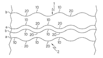
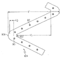
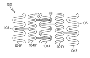
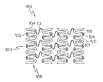
多くのステントは、正弦波形状に似たジグザグ形状、または蛇行性形状の支柱を備えて製造される。ステントの蛇行性部分の例としては図4aの符号104に示されている。蛇行性部分104はステントの周囲に伸びて、隣接する支柱間に伸びる複数個の屈曲部105を含んでいる。個々の支柱はステントの縦軸101に対して角度θ1で配置している。単数または複数の蛇行性部分104を含むステントが、図4bに示すように膨張していない状態から膨張した状態へと放射状に膨張する際には、支柱の角度θ2は縦軸に対して増加して有効支柱長さはLからL−ΔLに減少し、結果としてステントが短くなってしまう。
Many stents are manufactured with zigzag or serpentine-shaped struts resembling a sinusoidal shape. An example of a serpentine portion of the stent is shown at 104 in FIG. 4a. The
しかし、配置の途中でステントが短くなることは、ステントの配置精度を低下させてしまうことから望ましいことではない。 However, shortening the stent during the placement is not desirable because it reduces the placement accuracy of the stent.
さらに、病状を治すために患者の体内に薬を投与することは、通常は望ましいことである。特に、冠動脈系の治療には多くの薬物治療がそれ単独で、または他の侵襲的処置と合わせて有効である。 In addition, it is usually desirable to administer drugs into a patient's body to cure a medical condition. In particular, many medications are effective for treating the coronary system alone or in combination with other invasive procedures.
かかる治療は、ニトログリセリンやエピネフリン、リドカインなどの薬物を冠動脈系治療のために心内膜や心膜腔へ送ることを含んでいる。加えて、ヘパリンやヒルジン、レオプロ(登録商標)や他の抗血栓剤複合物が、閉塞した冠状動脈や心臓血管系の他の場所などの冠動脈系と関連する血管へ注入されることもある。さらに最近では、例えば遺伝子物質の導入などの遺伝子治療、例えばタンパク質、細胞、脈管成長因子を含む媒介動物の導入などの成長因子治療が、例えば、新しい血管に発達し得る新生血管導管の成長を刺激することによって、虚血心細胞組織や他の冠動脈系領域の治療に潜在的利益を与えるためにおこなわれている。 Such treatment involves sending drugs such as nitroglycerin, epinephrine, lidocaine to the endocardium or pericardial space for coronary treatment. In addition, heparin, hirudin, Leopro® and other antithrombotic compounds may be injected into blood vessels associated with the coronary system, such as occluded coronary arteries and other locations in the cardiovascular system. More recently, gene therapy, such as the introduction of genetic material, for example, growth factor therapy, such as the introduction of vector animals, including proteins, cells, vascular growth factors, has led to the growth of neovascular conduits that can develop into new blood vessels Stimulation has been done to provide potential benefits for the treatment of ischemic heart cell tissue and other coronary arterial areas.
また、脈管構造に薬物を伝達させるために様々な方法が適用されている。例えば、多孔質潅流風船、および/または、継続的または断続的な局所的配送を改善するための電極および/または電熱線で、第一電極は潅流風船内に備えられ、第二電極は動脈付近の患者の体の外部に備えられてなるイオン泳動、カテーテル壁に薬物を埋め込んだり挿入したりすること、カテーテル上の無孔風船壁および/またはカテーテルの被覆などを任意に備えた注入カテーテルなどが含まれている。 Various methods have also been applied to transfer drugs to the vasculature. For example, a porous perfusion balloon and / or an electrode and / or heating wire to improve continuous or intermittent local delivery, the first electrode is provided within the perfusion balloon and the second electrode is near the artery Iontophoresis provided outside the patient's body, implanting or inserting a drug into the catheter wall, an infusion catheter optionally equipped with a non-porous balloon wall on the catheter and / or a catheter covering, etc. include.
他の薬物配送方法としてはステントを使用することである。例えば、米国特許第6258121号では、包含活性剤を解放可能な高分子被覆を有するステントが記載されている。 Another drug delivery method is to use a stent. For example, US Pat. No. 6,258,121 describes a stent having a polymeric coating that can release an included active agent.
発明の範囲を限定することなく、本発明の概要を以下に示している。また、発明の概要の実施形態のさらなる詳細および/または発明のさらなる実施形態は以下、発明の詳細な説明で見ることができる。 Without limiting the scope of the invention, an overview of the invention is given below. Further details of the summary embodiments of the invention and / or further embodiments of the invention may be found in the detailed description of the invention below.
本発明の一実施形態としては、第一側および第二側を備えた支柱を有し、各側は交互に山と谷を有しているステントである。第一側の山は第二側の谷と並んでいる。ステントはさらに少なくとも一つの隣接支柱を有しており、該隣接支柱は、第一側および第二側を有しており、各側は交互に山と谷を有している。隣接支柱の第一側の山は、隣接支柱の第二側の谷と並んでいる。さらに、はじめの支柱の第一側の山と隣接支柱の第二側の山は並んでおり、はじめの支柱の第一側の谷と隣接支柱の第二側の谷は並んでいる。 One embodiment of the present invention is a stent having struts having a first side and a second side, each side having alternating peaks and valleys. The first mountain is lined with the second valley. The stent further has at least one adjacent strut, the adjacent strut having a first side and a second side, each side having alternating peaks and valleys. The mountain on the first side of the adjacent column is aligned with the valley on the second side of the adjacent column. Furthermore, the first side crest of the first column and the second side crest of the adjacent column are arranged, and the first side valley of the first column and the second side valley of the adjacent column are arranged.
一実施形態としては、支柱が波紋状を呈している実施形態がある。 As one embodiment, there is an embodiment in which the support column has a ripple shape.
他の実施形態としては、支柱が、並んでいる第一側の山と第二側の谷の間に少なくとも一つの形成された陥凹を有する実施形態である。第一側の山と第二側の谷の各並びは、隣接支柱と同様に、形成された陥凹を有していることが好ましい。形成された陥凹は、解放場所までステントを介して配送される治療薬剤を保持するために使用できる。形成された陥凹は、隣接支柱と同様に、第一側の山と第二側の谷のそれぞれの間に配されるのが望ましい。かかる構造は、ステント強度を損なうことなく、最大の薬物量の配送を可能としている。 In another embodiment, the strut has at least one formed recess between the side-by-side first side crest and second side trough. Each row of the first side crest and the second side trough preferably has a formed recess, similar to the adjacent struts. The formed recess can be used to hold a therapeutic agent that is delivered through the stent to the release site. It is desirable that the formed recess is arranged between each of the first side crest and the second side trough, like the adjacent support column. Such a structure allows for maximum drug delivery without compromising stent strength.
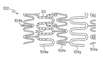
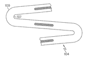
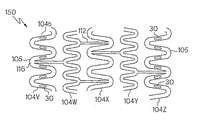
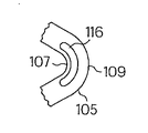
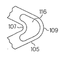
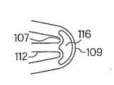
他の実施形態としては、ステントの外周に伸びる蛇行性部分を有するステントである。蛇行性部分は、複数の屈曲部を有する第一端と、複数の屈曲部を有する第二端と、それらの間に伸びる支柱とを有している。第一端および第二端の屈曲部の少なくとも一つおよび/または支柱のいくつかは、そこに伸びる十分に包囲された切欠き領域を有しており、および/または、まったく伸びておらず、むしろ3面は包囲されていて天井が開いているように形成された陥凹を有している。該形成された陥凹は、支柱の屈曲部よりも大きさとしては小さいものである。 Another embodiment is a stent having a serpentine portion that extends around the outer periphery of the stent. The serpentine portion has a first end having a plurality of bent portions, a second end having a plurality of bent portions, and a column extending between them. At least one of the bends at the first end and the second end and / or some of the struts have a well-enclosed cutout region extending there and / or not extending at all, Rather, the three sides are surrounded and have a recess formed so that the ceiling is open. The formed recess is smaller in size than the bent portion of the column.
ステントは、該ステントの外周に伸びる複数の蛇行性部分を有し、各蛇行性部分が第一端および第二端に複数の屈曲部を有しているのが好ましい。各蛇行性部分の第一端および第二端の屈曲部の少なくともいくつかは、そこに伸びて十分に包囲された切欠き領域、または全く伸びない形成された陥凹を有しているのが好ましい。より好ましくは、蛇行性部分の各端部の各屈曲部が、そこに伸びる切欠き領域および/または全く伸びない形成された陥凹を有していることである。 The stent preferably has a plurality of serpentine portions extending on the outer periphery of the stent, and each serpentine portion has a plurality of bent portions at the first end and the second end. At least some of the bends at the first end and the second end of each serpentine portion have a notch region that extends and is fully enclosed therewith, or a recess that is not extended at all. preferable. More preferably, each bend at each end of the serpentine portion has a cutout region extending there and / or a recess formed that does not extend at all.
発明にかかるステントとしては、以下の実施形態がある。すなわち、ステントの近接端に近接蛇行性部分を有し、ステントの遠心端に遠心蛇行性部分を有し、そこには、少なくとも一つの、好ましくは近接蛇行性部分と遠心蛇行性部分の双方が、そこに伸びる切欠き領域および/または全く伸びない形成された陥凹を備えた複数の屈曲部を有する実施形態である。 The stent according to the invention includes the following embodiments. That is, it has a proximal serpentine portion at the proximal end of the stent and a centrifugal serpentine portion at the distal end of the stent, where there is at least one, preferably both the proximal and centrifugal serpentine portions. , An embodiment having a plurality of bends with notched regions extending therein and / or formed recesses that do not extend at all.
発明にかかるステントの蛇行性部分の屈曲部のいくつかは、切欠き領域および/または形成された陥凹を有しており、または屈曲部のすべてが切欠き領域および/または形成された陥凹を有している場合もある。一実施形態としては、屈曲部の一つおきごとに切欠き領域および/または形成された陥凹を有している実施形態もある。 Some of the bends of the serpentine portion of the inventive stent have notches and / or formed recesses, or all of the bends are notched and / or formed recesses. May have. In some embodiments, every other bend has a cutout region and / or a recess formed.
ある実施形態においては、支柱のいくつか、またはすべてが形成された陥凹を有している実施形態もある。各支柱は、単数または複数の形成された陥凹を有することができる。ある実施形態では、第一端および/または第二端における屈曲部のいくつかが形成された陥凹を有する場合もある。各屈曲部は、一つのみの形成された陥凹を有する場合もあるし、複数の形成された陥凹を有する場合もある。 In some embodiments, some or all of the struts have recesses formed therein. Each strut can have one or more formed recesses. In some embodiments, some of the bends at the first end and / or the second end may have a recess formed therein. Each bent portion may have only one formed recess, or may have a plurality of formed recesses.
本発明では、切欠き領域および/または支柱が一定形状または不規則形状を呈している。 In the present invention, the notch region and / or the strut has a constant or irregular shape.
本発明のある実施形態では、各屈曲部は切欠き領域および/または形成された陥凹を有しており、該屈曲部は第一幅を有する内側屈曲部と、第一幅よりも広い第二幅を有する外側屈曲部を有している。切欠き領域および/または形成された陥凹は、内側屈曲部と外側屈曲部の間に配されている。本発明の他の実施形態としては、各屈曲部は切欠き領域および/または形成された陥凹を有しており、該屈曲部は第一幅を有する内側屈曲部と、第一幅よりも狭い第二幅を有する外側屈曲部を有している。また他の実施形態としては、第一幅と第二幅が等しい実施形態もある。 In an embodiment of the present invention, each bent portion has a notch region and / or a formed recess, and the bent portion has an inner bent portion having a first width and a first width wider than the first width. It has an outer bend having two widths. The notch region and / or the formed recess is arranged between the inner and outer bends. In another embodiment of the present invention, each bent portion has a notch region and / or a formed recess, and the bent portion has an inner bent portion having a first width, and an inner bent portion having a first width. It has an outer bend having a narrow second width. As another embodiment, there is an embodiment in which the first width and the second width are equal.
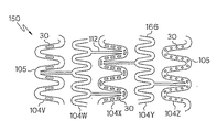
ここで開示される発明にかかるステントは、該ステントの長手方向にわたって、蛇行性部分ごとの切欠き領域および/または形成された陥凹の数が多様である実施形態として提供されるものである。一つの端部において少なくとも一つの蛇行性部分を有することが望ましいが、より好ましくは、ステントの両端がステントの中間部分の蛇行性部分よりも多くの切欠き領域および/または形成された陥凹を有することである。 The stent according to the invention disclosed herein is provided as an embodiment in which the number of the notch regions and / or the number of depressions formed in the meandering portions varies along the longitudinal direction of the stent. It is desirable to have at least one serpentine portion at one end, but more preferably, both ends of the stent have more notch regions and / or formed recesses than the serpentine portion of the middle portion of the stent. Is to have.
ここで開示される発明にかかるステントはまた、該ステントの長手方向にわたって、蛇行性部分における切欠き領域および/または形成された陥凹の大きさが多様である実施形態として提供されるものである。一つの端部において少なくとも一つの蛇行性部分を有することが望ましいが、より好ましくは、ステントの両端がステントの中間部分の蛇行性部分よりも大きな切欠き領域および/または形成された陥凹を有することである。 The stent according to the invention disclosed herein is also provided as an embodiment in which the size of the notch region and / or the recess formed in the meandering portion varies in the longitudinal direction of the stent. . It is desirable to have at least one serpentine portion at one end, but more preferably, both ends of the stent have a larger cutout area and / or formed recess than the serpentine portion of the middle portion of the stent. That is.
ある実施形態では、本発明はステント外周に伸びる複数の蛇行性部分を有する放射状に膨張可能なステントとして示されており、各蛇行性部分は複数の屈曲部を有しており、そこでは屈曲部の少なくともいくつかはそこで伸びる十分に包囲された切欠き領域を備えている。切欠き領域は、ステントが非画一的に開くようにステント周りに配されている。一実施形態としては、ステントは該ステントの近接端に近接蛇行性部分を、ステントの遠心端に遠心蛇行性部分を、ステントの中間部分に先行してステントの近接端および遠心端の一方または双方が開くようにステントの近接端および遠心端と切欠き領域の間に中間部分をそれぞれ配している実施形態である。他の実施形態としては、ステントの両端の一方または双方に先行して該ステントの中間部分が開くように、切欠き領域が配されている実施形態もある。切欠き領域はステントが膨張する前は実質的には弓形であるのが典型的であるが、他の形態の切欠き領域が使用される場合もある。各蛇行性部分の各屈曲部は切欠き領域を有しているのが好ましい。これらの実施形態では、切欠き領域と任意に組み合わされ得る治療薬剤の配送のための陥凹により、非画一的に開くステントや治療薬剤を配送するステントを提供することができる。 In one embodiment, the present invention is shown as a radially expandable stent having a plurality of serpentine portions extending around the stent periphery, each serpentine portion having a plurality of bends, wherein the bends are At least some of them have a fully enclosed cutout region extending there. The notch region is arranged around the stent so that the stent opens non-uniformly. In one embodiment, the stent has a proximal serpentine portion at the proximal end of the stent, a centrifugal serpentine portion at the distal end of the stent, and one or both of the proximal and distal ends of the stent preceding the intermediate portion of the stent. In the embodiment, an intermediate portion is disposed between the proximal end and the distal end of the stent and the cut-out region so as to open. In other embodiments, a notched region is provided such that the middle portion of the stent opens prior to one or both ends of the stent. The notched area is typically substantially arcuate before the stent expands, although other forms of notched areas may be used. Each bent portion of each serpentine portion preferably has a notch region. In these embodiments, a recess for delivery of a therapeutic agent that can be arbitrarily combined with a notched region can provide a non-uniformly open stent or a stent that delivers a therapeutic agent.
本発明はさらに、第一端および第二端を有する少なくとも一つのチューブ状の蛇行性部材を有しているステントを示すものである。蛇行性部材は、第一端に複数の屈曲部を有し、第二端に複数の屈曲部を有し、それらの間に伸びる支柱を有している。ある実施形態では、第一端および第二端の各屈曲部は十分に包囲されてそこに伸びる切欠き領域を有している。また、ある実施形態では、第一端および第二端の各屈曲部および/または支柱が、形成された陥凹を有している。ステントは、隣接するチューブ状の蛇行性部材と相互に連結する複数のチューブ状の蛇行性部材を有している。十分に包囲された切欠き領域を有するこれらの実施形態においては、十分に包囲された切欠き領域の形状がステントの膨張時に変化するのが好ましい。より好ましくは、十分に包囲された切欠き領域がステントの膨張していない形状の際には第一面積によって規定され、ステントが膨張した形状の際には第一面積よりも大きな第二面積によって規定される実施形態である。 The present invention further shows a stent having at least one tubular serpentine member having a first end and a second end. The meandering member has a plurality of bent portions at a first end, a plurality of bent portions at a second end, and a support column extending between them. In one embodiment, each bend at the first end and the second end has a notch region that is fully enclosed and extends therethrough. Moreover, in one embodiment, each bending part and / or support | pillar of a 1st end and a 2nd end have the formed recess. The stent has a plurality of tubular serpentine members interconnected with adjacent tubular serpentine members. In those embodiments having a fully enclosed cutout region, the shape of the fully enclosed cutout region preferably changes upon expansion of the stent. More preferably, the fully enclosed notch region is defined by a first area when the stent is in an unexpanded shape and by a second area that is larger than the first area when the stent is in an expanded shape. It is an embodiment defined.
発明にかかるステントはまた、以下の実施形態において提供され得る。すなわち、十分に包囲された切欠き領域および/または形成された陥凹がステントが膨張していない形状の際には第一幅で規定され、ステントが膨張した形状の際には第一幅よりも大きな第二幅で規定されるという実施形態である。 An inventive stent can also be provided in the following embodiments. That is, the fully-enclosed notch region and / or the formed recess is defined by the first width when the stent is not expanded, and the first width when the stent is expanded. Is an embodiment that is also defined with a large second width.
発明にかかるステントの切欠き領域および/または形成された陥凹は、ステントが非膨張状態の際には弓形であるのが典型的である。尤も、ここではその他の切欠き領域および/または形成された陥凹の形状も開示されてはいるが。 The notched areas and / or formed recesses of the inventive stent are typically arcuate when the stent is in an unexpanded state. However, other notch regions and / or shapes of formed recesses are also disclosed here.
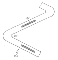
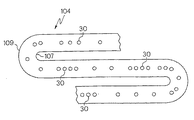
他の実施形態として、本発明はステント外周に伸びる蛇行性部分を有するステントを示しているが、かかる蛇行性部分は第一端および第二端を有しており、第一端は複数の屈曲部を有し、第二端は複数の屈曲部を有し、それらの間に伸びる支柱を有しており、第一端の少なくとも一つの屈曲部において、第二端の少なくとも一つの屈曲部において、それらの間の少なくとも一つの支柱において、またはそれらの組み合わせにおいては、複数の形成された陥凹を有しているステントである。 In another embodiment, the present invention shows a stent having a serpentine portion extending around the outer periphery of the stent, the serpentine portion having a first end and a second end, the first end having a plurality of bends. The second end has a plurality of bends and has a strut extending therebetween, at least one bend at the first end, at least at one bend at the second end A stent having a plurality of formed recesses, in at least one strut therebetween, or in a combination thereof.
形成された陥凹はいかなる形状であってもよい。ある実施形態では、形成された陥凹は実質的に円形であったり、楕円形であったりする場合がある。 The formed recess may have any shape. In certain embodiments, the formed recess may be substantially circular or elliptical.
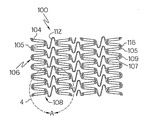
本発明はまた、ここで開示される発明にかかるステントのいずれかとカテーテルの組み合わせを示すものでもある。ステントは、近接端および遠心端と複数の相互接続された蛇行性ベルトを有するものであるが、該蛇行性ベルトは、複数の切欠き領域および/または、蛇行性ベルトの屈曲部または蛇行性ベルトの支柱に位置する形成された陥凹を有している。切欠き領域および/または形成された陥凹を有する単数または複数の蛇行性ベルト周りには固定スリーブが配されている。 The present invention also illustrates a combination of any of the stents disclosed herein and a catheter. The stent has a proximal end and a distal end and a plurality of interconnected serpentine belts, the serpentine belt comprising a plurality of notch regions and / or bends or serpentine belts of the serpentine belt. And has a recess formed in the post. A securing sleeve is disposed around the meandering belt or belts having the cutout area and / or the recesses formed.
本発明のある実施形態としては、ステントの骨格を形成する連結部材および支柱を有する典型的なステント構造のステントがある。かかるステントの骨格はさらに、患者の体内に配送される薬剤や麻薬を保持する貯蔵所を提供する形成された陥凹を有している。かかる形成された陥凹は様々な構造または形状であり、様々な深度や大きさ、例えば幅や長さや外周を有している。さらに、ステント骨格に配される形成された陥凹の数もまた多様である。かかる実施形態においては、ステントは薬剤や麻薬を体内の目標位置に配送するために設計されている。さらには、ある実施形態において、本発明のステントは、限定するものではないが、以下のような治療薬剤を患者の脈管構造に配送されるように設計されている。すなわち、治療薬剤としては、遺伝子物質、成長因子、抗新生物質、抗有糸分裂、抗炎症薬、抗血小板物質、抗凝血剤、抗線維素、アンチトロンビン、抗増殖性物質、抗生物質、酸化防止剤、抗アレルギー性薬剤などやそれらの組み合わせなどである。本発明は薬剤が体内の目標位置または体内の選択された細胞組織領域に直接沈積されることを可能とするものである。 One embodiment of the present invention is a stent with a typical stent structure having connecting members and struts that form the backbone of the stent. Such stent scaffolds further have formed recesses that provide a reservoir to hold drugs and narcotics delivered to the patient's body. Such formed recesses have various structures or shapes, and have various depths and sizes, such as width, length, and outer periphery. In addition, the number of recesses formed in the stent framework is also diverse. In such embodiments, the stent is designed to deliver drugs and narcotics to target locations within the body. Further, in certain embodiments, the stent of the present invention is designed to deliver a therapeutic agent such as, but not limited to, the following therapeutic agents to the patient's vasculature. That is, therapeutic agents include genetic substances, growth factors, anti-neoplastic substances, anti-mitotics, anti-inflammatory drugs, antiplatelet substances, anticoagulants, antifibrin, antithrombin, antiproliferative substances, antibiotics, Antioxidants, antiallergic drugs and combinations thereof. The present invention allows the drug to be deposited directly at a target location within the body or at selected cellular tissue regions within the body.
そのために、本発明のステントは該ステントの骨格中に切欠きや形成された陥凹、またはそれらの組み合わせを有するものである。 Therefore, the stent of the present invention has a notch or a recess formed in the stent skeleton, or a combination thereof.
本発明のさらなる詳細および/または実施形態は以下で論じられている。 Further details and / or embodiments of the invention are discussed below.
本発明は様々な形態で実施され得るが、ここでは本発明のより好ましい実施形態を詳細に説明している。この説明は発明の本質を例示したものであるが、説明された特定の実施形態に発明を限定する意味ではない。 While the invention may be embodied in many different forms, there are described in detail herein more preferred embodiments of the invention. This description is an exemplification of the nature of the invention but is not meant to limit the invention to the particular embodiments described.
本開示において、図の参照番号は、他の示唆がない場合にはその外観を示すものである。また、本開示において、切欠き領域とは、ステント材質に包囲された開口を有するステントの蛇行性部分の領域を示している。切欠き領域とは、切欠くといった特定のステント形成方法を意味するものではなく、むしろ切欠き領域においてステントが存在しないことを示すものである。 In this disclosure, reference numerals in the figures indicate their appearance when there is no other suggestion. In the present disclosure, the notch region indicates a region of the meandering portion of the stent having an opening surrounded by the stent material. The notched region does not mean a specific stent formation method such as notching, but rather indicates that no stent is present in the notched region.
さらに、本開示において、形成された陥凹とは、開口を有していないステントの蛇行性部分の領域を示しており、様々な深度のステント材質における陥凹のことを示すものである。この形成された陥凹とは、以下、治療薬などの薬剤を保持するために使用され得る貯蔵所であるステントの蛇行性部分の領域を包含するものとして使用され、また、溝や経路、隙間、段、孔などで記載され得るものを包含するものとして使用される。形成された陥凹はいかなる形状であってもよい。特定形状としては、引き延ばされた楕円形、実質的に円形の陥凹、楕円、長方形、正方形、三角形などを包含するものである。以下、実質的に円形とは、楕円などを包含するものとして使用される。 Furthermore, in the present disclosure, the formed recess indicates a region of the meandering portion of the stent that does not have an opening, and indicates a recess in the stent material at various depths. This formed recess is used below to encompass the area of the tortuous portion of the stent, which is a reservoir that can be used to hold a drug such as a therapeutic agent, and also includes grooves, pathways and gaps. , Including those that can be described by steps, holes, and the like. The formed recess may have any shape. Specific shapes include elongated ellipses, substantially circular depressions, ellipses, rectangles, squares, triangles, and the like. Hereinafter, “substantially circular” is used to encompass an ellipse and the like.
これらの形成された陥凹は、様々な深度で全く延びることのないステントの蛇行性部分の領域である。上記するステント材質とは、本発明の切欠き、または形成された陥凹に提供される治療薬を示すものではない。 These formed depressions are regions of the tortuous portion of the stent that do not extend at all at various depths. The above-mentioned stent material does not indicate a therapeutic agent provided in the notch or formed recess of the present invention.
一般に、本発明は、例えばニチノール(登録商標)などのニッケルチタニウム形状記憶合金のような形状記憶合金や、ステンレス鋼などを含む適当なステント材質でできた放射状に膨張可能なステントを提供するものである。ステントは、ステントの円筒形輪郭と外接する円周方向のセグメントとして作用する一連の支柱を包含している。それぞれのステントはステントの円筒形輪郭の中心軸に垂直な分離した面が並んでいる。ステントは、該ステントを形成するために相互に結合する様々に異なった多数の支柱を有している。 In general, the present invention provides a radially expandable stent made of a suitable stent material including, for example, a shape memory alloy such as nickel titanium shape memory alloy such as Nitinol®, or stainless steel. is there. The stent includes a series of struts that act as circumferential segments circumscribing the cylindrical contour of the stent. Each stent is lined with a separate plane perpendicular to the central axis of the cylindrical profile of the stent. Stents have a number of different struts that are joined together to form the stent.
本発明の一つの実施形態として、各支柱が第一側と第二側を有し、各側が各支柱の長手方向に沿って谷と山を交互に備えた一連の屈曲を備えている。各支柱の第一側の山は各支柱の第二側の谷と並んでいる。 As one embodiment of the present invention, each strut has a first side and a second side, and each side comprises a series of bends with alternating troughs and peaks along the longitudinal direction of each strut. The first mountain of each column is aligned with the second valley of each column.
支柱は相互に隣接している。各隣接支柱は第一側および第二側を有し、各側は各支柱の長手方向に交互に谷と山をもった一連の屈曲部を有している。支柱の第一側の谷は隣接支柱の第二側の谷と並んでおり、支柱の第一側の山は隣接支柱の第二側の山と並んでいる。 The struts are adjacent to each other. Each adjacent column has a first side and a second side, and each side has a series of bends with valleys and peaks alternately in the longitudinal direction of each column. The valley on the first side of the column is aligned with the valley on the second side of the adjacent column, and the peak on the first side of the column is aligned with the peak on the second side of the adjacent column.
各支柱の大きさは様々である。さらに、支柱から支柱までの大きさも様々である。かかる大きさは、各谷の底と各山の頂上との距離によって決定され、支柱が放射状に膨張して大きさが減少した際には変更される。 The size of each strut varies. Furthermore, the size from the support to the support is also varied. The size is determined by the distance between the bottom of each valley and the top of each mountain, and is changed when the column expands radially and decreases in size.
縦方向に隣接した支柱は相互に連結部材で結合されている。様々な実施形態において、かかる連結部材は実質上、線形、U字形、V字形、S字形などである。 The struts adjacent in the vertical direction are connected to each other by a connecting member. In various embodiments, such connecting members are substantially linear, U-shaped, V-shaped, S-shaped, and the like.
図を見ると、図1aには本発明の実施形態が図示されている。支柱1は、第一側aと第二側bを有し、支柱2は第一側aと第二側bを有している。加えて、各支柱は山10と谷20を有している。支柱1の第一側aの山10は、支柱1の第二側の谷20と並んでいる。隣接する支柱2の第二側bの山は支柱1の第一側aの山10と並んでおり、隣接する支柱2の第二側bの谷20は隣接する支柱2の第一側aの谷20と並んでいる。上述するように大きさは様々である。
Turning to the figures, FIG. 1a illustrates an embodiment of the present invention. The support column 1 has a first side a and a second side b, and the
図1bは図1aのステントが膨張した状態を図示している。加えて、連結部材12,14が縦方向に隣接する支柱間に見られる。
FIG. 1b illustrates the expanded state of the stent of FIG. 1a. In addition, the connecting
図1cは、支柱形状の異なる形態を図示したものであり、バンド15,17が図1bに示されたバンド13,14に置換されている。バンド16はまた、本発明の改良された支柱の形態に置換され得る。さらには、バンド15,16および/または17の組み合わせは本発明で記載されるような支柱形態に置換され得る。
FIG. 1c illustrates a different form of column shape, with bands 15 and 17 being replaced by
図2aは本発明の他の実施形態を図示したものであるが、実質的には各支柱1,2において、円形陥凹30が並んだ山10と谷20の間に位置している。本発明では、形成された陥凹30は治療薬を収容するために適度に使用される。
FIG. 2 a illustrates another embodiment of the present invention, which is substantially located between the
ステントに使用される陥凹の量や陥凹の大きさ、深度はすべて、体内に挿入される薬物量の調整に応じて多様である。陥凹は縮んでいる間は薬物が妨げられるのを防ぐことに関与し、薬物は表面下に置かれているために、薬物は除去されることなく目標位置へ配送されることとなる。 The amount of depression, the size and depth of the depression used in the stent all vary depending on the amount of drug inserted into the body. The recess is responsible for preventing the drug from being blocked while it is contracting, and because the drug is placed under the surface, the drug will be delivered to the target location without being removed.
上記実施形態では、陥凹が支柱から支柱へ千鳥配置となるステント構造である。かかる実施形態は、ステント自体の全体の状態を損なうことなく、薬物配送に有効な表面積の極大化を可能とするものであるために望ましいものである。 In the above embodiment, the stent structure is a staggered arrangement of the recesses from the support column to the support column. Such an embodiment is desirable because it allows the maximization of the effective surface area for drug delivery without compromising the overall condition of the stent itself.
かかる方法で配送され得る薬物は、患者の体内にうまく配送される、特に体内の目標位置にうまく配送され得るあらゆる薬物を含むものである。この薬物の例としては、限定するものではないが、麻薬や放射性物質を含む治療薬などが挙げられる。治療薬とは、限定するものではないが、ここでは以下のものを含んでいる。すなわち、アンチトロンビン、抗増殖性物質、麻酔薬、抗線維素、抗凝血剤、抗新生物薬/抗増殖性物質/抗凝瞳薬、成長因子阻害薬、転写活性化因子、並進阻害薬を含む脈管細胞成長阻害薬(例えば、タンパク質、血管成長因子を含む細胞や媒介動物)、成長因子抑制剤を含む脈管細胞成長抑制剤、成長因子受容体抑制因子、転写活性化抑制体、並進抑制体、複製抑制剤、抑制抗体、成長因子に対抗する抗体、成長因子や細胞毒素からなる二官能性分子、抗体や細胞毒素からなる二官能性分子、クロレステロル(chlolesterol)低減薬、血管拡張薬、遺伝子治療用の遺伝子物質、血小板受容体抑制因子、抗血小板受容体抗体のような抗血小板薬、プロスタグランジン阻害薬、血小板阻害薬、ダニ抗血小板ペプチド、抗体、内因性血管作用構造の妨げとなる薬などのことである。 Drugs that can be delivered in such a manner include any drug that can be successfully delivered into the patient's body, and in particular, can be delivered to a target location within the body. Examples of this drug include, but are not limited to, narcotics and therapeutic agents containing radioactive substances. The therapeutic agent includes, but is not limited to, the following. Antithrombin, antiproliferative substance, anesthetic, antifibrin, anticoagulant, antineoplastic / antiproliferative / anticoagulant, growth factor inhibitor, transcription activator, translation inhibitor Vascular cell growth inhibitors (e.g., proteins and cells containing vascular growth factors and vectors), vascular cell growth inhibitors including growth factor inhibitors, growth factor receptor inhibitors, transcription activation inhibitors, Translation inhibitor, replication inhibitor, inhibitory antibody, antibody against growth factor, bifunctional molecule consisting of growth factor and cytotoxin, bifunctional molecule consisting of antibody and cytotoxin, chloresterol reducing drug, vasodilator Drugs, genetic material for gene therapy, platelet receptor inhibitory factor, antiplatelet drugs such as antiplatelet receptor antibody, prostaglandin inhibitor, platelet inhibitor, tick antiplatelet peptide, antibody, endogenous Drugs that might interfere with the vasoactive structure is that such.
アンチトロンビン、抗凝血剤、抗血小板物質、抗線維素の例としては、限定するものではないが、マサチューセッツ州ケンブリッジ市のバイオジェン社によるアンジオマックス(ANGIOMAX)(登録商標)などのトロンビン阻害薬や、D−phe−pro−argクロロメチルケトン(合成アンチスロンビン)、デキストラン、プロスタサイクリン、プロスタサイクリンアナログ、ナトリウムヘパリン、ヘパリンやヘパリン派生物、ヘパリノイド、ヒルジン、遺伝子組み替えヒルジン、糖タンパクIIb/IIIa血小板膜受容体抑制因子抗体、プロスタサイクリン、プロスタサイクリンアナログ、アルガトロバン(argatroban),フォースコリン(forskolin),バピプロスト(vapiprost)、ジピリダモール、ウロキナーゼ、ピーパック(pPack)(デキストロフェニルアラニン、プロリン、アルギニン、クロロメチルケトン)、RGCペプチド含有化合物、血小板受容体抑制因子、アンチトロンビン抗体、抗血小板受容体、抗体、アスピリン、プロスタグランジン阻害薬、血小板阻害薬、ダニ抗血小板ペプチドなどである。 Examples of antithrombin, anticoagulants, antiplatelet substances, antifibrin include, but are not limited to, thrombin inhibitors such as ANGIOMAX® by Biogen of Cambridge, Massachusetts D-phe-pro-arg chloromethyl ketone (synthetic antithrombin), dextran, prostacyclin, prostacyclin analog, sodium heparin, heparin and heparin derivatives, heparinoid, hirudin, genetically modified hirudin, glycoprotein IIb / IIIa Platelet membrane receptor inhibitory factor antibody, prostacyclin, prostacyclin analog, argatroban, forskolin, vapiprost, dipyridamole Urokinase, peapack (dextrophenylalanine, proline, arginine, chloromethyl ketone), RGC peptide-containing compound, platelet receptor inhibitor, antithrombin antibody, antiplatelet receptor, antibody, aspirin, prostaglandin inhibitor Platelet inhibitors, tick antiplatelet peptides, and the like.
細胞増殖抑制薬や抗増殖性薬の例としては、限定するものではないが、エノザプリン(enoxaprin)、アンギオペプチン(angiopeptin)、ブリストルマイヤーズスクイーズ社から入手可能なカポテン(CAPOTEN)(登録商標)やカポザイド(CAPOZIDE)(登録商標)を含むカプトプリルなどの酵素阻害薬を変換するアンギオテンシン、シラザプリル(cilazapril)や、ニュージャージー州ホワイトハウスステーションのメルクアンドカンパニー社から入手可能なプリニビル(PRINIVIL)(登録商標)やプリニザイド(PRINIZIDE)(登録商標)などのリシノプリル、ニフェジピンなどのカルシウムチャンネル遮断薬、コルヒチン、筋細胞増殖を遮断可能なモノクローナル抗体、ヒルジンや遺伝子組み替えヒルジン、アセチルサリチル酸、線維芽細胞増殖因子抑制因子、魚油(オメガ3脂肪酸)、ヒスタミン抑制因子、ロバスタチン(抗線維素の阻害薬や、メルクアンドカンパニー社からメバコール(MEVACOR)(登録商標)の商品名として入手可能なコレステロール低減薬であるHMG−CoA還元酵素阻害薬、ナトリウムヘパリンを含むアンチトロンビン、ヘパリンやヘパリン派生物、ヘパリノイド、ヒルジンや遺伝子組み替えヒルジン、アルガトロバン(argatroban)、フォースコリン(forskolin)、バピプロスト(vapiprost)、プロスタサイクリンやプロスタサイクリンアナログ、デキストラン、ジピリダモール、D−phe−pro−argクロロメチルケトン(合成アンチスロンビン)、糖タンパクIIb/IIIa血小板膜受容体抑制因子抗体など、バイオジェン社によるアンジオマックス(ANGIOMAX)(登録商標)などのトロンビン阻害薬、プロスタグランジン阻害薬、セロトニン遮断薬、ステロイド、チオプロティーズ阻害薬、血小板由来増殖因子抑制因子、一酸化窒素、血小板由来増殖因子受容体のようなモノクローナル抗体、ニトロプルシド、ホスホジエステラーゼ阻害薬、スラミン、セロトニン遮断薬、トリアゾロピリミジン(血小板由来増殖因子抑制因子)などである。 Examples of cytostatic and anti-proliferative drugs include, but are not limited to, enoxapurin, angiopeptin, capoten (registered trademark) available from Bristol-Myers Squeeze, Angiotensin, cilazapril, which converts enzyme inhibitors such as captopril, including capozide (registered trademark), and PRINIVIL (registered trademark) available from Merck & Company of White House Station, New Jersey, Prinizide (registered trademark) such as lisinopril, nifedipine and other calcium channel blockers, colchicine, monoclonal antibody capable of blocking myocyte proliferation Hirudin, genetically modified hirudin, acetylsalicylic acid, fibroblast growth factor inhibitor, fish oil (omega 3 fatty acid), histamine inhibitor, lovastatin (antifibrin inhibitor, MEVACOR (registered trademark) from Merck & Company) HMG-CoA reductase inhibitors, sodium heparin-containing antithrombin, heparin and heparin derivatives, heparinoids, hirudin, recombinant hirudin, argatroban, fortholin ( forskolin, bapiprost, prostacyclin and prostacyclin analogs, dextran, dipyridamole, D-phe-pro-arg chloromethyl ketone (combined) Antithrombin), glycoprotein IIb / IIIa platelet membrane receptor inhibitory factor antibody, thrombin inhibitors such as ANGIOMAX (registered trademark) by Biogen, prostaglandin inhibitors, serotonin blockers, steroids, Thioproteins inhibitor, platelet-derived growth factor inhibitor, nitric oxide, monoclonal antibodies such as platelet-derived growth factor receptor, nitroprusside, phosphodiesterase inhibitor, suramin, serotonin blocker, triazolopyrimidine (platelet-derived growth factor inhibitor Factor).
抗炎症薬の例としては、限定するものではないが、デキサメタゾンやプレドニゾロン、コルチコステロン、ブデソニド(budesonide)、エストロゲン、サルファサラジン、メザラミンなどである。 Examples of anti-inflammatory drugs include, but are not limited to, dexamethasone, prednisolone, corticosterone, budesonide, estrogen, sulfasalazine, mezalamine and the like.
抗新生物薬/抗増殖性物質/抗凝瞳薬の例としては、限定するものではないが、コネチカット州のスタンフォードのブリストルマイヤーズスクイーズ社のタキソール(TAXOL)(登録商標)などのパクリタキセル、ドイツのフランクフルトにあるアベンティスのタキソテール(TAXOTERE)(登録商標)などのドセタキセル(docetaxel)、メトトレキサート、アザチオプリン、ビンクリスチン、ビンブラスチン、5フルオロウラシル、ニュージャージー州のピーパックにあるアップジョン社のアドリアマイシン(ADRIAMYCIN)(登録商標)のようなドキソルビシン塩酸塩、コネチカット州のスタンフォードのブリストルマイヤーズスクイーズ社のムタミシン(MUTAMYCIN)(登録商標)のようなマイトマイシン、シスプラチン、エポチロン(epothilones)、エンドスタチン(endostatin)、アンジオスタチン、チミジンキナーゼ阻害薬などである。 Examples of anti-neoplastic / antiproliferative / anti-coagulant drugs include, but are not limited to, paclitaxel such as Taxol® from Bristol-Myers Squeeze of Stanford, Connecticut, Germany Docetaxel, such as Aventis Taxotere (registered trademark) in Frankfurt, methotrexate, azathioprine, vincristine, vinblastine, 5 fluorouracil, Adriamycin (ADRIAMYCIN) from Peapack, NJ Doxorubicin hydrochloride, such as MUTAMYCIN (registered trademark) of Bristol-Myers Squeeze, Stamford, Connecticut Clarithromycin, cisplatin, epothilones (epothilones), endostatin (endostatin), is angiostatin, thymidine kinase inhibitors such as.
麻酔薬の例としては、限定するものではないが、リドカイン、ブピバカイン、ロピバカイン(ropivacaine)などがある。抗アレルギー薬の例としては、パーミロラスト(permirolast)カルシウムである。治療薬の他の例としては、限定するものではないが、アルファインターフェロンがある。 Examples of anesthetics include but are not limited to lidocaine, bupivacaine, ropivacaine, and the like. An example of an antiallergic agent is permirolast calcium. Other examples of therapeutic agents include, but are not limited to, alpha interferon.
本発明のステントを使用して患者の体内に置かれ得る遺伝子物質の例としては、限定するものではないが、アンチセンスDNAおよびRNA、tRNAやrRNAとコード化されたDNA、CD阻害薬を含む細胞周期阻害薬、チミジンキナーゼや細胞増殖を阻害するのに有効な他の薬物、骨形成タンパク質などである。骨形成タンパク質は、限定するものではないが、BMP−2、BMP−3、BMP−4、BMP−5、BMP−6(Vgr−1)、BMP−7(OP−1)、BMP−8、BMP−9、BMP−10、BMP−11、BMP−12、BMP−13、BMP−14、BMP−15、BMP−16などである。中でも、BMP−2、BMP−3、BMP−4、BMP−5、BMP−6、BMP−7を使用するのが好ましい。かかる二量体タンパク質は、ホモ二量体やヘテロ二量体、またはそれらの結合物、それらが単独で、またはそれらと骨形成タンパク質の川上または川下の効果を包含可能な他の分子との結合物として与えられ得る。例えば、ヘッジホッグタンパク質やそれらをコード化するDNAは骨形成タンパク質と組み合わされて使用され得る。 Examples of genetic material that can be placed in a patient's body using the stent of the present invention include, but are not limited to, antisense DNA and RNA, DNA encoded with tRNA and rRNA, and CD inhibitors. These include cell cycle inhibitors, thymidine kinase, other drugs effective to inhibit cell proliferation, and bone morphogenetic proteins. Bone morphogenetic proteins include, but are not limited to, BMP-2, BMP-3, BMP-4, BMP-5, BMP-6 (Vgr-1), BMP-7 (OP-1), BMP-8, BMP-9, BMP-10, BMP-11, BMP-12, BMP-13, BMP-14, BMP-15, BMP-16, and the like. Among these, BMP-2, BMP-3, BMP-4, BMP-5, BMP-6, and BMP-7 are preferably used. Such dimeric proteins can be homodimers or heterodimers, or conjugates thereof, either alone or in association with other molecules that can include upstream or downstream effects of bone morphogenetic proteins. It can be given as a thing. For example, hedgehog proteins and DNA encoding them can be used in combination with bone morphogenetic proteins.
体内の目標位置に置かれる細胞は、人間固有の細胞(自己の細胞または人間の細胞)である場合もあるし、動物の細胞(異種細胞)である場合もあるが、遺伝学的には、それらは上皮細胞の移植場所に大切なタンパク質をうまく配送するように設計されている。配送媒体は、当業者に周知の細胞の機能や実行可能性を維持するために、随時編成され得る。 The cells placed at the target location in the body can be human-specific (autologous cells or human cells) or animal cells (heterogeneous cells), but genetically, They are designed to successfully deliver important proteins to the epithelial cell transplant site. The delivery medium can be organized at any time to maintain cellular function and viability well known to those skilled in the art.
放射性同位体は、放射線治療における人工器官を使用する際に使用され得るが、限定するものではないものの、リン酸(H3P32O4)、パラジウム(Pd103)、セシウム(Cs131)、ヨウ素(I125)などを含んでいる。 Radioisotopes can be used when using prostheses in radiotherapy, but are not limited to phosphoric acid (H 3 P 32 O 4 ), palladium (Pd 103 ), cesium (Cs 131 ), Iodine (I 125 ) and the like are included.
上記の列挙は排他的なものではなく、典型的な目的のみを意図するものである。治療薬や他の薬物の予防や治療特性は通常の当業者には周知のものであり、上記の列挙は単に例示に過ぎず、本発明の範囲を制限する意図ではない。ここで列挙されていない他の治療薬や他の薬物も同様に使用することは可能であり、また当業者にも周知のことである。図2bの実施例は、膨張状態にある支柱1,2それぞれにおいて並んだ山10と谷20の間に位置する円形の陥凹30を実質的に備えた同一のステント構造を示している。
The above list is not exclusive and is intended for typical purposes only. The prophylactic and therapeutic properties of therapeutic agents and other drugs are well known to those of ordinary skill in the art, and the above list is merely illustrative and is not intended to limit the scope of the invention. Other therapeutic agents and other drugs not listed here can be used as well, and are well known to those skilled in the art. The embodiment of FIG. 2b shows the same stent structure with a substantially
図3aは、図2aで示されたステント構造の他の実施形態を図示したものであり、陥凹30は伸びた楕円形となっている。図3bは、膨張状態にある同一のステント構造を図示したものである。
FIG. 3a illustrates another embodiment of the stent structure shown in FIG. 2a, where the
本発明の他の実施形態としては、ステントが該ステントの周りに伸びる複数の蛇行性部分を備えることができる。本開示の目的は、蛇行性部分とは、限定するものではないが、ジグザグ形状のことである。蛇行性部分は、限定するものではないが、鋭角な屈曲部や緩やかな屈曲部を備えた形態を包含している。 In other embodiments of the present invention, the stent can comprise a plurality of serpentine portions extending around the stent. The purpose of the present disclosure is to mean, but not limited to, a zigzag shape. The meandering portion includes, but is not limited to, a form provided with an acute bent portion or a gentle bent portion.
図を参照すると、ステントの周りに伸びる複数の蛇行性部分を有する該ステントは、図6aでは100で示されている。蛇行性部分104は、該蛇行性部分の近接端および遠心端に複数の屈曲部105を有している。
Referring to the figure, the stent having a plurality of serpentine portions extending around the stent is shown at 100 in FIG. 6a. The
蛇行性部分104は単数または複数の連結部材112で一方と他方が接続されている。図6aに示すように、連結部材112は湾曲部と支柱を有している。ここで、支柱とは、直線形状やその他の曲線を含む形状の双方を包含するものとして使用され得る。連結部材112の第一端112aと第二端112bは相互に外周に分かれている。
One and the other of the meandering
図6a〜図8aで示されているように、蛇行性部分104の近接端106と遠心端108には、切欠き領域116が備えてある。該切欠き領域116はバンドの屈曲部105と実質的には同様の屈曲を有しており、内部の屈曲部107と外部の屈曲部109を明確にしている。切欠き領域116は、実質的に屈曲部105の半径に沿って伸びていることが望ましい。
As shown in FIGS. 6 a-8 a, the
図8aで示すように、蛇行性部分104の長手の全長はLで示されており、蛇行性部分の内側の半径間の距離はL1で示されている。切欠き部分の幅は、内側の屈曲部107と外側の屈曲部109の間の最大距離で決定されるが、L2で示されている。
As shown in FIG. 8a, the overall length of the
図9aで示すように、ステントの膨張時には、膨張した蛇行性部分104の長手の全長はL1’で示されており、Lよりもわずかに短くなっている。L1’で示されている、膨張時の蛇行性部分の内側半径間の距離の減少は、L2’で示されている、内側の屈曲部107と外側の屈曲部109の間の最大距離の増加によって相殺される。
As shown in FIG. 9a, when the stent is expanded, the full length of the expanded
さらに本発明のステントは、患者の体内に薬物を配送する際に使用するのが望ましく、特に体内の目標位置にうまく配送する際に好適である。図5aでは典型的なステント形状を100で図示しており、図5bでは、ステントの骨格を形成する連結部材112や蛇行性部分104を備えたステントを100で図示している。蛇行性部分104wは、治療薬のような薬物を保持するための貯蔵所を提供する実質的に円形で様々な深度の陥凹30を陳列している。図5bには図5aに示されたものと同じステントが示されているが、形成された陥凹は実質的に円形というよりは引き延ばされた楕円形で表されている。様々な深度の陥凹の例を示した側面図が、図5aや5bでは符号103で示されている。上記するように、ステントに使用される陥凹の量や大きさ、深度はすべて体内に沈積される薬物量の調整に応じて多様である。陥凹は縮んでいる間は薬物が妨げられるのを防ぐことに関与し、薬物は表面下に置かれているために、薬物は除去されることなく目標位置へ配送されることとなる。
Furthermore, the stent of the present invention is preferably used for delivering a drug into a patient's body, and is particularly suitable for successful delivery to a target position in the body. In FIG. 5a, a typical stent shape is illustrated at 100, and in FIG. 5b, a stent with connecting
図6b〜図9bや図6c〜図9cは、ステントの他の実施形態を図示したものであるが、図6a〜図9aのステントと似た形状を呈している。これらの実施形態では、陥凹は縮んでいる間は薬物が妨げられるのを防ぐことに関与し、薬物は表面下に置かれているために、薬物は除去されることなく目標位置へ配送されることとなる。そのため、ステント100の蛇行性部分104に沿って形成された陥凹が延びていないことが好ましい。
FIGS. 6b-9b and FIGS. 6c-9c illustrate other embodiments of stents, which are similar in shape to the stents of FIGS. 6a-9a. In these embodiments, the recess is responsible for preventing the drug from being blocked while it is contracting, and because the drug is placed under the surface, the drug is delivered to the target location without being removed. The Rukoto. For this reason, it is preferable that the recess formed along the
図6c、7c、8c、9cは、蛇行性部分104の屈曲部104aと支柱104bの双方に複数の形成された陥凹を有したステントを表している。
6c, 7c, 8c, 9c represent a stent having a plurality of depressions formed in both the
図10fは、本発明の発明にかかるステントを図示したもので、蛇行性部分104の屈曲部104aと支柱104bの双方に複数の形成された陥凹を有している。かかる実施形態では、形成された陥凹の配置形態は不規則となっている。
FIG. 10 f illustrates a stent according to the invention of the present invention, having a plurality of depressions formed in both the
さらに本発明では、図6a〜9aで示されている以外にも、ステントの蛇行性部分の領域において、引き延ばされた楕円形および/または実質的に円形の陥凹、またはその他の形状の陥凹が備えてある。例えば、図6b〜9bでは、引き延ばされた楕円形が蛇行性部分104の支柱104bに見られる一方で、図6c〜9cでは、実質的に円形の陥凹が蛇行性部分104の屈曲部104aおよび支柱104bの双方に見られる。
In addition, the present invention provides an elongated oval and / or substantially circular recess or other shape in the region of the tortuous portion of the stent other than that shown in FIGS. There is a depression. For example, in FIGS. 6 b-9 b, an elongated oval shape is seen in the
図10aは、屈曲部に切欠き範囲を備えたステントを示している。図10bは、ステントの支柱に引き延ばされた楕円形の陥凹が屈曲部に切欠き領域を備えた状態で図示されている。図10cは、屈曲部に切欠き領域を備え、ステント支柱に実質的に円形に形成された陥凹を備えたステント構造を図示している。図10dは、使用され得る様々な形状の形成された陥凹を図示している。図10eは、同一ステントにおいて、異なる大きさに形成された陥凹であることのほかに、引き延ばされた楕円形や実質的に円形の陥凹の双方を包含する形態を図示している。図10fは、ステント支柱に沿って形成された陥凹が不規則に位置する実施形態を図示している。 FIG. 10a shows a stent with a notch area at the bend. FIG. 10b is illustrated with an elliptical recess extending into the stent strut with a notch area at the bend. FIG. 10c illustrates a stent structure with a notch in the bend and a recess formed in the stent strut in a substantially circular shape. FIG. 10d illustrates various shapes of formed recesses that may be used. FIG. 10e illustrates a configuration that includes both elongated oval and substantially circular recesses in addition to being sized differently in the same stent. . FIG. 10f illustrates an embodiment where the recesses formed along the stent struts are irregularly located.
風船のように膨らむステントの場合には、切欠きはステントが縮んでいる間は図10a〜10cのようになり、切欠き領域116の大きさは少し減少し、内側の屈曲部107と外側の屈曲部109の間の間隔は狭い。縮んだステントの切欠き領域の減少の規模は、ステントが縮んでいる間に生じ得るステント長さの増加で補われている。
In the case of a balloon-expanding stent, the notch is as in FIGS. 10a-10c while the stent is contracting, the size of the
上記外観は発明にかかるステントの典型であるが、他の蛇行性の形態も同様に使用され得ることは勿論のことである。例えば、蛇行性部分は長さ方向に一定の断面または多様な断面を有している。後者の場合、蛇行性部分の幅や厚みは該蛇行性部分の長さ方向に沿って多様である。 While the above appearance is typical of an inventive stent, it will be appreciated that other serpentine forms may be used as well. For example, the serpentine portion has a constant cross section or various cross sections in the length direction. In the latter case, the width and thickness of the serpentine portion vary along the length direction of the serpentine portion.
例えば図6に示すように、隣接する蛇行性部分104は相互に位相が不一致である。本発明の範囲には、隣接する蛇行性部分が相互に位相が一致しているものも含んでいる。より一般的には、隣接する蛇行性部分同士が相互に90度および180度に位相がずれた位相関係にある場合がある。
For example, as shown in FIG. 6, adjacent
隣接する蛇行性部分同士は、同一の周波数および/または同一の振幅の場合もあるし、異なる周波数および/または異なる振幅の場合もある。隣接する蛇行性部分同士が異なる周波数および振幅である発明にかかるステントの例が、図11aでは符号100で示されている。蛇行性部分104v、104x、104zは第一の周波数および振幅を備え、蛇行性部分104w、104yが第二の、より高い周波数でより小さな振幅を備えている。
Adjacent serpentine portions may have the same frequency and / or the same amplitude, or may have different frequencies and / or different amplitudes. An example of a stent according to the invention in which adjacent serpentine portions have different frequencies and amplitudes is indicated by
図11bは、第一の周波数および振幅を有する蛇行性部分104v、104x、104zと、第二のより高い周波数でより小さな振幅を有する蛇行性部分104w、104yに切欠き領域116を有している場合を含んでいる。あるいは、切欠き領域116がステント材質に沿って延びない、引き延ばされた楕円形であってもよい。
FIG. 11b has a
他の形態の連結部材はまた、図11aで示されるように実質上直線の連結部材を含むこともあり、曲がっていて支柱を有していない場合や単数または複数の屈曲部と単数または複数の支柱を有している連結部材もある。また、各連結部材の第一端と第二端が図11cに示すように相互の外周間に直線状を保っていたり、図6に示すように相互に外周間にオフセットされている。第一端と第二端が外周間を相互にオフセットされ、ステントの長手方向の軸に並行でない直線状の連結部材の例が国際公開第9626689号に示されている。 Other forms of connecting members may also include substantially straight connecting members, as shown in FIG. 11a, where they are bent and have no struts, or one or more bends and one or more There is also a connecting member having a support. Also, the first end and the second end of each connecting member are kept linear between the outer peripheries as shown in FIG. 11c, or are offset between the outer peripheries as shown in FIG. An example of a linear connecting member in which the first end and the second end are offset from each other between the outer peripheries and is not parallel to the longitudinal axis of the stent is shown in WO 9626689.
各連結部材は、長手方向に一定の断面を有している場合や、長手方向に多様な断面を有している場合がある。後者の場合は、連結部材の幅および/または厚みが該連結部材の長手方向に様々である。 Each connecting member may have a constant cross section in the longitudinal direction or may have various cross sections in the longitudinal direction. In the latter case, the width and / or thickness of the connecting member varies in the longitudinal direction of the connecting member.
図11d〜11iは図示のような形態の発明にかかるステントを示している。図11a〜11cにおける切欠き領域は治療薬のような薬物を保持するための貯蔵所として作用する様々に形成された陥凹に置き換えられている。図11はステントの実施形態を図示しているが、そこでは、引き延ばされた楕円形の陥凹が蛇行性部分の支柱104bに沿って配置されている。引き延ばされた楕円形の陥凹は蛇行性部分104vおよび104zに示されている。しかし、他の形態の陥凹が蛇行性部分のいたるところに配置されることもあり、以下に図示されるように様々な組み合わせがあり得る。
11d-11i show a stent according to the invention in the form as shown. The notched regions in FIGS. 11a-11c have been replaced with variously formed recesses that act as reservoirs for holding drugs such as therapeutic agents. FIG. 11 illustrates an embodiment of a stent where elongated elliptical recesses are positioned along the
図11eは他の実施形態を示しているが、かかる実施形態では、陥凹が円形で示されるとともに蛇行性部分の屈曲部104aと支柱104bの間に位置している。この実施形態では、陥凹は蛇行性部分104xに示されているが、他の蛇行性部分に位置する場合もある。
FIG. 11e shows another embodiment, in which the recess is shown circular and is located between the
図11fはまた他の実施形態であるが、形成された陥凹は、蛇行性部分104v〜104zにおいて引き延ばされた楕円形や実質的に円形に形成された陥凹の双方を含んでいる。引き延ばされた楕円形や実質的に円形に形成された陥凹は、蛇行性部分の屈曲部104aと支柱104bの双方に示されている。
FIG. 11f is still another embodiment, but the formed recess includes both an ellipse extended in the
図11gは他の実施形態を示しているが、ここでは、蛇行性部分104v、104x、104zの各支柱104bに沿って引き延ばされた楕円形に形成された陥凹が位置している。
FIG. 11g shows another embodiment, where oval recesses are located that extend along the
図11hは他の実施形態を図示したものであるが、形成された陥凹が三角形の状態にあって、蛇行性部分104wと104yの各屈曲部104aに位置している。
FIG. 11h illustrates another embodiment, but the formed recess is in a triangular state and is located at each
図11iは他の実施形態を図示したものであるが、形成された陥凹が、蛇行性部分104v、104x、104zの屈曲部104aおよび支柱104bの双方に位置している。形成された陥凹は様々な幾何学的な形状や形態であり、形成された陥凹の配置も同様に多様である。
FIG. 11i illustrates another embodiment, where the recesses that are formed are located in both the
上図はある陥凹形状や、あるステントの配置形態を図示したものに過ぎず、本発明の範囲を限定するものではない。かかる外観は、本発明の範囲を逸脱しないあらゆる形状や形態を適用するものであり、上述は本発明の範囲を限定するものではない。 The above figure is only a drawing of a certain recessed shape and a certain stent arrangement, and does not limit the scope of the present invention. Such an appearance applies all shapes and forms that do not depart from the scope of the present invention, and the above does not limit the scope of the present invention.
また、発明にかかるステントの実施形態としては図6aに示すように、蛇行性部分の屈曲部の数と連結部材の数が1:1の関係にあるものもあるが、屈曲部よりも連結部材の数が少ない実施形態や屈曲部よりも連結部材の数が多い実施形態もある。 In addition, as shown in FIG. 6a, an embodiment of the stent according to the present invention has a 1: 1 relationship between the number of bent portions of the meandering portion and the number of connecting members. In some embodiments, the number of connecting members is larger than that of the bent portion.
前者の例が図12に示されている。図12のステントでは、屈曲部の一つおきに連結部材がある。発明にかかるステントとしては、連結部材の間隔が他の一定間隔や不規則な間隔の場合もある。 The former example is shown in FIG. In the stent of FIG. 12, there is a connecting member at every other bent portion. In the stent according to the invention, the interval between the connecting members may be other constant intervals or irregular intervals.
屈曲部に多様な形態や幾何学形状の切欠き領域や形成された陥凹を有するステントは本発明の範囲に含まれるものであり、蛇行性部分の支柱領域に多様な形態や幾何学形状の切欠き領域や形成された陥凹を有するステントもまた本発明の範囲に含まれるものである。 Stents having notches with various shapes and geometries in the bent portion and formed recesses are included in the scope of the present invention, and various shapes and geometries of the strut region of the meandering portion are included. Stents having notched regions and formed recesses are also within the scope of the present invention.
ステントの蛇行性部分の屈曲部における発明にかかる切欠き領域の例が図13に示されている。屈曲部105における切欠き領域116は中心に位置しており、内側の屈曲部107と外側の屈曲部109が同じ幅となっている。切欠き領域116は図14に示すように屈曲部105の内側の直径により近接配置され、結果として内側の屈曲部107が外側の屈曲部109よりも狭い幅となっている場合もある。他の実施形態としては、切欠き領域116が図15に示すように、屈曲部105の外側の直径により近接配置され、結果として内側の屈曲部107が外側の屈曲部109よりも広い幅となっている場合もある。
An example of a cutout region according to the invention at the bend of the meandering portion of the stent is shown in FIG. The
切欠き領域116の大きさは、ステントの収縮程度の調整や、風船のように膨らむステントの場合には膨張に必要な力を調整する際に変化する。広い切欠き領域の例が図16に示されている。
The size of the
本発明によれば、一つ以上の切欠き領域が屈曲部付近に備えてある。図17aで示す本発明の実施形態では、屈曲部105に3つの円形の切欠き領域116が備えてある。本発明の他の実施形態としては、図17dに示されるように、屈曲部付近に複合的な切欠きが備えてある。いずれのステントも、ここでは、屈曲部付近に複合的な切欠きを備えているのがより一般的である。
According to the present invention, one or more notch regions are provided near the bend. In the embodiment of the present invention shown in FIG. 17 a, the
ここで開示されている発明の実施形態の多くは、切欠き領域が実質的に弓形の外観を呈している。他の形成された切欠き領域もまた提供され得る。例示によれば、楕円形の切欠き領域は、図17bでは符号116で示されたステントの長手軸に並行な主軸を備えている。ステントの長手軸に並行な主軸を備えた楕円形の切欠き領域は、図17cでは符号116で示されている。複数の楕円形の切欠き領域を備えたものが図17dに示されている。 Many of the embodiments of the invention disclosed herein have a notched region that has a substantially arcuate appearance. Other formed notch regions may also be provided. Illustratively, the oval cutout region comprises a major axis parallel to the longitudinal axis of the stent, indicated at 116 in FIG. 17b. An elliptical notch region with a major axis parallel to the longitudinal axis of the stent is indicated at 116 in FIG. 17c. One with a plurality of elliptical notch regions is shown in FIG. 17d.
切欠き領域の長さは、発明に応じて調整され得る。例えば蛇行性部分の屈曲部における切欠き領域では、切欠き領域116の最小長さは図17aで示されており、切欠き領域116の最大長さは例えば図18で示されている。図18に示される切欠き領域116は、屈曲部105の半径部分の全長に沿って伸びている。屈曲部105が複数の切欠き領域116を含んでいることは注目する点である。本発明の他の実施形態のいずれもが、屈曲部ごとに複数の切欠き領域を備えて形成されている。例えば切欠き領域が弓形である本発明の実施形態においては、複数の弓形の領域が備えてある。
The length of the notch region can be adjusted according to the invention. For example, in the cutout region in the bent portion of the meandering portion, the minimum length of the
切欠き領域においては、図19に示すような不規則な形状からなる切欠き領域も本発明の範囲である。 In the cutout region, a cutout region having an irregular shape as shown in FIG. 19 is also within the scope of the present invention.
図20に示すように、屈曲部から連結部材が伸びているところでは、切欠き領域116は連結部材112の長手方向の伸びに応じて屈曲部105の領域に制限され得る。図20の連結部材112は、内側の屈曲部107または屈曲部105の内側直径から伸びている。連結部材112が内側の屈曲部107から伸びるより大きな切欠き領域116の例が図21に示されている。
As shown in FIG. 20, where the connecting member extends from the bent portion, the
図22は、より大きな切欠き領域116が連結部材112に伸びているものを図示している。連結部材112は内側の屈曲部107から伸びている。図23は、今度は外側の屈曲部109から伸びている連結部材112により大きな切欠き領域116が伸びているものを図示している。
FIG. 22 illustrates a
これまでの実施形態では、図13〜23に図示される切欠き領域は、ステントを通って伸びる切欠き領域としてよりはむしろ、様々な深度のステントを通って伸びる、引き延ばされた楕円形または他の形状の陥凹に置換され得る。さらには、ステントは切欠き領域と陥凹とのある組み合わせを有することもある。 In previous embodiments, the notch region illustrated in FIGS. 13-23 is a stretched oval shape that extends through the stent at various depths, rather than as a notch region that extends through the stent. Or it can be replaced by other shaped recesses. Furthermore, the stent may have some combination of notch area and recess.
さらに本発明としては、切欠き領域や形成された陥凹が図6に示されるように、ステントの蛇行性部分の屈曲部のすべてに備えられる場合もあるし、蛇行性部分の屈曲部のいくつかの部分にのみ備えられる場合もある。屈曲部の数よりも少ない切欠き領域または形成された陥凹を有する蛇行性部分を備えたステントの例が図24に示されている。 Further, according to the present invention, as shown in FIG. 6, notched regions and formed recesses may be provided in all of the bent portions of the meandering portion of the stent. In some cases, it is provided only for these parts. An example of a stent with a serpentine portion having fewer notches or formed recesses than the number of bends is shown in FIG.
図24のステントでは、切欠き領域はまず、ステントの近接端および遠心端の開口を円滑にするために配列しており、引き延ばされた楕円形の陥凹は、体内の目標位置に配送される麻薬のような薬物を保持するための貯蔵所として作用すべく配列している。ステントの近接端にある蛇行性部分は、切欠き領域や形成された陥凹30を蛇行性部分の近接屈曲部に有しており、ステントの遠心端の蛇行性部分は、切欠き領域や形成された陥凹30を蛇行性部分の遠心屈曲部に有している。本発明の他の実施形態としては、ステントの近接端における蛇行性部分は該蛇行性部分の遠心屈曲部に切欠き領域116または形成された陥凹30を有しており、ステントの遠心端における蛇行性部分は該蛇行性部分の近接屈曲部に切欠き領域116または形成された陥凹30を有しているものが、図25に示されている。図25に示されるステントが陥凹30よりも切欠き領域116を有している場合には、切欠き領域は端部の開口に先んじて開いている。より一般的には、ステントの個々の蛇行性部分は、ステントの特性、すなわち、望ましい開口特性やステントが麻薬の配送にも使用されるか否かといったことを調整すべく、蛇行性部分の近接端または蛇行性部分の遠心端に単独に切欠き領域を有している。
In the stent of FIG. 24, the notch regions are initially arranged to facilitate opening of the proximal and distal ends of the stent, and the elongated oval depression is delivered to the target location in the body. Arranged to act as a reservoir for holding drugs such as drugs. The meandering portion at the proximal end of the stent has a notch region or formed
隣接する切欠き領域や形成された陥凹同士が、蛇行性部分に沿ってより離れた間隔をあけるのも本発明の範囲内のものである。例えば切欠き領域116や形成された陥凹30は3番目または4番目の屈曲部ごとに設けられてさらに間隔を開けられ得る。
It is within the scope of the present invention for adjacent notch regions and formed recesses to be spaced further along the serpentine portion. For example, the
また、切欠き領域116または陥凹30の隣接する組が、蛇行性部分に沿ってさらに間隔をあけられているのも本発明の範囲内のものである。例えば、図26に示すように、屈曲部105の一つおきの組に切欠き領域116または形成された陥凹30が備えられている。切欠き領域または形成された陥凹の隣接する組はまた、ステント100の蛇行性部分104に沿って相互により離れた間隔があけられている。切欠き領域または形成された陥凹が他の間隔をあけることもまた、本発明の範囲内のものである。
It is also within the scope of the present invention that adjacent sets of notched
ある形状に形成された陥凹が他の形状に形成された陥凹に置換されるのも、本発明の範囲内のものである。ステントの配置によって沈積される薬物量を調整するために、量や大きさ、例えば形成された陥凹の長さや幅などを変更することはおこなわれることである。 It is also within the scope of the present invention for a recess formed in one shape to be replaced with a recess formed in another shape. In order to adjust the amount of drug deposited by the placement of the stent, changing the amount and size, such as the length and width of the formed recess, is done.
より一般的には、ステントの蛇行性部分の近接屈曲部および/または遠心屈曲部のある部分またはすべての部分に切欠き領域や引き延ばされた楕円形の陥凹や他の形状の陥凹を備えることは本発明の範囲内のものである。発明にかかるステントの切欠き領域や形成された陥凹の数はステントの長手方向に沿って、該ステントの支柱と屈曲部の双方において、ステントの長手方向に沿って変化し得る蛇行性部分の屈曲部において、多様である。 More generally, notched areas, elongated oval or other shaped recesses in some or all of the proximal and / or centrifugal bends of the meandering portion of the stent It is within the scope of the present invention. The number of notched areas and the number of recesses formed in the inventive stent can vary along the longitudinal direction of the stent, both at the stent struts and at the bends, of the serpentine portion that can vary along the longitudinal direction of the stent. There are a variety of bends.
ステントの開口圧力が低い場合には、蛇行性部分の切欠き領域の数は、ステントの近接端および/または遠心端から途中まで減少し得る。ステントの有する切欠き領域が多くなれば、ステントの膨張に必要な圧力も少なくなる。かかる外観では、ステントの近接端および/または遠心端付近に固定スリーブが配置されるのが好ましい。 When the opening pressure of the stent is low, the number of notch regions in the serpentine portion may decrease from the proximal end and / or the distal end of the stent to the middle. As the notch area of the stent increases, the pressure required to expand the stent also decreases. In such an appearance, it is preferred that a fixation sleeve be placed near the proximal and / or distal end of the stent.
そのためには、本発明はまた以下のようなステントに設計されている。すなわち、ステントの近接端および/または遠心端、蛇行性端部間の中間部分に目的となる蛇行性部分を備え、蛇行性部分の一端または両端は中間部分よりも、より多くの切欠き領域、引き延ばされた楕円形または他の形状の陥凹を備えている。かかるステントは、図11aまたは11dに示されている。図11aのステントでは、中間の蛇行性部分は切欠き領域や引き延ばされた楕円形や他の形状の陥凹を備えていない。両端部の一方または双方には中間部分よりも膨張するためにより少ない圧力であることが望ましい。 For this purpose, the present invention is also designed in the following stent. That is, the proximal end and / or the distal end of the stent, the intermediate portion between the serpentine ends is provided with the intended serpentine portion, one end or both ends of the serpentine portion is more notched region than the intermediate portion, It has an elongated oval or other shaped recess. Such a stent is shown in FIG. 11a or 11d. In the stent of FIG. 11a, the middle serpentine portion does not have a notch region, a stretched oval or other shaped recess. It is desirable that one or both ends have a lower pressure to expand than the middle portion.
本発明はまた、ステントの近接端および/または遠心端や端部の蛇行性部分間の中間蛇行性部分において目的となる蛇行性部分を備え、蛇行性部分の一端または両端は中間部分よりもより大きな切欠き領域、引き延ばされた楕円形または他の形状の陥凹を備えている。切欠き領域を備えている場合には、端部の一端または両端において中間部分よりも膨張時により少ない圧力が要求されるのが望ましい。 The present invention also includes a serpentine portion of interest in the proximal end of the stent and / or an intermediate serpentine portion between the distal end and the serpentine portion of the end, wherein one or both ends of the serpentine portion are more than in the intermediate portion. Large notch area, elongated oval or other shaped recess. In the case of providing a notch region, it is desirable that less pressure is required during expansion than at the middle portion at one or both ends of the end.
本発明はまた以下の実施形態に設計されている。すなわち、ステントの中間部分がステントの近接端および遠心端の一方または双方に先んじて開いているように切欠き領域が設計され配置されている実施形態である。例えば、ステントの中間部分がステント端部の一方または双方よりも多くの切欠き領域を備えていたり、ステント端部の一方または双方よりも大きな切欠き領域を備えていることである。このようなステントの例が図11bに示されている。図11bのステントは、中間の蛇行性部分にのみ切欠き領域を有している。 The present invention is also designed in the following embodiments. That is, an embodiment in which the notch region is designed and positioned so that the middle portion of the stent is open prior to one or both of the proximal and distal ends of the stent. For example, the middle portion of the stent may have more notch areas than one or both of the stent ends, or may have a larger notch area than one or both of the stent ends. An example of such a stent is shown in FIG. The stent of FIG. 11b has a cutout region only in the middle serpentine portion.
上記する切欠き領域は、図11eに示すように、麻薬の配送においては切欠き領域よりはむしろ形成された陥凹に置換され得る。もちろん、実質的に円形に形成された陥凹は、他の外観形状、例えば引き延ばされた楕円形などに置換され得る。 The cutout area described above can be replaced with a formed recess rather than a cutout area in drug delivery, as shown in FIG. 11e. Of course, the recesses formed in a substantially circular shape can be replaced with other appearance shapes, such as an elongated ellipse.
切欠き領域の数はまた、増大するステントが該ステントに所望の面積を確保できるように調整され得る。特に風船のように膨らむステントの場合に、切欠き領域を欠いたステントの領域は、切欠き領域を有する領域よりも風船やカテーテル上で縮む際に、風船カテーテルにより強固に固定される。 The number of notch regions can also be adjusted so that the growing stent can ensure the desired area for the stent. Particularly in the case of a stent that expands like a balloon, the stent region lacking the notch region is more firmly fixed by the balloon catheter when contracting on the balloon or catheter than the region having the notch region.
発明にかかるステントの屈曲部に備えられる切欠き領域は、ステントの膨張を促進するように一定の力が作用した際に該ステントの屈曲部がより容易に開くようにされている。これはまた、より広い支柱が使用されることで、ステントの放射線不透過性を増加させることになる。 The notched region provided in the bent portion of the stent according to the invention is configured such that the bent portion of the stent is more easily opened when a certain force is applied so as to promote the expansion of the stent. This also increases the radiopacity of the stent by using wider struts.
本発明はまた、ステント外周に伸びる複数の蛇行性部分からなる放射状に膨張可能なステントに設計され、各蛇行性部分は複数の屈曲部を備えており、蛇行性部分の少なくともいくつかの屈曲部および/または支柱は、少なくともいくつかの形成された陥凹を有しており、または少なくともいくつかの屈曲部は十分に包囲された切欠き領域やそこに伸びる形成された陥凹を少なくとも有しており、または少なくともいくつかの屈曲部は十分に包囲されてそこに伸びる切欠き領域と少なくともいくつかの形成された陥凹を有する支柱を備えている。 The present invention is also designed for a radially inflatable stent comprising a plurality of serpentine portions extending around the outer periphery of the stent, each serpentine portion comprising a plurality of bends, at least some of the bends of the serpentine portions. And / or the struts have at least some formed recesses, or at least some bends have at least a well-enclosed cutout region and at least formed recesses extending therethrough. Or at least some of the bends are provided with struts having a notch region that is fully enclosed and extends there and at least some of the recesses formed.
形成された陥凹は、ステント配置における薬の最適な配送を達成できるようにステント周りに配置される。 The formed recess is placed around the stent to achieve optimal delivery of the drug in the stent placement.
切欠き領域は、ステントが非画一的に開くようにステント周りに配置され得る。好ましくは、ステントは該ステントの近接端に近接蛇行性部分を有し、ステントの遠心端に遠心蛇行性部分を有し、ステントの近接端および遠心端の間には中間部分が配され、ステントの近接端および遠心端がステントの中間部分に先んじて開くように切欠き領域が配されている。切欠き領域はまた、ステントの両端部の一方または双方に先んじてステントの中間部分が開くように配され得る。切欠き領域はステントの膨張に先んじて実質的に弓形でることが好ましい。 The notch region can be placed around the stent such that the stent opens non-uniformly. Preferably, the stent has a proximal serpentine portion at the proximal end of the stent, a centrifugal serpentine portion at the distal end of the stent, and an intermediate portion is disposed between the proximal end and the distal end of the stent. A notch region is disposed so that the proximal and distal ends of the first and second ends open prior to the middle portion of the stent. The notch region can also be arranged such that the middle portion of the stent opens prior to one or both ends of the stent. The notch region is preferably substantially arcuate prior to stent expansion.
本発明は、さらに図4や、第一端および第二端を有する少なくとも一つのチューブ状の蛇行性部材104を有してここに開示された他の図の多くに示すようなステントに設計されている。蛇行性部材は、第一端に複数の屈曲部105を有し、第二端に複数の屈曲部を有している。第一端および第二端のそれぞれには十分に包囲されてそこに伸びる切欠き領域を有しており、または引き延ばされた楕円形または他の形状の陥凹30を有している。ステントは複数のチューブ状の蛇行性部材から構成され、隣接するチューブ状蛇行性部材とは相互に連結されている。ステントが膨張する際には、十分に包囲された切欠き領域の形状、引き延ばされた楕円形や他の形状の陥凹は変化するのが好ましい。さらに好ましくは、十分に包囲された切欠き領域、引き延ばされた楕円形や他の形状の陥凹は、ステントが膨張していない形状の場合には第一側積によって特徴付けられ、ステントが膨張形状であって、第二側積が第一側積よりも大きな場合には第二側積によって特徴付けられることである。発明にかかるステントとしてはまた以下の実施形態がある。すなわち、ステントが膨張していない形状の場合には、十分に包囲された切欠き領域、引き延ばされた楕円形や他の形状の陥凹が第一の幅で特徴付けられ、ステントが膨張形状の場合であって、第二の幅が第一の幅よりも大きな場合には第二の幅によって特徴付けられることである。切欠き領域や形成された陥凹や上記するような他の形状がここで開示されているが、ステントが膨張していない場合には、発明にかかるステントの切欠き領域や他の形状の陥凹は弓形であるのが典型的である。
The present invention is further designed for a stent as shown in FIG. 4 and many of the other figures disclosed herein having at least one
ここで開示された発明にかかるステントは、当業者に周知の金属や高分子材料を含む適当なステント材質によって製作され得る。適当な金属とは、ステンレス鋼、タンタラム、ニチノール、エルジロイとMP35Nを含むものである。発明にかかるステントの部分または全部は放射線不透過性である。例えば、発明にかかるステントの選択された領域または全部には金塗装が施される場合がある。 The stent according to the invention disclosed herein can be made of any suitable stent material including metals and polymeric materials well known to those skilled in the art. Suitable metals include stainless steel, tantalum, nitinol, elgiloy and MP35N. Part or all of the inventive stent is radiopaque. For example, gold coating may be applied to selected areas or all of the inventive stent.
発明にかかるステントは、チューブからレーザー切断されたり、放電加工されたり、他の適当な技術を駆使して切断され得る。上述する技術や他の適当な技術を使用してステント形状をシート状に切断し、該シートを巻いてチューブ形状とし、端部を溶接したり、または接続したりすることもできる。発明にかかるステントの設計は、ぐるぐる巻きにされたシートに使用され、そこではステントを形成するシートがより広い開口に広がるロール状に形成されている。 The inventive stent can be laser cut from the tube, electrodischarge machined, or cut using any other suitable technique. It is also possible to cut the stent shape into a sheet shape by using the above-described technique or other appropriate technique, and to wind the sheet into a tube shape and weld or connect the ends. The stent design according to the invention is used for a spirally wound sheet, where the sheet forming the stent is formed into a roll that extends over a wider opening.
さらに、当業者に知られた滑らかな塗装や他の形態の塗装などの生体適合性のある塗装を備えた発明にかかるステントも本発明の範囲内にあるものである。 In addition, stents according to the invention with a biocompatible coating such as a smooth coating or other forms of coating known to those skilled in the art are also within the scope of the present invention.
ステントの全体が治療薬剤で塗装されていたり、切欠き領域のみが治療薬剤で塗装されていたり、形成された陥凹が治療薬剤で塗装されていたり、それらの組み合わせもあり得る。一つの実施形態としては、形成された陥凹の一つまたは複数および/または切欠き領域が治療薬剤で満たされている実施形態がある。形成された陥凹のみが治療薬剤で満たされる実施形態も本発明の範囲内のものである。さらには他の実施形態として、ステントの一部に治療薬剤を含む形成された陥凹および/または切欠き領域を備え、ステントの他の部分には治療薬剤のない切欠き領域を備えた実施形態がある。例えば、ステントの一端または両端の形成された陥凹および/または切欠き領域は治療薬剤を含み、ステントの中間にある切欠き領域には治療薬剤が欠乏している。他の例としては、ステントの中間の形成された陥凹および/または切欠き領域には治療薬剤を含み、ステントの端部の切欠き領域には薬剤が欠乏している場合がある。形成された陥凹および/または切欠き領域は、他の部分をマスキングすることによって、形成された陥凹や切欠き領域に唯一の治療薬剤を吹き付けたり、浸し塗りしたり、配置したりすることで、選択的に満たされ得る。 The entire stent may be painted with the therapeutic agent, only the notched area may be painted with the therapeutic agent, the formed recess may be painted with the therapeutic agent, or a combination thereof. In one embodiment, one or more of the formed recesses and / or the notched region is filled with a therapeutic agent. Embodiments in which only the formed recess is filled with the therapeutic agent are also within the scope of the present invention. In yet another embodiment, a portion of the stent is provided with a formed recess and / or cutout region containing the therapeutic agent, and another portion of the stent is provided with a cutout region without the therapeutic agent. There is. For example, the recessed and / or notched region formed at one or both ends of the stent contains a therapeutic agent, and the notched region in the middle of the stent is depleted of the therapeutic agent. As another example, an intermediate formed recess and / or notch region of the stent may contain a therapeutic agent and the notch region at the end of the stent may be depleted of the agent. The formed recess and / or notch area may be sprayed, dipped, or placed with a unique therapeutic agent on the formed recess or notch area by masking other parts. And can be selectively filled.
本発明の実施形態においては、ステントの形成された陥凹にのみ治療薬剤が選択的に満たされる実施形態が好ましい。ステントは、該ステントの開口を促進するための切欠き領域を任意に含んだりできるが、そこには治療薬剤を有してはいない。 In the embodiment of the present invention, an embodiment in which the therapeutic agent is selectively filled only in the depression in which the stent is formed is preferable. The stent can optionally include a notched area to facilitate opening of the stent, but does not have a therapeutic agent therein.
ここに開示された発明にかかるステントは、冠状動脈や末梢動脈、首の動脈、大脳動脈、静脈、胆管、尿道、尿管、卵管、気管支、気管、食道、前立腺を含む適当な血管に使用され得る。かかる使用は、病巣領域や動脈瘤領域における血管の支持を含むものである。特に頭蓋内ステントとして使用されるのにも適している。 The stent according to the invention disclosed herein is used for appropriate blood vessels including coronary artery, peripheral artery, neck artery, cerebral artery, vein, bile duct, urethra, ureter, fallopian tube, bronchi, trachea, esophagus, prostate Can be done. Such use involves the support of blood vessels in a lesion area or an aneurysm area. It is also particularly suitable for use as an intracranial stent.
本発明はまた、ここに開示の発明にかかるステントと配送カテーテルとの組み合わせをも意図しており、かかる配送カテーテルには、図27の例に示されるように、ステントの近接端および/または遠心端に固定スリーブが配置されている。カテーテル200は、風船208およびカテーテル部材202のまわりに配されたステント100を含んでいる。固定スリーブ204は、ステントの近接端および/または遠心端に備えてある。
The present invention also contemplates a combination of a stent and a delivery catheter according to the presently disclosed invention, which includes a proximal end of the stent and / or a centrifuge, as shown in the example of FIG. A fixed sleeve is arranged at the end.
一つの実施形態としては、固定スリーブ領域において、ステントが膨張する際に要求される付加的な力を提供するために、その近接端および/または遠心端により少ないおよび/またはより大きな切欠き領域をステント100が備えているのが好ましい。
In one embodiment, fewer and / or larger notch regions are provided at the proximal and / or distal ends to provide the additional force required as the stent expands in the fixed sleeve region. The
上記開示は、具体例を意図したものであって、包括的なものではない。かかる記載は、当業者にとっての多くの多様性や代替案があることを示唆するものである。これらの代替案や多様性はクレーム中の「からなる」が「含んでいるが、限定するものではない」を意味している言葉の範囲内に含まれることを意図している。当該技術に精通する者はここで記載された特別な実施形態に対する他の同等物、クレームによって網羅されていることを意図するものであるが、を認識するかもしれない。 The above disclosure is intended to be illustrative and not exhaustive. Such a description suggests that there are many variations and alternatives for those skilled in the art. These alternatives and variations are intended to be included within the scope of the words meaning “comprising, but not limiting” in the claims. Those skilled in the art may recognize other equivalents to the specific embodiments described herein, which are intended to be covered by the claims.
さらに、独立請求項に示された特定の特徴は、本発明が独立請求項の特徴同士の可能な組み合わせを有する他の実施形態を意図するものであると認識されるように、本発明の範囲内おける他の方法により相互に組合され得るものである。例えば、請求項の開示の目的としては、次に続くあらゆる独立請求項は独立請求項として言及されたすべての先例を所有する先行請求項からは複数の独立した形式で代替的に記載されるものとして受け取られるべきである。ここで、複数の独立した形式は、その権限内で受け入れられる形式のことである(例えば、請求項1から独立している各請求項は、すべてのそれ以前の請求項から独立しているものとして代替的に受け取られるべきである)。複数の独立請求項形式が制限されている権限内においては、次に続く独立請求項は代替的に記載されているものとしてそれぞれ受け取られるべきである。複数の独立請求項の形式が制限されている権限内においては、次に続く独立請求項のそれぞれはまた、それぞれに単独で独立した請求項の形式、以下の独立請求項に記載される特定の請求項以外は先例が所有する請求項と従属関係にある、で代替的に記載されたものとして受け取られるべきである(例えば、請求項3は請求項1や請求項2とは代替的に独立したものとして受け取られ得るし、請求項4は請求項1や請求項2,3とは代替的に独立したものとして、請求項5は請求項1や請求項2〜4のいずれからも代替的に独立したものとして受け取られ得る)。
Furthermore, the specific features recited in the independent claims are within the scope of the present invention so that the invention is intended to be other embodiments having possible combinations of the features of the independent claims. They can be combined with each other in other ways. For example, for the purpose of claim disclosure, any subsequent independent claims are alternatively described in a number of independent forms from the preceding claims possessing all precedents referred to as independent claims. Should be received as. Here, a plurality of independent forms are those accepted within its authority (eg, each claim independent of claim 1 is independent of all previous claims) Should be received as an alternative). Within the authority of which a plurality of independent claim forms are restricted, each subsequent independent claim should be regarded as being alternatively recited. Within the authority of which the form of multiple independent claims is restricted, each of the following independent claims is also a separate independent claim form, each of which is specified in the following independent claim. Other than the claims, they should be taken as alternatives to claims owned by the precedent (for example, claim 3 is independent of claims 1 and 2) And claim 5 is an alternative to
これは、本発明の好ましい、そして代替的な実施形態の記載を完全なものとしている。当業者は、ここで記載された特定の実施形態の他の同等物、かかる同等物とは請求項によって網羅されていることを意図されている、を認識することができる。 This completes the description of the preferred and alternative embodiments of the invention. One skilled in the art can recognize other equivalents of the specific embodiments described herein, such equivalents are intended to be covered by the claims.
Claims (14)
前記支柱の少なくとも一つの並んだ山と谷の間において、少なくとも一つの形成された治療薬剤を含むための陥凹を有していることを特徴とするステント。A strut having a first side and a second side, each side alternately having peaks and valleys, and the first side peaks of the columns and the second side valleys of the columns are lined up. The strut has at least one adjacent strut having a first side and a second side, each side having alternating peaks and troughs, the first side of the at least one adjacent strut And the second side valley of the at least one adjacent support column are aligned, the peak of the first side of the support column and the peak of the second side of the adjacent support column are aligned, and the support column The trough on the first side and the trough on the second side of the adjacent strut are arranged side by side ,
A stent having a recess for containing at least one formed therapeutic agent between at least one lined mountain and valley of the strut .
Applications Claiming Priority (2)
| Application Number | Priority Date | Filing Date | Title |
|---|---|---|---|
| US09/999,279 US7014654B2 (en) | 2001-11-30 | 2001-11-30 | Stent designed for the delivery of therapeutic substance or other agents |
| PCT/US2002/037337 WO2003047463A1 (en) | 2001-11-30 | 2002-11-20 | Stent designed for the delivery of therapeautic substance or other agents |
Publications (3)
| Publication Number | Publication Date |
|---|---|
| JP2005511139A JP2005511139A (en) | 2005-04-28 |
| JP2005511139A5 JP2005511139A5 (en) | 2006-01-12 |
| JP4414760B2 true JP4414760B2 (en) | 2010-02-10 |
Family
ID=25546131
Family Applications (1)
| Application Number | Title | Priority Date | Filing Date |
|---|---|---|---|
| JP2003548729A Expired - Fee Related JP4414760B2 (en) | 2001-11-30 | 2002-11-20 | Stent for delivery of therapeutic or other drugs |
Country Status (7)
| Country | Link |
|---|---|
| US (2) | US7014654B2 (en) |
| EP (3) | EP1448118B1 (en) |
| JP (1) | JP4414760B2 (en) |
| AU (1) | AU2002365875A1 (en) |
| CA (1) | CA2468677C (en) |
| DE (1) | DE60237302D1 (en) |
| WO (1) | WO2003047463A1 (en) |
Families Citing this family (201)
| Publication number | Priority date | Publication date | Assignee | Title |
|---|---|---|---|---|
| JP4636634B2 (en) | 1996-04-26 | 2011-02-23 | ボストン サイエンティフィック サイムド,インコーポレイテッド | Intravascular stent |
| US6783543B2 (en) * | 2000-06-05 | 2004-08-31 | Scimed Life Systems, Inc. | Intravascular stent with increasing coating retaining capacity |
| US7070590B1 (en) | 1996-07-02 | 2006-07-04 | Massachusetts Institute Of Technology | Microchip drug delivery devices |
| US7341598B2 (en) | 1999-01-13 | 2008-03-11 | Boston Scientific Scimed, Inc. | Stent with protruding branch portion for bifurcated vessels |
| US7959664B2 (en) | 1996-12-26 | 2011-06-14 | Medinol, Ltd. | Flat process of drug coating for stents |
| US6890546B2 (en) | 1998-09-24 | 2005-05-10 | Abbott Laboratories | Medical devices containing rapamycin analogs |
| US20030129215A1 (en) * | 1998-09-24 | 2003-07-10 | T-Ram, Inc. | Medical devices containing rapamycin analogs |
| US6241762B1 (en) | 1998-03-30 | 2001-06-05 | Conor Medsystems, Inc. | Expandable medical device with ductile hinges |
| US20040254635A1 (en) | 1998-03-30 | 2004-12-16 | Shanley John F. | Expandable medical device for delivery of beneficial agent |
| US7179289B2 (en) * | 1998-03-30 | 2007-02-20 | Conor Medsystems, Inc. | Expandable medical device for delivery of beneficial agent |
| US7208010B2 (en) | 2000-10-16 | 2007-04-24 | Conor Medsystems, Inc. | Expandable medical device for delivery of beneficial agent |
| US7713297B2 (en) | 1998-04-11 | 2010-05-11 | Boston Scientific Scimed, Inc. | Drug-releasing stent with ceramic-containing layer |
| US6290673B1 (en) * | 1999-05-20 | 2001-09-18 | Conor Medsystems, Inc. | Expandable medical device delivery system and method |
| US20030070676A1 (en) * | 1999-08-05 | 2003-04-17 | Cooper Joel D. | Conduits having distal cage structure for maintaining collateral channels in tissue and related methods |
| CA2392006C (en) * | 1999-11-17 | 2011-03-15 | Microchips, Inc. | Microfabricated devices for the delivery of molecules into a carrier fluid |
| AU6539101A (en) * | 2000-06-05 | 2001-12-17 | G David Jang | Intravascular stent with increasing coating retaining capacity |
| DE20122506U1 (en) | 2000-10-16 | 2005-12-08 | Conor Medsystems, Inc., Menlo Park | Expandable medical device for delivering a beneficial agent |
| US6764507B2 (en) | 2000-10-16 | 2004-07-20 | Conor Medsystems, Inc. | Expandable medical device with improved spatial distribution |
| WO2002038399A2 (en) * | 2000-11-13 | 2002-05-16 | Societe De Technologie Michelin | Tyre running tread and moulding element of a mould for such a tread |
| US20040073294A1 (en) * | 2002-09-20 | 2004-04-15 | Conor Medsystems, Inc. | Method and apparatus for loading a beneficial agent into an expandable medical device |
| AU2002345328A1 (en) | 2001-06-27 | 2003-03-03 | Remon Medical Technologies Ltd. | Method and device for electrochemical formation of therapeutic species in vivo |
| US7842083B2 (en) | 2001-08-20 | 2010-11-30 | Innovational Holdings, Llc. | Expandable medical device with improved spatial distribution |
| US20060004437A1 (en) * | 2001-08-29 | 2006-01-05 | Swaminathan Jayaraman | Structurally variable stents |
| US7708712B2 (en) * | 2001-09-04 | 2010-05-04 | Broncus Technologies, Inc. | Methods and devices for maintaining patency of surgically created channels in a body organ |
| US7137993B2 (en) | 2001-12-03 | 2006-11-21 | Xtent, Inc. | Apparatus and methods for delivery of multiple distributed stents |
| US7892273B2 (en) | 2001-12-03 | 2011-02-22 | Xtent, Inc. | Custom length stent apparatus |
| US7291165B2 (en) * | 2002-01-31 | 2007-11-06 | Boston Scientific Scimed, Inc. | Medical device for delivering biologically active material |
| US20110306997A9 (en) * | 2002-02-21 | 2011-12-15 | Roschak Edmund J | Devices for creating passages and sensing for blood vessels |
| WO2003088820A2 (en) * | 2002-04-19 | 2003-10-30 | Broncus Technologies, Inc. | Devices for maintaining surgically created openings |
| US7083822B2 (en) * | 2002-04-26 | 2006-08-01 | Medtronic Vascular, Inc. | Overlapping coated stents |
| CA2499594A1 (en) * | 2002-09-20 | 2004-04-01 | Conor Medsystems, Inc. | Expandable medical device with openings for delivery of multiple beneficial agents |
| US7758636B2 (en) * | 2002-09-20 | 2010-07-20 | Innovational Holdings Llc | Expandable medical device with openings for delivery of multiple beneficial agents |
| US20040093056A1 (en) | 2002-10-26 | 2004-05-13 | Johnson Lianw M. | Medical appliance delivery apparatus and method of use |
| US7875068B2 (en) | 2002-11-05 | 2011-01-25 | Merit Medical Systems, Inc. | Removable biliary stent |
| US7637942B2 (en) | 2002-11-05 | 2009-12-29 | Merit Medical Systems, Inc. | Coated stent with geometry determinated functionality and method of making the same |
| US7959671B2 (en) | 2002-11-05 | 2011-06-14 | Merit Medical Systems, Inc. | Differential covering and coating methods |
| US7169178B1 (en) * | 2002-11-12 | 2007-01-30 | Advanced Cardiovascular Systems, Inc. | Stent with drug coating |
| EP1610823B1 (en) | 2003-03-28 | 2011-09-28 | Innovational Holdings, LLC | Implantable medical device with continuous agent concentration gradient |
| US7637934B2 (en) | 2003-03-31 | 2009-12-29 | Merit Medical Systems, Inc. | Medical appliance optical delivery and deployment apparatus and method |
| US7604660B2 (en) | 2003-05-01 | 2009-10-20 | Merit Medical Systems, Inc. | Bifurcated medical appliance delivery apparatus and method |
| DE10328882B4 (en) * | 2003-06-26 | 2010-06-02 | Admedes Schuessler Gmbh | Use of a flexible shaft as a hose-like insertion device |
| US8308682B2 (en) | 2003-07-18 | 2012-11-13 | Broncus Medical Inc. | Devices for maintaining patency of surgically created channels in tissue |
| US7326236B2 (en) | 2003-12-23 | 2008-02-05 | Xtent, Inc. | Devices and methods for controlling and indicating the length of an interventional element |
| JP2007521928A (en) * | 2004-02-13 | 2007-08-09 | コナー メドシステムズ, インコーポレイテッド | Implantable drug delivery device comprising a wire filament |
| US8858616B2 (en) * | 2004-03-16 | 2014-10-14 | Admedes Schuessler Gmbh | Stent having a bridge structure |
| DE102004012837B4 (en) * | 2004-03-16 | 2006-09-14 | Admedes Schuessler Gmbh | Stent having a web structure and method of making the same |
| EP1753369B1 (en) | 2004-06-08 | 2013-05-29 | Advanced Stent Technologies, Inc. | Stent with protruding branch portion for bifurcated vessels |
| US8317859B2 (en) | 2004-06-28 | 2012-11-27 | J.W. Medical Systems Ltd. | Devices and methods for controlling expandable prostheses during deployment |
| US20050288766A1 (en) * | 2004-06-28 | 2005-12-29 | Xtent, Inc. | Devices and methods for controlling expandable prostheses during deployment |
| US8409167B2 (en) | 2004-07-19 | 2013-04-02 | Broncus Medical Inc | Devices for delivering substances through an extra-anatomic opening created in an airway |
| EP1779817A4 (en) * | 2004-07-30 | 2007-10-03 | Kaneka Corp | Stent |
| WO2006036319A2 (en) * | 2004-09-15 | 2006-04-06 | Conor Medsystems, Inc. | Bifurcation stent with crushable end and method for delivery of a stent to a bifurcation |
| CA2598164C (en) * | 2004-12-08 | 2013-10-08 | Innovational Holdings Llc | Expandable medical device with differential hinge performance |
| US9107899B2 (en) | 2005-03-03 | 2015-08-18 | Icon Medical Corporation | Metal alloys for medical devices |
| US7540995B2 (en) | 2005-03-03 | 2009-06-02 | Icon Medical Corp. | Process for forming an improved metal alloy stent |
| CN101170965A (en) * | 2005-03-09 | 2008-04-30 | 田纳西大学研究基金会 | Barrier stent and use thereof |
| US7837726B2 (en) * | 2005-03-14 | 2010-11-23 | Abbott Laboratories | Visible endoprosthesis |
| US20070213810A1 (en) * | 2005-03-14 | 2007-09-13 | Richard Newhauser | Segmented endoprosthesis |
| US20070255094A1 (en) * | 2005-03-14 | 2007-11-01 | Oepen Randolf V | Crack/fatigue resistant endoprosthesis |
| US20060271170A1 (en) | 2005-05-31 | 2006-11-30 | Gale David C | Stent with flexible sections in high strain regions |
| EP1890648B1 (en) * | 2005-06-06 | 2017-08-09 | Innovational Holdings, LLC | Implantable medical device with openings for delivery of beneficial agents with combination release kinetics |
| JP4797473B2 (en) * | 2005-07-11 | 2011-10-19 | ニプロ株式会社 | Flexible stent with excellent expandability |
| US20070043423A1 (en) * | 2005-08-10 | 2007-02-22 | Med Institute Inc. | Intraluminal device with a hollow structure |
| US20070055352A1 (en) * | 2005-09-07 | 2007-03-08 | Wendy Naimark | Stent with pockets for containing a therapeutic agent |
| US20070112421A1 (en) * | 2005-11-14 | 2007-05-17 | O'brien Barry | Medical device with a grooved surface |
| US7540881B2 (en) | 2005-12-22 | 2009-06-02 | Boston Scientific Scimed, Inc. | Bifurcation stent pattern |
| US20070156230A1 (en) | 2006-01-04 | 2007-07-05 | Dugan Stephen R | Stents with radiopaque markers |
| US8840660B2 (en) | 2006-01-05 | 2014-09-23 | Boston Scientific Scimed, Inc. | Bioerodible endoprostheses and methods of making the same |
| US20070160672A1 (en) * | 2006-01-06 | 2007-07-12 | Vipul Bhupendra Dave | Methods of making bioabsorbable drug delivery devices comprised of solvent cast films |
| US20070162110A1 (en) * | 2006-01-06 | 2007-07-12 | Vipul Bhupendra Dave | Bioabsorbable drug delivery devices |
| US20070158880A1 (en) * | 2006-01-06 | 2007-07-12 | Vipul Bhupendra Dave | Methods of making bioabsorbable drug delivery devices comprised of solvent cast tubes |
| US8089029B2 (en) | 2006-02-01 | 2012-01-03 | Boston Scientific Scimed, Inc. | Bioabsorbable metal medical device and method of manufacture |
| US20100010622A1 (en) * | 2006-03-13 | 2010-01-14 | Abbott Laboratories | Hybrid segmented endoprosthesis |
| US8828077B2 (en) | 2006-03-15 | 2014-09-09 | Medinol Ltd. | Flat process of preparing drug eluting stents |
| CA2646885A1 (en) | 2006-03-20 | 2007-09-27 | Xtent, Inc. | Apparatus and methods for deployment of linked prosthetic segments |
| US20070224235A1 (en) | 2006-03-24 | 2007-09-27 | Barron Tenney | Medical devices having nanoporous coatings for controlled therapeutic agent delivery |
| US8187620B2 (en) | 2006-03-27 | 2012-05-29 | Boston Scientific Scimed, Inc. | Medical devices comprising a porous metal oxide or metal material and a polymer coating for delivering therapeutic agents |
| US8048150B2 (en) | 2006-04-12 | 2011-11-01 | Boston Scientific Scimed, Inc. | Endoprosthesis having a fiber meshwork disposed thereon |
| US20070254003A1 (en) * | 2006-05-01 | 2007-11-01 | Pu Zhou | Non-sticky coatings with therapeutic agents for medical devices |
| EP2020967B1 (en) * | 2006-05-12 | 2020-09-23 | Cardinal Health Switzerland 515 GmbH | Baloon expandable bioabsorbable drug eluting stent |
| AU2007249229B2 (en) * | 2006-05-12 | 2013-05-23 | Cardinal Health 529, Llc | Balloon expandable bioabsorbable drug eluting flexible stent |
| US20070275035A1 (en) * | 2006-05-24 | 2007-11-29 | Microchips, Inc. | Minimally Invasive Medical Implant Devices for Controlled Drug Delivery |
| US20130325104A1 (en) | 2006-05-26 | 2013-12-05 | Abbott Cardiovascular Systems Inc. | Stents With Radiopaque Markers |
| US8815275B2 (en) | 2006-06-28 | 2014-08-26 | Boston Scientific Scimed, Inc. | Coatings for medical devices comprising a therapeutic agent and a metallic material |
| US8771343B2 (en) | 2006-06-29 | 2014-07-08 | Boston Scientific Scimed, Inc. | Medical devices with selective titanium oxide coatings |
| WO2008008291A2 (en) * | 2006-07-13 | 2008-01-17 | Icon Medical Corp. | Stent |
| US7651523B2 (en) * | 2006-07-24 | 2010-01-26 | Cook Incorporated | Intraluminal device with flexible regions |
| EP2054537A2 (en) | 2006-08-02 | 2009-05-06 | Boston Scientific Scimed, Inc. | Endoprosthesis with three-dimensional disintegration control |
| US20080065196A1 (en) * | 2006-09-12 | 2008-03-13 | Michael Wayne Davis | Intra-Columnar Cell Features to Improve Drug Distribution and Scaffolding of a Stent |
| WO2008033711A2 (en) | 2006-09-14 | 2008-03-20 | Boston Scientific Limited | Medical devices with drug-eluting coating |
| JP2010503494A (en) | 2006-09-15 | 2010-02-04 | ボストン サイエンティフィック リミテッド | Biodegradable endoprosthesis and method for producing the same |
| CA2663220A1 (en) | 2006-09-15 | 2008-03-20 | Boston Scientific Limited | Medical devices and methods of making the same |
| WO2008034031A2 (en) | 2006-09-15 | 2008-03-20 | Boston Scientific Limited | Bioerodible endoprostheses and methods of making the same |
| WO2008034048A2 (en) | 2006-09-15 | 2008-03-20 | Boston Scientific Limited | Bioerodible endoprosthesis with biostable inorganic layers |
| EP2068962B1 (en) | 2006-09-18 | 2013-01-30 | Boston Scientific Limited | Endoprostheses |
| US7951191B2 (en) | 2006-10-10 | 2011-05-31 | Boston Scientific Scimed, Inc. | Bifurcated stent with entire circumferential petal |
| US7981150B2 (en) | 2006-11-09 | 2011-07-19 | Boston Scientific Scimed, Inc. | Endoprosthesis with coatings |
| DE602007011822D1 (en) * | 2006-11-16 | 2011-02-17 | Boston Scient Ltd | STENT WITH FUNCTION FOR DIFFERENT TIMES OF ABLUMINAL AND LUMINOUS RELEASE OF A TREATMENT |
| US7842082B2 (en) | 2006-11-16 | 2010-11-30 | Boston Scientific Scimed, Inc. | Bifurcated stent |
| EP2125066A2 (en) * | 2006-12-20 | 2009-12-02 | Boston Scientific Limited | Stent with a coating for delivering a therapeutic agent |
| ES2506144T3 (en) | 2006-12-28 | 2014-10-13 | Boston Scientific Limited | Bioerodible endoprosthesis and their manufacturing procedure |
| WO2008094504A1 (en) * | 2007-01-29 | 2008-08-07 | Cook Incorporated | Medical prosthesis and method of production |
| US20080199510A1 (en) | 2007-02-20 | 2008-08-21 | Xtent, Inc. | Thermo-mechanically controlled implants and methods of use |
| US8070797B2 (en) | 2007-03-01 | 2011-12-06 | Boston Scientific Scimed, Inc. | Medical device with a porous surface for delivery of a therapeutic agent |
| US8431149B2 (en) | 2007-03-01 | 2013-04-30 | Boston Scientific Scimed, Inc. | Coated medical devices for abluminal drug delivery |
| US8974514B2 (en) * | 2007-03-13 | 2015-03-10 | Abbott Cardiovascular Systems Inc. | Intravascular stent with integrated link and ring strut |
| US8486132B2 (en) | 2007-03-22 | 2013-07-16 | J.W. Medical Systems Ltd. | Devices and methods for controlling expandable prostheses during deployment |
| US8067054B2 (en) | 2007-04-05 | 2011-11-29 | Boston Scientific Scimed, Inc. | Stents with ceramic drug reservoir layer and methods of making and using the same |
| US7976915B2 (en) | 2007-05-23 | 2011-07-12 | Boston Scientific Scimed, Inc. | Endoprosthesis with select ceramic morphology |
| WO2009009367A2 (en) | 2007-07-06 | 2009-01-15 | Allievion Medical, Inc. | Constrained fluid delivery device |
| US20090018633A1 (en) * | 2007-07-10 | 2009-01-15 | Boston Scientific Scimed, Inc. | Protector for an insertable or implantable medical device |
| US9216101B2 (en) * | 2007-07-10 | 2015-12-22 | Boston Scientific Scime, Inc. | Dual taper stent protector |
| US20090018635A1 (en) * | 2007-07-10 | 2009-01-15 | Boston Scientific Scimed, Inc. | Stent protector |
| US8002823B2 (en) | 2007-07-11 | 2011-08-23 | Boston Scientific Scimed, Inc. | Endoprosthesis coating |
| US7942926B2 (en) * | 2007-07-11 | 2011-05-17 | Boston Scientific Scimed, Inc. | Endoprosthesis coating |
| US9284409B2 (en) | 2007-07-19 | 2016-03-15 | Boston Scientific Scimed, Inc. | Endoprosthesis having a non-fouling surface |
| US7931683B2 (en) | 2007-07-27 | 2011-04-26 | Boston Scientific Scimed, Inc. | Articles having ceramic coated surfaces |
| US8815273B2 (en) | 2007-07-27 | 2014-08-26 | Boston Scientific Scimed, Inc. | Drug eluting medical devices having porous layers |
| US8221822B2 (en) | 2007-07-31 | 2012-07-17 | Boston Scientific Scimed, Inc. | Medical device coating by laser cladding |
| WO2009020520A1 (en) | 2007-08-03 | 2009-02-12 | Boston Scientific Scimed, Inc. | Coating for medical device having increased surface area |
| US7959669B2 (en) | 2007-09-12 | 2011-06-14 | Boston Scientific Scimed, Inc. | Bifurcated stent with open ended side branch support |
| US8052745B2 (en) | 2007-09-13 | 2011-11-08 | Boston Scientific Scimed, Inc. | Endoprosthesis |
| US20090076591A1 (en) * | 2007-09-19 | 2009-03-19 | Boston Scientific Scimed, Inc. | Stent Design Allowing Extended Release of Drug and/or Enhanced Adhesion of Polymer to OD Surface |
| CN101411651B (en) * | 2007-10-17 | 2011-03-09 | 微创医疗器械(上海)有限公司 | Internal support for human body lumen with nesting type structure |
| US20090118818A1 (en) * | 2007-11-02 | 2009-05-07 | Boston Scientific Scimed, Inc. | Endoprosthesis with coating |
| US7938855B2 (en) * | 2007-11-02 | 2011-05-10 | Boston Scientific Scimed, Inc. | Deformable underlayer for stent |
| US8216632B2 (en) | 2007-11-02 | 2012-07-10 | Boston Scientific Scimed, Inc. | Endoprosthesis coating |
| US8029554B2 (en) | 2007-11-02 | 2011-10-04 | Boston Scientific Scimed, Inc. | Stent with embedded material |
| US7833266B2 (en) | 2007-11-28 | 2010-11-16 | Boston Scientific Scimed, Inc. | Bifurcated stent with drug wells for specific ostial, carina, and side branch treatment |
| US8551072B2 (en) | 2007-12-12 | 2013-10-08 | Boston Scientific Scimed, Inc. | Methods, devices and compositions for controlled drug delivery to injured myocardium |
| US7972373B2 (en) * | 2007-12-19 | 2011-07-05 | Advanced Technologies And Regenerative Medicine, Llc | Balloon expandable bioabsorbable stent with a single stress concentration region interconnecting adjacent struts |
| US7722661B2 (en) * | 2007-12-19 | 2010-05-25 | Boston Scientific Scimed, Inc. | Stent |
| US8277501B2 (en) | 2007-12-21 | 2012-10-02 | Boston Scientific Scimed, Inc. | Bi-stable bifurcated stent petal geometry |
| US9089422B2 (en) * | 2008-01-24 | 2015-07-28 | Medtronic, Inc. | Markers for prosthetic heart valves |
| US20090198321A1 (en) * | 2008-02-01 | 2009-08-06 | Boston Scientific Scimed, Inc. | Drug-Coated Medical Devices for Differential Drug Release |
| US9101503B2 (en) * | 2008-03-06 | 2015-08-11 | J.W. Medical Systems Ltd. | Apparatus having variable strut length and methods of use |
| US8252048B2 (en) * | 2008-03-19 | 2012-08-28 | Boston Scientific Scimed, Inc. | Drug eluting stent and method of making the same |
| JP5581311B2 (en) | 2008-04-22 | 2014-08-27 | ボストン サイエンティフィック サイムド,インコーポレイテッド | MEDICAL DEVICE HAVING INORGANIC MATERIAL COATING AND MANUFACTURING METHOD THEREOF |
| US8932346B2 (en) | 2008-04-24 | 2015-01-13 | Boston Scientific Scimed, Inc. | Medical devices having inorganic particle layers |
| US20090274740A1 (en) * | 2008-05-01 | 2009-11-05 | Boston Scientific Scimed, Inc. | Drug-loaded medical devices and methods for manufacturing drug-loaded medical devices |
| US7998192B2 (en) | 2008-05-09 | 2011-08-16 | Boston Scientific Scimed, Inc. | Endoprostheses |
| US8932340B2 (en) | 2008-05-29 | 2015-01-13 | Boston Scientific Scimed, Inc. | Bifurcated stent and delivery system |
| US8771332B2 (en) * | 2008-05-29 | 2014-07-08 | Boston Scientific Scimed, Inc. | Multi-layer balloon design for use in combination with catheter assemblies, and methods of making the same |
| US8236046B2 (en) | 2008-06-10 | 2012-08-07 | Boston Scientific Scimed, Inc. | Bioerodible endoprosthesis |
| WO2009155328A2 (en) | 2008-06-18 | 2009-12-23 | Boston Scientific Scimed, Inc. | Endoprosthesis coating |
| US7951193B2 (en) * | 2008-07-23 | 2011-05-31 | Boston Scientific Scimed, Inc. | Drug-eluting stent |
| US7985252B2 (en) | 2008-07-30 | 2011-07-26 | Boston Scientific Scimed, Inc. | Bioerodible endoprosthesis |
| JP5530361B2 (en) * | 2008-09-17 | 2014-06-25 | テルモ株式会社 | Stent |
| US8382824B2 (en) | 2008-10-03 | 2013-02-26 | Boston Scientific Scimed, Inc. | Medical implant having NANO-crystal grains with barrier layers of metal nitrides or fluorides |
| CN101732114B (en) * | 2008-11-04 | 2014-07-30 | 上海微创医疗器械(集团)有限公司 | Coronary artery stent with medicine carrying grooves |
| US8231980B2 (en) | 2008-12-03 | 2012-07-31 | Boston Scientific Scimed, Inc. | Medical implants including iridium oxide |
| WO2010101901A2 (en) | 2009-03-02 | 2010-09-10 | Boston Scientific Scimed, Inc. | Self-buffering medical implants |
| US8071156B2 (en) | 2009-03-04 | 2011-12-06 | Boston Scientific Scimed, Inc. | Endoprostheses |
| US8287937B2 (en) | 2009-04-24 | 2012-10-16 | Boston Scientific Scimed, Inc. | Endoprosthese |
| US20100292777A1 (en) * | 2009-05-13 | 2010-11-18 | Boston Scientific Scimed, Inc. | Stent |
| US9283305B2 (en) | 2009-07-09 | 2016-03-15 | Medtronic Vascular, Inc. | Hollow tubular drug eluting medical devices |
| US20110070358A1 (en) | 2009-09-20 | 2011-03-24 | Medtronic Vascular, Inc. | Method of forming hollow tubular drug eluting medical devices |
| US8678046B2 (en) | 2009-09-20 | 2014-03-25 | Medtronic Vascular, Inc. | Apparatus and methods for loading a drug eluting medical device |
| US8381774B2 (en) | 2009-09-20 | 2013-02-26 | Medtronic Vascular, Inc. | Methods for loading a drug eluting medical device |
| US8828474B2 (en) | 2009-09-20 | 2014-09-09 | Medtronic Vascular, Inc. | Apparatus and methods for loading a drug eluting medical device |
| CA2767994C (en) * | 2009-09-30 | 2017-07-04 | Terumo Kabushiki Kaisha | Stent |
| US8398916B2 (en) | 2010-03-04 | 2013-03-19 | Icon Medical Corp. | Method for forming a tubular medical device |
| US8668732B2 (en) | 2010-03-23 | 2014-03-11 | Boston Scientific Scimed, Inc. | Surface treated bioerodible metal endoprostheses |
| WO2011122344A1 (en) * | 2010-03-30 | 2011-10-06 | テルモ株式会社 | Stent |
| US9265913B2 (en) | 2010-09-22 | 2016-02-23 | Vital 5, Llc | Catheter assembly |
| JP5902165B2 (en) * | 2010-08-02 | 2016-04-13 | コーディス・コーポレイションCordis Corporation | Flexible spiral stent with different spiral regions |
| US8333801B2 (en) | 2010-09-17 | 2012-12-18 | Medtronic Vascular, Inc. | Method of Forming a Drug-Eluting Medical Device |
| US8616040B2 (en) | 2010-09-17 | 2013-12-31 | Medtronic Vascular, Inc. | Method of forming a drug-eluting medical device |
| US8632846B2 (en) | 2010-09-17 | 2014-01-21 | Medtronic Vascular, Inc. | Apparatus and methods for loading a drug eluting medical device |
| US20120245512A1 (en) * | 2010-09-22 | 2012-09-27 | Vital 5, Llc | Non-linear free state catheter |
| US9446224B2 (en) | 2010-09-22 | 2016-09-20 | Vital 5, L.L.C. | Barrier catheter |
| EP2438891A1 (en) * | 2010-10-08 | 2012-04-11 | Biotronik AG | Stent having increased visibility in the X-ray image |
| EP2658484A1 (en) | 2010-12-30 | 2013-11-06 | Boston Scientific Scimed, Inc. | Multi stage opening stent designs |
| JP2014511247A (en) | 2011-03-03 | 2014-05-15 | ボストン サイエンティフィック サイムド,インコーポレイテッド | Low strain high strength stent |
| WO2012119037A1 (en) | 2011-03-03 | 2012-09-07 | Boston Scientific Scimed, Inc. | Stent with reduced profile |
| BR112013023320A2 (en) | 2011-03-29 | 2016-12-13 | Terumo Corp | stent and stent system |
| US8709034B2 (en) | 2011-05-13 | 2014-04-29 | Broncus Medical Inc. | Methods and devices for diagnosing, monitoring, or treating medical conditions through an opening through an airway wall |
| US9345532B2 (en) | 2011-05-13 | 2016-05-24 | Broncus Medical Inc. | Methods and devices for ablation of tissue |
| WO2013078235A1 (en) | 2011-11-23 | 2013-05-30 | Broncus Medical Inc | Methods and devices for diagnosing, monitoring, or treating medical conditions through an opening through an airway wall |
| US20140094900A1 (en) | 2012-10-01 | 2014-04-03 | Brigham Young University | Compliant biocompatible device and method of manufacture |
| US9913740B2 (en) * | 2012-10-25 | 2018-03-13 | W. L. Gore & Associates, Inc. | Stent with varying cross-section |
| EP2967938B1 (en) * | 2013-03-14 | 2017-03-01 | Medtronic Vascular Inc. | Method for manufacturing a stent and stent manufactured thereby |
| DE102013104550B4 (en) * | 2013-05-03 | 2021-07-01 | Acandis Gmbh | Medical device for insertion into a hollow organ in the body |
| WO2014186435A2 (en) | 2013-05-14 | 2014-11-20 | University Of Georgia Research Foundation, Inc. | Compositions and methods for reducing neointima formation |
| EP3137054B1 (en) | 2014-05-02 | 2021-07-07 | Research Institute at Nationwide Children's Hospital | Compositions and methods for anti-lyst immunomodulation |
| BR112016030273A2 (en) | 2014-06-24 | 2017-08-22 | Icon Medical Corp | MEDICAL DEVICE AND METHOD FOR FORMING SAID DEVICE |
| US9381103B2 (en) * | 2014-10-06 | 2016-07-05 | Abbott Cardiovascular Systems Inc. | Stent with elongating struts |
| US9999527B2 (en) | 2015-02-11 | 2018-06-19 | Abbott Cardiovascular Systems Inc. | Scaffolds having radiopaque markers |
| US9737368B2 (en) | 2015-02-24 | 2017-08-22 | Abbott Cardiovascular Systems Inc. | System and method for attaching a radiopaque marker bead to an endoprosthesis |
| EP3277375B1 (en) | 2015-04-01 | 2020-12-23 | Yale University | Iron platinum particles for adherence of biologics on medical implants |
| WO2016161098A1 (en) * | 2015-04-02 | 2016-10-06 | Boston Scientific Scimed, Inc. | Stent having added feature for strain relief and mitigation of crack propagation |
| US9700443B2 (en) | 2015-06-12 | 2017-07-11 | Abbott Cardiovascular Systems Inc. | Methods for attaching a radiopaque marker to a scaffold |
| DE102015115279A1 (en) * | 2015-09-10 | 2017-03-16 | Bentley Innomed Gmbh | Expandable vascular support |
| EP3386556A4 (en) | 2015-12-11 | 2019-07-31 | Research Institute at Nationwide Children's Hospital | Systems and methods for optimized patient specific tissue engineering vascular grafts |
| US11766506B2 (en) | 2016-03-04 | 2023-09-26 | Mirus Llc | Stent device for spinal fusion |
| US10849769B2 (en) * | 2017-08-23 | 2020-12-01 | Vesper Medical, Inc. | Non-foreshortening stent |
| CN109223253A (en) * | 2018-08-16 | 2019-01-18 | 河南科技大学第附属医院 | A kind of breast prosthesis |
| EP3911246A1 (en) | 2019-01-18 | 2021-11-24 | W.L. Gore & Associates, Inc. | Bioabsorbable medical devices |
| CN115501021B (en) * | 2021-06-22 | 2023-08-11 | 微创神通医疗科技(上海)有限公司 | Support and medicine carrying support |
| CN115501020A (en) * | 2021-06-22 | 2022-12-23 | 微创神通医疗科技(上海)有限公司 | Support and medicine-carrying support |
| CN115501018A (en) * | 2021-06-22 | 2022-12-23 | 微创神通医疗科技(上海)有限公司 | Support and medicine-carrying support |
Family Cites Families (39)
| Publication number | Priority date | Publication date | Assignee | Title |
|---|---|---|---|---|
| US5810767A (en) | 1994-05-11 | 1998-09-22 | Localmed, Inc. | Method and apparatus for pressurized intraluminal drug delivery |
| US5891108A (en) | 1994-09-12 | 1999-04-06 | Cordis Corporation | Drug delivery stent |
| CA2186029C (en) | 1995-03-01 | 2003-04-08 | Brian J. Brown | Improved longitudinally flexible expandable stent |
| EP0734698B9 (en) | 1995-04-01 | 2006-07-05 | Variomed AG | Stent for transluminal implantation into hollow organs |
| US6280413B1 (en) | 1995-06-07 | 2001-08-28 | Medtronic Ave, Inc. | Thrombolytic filtration and drug delivery catheter with a self-expanding portion |
| US5895406A (en) | 1996-01-26 | 1999-04-20 | Cordis Corporation | Axially flexible stent |
| US6783543B2 (en) * | 2000-06-05 | 2004-08-31 | Scimed Life Systems, Inc. | Intravascular stent with increasing coating retaining capacity |
| US5922020A (en) | 1996-08-02 | 1999-07-13 | Localmed, Inc. | Tubular prosthesis having improved expansion and imaging characteristics |
| WO1998018407A1 (en) * | 1996-10-28 | 1998-05-07 | BIOTRONIK MESS- UND THERAPIEGERäTE GMBH & CO. INGENIEURBüRO BERLIN | Stent |
| DE19653721A1 (en) | 1996-10-28 | 1998-04-30 | Biotronik Mess & Therapieg | Stent |
| US5843172A (en) | 1997-04-15 | 1998-12-01 | Advanced Cardiovascular Systems, Inc. | Porous medicated stent |
| US6273913B1 (en) | 1997-04-18 | 2001-08-14 | Cordis Corporation | Modified stent useful for delivery of drugs along stent strut |
| DE69729203D1 (en) | 1997-07-04 | 2004-06-24 | Alain Fouere | FLEXIBLE AND EXPANDABLE, INTERNAL, VASCULAR PROSTHESIS FOR SURGICAL APPLICATION |
| ES2290995T3 (en) | 1997-09-24 | 2008-02-16 | Med Institute, Inc. | RADIALLY EXPANDABLE ENDOPROTESIS. |
| US6042606A (en) | 1997-09-29 | 2000-03-28 | Cook Incorporated | Radially expandable non-axially contracting surgical stent |
| US5972027A (en) * | 1997-09-30 | 1999-10-26 | Scimed Life Systems, Inc | Porous stent drug delivery system |
| US6273908B1 (en) | 1997-10-24 | 2001-08-14 | Robert Ndondo-Lay | Stents |
| AU749980B2 (en) | 1997-11-07 | 2002-07-04 | Advanced Bio Prosthetic Surfaces, Ltd. | Metallic Intravascular Stent and Method of Manufacturing a Metallic Intravascular Stent |
| US6132461A (en) * | 1998-03-27 | 2000-10-17 | Intratherapeutics, Inc. | Stent with dual support structure |
| US6241762B1 (en) * | 1998-03-30 | 2001-06-05 | Conor Medsystems, Inc. | Expandable medical device with ductile hinges |
| US6206916B1 (en) | 1998-04-15 | 2001-03-27 | Joseph G. Furst | Coated intraluminal graft |
| US20010032011A1 (en) * | 1999-07-20 | 2001-10-18 | Stanford Ulf Harry | Expandable stent with array of relief cuts |
| CA2340652C (en) * | 1998-08-20 | 2013-09-24 | Cook Incorporated | Coated implantable medical device comprising paclitaxel |
| US6206915B1 (en) | 1998-09-29 | 2001-03-27 | Medtronic Ave, Inc. | Drug storing and metering stent |
| AU5903400A (en) * | 1999-06-30 | 2001-01-31 | Advanced Cardiovascular Systems Inc. | Variable thickness stent and method of manufacture thereof |
| US6258121B1 (en) | 1999-07-02 | 2001-07-10 | Scimed Life Systems, Inc. | Stent coating |
| US6379381B1 (en) | 1999-09-03 | 2002-04-30 | Advanced Cardiovascular Systems, Inc. | Porous prosthesis and a method of depositing substances into the pores |
| DE60032912T2 (en) * | 1999-09-03 | 2007-10-25 | Advanced Cardiovascular Systems, Inc., Santa Clara | POROUS PROSTHESIS AND METHOD FOR THE DEPOSITION OF SUBSTANCES IN THE PORES |
| AU1084101A (en) | 1999-10-14 | 2001-04-23 | United Stenting, Inc. | Stents with multilayered struts |
| EP1132058A1 (en) | 2000-03-06 | 2001-09-12 | Advanced Laser Applications Holding S.A. | Intravascular prothesis |
| US8252044B1 (en) * | 2000-11-17 | 2012-08-28 | Advanced Bio Prosthestic Surfaces, Ltd. | Device for in vivo delivery of bioactive agents and method of manufacture thereof |
| AU2001265238A1 (en) | 2000-05-31 | 2001-12-11 | Advanced Cardiovascular Systems Inc. | An apparatus and method for forming a coating onto a surface of a prosthesis |
| US6254632B1 (en) * | 2000-09-28 | 2001-07-03 | Advanced Cardiovascular Systems, Inc. | Implantable medical device having protruding surface structures for drug delivery and cover attachment |
| US6506437B1 (en) * | 2000-10-17 | 2003-01-14 | Advanced Cardiovascular Systems, Inc. | Methods of coating an implantable device having depots formed in a surface thereof |
| US6758859B1 (en) * | 2000-10-30 | 2004-07-06 | Kenny L. Dang | Increased drug-loading and reduced stress drug delivery device |
| US7077859B2 (en) * | 2000-12-22 | 2006-07-18 | Avantec Vascular Corporation | Apparatus and methods for variably controlled substance delivery from implanted prostheses |
| US6635082B1 (en) * | 2000-12-29 | 2003-10-21 | Advanced Cardiovascular Systems Inc. | Radiopaque stent |
| US6544582B1 (en) * | 2001-01-05 | 2003-04-08 | Advanced Cardiovascular Systems, Inc. | Method and apparatus for coating an implantable device |
| ES2266148T5 (en) * | 2001-07-20 | 2012-11-06 | Sorin Biomedica Cardio S.R.L. | Stent |
-
2001
- 2001-11-30 US US09/999,279 patent/US7014654B2/en not_active Expired - Lifetime
-
2002
- 2002-11-20 WO PCT/US2002/037337 patent/WO2003047463A1/en active Application Filing
- 2002-11-20 EP EP02804432A patent/EP1448118B1/en not_active Expired - Lifetime
- 2002-11-20 EP EP10172327.8A patent/EP2255758B1/en not_active Expired - Lifetime
- 2002-11-20 CA CA2468677A patent/CA2468677C/en not_active Expired - Fee Related
- 2002-11-20 EP EP10172325A patent/EP2255757B1/en not_active Expired - Lifetime
- 2002-11-20 DE DE60237302T patent/DE60237302D1/en not_active Expired - Lifetime
- 2002-11-20 JP JP2003548729A patent/JP4414760B2/en not_active Expired - Fee Related
- 2002-11-20 AU AU2002365875A patent/AU2002365875A1/en not_active Abandoned
-
2005
- 2005-08-16 US US11/205,828 patent/US8292945B2/en not_active Expired - Fee Related
Also Published As
| Publication number | Publication date |
|---|---|
| AU2002365875A1 (en) | 2003-06-17 |
| CA2468677C (en) | 2010-09-14 |
| EP1448118B1 (en) | 2010-08-11 |
| DE60237302D1 (en) | 2010-09-23 |
| WO2003047463A1 (en) | 2003-06-12 |
| CA2468677A1 (en) | 2003-06-12 |
| EP2255757B1 (en) | 2012-12-26 |
| EP2255757A1 (en) | 2010-12-01 |
| US20030105511A1 (en) | 2003-06-05 |
| JP2005511139A (en) | 2005-04-28 |
| US20050278016A1 (en) | 2005-12-15 |
| EP2255758A1 (en) | 2010-12-01 |
| EP2255758B1 (en) | 2014-12-31 |
| EP1448118A1 (en) | 2004-08-25 |
| US7014654B2 (en) | 2006-03-21 |
| US8292945B2 (en) | 2012-10-23 |
Similar Documents
| Publication | Publication Date | Title |
|---|---|---|
| JP4414760B2 (en) | Stent for delivery of therapeutic or other drugs | |
| US9603727B2 (en) | Intravascular stent | |
| US7247166B2 (en) | Intravascular stent with extendible end rings | |
| EP1626677B1 (en) | Stent with tapered flexibility | |
| EP1469793B1 (en) | Stent with connectors and serpentine bands | |
| EP2099393B1 (en) | Bifurcated stent with variable length branches | |
| US9402752B2 (en) | Intravascular stent | |
| US20070191926A1 (en) | Stent pattern for high stent retention | |
| US20150057743A1 (en) | Intravascular stent | |
| US20020116049A1 (en) | Stent | |
| US20100228337A1 (en) | Mirror image stent and method of use | |
| US20230049555A1 (en) | Intravascular stent | |
| US9445885B2 (en) | Transition matching stent | |
| US20130123903A1 (en) | Enhanced retention stent |
Legal Events
| Date | Code | Title | Description |
|---|---|---|---|
| A521 | Request for written amendment filed |
Free format text: JAPANESE INTERMEDIATE CODE: A523 Effective date: 20051117 |
|
| A621 | Written request for application examination |
Free format text: JAPANESE INTERMEDIATE CODE: A621 Effective date: 20051117 |
|
| A977 | Report on retrieval |
Free format text: JAPANESE INTERMEDIATE CODE: A971007 Effective date: 20090323 |
|
| A131 | Notification of reasons for refusal |
Free format text: JAPANESE INTERMEDIATE CODE: A131 Effective date: 20090407 |
|
| RD02 | Notification of acceptance of power of attorney |
Free format text: JAPANESE INTERMEDIATE CODE: A7422 Effective date: 20090515 |
|
| RD03 | Notification of appointment of power of attorney |
Free format text: JAPANESE INTERMEDIATE CODE: A7423 Effective date: 20090515 |
|
| RD04 | Notification of resignation of power of attorney |
Free format text: JAPANESE INTERMEDIATE CODE: A7424 Effective date: 20090515 |
|
| A601 | Written request for extension of time |
Free format text: JAPANESE INTERMEDIATE CODE: A601 Effective date: 20090707 |
|
| A602 | Written permission of extension of time |
Free format text: JAPANESE INTERMEDIATE CODE: A602 Effective date: 20090714 |
|
| A521 | Request for written amendment filed |
Free format text: JAPANESE INTERMEDIATE CODE: A523 Effective date: 20091007 |
|
| TRDD | Decision of grant or rejection written | ||
| A01 | Written decision to grant a patent or to grant a registration (utility model) |
Free format text: JAPANESE INTERMEDIATE CODE: A01 Effective date: 20091102 |
|
| A01 | Written decision to grant a patent or to grant a registration (utility model) |
Free format text: JAPANESE INTERMEDIATE CODE: A01 |
|
| A61 | First payment of annual fees (during grant procedure) |
Free format text: JAPANESE INTERMEDIATE CODE: A61 Effective date: 20091120 |
|
| FPAY | Renewal fee payment (event date is renewal date of database) |
Free format text: PAYMENT UNTIL: 20121127 Year of fee payment: 3 |
|
| R150 | Certificate of patent or registration of utility model |
Free format text: JAPANESE INTERMEDIATE CODE: R150 |
|
| FPAY | Renewal fee payment (event date is renewal date of database) |
Free format text: PAYMENT UNTIL: 20121127 Year of fee payment: 3 |
|
| FPAY | Renewal fee payment (event date is renewal date of database) |
Free format text: PAYMENT UNTIL: 20131127 Year of fee payment: 4 |
|
| LAPS | Cancellation because of no payment of annual fees |