JP4402025B2 - Compound eye imaging device and control program for compound eye imaging device - Google Patents
Compound eye imaging device and control program for compound eye imaging device Download PDFInfo
- Publication number
- JP4402025B2 JP4402025B2 JP2005248288A JP2005248288A JP4402025B2 JP 4402025 B2 JP4402025 B2 JP 4402025B2 JP 2005248288 A JP2005248288 A JP 2005248288A JP 2005248288 A JP2005248288 A JP 2005248288A JP 4402025 B2 JP4402025 B2 JP 4402025B2
- Authority
- JP
- Japan
- Prior art keywords
- imaging
- image data
- preview
- preview image
- unit
- Prior art date
- Legal status (The legal status is an assumption and is not a legal conclusion. Google has not performed a legal analysis and makes no representation as to the accuracy of the status listed.)
- Expired - Fee Related
Links
Images


Classifications
-
- H—ELECTRICITY
- H04—ELECTRIC COMMUNICATION TECHNIQUE
- H04N—PICTORIAL COMMUNICATION, e.g. TELEVISION
- H04N13/00—Stereoscopic video systems; Multi-view video systems; Details thereof
- H04N13/20—Image signal generators
- H04N13/204—Image signal generators using stereoscopic image cameras
- H04N13/239—Image signal generators using stereoscopic image cameras using two 2D image sensors having a relative position equal to or related to the interocular distance
-
- H—ELECTRICITY
- H04—ELECTRIC COMMUNICATION TECHNIQUE
- H04N—PICTORIAL COMMUNICATION, e.g. TELEVISION
- H04N13/00—Stereoscopic video systems; Multi-view video systems; Details thereof
- H04N13/10—Processing, recording or transmission of stereoscopic or multi-view image signals
- H04N13/194—Transmission of image signals
-
- H—ELECTRICITY
- H04—ELECTRIC COMMUNICATION TECHNIQUE
- H04N—PICTORIAL COMMUNICATION, e.g. TELEVISION
- H04N13/00—Stereoscopic video systems; Multi-view video systems; Details thereof
- H04N13/20—Image signal generators
- H04N13/296—Synchronisation thereof; Control thereof
Description
本発明は、撮像素子から画像データを取得して外部制御装置に送信する複眼撮像装置、及び複眼撮像装置の制御プログラムに関する。 The present invention relates to a compound eye imaging device that acquires image data from an imaging element and transmits the image data to an external control device, and a control program for the compound eye imaging device.
近年、固体撮像素子を使用して画像をデジタルデータとして取得する撮像装置が急速に普及してきており、固体撮像素子の小型化やローコスト化がさらに進んできていることから、撮影レンズ及び固体撮像素子などからなる複数の撮像部を設けた複眼撮像装置が実用化されている。また、このような複眼撮像装置の中でも、一対の撮像部によって被写体に対して異なる角度から同時に撮像可能な構成を備え、視差のある2つの画像データを取得することにより、立体画像の撮影を行う立体撮像装置が知られている。このような立体撮像装置では、視差のある2つの画像の双方に映り込んだ被写体は、いわゆるステレオ法によって三次元的な解析を行うことができる。このため、近年では、顔などの形状を特定する生体認証(バイオメトリクス)用のカメラや、監視区域に入り込んだ人数などを正確に把握する監視カメラなどに立体撮像装置が利用され始めている。 In recent years, imaging devices that use solid-state imaging devices to acquire images as digital data have rapidly become popular, and solid-state imaging devices are becoming more compact and low-cost. A compound-eye imaging device provided with a plurality of imaging units composed of the above has been put into practical use. Further, among such compound-eye imaging devices, a pair of imaging units is configured to be able to capture images from different angles at the same time, and a stereoscopic image is captured by acquiring two image data with parallax. Stereo imaging devices are known. In such a stereoscopic imaging device, a subject reflected in both two images with parallax can be analyzed three-dimensionally by a so-called stereo method. For this reason, in recent years, stereoscopic imaging apparatuses have begun to be used for biometric authentication (biometrics) cameras that specify shapes such as faces, and surveillance cameras that accurately grasp the number of people who have entered a surveillance area.
認証用のカメラや、監視カメラとして複眼撮像装置を使用する場合、被写体を撮影可能な位置に複眼撮像装置を設置するとともに、被写体とは離れた遠隔地に外部制御装置を設置して、この外部制御装置からの制御信号によって複眼撮像装置を動作させることが多い。このような認証用のカメラや、監視カメラとして使用されるものとしては、特許文献1に記載されているものがある。また、このような撮像装置では、撮像素子が長時間起動状態となって使用されることが多い。そこで、特許文献1に記載されている遠隔地制御カメラ装置では、レンズ部の前方に可動型バリアを設け、撮影時には開放状態にしてレンズ部を露呈させ、非撮影時には、レンズ部への不要な入光を遮蔽している
しかしながら、遠隔地に設置した外部制御装置から上述のような撮像装置を制御する場合、撮像装置に組み込まれた撮像素子は長時間起動状態となっており、その間、撮像素子の受光部には常に外光が入射する。よって、撮像素子が劣化しやすく撮像装置の耐久性の点から問題となっていた。特に、通常時はプレビュー画像を常に送信し、且つ外部制御装置からの制御信号によって任意のタイミングで本撮影を行うことができる撮像装置では、プレビュー画像の撮影では本撮影のときに対して画素を間引く、いわゆる間欠読み出しパターンで撮影を行っており、これによってプレビュー撮影には使用しない画素に対して常時撮影に使用している画素の方が受光部の空乏化が進み、撮像素子の耐久寿命が短くなってしまう。 However, when the above-described imaging device is controlled from an external control device installed in a remote place, the imaging device incorporated in the imaging device has been in a startup state for a long time, and during that time, the light receiving unit of the imaging device is always on External light is incident. Therefore, the image sensor is likely to be deteriorated, which is a problem in terms of durability of the image pickup apparatus. In particular, in an imaging device that always transmits a preview image in normal times and can perform main shooting at an arbitrary timing according to a control signal from an external control device, the pixel for the preview image shooting is smaller than that at the time of main shooting. Shooting is performed with a so-called intermittent readout pattern that is thinned out. As a result, the pixels that are always used for shooting are depleted in the pixels that are not used for preview shooting, and the durability of the image sensor is increased. It will be shorter.
また、上記特許文献1に記載されているような可動型バリアを設けて、撮像素子への不要な入光を遮蔽することも考えられるが、この特許文献1に記載されている遠隔制御カメラ装置の制御方法では、外部制御装置と遠隔制御カメラ装置との間で通信が有ったことを契機として可動型バリアを遮蔽位置に可動させているので、撮像素子が撮像信号を出力中であっても、通信が有れば可動型バリアが動作してしまうため、認証用のカメラや、監視カメラとして使用するときに任意のタイミング以外で可動バリアが遮蔽状態となってしまうと大事なタイミングで撮像ができなくなってしまう可能性があった。 In addition, it is conceivable to provide a movable barrier as described in Patent Document 1 so as to shield unnecessary light incident on the image sensor, but the remote control camera device described in Patent Document 1 is also considered. In this control method, since the movable barrier is moved to the shielding position in response to the communication between the external control device and the remote control camera device, the imaging element is outputting the imaging signal. However, if there is communication, the movable barrier will operate, so when using it as an authentication camera or surveillance camera, if the movable barrier is in a shielded state at any other timing, it will be imaged at an important timing Could become impossible.
本発明は、上記課題を鑑みてなされたものであって、撮像素子から長時間画像データを取得して外部制御装置に送信し、且つ撮像素子の劣化を防止して長寿命化を図ることが可能な複眼撮像装置及び複眼撮像装置の制御プログラムを提供することを目的とする。 The present invention has been made in view of the above problems, and acquires image data for a long time from an image sensor and transmits the image data to an external control device, and prevents deterioration of the image sensor to extend its life. and to provide a control program of possible multi-eye imaging device and the compound-eye imaging apparatus.
上記目的を達成するため、本発明の複眼撮像装置は、シャッタ機構を含む光学系、及び撮像素子を有する複数の撮像部と、前記撮像素子から出力される撮像信号を信号処理する信号処理手段と、外部制御装置と通信手段を介して接続され、前記外部制御装置と電気信号の送受信を行う通信処理部と、これら各部の制御を行い、前記外部制御装置からプレビュー画像開始要求の制御信号を受けたときには、前記複数の撮像部からプレビュー画像データの取得対象となる1つのプレビュー撮像部を選択し、この選択されたプレビュー撮像部が出力した撮像信号を前記信号処理手段が信号処理してプレビュー画像データが取得されるようにするとともに、前記通信処理部が前記プレビュー画像データを前記外部制御装置にリアルタイムで送信するようにし、前記外部制御装置から本画像撮像要求の制御信号を受けたときには、前記複数の撮像部が出力した撮像信号を前記信号処理手段が信号処理して本画像データが取得されるようにするとともに、この本画像データが取得された後、前記通信処理部が前記プレビュー画像データの送信を停止して前記本画像データを前記外部制御装置に送信するようにし、前記本画像データの送信中には、前記シャッタ機構を閉じ状態として前記撮像素子への外光の入射を遮断させる制御手段とを備えたことを特徴とする。 To achieve the above object, multi-lens imaging apparatus of the present invention, an optical includes a shutter mechanism system, and a plurality of imaging unit having an imaging device, a signal processing means for performing signal processing on the imaging signal output from the imaging device are connected via a communication means with an external control device, a communication processing unit for transmitting and receiving said external control device and an electric signal, have rows controls these units, the control signal of the preview image start request from the external control device When received , one preview imaging unit from which the preview image data is to be acquired is selected from the plurality of imaging units, and the signal processing means performs signal processing on the imaging signal output by the selected preview imaging unit, and the preview is performed. together so that the image data is acquired, the communication processing unit transmits in real time the preview image data to the external controller To, when receiving the control signal of the imaging request from the external control apparatus, the image pickup signal by the plurality of the imaging unit has output the signal processing means and signal processing the image data is to be acquired after the main image data is acquired, as the communication processing unit transmits the main image data to stop the transmission of the preview image data before Kigaibu controller, wherein during the transmission of the image data It is characterized in that a control means for shut off entrance of external light into the imaging element as a state closing the shutter mechanism.
また、請求項2記載の複眼撮像装置では、シャッタ機構を含む光学系、及び撮像素子を有する複数の撮像部と、前記撮像素子から出力される撮像信号を信号処理する信号処理手段と、外部制御装置と通信手段を介して接続され、前記外部制御装置と電気信号の送受信を行う通信処理部と、これら各部の制御を行い、前記外部制御装置からプレビュー画像開始要求の制御信号を受けたときには、前記複数の撮像部からプレビュー画像データの取得対象となる1つのプレビュー撮像部を選択するとともに所定時間毎に別のプレビュー撮像部に切り換え、前記プレビュー撮像部が出力した撮像信号を前記信号処理手段が信号処理してプレビュー画像データが取得されるようにして、前記通信処理部が前記プレビュー画像データを前記外部制御装置にリアルタイムで送信するようにし、前記外部制御装置から本画像撮像要求の制御信号を受けたときには、前記複数の撮像部が出力した撮像信号を前記信号処理手段が信号処理して本画像データが取得されるようにするとともに、この本画像データが取得された後、前記通信処理部が前記プレビュー画像データの送信を停止して前記本画像データを前記外部制御装置に送信するようにし、前記本画像データの送信中には、前記シャッタ機構を閉じ状態として前記撮像素子への外光の入射を遮断させる制御手段とを備えたことを特徴とする。 The compound eye imaging device according to claim 2, an optical system including a shutter mechanism, a plurality of imaging units having an imaging element, a signal processing unit that processes an imaging signal output from the imaging element, and an external control are connected via a device communication unit, a communication processing unit for transmitting and receiving said external control device and an electric signal, have rows controls these units, when receiving the control signal of the preview image start request from the external control device Selecting one preview image capturing unit from which the preview image data is to be acquired from the plurality of image capturing units, switching to another preview image capturing unit every predetermined time, and outputting the image signal output by the preview image capturing unit to the signal processing unit There as preview image data is acquired by the signal processing, the communication processing unit is the preview image data to the external controller So as to transmit in real time, when receiving the control signal of the image capturing request, the image signal of the plurality of the imaging unit has outputted said signal processing means the signal processing to the image data is acquired from the external control device thereby to be, after acquiring the main image data, so the communication processing unit transmits the main image data to stop the transmission of the preview image data before Kigaibu control device, the present during transmission of the image data, characterized by comprising a control means for shut off entrance of external light into the imaging element as a state closing the shutter mechanism.
また、請求項3記載の複眼撮像装置では、シャッタ機構を含む光学系、及び撮像素子を有する複数の撮像部と、前記撮像素子から出力される撮像信号を信号処理する信号処理手段と、外部制御装置と通信手段を介して接続され、前記外部制御装置と電気信号の送受信を行う通信処理部と、これら各部の制御を行い、前記外部制御装置からプレビュー画像開始要求の制御信号を受けたときには、前記複数の撮像部からプレビュー画像データの取得対象となる1つのプレビュー撮像部を選択し、この選択されたプレビュー撮像部が出力した撮像信号を前記信号処理手段が信号処理してプレビュー画像データが取得されるようにするとともに、前記通信処理部が前記プレビュー画像データを前記外部制御装置にリアルタイムで送信するようにし、前記外部制御装置から本画像撮像要求の制御信号を受けたときには、前記複数の撮像部が出力した撮像信号を前記信号処理手段が信号処理して本画像データが取得されるようにするとともに、この本画像データが取得された後、前記通信処理部が前記プレビュー画像データの送信を停止して前記本画像データを前記外部制御装置に送信するようにし、前記本画像データの送信中には、前記シャッタ機構を閉じ状態として前記撮像素子への外光の入射を遮断させ、前記本画像データの送信後、前記選択したプレビュー撮像部とは異なるプレビュー撮像部を前記複数の撮像部から選択する制御手段とを備えたことを特徴とする。In the compound eye imaging device according to
なお、本発明におけるシャッタ機構とは、シャッタ部材で撮像素子への外光の入射を遮断する閉じ位置と、シャッタ部材を退避させて撮像素子への外光の入射を許容する開放位置との間で切り換え可能なメカ式のシャッタ機構のことである。また、撮像素子としてはCCDやCMOSなどのイメージセンサが用いられる。Note that the shutter mechanism in the present invention refers to a position between a closed position where the shutter member blocks external light from entering the image sensor and an open position where the shutter member is retracted to allow external light to enter the image sensor. This is a mechanical shutter mechanism that can be switched with. An image sensor such as a CCD or CMOS is used as the image sensor.
また、請求項4記載の複眼撮像装置の制御プログラムでは、シャッタ機構を含む光学系及び撮像素子を備えた複数の撮像部を有し、通信手段を介して外部制御装置に接続された複眼撮像装置の制御プログラムであって、前記外部制御装置から送信されたプレビュー画像開始要求の制御信号を受けたとき、前記撮像部から出力された撮像信号に基づくプレビュー画像を前記外部制御装置に送信するプレビュー画像送信処理と、前記外部制御装置から送信された本画像撮像要求の制御信号を受けたとき、前記撮像信号に基づく本画像データを作成する本画像撮像作成処理と、この本画像撮像作成処理の後、前記プレビュー画像送信処理を停止して前記本画像データを前記外部制御装置に送信する本画像データ送信処理と、この本画像データ送信処理が行われているとき、前記シャッタ機構を閉じ状態として前記撮像素子への外光の入射を遮断する撮像素子遮光処理とを前記複眼撮像装置に実行させることを特徴とする。 According to a control program for a compound eye image pickup device according to claim 4, a compound eye image pickup device having a plurality of image pickup units including an optical system including a shutter mechanism and an image pickup device and connected to an external control device via a communication unit. A preview image for transmitting a preview image based on an imaging signal output from the imaging unit to the external control device when receiving a control signal for a preview image start request transmitted from the external control device A transmission process, a main image capturing creation process for creating main image data based on the imaging signal when receiving a control signal for a main image capturing request transmitted from the external control device; A main image data transmission process for stopping the preview image transmission process and transmitting the main image data to the external control device, and a main image data transmission process. When is being performed, characterized in that to execute the imaging element shading treatment that blocks entrance of external light into the imaging element as a state closing the shutter mechanism in the compound-eye imaging device.
なお、前記複数の撮像部のうち、前記プレビュー画像データの取得対象となるプレビュー撮像部を選択する撮像部選択処理を前記複眼撮像装置に実行させることが好ましい。また、前記複数の撮像部のうち、前記プレビュー画像データの取得対象となるプレビュー撮像部を所定時間毎に切り換える撮像部切換処理を前記複眼撮像装置に実行させることが好ましい。さらにまた、前記複数の撮像部のうち、前記プレビュー画像データの取得対象となるプレビュー撮像部の切り換えを、前記本画像データ送信処理を契機として行う撮像部切換処理を前記複眼撮像装置に実行させることが好ましい。 In addition, it is preferable that the compound-eye imaging apparatus execute an imaging unit selection process for selecting a preview imaging unit that is an acquisition target of the preview image data among the plurality of imaging units. Moreover, it is preferable that the compound-eye imaging apparatus execute an imaging unit switching process for switching a preview imaging unit, which is an acquisition target of the preview image data, every predetermined time among the plurality of imaging units. Still further, the compound-eye imaging device is caused to execute an imaging unit switching process in which the preview imaging unit to be acquired from the preview image data among the plurality of imaging units is switched with the main image data transmission process as a trigger. Is preferred.
本発明の複眼撮像装置及び複眼撮像装置の制御プログラムによれば、通常時は、撮像信号に基づくプレビュー画像データを外部制御装置にリアルタイムで送信しており、外部制御装置から本画像撮像要求の制御信号を受けたときには、撮像信号に基づく本画像データを形成した後、画像プレビュー画像データの送信を停止して本画像データを外部制御装置に送信するとともに、本画像データの送信中には、シャッタ機構を閉じ状態として撮像素子への外光の入射を遮断しているので、撮像素子から長時間画像データを取得して外部制御装置に送信し、且つ撮像素子の劣化を防いで寿命の長期化を図ることができる。 According to the compound-eye imaging device and the compound-eye imaging device control program of the present invention, normally, preview image data based on the imaging signal is transmitted to the external control device in real time, and control of the main image capturing request from the external control device is performed. When receiving the signal, after forming the main image data based on the imaging signal, the transmission of the image preview image data is stopped and the main image data is transmitted to the external control device. Since the mechanism is closed and the external light is blocked from entering the image sensor, image data is acquired from the image sensor for a long time and transmitted to an external control device, and the life of the image sensor is prevented from deteriorating and extending its life. Can be achieved.
さらにまた、前記複数の撮像部のうち、1つのプレビュー対象撮像部が選択され、このプレビュー対象撮像部から出力された撮像信号から前記プレビュー画像データの取得が行われることや、前記複数の撮像部のうち、前記プレビュー画像データの取得対象となるプレビュー対象撮像部を所定時間毎に切り換えて使用すること、あるいは前記複数の撮像部のうち、前記プレビュー画像データの取得対象となる撮像部を、前記本画像データを送信した後、切り換えて使用することによって、さらに撮像素子の劣化を防止することが可能となる。 Furthermore, one preview target imaging unit is selected from the plurality of imaging units, and the preview image data is acquired from the imaging signal output from the preview target imaging unit, or the plurality of imaging units Of these, the preview target imaging unit that is the acquisition target of the preview image data is switched and used every predetermined time, or, among the plurality of imaging units, the imaging unit that is the acquisition target of the preview image data is After transmitting the main image data, the image sensor can be further prevented from being deteriorated by switching and using the image data.
図1に、本発明の第1実施形態を適用した立体撮像システム2の構成図を示す。立体撮像システム2は、第1撮像部10と第2撮像部11とが所定の間隔を開けて設けられた立体撮像装置3と、この立体撮像装置3の動作を制御するコントローラ(外部制御装置)4と、これらを接続する通信ケーブル5とからなる。通信ケーブル5には、例えば、USBやIEEE1394などが用いられ、立体撮像装置3とコントローラ4との相互通信を可能にするとともに、コントローラ4から立体撮像装置3に電力供給(いわゆる、バスパワー)を行なう。
FIG. 1 shows a configuration diagram of a stereoscopic imaging system 2 to which the first embodiment of the present invention is applied. The stereoscopic imaging system 2 includes a
図2は、立体撮像装置3の外観斜視図である。立体撮像装置3は、第1撮像部10、第2撮像部11、及びこれらの各撮像部10、11を保持する筐体12とから構成されている。第1撮像部10は、第1撮像レンズ13と、この第1撮像レンズ13を保持する第1レンズ鏡筒14(図3参照)とを有している。また、第2撮像部11も第1撮像部10と同様に、第2撮像レンズ15と、この第2撮像レンズ15を保持する第2レンズ鏡筒16(図3参照)とを有している。
FIG. 2 is an external perspective view of the
各撮像部10、11は、それぞれの光軸P1、P2が輻輳するように、わずかに内側に傾けられた状態で筐体12に取り付けられる。筐体12の前面には、各撮像部10、11を露呈させるための開口12aと、立体撮像装置3を専用のブラケットやステー、及び他の装置などに取り付けるためのネジ穴17が形成されている。さらにまた、筐体12の側面には、通信ケーブル5を接続するための接続コネクタ18が設けられている。
Each of the
図3は、立体撮像装置3の電気的構成を示すブロック図である。第1撮像部10は、第1レンズ鏡筒14、第1シャッタ駆動モータ19、第1フォーカスモータ20、第1絞り駆動モータ21、第1モータドライバ22、第1CCD(撮像素子)23、第1タイミングジェネレータ24、第1CDS25、第1AMP26、及び第1A/D変換器27、第1AF/AE積算回路28で構成されている。
FIG. 3 is a block diagram illustrating an electrical configuration of the
第1レンズ鏡筒14には、ズームレンズ13a及びフォーカスレンズ13bからなる第1撮像レンズ13と、絞り機構17、シャッタ機構18などが組み込まれている。シャッタ機構18は、第1シャッタ駆動モータ19の駆動によって開放状態と閉じ状態との間で切り換えが行われる。このシャッタ機構18はいわゆるメカ式のシャッタ機構であり、閉じ状態のときにはシャッタ板が第1撮影レンズ13の光路上に進入して、第1CCD23の撮像面への外光の入射を遮断し、開放状態のときには、シャッタ板が第1撮影レンズ13の光路上から退避して第1CCD23の撮像面への外光の入射を許容する。なお、本実施形態においては、立体撮像装置3に接続されたコントローラ4からの制御信号を受けたとき、シャッタ機構18が閉じ状態となるように制御が行われる。
The
また、ズームレンズ13aや、フォーカスレンズ13bの光軸方向への進退移動は、第1フォーカスモータ20の駆動によって行われる。さらにまた、絞り機構17は、第1絞り駆動モータ21の駆動によってその絞り径が切り換えられる。第1シャッタ駆動モータ19、第1フォーカスモータ20及び第1絞り駆動モータ21は、すべて第1モータドライバ22に接続されており、第1モータドライバ22は、立体撮像装置3の全体的な制御を行うCPU40とデータバス42を介して接続されている。CPU40は、第1モータドライバ22を制御することで、第1シャッタ駆動モータ19、及び第1フォーカスモータ20及び第1絞り駆動モータ21を駆動させる。
The
第1撮像レンズ13の背後には、第1CCD23が配置されている。第1撮像レンズ13は、この第1CCD23の受光面に被写体像を結像させる。第1CCD23は、第1タイミングジェネレータ24に接続され、第1タイミングジェネレータ24はデータバス42を介してCPU40に接続されている。そして、CPU40が第1タイミングジェネレータ24を制御することにより、タイミング信号(クロックパルス)を発生させる。第1CCD23は、このタイミング信号が入力されることにより駆動する。そして、第1CCD23は、光電変換により被写体像を電気信号に変換し、この撮像信号を相関二重サンプリング回路である第1CDS25に送信する。
A
なお、本実施形態においては、第1CCD23は、2種類の読み出しパターンのいずれかで駆動される。すなわち、全ての画素からの信号読み出しが行われる全画素読み出しパターンと、画像の解像度に合わせて水平走査方向の信号を垂直方向に間欠読み出しする間欠読み出しパターンとが切り換えて駆動される。なお、間欠読み出しパターンでは、例えば、第1CCD23の走査線2本に1本の割合で撮像信号が間引かれて読み出される。
In the present embodiment, the
また、第1CDS25は、第1CCD23から撮像信号を取得して、第1CCD23の各セルの蓄積電荷量に正確に対応したR、G、Bの画像データとして出力する。第1CDS25から出力された画像データは、第1AMP26で増幅されて、さらに第1A/D変換器27でデジタルデータに変換される。このデジタル化された画像データは、第1A/D変換器27から右眼画像データとしてデータバス42を経由してシステムメモリ43に出力されるとともに、第1AF/AE積算回路28に出力される。
The
第1AF/AE積算回路28は、撮像素子から出力される右眼画像データに基づいて露出演算及び焦点位置演算を行う。本実施形態では、第1AF/AE積算回路28が露出演算を行なう際、A/D変換器27から出力された画像データの輝度レベルを1画面分積算し、この積算値を露出情報として、第1モータドライバ22に出力する。
The first AF /
また、この第1AF/AE積算回路28が自動焦点位置検出をする際には、例えば撮像信号から輝度レベルの高域成分のみを抽出して積算し、この積算値を焦点評価値として、第1モータドライバ22に出力する。
Further, when the first AF /
そして、第1モータドライバ22は、第1AF/AE積算回路28から送られた焦点評価値及び露出情報に基づいて制御され、第1フォーカスモータ20を駆動させることによりフォーカスレンズ13bを最適な位置に移動させて焦点調整するととともに、第1絞り駆動モータ21を駆動させて最適な絞り値に絞り機構17を調節する。
The
第2撮像部11は、第1撮像部10と同様の構成であり、第2レンズ鏡筒16、第2シャッタ駆動モータ29、第2フォーカスモータ30、第2絞り駆動モータ31、第2モータドライバ32、第2CCD(撮像素子)33、第2タイミングジェネレータ34、第2CDS35、第2AMP36、及び第2A/D変換器37、第2AF/AE積算回路38で構成されている。さらに、第2レンズ鏡筒16には、ズームレンズ15a、フォーカスレンズ15bからなる第2撮像レンズ15と、絞り機構39と、シャッタ機構41とが組み込まれている。第2A/D変換器37でデジタル変換された左眼画像データは、データバス42を経由してシステムメモリ43に出力されるとともに、第2AF/AE積算回路38に出力される。なお、第2CCD33も第1CCD23と同様に、全画素読み出しパターン及び間欠読み出しパターンのうちのいずれかの信号読み出しパターンで駆動される。また、シャッタ機構41は、第2シャッタ駆動モータ29の駆動によって開放状態と閉じ状態との間で切り換えが行われる。
The
第2AF/AE積算回路38では、左眼画像データに基づいて露出演算及び焦点位置演算を行う。そして、この第2AF/AE積算回路38は、第1AF/AE積算回路28と同様に露出情報及び焦点評価値を算出して第2モータドライバ32に出力する。また、第2モータドライバ32は、第2AF/AE積算回路38から送られた焦点評価値及び露出情報に基づいて制御され、第2フォーカスモータ30を駆動させることによりフォーカスレンズ15bを最適な位置に移動させて焦点調整するととともに、第2絞り駆動モータ31を駆動させて最適な絞り値に絞り機構39を調節する。
The second AF /
CPU40は、各画像データをシステムメモリ43の所定の領域に一時的に格納する。システムメモリ43は、ROMやRAMなどからなり、立体撮像装置3を制御するための各種のプログラムや設定情報などを格納するとともに、CPU40が読み出したプログラムや、取得した各画像データなどを一時的に記憶するバッファとして機能する。
The
また、CPU40には、データバス42を介して画像信号処理回路46が接続されている。画像信号処理回路46は、システムメモリ43から各画像データを読み出して、例えば、階調変換、ホワイトバランス処理、ガンマ補正処理などの各種の画像処理を施し、この画像データを再度システムメモリ43に格納する。
In addition, an image
さらに、CPU40には、データバス42を介して通信I/F(通信手段)48が接続される。通信I/F48には、接続コネクタ18を介して通信ケーブル5が接続され、この通信ケーブル5の規格に準拠した回路が形成されている。CPU40は、通信I/F48と通信ケーブル5とを介してコントローラ4を含む外部機器との通信を行う。また、通信I/F48には、電源制御回路49が接続されている。電源制御回路49は、例えば、電源ノイズを除去するためのフィルタや過電流を防止するためのリミッタなどからなり、通信ケーブル5を介して供給されるバスパワーを、DC/DCコンバータ50を通して立体撮像装置3の各部に供給する。また、各種の画像処理が施された後、システムメモリ43に再度格納された各画像データは、通信I/F48に出力され、通信ケーブル5を介して外部機器に送信される。
Further, a communication I / F (communication means) 48 is connected to the
本実施形態においては、後述するコントローラ4からの制御信号を通信I/F48及び通信ケーブル5を介してCPU40が受信したとき、この制御信号を受けたCPU40は、本画像データを取得して通信I/F48及び通信ケーブル5を介してコントローラ4へと送り出す。
In the present embodiment, when the
図4は、コントローラ4の電気的構成を示すブロック図である。コントローラ4の各部は、CPU60によって統括的に制御される。データバス61を介してCPU60に接続されるシステムメモリ62は、ROMやRAMなどからなり、コントローラ4を制御するための各種のプログラムや設定情報などを格納するとともに、CPU60が読み出したプログラムなどを一時的に記憶するバッファとして機能する。
FIG. 4 is a block diagram showing an electrical configuration of the controller 4. Each part of the controller 4 is centrally controlled by the
コントローラ4の前面には、LCDパネル63が設けられており(図1参照)、システムメモリ62に格納された各種のプログラムに応じて、様々な画像が表示される。このLCDパネル63は、LCDドライバ64とデータバス61とを介してCPU60に接続されており、CPU60の制御の下に各種の画像を表示する。また、LCDパネル63の上には、タッチスクリーン65が設けられている。タッチスクリーン65は、タッチスクリーンドライバ66とデータバス61とを介してCPU60に接続されており、表面を押圧操作された際に、その座標点をCPU60に伝える。CPU60は、LCDパネル63上にアイコンやチェックボックスなどをGUI表示して、それらが押圧されたことをタッチスクリーン65で感知し、オペレータからの操作指示を受け付ける。
An
また、CPU60には、データバス61を介して通信I/F67と電源制御回路68とが接続されている。通信I/F67には、接続コネクタ70を介して通信ケーブル5が接続される。CPU60は、この通信I/F67と通信ケーブル5とを介して立体撮像装置3との通信を行う。電源制御回路68は、例えば、電源ノイズを除去するためのフィルタや過電流を防止するためのリミッタなどからなる。電源制御回路68には、バッテリ69とコントローラ4の外面に露呈した電源スイッチ70とが接続され、電源スイッチ70のON/OFFに応じて、バッテリ69からの電力をDC/DCコンバータ71に送る。DC/DCコンバータ71は、電源制御回路68からの電力を所定の電圧に変換するなどして、変換後の電力をコントローラ4の各部に供給する。また、DC/DCコンバータ71からの電力は、通信I/F67にも供給され、バスパワーとして立体撮像装置3に送られる。なお、立体撮像装置3の電源のON/OFFは、コントローラ4を含む外部機器からのバスパワーが供給されるか否かで制御される。
In addition, a communication I /
次に、図5及び図6に示すフローチャート及び図7に示す操作メニュー画面を参照しながら、上記構成による立体撮像システム2の作用について説明する。先ず、立体撮像装置3を、例えば認証用カメラとして使用する際には、ネジ穴17を使用して立体撮像装置3を他の装置内にネジ止めする。また、監視カメラとして立体撮像装置3を使用する際には、立体撮像装置3を専用のブラケットやステーなどにネジ止めして、それを柱や天井などに取り付ける。
Next, the operation of the stereoscopic imaging system 2 configured as described above will be described with reference to the flowcharts shown in FIGS. 5 and 6 and the operation menu screen shown in FIG. First, when the
そして、立体撮像装置3を使用するときには、立体撮像装置3とコントローラ4とを通信ケーブル5で接続して立体撮像システム2を構築し、コントローラ4に設けられた電源スイッチ70をONにする。電源スイッチ70をONにすると、バッテリ69の電力が電源制御回路68とDC/DCコンバータ71とを介してコントローラ4の各部に供給される。電力が供給されたCPU60は、通信ケーブル5を介して立体撮像装置3にバスパワーを供給し、立体撮像装置3を起動させる。
When using the
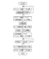
上述のようにして、起動状態となった立体撮像装置3が監視カメラ、又は認証用カメラなどとして使用され、コントローラ4のLCDパネル63には、図7に示す操作メニュー画面75が表示される。この操作メニュー画面75には、プレビュー画像及び本画像が表示される画像表示領域76、プレビュー画像開始を要求するときに押圧操作するメニューボタン77、及び本画像撮像を要求するときに押圧操作するメニューボタン78が配置されている。そして、この操作メニュー画面75のメニューボタン77に応じた位置をタッチスクリーン65で押圧操作したときに、CPU60は立体撮像装置3へプレビュー画像開始を要求する制御信号を送信する。通信I/F67、通信ケーブル5、及び通信I/F48を介して立体撮像装置3へ送信されたプレビュー画像開始要求の制御信号を受信したCPU40は、第1,2CCD23,33を含む第1,2撮像部10,11をそれぞれ起動状態として、撮像信号の出力を開始する。なお、このプレビュー画像要求の制御信号を受けたときの第1,2CCD23,33の読み出しパターンは、間欠読み出しパターンであり、この間欠読み出しパターンで1フレーム分読み出された撮像信号がシステムメモリ43に一時的に格納された後に、各種信号処理が施されてプレビュー画像データが作成され、このプレビュー画像データが通信I/F48、通信ケーブル5、及び通信I/F67を介してコントローラ4へ送信される。そして送信されたプレビュー画像データに基づいてLCDパネル63の画像表示領域76にプレビュー画像が表示される。そして以後、同様のシーケンスで次の新しいプレビュー画像が繰り返し作成されてコントローラ4へと送信され、画像表示領域76にプレビュー画像がスルー表示される。
As described above, the
上述のように、通常時はプレビュー画像データがリアルタイムでコントローラ4へと送信され、コントローラ4のLCDパネル63の画像表示領域にプレビュー画像がスルー表示される。そして、このプレビュー画像の表示中に、メニューボタン78に応じた位置をタッチスクリーン65で押圧操作されるとコントローラ4から立体撮像装置3へ本画像撮像を要求する制御信号を送信する。
As described above, the preview image data is normally transmitted to the controller 4 in real time, and the preview image is displayed through in the image display area of the
本画像撮像要求の制御信号を受信したCPU40は、CCD23,33を含む第1,2撮像部10,11の撮像モードを切り換えて各部を駆動させて本画像の撮影を行い、撮像信号を出力させる。なお、この本画像撮像要求の制御信号を受けたとき、プレビュー画像データの送信は停止状態となる。そして、この本画像撮像要求の制御信号を受けたとき第1,2撮像部10,11の撮像モードは、プレビュー撮像モードから本画像撮像モードに切り換わり、このときCCD23,33は、間欠読み出しパターンから全画素読み出しパターンに切り換わる。この全画素読み出しで1フレーム分読み出された撮像信号がシステムメモリ43に一時的に格納された後に、各種信号処理が施されて本画像データが作成され、この本画像データが通信I/F48、通信ケーブル5、及び通信I/F67を介してコントローラ4へ送信される。そして、この本画像データの送信中、CPU40は、第1,2撮像部23,33のモータドライバ22,32を駆動させて第1,2シャッタ機構18,41を閉じ状態として第1,2CCD23,33への外光の入射を遮断させる。
The
コントローラ4で受信された本画像データに基づいてLCDパネル63の画像表示領域76に本画像が表示されるととともに、コントローラ4のシステムメモリ62にこのときの本画像データが記録される。そして、本画像データの送信が終えると第1,2シャッタ機構18,41は、開放状態に戻り、第1,2撮像部23,33はプレビュー撮像モードに切り換わって撮像信号の出力を再び開始する。そして立体撮像装置3は通常時のプレビュー画像データを送信する状態に戻り、コントローラ4にプレビュー画像が表示される。
Based on the main image data received by the controller 4, the main image is displayed in the
このようにして、本画像データの送信中には、シャッタ機構18,41を閉じ状態にしてCCD23,33への外光の入射を遮断しているので、CCD23,33の劣化を防いで立体撮像装置3の使用寿命の長期化を図ることができる。特に、本実施形態では、CCD23,33が間欠読み出しパターンと、全画素読み出しパターンとを切り換えて撮像を行っているが、上述のようにして外光の入射を遮断しているので受光部の劣化を防止することが可能となっている。
In this manner, during transmission of the main image data, the
なお、上記実施形態においては、本画像撮像要求の制御信号を受けたとき、立体撮像装置3は、第1,2撮像部10,11の両方を起動して本画像を撮影して出力された撮像信号から本画像データを作成した後、コントローラ4へ本画像データを送信しており、この間プレビュー画像の送信を停止しているが、本発明はこれに限るものではない。以下では、本画像を撮影して本画像データを作成した後、本画像データを送信している間だけプレビュー画像の送信を停止し、且つこの間シャッタ機構を閉じ状態とする構成とした本発明の第2実施形態について説明する。なお、本実施形態においては、上記第1の実施形態と同様の構成の立体撮像装置3、コントローラ4、及びこれらを接続するケーブル5からなる立体撮像システムを使用する。
In the above embodiment, when the control signal for the main image capturing request is received, the
本実施形態においては、コントローラ4から立体撮像装置3へ送信する制御信号は、本画像撮像を要求する制御信号と、この本画像撮像で取得した本画像データを要求する制御信号とが設定されている。そして、本実施形態においては、これらの制御信号のうち、本画像データ要求の制御信号が受信されたときに、立体撮像装置3は、プレビュー画像データの送信を停止して、本画像データの送信を開始する。さらにこの本画像データの送信中には、シャッタ機構18,41を閉じ状態とする。
In the present embodiment, the control signal transmitted from the controller 4 to the
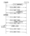
上記構成の作用について図8〜10に示すフローチャート及び図11に示す操作メニュー画面を参照して以下に説明する。なお、立体撮像装置3の取り付け、起動状態にするまでの操作などについては、上記第1実施形態と同様である。そして、コントローラ4のLCDパネル63には、図11に示す操作メニュー画面80が表示される。この操作メニュー画面80には、プレビュー画像及び本画像が表示される画像表示領域81、プレビュー画像開始を要求するときに押圧操作するメニューボタン82、本画像撮像を要求するときに押圧操作するメニューボタン83、及び撮影された本画像を要求するときに押圧操作するメニューボタン84が配置されている。そしてこの操作メニュー画面80のメニューボタン82に対応する位置のタッチスクリーン65を押圧操作して立体撮像装置3にプレビュー画像を要求する制御信号を送信する。通信I/F67、通信ケーブル5、及び通信I/F48を介して立体撮像装置3へ送信された制御信号を受信したCPU40は、第1,第2撮像部10,11を起動状態としてプレビュー撮像を行う。なお、このプレビュー撮像のときCCD23,33は、間欠読み出しパターンで1フレーム分の撮像信号を出力し、この撮像信号に各種信号処理が施されてプレビュー画像データが作成され、このプレビュー画像データが通信I/F48、通信ケーブル5、及び通信I/F67を介してコントローラ4へ送信される。そして送信されたプレビュー画像データに基づいてLCDパネル63の画像表示領域81にプレビュー画像が表示される。そして以後、同様のシーケンスで次の新しいプレビュー画像データが繰り返し作成されてコントローラ4へと送信され、LCDパネル63の画像表示領域81にプレビュー画像がスルー表示される。
The operation of the above configuration will be described below with reference to the flowcharts shown in FIGS. 8 to 10 and the operation menu screen shown in FIG. It should be noted that the operation until the
上述のように通常時は、プレビュー画像データがリアルタイムでコントローラ4へと送信され、コントローラ4の画像表示領域81にプレビュー画像がスルー表示される。そして、このプレビュー画像の表示中に、メニューボタン83に対応した位置をタッチスクリーン65で押圧操作するとコントローラ4から立体撮像装置3へ本画像撮像を要求する制御信号を送信する(図9参照)。
As described above, during normal times, preview image data is transmitted to the controller 4 in real time, and the preview image is displayed in the
本画像撮像要求の制御信号を受けたCPU40は、CCD23,33を含む第1,2撮像部10,11の各部を駆動させて本画像の撮影を行い、撮像信号を出力させる。なお、この本画像撮像要求の制御信号を受けたとき、及び本画像撮像の動作中も、プレビュー画像データの送信が続行されている。そして、この本画像撮像要求の制御信号を受けたとき第1,2撮像部10,11の撮像モードは、プレビュー撮像モードから本画像撮像モードに切り換わり、このときCCD23,33は、間欠読み出しパターンから全画素読み出しパターンに切り換わる。この全画素読み出しで1フレーム分読み出された撮像信号がシステムメモリ43に一時的に格納された後に、各種信号処理が施されて本画像データが作成される。作成された本画像データは、システムメモリ43に記憶される。
The
その後、コントローラ4で本画像データの送信を要求する操作、すなわちメニューボタン84に応じた位置のタッチスクリーン65を押圧操作されると、コントローラ4から立体撮像装置3へ本画像データ送信要求の制御信号を送信する(図11参照)。本画像データ送信要求の制御信号を受信したCPU40は、本画像データをシステムメモリ43から読み出してコントローラ4へ送信する。そして、この本画像データの送信中、CPU40は、第1,2撮像部23,33のモータドライバ22,32を駆動させて第1,2シャッタ機構18,41を閉じ状態として第1,2CCD23,33への外光の入射を遮断させる。
Thereafter, when the controller 4 performs an operation for requesting transmission of the main image data, that is, when the
コントローラ4で受信された本画像データに基づいてLCDパネル63の画像表示領域76に本画像が表示されるととともに、コントローラ4のシステムメモリ62にこのときの本画像データが記録される。そして、本画像データの送信が終えると第1,2シャッタ機構18,41は、開放状態に戻り、第1,2撮像部23,33はプレビュー撮像モードに切り換わって撮像信号の出力を再び開始する。そして立体撮像装置3は通常時のプレビュー画像データを送信する状態に戻り、コントローラ4にプレビュー画像が表示される。
Based on the main image data received by the controller 4, the main image is displayed in the
このようにして、本画像データの送信中には、シャッタ機構18,41を閉じ状態にしてCCD23,33への外光の入射を遮断しているので、CCD23,33の劣化を防いで立体撮像装置3の使用寿命の長期化を図ることができる。さらに本撮影を行っているときも同時進行でプレビュー画像データの送信を行っており、効率良くプレビュー画像の送信を行うことができる。
In this manner, during transmission of the main image data, the
なお、上記第1及び第2実施形態においては、第1,2撮像部10,11のCCD23,33の両方からプレビュー画像を取得してコントローラ4へ送信しているが、本発明はこれに限るものではない。以下で説明する本発明の第3実施形態では、2つの撮像部のうちいずれか一方を選択してプレビュー画像を取得する場合について説明する。なお、本実施形態においては、上記第1の実施形態と同様の構成の立体撮像装置3、コントローラ4、及びこれらを接続するケーブル5からなる立体撮像システムを使用する。
In the first and second embodiments, the preview images are acquired from both the
本実施形態においては、プレビュー撮像で使用する撮像部は、第1及び第2撮像部10,11のうちいずれか一方であり、これらの選択は、コントローラ4からの入力によって行われる。また、プレビュー画像を取得するときにはいずれか一方の撮像部しか使用しないが、本画像撮像を取得するときには、第1及び第2撮像部を10,11の両方をともに使用する。
In the present embodiment, the imaging unit used in the preview imaging is one of the first and
本実施形態の作用について、図12,13に示すフローチャート及び図14に示す操作メニュー画面を参照しながら説明する。なお、立体撮像装置3の取り付け、起動状態にするまでの操作などについては、上記第1実施形態と同様である。そして、コントローラ4のLCDパネル63には、図11に示す操作メニュー画面85が表示される。この操作メニュー画面85には、プレビュー画像及び本画像が表示される画像表示領域86、プレビュー画像開始を要求するときに押圧操作するメニューボタン87、プレビュー撮像に使用する撮像部を表示する表示部88a,88b、プレビュー撮像に使用する撮像部を切り換える切り換えボタン89、本画像撮像を要求するときに押圧操作するメニューボタン91、及び撮影された本画像を要求するときに押圧操作するメニューボタン92が配置されている。そしてこの操作メニュー画面85のメニューボタン87に対応する位置のタッチスクリーン65を押圧操作して立体撮像装置3にプレビュー画像を要求する制御信号を送信する。通信I/F67、通信ケーブル5、及び通信I/F48を介して立体撮像装置3へ送信された制御信号を受信したCPU40は、第1,第2撮像部10,11のうち、初期設定でプレビュー撮像を行う撮像部とされたほう、本実施形態では第1撮像部10を起動状態としてプレビュー撮像を行う。なお、このプレビュー撮像では、上記第1実施形態と同様に第1撮像部10のCCD23は間欠読み出しパターンで駆動される。また、プレビュー撮像の対象となる撮像部の初期設定は、例えばシステムメモリ43に記憶されており、立体撮像装置3の起動時にこの初期設定を読み出す。CPU40は、第1撮像部10から出力された撮像信号に各種信号処理を施して作成されたプレビュー画像データを通信I/F48、通信ケーブル5、及び通信I/F67を介してコントローラ4へ送り出す。そして送信されたプレビュー画像データに基づいてLCDパネル63の画像表示領域86にプレビュー画像が表示される。そして以後、同様のシーケンスで次の新しいプレビュー画像データが繰り返し作成されてコントローラ4へと送信され、LCDパネル63の画像表示領域86にプレビュー画像がスルー表示される。
The operation of this embodiment will be described with reference to the flowcharts shown in FIGS. 12 and 13 and the operation menu screen shown in FIG. It should be noted that the operation until the
上述のように通常時は、プレビュー画像データがリアルタイムでコントローラ4へと送信され、コントローラ4の画像表示領域86にプレビュー画像がスルー表示される。そして、このプレビュー画像の表示中に、切り換えボタン89に対応した位置をタッチスクリーン65で押圧操作すると、プレビュー撮像を行う撮像部の切り換え入力が行われる。この切り換え入力が行われると、コントローラ4から立体撮像装置3へ撮像部の切り換えを要求する制御信号を送信する。なお、このとき表示部88a,88bの表示が、第1撮像部10を示す表示部88aの点灯表示から、第2撮像部11を示す表示部88bの点灯表示に切り換わる。
As described above, in the normal time, the preview image data is transmitted to the controller 4 in real time, and the preview image is displayed through in the
撮像部切り換え要求の制御信号を受信したCPU40は、プレビュー撮像を行う撮像部を切り換える。すなわち、これまで使用していた第1撮像部10を停止状態とするとともに、第2撮像部11を起動状態としてプレビュー撮像を開始する。そして第2撮像部11から間欠読み出しで出力された撮像信号からプレビュー画像データを作成してコントローラ4へ送り出す。そして送信されたプレビュー画像データに基づいて画像表示領域86にプレビュー画像が表示される。以後、同様のシーケンスで次の新しいプレビュー画像が繰り返し作成されてコントローラ4へと送信され、モニタにプレビュー画像がスルー表示される。また、メニューボタン91に対応した位置をタッチスクリーン65で押圧操作すると本画像撮像要求の制御信号が送信され、これを受けた立体撮像装置3では、上記第1実施形態と同様に本画像データを取得する。さらにまた、メニューボタン92に対応した位置をタッチスクリーン65で押圧操作すると、本画像データ送信要求の制御信号が送信され、これを受けた立体撮像装置3では、プレビュー画像データの送信を停止して本画像データの送信を行うとともに、シャッタ機構18,41を閉じ状態にしてCCD23,33の撮像面への外光への入射を遮断する。
The
このようにしてプレビュー撮像を行っているときには、一方の撮像部のみを使用するとともに、コントローラ4からの制御信号によってプレビュー撮像を行う撮像部を切り換えることができるので、CCD23,33の劣化をさらに防止することが可能となり、立体撮像装置3の使用寿命をさらに延ばすことができる。
When preview imaging is performed in this way, only one of the imaging units is used, and the imaging unit that performs preview imaging can be switched by a control signal from the controller 4, thereby further preventing deterioration of the
なお、上記第3実施形態では、コントローラ4の操作入力を契機としてプレビュー画像を撮像する撮像部を切り換える構成としているが本発明はこれに限らず、別の動作を契機として撮像部を切り換えるようにしてもよい。以下で説明する本発明の第4実施形態では、本画像の撮影を契機として、プレビュー撮像を行う撮像部の切り換えを行う例について説明する。なお、本実施形態においては、上記第1実施形態と同様の構成の立体撮像装置3、コントローラ4、及びこれらを接続するケーブル5からなる立体撮像システムを使用する。
In the third embodiment, the imaging unit that captures the preview image is switched when the operation input from the controller 4 is triggered. However, the present invention is not limited to this, and the imaging unit is switched when triggered by another operation. May be. In the fourth embodiment of the present invention to be described below, an example will be described in which the imaging unit that performs the preview imaging is switched when the main image is captured. In the present embodiment, a stereoscopic imaging system including the
本実施形態においては、プレビュー撮像を行う撮像部は、第1及び第2撮像部10,11のうちいずれか一方であり、これらの切り換えは、本画像の撮影を契機として行われる。また、プレビュー画像を取得するときにはいずれか一方の撮像部しか使用しないが、本画像撮像を取得するときには、第1及び第2撮像部を10,11の両方をともに使用する。
In the present embodiment, the imaging unit that performs the preview imaging is one of the first and
本実施形態の作用について、図15,16に示すフローチャート及び図17に示す操作メニュー画面を参照しながら説明する。なお、立体撮像装置3の取り付け、起動状態にするまでの操作などについては、上記第1実施形態と同様である。そして、コントローラ4のLCDパネル63には、図11に示す操作メニュー画面95が表示される。この操作メニュー画面95には、プレビュー画像及び本画像が表示される画像表示領域96、プレビュー画像開始を要求するときに押圧操作するメニューボタン97、プレビュー撮像に使用する撮像部を表示する表示部98a,98b、及び本画像撮像を要求するときに押圧操作するメニューボタン99が配置されている。そしてこの操作メニュー画面95のメニューボタン97に対応する位置のタッチスクリーン65を押圧操作して立体撮像装置3にプレビュー画像を要求する制御信号を送信する。この制御信号を受信すると立体撮像装置3のCPU40は、一方の第1撮像部10を起動状態としてプレビュー撮像を行う。なお、このプレビュー撮像では、上記第1実施形態と同様に第1撮像部10のCCD23は間欠読み出しパターンで駆動される。CPU40は、第1撮像部10から出力された撮像信号に各種信号処理を施して作成されたプレビュー画像データをコントローラ4へ送り出す。そして送信されたプレビュー画像データに基づいてLCDパネル63の画像表示領域96にプレビュー画像が表示される。以後、同様のシーケンスで次の新しいプレビュー画像が繰り返し作成されてコントローラ4へと送信され、LCDパネル63の画像表示領域96にプレビュー画像がスルー表示される。
The operation of this embodiment will be described with reference to the flowcharts shown in FIGS. 15 and 16 and the operation menu screen shown in FIG. It should be noted that the operation until the
上述のように通常時は、プレビュー画像データがリアルタイムでコントローラ4へと送信され、コントローラ4の画像表示領域96にプレビュー画像がスルー表示される。そして、このプレビュー画像の表示中に、本画像撮像を示すメニューボタン99に対応した位置をタッチスクリーン65で押圧操作すると、本画像撮像を要求する制御信号がコントローラ4から立体撮像装置3に送信される。本画像撮像を要求する制御信号を受信した立体撮像装置3のCPU40は、第1,2撮像部10,11を含む各部を制御して本画像を撮像してデータを作成し、プレビュー画像データの送信を停止して本画像データを立体撮像装置3からコントローラ4へと送り出す。なお、この本画像データの送信中は、シャッタ機構18,41を閉じ状態としてCCD23,33への外光の入射を遮断する。
As described above, in normal times, preview image data is transmitted to the controller 4 in real time, and the preview image is displayed through in the
そして、本画像データの送信を開始した後、プレビュー撮像を行う撮像部を切り換える。すなわち、これまで使用していた第1撮像部10を停止状態とするとともに、第2撮像部11を起動状態としてプレビュー画像の撮像を開始する。そして、本画像データの送信が終了すると、第2撮像部11から間欠読み出しで出力された撮像信号からプレビュー画像データを作成してコントローラ4へ送り出す。そして送信されたプレビュー画像データに基づいて画像表示領域96にプレビュー画像が表示される。なお、このとき表示部98a,98bの表示が、第1撮像部10を示す表示部98aの点灯表示から、第2撮像部11を示す表示部98bの点灯表示に切り換わる。以後、同様のシーケンスで次の新しいプレビュー画像が繰り返し作成されてコントローラ4へと送信され、画像表示領域96にプレビュー画像がスルー表示される。
Then, after the transmission of the main image data is started, the imaging unit that performs the preview imaging is switched. That is, the
これ以後は、本画像データの送信が行われる毎にそれを契機として、プレビュー撮像する撮像部が、第2撮像部11から第1撮像部10に、そしてまた第2撮像部11へと順に切り換わる。このようにしてプレビュー画像の取得対象となる撮像部を切り換えることができるので、CCD23,33の劣化をさら防止することが可能となり、立体撮像装置3の使用寿命をさらに延ばすことができる。また、この場合、本画像撮像の送信を契機として切り換えを行っているので、撮像部を切り換える操作入力を行う必要がない。
Thereafter, every time transmission of the main image data is performed, the imaging unit that performs the preview imaging is switched from the
上記第3及び第4の実施形態においては、コントローラ4からの制御信号又は、本画像撮像の送信を契機としてプレビュー撮像を行う撮像部を切り換えているが、本発明はこれに限るものではなく、所定の設定時間毎に撮像部の切り換えを行うようにしてもよい。以下で説明する本発明の第5実施形態では、所定の設定時間毎に撮像部を切り換えてプレビュー画像の取得を行う例について説明する。本実施形態を適用した立体撮像装置は、図18に示す構成となっている。なお、この立体撮像装置100は、上記実施形態と同様にコントローラ(外部制御装置)4と通信ケーブル5を介して接続されている。
In the third and fourth embodiments, the imaging unit that performs the preview imaging is switched in response to the control signal from the controller 4 or the transmission of the main image imaging, but the present invention is not limited to this. You may make it switch an imaging part for every predetermined setting time. In the fifth embodiment of the present invention described below, an example in which a preview image is acquired by switching an imaging unit at predetermined time intervals will be described. A stereoscopic imaging apparatus to which this embodiment is applied has a configuration shown in FIG. The stereoscopic imaging apparatus 100 is connected to the controller (external control apparatus) 4 via the
この立体撮像装置100は、上記第1の実施形態と同様に第1および第2撮像部10,11を備えており、さらに、タイマー101と、立体撮像装置100の各部を制御するCPU102とを備えている。その他の構成として上記第1実施形態と同様の部品を用いているものについては同符号を付して説明を省略する。
The stereoscopic imaging device 100 includes first and
タイマー101は、バス42を介してCPU102に接続されており、プレビュー画像の撮像が開始されてからの経過時間を計測する。また、本実施形態においては、撮像部を切り換える設定時間がシステムメモリ43に記憶されている。
The
次に図19及び図20に示すフオーチャートを参照しながら、上記構成の作用について説明する。なお、立体撮像装置100の取り付け、起動状態にするまでの操作などについては、上記第1実施形態と同様である。また、このときのコントローラ4の操作メニュー画面は、上記第4実施形態で説明した操作メニュー画面95(図17参照)と同様である。そしてタッチスクリーン65を押圧操作して立体撮像装置3にプレビュー画像を要求する制御信号を送信する。この制御信号を受信すると立体撮像装置100のCPU102は、一方の第1撮像部10を起動状態としてプレビュー画像の撮像を行う。なお、このプレビュー画像の撮像では、上記第1実施形態と同様に第1撮像部10のCCD23は間欠読み出しパターンで駆動される。CPU102は、第1撮像部10から出力された撮像信号に各種信号処理を施して作成されたプレビュー画像データをコントローラ4へ送り出す。そして送信されたプレビュー画像データに基づいてLCDパネル63にプレビュー画像が表示される。以後、同様のシーケンスで次の新しいプレビュー画像が繰り返し作成されてコントローラ4へと送信され、LCDパネル63にプレビュー画像がスルー表示される。
Next, the operation of the above configuration will be described with reference to the flowcharts shown in FIGS. Note that the operation until the stereoscopic imaging apparatus 100 is attached and activated is the same as in the first embodiment. The operation menu screen of the controller 4 at this time is the same as the operation menu screen 95 (see FIG. 17) described in the fourth embodiment. Then, a control signal for requesting a preview image is transmitted to the
上述のように通常時は、プレビュー画像データがリアルタイムでコントローラ4へと送信され、コントローラ4にプレビュー画像がスルー表示される。そして、このプレビュー画像の送信が開始されるとき、システムメモリ43から撮像部の切り換え時間が読み出されるとともに、立体撮像装置3のタイマ101が計測を開始する。そしてタイマ101で計測する経過時間が上述の切り換え時間tに到達すると、プレビュー撮像を行う撮像部を切り換える。すなわち、これまで使用していた第1撮像部10を停止状態とするとともに、第2撮像部11を起動状態としてプレビュー撮像を開始する。そして第2撮像部11から間欠読み出しで出力された撮像信号からプレビュー画像データを作成してコントローラ4へ送り出す。そして送信されたプレビュー画像データに基づいてコントローラ4にプレビュー画像が表示される。以後、同様のシーケンスで次の新しいプレビュー画像が繰り返し作成されてコントローラ4へと送信され、LCDパネル63にプレビュー画像がスルー表示される。
As described above, during normal times, preview image data is transmitted to the controller 4 in real time, and the preview image is displayed on the controller 4 as a through display. When transmission of the preview image is started, the switching time of the imaging unit is read from the
これ以後は、所定の切り換え時間t毎に、プレビュー画像を撮像する撮像部が、第2撮像部11から第1撮像部10に、そしてまた第2撮像部11へと順に切り換わる。このようにしてプレビュー撮像を行う撮像部を切り換えることができるので、CCD23,33の劣化をさら防止することが可能となり、立体撮像装置3の使用寿命をさらに延ばすことができる。また、この場合、所定時間毎に切り換えを行っているので、撮像部を切り換える操作入力を行う必要がない。
Thereafter, at every predetermined switching time t, the imaging unit that captures the preview image is switched from the
なお、上記第1〜5実施形態においては、複数の撮像部を備えており、これらの複数の撮像部からプレビュー画像及び本画像撮像を取得する構成としているが、本発明はこれに限るものではなく、一個の撮像部だけを有する撮像装置にも適用することができる。以下で説明する本発明の第6実施形態では、撮像部が1つだけの撮像装置に適用した場合を例にあげる。本実施形態を適用した立体撮像装置は、図21に示す構成となっている。なお、この立体撮像装置100は、上記第1実施形態と同様にコントローラ(外部制御装置)4と通信ケーブル5を介して接続されている。
In the first to fifth embodiments, a plurality of imaging units are provided, and a preview image and a main image are acquired from the plurality of imaging units. However, the present invention is not limited to this. In addition, the present invention can be applied to an imaging apparatus having only one imaging unit. In the sixth embodiment of the present invention described below, a case where the present invention is applied to an imaging apparatus having only one imaging unit will be described as an example. A stereoscopic imaging apparatus to which this embodiment is applied has a configuration shown in FIG. The stereoscopic imaging apparatus 100 is connected to the controller (external control apparatus) 4 via the
この撮像装置110は、1つの撮像部115を備えており、撮像装置110の各部を制御するCPU116を備えている。その他の構成として上記第1実施形態と同様の部品を用いているものについては同符号を付して説明を省略する。
The imaging apparatus 110 includes one imaging unit 115 and includes a
このような構成の撮像装置110を監視カメラ、又は認証用のカメラなどの目的で使用するときには、撮像部115のCCD23から出力される撮像信号からプレビュー画像及び本画像撮像の取得を行ってコントローラ4へ送信する。このときのシーケンスとしては、上記第1実施形態と同様であり、撮像装置110が本画像データの送信中は、プレビュー画像データの送信を停止するとともに、シャッタ機構18を閉じ状態とする。これによってCCDの劣化を防ぎ、撮像装置110の寿命を長期化することができる。
When the imaging apparatus 110 having such a configuration is used for the purpose of a monitoring camera or an authentication camera, the controller 4 obtains a preview image and a main image from the imaging signal output from the
2 立体撮像システム
3 立体撮像装置(撮像装置)
4 コントローラ(外部制御装置)
5 通信ケーブル
10 第1撮像部
11 第2撮像部
12 筐体
13 第1撮像レンズ
15 第2撮像レンズ
18,41 シャッタ機構
23 第1CCD(撮像素子)
33 第2CCD(撮像素子)
40 102 116 CPU(制御手段)
2
4 Controller (External control device)
DESCRIPTION OF
33 Second CCD (imaging device)
40 102 116 CPU (control means)
Claims (7)
前記撮像素子から出力される撮像信号を信号処理する信号処理手段と、
外部制御装置と通信手段を介して接続され、前記外部制御装置と電気信号の送受信を行う通信処理部と、
これら各部の制御を行い、前記外部制御装置からプレビュー画像開始要求の制御信号を受けたときには、前記複数の撮像部からプレビュー画像データの取得対象となる1つのプレビュー撮像部を選択し、この選択されたプレビュー撮像部が出力した撮像信号を前記信号処理手段が信号処理してプレビュー画像データが取得されるようにするとともに、前記通信処理部が前記プレビュー画像データを前記外部制御装置にリアルタイムで送信するようにし、前記外部制御装置から本画像撮像要求の制御信号を受けたときには、前記複数の撮像部が出力した撮像信号を前記信号処理手段が信号処理して本画像データが取得されるようにするとともに、この本画像データが取得された後、前記通信処理部が前記プレビュー画像データの送信を停止して前記本画像データを前記外部制御装置に送信するようにし、前記本画像データの送信中には、前記シャッタ機構を閉じ状態として前記撮像素子への外光の入射を遮断させる制御手段と
を備えたことを特徴とする複眼撮像装置。 An optical system including a shutter mechanism , and a plurality of imaging units having an imaging element;
Signal processing means for performing signal processing on the imaging signal output from the imaging element,
A communication processing unit that is connected to the external control device via communication means, and transmits and receives electrical signals to and from the external control device ;
There line control of these units, when receiving the control signal of the preview image start request from the external control device selects one of the preview image pickup unit which to obtain the preview image data from the plurality of imaging units, the selection The signal processing means processes the image pickup signal output by the preview image pickup unit so that preview image data is obtained, and the communication processing unit transmits the preview image data to the external control device in real time. When the control signal for the main image capturing request is received from the external control device, the signal processing means processes the image capturing signals output from the plurality of image capturing units so that the main image data is acquired. as well as, after the main image data is acquired, the communication processing unit stops transmission of the preview image data Serial so as to transmit the main image data before Kigaibu controller, wherein during the transmission of the image data, and control means for shut off entrance of external light into the imaging element as a state closing the shutter mechanism
Compound-eye imaging device characterized by comprising a.
前記撮像素子から出力される撮像信号を信号処理する信号処理手段と、
外部制御装置と通信手段を介して接続され、前記外部制御装置と電気信号の送受信を行う通信処理部と、
これら各部の制御を行い、前記外部制御装置からプレビュー画像開始要求の制御信号を受けたときには、前記複数の撮像部からプレビュー画像データの取得対象となる1つのプレビュー撮像部を選択するとともに所定時間毎に別のプレビュー撮像部に切り換え、前記プレビュー撮像部が出力した撮像信号を前記信号処理手段が信号処理してプレビュー画像データが取得されるようにして、前記通信処理部が前記プレビュー画像データを前記外部制御装置にリアルタイムで送信するようにし、前記外部制御装置から本画像撮像要求の制御信号を受けたときには、前記複数の撮像部が出力した撮像信号を前記信号処理手段が信号処理して本画像データが取得されるようにするとともに、この本画像データが取得された後、前記通信処理部が前記プレビュー画像データの送信を停止して前記本画像データを前記外部制御装置に送信するようにし、前記本画像データの送信中には、前記シャッタ機構を閉じ状態として前記撮像素子への外光の入射を遮断させる制御手段と
を備えたことを特徴とする複眼撮像装置。 An optical system including a shutter mechanism, and a plurality of imaging units having an imaging element;
Signal processing means for performing signal processing on an imaging signal output from the imaging element;
A communication processing unit that is connected to the external control device via communication means, and transmits and receives electrical signals to and from the external control device ;
There line control of these units, the when the external control device receives a control signal of the preview image start request, a predetermined time with selecting one of the preview image pickup unit which to obtain the preview image data from the plurality of imaging units Each time, the communication processing unit converts the preview image data to a different preview image capturing unit so that the image processing signal output from the preview image capturing unit is processed by the signal processing means to obtain preview image data. this said to be transmitted in real time to an external control device, when receiving the control signal of the imaging request from the external control device, an image signal of the plurality of the imaging unit has outputted said signal processing means the signal processing to together so that the image data is acquired after the main image data is acquired, the communication processing unit is the flop And stops the transmission of view image data so as to transmit the main image data before Kigaibu controller, wherein during the transmission of the image data, the external light to the image sensing device as the state closing the shutter mechanism and control means for shut off the incident
Compound-eye imaging device characterized by comprising a.
前記撮像素子から出力される撮像信号を信号処理する信号処理手段と、
外部制御装置と通信手段を介して接続され、前記外部制御装置と電気信号の送受信を行う通信処理部と、
これら各部の制御を行い、前記外部制御装置からプレビュー画像開始要求の制御信号を受けたときには、前記複数の撮像部からプレビュー画像データの取得対象となる1つのプレビュー撮像部を選択し、この選択されたプレビュー撮像部が出力した撮像信号を前記信号処理手段が信号処理してプレビュー画像データが取得されるようにするとともに、前記通信処理部が前記プレビュー画像データを前記外部制御装置にリアルタイムで送信するようにし、前記外部制御装置から本画像撮像要求の制御信号を受けたときには、前記複数の撮像部が出力した撮像信号を前記信号処理手段が信号処理して本画像データが取得されるようにするとともに、この本画像データが取得された後、前記通信処理部が前記プレビュー画像データの送信を停止して前記本画像データを前記外部制御装置に送信するようにし、前記本画像データの送信中には、前記シャッタ機構を閉じ状態として前記撮像素子への外光の入射を遮断させ、前記本画像データの送信後、前記選択したプレビュー撮像部とは異なるプレビュー撮像部を前記複数の撮像部から選択する制御手段と
を備えたことを特徴とする複眼撮像装置。 An optical system including a shutter mechanism, and a plurality of imaging units having an imaging element;
Signal processing means for performing signal processing on an imaging signal output from the imaging element;
A communication processing unit that is connected to the external control device via communication means, and transmits and receives electrical signals to and from the external control device;
When these parts are controlled and a control signal for a preview image start request is received from the external control device, one preview imaging unit from which the preview image data is to be acquired is selected from the plurality of imaging units, and the selected one is selected. The signal processing unit performs signal processing on the imaging signal output by the preview imaging unit so that preview image data is acquired, and the communication processing unit transmits the preview image data to the external control device in real time. Thus, when the control signal for the main image capturing request is received from the external control device, the image processing signals output from the plurality of image capturing units are processed by the signal processing means so that the main image data is acquired. In addition, after the main image data is acquired, the communication processing unit stops transmitting the preview image data. The main image data is transmitted to the external control device, and during transmission of the main image data, the shutter mechanism is closed to block external light from entering the image sensor, and the main image data Control means for selecting, from the plurality of imaging units, a preview imaging unit different from the selected preview imaging unit after transmission;
A compound eye imaging apparatus comprising:
前記外部制御装置から送信されたプレビュー画像開始要求の制御信号を受けたとき、前記撮像部から出力された撮像信号に基づくプレビュー画像を前記外部制御装置に送信するプレビュー画像送信処理と、
前記外部制御装置から送信された本画像撮像要求の制御信号を受けたとき、前記撮像信号に基づく本画像データを作成する本画像撮像作成処理と、
この本画像撮像作成処理の後、前記プレビュー画像送信処理を停止して前記本画像データを前記外部制御装置に送信する本画像データ送信処理と、
この本画像データ送信処理が行われているとき、前記シャッタ機構を閉じ状態として前記撮像素子への外光の入射を遮断する撮像素子遮光処理と
を前記複眼撮像装置に実行させる
ことを特徴とする制御プログラム。 A control program for a compound eye imaging device having a plurality of imaging units including an optical system including a shutter mechanism and an imaging device, and connected to an external control device via a communication unit,
A preview image transmission process for transmitting a preview image based on an imaging signal output from the imaging unit to the external control device when receiving a control signal for a preview image start request transmitted from the external control device ;
When receiving a control signal of a main image capturing request transmitted from the external control device, main image capturing creation processing for creating main image data based on the imaging signal;
After the main image capturing creation processing, main image data transmission processing for stopping the preview image transmission processing and transmitting the main image data to the external control device;
When the main image data transmission process is being performed, the compound eye imaging apparatus is configured to execute an imaging element shading process for shutting off the incidence of external light to the imaging element by closing the shutter mechanism. Control program.
Priority Applications (2)
| Application Number | Priority Date | Filing Date | Title |
|---|---|---|---|
| JP2005248288A JP4402025B2 (en) | 2005-08-29 | 2005-08-29 | Compound eye imaging device and control program for compound eye imaging device |
| US11/511,304 US20070046809A1 (en) | 2005-08-29 | 2006-08-29 | Image pickup device, multi-eye image pickup device and control program for multi-eye image pickup device |
Applications Claiming Priority (1)
| Application Number | Priority Date | Filing Date | Title |
|---|---|---|---|
| JP2005248288A JP4402025B2 (en) | 2005-08-29 | 2005-08-29 | Compound eye imaging device and control program for compound eye imaging device |
Publications (3)
| Publication Number | Publication Date |
|---|---|
| JP2007067574A JP2007067574A (en) | 2007-03-15 |
| JP2007067574A5 JP2007067574A5 (en) | 2009-10-22 |
| JP4402025B2 true JP4402025B2 (en) | 2010-01-20 |
Family
ID=37803531
Family Applications (1)
| Application Number | Title | Priority Date | Filing Date |
|---|---|---|---|
| JP2005248288A Expired - Fee Related JP4402025B2 (en) | 2005-08-29 | 2005-08-29 | Compound eye imaging device and control program for compound eye imaging device |
Country Status (2)
| Country | Link |
|---|---|
| US (1) | US20070046809A1 (en) |
| JP (1) | JP4402025B2 (en) |
Families Citing this family (13)
| Publication number | Priority date | Publication date | Assignee | Title |
|---|---|---|---|---|
| JP5230376B2 (en) | 2008-11-28 | 2013-07-10 | 三星電子株式会社 | Imaging apparatus and imaging method |
| JP4759082B2 (en) * | 2009-11-18 | 2011-08-31 | 富士フイルム株式会社 | Compound eye imaging device |
| KR101723235B1 (en) * | 2010-10-04 | 2017-04-04 | 삼성전자주식회사 | Apparatus and method for attenuating three dimensional effect of stereoscopic image |
| US9204026B2 (en) * | 2010-11-01 | 2015-12-01 | Lg Electronics Inc. | Mobile terminal and method of controlling an image photographing therein |
| KR101691833B1 (en) * | 2010-11-04 | 2017-01-09 | 엘지전자 주식회사 | Mobile terminal and Method for controlling photographing image thereof |
| JP5827024B2 (en) * | 2011-03-31 | 2015-12-02 | 株式会社吉田製作所 | Control device, control method, and control program for optical coherence tomographic image generation apparatus |
| KR101843450B1 (en) * | 2011-08-23 | 2018-03-29 | 엘지전자 주식회사 | Mobile terminal and method for controlling of the same |
| US9584746B2 (en) * | 2013-06-05 | 2017-02-28 | Sony Corporation | Image processing device and imaging method for obtaining a high resolution image and efficient speed for a feedback control signal |
| JP6387700B2 (en) * | 2014-06-18 | 2018-09-12 | ソニー株式会社 | Information processing apparatus, information processing system, information processing apparatus control method, and program |
| WO2018111860A1 (en) * | 2016-12-12 | 2018-06-21 | Princeton Identity, Inc. | Systems and methods of biometric analysis |
| US11380005B2 (en) * | 2017-05-19 | 2022-07-05 | Movidius Limited | Methods, systems and apparatus to optimize pipeline execution |
| JP6864604B2 (en) * | 2017-11-02 | 2021-04-28 | 株式会社日立製作所 | Imaging device |
| US20200294209A1 (en) * | 2020-05-30 | 2020-09-17 | Intel Corporation | Camera feature removal from stereoscopic content |
Family Cites Families (6)
| Publication number | Priority date | Publication date | Assignee | Title |
|---|---|---|---|---|
| JP3361188B2 (en) * | 1994-06-16 | 2003-01-07 | 富士写真フイルム株式会社 | Electronic still camera and operation control method thereof |
| US6385772B1 (en) * | 1998-04-30 | 2002-05-07 | Texas Instruments Incorporated | Monitoring system having wireless remote viewing and control |
| GB2378078B (en) * | 2001-07-27 | 2005-05-25 | Hewlett Packard Co | Image capture |
| US20040201726A1 (en) * | 2002-03-19 | 2004-10-14 | Bloom Daniel M. | Digital camera and method for balancing color in a digital image |
| JP3987047B2 (en) * | 2004-03-05 | 2007-10-03 | ニスカ株式会社 | Imaging device and light amount adjusting device used therefor |
| US20060012685A1 (en) * | 2004-07-17 | 2006-01-19 | Hop-On Wireless, Inc. | Wireless surveillance and communications system |
-
2005
- 2005-08-29 JP JP2005248288A patent/JP4402025B2/en not_active Expired - Fee Related
-
2006
- 2006-08-29 US US11/511,304 patent/US20070046809A1/en not_active Abandoned
Also Published As
| Publication number | Publication date |
|---|---|
| US20070046809A1 (en) | 2007-03-01 |
| JP2007067574A (en) | 2007-03-15 |
Similar Documents
| Publication | Publication Date | Title |
|---|---|---|
| JP4402025B2 (en) | Compound eye imaging device and control program for compound eye imaging device | |
| JP4413258B2 (en) | Digital camera, camera body, camera system, and digital camera control method | |
| JP5171433B2 (en) | Imaging device and lens device | |
| KR20150030557A (en) | Method and Apparatus For Controlling Interchangeable Lens System Camera | |
| JP4533735B2 (en) | Stereo imaging device | |
| JP2011166756A (en) | Photographing apparatus and photographing system | |
| WO2013145907A1 (en) | Imaging device and imaging assistance method | |
| JP4437129B2 (en) | Digital camera, camera body, camera system, and digital camera control method | |
| JP4437131B2 (en) | Digital camera, camera body, camera system, and digital camera control method | |
| JP5397078B2 (en) | Imaging device | |
| JP4451353B2 (en) | Compound-eye imaging device, compound-eye imaging system, and control program for compound-eye imaging device | |
| JP4437130B2 (en) | Digital camera, camera body, camera system, and digital camera control method | |
| JP2007116271A (en) | Finder unit and digital camera and method for correcting parallax | |
| US20130076867A1 (en) | Imaging apparatus | |
| JP2018005021A (en) | Autofocus module and video camera | |
| JP2006033395A (en) | Image pickup device and stereoscopic image pickup system | |
| JP2008028997A (en) | Digital camera | |
| JP2006267374A (en) | Stereoscopic imaging apparatus, mounting method and initializing device |
Legal Events
| Date | Code | Title | Description |
|---|---|---|---|
| A711 | Notification of change in applicant |
Free format text: JAPANESE INTERMEDIATE CODE: A712 Effective date: 20070117 |
|
| A621 | Written request for application examination |
Free format text: JAPANESE INTERMEDIATE CODE: A621 Effective date: 20080206 |
|
| A521 | Request for written amendment filed |
Free format text: JAPANESE INTERMEDIATE CODE: A523 Effective date: 20090907 |
|
| A871 | Explanation of circumstances concerning accelerated examination |
Free format text: JAPANESE INTERMEDIATE CODE: A871 Effective date: 20090907 |
|
| A975 | Report on accelerated examination |
Free format text: JAPANESE INTERMEDIATE CODE: A971005 Effective date: 20091015 |
|
| TRDD | Decision of grant or rejection written | ||
| A01 | Written decision to grant a patent or to grant a registration (utility model) |
Free format text: JAPANESE INTERMEDIATE CODE: A01 Effective date: 20091021 |
|
| A01 | Written decision to grant a patent or to grant a registration (utility model) |
Free format text: JAPANESE INTERMEDIATE CODE: A01 |
|
| A61 | First payment of annual fees (during grant procedure) |
Free format text: JAPANESE INTERMEDIATE CODE: A61 Effective date: 20091028 |
|
| R150 | Certificate of patent or registration of utility model |
Free format text: JAPANESE INTERMEDIATE CODE: R150 |
|
| FPAY | Renewal fee payment (event date is renewal date of database) |
Free format text: PAYMENT UNTIL: 20121106 Year of fee payment: 3 |
|
| FPAY | Renewal fee payment (event date is renewal date of database) |
Free format text: PAYMENT UNTIL: 20121106 Year of fee payment: 3 |
|
| FPAY | Renewal fee payment (event date is renewal date of database) |
Free format text: PAYMENT UNTIL: 20131106 Year of fee payment: 4 |
|
| LAPS | Cancellation because of no payment of annual fees |