JP4394125B2 - Multi-lumen prosthesis system and method - Google Patents
Multi-lumen prosthesis system and method Download PDFInfo
- Publication number
- JP4394125B2 JP4394125B2 JP2006536617A JP2006536617A JP4394125B2 JP 4394125 B2 JP4394125 B2 JP 4394125B2 JP 2006536617 A JP2006536617 A JP 2006536617A JP 2006536617 A JP2006536617 A JP 2006536617A JP 4394125 B2 JP4394125 B2 JP 4394125B2
- Authority
- JP
- Japan
- Prior art keywords
- lumen
- trunk
- prosthetic
- assembly
- stent ring
- Prior art date
- Legal status (The legal status is an assumption and is not a legal conclusion. Google has not performed a legal analysis and makes no representation as to the accuracy of the status listed.)
- Expired - Fee Related
Links
Images


Classifications
-
- A—HUMAN NECESSITIES
- A61—MEDICAL OR VETERINARY SCIENCE; HYGIENE
- A61F—FILTERS IMPLANTABLE INTO BLOOD VESSELS; PROSTHESES; DEVICES PROVIDING PATENCY TO, OR PREVENTING COLLAPSING OF, TUBULAR STRUCTURES OF THE BODY, e.g. STENTS; ORTHOPAEDIC, NURSING OR CONTRACEPTIVE DEVICES; FOMENTATION; TREATMENT OR PROTECTION OF EYES OR EARS; BANDAGES, DRESSINGS OR ABSORBENT PADS; FIRST-AID KITS
- A61F2/00—Filters implantable into blood vessels; Prostheses, i.e. artificial substitutes or replacements for parts of the body; Appliances for connecting them with the body; Devices providing patency to, or preventing collapsing of, tubular structures of the body, e.g. stents
- A61F2/02—Prostheses implantable into the body
- A61F2/04—Hollow or tubular parts of organs, e.g. bladders, tracheae, bronchi or bile ducts
- A61F2/06—Blood vessels
- A61F2/07—Stent-grafts
-
- A—HUMAN NECESSITIES
- A61—MEDICAL OR VETERINARY SCIENCE; HYGIENE
- A61F—FILTERS IMPLANTABLE INTO BLOOD VESSELS; PROSTHESES; DEVICES PROVIDING PATENCY TO, OR PREVENTING COLLAPSING OF, TUBULAR STRUCTURES OF THE BODY, e.g. STENTS; ORTHOPAEDIC, NURSING OR CONTRACEPTIVE DEVICES; FOMENTATION; TREATMENT OR PROTECTION OF EYES OR EARS; BANDAGES, DRESSINGS OR ABSORBENT PADS; FIRST-AID KITS
- A61F2/00—Filters implantable into blood vessels; Prostheses, i.e. artificial substitutes or replacements for parts of the body; Appliances for connecting them with the body; Devices providing patency to, or preventing collapsing of, tubular structures of the body, e.g. stents
- A61F2/82—Devices providing patency to, or preventing collapsing of, tubular structures of the body, e.g. stents
- A61F2/86—Stents in a form characterised by the wire-like elements; Stents in the form characterised by a net-like or mesh-like structure
- A61F2/89—Stents in a form characterised by the wire-like elements; Stents in the form characterised by a net-like or mesh-like structure the wire-like elements comprising two or more adjacent rings flexibly connected by separate members
-
- A—HUMAN NECESSITIES
- A61—MEDICAL OR VETERINARY SCIENCE; HYGIENE
- A61F—FILTERS IMPLANTABLE INTO BLOOD VESSELS; PROSTHESES; DEVICES PROVIDING PATENCY TO, OR PREVENTING COLLAPSING OF, TUBULAR STRUCTURES OF THE BODY, e.g. STENTS; ORTHOPAEDIC, NURSING OR CONTRACEPTIVE DEVICES; FOMENTATION; TREATMENT OR PROTECTION OF EYES OR EARS; BANDAGES, DRESSINGS OR ABSORBENT PADS; FIRST-AID KITS
- A61F2/00—Filters implantable into blood vessels; Prostheses, i.e. artificial substitutes or replacements for parts of the body; Appliances for connecting them with the body; Devices providing patency to, or preventing collapsing of, tubular structures of the body, e.g. stents
- A61F2/02—Prostheses implantable into the body
- A61F2/04—Hollow or tubular parts of organs, e.g. bladders, tracheae, bronchi or bile ducts
- A61F2/06—Blood vessels
- A61F2002/065—Y-shaped blood vessels
- A61F2002/067—Y-shaped blood vessels modular
-
- A—HUMAN NECESSITIES
- A61—MEDICAL OR VETERINARY SCIENCE; HYGIENE
- A61F—FILTERS IMPLANTABLE INTO BLOOD VESSELS; PROSTHESES; DEVICES PROVIDING PATENCY TO, OR PREVENTING COLLAPSING OF, TUBULAR STRUCTURES OF THE BODY, e.g. STENTS; ORTHOPAEDIC, NURSING OR CONTRACEPTIVE DEVICES; FOMENTATION; TREATMENT OR PROTECTION OF EYES OR EARS; BANDAGES, DRESSINGS OR ABSORBENT PADS; FIRST-AID KITS
- A61F2/00—Filters implantable into blood vessels; Prostheses, i.e. artificial substitutes or replacements for parts of the body; Appliances for connecting them with the body; Devices providing patency to, or preventing collapsing of, tubular structures of the body, e.g. stents
- A61F2/02—Prostheses implantable into the body
- A61F2/04—Hollow or tubular parts of organs, e.g. bladders, tracheae, bronchi or bile ducts
- A61F2/06—Blood vessels
- A61F2/07—Stent-grafts
- A61F2002/075—Stent-grafts the stent being loosely attached to the graft material, e.g. by stitching
-
- A—HUMAN NECESSITIES
- A61—MEDICAL OR VETERINARY SCIENCE; HYGIENE
- A61F—FILTERS IMPLANTABLE INTO BLOOD VESSELS; PROSTHESES; DEVICES PROVIDING PATENCY TO, OR PREVENTING COLLAPSING OF, TUBULAR STRUCTURES OF THE BODY, e.g. STENTS; ORTHOPAEDIC, NURSING OR CONTRACEPTIVE DEVICES; FOMENTATION; TREATMENT OR PROTECTION OF EYES OR EARS; BANDAGES, DRESSINGS OR ABSORBENT PADS; FIRST-AID KITS
- A61F2220/00—Fixations or connections for prostheses classified in groups A61F2/00 - A61F2/26 or A61F2/82 or A61F9/00 or A61F11/00 or subgroups thereof
- A61F2220/0025—Connections or couplings between prosthetic parts, e.g. between modular parts; Connecting elements
- A61F2220/0075—Connections or couplings between prosthetic parts, e.g. between modular parts; Connecting elements sutured, ligatured or stitched, retained or tied with a rope, string, thread, wire or cable
Abstract
Description
(発明の分野)
本発明は、一般に補綴具に関し、そして、特に、中空の身体器官および/または血管の疾患セクションおよび/または損傷したセクションの修復で用いられる補綴具に関する。
(Field of Invention)
The present invention relates generally to prosthetic devices and, more particularly, to prosthetic devices used in the repair of diseased and / or damaged sections of hollow body organs and / or blood vessels.
(発明の背景)
損傷または疾患からの血管の弱体化は、血管拡張および動脈瘤の形成に至り得る。処置しないでおくと、動脈瘤は、サイズが大きくなり、そして最終的には破裂し得る。
(Background of the Invention)
Vascular weakening from injury or disease can lead to vasodilation and aneurysm formation. If left untreated, the aneurysm can grow in size and eventually rupture.
例えば、大動脈の動脈瘤は、主に腹部領域、通常、腎動脈と大動脈分岐との間の腎臓下の領域で生ずる。動脈瘤はまた、大動脈弓と腎動脈との間の胸部領域で生じ得る。大動脈瘤の破裂は、大量の出血を生じ、そして高い割合の死亡率を有している。 For example, an aortic aneurysm occurs primarily in the abdominal region, usually in the subrenal region between the renal arteries and the aortic bifurcation. An aneurysm can also occur in the thoracic region between the aortic arch and the renal artery. Aortic aneurysm rupture results in massive bleeding and has a high rate of mortality.
血管の疾患セクションまたは損傷セクションの開放手術置換(open surgical replacement)は、血管破裂のリスクをなくし得る。この手順では、血管の疾患セクションまたは損傷セクションは取り除かれ、そして真直ぐ、または分岐した形態のいずれかで作製された補綴具移植片が導入され、そして、次に、縫合糸により生来の血管の端部に永久的に付着され、かつシールされる。これら手順のための補綴具移植片は、通常、支持されない織られたチューブであり、そして代表的には、ポリエステル、ePTFEまたはその他の適切な材料から作製される。これら移植片は、長軸方向には支持されていないので、それらは、動脈瘤および生来の血管の形態における変化に適応し得る。しかし、これらの手順は、大きな外科的切開を必要とし、そして高い割合の罹患率および死亡率を有している。さらに、多くの患者は、その他の同時にある病的状態に起因して、このタイプの主要な手術には不適切である。 Open surgical replacement of diseased or damaged sections of blood vessels can eliminate the risk of vascular rupture. In this procedure, the diseased or damaged section of the blood vessel is removed and a prosthetic graft made either in a straight or branched form is introduced, and then the end of the native blood vessel is sutured Permanently attached to the part and sealed. Prosthetic implants for these procedures are usually unsupported woven tubes and are typically made from polyester, ePTFE or other suitable material. Since these implants are not longitudinally supported, they can accommodate changes in the morphology of aneurysms and native blood vessels. However, these procedures require large surgical incisions and have a high rate of morbidity and mortality. Furthermore, many patients are unsuitable for this type of major surgery due to other concurrent morbidity.
血管内動脈瘤修復は、開放外科的修復にともなう問題を克服するために導入されている。動脈瘤は、管腔内に配置される血管補綴具で架橋される。代表的には、大動脈の動脈瘤のためのこれらの補綴具移植片は、大腿動脈を通じてカテーテル上を折り畳まれて送達される。これらの移植片は、通常、金属製の足場となる(ステント)構造に取り付けられた繊維材料とともに設計されており、これは、拡大するか、または拡大されて血管の内径に接触する。開放外科的動脈瘤修復とは異なり、管腔内に展開された移植片は、生来の血管には縫合されず、展開の間に生来の血管中に貫通するステントから延びるとげ(barb)に依存するか、またはステントそれ自体の半径方向の拡大力が利用されるかのいずれかで、この移植片をその場に保持する。これらの移植片取り付け手段は、縫合糸と比較したとき同じレベルの取り付けを提供せず、そして展開に際し、生来の血管を損傷し得る。 Intravascular aneurysm repair has been introduced to overcome the problems associated with open surgical repair. The aneurysm is bridged with a vascular prosthesis placed within the lumen. Typically, these prosthetic implants for aortic aneurysms are delivered folded over a catheter through the femoral artery. These implants are usually designed with a fibrous material attached to a metal scaffolding (stent) structure that expands or expands into contact with the inner diameter of the blood vessel. Unlike open surgical aneurysm repair, a graft deployed in the lumen is not sutured to the native blood vessel and relies on a barb that extends from the stent that penetrates into the native blood vessel during deployment. Or the radial expansion force of the stent itself is utilized to hold the implant in place. These graft attachment means do not provide the same level of attachment when compared to sutures and can damage native blood vessels upon deployment.
(発明の要旨)
本発明は、中空の身体器官および/または血管の疾患セクションおよび/または損傷セクションを修復するための装置および方法を提供する。
(Summary of the Invention)
The present invention provides devices and methods for repairing diseased and / or damaged sections of hollow body organs and / or blood vessels.
本発明の1つの局面は、血管または中空の身体器官のための補綴具を提供する。この補綴具は、内部を有するトランクを備える。この内部にある内部隔壁は、このトランク内部の少なくとも一部分内に、多管腔流れチャネル形態を規定するサイズおよび形態である。1つの実施形態では、この多管腔流れチャネル形態は、第1の内部管腔および第2の内部管腔を含む。これら内部管腔の少なくとも1つは、管腔拡大部構成要素を受容するようなサイズおよび形態であり、拡大された管腔を規定する。 One aspect of the present invention provides a prosthesis for a blood vessel or hollow body organ. The prosthesis includes a trunk having an interior. The internal septum within is sized and configured to define a multi-lumen flow channel configuration within at least a portion of the interior of the trunk. In one embodiment, the multi-lumen flow channel configuration includes a first internal lumen and a second internal lumen. At least one of these internal lumens is sized and configured to receive a lumen enlargement component and defines an enlarged lumen.
本発明の別の局面は、補綴具を展開するための方法を提供する。この方法は、上記に記載のように、補綴具を、血管または中空の身体器官を含む標的部位中に導入する。この方法は、上記補綴具のトランクを、標的部位において身体組織と接触して配置する。この方法はまた、上記管腔拡大部分を上記トランクに適合し得る。1つの実施形態では、この方法は、上記トランクを、標的部位にある身体組織に固定する。 Another aspect of the present invention provides a method for deploying a prosthesis. This method introduces a prosthetic device into a target site, including a blood vessel or hollow body organ, as described above. This method places the prosthesis trunk in contact with body tissue at a target site. This method may also adapt the lumen expansion to the trunk. In one embodiment, the method secures the trunk to body tissue at the target site.
本発明のその他の特徴および利点は、添付の説明、図面および請求項に基づき明らかである。 Other features and advantages of the invention will be apparent based on the accompanying description, drawings, and claims.
本発明は、添付の図面を合わせて考慮し、以下の好ましい実施形態の詳細な説明から理解され得る。 The present invention may be understood from the following detailed description of the preferred embodiments, considered in conjunction with the accompanying drawings.
(発明の詳細な説明)
(I.多管腔補綴具アセンブリ)
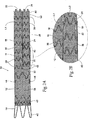
図1は、本発明の特徴を具現化する多管腔補綴具アセンブリ10を示す。示される実施形態において、この多管腔補綴具アセンブリ10は、トランク構成要素12および少なくとも1つの拡大部構成要素26を備える。
(Detailed description of the invention)
(I. Multi-lumen prosthesis assembly)
FIG. 1 illustrates a
このトランク構成要素12は、中空の身体器官および/または血管内に適合するサイズおよび形態である。本明細書に記載されるように、展開の標的部位は、後に、より詳細に説明さるように、腎動脈に隣接する大動脈内にある。しかし、展開のこの標的部位は、このアセンブリ10の特徴を示す目的のために選択され、そして制限的であることは意図されない。
The
このトランク構成要素12は、上記補綴具中またはそれからの流体流れのための近位開口部14と連通する内部を含む。このトランク構成要素12は、その内部内に隔壁16を含む。この補綴具内の隔壁16の長さは変動し得る。示される実施形態では、この隔壁16は、このトランク構成要素12の全体長さに沿っては伸びず、上記近位開口部14から距離を置かれている。示される配列では、この隔壁16は長軸方向の縫い目を備える。この縫い目は、例えば、このトランク構成要素12の材料36(これは代表的には織物である)の対向する面(すなわち、前および後)を一緒に、縫うこと、熱結合すること、または織ることにより形成され得、それによって、2つの管腔18と20との間に隔壁または共有される共通の壁を形成する(図7Aおよび7Bを参照のこと)。
The
この隔壁16は、トランク構成要素12の内部の少なくとも一部分を多管腔流れチャネネル形態に変形する。示される実施形態では、この多管腔流れチャネル形態は、2つの第1および第2の内部管腔18および20を備える。この隔壁16に起因して、多管腔流れチャネル形態の2つの第1および第2の内部管腔18および20は、(図7Aおよび7Bが示すように)分枝または分枝脚を形成しない。共有する共通の壁(隔壁16)は分岐を防ぎ、そして管腔18および20を、(図7Aおよび7Bが示すように)分岐しないほぼ平行な流れ関係に維持する。
This
示される配列では、この隔壁16は、トランク構成要素12の中央線にほぼ沿って走り、本質的に対称なこのトランク構成要素12内の多管腔流れチャネル形態を作る。しかし、この隔壁16が、非対称の多管腔流れチャネル形態を形成し得ることを、認識すべきである。複数の隔壁がこの内部内に存在し得、このトランク構成要素12の内部をいくつかの流れ管腔に変形することもまた認識されるべきである。この隔壁の長さは変動し得る。代表的な実施形態では、この隔壁は、代表的には、長さが10mmより長く、そして長さが5mmよりは短くない。
In the arrangement shown, the
示される実施形態では、第2の管腔20は、上記隔壁16の少なくとも一部分に沿って短縮されている。結果として、上記第1の管腔18の遠位開口部22は、この第2の管腔20の遠位開口部24を超えて伸びるということができる。なお、この共有された共通の壁(隔壁16)は分岐を防ぎ、そしてこれら管腔18および20を非分岐のほぼ平行な流れ関係に維持する。
In the embodiment shown, the
上記第1の管腔18は、近位開口部14から規定された間隔を置かれた標的目標または供給源に到達するようなサイズおよび形態の流れチャネルを規定し、その一方、上記短縮された第2の管腔20は、このトランク構成要素12自体の近位開口部14として、ほぼ同じ標的目標と連通する。さらに隔壁16は、流れチャネル拡大部の短縮された第2の管腔20への連結に適応するようなサイズおよび形態であり、所望であれば、同様に、別の標的供給源または遠位開口部24から間隔を置かれた目標へのその到達度を拡大する。
The
この配列では(図2Aを参照のこと)、この多管腔補綴具アセンブリ10は、流れチャネル拡大部構成要素を含む。この拡大部構成要素26は、上記トランク構成要素12の短縮された第2の管腔20内に入れ子式に適合されるサイズおよび形態である近位端32を含む。この拡大部構成要素26の遠位端34は、この短縮された第2の管腔20の到達度を、上記近位開口部14から規定された距離だけ間隔を置かれた別の標的目標または供給源まで拡大するサイズおよび形態である。結果として、拡大された第2の管腔20の一部分は、隔壁16によって第1の管腔18に接続され、そしてこの拡大された第2の管腔20の一部分は、隔壁16によって第1の管腔18に接続されない。
In this arrangement (see FIG. 2A), the
上記隔壁16によって第1の管腔18に接続されている上記トランク構成要素12の短縮された第2の管腔20は、第2の管腔18のように、このトランク構成要素12自体の本体内に完全に包まれる界面領域またはソケットを提供する。この短縮された第2の管腔20は、従って、ねじれるか、もしくはよじれるか、またはトランク構成要素12とは独立のその他の種類の運動の傾向はない。この第2の管腔20を通るガイドワイヤの通過は、妨げられないで起こり得る。
The shortened
この界面領域またはソケット内に入れ子式に適合され、かつトランク構成要素12内に囲まれて、拡大部構成要素26の機械的性質は、トランク構成要素12自体の構造的支持および一体性によって補充され、そして逆もまた真実である。一緒に連結されて、トランク構成要素12および拡大部構成要素26は、トランク構成要素12からの拡大部構成要素26の移動および/または分離に対する増大された抵抗性を提供する。この囲まれた界面領域内に収まって、拡張部構成要素26は、トランク構成要素12内で周縁がシールされ、拡大部構成要素26の周りの流体の漏れまたは漏出に抵抗する。隔壁16はテーパー状、湾曲、波状、またはその他の非直線状であり得、この拡大部構成要素とトランク構成要素12との間の連結を増大する。
Nested within this interface region or socket and enclosed within the
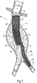
1つの示される使用では(図3を参照のこと)、トランク構成要素12は、第1および第2の腸骨動脈の分岐の領域中の大動脈中に展開され得る。適正に展開されるとき、第1の管腔18は、この分岐の第1の腸骨動脈中に到達するサイズであり得、その一方、第2の管腔20は、大動脈との連通を維持する。このトランク構成要素12が展開された後(図4を参照のこと)、拡大部構成要素26は、第2の管腔20の開口部24内に適合され得、その結果、第2の管腔20の遠位端34は、上記分岐の第2の腸骨動脈中に到達し得る。この配列では、第1の管腔18は、補綴具の第1の脚L1として供され、そして拡大部構成要素26は、対側脚L2として供される。
In one shown use (see FIG. 3), the
記載されるように、トランク構成要素12および拡大部構成要素26の両者は、所望であれば、個々の自己拡張性のジグザグタイプのステントリング38を保持する補綴具材料36を利用する。このステントリング38は、補綴具全体で互いに取り付けられる必要はない。しかし、この補綴具構造内の特定位置で個々のステントリング38間に取り付け具を有し、安定性および/またはさらなる半径方向支持を提供することが所望され得る。先に述べたように、隔壁16は、トランク構成要素12の補綴具材料36の対向する面(すなわち、前および後)を一緒に、縫うか、熱結合するか、または織ることにより形成される。隔壁16の領域において、ステントリング38は、形成された管腔の周りを隔壁16から伸びるが、隔壁16自体には侵入しないか、またはそうでなければ中断しない。この隔壁16は連続的であり、そしてステントリング38の支持構造から別個に形成される。
As described, both the
個々のステントリング38は、補綴具管腔の半径方向支持を維持しながら、長軸方向の補綴具コンプライアンスを許容する。この技術的特徴は、この補綴具が、血管/動脈瘤形態における変化により容易に適応することを可能にする。 The individual stent rings 38 allow longitudinal prosthetic compliance while maintaining radial support of the prosthetic lumen. This technical feature allows the prosthesis to be more easily adapted to changes in vessel / aneurysm morphology.
このステントリング38は、例えば、Nitinol(登録商標)ワイヤから作製され得る。なお、その他の材料、製造方法および設計が用いられ得る。ステントリング38の各々は、補綴具材料36上に縫いつけられる。特定の場所では、補綴具材料36の外径に取り付けられたステントリング38を有することが所望される。なお、このステントリング38は、上記ステント材料36の内径に取り付けられ得ることもまた企図される。
The
示される実施形態では、この補綴具材料36は織られたポリエステルであり、そしてこのステントリング38の取り付けはポリエステル縫合糸でなされる。しかし、その他の取り付け手段を利用してこのステントリング38を補綴具材料36に固定し得ることもまた企図される。これらの手段は、結合形成;このステントリング38を補綴具材料36の2つの層の間に捕捉すること;およびこのステントリング38を織られた補綴具材料36中に直接取り込むことを含む。
In the embodiment shown, the
トランク構成要素12は、補綴具材料36を超えて延びる腎臓上ステント40をその近位端に含み得る。大動脈内に展開されるとき、このステントは、腎動脈のレベルを超えて伸び得る。この腎臓上ステントは、補綴具を管腔内に向け、そして、腎動脈中への正常な血流を妨害することなく、この大動脈中の補綴具の位置を維持することを支援する。
The
トランク構成要素12において、(腎臓上ステント40の遠位方向にある)この補綴具の近位端は、代表的には、1つ以上のステントリング38を有する。このステントリング38の目的は、血管壁とこの移植片との間に、血液がこの補綴具の外側を流れないようにシールを提供すること、そして大動脈中の補綴具の位置を維持することを支援することである。代表的には、大動脈のこの領域(腎動脈の真下の動脈瘤の近位方向頸部)はまた、1つ以上の固定具が、望ましくは、この補綴具をその場に係留するために固定具取り付けアセンブリよって導入される場所である。この固定具取り付けアセンブリのさらなる詳細は、2002年11月29日に出願され、本明細書中に参考として援用される米国特許出願第10/307,226号中に見い出され得る。トランク構成要素12のこの領域は、固定具の受領および保持のためのサイズおよび形態、例えば、これら固定具の配置に特に適応するためのサイズおよび間隔のリングステントパターン;および/またはこれら固定具の配置に特に適応するための「X−パターン」または「正弦パターン」を有する織られた繊維の使用;および/または上記補綴具材料の上に折り畳まれて複数の層を形成し、固定具が配置される領域でこの補綴具を補強すること;および/またはより密な織りパターン、または例えば、Kevlar(登録商標)材料またはVectran(登録商標)材料からのより強い繊維の使用、または固定具が配置される領域中で単独に織られたか、もしくは代表的なポリエステル繊維で編み合わされた金属ワイヤであることが所望される。上記固定ステープルを位置決めを支援するために、上記補綴具材料36またはステントリング38の上の放射線不透過性マーカー42によって補綴具のこの領域を蛍光透視法で示すこともまた所望され得る。
In the
さらなるステントリング38が第1の構成要素12の本体トランク全体で利用され得る。望ましくは、最小の数のステントリング38がこのトランク構成要素12内で利用され得る。代表的には、しかし、ステントリング38は、上記本体トランク中で長軸方向の縫い目16のすぐ近位方向に取り付けられ得る。
Additional stent rings 38 may be utilized throughout the body trunk of the
本体トランク中の長軸方向の縫い目16は、上記補綴具材料36の前と後とを一緒に裁縫、熱結合、またはおそらくは織ることによるような方法によって生成され得る。代表的には、この縫い目16は、上記本体トランクの中央線に沿って位置され得、2つの等しいサイズの管腔18および20を生成する。しかし、この縫い目16の位置は、異なるサイズの管腔が所望されるのなら移動され得る。
トランク構成要素12中の複数の管腔18および20は、代表的には、補綴具材料36の内側上のステントリング38で支持され得る。理想的には、1つの管腔18中のステントリング38は、他方の管腔20にあるステントリング38と千鳥状の位置にあり、その結果、それらは、第1の構成要素12が展開の前に半径方向に圧縮されるとき、互いに重複しない。代表的には、ステントリング38は、トランク構成要素12の第1の管腔18の外側に取り付けられ得る。
The plurality of
血管管腔または中空の身体器官内のトランク構成要素12の回転配向は、蛍光透視法下で見るために上記補綴具に取り付けられたさらなる放射線不透過性マーカー44で達成される。代表的には、これらのマーカー44は、補綴具材料36に取り付けられ得る。なお、これらマーカー44は、補綴具材料に代わって、またはそれに加えステントリング38に取り付けられ得る。これら放射線不透過性マーカー44は、代表的には、白金、白金/イリジウム、または金のような放射線不透過性材料から作製されたマーカーバンド、きつく巻かれたコイル、またはワイヤの形態である。これらの放射線不透過性マーカー44は、補綴具材料36またはステントリング38に取り付けられ得、すべての補綴具開口部の位置を蛍光透視法で決定することを支援し、そしてトランク構成要素12の第2の管腔20中への拡大部構成要素26についての挿入深さを示す。望ましくは、一方が他方より長い2つのマーカー44が、第1の構成要素12の本体トランクの対向する側面上に、より長いマーカーを脚L1の側面上に整列して取り付けられる。これら2つのマーカー44は、使用者が、送達システム中の上記補綴具の適正な回転配向を決定することを可能にし、その結果、展開の際に、第2の遠位開口部20が対側の腸骨動脈と整列される。
Rotational orientation of the
拡大部構成要素26は、その全体長さに沿って、補綴具材料36の外側に取り付けられたステントリング38を、これらのストントリング38間の特定の間隔を備えて有している。しかし、上記トランク構成要素12におけるように、これらステントリング38はまた、補綴具材料36の内側上に配置され得ることが企図される。さらに、先に論議されたように、これらステントリング38は、補綴具全体で互いに取り付けられる必要はない。しかし、補綴具構造内の特定の位置で個々のステントリング38間に取り付け物を有することが所望され得、安定性および/またはさらなる半径方向支持を提供する。拡大部構成要素26へのステントリング38の付加は、この拡大部構成要素26の展開を支援し、そしてこの拡大部構成要素26内の管腔の半径方向支持を維持しながら、長軸方向のコンプライアンスを許容する。代表的には、放射線不透過性マーカー42を上記補綴具の各端部上で用いて、第1の構成要素12の第2の遠位開口部24の管腔内で拡大部構成要素26の配置を可視化する際に支援する。
The
図2Aおよび2Bに示されるように、拡大部構成要素26中のステントリング38は、本体トランク12の第2の管腔20中のステントリング38を係合するようなサイズであり、形態であり、そしてそのように配列され得る。この係合は、拡大部構成要素26が、この拡大部構成要素26が展開された後、第2の管腔20との関係で長軸方向に動くか、または移動することを防ぐ。
As shown in FIGS. 2A and 2B, the
(II.多管腔補綴具アセンブリの使用)
使用の間に(図5を参照のこと)、第1のカテーテル46は、腸骨動脈を通り、腎動脈近傍の大動脈内の所望の位置までガイドワイヤ48上で操縦される。このカテーテル46は、多管腔補綴具システム10のトランク構成要素12を半径方向に減少した形態で運ぶ。標的部位において、このカテーテル46は、トランク構成要素12を放出し、これは、図3に示される位置に半径方向に拡大する。
(II. Use of multi-lumen prosthesis assemblies)
During use (see FIG. 5), the
図6が示すように、拡大部構成要素26は、対側の腸骨動脈から入来する別のガイドワイヤ上カテーテル50によって、半径方向に圧縮された状態で運ばれる。このカテーテル50は、拡大部構成要素26を、この拡大部構成要素26の近位端がトランク構成要素12の第2の管腔内に入れ子式に受容され、そして遠位端が、図4が示すように対側の腸骨動脈中に伸びるように展開する。この拡大部構成要素26がトランク構成要素12の第2の管腔20内に入れ子式に受容されるときにのみ、分岐補綴具が分岐脚とともに形成される。
As FIG. 6 shows, the
本発明の好ましい実施形態が、説明および明瞭さのための完全な開示を提示する目的で詳細に上記に記載される。当業者は、本開示の範囲および思想内でその他の改変を想定し得る。 Preferred embodiments of the present invention are described above in detail for the purpose of providing a complete disclosure for explanation and clarity. Those skilled in the art will envision other modifications within the scope and spirit of the present disclosure.
本発明の上記に記載の実施形態は、その原理の単なる記述であり、そして制限されるものではない。それに代わって、本発明の範囲は、それらの等価物を含んで、以下の請求項の範囲から決定される。 The above-described embodiments of the invention are merely descriptions of the principles and are not limiting. Instead, the scope of the invention shall be determined from the scope of the following claims, including their equivalents.
Claims (15)
織物補綴具材料を含むトランクであって、該織物補綴具材料が該トランク中への、または該トランクからの流体流れのための近位開口部と連通する内部を規定し、該トランクが、
該近位開口部から距離を置かれ、そして織物補綴具材料の対向する表面をともに接続し、該トランクの内部内に少なくと第1の内部管腔および該第1の管腔より短い短縮された第2の内部管腔を備える多管腔流れチャネル形態を規定するようなサイズおよび形態である内部隔壁を形成する縫い目と、
該近位開口部の周りで該織物補綴具材料に連結される第1の環状ステントリング構造物と、
該第1の環状ステントリング構造物から離れて間隔を置かれ、そして該第1の環状ステントリング構造物に互いに取り付けられず、そして該隔壁に侵入または該隔壁を中断することなく該第1の内部管腔の周りで該織物補綴具材料に連結される第2の環状ステントリング構造物と、
該第1の環状ステントリング構造物および該第2の環状ステントリング構造物から離れて間隔を置かれ、そして該1の環状ステントリング構造物および該第2の環状ステントリング構造物に互いに取り付けられず、そして該隔壁に侵入または該隔壁を中断することなく該短縮された第2の内部管腔の周りで該織物補綴具材料に連結される第3の環状ステントリング構造物とを含み、
該間隔を置かれて離れ、そして互いに取り付けられない第1、第2、および第3の環状リング構造物が該トランクの半径方向の支持を維持しながら該トランクの長軸方向のコンプライアンスを可能にし、該第1の環状ステントリング構造物が、該第2の環状ステントリング構造物および第3の環状ステントリング構造物とは異なるサイズおよび形態であり、該補綴具をその場に係留して収容するトランク、および
該第1の内部管腔および該第2の内部管腔の少なくとも1つ内に適合されるようなサイズおよび形態であり、該少なくとも1つの内部管腔の拡大部を規定する拡大部構成要素を備える、補綴具アセンブリ。A complement binding device assembly for a blood vessel or hollow body organ,
A trunk comprising a woven product prosthetic material, said textile prosthetic material into the trunk, or defining an interior communicating with a proximal opening for fluid flow from said trunk, said trunk ,
Put the distance from the proximal opening, the opposed surfaces of the woven product prosthetic materials Te elements are connected together, shorter than the least the first inner lumen and the first lumen into the interior of the trunk Seams forming an internal septum that is sized and configured to define a multi-lumen flow channel configuration with a shortened second internal lumen;
A first annular stent ring structure coupled to the textile prosthetic material about the proximal opening;
Spaced apart from the first annular stent ring structure and not attached to the first annular stent ring structure and the first annular stent ring structure without entering or interrupting the septum A second annular stent ring structure coupled to the textile prosthetic material about an inner lumen;
Spaced apart from the first annular stent ring structure and the second annular stent ring structure and attached to the first annular stent ring structure and the second annular stent ring structure And a third annular stent ring structure coupled to the textile prosthetic material around the shortened second inner lumen without entering or interrupting the septum ,
First, second, and third annular ring structures that are spaced apart and not attached to each other allow longitudinal compliance of the trunk while maintaining radial support of the trunk. The first annular stent ring structure is of a different size and form than the second annular stent ring structure and the third annular stent ring structure , and the prosthetic device is anchored in place and received trunks, and a size and form as adapted within at least one of the first inner lumen and said second inner lumen, you define an enlarged portion of one inner lumen said at least comprising the expansion voluminous components, the prosthesis assembly.
請求項1に規定される補綴具アセンブリを、血管または中空の身体器官を含む標的部位中に導入する手段、および
該補綴具を該標的部位において身体組織と接触して位置決めする手段、を備える、システム。A system for deploying a prosthesis,
Comprising an auxiliary binding device assembly that will be defined in Claim 1, means for introducing into the target site comprising a blood vessel or hollow body organ, and means for positioning in contact with body tissue at the target site the prosthesis, the ,system.
請求項1に規定される補綴具アセンブリを、血管または中空の身体器官を含む標的部位中に導入する手段、
該補綴具アセンブリのトランクを該標的部位において身体組織と接触して位置決めする手段、および
該補綴具アセンブリの管腔拡大部を該トランクに適合する手段、を備える、システム。A system for deploying a prosthesis,
Complement binding device assembly that will be defined in Claim 1, means for introducing into the target site comprising a blood vessel or hollow body organ,
Means for positioning the prosthesis assembly trunk in contact with body tissue at the target site, and means for fitting a lumen enlargement of the prosthesis assembly to the trunk.
Applications Claiming Priority (2)
| Application Number | Priority Date | Filing Date | Title |
|---|---|---|---|
| US10/693,255 US6929661B2 (en) | 2001-11-28 | 2003-10-24 | Multi-lumen prosthesis systems and methods |
| PCT/US2004/027590 WO2005044148A1 (en) | 2003-10-24 | 2004-08-25 | Multi-lumen prosthesis systems and methods |
Related Child Applications (1)
| Application Number | Title | Priority Date | Filing Date |
|---|---|---|---|
| JP2008306790A Division JP2009106763A (en) | 2003-10-24 | 2008-12-01 | Multi-lumen prosthesis implement system and method |
Publications (3)
| Publication Number | Publication Date |
|---|---|
| JP2007508895A JP2007508895A (en) | 2007-04-12 |
| JP2007508895A5 JP2007508895A5 (en) | 2007-10-18 |
| JP4394125B2 true JP4394125B2 (en) | 2010-01-06 |
Family
ID=34573197
Family Applications (2)
| Application Number | Title | Priority Date | Filing Date |
|---|---|---|---|
| JP2006536617A Expired - Fee Related JP4394125B2 (en) | 2003-10-24 | 2004-08-25 | Multi-lumen prosthesis system and method |
| JP2008306790A Pending JP2009106763A (en) | 2003-10-24 | 2008-12-01 | Multi-lumen prosthesis implement system and method |
Family Applications After (1)
| Application Number | Title | Priority Date | Filing Date |
|---|---|---|---|
| JP2008306790A Pending JP2009106763A (en) | 2003-10-24 | 2008-12-01 | Multi-lumen prosthesis implement system and method |
Country Status (11)
| Country | Link |
|---|---|
| US (2) | US6929661B2 (en) |
| EP (2) | EP2119416B1 (en) |
| JP (2) | JP4394125B2 (en) |
| CN (1) | CN1870951B (en) |
| AT (2) | ATE546109T1 (en) |
| AU (1) | AU2004287355B2 (en) |
| CA (1) | CA2546721C (en) |
| DE (1) | DE602004022444D1 (en) |
| DK (1) | DK1680045T3 (en) |
| ES (2) | ES2356353T3 (en) |
| WO (1) | WO2005044148A1 (en) |
Families Citing this family (95)
| Publication number | Priority date | Publication date | Assignee | Title |
|---|---|---|---|---|
| US7491232B2 (en) | 1998-09-18 | 2009-02-17 | Aptus Endosystems, Inc. | Catheter-based fastener implantation apparatus and methods with implantation force resolution |
| US8034100B2 (en) | 1999-03-11 | 2011-10-11 | Endologix, Inc. | Graft deployment system |
| US6261316B1 (en) | 1999-03-11 | 2001-07-17 | Endologix, Inc. | Single puncture bifurcation graft deployment system |
| CA2464287C (en) | 2001-10-23 | 2011-02-08 | Tyco Healthcare Group Lp | Surgical fasteners |
| US8231639B2 (en) | 2001-11-28 | 2012-07-31 | Aptus Endosystems, Inc. | Systems and methods for attaching a prosthesis within a body lumen or hollow organ |
| US7828838B2 (en) * | 2001-11-28 | 2010-11-09 | Aptus Endosystems, Inc. | Devices, systems, and methods for prosthesis delivery and implantation, including a prosthesis assembly |
| US20090112302A1 (en) * | 2001-11-28 | 2009-04-30 | Josh Stafford | Devices, systems, and methods for endovascular staple and/or prosthesis delivery and implantation |
| US9320503B2 (en) | 2001-11-28 | 2016-04-26 | Medtronic Vascular, Inc. | Devices, system, and methods for guiding an operative tool into an interior body region |
| US20050177180A1 (en) | 2001-11-28 | 2005-08-11 | Aptus Endosystems, Inc. | Devices, systems, and methods for supporting tissue and/or structures within a hollow body organ |
| JP4405262B2 (en) | 2001-11-28 | 2010-01-27 | アプタス エンドシステムズ, インコーポレイテッド | Intravascular aneurysm repair system |
| US20070073389A1 (en) | 2001-11-28 | 2007-03-29 | Aptus Endosystems, Inc. | Endovascular aneurysm devices, systems, and methods |
| US7147661B2 (en) | 2001-12-20 | 2006-12-12 | Boston Scientific Santa Rosa Corp. | Radially expandable stent |
| JP4319980B2 (en) | 2002-06-11 | 2009-08-26 | タイコ ヘルスケア グループ エルピー | Hernia mesh tack |
| US11890181B2 (en) * | 2002-07-22 | 2024-02-06 | Tmt Systems, Inc. | Percutaneous endovascular apparatus for repair of aneurysms and arterial blockages |
| EP1635723B1 (en) | 2003-06-13 | 2011-08-10 | Tyco Healthcare Group LP | Multiple member interconnect for surgical instrument and absorbable screw fastener |
| US8926637B2 (en) | 2003-06-13 | 2015-01-06 | Covidien Lp | Multiple member interconnect for surgical instrument and absorbable screw fastener |
| US10478179B2 (en) | 2004-04-27 | 2019-11-19 | Covidien Lp | Absorbable fastener for hernia mesh fixation |
| EP1621161B1 (en) * | 2004-07-28 | 2009-11-18 | Cordis Corporation | Device having connected bifurcated legs to treat abdominal aortic aneurysm |
| EP1621158A1 (en) * | 2004-07-28 | 2006-02-01 | Cordis Corporation | Reduced profile abdominal aortic aneurysm device |
| EP1773249B1 (en) * | 2004-07-28 | 2009-12-09 | Cordis Corporation | Abdominal aortic aneurism (aaa) low profile support structure |
| WO2006079006A2 (en) * | 2005-01-21 | 2006-07-27 | Gen 4, Llc | Modular stent graft employing bifurcated graft and leg locking stent elements |
| US20060229709A1 (en) * | 2005-03-30 | 2006-10-12 | Morris Liam G | Vascular graft |
| JP5203192B2 (en) | 2005-07-27 | 2013-06-05 | クック メディカル テクノロジーズ エルエルシー | Stent / graft device and method for placement in open surgery |
| CN101466316B (en) | 2005-10-20 | 2012-06-27 | 阿普特斯内系统公司 | Devices systems and methods for prosthesis delivery and implantation including the use of a fastener tool |
| US7955380B2 (en) * | 2006-03-17 | 2011-06-07 | Medtronic Vascular, Inc. | Prosthesis fixation apparatus and methods |
| US20080073022A1 (en) * | 2006-05-12 | 2008-03-27 | Abbott Laboratories | Multi-piece pva models with non-brittle connections |
| US7867283B2 (en) * | 2006-05-30 | 2011-01-11 | Boston Scientific Scimed, Inc. | Anti-obesity diverter structure |
| US8021412B2 (en) | 2006-08-18 | 2011-09-20 | William A. Cook Australia Pty. Ltd. | Iliac extension with flared cuff |
| US7615072B2 (en) * | 2006-11-14 | 2009-11-10 | Medtronic Vascular, Inc. | Endoluminal prosthesis |
| US20080140180A1 (en) * | 2006-12-07 | 2008-06-12 | Medtronic Vascular, Inc. | Vascular Position Locating Apparatus and Method |
| US20080147173A1 (en) * | 2006-12-18 | 2008-06-19 | Medtronic Vascular, Inc. | Prosthesis Deployment Apparatus and Methods |
| US20080172119A1 (en) * | 2007-01-12 | 2008-07-17 | Medtronic Vascular, Inc. | Prosthesis Deployment Apparatus and Methods |
| US8523931B2 (en) | 2007-01-12 | 2013-09-03 | Endologix, Inc. | Dual concentric guidewire and methods of bifurcated graft deployment |
| US8473030B2 (en) * | 2007-01-12 | 2013-06-25 | Medtronic Vascular, Inc. | Vessel position and configuration imaging apparatus and methods |
| US9510943B2 (en) * | 2007-01-19 | 2016-12-06 | Medtronic, Inc. | Stented heart valve devices and methods for atrioventricular valve replacement |
| US20080188921A1 (en) * | 2007-02-02 | 2008-08-07 | Medtronic Vascular, Inc. | Prosthesis Deployment Apparatus and Methods |
| US20090112237A1 (en) * | 2007-10-26 | 2009-04-30 | Cook Critical Care Incorporated | Vascular conduit and delivery system for open surgical placement |
| US8608792B2 (en) * | 2007-11-30 | 2013-12-17 | Scitech Produtos Medicos Ltda | Endoprosthesis and delivery system for delivering the endoprosthesis within a vessel of a patient |
| GB2476451A (en) * | 2009-11-19 | 2011-06-29 | Cook William Europ | Stent Graft |
| US9226813B2 (en) | 2007-12-26 | 2016-01-05 | Cook Medical Technologies Llc | Low profile non-symmetrical stent |
| US9180030B2 (en) | 2007-12-26 | 2015-11-10 | Cook Medical Technologies Llc | Low profile non-symmetrical stent |
| US8574284B2 (en) | 2007-12-26 | 2013-11-05 | Cook Medical Technologies Llc | Low profile non-symmetrical bare alignment stents with graft |
| GB2475494B (en) | 2009-11-18 | 2011-11-23 | Cook William Europ | Stent graft and introducer assembly |
| US8221494B2 (en) | 2008-02-22 | 2012-07-17 | Endologix, Inc. | Apparatus and method of placement of a graft or graft system |
| US20090259284A1 (en) * | 2008-04-10 | 2009-10-15 | Medtronic Vascular, Inc. | Resonating Stent or Stent Element |
| US20090259296A1 (en) * | 2008-04-10 | 2009-10-15 | Medtronic Vascular, Inc. | Gate Cannulation Apparatus and Methods |
| US8236040B2 (en) | 2008-04-11 | 2012-08-07 | Endologix, Inc. | Bifurcated graft deployment systems and methods |
| US20090264990A1 (en) * | 2008-04-21 | 2009-10-22 | Medtronic Vascular, Inc. | Radiopaque Imprinted Ink Marker for Stent Graft |
| US20100305686A1 (en) * | 2008-05-15 | 2010-12-02 | Cragg Andrew H | Low-profile modular abdominal aortic aneurysm graft |
| JP5134729B2 (en) | 2008-07-01 | 2013-01-30 | エンドロジックス、インク | Catheter system |
| CA2740867C (en) | 2008-10-16 | 2018-06-12 | Aptus Endosystems, Inc. | Devices, systems, and methods for endovascular staple and/or prosthesis delivery and implantation |
| US20100274276A1 (en) * | 2009-04-22 | 2010-10-28 | Ricky Chow | Aneurysm treatment system, device and method |
| EP2429452B1 (en) | 2009-04-28 | 2020-01-15 | Endologix, Inc. | Endoluminal prosthesis system |
| US10772717B2 (en) | 2009-05-01 | 2020-09-15 | Endologix, Inc. | Percutaneous method and device to treat dissections |
| US9579103B2 (en) | 2009-05-01 | 2017-02-28 | Endologix, Inc. | Percutaneous method and device to treat dissections |
| US8858613B2 (en) | 2010-09-20 | 2014-10-14 | Altura Medical, Inc. | Stent graft delivery systems and associated methods |
| US8491646B2 (en) | 2009-07-15 | 2013-07-23 | Endologix, Inc. | Stent graft |
| WO2011017123A2 (en) | 2009-07-27 | 2011-02-10 | Endologix, Inc. | Stent graft |
| US9757263B2 (en) | 2009-11-18 | 2017-09-12 | Cook Medical Technologies Llc | Stent graft and introducer assembly |
| EP2559403B1 (en) * | 2009-12-01 | 2016-05-04 | Altura Medical, Inc. | Modular endograft devices |
| US20120109279A1 (en) | 2010-11-02 | 2012-05-03 | Endologix, Inc. | Apparatus and method of placement of a graft or graft system |
| WO2012068298A1 (en) | 2010-11-17 | 2012-05-24 | Endologix, Inc. | Devices and methods to treat vascular dissections |
| CN105232195B (en) | 2011-03-01 | 2018-06-08 | 恩朵罗杰克斯股份有限公司 | Delivery catheter system |
| WO2014026173A1 (en) | 2012-08-10 | 2014-02-13 | Cragg Andrew H | Stent delivery systems and associated methods |
| US10039657B2 (en) | 2012-12-21 | 2018-08-07 | CARDINAL HEALTH SWITZERLAND 515 GmbH | Cannulation guiding device for bifurcated stent and method of use |
| US9351733B2 (en) | 2013-01-18 | 2016-05-31 | Covidien Lp | Surgical fastener applier |
| US9358010B2 (en) | 2013-03-12 | 2016-06-07 | Covidien Lp | Flex cable and spring-loaded tube for tacking device |
| US9867620B2 (en) | 2013-03-14 | 2018-01-16 | Covidien Lp | Articulation joint for apparatus for endoscopic procedures |
| US9655621B2 (en) | 2013-03-15 | 2017-05-23 | Covidien Lp | Surgical instrument for dispensing tacks and solution |
| US9737426B2 (en) | 2013-03-15 | 2017-08-22 | Altura Medical, Inc. | Endograft device delivery systems and associated methods |
| US10085746B2 (en) | 2013-06-28 | 2018-10-02 | Covidien Lp | Surgical instrument including rotating end effector and rotation-limiting structure |
| US9351728B2 (en) | 2013-06-28 | 2016-05-31 | Covidien Lp | Articulating apparatus for endoscopic procedures |
| US9668730B2 (en) | 2013-06-28 | 2017-06-06 | Covidien Lp | Articulating apparatus for endoscopic procedures with timing system |
| US9358004B2 (en) | 2013-06-28 | 2016-06-07 | Covidien Lp | Articulating apparatus for endoscopic procedures |
| US20150032130A1 (en) | 2013-07-24 | 2015-01-29 | Covidien Lp | Expanding absorbable tack |
| US9526498B2 (en) | 2013-09-17 | 2016-12-27 | Covidien Lp | Surgical device with a trigger lockout mechanism device |
| EP2915509A1 (en) * | 2014-03-05 | 2015-09-09 | Cardiatis S.A. | Stent assembly for thoracoabdominal bifurcated aneurysm repair |
| WO2015149292A1 (en) | 2014-04-02 | 2015-10-08 | Covidien Lp | Surgical fastener applying apparatus, kits and methods for endoscopic procedures |
| US11090097B2 (en) | 2015-03-17 | 2021-08-17 | Covidien Lp | Connecting end effectors to surgical devices |
| US11129737B2 (en) | 2015-06-30 | 2021-09-28 | Endologix Llc | Locking assembly for coupling guidewire to delivery system |
| US9987122B2 (en) | 2016-04-13 | 2018-06-05 | Medtronic Vascular, Inc. | Iliac branch device and method |
| EP3278767B1 (en) * | 2016-08-04 | 2024-02-28 | Cook Medical Technologies LLC | An endograft for treating branched vessels |
| US10743859B2 (en) | 2016-10-21 | 2020-08-18 | Covidien Lp | Surgical end effectors |
| US10617409B2 (en) | 2016-10-21 | 2020-04-14 | Covidien Lp | Surgical end effectors |
| US11298123B2 (en) | 2016-10-21 | 2022-04-12 | Covidien Lp | Surgical end effectors |
| DE102016122223A1 (en) * | 2016-11-18 | 2018-05-24 | Bentley Innomed Gmbh | Multi-lumen implant |
| US10888309B2 (en) | 2017-01-31 | 2021-01-12 | Covidien Lp | Surgical fastener devices with geometric tubes |
| CN209678753U (en) | 2017-11-24 | 2019-11-26 | 杭州唯强医疗科技有限公司 | Multi-cavity overlay film frame |
| CN109833123B (en) | 2017-11-24 | 2021-04-20 | 杭州唯强医疗科技有限公司 | Adherence-improved vascular shunt frame and vascular stent |
| US11298126B2 (en) | 2018-05-02 | 2022-04-12 | Covidien Lp | Shipping wedge for end effector installation onto surgical devices |
| US11116500B2 (en) | 2018-06-28 | 2021-09-14 | Covidien Lp | Surgical fastener applying device, kits and methods for endoscopic procedures |
| US11523817B2 (en) | 2019-06-27 | 2022-12-13 | Covidien Lp | Endoluminal pursestring device |
| US11197675B2 (en) | 2019-12-19 | 2021-12-14 | Covidien Lp | Positioning guide for surgical instruments and surgical instrument systems |
| USD944984S1 (en) | 2019-12-19 | 2022-03-01 | Covidien Lp | Tubular positioning guide |
| USD944985S1 (en) | 2019-12-19 | 2022-03-01 | Covidien Lp | Positioning guide cuff |
Family Cites Families (13)
| Publication number | Priority date | Publication date | Assignee | Title |
|---|---|---|---|---|
| US4994071A (en) * | 1989-05-22 | 1991-02-19 | Cordis Corporation | Bifurcating stent apparatus and method |
| US5639278A (en) * | 1993-10-21 | 1997-06-17 | Corvita Corporation | Expandable supportive bifurcated endoluminal grafts |
| US5632772A (en) * | 1993-10-21 | 1997-05-27 | Corvita Corporation | Expandable supportive branched endoluminal grafts |
| US5855598A (en) * | 1993-10-21 | 1999-01-05 | Corvita Corporation | Expandable supportive branched endoluminal grafts |
| AU700270B2 (en) * | 1994-10-31 | 1998-12-24 | Daiwa Seiko Inc. | Fishline guide arrangement for spinning reel |
| US5683449A (en) * | 1995-02-24 | 1997-11-04 | Marcade; Jean Paul | Modular bifurcated intraluminal grafts and methods for delivering and assembling same |
| US5628788A (en) | 1995-11-07 | 1997-05-13 | Corvita Corporation | Self-expanding endoluminal stent-graft |
| US6576009B2 (en) * | 1995-12-01 | 2003-06-10 | Medtronic Ave, Inc. | Bifurcated intraluminal prostheses construction and methods |
| US5843160A (en) * | 1996-04-01 | 1998-12-01 | Rhodes; Valentine J. | Prostheses for aneurysmal and/or occlusive disease at a bifurcation in a vessel, duct, or lumen |
| US5906641A (en) * | 1997-05-27 | 1999-05-25 | Schneider (Usa) Inc | Bifurcated stent graft |
| US5904713A (en) * | 1997-07-14 | 1999-05-18 | Datascope Investment Corp. | Invertible bifurcated stent/graft and method of deployment |
| US6368345B1 (en) * | 1998-09-30 | 2002-04-09 | Edwards Lifesciences Corporation | Methods and apparatus for intraluminal placement of a bifurcated intraluminal garafat |
| US6319278B1 (en) | 2000-03-03 | 2001-11-20 | Stephen F. Quinn | Low profile device for the treatment of vascular abnormalities |
-
2003
- 2003-10-24 US US10/693,255 patent/US6929661B2/en not_active Expired - Lifetime
-
2004
- 2004-08-25 AU AU2004287355A patent/AU2004287355B2/en not_active Ceased
- 2004-08-25 DK DK04782147T patent/DK1680045T3/en active
- 2004-08-25 DE DE602004022444T patent/DE602004022444D1/en active Active
- 2004-08-25 ES ES04782147T patent/ES2356353T3/en active Active
- 2004-08-25 ES ES09075319T patent/ES2394976T3/en active Active
- 2004-08-25 WO PCT/US2004/027590 patent/WO2005044148A1/en active Application Filing
- 2004-08-25 EP EP09075319A patent/EP2119416B1/en not_active Not-in-force
- 2004-08-25 AT AT09075319T patent/ATE546109T1/en active
- 2004-08-25 CN CN200480031238.5A patent/CN1870951B/en not_active Expired - Fee Related
- 2004-08-25 AT AT04782147T patent/ATE438357T1/en not_active IP Right Cessation
- 2004-08-25 EP EP04782147A patent/EP1680045B1/en active Active
- 2004-08-25 CA CA2546721A patent/CA2546721C/en not_active Expired - Fee Related
- 2004-08-25 JP JP2006536617A patent/JP4394125B2/en not_active Expired - Fee Related
-
2005
- 2005-06-24 US US11/166,428 patent/US20050240258A1/en not_active Abandoned
-
2008
- 2008-12-01 JP JP2008306790A patent/JP2009106763A/en active Pending
Also Published As
| Publication number | Publication date |
|---|---|
| AU2004287355A1 (en) | 2005-05-19 |
| CA2546721C (en) | 2013-09-24 |
| ATE438357T1 (en) | 2009-08-15 |
| US6929661B2 (en) | 2005-08-16 |
| JP2007508895A (en) | 2007-04-12 |
| US20050021132A1 (en) | 2005-01-27 |
| CN1870951B (en) | 2010-05-26 |
| US20050240258A1 (en) | 2005-10-27 |
| EP1680045B1 (en) | 2009-08-05 |
| US20050113906A9 (en) | 2005-05-26 |
| ES2394976T3 (en) | 2013-02-07 |
| EP2119416B1 (en) | 2012-02-22 |
| EP1680045A1 (en) | 2006-07-19 |
| CA2546721A1 (en) | 2005-05-19 |
| DK1680045T3 (en) | 2009-11-23 |
| JP2009106763A (en) | 2009-05-21 |
| EP2119416A1 (en) | 2009-11-18 |
| AU2004287355B2 (en) | 2011-03-03 |
| CN1870951A (en) | 2006-11-29 |
| DE602004022444D1 (en) | 2009-09-17 |
| ATE546109T1 (en) | 2012-03-15 |
| EP1680045A4 (en) | 2007-05-16 |
| ES2356353T3 (en) | 2011-04-07 |
| WO2005044148A1 (en) | 2005-05-19 |
Similar Documents
| Publication | Publication Date | Title |
|---|---|---|
| JP4394125B2 (en) | Multi-lumen prosthesis system and method | |
| JP4307086B2 (en) | Prosthesis for bilateral stretching and distribution method | |
| JP4282997B2 (en) | Upper renal prosthesis and renal artery bypass | |
| US7326237B2 (en) | Supra-renal anchoring prosthesis | |
| JP4522258B2 (en) | Device for managing an abdominal aortic aneurysm | |
| JP4284366B2 (en) | Prosthesis system and method sized and configured for receiving and holding fasteners | |
| JP4476550B2 (en) | Prosthesis | |
| JP4307850B2 (en) | Stretch prosthesis for arterial treatment | |
| ES2525579T3 (en) | Endoluminal stent graft with leak-tight seal | |
| EP1356788A2 (en) | Modular aneurysm repair system | |
| MXPA03000270A (en) | Thoracic aneurysm repair prosthesis and system. | |
| JP5267124B2 (en) | Temporary diameter reduction restriction arrangement for stent graft and temporary diameter reduction restriction method | |
| JP5267124B6 (en) | Temporary diameter reduction restriction arrangement for stent graft and temporary diameter reduction restriction method |
Legal Events
| Date | Code | Title | Description |
|---|---|---|---|
| A521 | Request for written amendment filed |
Free format text: JAPANESE INTERMEDIATE CODE: A523 Effective date: 20070822 |
|
| A621 | Written request for application examination |
Free format text: JAPANESE INTERMEDIATE CODE: A621 Effective date: 20070822 |
|
| A711 | Notification of change in applicant |
Free format text: JAPANESE INTERMEDIATE CODE: A711 Effective date: 20071113 |
|
| A521 | Request for written amendment filed |
Free format text: JAPANESE INTERMEDIATE CODE: A821 Effective date: 20071113 |
|
| A131 | Notification of reasons for refusal |
Free format text: JAPANESE INTERMEDIATE CODE: A131 Effective date: 20080617 |
|
| A601 | Written request for extension of time |
Free format text: JAPANESE INTERMEDIATE CODE: A601 Effective date: 20080912 |
|
| A602 | Written permission of extension of time |
Free format text: JAPANESE INTERMEDIATE CODE: A602 Effective date: 20080922 |
|
| A521 | Request for written amendment filed |
Free format text: JAPANESE INTERMEDIATE CODE: A523 Effective date: 20081201 |
|
| A131 | Notification of reasons for refusal |
Free format text: JAPANESE INTERMEDIATE CODE: A131 Effective date: 20090226 |
|
| A521 | Request for written amendment filed |
Free format text: JAPANESE INTERMEDIATE CODE: A523 Effective date: 20090512 |
|
| A521 | Request for written amendment filed |
Free format text: JAPANESE INTERMEDIATE CODE: A821 Effective date: 20090512 |
|
| TRDD | Decision of grant or rejection written | ||
| A01 | Written decision to grant a patent or to grant a registration (utility model) |
Free format text: JAPANESE INTERMEDIATE CODE: A01 Effective date: 20090916 |
|
| A01 | Written decision to grant a patent or to grant a registration (utility model) |
Free format text: JAPANESE INTERMEDIATE CODE: A01 |
|
| A61 | First payment of annual fees (during grant procedure) |
Free format text: JAPANESE INTERMEDIATE CODE: A61 Effective date: 20091014 |
|
| R150 | Certificate of patent or registration of utility model |
Ref document number: 4394125 Country of ref document: JP Free format text: JAPANESE INTERMEDIATE CODE: R150 Free format text: JAPANESE INTERMEDIATE CODE: R150 |
|
| FPAY | Renewal fee payment (event date is renewal date of database) |
Free format text: PAYMENT UNTIL: 20121023 Year of fee payment: 3 |
|
| FPAY | Renewal fee payment (event date is renewal date of database) |
Free format text: PAYMENT UNTIL: 20131023 Year of fee payment: 4 |
|
| R250 | Receipt of annual fees |
Free format text: JAPANESE INTERMEDIATE CODE: R250 |
|
| R250 | Receipt of annual fees |
Free format text: JAPANESE INTERMEDIATE CODE: R250 |
|
| R250 | Receipt of annual fees |
Free format text: JAPANESE INTERMEDIATE CODE: R250 |
|
| R250 | Receipt of annual fees |
Free format text: JAPANESE INTERMEDIATE CODE: R250 |
|
| R250 | Receipt of annual fees |
Free format text: JAPANESE INTERMEDIATE CODE: R250 |
|
| R250 | Receipt of annual fees |
Free format text: JAPANESE INTERMEDIATE CODE: R250 |
|
| R250 | Receipt of annual fees |
Free format text: JAPANESE INTERMEDIATE CODE: R250 |
|
| R250 | Receipt of annual fees |
Free format text: JAPANESE INTERMEDIATE CODE: R250 |
|
| LAPS | Cancellation because of no payment of annual fees |