JP4387698B2 - tool - Google Patents
tool Download PDFInfo
- Publication number
- JP4387698B2 JP4387698B2 JP2003169269A JP2003169269A JP4387698B2 JP 4387698 B2 JP4387698 B2 JP 4387698B2 JP 2003169269 A JP2003169269 A JP 2003169269A JP 2003169269 A JP2003169269 A JP 2003169269A JP 4387698 B2 JP4387698 B2 JP 4387698B2
- Authority
- JP
- Japan
- Prior art keywords
- magazine
- side rail
- tool
- shear block
- nail
- Prior art date
- Legal status (The legal status is an assumption and is not a legal conclusion. Google has not performed a legal analysis and makes no representation as to the accuracy of the status listed.)
- Expired - Fee Related
Links
Images


Classifications
-
- B—PERFORMING OPERATIONS; TRANSPORTING
- B25—HAND TOOLS; PORTABLE POWER-DRIVEN TOOLS; MANIPULATORS
- B25B—TOOLS OR BENCH DEVICES NOT OTHERWISE PROVIDED FOR, FOR FASTENING, CONNECTING, DISENGAGING OR HOLDING
- B25B3/00—Hand vices, i.e. vices intended to be held by hand; Pin vices
-
- B—PERFORMING OPERATIONS; TRANSPORTING
- B25—HAND TOOLS; PORTABLE POWER-DRIVEN TOOLS; MANIPULATORS
- B25C—HAND-HELD NAILING OR STAPLING TOOLS; MANUALLY OPERATED PORTABLE STAPLING TOOLS
- B25C1/00—Hand-held nailing tools; Nail feeding devices
- B25C1/08—Hand-held nailing tools; Nail feeding devices operated by combustion pressure
- B25C1/10—Hand-held nailing tools; Nail feeding devices operated by combustion pressure generated by detonation of a cartridge
- B25C1/18—Details and accessories, e.g. splinter guards, spall minimisers
- B25C1/182—Feeding devices
- B25C1/184—Feeding devices for nails
Abstract
Description
【0001】
【発明の属する技術分野】
本発明は、携帯可能な燃焼式固定具打ち込み工具、特に、このような工具用の交換可能なマガジンに関する。
【0002】
【従来の技術】
製作品内に固定具を打ち込むために使用される、携帯可能な燃焼式工具は公知である(特許文献1,2,3,4,5,6,7参照)。特に装飾用途のためにデザインされたこのような燃焼式工具は公知である(特許文献8参照)。同様の燃焼式の釘打ち込み工具およびステープル打ち込み工具は、IMPULSE商標でITW-Paslode社から入手可能である。
【0003】
このように工具は、小さな内燃エンジンを囲む、全体的に銃形状の工具ハウジングを有する。エンジンは、燃料セルとも称される加圧された燃料ガスの容器により動力が供給される。蓄電池式電力分配ユニットまたは送電ユニットは、点火のための火花を生成し、燃焼チャンバー内に配置されるファンは、チャンバー内の効率的な燃焼を提供し、また、燃焼生成物の排気を含む掃気も容易にする。エンジンは、往復運動するピストンを有し、該ピストンは、シリンダー本体のピストンチャンバー内に配置される細長く硬質な打ち込みブレードを有する。
【0004】
燃焼チャンバーの壁部は、バルブスリーブに関して軸方向の往復運動が可能であり、鼻部材の端部の製作品接触要素または鼻部材組立体がリンク機構に結合され製作品に押圧されるとき、リンク機構と通して、燃焼チャンバーを閉鎖するように動く。また、この押圧動作は、燃料セルから燃焼チャンバー内への規定された容積の燃料ガスの挿入を引き起こす。
【0005】
燃焼チャンバー内のガスの点火を引き起こす引き金が引かれると、ピストンおよび打ち込みブレードは、所定に位置に配置された固定具と衝接し固定具を製作品内へ打ち込みように、下側方向へ動かされる。ピストンが下側へ動かされると、ピストンの下側でピストンチャンバー内に囲まれた押しのけ容積は、シリンダーの下端部に備えられた一つ以上の排出ポートから強制的に排出される。衝接後、シリンダー内のガスの圧力差により、ピストンは元の位置または”準備”位置へ戻る。固定具は、供給組立体から鼻部材筒部へ送り込まれ、供給組立体では、固定具が、打ち込みブレードの衝接を受け入れるように適当な配置方向で保持される。固定具は、打ち込みブレードにより筒部の長さに亘り動かされ、製作品表面で筒部から抜け出る。打ち込みブレードの力および固定具の動きは、固定具を製作品に突き通すように打ち込む。
【0006】
固定具を供給するのに好都合な方法は、マガジンを通して筒部に連続的に固定具を送り込むことである。マガジンが空になると、該マガジンは釘用銃から取り外され、作業を継続するために再充填および再設置される。マガジンが助手により再充填されるか、または、後で補充するように保管される間においても職人が作業を継続できるように複数のマガジンがしばしば使用される。多くの異なったタイプの固定具間での取り替えが、しばしば必要とされる。例えば、釘においては、一般的なものまたはPositive Placement(登録商標)用のもの、クリップ頭のもの、Roundrive(登録商標)用のものまたは多様な長さのものがある。打ち込みブレードの衝接を受け入れように適当な方向に固定具を保持するマガジンおよびシャーブロック領域(せん断領域)のジオメトリー(形態)により、特定のマガジンまたはシャーブロック領域に適合する固定具のタイプが決まる。
【0007】
工具の発射は、打ち込みブレードが固定具に突き当たり製作品内へ固定具を打ち込むときに、大きな衝撃および振動を引き起こす。コンポーネント部品を適当に整列保持するように締め付けることがしばしば要求されるシャーブロック領域に近接するネジは、振動により緩む傾向がある。このため、通常、マガジンは単一の構造とされてきた。従来技術においては、複数の構成品を有するマガジンは、シャーブロック(せん断ブロック)近隣でネジにより固定されている。多くの場合、マガジンの側部レールを結合するネジは、長期間の振動の繰り返しにより緩んでしまう。このようなマガジンの使用においては、固定具を締め付ける必要があるかどうかを決めるために、マガジンを定期的に点検しなければならない。この監視の必要性は、最も不便である。
【0008】
単一部品のマガジンは、マガジンの解体を排除しようとして当該技術分野において使用されてきた。しかし、単一部品で作られるユニットは、非常に重くなるか、または、製造に非常にコストがかかることがわかっている。マガジンの側部の窓部は、重量を軽減するとともに、使用者がマガジンの動作を視覚的に確認することを可能にする。窓部と固定具が通過する内部空洞部とを造るために、単一部品のマガジンを、打ち抜き、穴あけまたは型成形することは容易ではない。このタイプのマガジンを製造するためには、より高価な製造技術を使用しなければならない。
【0009】
従来技術の燃焼式工具は取り外し可能なマガジンを有するが、必ずしも異なった大きさや種類の固定具を取り扱えるように変更可能なものでない。何故ならシャーブロック領域が筒部内に固定具を案内するので、使用可能な固定具のタイプは、シャーブロック領域を取り囲み且つ工具の恒久的な部分となるシャーブロックにより決定されてしまうからである。取り外し可能なマガジンは固定具の好都合な供給の提供のために使用されることが可能であるが、シャーブロック領域が取り替えられないかぎり、ある一つのマガジンから別のマガジンへ変えることで取り扱える固定具の頭部の大きさおよび形状を変更することはできない。
【0010】
レバーを動かすことにより固定具の長さにおける変更に適応させることは、当該技術分野において知られている。もし、使用者がレバーを動かすことを忘れたり、または、誤った場所に設定した場合、固定具は工具の筒部内で詰まってしまう可能性がある。その時は、作業が再開される前に、詰まりを除去するために筒部が開けられなければならない。固定具の直径または頭部の形状の変更に適応するためにレバーを使用することで、同様の結果をもたらしうることも考えられる。
【0011】
シャーブロックが工具の中に含まれていることは、シャーブロックが損傷した場合、工具の使用を不能する。もし、シャーブロックの修理または交換が必要な場合、工具全体が修理期間の間使用不能になり、使用者は予備としての、もう一つの工具を持つことが必要となるか、または、さもなければ工具が使用可能になるまでの間、仕事の予定を変更することが必要になる。
【0012】
【特許文献1】
再発行米国特許第32,452号
【特許文献2】
米国特許第4,403,722号
【特許文献3】
米国特許第4,483,473号
【特許文献4】
米国特許第4,483,474号
【特許文献5】
米国特許第4,552,162号
【特許文献6】
米国特許第5,197,646号
【特許文献7】
米国特許第5,263,439号
【特許文献8】
米国特許第6,016,622号
【0013】
【発明が解決しようとする課題】
このように、当該技術分野においては、異なった大きさやタイプの固定具に適応する、工具用の取り外し可能なマガジンの必要性がある。また、シャーブロック付近に、振動に緩んでしまうようなネジのないマガジンの必要性がある。さらに、工具に異なったマガジンを単に取り付けることによりシャーブロックを変更できるように、シャーブロックが一体化されたマガジンに適応する工具の必要性がある。
【0014】
【課題を解決するための手段】
本発明は動力工具用の取り外し可能なマガジンを特徴とし、該マガジンは、異なった大きさまたはタイプの固定具を保持し、同一の工具で使用するための同様のマガジンと交換可能である。
【0015】
さらに、本発明は取り外し可能なマガジンから固定具を打ち込むための工具を提供する。工具は、基端部と末端部とを有する工具ハウジングと、該ハウジングにより囲まれる動力源とを有する。鼻部材は、ハウジングに取り付けられ、チャネル(通路)および第一整列機構を有する。マガジンは工具に取り外し可能に取り付けられ、マガジンハウジングと、該マガジンハウジングの基端部に取り付けられるシャーブロック(せん断ブロック)とを有する。シャーブロックは第二整列機構と面とを有し、第一整列機構が第二整列機構と係合し、且つ、マガジンが工具に取り外し可能に取り付けられているとき、第二整列機構と面とは筒部を形成する。工具が発射されると、固定具は、動力源により筒部を通して製作品内に動かされる。
【0016】
固定具がマガジンから筒部内へ動かされるとき、固定具はシャーブロックを通過し、該シャーブロックは、特定の大きさおよびタイプの固定具用に形成され、発射のために筒部内で固定具を適当に整列することを援助する。シャーブロックがマガジン上に取り付けられることにより、マガジンが取り替えられるごとにシャーブロックを変更することが可能であり、異なった固定具への迅速な変換を可能にする。手動によるレバー位置の確認、レバーの変更または、互換性がないレバー位置が選択された場合の詰まりの除去により貴重な時間が費やされることはない。
【0017】
好適な実施例においては、二部品を有する構造のマガジンが使用される。マガジンハウジングは、互いに交配して係合する第一側部レールおよび第二側部レールで作られる。第一側部レールおよび第二側部レールが互いに取り外し可能に取り付けられるとき、シャーブロックは、第一側部レールおよび第二側部レールの各基端部の間で保持される。
【0018】
マガジンが二部品で構成されていることは、従来技術を越える多くの利点をもたらす。マガジンを軽量化するために各レールに配置される窓部は、材料の厚みが一様であるとき、打ち抜き型により打ち抜かれることが可能である。単一部品のマガジンにおいては、打ち抜き型による打ち抜きは不可能である。窓部は一般的に各窓部を機械加工することにより得られ、より多くの労力と、より高いコストをもたらす。組立前に、各側部レールが打ち抜き型により打ち抜かれるとき、マガジンは、単一部品のマガジンと比較し低コストで、より軽く、より迅速に作られることができる。さらに、二部品のマガジンにより、各側部レールを独立して交換できるので、より経済的な修理が可能となる。
【0019】
マガジンは、一方の側部レール上の舌部を他方の側部レールの底縁上の溝部に係合することにより容易に組み立てられ、次ぎに、マガジンの上端部に固定具が提供される。筒部の近隣で一緒にマガジンを保持するために固定具が使用されるとき、該固定具は、工具の各発射ごとの衝撃および振動により緩められる。舌部と溝部との組立体を使用することにより、固定具が緩まない方法で一緒にマガジンを保持する。また、この構造においては必要とされる固定具は少数であるがため、マガジンは容易に組み立てられる。
【0020】
【発明の実施の形態】
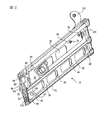
図1を参照すると、交換可能なマガジン10は、固定具14を製作品16内へ打ち込むための工具12に用いるように形成されている。多くの異なったタイプの固定具14がこのタイプの工具12には有益であり、これらの多くの異なったタイプの固定具のいかなる固定具もこのタイプの工具に適する。いろいろな長さを有する通常の釘14と同様に、クリップ釘およびPositive Placement用釘が使用され、該Positive Placement用釘は、飾り釘に加えて金属フレームへ突き通すように形成されている。”釘”という単語は、工具により打ち込まれる固定具14と工具自身の一部となる他の固定具とを区別をするために、ここ以降の説明の中で使用される。この単語を使用することにより、工具12に使用可能な固定具14の選択を制限するつもりはない。固定具14がマガジン10内に積み込まれるとき、各マガジン内の全ての固定具は一様なものである。
【0021】
図1に示されているマガジン10は、シャーブロック(せん断ブロック)20およびマガジンハウジング22を有する。好ましくは、シャーブロック20およびマガジンハウジング22は独立して構成されるが、シャーブロック20が一体化されたハウジング22が本マガジン10に使用されてもよい。
【0022】
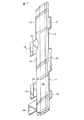
図2から図5に示されている一つの実施例においては、マガジンハウジング22は、二部品から構成されている。第一側部レール24は、頂縁26、底縁30、基端部32および末端部34を有する。第二側部レール36は、頂縁40、底縁42、基端部44および末端部46を有する。第二底縁42は、固定具を使用することなしに、第一側部レール24の底縁30に取り外し可能に取り付けられる。第一側部レールと第二側部レールとが互いに取り外し可能に取り付けられるとき、シャーブロック20は、第一側部レール24および第二側部レール36の各基端部32および44との間で保持される。シャーブロック20は第一位置決め要素47を有し、該第一位置要素は、第一側部レール24および第二側部レール36の少なくとも一つの上の第二位置決め要素48と係合する。任意ではあるが、第一位置決め要素47と第二位置決め要素48とが互いに係合し、且つシャーブロック20が第一側部レール24と第二側部レール36との間で差し込まれるとき、少なくとも一つの閉鎖手段49は第一側部レール24の頂縁26を第二側部レール36の頂縁40に保持する。
【0023】
好ましくは、第一側部レール24および第二側部レール36は、押し出しアルミニウム構造で作られる。金属は、比較的に安価で、頑丈で、所望の形状に容易に形成されるので、製造に好適な材料である。アルミニウムは、軽量化するのに好適な金属であるが、鋼や、特にステンレス鋼のような他の材料も考えられる。また、側部レールの製造に対しては、特にプラスチックのような他の材料の使用も考えられる。最も好適な材料は、窓部50、空洞部52、開口部54または他の細部が、このような細部の機械加工と比較し製造コストを下げるように各側部レール24,36内で打ち抜き型により打ち抜かれるか、または型成形されることを可能にする材料である。押し出し成形は、安価で側部レール24、36を作るのに好適な方法であるが、側部レールの製造に用いられる材料に適した任意の方法が使用可能である。
【0024】
基端部32,44は、マガジン10が使用のために工具12に設置されたときに、製作品16に最も接近する端部である。反対側の端部にある末端部34,46は、釘14が概してT形状のスロット53(図3)を通してマガジン10内へ積み込まれるときに該釘14が通る端部である。マガジン10が組み立てられるとき、第一側部レール24の基端部32は、第二側部レール36の基端部44と近接し、第一側部レール24の末端部34は、第二側部レール36の末端部46に近接する。マガジン10内に保持される釘14が連続的に使用されるように、各釘は、当該技術分野において知られているように例えば後述されるような付勢スプリングにより末端部34,46から基端部32,44の方へ動かされる。
【0025】
マガジン10が、工具12上にあって製作品16に使用するための準備が整っているとき、底縁30,42は、製作品16に最も近接する基端部32,44から末端部34,46へ延在する。頂縁26、40は、底縁30,42と対向し、基端部32,44から末端部34,46へ延在する。頂縁26,40は、底縁30,42より、製作品から離れている。
【0026】
図4,5(a),5(b)に最もよく示されているように、第一側部レール24の底縁30および第二側部レール36の底縁42は、固定具を使用すること無しに、互いに取り外し可能に取り付け可能である。一実施例においては、底縁30,42は、舌部60と溝部62との相補的な係合により互いに取り外し可能に取り付けられる。第一側部レール24の底縁30に沿った舌部60は、第二側部レール36の底縁42に沿った溝部62と交配的に係合する。以上、特定のマガジンの態様を示してが、第二側部レール36上に舌部60を有し、第一側部レール24上に溝部62を有するマガジンも全く同様の機能をなしうる。好ましくは、舌部60および溝部62は、側部レール24,36の長さ全体に沿って延在するが、工具12が繰り返し発射されることにより発生する応力を受けても、二つの側部レール24,36が一緒に保持されるように舌部60と溝部62との間で十分に相補的な係合をしているかぎり、側部レール24,36の長さ全体に沿って延在している必要はない。
【0027】
図4,5(a),5(b)をさらに参照すると、複数の固定具14がマガジン10の内側に嵌め込まれるように形成されており、マガジンは固定具を保持するのに十分な大きさの内部空洞部64を有することが必要とされる。マガジン10の深さは、頂壁66と底壁70とにより形成される。頂壁66と底壁70との両方が第一側部レール24の一部分であるように示されているが、多くの同等に満足する配置が可能である。頂壁66が側部レール24,36の一方の一部分に形成され、底壁が他方の側部レールの一部分に形成されることが可能であり、または、頂壁66と底壁70との両方が第二側部レール36から形成されることも可能である。工具12の方へ釘14を挿入し動かすために内部空洞部64内に十分な空間を提供するいかなる配置も本発明の使用に適する。
【0028】
図1および図2に示されるように、工具を使用するために工具12にマガジンが設置されたとき、マガジン10は、マガジン10の末端部34,46が基端部32,44より高い位置にある状態で、すなわち、製作品16から、より離れた状態で、筒部72に対して角度αで角度付けられている。この配置は、重力が工具12の方への釘14の動きを援助することを可能とする。マガジン10が角度付けられて設置されることは、当業者により、よく知られているが、その角度αは好ましくは20度から40度の範囲内である。
【0029】
任意ではあるが窓部50が切り取りによって側部レール24,36内に形成され、レール24,36の重量を軽減し、使用者がマガジン10内の釘14の動きを見ることを可能にする。例えば、もし、固定具14がマガジン10内で詰まったならば、詰まりはマガジンの外側から観察可能であり、使用者がマガジンを完全に分解しなければならないような事態を回避する。
【0030】
マガジン10は、第一側部レール24および第二側部レール36の各々の頂縁26,40に沿った少なくとも一つの閉鎖機構49により結合される。好ましくは、閉鎖機構49(図2)は、側部レール24,36の末端部34,46の方に配置される一つ以上のネジである。この配置においては、ネジ49を側部レール24,36の基端部32,44から離れて設置し、そこでは、ネジは、釘14との衝接の衝撃と釘14の打ち込みの衝撃とにより振動する可能性は少なく、ネジ49の振動および緩みを導くことも少ない。
【0031】
図2,図4、図5(a)および図5(b)を再度参照し、トラック76は、好ましくは、第二側部レール36の外側面で延在する。フォロワ(従動)組立体80(図2)は、釘14が工具12内に供給されるように、トラックに沿って滑動する。フォロワ(従動)組立体80は当業者により、よく知られている。一つの好適なフォロワ組立体80は、第二側部レール36の外側面上のトラック76上で保持され、マガジン10を通して末端部46から基端部44の方へ釘14を押す。第一側部レール24および第二側部レール36は、これらの間で複数の釘14を保持するために適当な大きさで形成される。第一側部レール24上の”C”形状のチャネル(通路)82は、釘頭部と係合することによりマガジン10の長さ方向に沿って内部空洞部64を通して釘14を案内する。少なくとも一つの全長に亘る窓部84は、好ましくは、フォロワ組立体80の一部分がマガジン内部の釘14に達し、工具10の方へ釘を押すことを可能にするために、マガジン10の長さ方向に亘って実質的に延在する。マガジン12が空になったとき、フォロワ組立体80はマガジン10の末端部46へ置きなおされ、マガジンに釘14が補充される。好ましくは、釘14は、釘ストリップ86(図6)の形態で供給され、通常、釘ストリップ86は、紙またはプラスチックのストリップに付けられた複数の釘を有する。ストリップ86は、釘14が内部空洞部64に沿って動き、製作品16内への放出のために連続的に筒部72内へ送り込まれるように、釘14を適当な所定位置で保持する。
【0032】
図2から図6を参照すると、シャーブロック20は、マガジン10の基端部32、44で、第一側部レール24と第二側部レール36との間で保持される。マガジン10が工具12に設置されると、シャーブロック20の面88は、鼻部材92のチャネル90に隣接する。面88およびチャネル90は、筒部72を形成するように形づくられており、該筒部を通して固定具14は製作品16内へ打ち込まれるように動く。釘がマガジン10から筒部72内へ移動するように、釘14は、シャーブロック領域94(図2)を通して、且つ、鼻部材92に隣接するシャーブロック20内の開口部96を通して動く。
【0033】
シャーブロック領域94は、特定の大きさまたはタイプの釘を受け入れるように形作られている。特定のシャーブロック20で使用されることが意図されていない釘14が使用されると、シャーブロック領域94が適当な大きさまたは形状でないことにより、釘14が適当に送り込まれず工具12の詰まりを引き起こす。シャーブロック20に対して釘14が大きすぎると、釘は、釘が高すぎるか、または幅があり過ぎて通過できない通路を遮蔽する。釘14が小さすぎる場合においては、釘は筒部72の側部から跳ね返され、打ち込みブレード(図示されていない)が降下し始めるまでに、部分的にシャーブロック領域94へ再突入する可能性がある。釘14がシャーブロック20のシャーブロック領域94内に部分的にしか置かれない場合でさえ、釘14上での打ち込みブレードの衝接は釘を下方向へ押し、釘はシャーブロック20と筒部72との間に詰め込まれ、工具12を動けなくする。
【0034】
本発明においては、シャーブロック20が工具12ではなくマガジン10に担持されるように適用されているがゆえに、詰まりは減ずる。本発明のマガジン10においては、釘14の分類に適応するようにシャーブロック20を変更することは容易である。シャーブロック20は、工具12の筒部72に隣接する開口部96を設置することにより、マガジン10に設置される。少なくとも一つの第一位置決め要素47および第二位置決め要素48により、シャーブロック20が第一側部レール24または第二側部レール36に当接して正しく設置されることが援助される。第一位置決め要素47は、シャーブロック20の一部分に配置され、該シャーブロック20は、マガジン10が組み立てられるとき、第一側部レール24または第二側部レール36と接触しうる。好ましくは、第一位置決め要素47はボスまたは他の突出物である。第二位置決め要素48は、第一側部レール24または第二側部レール36のどちらかに配置され、第一位置決め要素47と交配的に係合するように形成配置される。第二位置決め要素が適当に配置され適当な位置でシャーブロック20を保持するときに、第二位置決め要素48が第一位置決め要素47を捕まえてさえすれば、第二位置決め要素が穴部として示されているが、任意の窓部、開口部、空洞部または止め金でも第二位置決め要素として適する。
【0035】
好適な実施例においては、高い信頼性を有して所望の位置にシャーブロック20を保持するように、複数の第一位置決め要素47が複数の第二位置決め要素48と結合する。工具12の毎回の発射によりシャーブロック20を通して震える振動および衝撃は、ブロックを除去しようとする。第一側部レール24と第二側部レール36との間のシャーブロック20の摩擦係合と、摩擦力を増すための複数の位置決め機構47、48の使用により、シャーブロック20のしっかりとした設置と、ブロックの動きによる詰まりまたは摩耗の低減とを確実にする。
【0036】
シャーブロック20は、工具12が発射されるときにかかる力に耐えうる任意の材料から作られる。製造の材料としては金属が好適であり、アルミニウムまたは鋼が含まれるが、これらに制限されることはない。金属は、任意ではあるが、硬化処理、防錆処理または他の所望の特性を与える処理がなされる。最も好ましくは、シャーブロックは、焼き流し精密鋳造鋼で作られる。また、シャーブロック20の製造は、耐熱性または高強度重合体、セラミックスおよび、この適用に適する任意の他の材料が含まれる他の材料でもよい。
【0037】
図3および図6に示されるように、シャーブロック20は、好ましくは、一つ以上の脚部100(図6)を有し、該脚部100は、シャーブロック20の安定性を改良し、特に多数の第一位置決め要素が使用されている場合に都合のよい第一位置決め要素47の場所を提供する。脚部100はマガジン10が組み立てられるときに第一側部レール24と第二側部レール36との間で挟み込まれるように形成される。シャーブロック20がマガジンに設置されるとき、脚部100は、マガジン10の内部のシャーブロック20から末端部46の方へ延在する。もし、脚部100のいかなる部分もシャーブロック領域94内にあるならば、脚部100は、釘14が障害なしに内部空洞部64から筒部72へ通過することを可能にするように形成される。好ましくは、シャーブロック領域94は脚部100の内側に提供され、脚部は中空になっている。
【0038】
図1および図3を参照し、一つ以上の第一位置決め要素47は、少なくとも一つの脚部100に配置されている。脚部100に第一位置決め要素47を設置することにより、第二位置決め要素48が、側部レール24,36の基端部32,44の縁102(図1)から離れて設置されることを可能にする。もし、第二位置決め要素48が窓部またはスロットならば、第二位置決め要素48は、第二位置決め要素48が側部レール24、36により完全に囲まれるように、縁102から距離を置いて設置されなければならない。縁102から離れて第二位置決め要素48を設置することによって、側部レール24,36の領域における第二位置決め要素48の形状や方向性に関する柔軟性がさらに高められ、また、位置決め要素47,48が移動せしめられて振動源から離れる。
【0039】
シャーブロック20と、第一側部レール24および第二側部レール36との間で、第一位置決め要素47と第二位置決めレール48とを整列し、第一側部レールおよび第二側部レールの舌部60と溝部62とを整列し、閉鎖機構49とマガジンとを一緒に保持するように、閉鎖機構49をマガジンへ取り付けることにより、シャーブロック20の設置は容易に実現する。シャーブロック20の設置が容易になることにより、釘14の大きさ、またはタイプの変更が必要になったときのシャーブロックの交換をしやすくする。
【0040】
図1から図3を参照し、図7に最もよく示されているように、末端部34,46で、任意ではあるが、終端キャップ104が、マガジン10の第一側部レール24および第二側部レール36の端部を覆い、マガジン10の第一側部レール24および第二側部レール36に取り外し可能に取り付けられる。終端キャップ104は末端部34、46を保護し、マガジン10内への釘ストリップ86の挿入を援助する。終端キャップ104をマガジン10へ取り付ける方法においては、摩擦係合および固定具の使用が含まれる、いかなる方法も使用可能である。好ましくは、終端キャップ104は、ロック部110を備える少なくとも一つの可撓性の突起部106を有する。突起部106は、釘14の動きを妨害することなく、マガジン10の内部へ嵌め込まれるような大きさにされ、ロック部110が第一側部レール24または第二側部レール36のどちらかの窓部50の一つと係合するように配置される。マガジン10が再充填されるときにおいては、ロック部110を内部空洞部64の方へ押すことにより、突起部106が屈撓して、ロック部が移動して、係合されていた窓部50から出ることを可能にする。そして、終端キャップ104は、マガジン10から離れるように外側へ引っ張られることにより取り外される。最も好ましくは、終端キャップ104は複数の突起部106を有し、該突起部106は、側部レール24、36の複数の窓部50で固定される。終端キャップ104は、所定位置にスナップ式固定されるとき、マガジン10の第一側部レール24および第二側部レール36を一緒に保持することを助け、マガジンの末端部の安定性を増す。もし、固定が十分きっちりとしたものであるならば、終端キャップ104はマガジン10を一緒に保持し、第一側部レール24と第二側部レール36とを一緒に保持するための固定具の必要性を排除することが考えられる。
【0041】
好適な終端キャップ104は、終端キャップが設置されるときにマガジン10に隣接する傾斜が付けられた側部112と、該傾斜が付けられた側部と対向する幅広の側部114とを有するように形成される。突起部106は、内部空洞部64内への挿入のために、傾斜が付けられた側部112から外側方向へ延在する。終端キャップ104の幅広の側部114内への釘ストリップ86の挿入は、一つ以上のシェルフユニット116の存在により援助され、該シェルフユニットは、釘ストリップを案内し支持する幅広の側部から外側へ延在する。
【0042】
図6を参照すると、マガジン10の基端部46で、シャーブロック20は、連結機構120を有し、該連結機構120はマガジンを工具12上へ正確に位置決めし、釘14をマガジンから筒部へ連続的に送り込むように、開口部96(図1)を筒部72と整列する。当該技術分野において知られている、任意の連結機構120の使用が考えられるが、好ましくは、連結機構は、鼻部材92上の複数の設置ピンであり、該設置ピンはシャーブロック20の穴部124と係合する。
【0043】
マガジン10の末端部34,46でブラケット126(図2)は工具12に取り付けられ、該ブラケット126は、シャーブロック20およびマガジン10を所定の位置にしっかりと保持する。もし、マガジン10が詰まりを起こしたならば、マガジンが連結機構120周りに旋回し、部分的に筒部72を開口するように、ブラケット126を緩めることが可能である。マガジン10がこの位置にあるときにおいては、詰まりは、マガジン全体を取り外すよりも、より早くより簡単に除去可能とされる。連結機構120を締め付けることにより、使用者が最小の中断時間で工具12を作業状態に復帰することを可能にする。
【0044】
図1を参照すると、マガジン10が所定の位置にあり、工具12は固定具14の製作品16内への打ち込みに使用されることが可能である。工具の全体的なデザインおよび操作は当業者により、よく知られており、参照として取り込まれた前述の特許に記載されている。動力源130は工具ハウジング132内に配置される。鼻部材92は、工具ハウジング132へ取り付けられ、マガジン10に隣接する。マガジン10を設置することにより、面88とチャネル90とにより筒部72が形成される。固定具14は、シャーブロック領域96を通して、マガジンの内部空洞部64から筒部72内へ動く。動力源130からの動力は打ち込みブレード(図示されていない)にエネルギーを与え、打ち込みブレードは、筒部72を通して固定具14を製作品16内へ動かす。
【0045】
固定具のタイプを変更する能力を十分に活かすために、時には、工具12に対して他の変更が必要とされる。普通の釘14に対しては、単一のアルミニウム製の鼻部材92が通常使用される。特定タイプの固定具14が使用されるときは、代替の製作品接触要素138が使用され、そのいくつかは他のものよりも重い。一般的に、鼻部材92の製造に好適な材料は、軽量であるがゆえにアルミニウムであるが、アルミニウムは、より重い製作品接触要素138の一つを支持する十分な強度はない。このような場合においては、鋼製の鼻部材92を利用することが好都合となる。
【0046】
図6を参照すると、任意ではあるが、鼻部材92は前面当板(または防摩板)144および背面当板(または防摩板)146の二つの部品に分離されているので、鼻部材92は、任意の製作品接触要素138とともに利用されることが可能である。前面当板144は、製作品接触要素138を保持し、鋼で作られており、背面当板146は、工具12が重くなりすぎることを妨げるために、アルミニウムまたは硬化金属シートのような軽量材料で作られることが可能である。本発明のマガジン10とともに、分離される鼻部材92を使用することは、マガジン10およびシャーブロック20の交換のみならず背面当板146および製作品接触要素138の交換を可能し、工具12に一定の柔軟性を提供する。
【0047】
好適な鼻部材92は、異なったタイプの釘14が使用される場合の交換のために取り外し可能な背面当板146を有する。釘14には多くの異なった直径および異なった頭部形態のものがある。丸頭釘14は円形状の頂上部を有し、クリップ釘はD形状の頭部を有する。クリップ釘14を使用するとき、頭部の丸い部分が筒部72に入り、丸頭釘とほぼ同じ位置に置かれる。しかし、頭部は平坦な面を有するので、打ち込みブレードは平坦な面の縁へ最も接近する。釘14または打ち込みブレードのどちらかが位置ずれしたならば、打ち込みブレードは頭部の平坦な縁をはずし、釘14を完全にはずし、工具12を動けなくする。より浅いチャネル(溝または通路)90を有する背面当板146に変更することにより、釘14がチャネル内に深く置かれることを妨げる。釘頭部は、打ち込みブレードに対して、より正確に中心に置かれ、打ち込みブレードが釘14を外す可能性を減ずる。本発明の一つの実施例においては、丸頭釘用のチャネル90の深さは、0.81mm(0.032インチ)であり、クリップ頭釘用のチャネルの深さは、0.3mm(0.012インチ)である。この特徴は、丸頭釘およびクリップ釘という点で記載されたが、多くのタイプの釘に利用可能であることは、当業者により理解されうる。
【0048】
工具12の使用を便利にするためのいくつかの任意の特徴が本発明のマガジン10へ加えられることが可能である。図2に示されように、固定具が打ち込まれうる深さを指し示すように、線または細切れなマーク150がマガジン10へ加えられることが可能である。好適には、マーク150はシャーブロック20上に有する。釘14がシャーブロック20に入るとき、釘は、シャーブロック20の側部の任意の開口部152を通して目に見える。マーク150は、工具12が使用中の間は、固定具14の長さにより部分的に覆い隠される。マガジン10内の固定具14の長さは、固定具の長さを越えて見えるマーク150の数により判断される。
【0049】
図2から図5を参照すると、マガジン10は、シャーブロック20上の第一位置決め要素47を、側部レール24,36の少なくとも一つの上の第二位置決め要素48と係合することにより組み立てられ、シャーブロック20は、使用される固定具14のタイプとの互換性に基づいて選択される。次ぎに、舌部60が、底縁30,42で溝部62内に挿入され、頂縁26,40がくっつけられ、二つの側部24、36の間でシャーブロック20を挟み込む。側部24,36は、閉鎖機構49、あるいは終端キャップ104により、または、これらの両方を設置することにより、一緒に保持される。終端キャップ104の設置には、ロック部110が側部レール24,36の一つの窓部50または他の開口部52と係合するまで、傾斜付き側部112の突起部106を挿入することが含まれる。釘は終端キャップ104を通してマガジン10の内部空洞部64内へ挿入され、好ましくは、釘ストリップがマガジン10へ入るとき、シェルフ116上で釘ストリップ86を支持する。もしシャーブロック20を変更する必要が生じたならば、上記の工程が逆にされ、異なったシャーブロックが使用され、マガジンが再組立される。
【0050】
釘14が内部空洞部64を通して移動するとき、釘は、釘を収容するように形作られたシャーブロック領域94でシャーブロック20を通過する。シャーブロック領域94を通過したのち、釘は工具12の筒部72へ入る。工具12が発射されると、打ち込みブレードによる力は、筒部72の長さ方向に釘14を押しながら下方向に移動し、釘14を製作品16内へ移動する。
【0051】
図6を参照すると、マガジン10は、鼻部材92上の設置ピン120をシャーブロック20の穴部124と結合することにより、工具12上に設置される。マガジン10の末端部で、取り付けブラケット126は固定具125により工具12に取り付けられる。いくつかの詰まりは、取り付けブラケット126を解放し、マガジン10が設置ピン120上で旋回することができるようにすることにより、除去可能となる。他の場合においては、マガジン10全体を工具12から取り外されなければならないようなこともある。固定具14のタイプは、取り付けブラケット126を解放し、設置ピン120からマガジンを持ち上げることにより、作業中に、容易に変更可能である。新しいマガジン10が入手され、設置ピン120が穴部114と整列され穴部114内へ挿入され、取り付けブラケット116が取り付けられる。マガジン10が取り外されることにより、異なった製作品接触要素138または異なったチャネル90を適応する必要があるとき、前面当板144および背面当板146は変更されることが可能である。
【0052】
工具用の取り外し可能なマガジンの特定の実施例を図示し説明してきたが、より広い態様および特許請求の範囲における発明から逸脱しない変形および変更が可能であることは、当業者により理解されうる。
【図面の簡単な説明】
【図1】本工具の正面斜視図である。
【図2】図1のマガジンの正面斜視図である。
【図3】第二側部レールが取り外された状態の、マガジンの正面斜視図である。
【図4】第一側部レールの側面図である。
【図5】(a)第二側部レールの側面図である。
(b)底縁が交配的に係合されている状態の第一側部レールおよび第二側部レールの側面図である。
【図6】図2のシャーブロックおよび鼻部材の部分斜視図である。
【図7】終端キャップの正面図である。
【符号の説明】
10…マガジン
12…工具
16…製作品
20…シャーブロック
22…マガジンハウジング
72…筒部
92…鼻部材
130…動力源
132…工具ハウジング[0001]
BACKGROUND OF THE INVENTION
The present invention relates to portable combustion fixture driving tools, and in particular to replaceable magazines for such tools.
[0002]
[Prior art]
Portable combustion tools that are used to drive the fixture into the work are known (see
[0003]
The tool thus has a generally gun-shaped tool housing that surrounds a small internal combustion engine. The engine is powered by a pressurized fuel gas container, also called a fuel cell. A battery-powered power distribution unit or power transmission unit generates sparks for ignition, and a fan disposed within the combustion chamber provides efficient combustion within the chamber and also includes scavenging air containing exhaust of combustion products Also make it easier. The engine has a reciprocating piston that has an elongated, rigid drive blade that is disposed in the piston chamber of the cylinder body.
[0004]
The wall of the combustion chamber is capable of axial reciprocation relative to the valve sleeve and links when the product contact element or nose member assembly at the end of the nose member is coupled to the linkage and pressed against the product. Moves through the mechanism to close the combustion chamber. This pressing action also causes the insertion of a defined volume of fuel gas from the fuel cell into the combustion chamber.
[0005]
When triggered to trigger the ignition of the gas in the combustion chamber, the piston and driving blade are moved downwards to abut the fixture in place and drive the fixture into the work piece. . When the piston is moved downward, the displacement volume enclosed in the piston chamber below the piston is forcibly discharged from one or more discharge ports provided at the lower end of the cylinder. After impingement, the piston returns to its original or “ready” position due to the pressure difference of the gas in the cylinder. The fixture is fed from the supply assembly into the nose member barrel, where the fixture is held in an appropriate orientation to receive the impact of the driving blade. The fixture is moved over the length of the cylinder by the driving blade and exits from the cylinder on the surface of the product. The force of the driving blade and the movement of the fixture will drive the fixture through the work piece.
[0006]
A convenient way to supply the fixture is to feed the fixture continuously through the magazine into the tube. When the magazine is empty, it is removed from the nail gun and refilled and reinstalled to continue work. Multiple magazines are often used so that the craftsman can continue working while the magazine is refilled by an assistant or stored to be refilled later. Replacement between many different types of fixtures is often required. For example, nails may be general or for Positive Placement (R), clip heads, Roundriv (R) or of various lengths. The geometry of the magazine and shear block area (shear area) that hold the fixture in the proper orientation to accept the impact of the driving blade determines the type of fastener that fits the particular magazine or shear block area. .
[0007]
The firing of the tool causes significant impact and vibration when the driving blade strikes the fixture and drives the fixture into the work piece. Screws proximate to the shear block area that are often required to be tightened to properly hold the component parts tend to loosen due to vibration. For this reason, the magazine has usually been a single structure. In the prior art, a magazine having a plurality of components is fixed by screws in the vicinity of a shear block (shear block). In many cases, the screws that connect the side rails of the magazine are loosened by repeated vibrations over time. In using such a magazine, the magazine must be inspected periodically to determine if the fixture needs to be tightened. This need for monitoring is the most inconvenient.
[0008]
Single part magazines have been used in the art in an attempt to eliminate the dismantling of the magazine. However, it has been found that units made of a single part are very heavy or very expensive to manufacture. The side window of the magazine reduces weight and allows the user to visually check the operation of the magazine. It is not easy to stamp, punch or mold a single part magazine to create a window and an internal cavity through which the fixture passes. In order to manufacture this type of magazine, more expensive manufacturing techniques must be used.
[0009]
Prior art combustion tools have removable magazines, but are not necessarily modifiable to handle different sizes and types of fixtures. This is because the shear block area guides the fixture into the cylinder, and the type of fixture that can be used is determined by the shear block that surrounds the shear block area and becomes a permanent part of the tool. Removable magazines can be used to provide a convenient supply of fixtures, but fixtures that can be handled by changing from one magazine to another as long as the shear block area is not replaced The size and shape of the head cannot be changed.
[0010]
It is known in the art to adapt to changes in the length of the fixture by moving the lever. If the user forgets to move the lever or sets it in the wrong place, the fixture may become clogged in the tube of the tool. At that time, before the operation is resumed, the cylinder part must be opened to remove the clogging. It is conceivable that the use of a lever to accommodate changes in fixture diameter or head shape can produce similar results.
[0011]
The inclusion of the shear block in the tool makes it impossible to use the tool if the shear block is damaged. If the shear block needs to be repaired or replaced, the entire tool will be disabled during the repair period and the user will need to have another tool as a spare, or else It is necessary to change the work schedule until the tool is available.
[0012]
[Patent Document 1]
Reissued US Pat. No. 32,452
[Patent Document 2]
U.S. Pat. No. 4,403,722
[Patent Document 3]
U.S. Pat. No. 4,483,473
[Patent Document 4]
US Pat. No. 4,483,474
[Patent Document 5]
U.S. Pat. No. 4,552,162
[Patent Document 6]
US Pat. No. 5,197,646
[Patent Document 7]
US Pat. No. 5,263,439
[Patent Document 8]
US Pat. No. 6,016,622
[0013]
[Problems to be solved by the invention]
Thus, there is a need in the art for a removable magazine for tools that accommodates different sizes and types of fixtures. There is also a need for a magazine that does not have screws that are loosened by vibration near the shear block. Furthermore, there is a need for a tool that accommodates a magazine with an integrated shear block so that the shear block can be changed by simply attaching a different magazine to the tool.
[0014]
[Means for Solving the Problems]
The present invention features a removable magazine for power tools that holds different sized or types of fixtures and is interchangeable with a similar magazine for use with the same tool.
[0015]
Furthermore, the present invention provides a tool for driving a fixture from a removable magazine. The tool includes a tool housing having a proximal end and a distal end, and a power source surrounded by the housing. The nose member is attached to the housing and has a channel (passage) and a first alignment mechanism. The magazine is detachably attached to the tool, and has a magazine housing and a shear block (shear block) attached to a proximal end portion of the magazine housing. The shear block has a second alignment mechanism and a surface, and when the first alignment mechanism is engaged with the second alignment mechanism and the magazine is removably attached to the tool, the second alignment mechanism and the surface Forms a cylinder. When the tool is fired, the fixture is moved into the work piece through the tube by a power source.
[0016]
When the fixture is moved from the magazine into the barrel, the fixture passes through the shear block, which is formed for a specific size and type of fixture and holds the fixture within the barrel for firing. Assist with proper alignment. By attaching the shear block onto the magazine, it is possible to change the shear block each time the magazine is replaced, allowing for rapid conversion to a different fixture. No valuable time is spent manually checking the lever position, changing the lever, or removing the clogging when an incompatible lever position is selected.
[0017]
In the preferred embodiment, a two-part structured magazine is used. The magazine housing is made of a first side rail and a second side rail that are mated and engaged with each other. When the first side rail and the second side rail are detachably attached to each other, the shear block is held between the base ends of the first side rail and the second side rail.
[0018]
The fact that the magazine is composed of two parts offers many advantages over the prior art. The window portion arranged on each rail in order to reduce the weight of the magazine can be punched out by a punching die when the thickness of the material is uniform. In a single part magazine, punching with a punching die is not possible. The windows are generally obtained by machining each window, resulting in more labor and higher costs. When each side rail is punched out by a punching die prior to assembly, the magazine can be made lighter and faster at a lower cost compared to a single part magazine. Further, each side rail can be independently replaced by a two-part magazine, so that more economical repair is possible.
[0019]
The magazine is easily assembled by engaging the tongue on one side rail with the groove on the bottom edge of the other side rail, and then a fixture is provided at the upper end of the magazine. When a fixture is used to hold the magazine together in the vicinity of the barrel, the fixture is loosened by impact and vibration with each firing of the tool. By using the tongue and groove assembly, the magazine is held together in such a way that the fixture does not loosen. Also, in this structure, since a small number of fixtures are required, the magazine is easily assembled.
[0020]
DETAILED DESCRIPTION OF THE INVENTION
Referring to FIG. 1, a
[0021]
The
[0022]
In one embodiment shown in FIGS. 2-5, the
[0023]
Preferably, the
[0024]
The proximal ends 32 and 44 are the ends closest to the
[0025]
When the
[0026]
As best shown in FIGS. 4, 5 (a) and 5 (b), the
[0027]
With further reference to FIGS. 4, 5 (a), 5 (b), a plurality of fixtures 14 are formed to fit inside the
[0028]
As shown in FIGS. 1 and 2, when a magazine is installed on the
[0029]
A
[0030]
The
[0031]
Referring again to FIGS. 2, 4, 5 (a) and 5 (b), the
[0032]
2 to 6, the
[0033]
The
[0034]
In the present invention, since the
[0035]
In the preferred embodiment, a plurality of
[0036]
The
[0037]
As shown in FIGS. 3 and 6, the
[0038]
With reference to FIGS. 1 and 3, one or more
[0039]
The
[0040]
1-3, as best shown in FIG. 7, at the
[0041]
A
[0042]
Referring to FIG. 6, at the
[0043]
A bracket 126 (FIG. 2) is attached to the
[0044]
Referring to FIG. 1, the
[0045]
Other changes to the
[0046]
Referring to FIG. 6, the
[0047]
A
[0048]
Several optional features for convenient use of the
[0049]
With reference to FIGS. 2-5, the
[0050]
As the nail 14 moves through the
[0051]
Referring to FIG. 6, the
[0052]
While specific embodiments of a removable magazine for tools have been illustrated and described, it will be appreciated by those skilled in the art that variations and modifications can be made without departing from the invention in its broader aspects and claims.
[Brief description of the drawings]
FIG. 1 is a front perspective view of the tool.
FIG. 2 is a front perspective view of the magazine of FIG.
FIG. 3 is a front perspective view of the magazine with the second side rail removed.
FIG. 4 is a side view of the first side rail.
FIG. 5A is a side view of a second side rail.
(B) It is a side view of the 1st side rail and the 2nd side rail of the state in which the bottom edge is matingly engaged.
6 is a partial perspective view of the shear block and the nose member of FIG. 2. FIG.
FIG. 7 is a front view of the end cap.
[Explanation of symbols]
10 ... Magazine
12 ... Tool
16 ... Production
20 ... Sherlock
22 ... Magazine housing
72 ... Cylinder part
92 ... Nose member
130 ... Power source
132 ... Tool housing
Claims (7)
工具ハウジングと、
前記工具ハウジングにより囲まれる動力源と、
前記工具ハウジングに取り付けられ、チャネルと第一連結機構を有する鼻部材と、
前記工具に取り外し可能に取り付けられるマガジンとを具備し、
前記マガジンは、基端部および末端部を有するマガジンハウジングと、前記マガジンハウジングの前記基端部に取り付けられるシャーブロックとを有し、
前記シャーブロックは、第二連結機構と、面とを有し、
前記チャネルおよび前記面は、前記第一連結機構が前記第二連結機構と係合されるときに筒部を形成し、
前記マガジンは、前記固定具が前記筒部を通して製作品内へ前記動力源により動かされるように、前記工具に取り外し可能に取り付けられ、
前記マガジンハウジングは、少なくとも第一側部レールと第二側部レールとを具備し、 前記シャーブロックは、前記第一側部レールおよび前記第二側部レールの基端部との間で挟み込まれ、
前記シャーブロックは、前記第一側部レールおよび前記第二側部レールの少なくともいずれか一方の側部レール上に配置された第二位置決め要素と係合可能な第一位置決め要素を具備する、工具。 A tool for driving a fixture from a removable magazine,
A tool housing;
A power source surrounded by the tool housing;
A nose member attached to the tool housing and having a channel and a first coupling mechanism ;
A magazine removably attached to the tool,
The magazine has a magazine housing having a base end portion and a distal end portion, and a shear block attached to the base end portion of the magazine housing,
The shear block has a second coupling mechanism and a surface,
The channel and the surface form a cylindrical portion when the first coupling mechanism is engaged with the second coupling mechanism ,
The magazine, the so fixture is moved by the power source into the manufacturing work through the tubular portion, releasably attached to the tool,
The magazine housing includes at least a first side rail and a second side rail, and the shear block is sandwiched between base ends of the first side rail and the second side rail. ,
The shear block includes a first positioning element engageable with a second positioning element disposed on at least one of the first side rail and the second side rail. .
前記第一位置決め要素は前記脚部上に配置される、請求項1に記載の工具。 The tool of claim 1, wherein the first positioning element is disposed on the leg.
Applications Claiming Priority (1)
| Application Number | Priority Date | Filing Date | Title |
|---|---|---|---|
| US10/170,991 US6679414B2 (en) | 2002-06-13 | 2002-06-13 | Interchangeable magazine for a tool |
Publications (3)
| Publication Number | Publication Date |
|---|---|
| JP2004017280A JP2004017280A (en) | 2004-01-22 |
| JP2004017280A5 JP2004017280A5 (en) | 2006-07-06 |
| JP4387698B2 true JP4387698B2 (en) | 2009-12-16 |
Family
ID=29583849
Family Applications (1)
| Application Number | Title | Priority Date | Filing Date |
|---|---|---|---|
| JP2003169269A Expired - Fee Related JP4387698B2 (en) | 2002-06-13 | 2003-06-13 | tool |
Country Status (13)
| Country | Link |
|---|---|
| US (1) | US6679414B2 (en) |
| EP (1) | EP1371456B1 (en) |
| JP (1) | JP4387698B2 (en) |
| KR (1) | KR20030095991A (en) |
| CN (1) | CN1328015C (en) |
| AT (1) | ATE416067T1 (en) |
| AU (1) | AU2003204598B2 (en) |
| CA (1) | CA2432091C (en) |
| DE (1) | DE60324987D1 (en) |
| DK (1) | DK1371456T3 (en) |
| ES (1) | ES2316701T3 (en) |
| PT (1) | PT1371456E (en) |
| TW (1) | TWI241944B (en) |
Families Citing this family (49)
| Publication number | Priority date | Publication date | Assignee | Title |
|---|---|---|---|---|
| US7971768B2 (en) * | 2004-05-04 | 2011-07-05 | Illinois Tool Works Inc. | Guidance system for fasteners |
| US20060118594A1 (en) * | 2004-12-03 | 2006-06-08 | Robert Chen | Nailing gun with improved nail magazine |
| US20070075112A1 (en) * | 2005-10-04 | 2007-04-05 | Porth Chris H | Nose assembly for a fastener driving tool |
| US20070251970A1 (en) * | 2006-02-28 | 2007-11-01 | Cox Pamela L | Spring-loaded desktop stapler with interchangeable staple cartridges |
| US7942299B2 (en) | 2006-05-31 | 2011-05-17 | Black & Decker Inc. | Hand tool with belt or rafter hook |
| EP1872962B1 (en) * | 2006-06-23 | 2011-09-28 | Müller Martini Holding AG | Stapling device for printed products having a ceramic component |
| US20080067212A1 (en) * | 2006-09-14 | 2008-03-20 | Wan-Fu Wen | Magazine for Nail Gun |
| EP2083969B1 (en) * | 2006-10-20 | 2013-01-02 | Stanely Fastening Systems, L.P. | Fastener driving device with mechanisms to limit movement of nails |
| TWI434754B (en) * | 2007-08-17 | 2014-04-21 | Rexon Ind Corp Ltd | Nailer rotation device |
| CN101925442B (en) * | 2008-01-29 | 2012-08-15 | 钉密封有限公司 | Recess filling apparatus |
| US8181836B2 (en) | 2008-09-03 | 2012-05-22 | Illinois Tool Works Inc. | Rotary fastener magazine |
| CA2736521A1 (en) * | 2008-09-09 | 2010-03-18 | Sonette Myburgh, Trustee For The Herman Myburgh Preservation Trust | Nail driving tool mechanism |
| TWI409145B (en) * | 2010-01-22 | 2013-09-21 | Apex Mfg Co Ltd | Nailing device adapted for nail units with different sizes |
| US8061437B2 (en) * | 2010-03-04 | 2011-11-22 | De Poan Pneumatic Corp. | Nail gun with rapidly attachable and detachable magazine assembly |
| US8302831B2 (en) | 2010-04-13 | 2012-11-06 | Illinois Tool Works Inc. | Flanged fuel cell and locating structure for combustion tool |
| US8939339B2 (en) | 2010-04-13 | 2015-01-27 | Illinois Tool Works Inc. | Interface for fuel delivery system for combustion nailer |
| US9802303B2 (en) | 2010-04-13 | 2017-10-31 | Illinois Tool Works Inc. | Interface for fuel delivery system for combustion fastener driver |
| US20110278342A1 (en) * | 2010-05-17 | 2011-11-17 | De Poan Pneumatic Corp. | Nail gun with improved attachable and detachable magazine assembly |
| US8833628B2 (en) | 2011-03-09 | 2014-09-16 | Illinois Tool Works Inc. | Tool free interchangeable fastener guide |
| US9522464B2 (en) | 2011-05-16 | 2016-12-20 | Illinois Tool Works Inc. | Multi-position utility hook assembly for a tool |
| DE202012004325U1 (en) * | 2012-05-03 | 2013-08-08 | Illinois Tool Works Inc. | Nail-driving tool |
| US9498871B2 (en) | 2012-05-31 | 2016-11-22 | Black & Decker Inc. | Power tool raving spring curl trip actuator |
| US9827658B2 (en) | 2012-05-31 | 2017-11-28 | Black & Decker Inc. | Power tool having latched pusher assembly |
| US9486904B2 (en) | 2012-05-31 | 2016-11-08 | Black & Decker Inc. | Fastening tool nosepiece insert |
| US11229995B2 (en) | 2012-05-31 | 2022-01-25 | Black Decker Inc. | Fastening tool nail stop |
| US9469021B2 (en) * | 2012-05-31 | 2016-10-18 | Black & Decker Inc. | Fastening tool nail channel |
| US9649755B2 (en) | 2012-05-31 | 2017-05-16 | Black & Decker Inc. | Power tool having angled dry fire lockout |
| US10414033B2 (en) | 2012-10-04 | 2019-09-17 | Black & Decker Inc. | Power tool hall effect mode selector switch |
| US11077542B2 (en) * | 2013-10-31 | 2021-08-03 | Stanley Fastening Systems, L.P. | Metal connector adaptor for a fastening tool |
| NZ722047A (en) | 2014-03-03 | 2017-10-27 | Illinois Tool Works | Interface for fuel delivery system for combustion fastener driver |
| USD756739S1 (en) * | 2014-06-02 | 2016-05-24 | Stanley Fastening Systems, L.P. | Pneumatic nailer |
| USD756740S1 (en) * | 2014-06-02 | 2016-05-24 | Stanley Fastening Systems, L.P. | Pneumatic nailer |
| CN208289826U (en) | 2015-02-06 | 2018-12-28 | 米沃奇电动工具公司 | Using gas spring as the fastener driver of power |
| TWM517078U (en) * | 2015-10-02 | 2016-02-11 | Basso Ind Corp | Nail gun with protective structure |
| US10668608B2 (en) | 2016-02-10 | 2020-06-02 | Illinois Tool Works Inc. | Fastener driving tool |
| US11325235B2 (en) | 2016-06-28 | 2022-05-10 | Black & Decker, Inc. | Push-on support member for fastening tools |
| US11267114B2 (en) * | 2016-06-29 | 2022-03-08 | Black & Decker, Inc. | Single-motion magazine retention for fastening tools |
| US10987790B2 (en) | 2016-06-30 | 2021-04-27 | Black & Decker Inc. | Cordless concrete nailer with improved power take-off mechanism |
| US11400572B2 (en) | 2016-06-30 | 2022-08-02 | Black & Decker, Inc. | Dry-fire bypass for a fastening tool |
| US20180093370A1 (en) * | 2016-10-04 | 2018-04-05 | Stanley Black & Decker, Inc. | Fastening Tool with Contact Arm and Multi-Fastener Guide |
| CN108058138B (en) * | 2016-11-09 | 2022-11-25 | 创科无线普通合伙 | Depth of drive adjustment mechanism for gas spring fastener driver |
| US10926385B2 (en) | 2017-02-24 | 2021-02-23 | Black & Decker, Inc. | Contact trip having magnetic filter |
| USD854820S1 (en) | 2017-11-14 | 2019-07-30 | Illinois Tool Works Inc. | Fastener driving tool belt hook |
| USD855431S1 (en) | 2017-11-14 | 2019-08-06 | Illinois Tool Works Inc. | Fastener driving tool pipe hook |
| US10926391B2 (en) | 2017-11-14 | 2021-02-23 | Illinois Tool Works Inc. | Powered fastener driving tool having hook assemblies |
| US11433521B2 (en) | 2019-03-13 | 2022-09-06 | Milwaukee Electric Tool Corporation | Powered fastener driver |
| US20200316762A1 (en) * | 2019-04-04 | 2020-10-08 | James Laplaunte | Modified cap nail securing system |
| EP4112229A4 (en) * | 2020-02-28 | 2023-09-20 | Hangzhou Great Star Industrial Co., Ltd. | Staple box component, staple gun, and method for replacing staple box component of staple gun |
| EP4082761B1 (en) * | 2021-04-30 | 2024-03-27 | DB Imagineering BV. | Repair injector with support device for laminated glass |
Family Cites Families (20)
| Publication number | Priority date | Publication date | Assignee | Title |
|---|---|---|---|---|
| US4483474A (en) * | 1981-01-22 | 1984-11-20 | Signode Corporation | Combustion gas-powered fastener driving tool |
| US4463888A (en) * | 1981-04-22 | 1984-08-07 | Duo-Fast Corporation | Fastener driving tool |
| US4597517A (en) | 1985-06-21 | 1986-07-01 | Signode Corporation | Magazine interlock for a fastener driving device |
| US4815647A (en) * | 1986-11-10 | 1989-03-28 | Chou Joseph S Y | Multiple-function magazine for tee nails to be used with a nailing gun |
| IT216379Z2 (en) * | 1989-01-18 | 1991-07-18 | Fasco Spa | MAGAZINE FOR NAILING PISTOL |
| JPH04365567A (en) * | 1991-06-12 | 1992-12-17 | Makita Corp | Pusher device for nail driver |
| US5197647A (en) * | 1991-10-21 | 1993-03-30 | Illinois Tool Works Inc. | Fastener-driving tool with improved feeding mechanism |
| US5263439A (en) * | 1992-11-13 | 1993-11-23 | Illinois Tool Works Inc. | Fuel system for combustion-powered, fastener-driving tool |
| US5297713A (en) * | 1993-03-31 | 1994-03-29 | Stanley-Bostitch, Inc. | Rear load magazine assembly |
| US5335800A (en) * | 1993-07-06 | 1994-08-09 | Liu Chung Ho | Magazine for rivet gun |
| US5350103A (en) * | 1993-07-13 | 1994-09-27 | Umberto Monacelli | Easy fastener jam removal tool |
| US5433367A (en) * | 1994-11-28 | 1995-07-18 | Liu; Park | Magazine assembly for a fastener driving tool |
| DE29505437U1 (en) * | 1995-03-30 | 1995-08-17 | Chiu Gin Liang | Standard magazine for a stapler |
| JPH08290370A (en) * | 1995-04-19 | 1996-11-05 | Japan Power Fastening Co Ltd | Gas combustion-type portable driving tool |
| DE29611517U1 (en) * | 1996-02-29 | 1996-10-02 | Prebena Wilfried Bornemann | Device for driving in lined connecting elements composed of head pieces and shafts ending in striking tips |
| US5839638A (en) * | 1997-06-26 | 1998-11-24 | Illinois Tool Works Inc | Pneumatic trim nailer |
| US6012622A (en) | 1998-04-20 | 2000-01-11 | Illinois Tool Works Inc. | Fastener driving tool for trim applications |
| US6053389A (en) * | 1998-08-05 | 2000-04-25 | Sup Drogon Enterprise Co., Ltd. | Nailing gun magazine specially designed for big nail set |
| US6131787A (en) | 1999-07-27 | 2000-10-17 | Illinois Tool Works Inc. | Two-piece nailer magazine and method therefor |
| US6189759B1 (en) * | 1999-08-06 | 2001-02-20 | Stanley Fastening Systems, Lp | Fastener driving device with enhanced magazine latch assembly |
-
2002
- 2002-06-13 US US10/170,991 patent/US6679414B2/en not_active Expired - Lifetime
-
2003
- 2003-05-01 TW TW092112060A patent/TWI241944B/en not_active IP Right Cessation
- 2003-06-03 KR KR10-2003-0035702A patent/KR20030095991A/en not_active Application Discontinuation
- 2003-06-10 AU AU2003204598A patent/AU2003204598B2/en not_active Expired
- 2003-06-11 CN CNB031407811A patent/CN1328015C/en not_active Expired - Fee Related
- 2003-06-12 CA CA002432091A patent/CA2432091C/en not_active Expired - Lifetime
- 2003-06-13 DE DE60324987T patent/DE60324987D1/en not_active Expired - Fee Related
- 2003-06-13 ES ES03291410T patent/ES2316701T3/en not_active Expired - Lifetime
- 2003-06-13 DK DK03291410T patent/DK1371456T3/en active
- 2003-06-13 EP EP03291410A patent/EP1371456B1/en not_active Expired - Lifetime
- 2003-06-13 JP JP2003169269A patent/JP4387698B2/en not_active Expired - Fee Related
- 2003-06-13 AT AT03291410T patent/ATE416067T1/en not_active IP Right Cessation
- 2003-06-13 PT PT03291410T patent/PT1371456E/en unknown
Also Published As
| Publication number | Publication date |
|---|---|
| CN1328015C (en) | 2007-07-25 |
| EP1371456A3 (en) | 2004-04-14 |
| US20030230622A1 (en) | 2003-12-18 |
| EP1371456B1 (en) | 2008-12-03 |
| TWI241944B (en) | 2005-10-21 |
| US6679414B2 (en) | 2004-01-20 |
| AU2003204598B2 (en) | 2006-02-02 |
| PT1371456E (en) | 2009-02-20 |
| KR20030095991A (en) | 2003-12-24 |
| CA2432091C (en) | 2007-04-17 |
| DE60324987D1 (en) | 2009-01-15 |
| CA2432091A1 (en) | 2003-12-13 |
| CN1468690A (en) | 2004-01-21 |
| TW200404652A (en) | 2004-04-01 |
| ATE416067T1 (en) | 2008-12-15 |
| ES2316701T3 (en) | 2009-04-16 |
| EP1371456A2 (en) | 2003-12-17 |
| AU2003204598A1 (en) | 2004-01-15 |
| DK1371456T3 (en) | 2009-03-16 |
| JP2004017280A (en) | 2004-01-22 |
Similar Documents
| Publication | Publication Date | Title |
|---|---|---|
| JP4387698B2 (en) | tool | |
| JP4316927B2 (en) | Nose member and shear block assembly for a tool for driving a fixture supplied from a plurality of fixtures | |
| JP4261117B2 (en) | Driving tool | |
| USRE41265E1 (en) | Depth of drive adjustment for a fastener driving tool with removable contact member and method of exchanging contact members | |
| EP1584416B1 (en) | Fastening tool | |
| CN100581746C (en) | Any drive depth adjustment tool for a fastener-driving tool | |
| JP2003191176A (en) | Lockout mechanism for fastener driving device | |
| CN1847024A (en) | Stapler | |
| AU723625B2 (en) | Fastener-driving tool having wear guard defining fastener-guiding surface | |
| AU2010259006A1 (en) | Fastening tool with blind guide work contact tip | |
| WO2006040909A1 (en) | Powered nailing machine | |
| CA2437174C (en) | Stabilizing magazine follower for fastener driving tool | |
| TW592909B (en) | Punching guide device in nailing machine | |
| JP4770278B2 (en) | Contact top storage structure for driving tools | |
| US20040182908A1 (en) | Power tool for metal piercing fasteners |
Legal Events
| Date | Code | Title | Description |
|---|---|---|---|
| A521 | Request for written amendment filed |
Free format text: JAPANESE INTERMEDIATE CODE: A523 Effective date: 20060518 |
|
| A621 | Written request for application examination |
Free format text: JAPANESE INTERMEDIATE CODE: A621 Effective date: 20060518 |
|
| A131 | Notification of reasons for refusal |
Free format text: JAPANESE INTERMEDIATE CODE: A131 Effective date: 20081104 |
|
| A521 | Request for written amendment filed |
Free format text: JAPANESE INTERMEDIATE CODE: A523 Effective date: 20090204 |
|
| TRDD | Decision of grant or rejection written | ||
| A01 | Written decision to grant a patent or to grant a registration (utility model) |
Free format text: JAPANESE INTERMEDIATE CODE: A01 Effective date: 20090901 |
|
| A01 | Written decision to grant a patent or to grant a registration (utility model) |
Free format text: JAPANESE INTERMEDIATE CODE: A01 |
|
| A61 | First payment of annual fees (during grant procedure) |
Free format text: JAPANESE INTERMEDIATE CODE: A61 Effective date: 20091001 |
|
| R150 | Certificate of patent or registration of utility model |
Free format text: JAPANESE INTERMEDIATE CODE: R150 |
|
| FPAY | Renewal fee payment (event date is renewal date of database) |
Free format text: PAYMENT UNTIL: 20121009 Year of fee payment: 3 |
|
| FPAY | Renewal fee payment (event date is renewal date of database) |
Free format text: PAYMENT UNTIL: 20131009 Year of fee payment: 4 |
|
| R250 | Receipt of annual fees |
Free format text: JAPANESE INTERMEDIATE CODE: R250 |
|
| LAPS | Cancellation because of no payment of annual fees |