JP4386308B2 - Building frame structure - Google Patents
Building frame structure Download PDFInfo
- Publication number
- JP4386308B2 JP4386308B2 JP2000114992A JP2000114992A JP4386308B2 JP 4386308 B2 JP4386308 B2 JP 4386308B2 JP 2000114992 A JP2000114992 A JP 2000114992A JP 2000114992 A JP2000114992 A JP 2000114992A JP 4386308 B2 JP4386308 B2 JP 4386308B2
- Authority
- JP
- Japan
- Prior art keywords
- building
- virtual rectangle
- concrete
- virtual
- rectangle
- Prior art date
- Legal status (The legal status is an assumption and is not a legal conclusion. Google has not performed a legal analysis and makes no representation as to the accuracy of the status listed.)
- Expired - Fee Related
Links
Images


Landscapes
- Joining Of Building Structures In Genera (AREA)
Description
【0001】
【発明の属する技術分野】
本発明は工場や倉庫などのような平面寸法が高さよりも大きい建物の躯体骨組み構造に関する。
【0002】
【従来の技術】
従来、工場や倉庫などのような平面寸法が高さよりも大きい建物では、需要者の要望、仕様などに応じてその都度、設計、施工がなされているのが実状である。
【0003】
【発明が解決しようとする課題】
したがって、コストダウンを図るにも、また、工期を短縮するにも限界があった。
本発明は前記事情に鑑み案出されたものであって、本発明の目的は、設計、施工の簡易化を図れ、コストダウンおよび工期の短縮化を達成できる建物の躯体骨組み構造を提供することにある。
【0004】
【課題を解決するための手段】
前記目的を達成するため本発明は、工場や倉庫などのような平面寸法が高さよりも大きい建物の躯体骨組み構造であって、前記建物の形状は、平面視した場合に、同一形状の多数の仮想の長方形がそれらの長辺と短辺を合致させて並べられることで形成され、前記建物の床を構成する土間コンクリートは、前記建物の平面視形状とほぼ等しい形状に形成され、前記建物の基礎梁は、その高さが地表面よりも上方に突出され、前記土間コンクリートの一部を構成しており、多数の均一長さの鉄骨柱が、土間コンクリートの外縁で、かつ、前記仮想の長方形の短辺に沿って前記仮想の長方形の各角部毎に立設され、多数の均一長さの支柱が土間コンクリートの外縁の内側で前記仮想の長方形の各角部毎に、あるいは、複数の仮想の長方形を合わせた矩形の各角部毎に立設されると共に、土間コンクリートの外縁で、かつ、前記仮想の長方形の長辺に沿って前記仮想の長方形の各角部毎に立設され、前記仮想の長方形の短辺方向に延在させた複数の下部大梁が各支柱の上端に載置されて固定され、前記仮想の長方形の長辺方向に延在させた複数の上部大梁が前記鉄骨柱の上端と前記下部大梁の上に載置されて固定され、前記仮想の長方形の短辺方向に延在させた複数の小梁が、前記複数の上部大梁の上に載置されて固定されていることを特徴とする。
【0005】
本発明によれば、需要者の要望、仕様に対応した形状で、かつ、鉄骨柱や支柱の位置、数を含めた建物の設計が簡単になされる。
また、土間コンクリートや鉄骨柱、支柱、下部大梁、上部大梁、小梁の施工を簡単化でき、鉄骨量を削減する上で有利となる。
【0006】
【発明の実施の形態】
以下、本発明の躯体骨組み構造が工場に適用された実施の形態について添付図面にしたがって説明する。
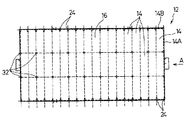
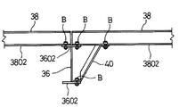
図1は実施の形態に係る工場の土間コンクリート部分の概略平面図、図2は図1のA矢視概略図、図3は土間コンクリートや鉄骨柱、支柱、大梁部分の斜視図、図4は基礎梁部分の断面図、図5はブレースと鉄骨柱の連結部分の正面図、図6は支柱と下部大梁の連結部分の正面図、図7は鉄骨柱と下部大梁の連結部分の正面図、図8は下部大梁と上部大梁の連結部分の正面図、図9は上部大梁と小梁の連結部分の正面図を示す。
工場12は平屋建物で高さよりも大きな平面寸法を有しており、工場12の形状は、平面視した場合に矩形で、この矩形は、同一形状の多数の仮想の長方形14がそれらの長辺14Aと短辺14Bを合致させて並べられることで形成されている。
本実施の形態に係る躯体骨組み構造は、土間コンクリート16、基礎梁18、鉄骨柱24、支柱32、下部大梁34、上部大梁36、小梁38などで構成されている。
【0007】
前記土間コンクリート16は、工場12の床を構成するもので、工場12の平面視形状とほぼ等しい矩形に形成されている。
図4に示すように、前記基礎梁18は、その高さが地表面GLよりも上方に突出され、基礎梁18の上面と土間コンクリート16の上面とは面一に形成され、基礎梁18は土間コンクリート16の一部を構成している。なお、図4において符号20は増し打ち箇所を示し、符号22は砕石層を示している。
【0008】
前記鉄骨柱24は前記土間コンクリート16の外縁で、かつ、前記仮想の長方形14の短辺14B(桁行方向)に沿って、前記仮想の長方形14の各角部毎に立設されている。前記鉄骨柱24はH形鋼からなり、各鉄骨柱24は設計寸法で定められた均一の長さに形成されている。
図5に示すように、隣り合う鉄骨柱24の上下部は、十字状になるように2本づつ斜め掛け渡された合計4本のブレース26により連結されている。ブレース26の鉄骨柱24への連結は、2本のブレース26の両端にそれぞれ溶着されたガセットプレート28が、鉄骨柱24のフランジ2402に高力ボルトBで締結することでなされている。
前記各ブレース28はターンバックル30を含んで構成され、ターンバックル30によりブレース28の緊締、弛緩の調節が簡単に行なわれるように構成されている。
【0009】
前記支柱32は前記土間コンクリート16の外縁の内側で前記仮想の長方形14の各角部毎に、本実施の形態では、2つの仮想の長方形14を合わせた矩形の各角部毎に立設されると共に、土間コンクリート16の外縁で、かつ、前記仮想の長方形14の長辺14A(梁間方向)に沿って前記仮想の長方形14の各角部毎に立設されている。
前記支柱32は角形鋼管からなり、各支柱32は設計寸法で定められた均一の長さに形成されている。
そして、仮想の長方形14の長辺14A方向に間隔をおき仮想の長方形14の短辺14B方向に延在させた2本の下部大梁(桁行大梁)34が各支柱32の上端に載置されて固定されている。本実施の形態では下部大梁34として複数のH形鋼が連結して用いられ、H形鋼の連結は、下部大梁34に作用する応力がゼロの箇所において、それらのウェブ同士に添え板を当て高力ボルトで締結することでなされている。
また、上部大梁36の外端に位置する(土間コンクリート16の外縁に位置する)鉄骨柱24により水平応力を負担し、下部大梁34の両端の間に位置する支柱32により鉛直力のみを負担するように構成している。すなわち、下部大梁34の両端の間に位置する支柱32と下部大梁34の連結は、図6に示すように、支柱32の上端に水平に設けられたトッププレート3202の上に、下部大梁34の下フランジ3402が載せられ、トッププレート3202とフランジ3402が高力ボルトBで着脱可能に締結されることでなされ、図6において符号3410は、下部大梁34に固定された補強プレートを示す。
【0010】
前記鉄骨柱24の上端と下部大梁34の上に、前記仮想の長方形14の短辺方向に間隔をおき長辺14A方向に延在させた複数の上部大梁(梁間大梁)36が載置され固定され、上部大梁36は、図2に示すように、梁間方向の中央部が高くなるように配設されている。
より詳細に説明すると、鉄骨柱24の上端と上部大梁36との連結は、図7に示すように、鉄骨柱24の上端に設けられたトッププレート2402の上に、上部大梁36の下フランジ3602が載せられ、トッププレート2402とフランジ3602が高力ボルトBで着脱可能に締結されることでなされ、図7において符号3610は、上部大梁36に固定された補強プレートを示す。
また、下部大梁34と上部大梁36との連結は、図8に示すように、下部大梁34の上フランジ3402の上に、上部大梁36の下フランジ3602が載せられ、双方のフランジ3402,3602が高力ボルトBで着脱可能に締結されることでなされている。
【0011】
前記小梁38は複数の上部大梁36の上に、前記仮想の長方形14の短辺14B方向に延在させて複数載置され固定されている。
より詳細に説明すると、小梁38としてH形鋼が用いられ、小梁38の長さは長方形14の短辺14Bの2倍の寸法を有し、小梁38の中間部と両端が各上部大梁36上に連結された所謂2連梁である。
小梁38の両端と上部大梁36の連結は、図9に示すように、上部大梁36の上フランジ3602の上に小梁38の下フランジ3802を載せ、双方のフランジ3602,3802が高力ボルトBで着脱可能に締結されることでなされ、隣り合う小梁36の端部の間には隙間が確保される。また、下部大梁36の座屈を防止するため、構造簡易なアングル材40が上部大梁36の下フランジ3602と小梁38の下フランジ3802間に掛け渡される。
なお、小梁38の中間部と上部大梁36の連結も、上部大梁36の上フランジ3602の上に小梁38の下フランジ3802を載せ、双方のフランジ3602,3802が高力ボルトBで着脱可能に締結されることでなされる。
そして、図3に示すように、水平方向に延在させた複数の胴縁42が上下に間隔をおいて各鉄骨柱24に連結され、これら複数の胴縁42に外壁44が取着され、また、小梁38に屋根46が取着される。
【0012】
本実施の形態によれば、同一形状の多数の仮想の長方形14がそれらの長辺14Aと短辺14Bを合致させて並べられることで、需要者の要望、仕様に対応した形状で、かつ、鉄骨柱24や支柱32の位置、数を含めた工場の設計が簡単になされる。
また、基礎梁18を地表面GLよりも上方に突出させ、土間コンクリート16の一部を構成させるようにしたので、土の掘削深さを減少させることで土工事の軽減化を図れ、また、基礎梁18と土間コンクリート16の双方に同時にコンクリートを打設することができるようになるので、工数を減少すると共に、捨てコンを不要にでき、コストを削減する上で有利となる。
【0013】
また、隣り合う鉄骨柱24の相互間を、両端にガセットプレート28が溶着された2本のブレース26を用いて連結するようにしたので、鉄骨柱24の構造を複雑化することなく簡単に補強でき、コストを削減する上で有利となる。
また、上部大梁36の外端に位置する鉄骨柱24により水平応力を負担し、下部大梁34の両端の間に位置する支柱32により鉛直力のみを負担するように構成したので、支柱32として断面が非常に小さい鉄骨を用いることができ、したがって、建物の内部スペースを広く取る上で有利となる。また、支柱32は、水平応力を負担しないサポート柱であるため、支柱32を水平方向に自由に移動でき、工場の機器を配置する上で極めて有利となる。
【0014】
また、上部大梁36を配設するに際して、上部大梁36と鉄骨柱24の連結を、鉄骨柱24のトッププレート2402の上に上部大梁36の下フランジ3602を載せ、トッププレート2402とフランジ3602を高力ボルトBで締結することで行なうようにしたので、従来のように、柱からブラケットを張り出し、このブラケットと、上部大梁の上下のフランジとウェブとに添え板を合わせ、高力ボルト摩擦接合する場合に比べ、使用する鉄骨量を削減し、施工を簡単化する上で極めて有利となる。
また、上部大梁36を配設するに際して、上部大梁36と下部大梁34の連結を、下部大梁34の上フランジ3402の上に上部大梁36の下フランジ3602を載せ、双方のフランジ3402,3602が高力ボルトBで締結することで行なうようにしたので、従来のようにガセットプレートや添え板を省き、施工を簡単化できる。また、上部大梁36が連結梁となるため、その断面を小さくでき、さらに、上部大梁36を屋根勾配を付ける部材としても兼用できるので、使用する鉄骨量を削減する上でも有利となる。
【0015】
また、小梁38を複数の上部大梁36の上に配設するに際して、小梁38と上部大梁36の連結を、上部大梁36の上フランジ3602の上に小梁38の下フランジ3802を載せ、双方のフランジ3602,3802を高力ボルトBで締結することで行なうようにしたので、従来のようにガセットプレートや添え板を省き、施工を簡単化できる。また、本実施の形態では、小梁38を2連梁としたので、小梁38の断面を小さくでき使用する鉄骨量を削減する上で有利となる。
【0016】
なお、本実施の形態では、平屋建ての工場に適用した場合について説明したが、本発明は倉庫などのようなその他の平面寸法が高さよりも大きい建物の躯体骨組みに適用可能であり、また、2階建て以上の建物にも無論適用される。
【0017】
【発明の効果】
以上の説明で明らかなように本発明によれば、設計、施工の簡易化を図れ、コストダウンおよび工期の短縮化を達成できる建物の躯体骨組み構造が得られる。
【図面の簡単な説明】
【図1】実施の形態に係る工場の土間コンクリート部分の概略平面図である。
【図2】図1のA矢視概略図である。
【図3】土間コンクリートや鉄骨柱、支柱、大梁部分の斜視図である。
【図4】基礎梁部分の断面図である。
【図5】ブレースと鉄骨柱の連結部分の正面図である。
【図6】支柱と下部大梁の連結部分の正面図である。
【図7】鉄骨柱と下部大梁の連結部分の正面図である。
【図8】下部大梁と上部大梁の連結部分の正面図である。
【図9】上部大梁と小梁の連結部分の正面図である。
【符号の説明】
12 工場
14 仮想の長方形
16 土間コンクリート
18 基礎梁
24 鉄骨柱
32 支柱
34 下部大梁
36 上部大梁
38 小梁[0001]
BACKGROUND OF THE INVENTION
The present invention relates to a frame structure of a building such as a factory or a warehouse in which a planar dimension is larger than a height.
[0002]
[Prior art]
Conventionally, in buildings such as factories and warehouses where the plane dimension is larger than the height, the actual situation is that the design and construction are performed each time according to the demands and specifications of the consumers.
[0003]
[Problems to be solved by the invention]
Therefore, there are limits to reducing costs and shortening the construction period.
The present invention has been devised in view of the above circumstances, and an object of the present invention is to provide a building frame structure that can simplify design and construction, and can achieve cost reduction and shortening of a construction period. It is in.
[0004]
[Means for Solving the Problems]
In order to achieve the above object, the present invention provides a framework structure of a building having a planar dimension larger than a height such as a factory or a warehouse, and the shape of the building is a large number of the same shape when viewed in plan. Virtual rectangles are formed by aligning their long sides and short sides, and the soil concrete constituting the floor of the building is formed in a shape substantially equal to the plan view shape of the building. The foundation beam has a height protruding above the ground surface and constitutes a part of the soil concrete, and a number of steel columns of uniform length are the outer edges of the soil concrete, and the virtual beam A plurality of uniform-length struts are provided for each corner of the virtual rectangle inside the outer edge of the soil concrete along the short side of the rectangle. Align virtual rectangles It is erected at each corner of the rectangle, and is erected at each corner of the virtual rectangle at the outer edge of the soil concrete and along the long side of the virtual rectangle. A plurality of lower girder extending in the short side direction is placed and fixed on the upper end of each column, and a plurality of upper girder extending in the long side direction of the virtual rectangle is connected to the upper end of the steel column and the A plurality of small beams placed and fixed on the lower large beam and extending in the short side direction of the virtual rectangle are placed and fixed on the plurality of upper large beams. And
[0005]
ADVANTAGE OF THE INVENTION According to this invention, the design of a building including the position and number of a steel pillar and a support | pillar is also made simply, and it is a shape corresponding to a consumer's request and specification.
In addition, construction of soil concrete, steel columns, columns, lower beams, upper beams and beams can be simplified, which is advantageous in reducing the amount of steel.
[0006]
DETAILED DESCRIPTION OF THE INVENTION
Hereinafter, an embodiment in which the frame structure of the present invention is applied to a factory will be described with reference to the accompanying drawings.
1 is a schematic plan view of a soil concrete part of a factory according to an embodiment, FIG. 2 is a schematic view taken along arrow A in FIG. 1, FIG. 3 is a perspective view of soil concrete, a steel column, a column, and a large beam part. FIG. 5 is a front view of the connection portion between the brace and the steel column, FIG. 6 is a front view of the connection portion between the support column and the lower beam, and FIG. 7 is a front view of the connection portion between the steel column and the lower beam. FIG. 8 is a front view of a connecting portion between the lower and upper large beams, and FIG. 9 is a front view of a connecting portion between the upper and lower beams.
The
The frame structure according to the present embodiment includes the
[0007]
The
As shown in FIG. 4, the height of the
[0008]
The
As shown in FIG. 5, the upper and lower portions of
Each
[0009]
The
The
Then, two lower large beams (girder large beams) 34 which are spaced in the direction of the
Further, horizontal stress is borne by the
[0010]
A plurality of upper girder beams (interbeam girder beams) 36 extending in the
More specifically, as shown in FIG. 7, the upper end of the
Further, as shown in FIG. 8, the lower
[0011]
A plurality of the
More specifically, an H-shaped steel is used as the
As shown in FIG. 9, the
In addition, the middle part of the
Then, as shown in FIG. 3, a plurality of trunk edges 42 extending in the horizontal direction are connected to each
[0012]
According to the present embodiment, a large number of
In addition, since the
[0013]
Further, since the
Further, since the
[0014]
Further, when the
Further, when the
[0015]
When arranging the
[0016]
In the present embodiment, the case where the present invention is applied to a one-storied factory has been described, but the present invention is applicable to a building frame of a building whose other planar dimensions are larger than the height, such as a warehouse, Of course, this applies to buildings with two or more floors.
[0017]
【The invention's effect】
As is apparent from the above description, according to the present invention, it is possible to simplify the design and construction, and to obtain a building framework structure that can achieve cost reduction and shortening of the construction period.
[Brief description of the drawings]
FIG. 1 is a schematic plan view of a soil concrete part of a factory according to an embodiment.
FIG. 2 is a schematic view taken along arrow A in FIG.
FIG. 3 is a perspective view of soil concrete, a steel column, a column, and a large beam portion.
FIG. 4 is a cross-sectional view of a foundation beam portion.
FIG. 5 is a front view of a connecting portion between a brace and a steel column.
FIG. 6 is a front view of a connecting portion between a column and a lower beam.
FIG. 7 is a front view of a connecting portion between a steel column and a lower beam.
FIG. 8 is a front view of a connecting portion between a lower beam and an upper beam.
FIG. 9 is a front view of a connecting portion between an upper beam and a beam.
[Explanation of symbols]
12
Claims (3)
前記建物の形状は、平面視した場合に、同一形状の多数の仮想の長方形がそれらの長辺と短辺を合致させて並べられることで形成され、
前記建物の床を構成する土間コンクリートは、前記建物の平面視形状とほぼ等しい形状に形成され、
前記建物の基礎梁は、その高さが地表面よりも上方に突出され、前記土間コンクリートの一部を構成しており、
多数の均一長さの鉄骨柱が、土間コンクリートの外縁で、かつ、前記仮想の長方形の短辺に沿って前記仮想の長方形の各角部毎に立設され、
多数の均一長さの支柱が土間コンクリートの外縁の内側で前記仮想の長方形の各角部毎に、あるいは、複数の仮想の長方形を合わせた矩形の各角部毎に立設されると共に、土間コンクリートの外縁で、かつ、前記仮想の長方形の長辺に沿って前記仮想の長方形の各角部毎に立設され、
前記仮想の長方形の短辺方向に延在させた複数の下部大梁が各支柱の上端に載置されて固定され、
前記仮想の長方形の長辺方向に延在させた複数の上部大梁が前記鉄骨柱の上端と前記下部大梁の上に載置されて固定され、
前記仮想の長方形の短辺方向に延在させた複数の小梁が、前記複数の上部大梁の上に載置されて固定されている、
ことを特徴とする建物の躯体骨組み構造。It is a framework structure of buildings such as factories and warehouses where the plane dimensions are larger than the height,
The shape of the building is formed by arranging a large number of virtual rectangles of the same shape with their long sides and short sides aligned when viewed in plan,
The soil concrete constituting the floor of the building is formed in a shape substantially equal to the shape of the building in plan view,
The foundation beam of the building has a height protruding above the ground surface and constitutes a part of the soil concrete,
A number of steel columns of uniform length are erected on the outer edge of the concrete between the concrete and along the short sides of the virtual rectangle for each corner of the virtual rectangle,
A large number of uniform-length struts are erected at each corner of the virtual rectangle inside the outer edge of the soil concrete, or at each corner of the rectangle including a plurality of virtual rectangles. At the outer edge of the concrete and along each of the corners of the virtual rectangle along the long side of the virtual rectangle,
A plurality of lower girder extending in the short side direction of the virtual rectangle is placed and fixed on the upper end of each column,
A plurality of upper girder extending in the long side direction of the virtual rectangle is placed and fixed on the upper end of the steel column and the lower girder,
A plurality of small beams extending in the short side direction of the virtual rectangle are placed and fixed on the plurality of upper large beams,
The frame structure of a building characterized by that.
Priority Applications (1)
| Application Number | Priority Date | Filing Date | Title |
|---|---|---|---|
| JP2000114992A JP4386308B2 (en) | 2000-04-17 | 2000-04-17 | Building frame structure |
Applications Claiming Priority (1)
| Application Number | Priority Date | Filing Date | Title |
|---|---|---|---|
| JP2000114992A JP4386308B2 (en) | 2000-04-17 | 2000-04-17 | Building frame structure |
Publications (2)
| Publication Number | Publication Date |
|---|---|
| JP2001295378A JP2001295378A (en) | 2001-10-26 |
| JP4386308B2 true JP4386308B2 (en) | 2009-12-16 |
Family
ID=18626710
Family Applications (1)
| Application Number | Title | Priority Date | Filing Date |
|---|---|---|---|
| JP2000114992A Expired - Fee Related JP4386308B2 (en) | 2000-04-17 | 2000-04-17 | Building frame structure |
Country Status (1)
| Country | Link |
|---|---|
| JP (1) | JP4386308B2 (en) |
Families Citing this family (4)
| Publication number | Priority date | Publication date | Assignee | Title |
|---|---|---|---|---|
| JP6473768B2 (en) * | 2017-02-16 | 2019-02-20 | ジェイアール東海静岡開発株式会社 | Underpass building structure |
| JP7580207B2 (en) * | 2020-05-26 | 2024-11-11 | 株式会社竹中工務店 | Column and beam structure |
| CN113638317B (en) * | 2021-06-25 | 2022-11-01 | 中铁五局集团成都工程有限责任公司 | Method for integrally forming and hoisting cover beam steel reinforcement framework on ground |
| JP7665211B2 (en) * | 2022-12-21 | 2025-04-21 | 株式会社田中構造設計 | Beam-column joint structure |
-
2000
- 2000-04-17 JP JP2000114992A patent/JP4386308B2/en not_active Expired - Fee Related
Also Published As
| Publication number | Publication date |
|---|---|
| JP2001295378A (en) | 2001-10-26 |
Similar Documents
| Publication | Publication Date | Title |
|---|---|---|
| CA2017669C (en) | Curtain wall for a building | |
| JP5316490B2 (en) | Steel sheet pile underground wall structure | |
| WO2011136350A1 (en) | Planar support frame and solar power generation device | |
| KR102522487B1 (en) | Prefabricated steel frame seismic reinforcement structure by slab joint H-beam bracing | |
| JP2001295378A (en) | Building frame structure | |
| JP2690868B2 (en) | Building steel foundation | |
| JP2979117B2 (en) | Building foundation method | |
| JP2000027291A (en) | Steel building structure | |
| JP2577973B2 (en) | How to build a building with a basement | |
| JP3055431U (en) | Composite pillars for steel structures | |
| JP5475054B2 (en) | Seismic shelter reinforcement method and seismic shelter with high seismic strength | |
| JP2001164658A (en) | Beam joint structure and unit building | |
| JP3043938B2 (en) | Joint structure between reinforced concrete columns and steel beams | |
| JP7851098B2 (en) | Structures and construction methods for structures | |
| JPH0358617B2 (en) | ||
| JP3721508B2 (en) | building | |
| JP5759857B2 (en) | Platform structure | |
| JP3520483B2 (en) | Reinforcement structure of existing building | |
| JPH084007A (en) | Joint foundation for temporary shutter | |
| JP2021188273A (en) | Column-beam frame | |
| JP2026003816A (en) | Method of constructing column-beam frame | |
| JP2540369B2 (en) | How to build a building with a basement | |
| JP2894217B2 (en) | Building structural frame | |
| JP2992581B2 (en) | Ramen construction method of steel building | |
| JP2026003814A (en) | Method of constructing column-beam frame |
Legal Events
| Date | Code | Title | Description |
|---|---|---|---|
| A621 | Written request for application examination |
Free format text: JAPANESE INTERMEDIATE CODE: A621 Effective date: 20070404 |
|
| A977 | Report on retrieval |
Free format text: JAPANESE INTERMEDIATE CODE: A971007 Effective date: 20081212 |
|
| TRDD | Decision of grant or rejection written | ||
| A01 | Written decision to grant a patent or to grant a registration (utility model) |
Free format text: JAPANESE INTERMEDIATE CODE: A01 Effective date: 20090924 |
|
| A01 | Written decision to grant a patent or to grant a registration (utility model) |
Free format text: JAPANESE INTERMEDIATE CODE: A01 |
|
| A61 | First payment of annual fees (during grant procedure) |
Free format text: JAPANESE INTERMEDIATE CODE: A61 Effective date: 20090925 |
|
| R150 | Certificate of patent or registration of utility model |
Free format text: JAPANESE INTERMEDIATE CODE: R150 Ref document number: 4386308 Country of ref document: JP Free format text: JAPANESE INTERMEDIATE CODE: R150 |
|
| FPAY | Renewal fee payment (event date is renewal date of database) |
Free format text: PAYMENT UNTIL: 20121009 Year of fee payment: 3 |
|
| FPAY | Renewal fee payment (event date is renewal date of database) |
Free format text: PAYMENT UNTIL: 20131009 Year of fee payment: 4 |
|
| R250 | Receipt of annual fees |
Free format text: JAPANESE INTERMEDIATE CODE: R250 |
|
| R250 | Receipt of annual fees |
Free format text: JAPANESE INTERMEDIATE CODE: R250 |
|
| R250 | Receipt of annual fees |
Free format text: JAPANESE INTERMEDIATE CODE: R250 |
|
| R250 | Receipt of annual fees |
Free format text: JAPANESE INTERMEDIATE CODE: R250 |
|
| S531 | Written request for registration of change of domicile |
Free format text: JAPANESE INTERMEDIATE CODE: R313531 |
|
| R350 | Written notification of registration of transfer |
Free format text: JAPANESE INTERMEDIATE CODE: R350 |
|
| R250 | Receipt of annual fees |
Free format text: JAPANESE INTERMEDIATE CODE: R250 |
|
| R250 | Receipt of annual fees |
Free format text: JAPANESE INTERMEDIATE CODE: R250 |
|
| R250 | Receipt of annual fees |
Free format text: JAPANESE INTERMEDIATE CODE: R250 |
|
| LAPS | Cancellation because of no payment of annual fees |