JP4384978B2 - Annuloplasty ring of mitral valve with posterior curvature - Google Patents
Annuloplasty ring of mitral valve with posterior curvature Download PDFInfo
- Publication number
- JP4384978B2 JP4384978B2 JP2004519963A JP2004519963A JP4384978B2 JP 4384978 B2 JP4384978 B2 JP 4384978B2 JP 2004519963 A JP2004519963 A JP 2004519963A JP 2004519963 A JP2004519963 A JP 2004519963A JP 4384978 B2 JP4384978 B2 JP 4384978B2
- Authority
- JP
- Japan
- Prior art keywords
- ring
- ring body
- annuloplasty
- axis
- posterior
- Prior art date
- Legal status (The legal status is an assumption and is not a legal conclusion. Google has not performed a legal analysis and makes no representation as to the accuracy of the status listed.)
- Expired - Lifetime
Links
Images


Classifications
-
- A—HUMAN NECESSITIES
- A61—MEDICAL OR VETERINARY SCIENCE; HYGIENE
- A61F—FILTERS IMPLANTABLE INTO BLOOD VESSELS; PROSTHESES; DEVICES PROVIDING PATENCY TO, OR PREVENTING COLLAPSING OF, TUBULAR STRUCTURES OF THE BODY, e.g. STENTS; ORTHOPAEDIC, NURSING OR CONTRACEPTIVE DEVICES; FOMENTATION; TREATMENT OR PROTECTION OF EYES OR EARS; BANDAGES, DRESSINGS OR ABSORBENT PADS; FIRST-AID KITS
- A61F2/00—Filters implantable into blood vessels; Prostheses, i.e. artificial substitutes or replacements for parts of the body; Appliances for connecting them with the body; Devices providing patency to, or preventing collapsing of, tubular structures of the body, e.g. stents
- A61F2/02—Prostheses implantable into the body
- A61F2/24—Heart valves ; Vascular valves, e.g. venous valves; Heart implants, e.g. passive devices for improving the function of the native valve or the heart muscle; Transmyocardial revascularisation [TMR] devices; Valves implantable in the body
- A61F2/2442—Annuloplasty rings or inserts for correcting the valve shape; Implants for improving the function of a native heart valve
- A61F2/2445—Annuloplasty rings in direct contact with the valve annulus
- A61F2/2448—D-shaped rings
-
- A—HUMAN NECESSITIES
- A61—MEDICAL OR VETERINARY SCIENCE; HYGIENE
- A61F—FILTERS IMPLANTABLE INTO BLOOD VESSELS; PROSTHESES; DEVICES PROVIDING PATENCY TO, OR PREVENTING COLLAPSING OF, TUBULAR STRUCTURES OF THE BODY, e.g. STENTS; ORTHOPAEDIC, NURSING OR CONTRACEPTIVE DEVICES; FOMENTATION; TREATMENT OR PROTECTION OF EYES OR EARS; BANDAGES, DRESSINGS OR ABSORBENT PADS; FIRST-AID KITS
- A61F2250/00—Special features of prostheses classified in groups A61F2/00 - A61F2/26 or A61F2/82 or A61F9/00 or A61F11/00 or subgroups thereof
- A61F2250/0014—Special features of prostheses classified in groups A61F2/00 - A61F2/26 or A61F2/82 or A61F9/00 or A61F11/00 or subgroups thereof having different values of a given property or geometrical feature, e.g. mechanical property or material property, at different locations within the same prosthesis
- A61F2250/0018—Special features of prostheses classified in groups A61F2/00 - A61F2/26 or A61F2/82 or A61F9/00 or A61F11/00 or subgroups thereof having different values of a given property or geometrical feature, e.g. mechanical property or material property, at different locations within the same prosthesis differing in elasticity, stiffness or compressibility
Abstract
Description
本発明は、一般に医療用デバイスに関し、詳しくは、環状成形リング、および患者の心臓の僧帽弁環を外科的に再構成するための関連した治療に関する。より詳しくは、本発明は、前部局面の下で低下した後部局面を有する機能的な僧帽弁逆流によって遭遇した病理学の異常な環に適合する、僧帽弁修復デバイスおよび対応する技術に関する。 The present invention relates generally to medical devices, and more particularly to an annular shaped ring and related treatments for surgically reconfiguring a mitral valve annulus of a patient's heart. More particularly, the present invention relates to a mitral valve repair device and corresponding technique that fits an abnormal annulus of pathology encountered by functional mitral regurgitation with a posterior aspect lowered under the anterior aspect. .
ヒト心臓の解剖において、左心房は、肺静脈を通して肺から酸素を含んだ血液を受け入れる。僧帽弁は、左心房を左心室から切り離す。心拡張期の間、収縮が心房を通して洞房結節発展によって起こるので、酸素に富んだ血液は僧帽弁を通過して左心室に流れる。この局面において、上行大動脈に通じる大動脈弁は閉じ、それによって左心室が血液で満ちる。類似した静脈血の流れが、肺動脈弁を右心房から右心室まで生じる。一旦心室が満たされると、それらは心収縮期の間収縮して、心臓から血液を追い出す。心収縮期の間、僧帽弁は閉じ、そして大動脈弁は開く。このようにして、血液が左心房に逆流して血液を大動脈に、そして、そこから体の全体に送られることを防ぐ。心収縮期の間、左心室と関連した圧力は高いので、血液がシステムを通って逆流することを防ぐための僧帽弁の適切な機能は、極めて重要である。 In human heart dissection, the left atrium receives oxygenated blood from the lungs through the pulmonary veins. The mitral valve separates the left atrium from the left ventricle. During diastole, contraction occurs through the atria by sinoatrial node development, so oxygen-rich blood flows through the mitral valve to the left ventricle. In this aspect, the aortic valve leading to the ascending aorta is closed, thereby filling the left ventricle with blood. Similar venous blood flow occurs from the right atrium to the right ventricle through the pulmonary valve. Once the ventricles are filled, they contract during systole and expel blood from the heart. During systole, the mitral valve closes and the aortic valve opens. In this way, blood is prevented from flowing back into the left atrium and flowing into the aorta and from there to the entire body. Since the pressure associated with the left ventricle is high during systole, proper functioning of the mitral valve to prevent blood from flowing back through the system is extremely important.
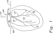
左心室LVおよび僧帽弁MVのさまざまな解剖学的構成要素が、前後平面に沿った垂直断面に示すように、図Iにおいて表される。僧帽弁の環MAは、左心房LAおよび左心室LV間のオリフィスを囲む繊維状リングを備えている。平均的な人の僧帽弁環の断面積は、5〜11cm2である。僧帽弁環MAの前部局面は、「心臓の骨格」の一部を形成し、左および右の繊維状の三角、LTおよびRTを含む。図3は、手術の間に露出された、左心房から僧帽弁を示す。僧帽弁は、前小葉ALと協同する後小葉PLを有する二先弁である。左の三角LTおよび右の三角RTは、前小葉ALおよび後小葉PLの接合位置で示される。これらの接合位置は、また、小葉間の横連合として公知である。僧帽弁環MAの後部局面は、前部局面とは対照的に、主に心臓の外壁の筋肉組織からなっている。 Various anatomical components of the left ventricle LV and the mitral valve MV are represented in FIG. I as shown in a vertical section along the anteroposterior plane. The mitral valve annulus MA comprises a fibrous ring that surrounds the orifice between the left atrium LA and the left ventricle LV. The average human mitral annulus cross-sectional area is 5-11 cm 2 . The anterior aspect of the mitral annulus MA forms part of the “cardiac skeleton” and includes left and right fibrous triangles, LT and RT. FIG. 3 shows the mitral valve from the left atrium exposed during surgery. The mitral valve is a two-way valve with a posterior lobule PL that cooperates with the anterior lobule AL. The left triangle LT and the right triangle RT are shown at the junction position of the anterior leaflet AL and the posterior leaflet PL. These junction locations are also known as lateral associations between leaflets. The posterior aspect of the mitral annulus MA, in contrast to the anterior aspect, mainly consists of the musculature of the outer wall of the heart.
再び図1を参照して、一対の小突起状筋P1およびP2は、左心室LVの内部壁の底部に付着している。腱索CTは、小突起状筋P1およびP2、および前小葉および後部小葉ALおよびPLの自由端の間を伸びて連結する。腱索は、外観上はひも様であり、時々「心臓ストリング」と呼ばれている。図示されないが、腱索CTは、各々の小突起状筋P1およびP2と、両方の小葉の間を伸びる。小突起状筋P1およびP2の収縮は、腱索CTを引く。そして、それは次々に小葉を開くように引き、そして筋肉が弛緩したときに、腱索がゆるくなり小葉が一緒に又は「接合」するようになる。図1に示されるように、左心室LVの方へ相互に曲がった小葉の自由縁部を有し、通常機能している心臓における実質的な表面領域に沿って、小葉は接合する。 Referring to FIG. 1 again, the pair of small protrusion muscles P1 and P2 are attached to the bottom of the inner wall of the left ventricle LV. The chord CT extends and connects between the microprojection-like muscles P1 and P2 and the free ends of the anterior and posterior lobules AL and PL. The chords are string-like in appearance and are sometimes called “heart strings”. Although not shown, the chord CT extends between each microprojection muscle P1 and P2 and both leaflets. Contraction of microprojection muscles P1 and P2 pulls chord CT. It then pulls to open the leaflets one after another, and when the muscles relax, the chords loosen and the leaflets come together or “join”. As shown in FIG. 1, the leaflets join along a substantial surface area in the normally functioning heart, with the free edges of the leaflets bent to each other toward the left ventricle LV.
図1に示すように、そして、説明の目的のために、普通に健康な心臓の僧帽弁の環MAは、一般に、僧帽弁MVを介した平均的血流方向22に対して垂直に規定される基準平面20にある。典型的な僧帽弁の環MAは三次元でもよいが、基準平面20は、環の後部および前部で後部側の相対的位置を代表する。
As shown in FIG. 1 and for purposes of illustration, a normally healthy heart mitral valve annulus MA is generally perpendicular to the average
多くの先進諸国において、うっ血性心不全は入院および死の主要な原因であり、そして、その発生率は増加している。僧帽弁における知覚低下により、血液が後方へ左心房(第2の僧帽弁逆流として公知)に流れ込むときには、左心室は体の全体にわたって血液を循環させるよう、かなり激しく送らなければならず、それは次第にうっ血性心不全を促進する。心臓移植は、選択された高度のうっ血性心不全および末期心疾患患者の標準の治療と考えられる。しかし、少数の移植用提供心臓だけは利用でき、そして、より弱い患者にはかなり手術の危険がある。したがって、代替の医療戦略および外科的戦略が、そのような状況を治療するために進歩している。 In many developed countries, congestive heart failure is a major cause of hospitalization and death, and its incidence is increasing. When blood flows backwards into the left atrium (known as second mitral regurgitation) due to reduced perception in the mitral valve, the left ventricle must be sent fairly vigorously to circulate blood throughout the body, It gradually promotes congestive heart failure. Heart transplantation is considered the standard treatment for selected patients with severe congestive heart failure and end-stage heart disease. However, only a few donor donor hearts are available and there is a significant surgical risk for weaker patients. Accordingly, alternative medical and surgical strategies are progressing to treat such situations.
僧帽弁逆流の1つの典型的な原因は、環のより可撓性な後部局面に沿った僧帽弁の環MAの奇形である。図2に示すように、一部の患者は、左心室LVの拡大によって生じる環の後部局面の低下hを経験する。左心室LVの拡大は、イオパチック(iopathic)な拡張型心筋症または虚血性の心筋症患者の僧帽弁逆流に伴う症状、および他の病因(例えば、粘液マットの多い疾患、心内膜炎、先天性欠損またはリウマチ性弁膜疾患)からの長期の弁口逆流患者の症状である。上記から見られるように、図3はこの後部局面低下から後部および前部小葉ALおよびPL間の接合の二次の損失を例示する。 One typical cause of mitral regurgitation is a malformation of the mitral annulus MA along the more flexible posterior aspect of the annulus. As shown in FIG. 2, some patients experience a decrease h in the posterior aspect of the annulus caused by enlargement of the left ventricle LV. The enlargement of left ventricular LV is associated with symptoms associated with mitral regurgitation in patients with iopathic dilated cardiomyopathy or ischemic cardiomyopathy, and other etiologies (eg, diseases with high mucus mats, endocarditis, Symptoms of patients with long-term valve reflux from congenital defects or rheumatic valvular disease. As seen from above, FIG. 3 illustrates the secondary loss of the junction between the posterior and anterior leaflets AL and PL from this posterior aspect decline.
図2に示すように、左心室LVの拡大は、一般に小突起状筋P1およびP2、および僧帽弁の環MAの間の距離を増やす。これは、次々に腱索CTの緊張を増やす。索で増加した緊張と結合する距離hだけ基準平面20の下の環の後部局面の垂下または低下は、心収縮期の間一緒にくるために小葉の能力を減らす。
As shown in FIG. 2, enlargement of the left ventricle LV generally increases the distance between the microprojection muscles P1 and P2 and the mitral valve annulus MA. This in turn increases the tension of the chord CT. The drooping or lowering of the posterior aspect of the annulus below the
さまざまな介入が、逆流性のオリフィス面積のサイズを変えるために用いられてきた。
環状形成リングは、長年にわたって、弁の機能を減少する僧帽弁逆流および他の状況を修正するために、さまざまな形状および構成において開発されてきた。例えば、カルペンティエル(Carpentier)らは、米国特許第4,055,861号において、その一つは閉じ(またはD形の)、他のものは開いている(またはC形の)心臓弁のための二つ半剛性支持体を開示する。閉構成において、リングは、通常、前後部平面について対称で、凸面後側部およびほぼ真っ直ぐな前側部を有する。米国特許第5,104,407号、5,201,880および5,607,471は、全て、それらの前側部にわずかに上方へ曲げられた閉環状形成リングを開示する。僧帽弁の環MAの前部局面が繊維状で、従って、比較的柔軟性がない(少なくとも後部局面と比較して)ので、各々のリングの前側部の上方へのカーブはより密接にそのリングを僧帽弁の環の解剖学的輪郭に従わせ、そして、そのことが環の過度の変形を減らしている。
Various interventions have been used to change the size of the reflux orifice area.
Annuloplasty rings have been developed in various shapes and configurations over the years to modify mitral regurgitation and other situations that reduce valve function. For example, Carpentier et al. In US Pat. No. 4,055,861, one of which is closed (or D-shaped) and the other is open (or C-shaped). Two semi-rigid supports are disclosed. In the closed configuration, the ring is typically symmetrical about the front and rear planes and has a convex rear side and a substantially straight front side. U.S. Pat. Nos. 5,104,407, 5,201,880 and 5,607,471 all disclose closed annuloplasty rings bent slightly upward on their front sides. Since the anterior aspect of the mitral annulus MA is fibrous and therefore relatively inflexible (at least compared to the posterior aspect), the upward curve on the anterior side of each ring is more closely related to that The ring conforms to the anatomical contour of the mitral valve annulus, which reduces excessive deformation of the annulus.
一般に、従来の環状形成リングは、僧帽弁の環MAの原物の構成を復元することを目的とするか、換言すれば、図1に示すように、基準平面20へできるだけ近くに環を持ってくる。図2に示すように、状態を修正するとき、リングが上方へ環を「引く」ので、高いストレスが、環状形成リングを環の後部局面に接続している縫合においてつくられる。縫合が組織を刺し通すので、ストレスはしばしばこの場所で、環からリングの裂開または分離を引き起こす。 In general, conventional annuloplasty rings are intended to restore the original configuration of the mitral valve annulus MA, or in other words, as shown in FIG. bring up. As shown in FIG. 2, when the condition is corrected, high stress is created in the suture connecting the annuloplasty ring to the back aspect of the ring because the ring “pulls” upwards. Stress often causes tearing or separation of the ring from the ring at this location as the suture pierces the tissue.
大動脈の環の修正が、従って、僧帽弁の環を有する非常に異なるリングを必要とする点に、ここで注意されなければならない。例えば、米国特許第5.258,021および6,231,602は、3つの尖端大動脈の環の上下する形状に続く、洞様毛細血管(sinusoidal)の又はいわゆる「波形模様に切られた」環状形成リングを開示する。そのようなリングは、僧帽弁欠乏を修復することに適していない。 It should be noted here that the modification of the aortic ring therefore requires a very different ring with a mitral valve annulus. For example, US Pat. Nos. 5,258,021 and 6,231,602 describe sinusoidal or so-called “corrugated” annulus following the up and down shape of the three apical aortic rings. A forming ring is disclosed. Such a ring is not suitable for repairing mitral valve deficiency.
うっ血性心不全および僧帽弁逆流の処置の良好な結果が、上記の方法および装置の予備使用において得られた一方、これらの結果が大幅に改善され得ると思われる。具体的には、従来のリングの移植を伴うストレスを減らすことができる僧帽弁の環状形成リングを製造することは望ましい。 While good results for the treatment of congestive heart failure and mitral regurgitation have been obtained in the preliminary use of the above methods and devices, it appears that these results can be greatly improved. Specifically, it is desirable to produce an annuloplasty ring of a mitral valve that can reduce the stress associated with conventional ring implantation.
(発明の要旨)
本発明は、その後部局面が異常に下方へ垂下するように、病的状態がある僧帽弁環の移植のために環状形成リングを提供する。環状形成リングは、前部セクションおよび後部セクションを有する丸いリング体を含む。リング体は、上方への方向および下方への方向(僧帽弁環を通した血流の方向に対応する下方への方向)を規定する中心流れ軸について配向される。リング体の後部セクションは、中心流れ軸と直交する平面から下方へ曲がる。
(Summary of the Invention)
The present invention provides an annuloplasty ring for the implantation of a mitral annulus with a pathological condition such that the posterior aspect droops down abnormally. The annular forming ring includes a round ring body having a front section and a rear section. The ring body is oriented about a central flow axis that defines an upward direction and a downward direction (a downward direction corresponding to the direction of blood flow through the mitral valve annulus). The rear section of the ring body bends downward from a plane perpendicular to the central flow axis.
リング体は、それの一端から最下位点まで約2〜15mmの間で下方へ曲がることができ、望ましくは、その一端から最下位点まで約4〜8mmの間で下方へ曲がることができる。リング体の湾曲は、後部セクションに集中でき、またはしなくてもよい。好ましくは、リング体の湾曲が手動で再形成できるように、リング体は展性の材料でできている。望ましく、リング体は、各鼓動サイクルの全体にわたって心臓の筋肉によって与えられるストレスに対抗して、その後部湾曲を保持する半硬質材料で形成されている。リング体は後部セクションにおいて以外は実質的に平坦であってもよく、又は、リング体の前部セクションはその一端から最下位点まで上方へ湾曲し得る。 The ring body can bend down between about 2 to 15 mm from one end thereof to the lowest point, and desirably bend down between about 4 to 8 mm from its one end to the lowest point. The curvature of the ring body may or may not be concentrated on the rear section. Preferably, the ring body is made of a malleable material so that the curvature of the ring body can be manually reshaped. Desirably, the ring body is formed of a semi-rigid material that retains its posterior curvature against the stress imposed by the heart muscle throughout each beating cycle. The ring body may be substantially flat except in the rear section, or the front section of the ring body may curve upward from one end to the lowest point.
平面図で、流れ軸に沿って見られるように、リング体は好ましくは短軸に対して直交する長軸を有する卵円形状を規定し、短軸が前部および後部セクションを二分する。さらに、後部セクションの湾曲は、約0〜45°の角度θ(より好ましくは約30°)によってリング体の回りに長軸から間隔を置いて配置される短軸を横切る対称の場所から始まることができる。 In plan view, as seen along the flow axis, the ring body preferably defines an oval shape with a major axis perpendicular to the minor axis, the minor axis bisecting the front and rear sections. Furthermore, the curvature of the rear section begins at a symmetrical location across the minor axis spaced from the major axis about the ring body by an angle θ of about 0-45 ° (more preferably about 30 °). Can do.
リング体は、後部セクション上の下方への湾曲の両側に、二つ上方への湾曲を更に含むことができる。そして、ここにおいて、下方への湾曲は約2〜15mmであり得る。実施例において、リング体は、同心で配置される複数のリング要素を含む。各リング要素の間にポリマーストリップを提供し得る。任意に、リング要素は、流れ軸に直交する寸法の高さより流れ軸寸法の高さが実質的にかなり高いバンドを有する。さらに、リング要素は、リング体が、リング体の剰余周辺より後部セクションで多く曲がるように、様々な高さを有し得る。 The ring body may further include two upward curvatures on either side of the downward curvature on the rear section. And here, the downward curve may be about 2-15 mm. In an embodiment, the ring body includes a plurality of ring elements arranged concentrically. A polymer strip may be provided between each ring element. Optionally, the ring element has a band whose flow axis dimension is substantially higher than the dimension perpendicular to the flow axis. Furthermore, the ring elements can have various heights so that the ring body bends more in the rear section than around the remainder of the ring body.
本発明の別の態様は、前部局面に関連して、血流軸に沿って下方へ低下させる後部局面を有する僧帽の心臓弁環を修復する方法である。該方法は、環の前部局面を嵌合するために大きさが設定された前部セクションおよび後部局面に大きさが設定された後部セクションを有する環状形成リングを移植することを含む。ここにおいて、リング後部セクションは、前部セクションと関連して中心軸と平行に下方へ曲がる。該環状形成リングは展性であり得、よって外科医は手で後部セクションの曲げを調整する。 Another aspect of the invention is a method of repairing a mitral heart valve annulus having a posterior aspect that is lowered downwardly along the blood flow axis relative to the anterior aspect. The method includes implanting an annuloplasty ring having a front section sized to fit the front aspect of the annulus and a rear section sized to the rear aspect. Here, the ring rear section bends downward parallel to the central axis in relation to the front section. The annuloplasty ring can be malleable, so the surgeon manually adjusts the bending of the rear section.
本発明の他の態様は、後部局面、前部局面および血流軸を有する僧帽の心臓弁環を修復する方法である。該方法は、僧帽弁の環の形状を検査すること、および僧帽弁の環の形状に基づいて三次元環状形成リングを選択すること、を含む。該選択された環状形成リングは、通常、中心軸周辺に配置される前部セクションおよび後部セクションを有する。該中心軸は、上方への方向と下方への方向とを規定し、そこで、リング後部セクションは、中心軸に対して直交する平面から下方へ曲がる。該方法は、リング後部セクションを僧帽弁環の後部局面に取り付け、そして後部セクションが血流方向へ曲がるように、環状形成リングを移植することを含む。 Another aspect of the invention is a method of repairing a mitral heart valve annulus having a posterior aspect, an anterior aspect and a blood flow axis. The method includes examining the shape of the mitral valve annulus and selecting a three-dimensional annuloplasty ring based on the mitral valve annulus shape. The selected annular forming ring typically has a front section and a rear section disposed about the central axis. The central axis defines an upward direction and a downward direction, where the ring rear section bends downward from a plane perpendicular to the central axis. The method includes attaching the posterior ring section to the posterior aspect of the mitral valve annulus and implanting the annuloplasty ring such that the posterior section bends in the direction of blood flow.
(好ましい実施形態の説明)
添付の図は、本発明の環状形成リングのいくつかの例示的な実施形態を例示する。それらは、それは連続して、前側部、後側部および左右の側を有すると記載され得る。側部の全ては、それらの間で突然の移行を示すために、特別な境界なしで、ほぼ曲線形である。むしろ、隣接した側部間のなめらかな移行セクションは、リングにほぼ丸い(例えば、卵形の)形状を与える曲線の接続を提供する。
(Description of Preferred Embodiment)
The accompanying figures illustrate several exemplary embodiments of the annular forming ring of the present invention. They can be described as having a front side, a back side and left and right sides in succession. All of the sides are generally curvilinear, with no special boundaries, to show a sudden transition between them. Rather, the smooth transition section between adjacent sides provides a curvilinear connection that gives the ring a substantially round (eg, oval) shape.
本発明の具体的な環状形成リング30は、図4に示され、僧帽弁の環MA周辺に移植される。上述の通り、僧帽弁の環は、前部小葉ALおよび後部小葉PLを有する。リング30が移植されるとき、小葉は、接合表面32で接触するように、一緒に閉じおよび支持される。該リング30は、このように機能的な僧帽弁逆流の問題を修正する。
A
リング30は、カーブする後部セクション36の反対側に、比較的まっすぐな前部セクション34を有する卵円か又はややD形の外形を有する。一対の三角または,横連合標識38a、38bは、一般に前部側34の限界を定め、一方、一対の対向する側部セクション40a、40bは、これらの各標識および後部セクション36の間を伸びる。複数の結ばれた縫合糸ループ42はリング30を僧帽弁の環MAに固定するために典型的に用いられる。但し、ステープル、フィブリン接着剤等のような他の締着具が用いられ得る。
The
環状形成リング30が適している病的状態において、図2に図示するように、僧帽弁の環の後部局面は、前部局面に対して下げられる。図4の見るところでは、後部局面は、前部局面に対してページと下げられる。本発明の環状形成リング30は、僧帽弁の環MAの改質形状にほぼ従うよう形成された後部セクション36を有する。換言すれば、後部セクション36は、前部セクション34に対してページと曲げられる。例えば、縫合42を有する場所に固定されるとき、リング30は、最初の実質的に平面構成へ環が転じようとすることよりむしろ、その改質形状に僧帽弁の環MAを支持する。同時に、リング30は、望ましくは、前部小葉ALおよび後部小葉PLを互いに近づけるように、環によって規定されるオリフィス円周を締めつける。リング30は、僧帽弁の環MAの後部局面をその改質位置から上方へ引かないので、高いストレスが取付け縫合42において生じることはなく、よって、潜在的な裂開がより少ない。
In pathological conditions where an
図5および図6は、その後側部に押し下げられた僧帽弁の環より上に、斜視で具体的な環状形成リング30を例示する。その後部セクション36のリング30の湾曲(bow)は、図6に最も良く示されるが、機能的な僧帽弁逆流によって遭遇した病理学の僧帽弁の環MAの後部局面の低下を模倣している。
FIGS. 5 and 6 illustrate a
図4〜6の具体的な環状形成リング30は、図7A〜7Cにより詳細に示される。該リング30は、繊維状カバーを有して完全に示されている。オリエンテーションの目的のために、図7Aは、X軸およびY軸が、図1および図2に関して上記したようにほぼ基準平面20を規定する直交軸を例示する。X軸は、最大寸法の点で、一方側40aから反対側40bへリング30を横切って伸びる。よって、X軸は、リング30の長軸を規定する。Y軸は、後部セクション36の中間まで前側部34の中間の間で伸びているリング30のための対称面を規定する。Y軸も、リング30の短軸を規定する。
The
多くの従来のリングと同様に、長軸寸法に対する短軸寸法の比率は、望ましくは約3:4である。この大きさの比率は、僧帽弁の環の「クラシック」形状であって、環状形成リング30の最高の構成であり得る。しかしながら、より小さい長軸に対する短軸の比率を有する他の形状が、実際には小葉接合を増加し得ることは考察される。幾何学的に正確でないにもかかわらず、非円形状リング構成は、卵形、楕円又はD形が考慮され得る。本発明は、また、例えば、C−形状を有する不連続なリングの形をとることができる点に留意すべきである。そのようなリングの中断は前部セクションにおいてあってもよく、後部セクションは連続し、説明されるように下方への湾曲を示す。
As with many conventional rings, the ratio of the minor axis dimension to the major axis dimension is desirably about 3: 4. This size ratio is the “classic” shape of the mitral valve annulus and may be the best configuration of the
移植されるときに、図7BのZ軸はリング30を通した血流の軸に沿った状態にある。そして、陽のZ方向が「上方への」方向であり、負のZ方向が「下方への」方向であり、そして、血液が下方への方向へ流れるように、リング30が僧帽弁環に移植されるように設計されることが理解される。
When implanted, the Z-axis of FIG. 7B is along the axis of blood flow through the
数ポイントは、後部湾曲を記載するのを助けるために、リング30周辺で強調(note)される。これらの位置および図8A〜8Bに示されるものは、リング30の横断面を通る想像上の中心点である。2つのポイントAは、X軸から角距離θでY軸の両側に対称的に位置が決められる。後部セクション36の中間点は、Bと示されている。位置BがZ軸に沿って最も低い所にあるように、リング30は後部ボウ(bow)を備えている。図7Cで、この後部の湾曲の大きさは、寸法Z1によって示される。後部セクション36の両側の位置Aは、後部の湾曲が開始する位置を表す。すなわち、後部セクションを除いて、リング30は、好ましくは実質的に平坦である。しかしながら、従来技術の特定のリングにおいてのように、前部セクション34は、約2〜4mm(0.08〜0.16インチ)間の距離だけ上方へ任意に曲げられ得る。後の実施例において、後部セクション36は、三角標識38a、38bの立面に関して、Z方向に下方へ湾曲する。
A few points are highlighted around the
僧帽弁の環の全体のサイズ、後部局面の解剖学的垂下の範囲および外科医の好みを含むさまざまな他の要因によって決定される範囲の間を変化する寸法Zおよび角度θによって、図7A〜7Cに示すように、リング30のための様々な可能な構成が考察される。それにもかかわらず、本明細書に記載されるように、特定の解剖学的不規則を示す大多数の患者を支持し、かつ修正するのに、特定の範囲が適していると考えられる。下方への湾曲または後部湾曲は、位置A間の大多数の後部セクション36に沿って好ましくは伸びる。その位置は、X軸(θ)から0と45°の間にある。より好ましくは、位置Aは、20〜40°の間、さらに好ましくはX軸から約30°である。リングの寸法に従い、湾曲Z1の大きさが、約2〜15mm(0.08〜0.59インチ)の間にあり得、より典型的には、約4〜8mm(0.16〜0.31インチ)の間である。
With dimensions Z and angle θ varying between the overall size of the mitral valve annulus, the anatomical droop range of the posterior aspect and the range determined by various other factors, including surgeon preference, FIG. Various possible configurations for the
Y−軸について対象のようにリング30が図7A〜7Cに示されているが、必ずしもそうである必要があるというわけではない。例えば、下方への湾曲が後部セクション36に集中していないように、位置BはY軸から移されることができる。非対称のリングは、図9Aおよび図9Bに関して図示および記載される。
Although the
図8A〜8Cは、上方および下方への湾曲を有する本発明の別の環状形成リング50を例示する。また、リング50は、繊維状カバーを有して全体が示されている。該リング50は、前部セクション52、後部セクション54、およびそれらの間の一対の側部セクション(番号なし)を含む。リング50は、前部セクション52でほぼ平らで、後部セクション54で形がつけられている。Y軸を横切って対称的に配置されたポイントAは、再び、リング50が平面からカーブし始める両側の位置を意味する。本実施形態において、図8に最も良く示されるように、リングは位置Aから高い位置Cまで、Z軸方向に上方へカーブする。次に、後部セクション54の中間点Bまで下方へもぐる。位置AおよびB間のリングの下方への湾曲は、寸法Z2として図8Cに示される。それは、図7Cで、Z1のために与えられたのと類似した大きさを有する。上方へのカーブは、患者の環形状によくマッチするように選択し得る。さらに、前部セクション52は、約2〜4mm(0.08〜0.16インチ)の間の距離だけ、上方へ曲げることができる。
8A-8C illustrate another
図8A〜8Cに示されるリング50のさまざまな交換は、多数の要因に基づいて変えられる寸法について考察される。ある具体例では、位置Aは、望ましくはX軸から角距離αに配置され約0〜15°の間であり、より望ましくは約5〜10°の間である。リング50の最大高さの位置Cは、好ましくはX軸から角距離βの間隔を置いて配置され、約15〜45°の間、より好ましくは、約25〜35°の間である。図7A〜7Cの実施形態においてのように、リング50の最下位点Bは、Z軸に沿って曲げられることができ、その結果、示された図8Cのように、リングの寸法に従い、Z2は望ましくは約2〜15mm(0.08〜0.59インチ)の間であり、さらに典型的には、約4〜8mm(0.16〜0.31インチ)の間である。従って、リング50の総高さは、少なくとも2mmであって、15mmより大きくてもよい。
Various exchanges of the
図9Aおよび図9Bは、本発明の環状形成リングで使用のための、内側リング体60を示す。該リング体60は、後部セクション64の中央からオフセットした後部湾曲62を有する。図示の実施例では、湾曲62は、リング体60の全ての長軸幅の約20%だけ、後部中央側(右に)の方へオフセットされる。オフセットを述べる他の方法は、平面図で、湾曲62が時計位置に集中しているということである(12:00が前側部に集中している)。その意味において、湾曲62が3:00および6:00の間に集中し、より好ましく5:00に中心がある。軸の湾曲Z3が示され、約2.0mm(0.08インチ)から約4.0mm(0.16インチ)、より好ましくは、約3.0mm(0.12インチ)から約3.8mm(0.15インチ)まで、リングサイズに基づいて変化させることができる。加えて、リング体60は、約2〜4mm(0.08〜0.16インチ)間の距離だけ上方へ曲げられる前部セクション66を有する。
9A and 9B show an
内側リング体60は、正中切開から移される後部環の湾曲を有する患者にかなう非対称のリングを示す。大部分の患者が本明細書において記載の異常な状況から生じたそのような奇形の解剖を有すると思われている。しかしながら、中央に置かれるかまたは左にオフセットされる後部湾曲が観察された。従って、本発明で具体化されるリングの1つの構成は、中央の後部湾曲または右に後部湾曲を有して予備形成されたものである。そして、それは展性があるので、患者の環の正確な形状の検査の後に、湾曲が外科医によって大きくされ、または小さくされ得る。さらに、この種の可変リングでは湾曲は、例えば、右から左へ移すことさえできる。リングの材料によって手で変形可能であるが、一旦移植され、通常の生理学的ストレスを受けたときに、更なる変形に耐えるよう充分に硬質である。
リングは、好ましくは内側リング体と、リング体が僧帽弁の環内に縫合される外部縫合鞘とを有する。その縫合鞘は、充分に多孔質でありおよび/または可撓性を有し、そこを通して縫合可能である。一つの具体的な構成は、管状の鞘(例えば、シリコーンなどの縫合透過材料からなる)内に、内部リング体を囲み、それは、例えばポリエチルテレフタレートなどの繊維状チューブで覆われる。 The ring preferably has an inner ring body and an external suture sheath in which the ring body is sewn into the annulus of the mitral valve. The suture sheath is sufficiently porous and / or flexible and can be sutured therethrough. One specific configuration encloses an inner ring body within a tubular sheath (eg, made of a suture permeable material such as silicone), which is covered with a fibrous tube such as polyethyl terephthalate.
単に僧帽弁の環の円周を減らすように設計されている可撓性環状形成リングとは反対に、本発明の環状形成リングは半硬式でなければならない。それは、各鼓動サイクルの全体にわたって心臓の筋肉によって与えられるストレスに対抗して、その後部湾曲を保持しなければならない。例えば、リング体は、例えばElgiloy(コバルトニッケル合金)、チタンまたはニチノール(ニッケルチタン合金)のような材料から作ることができる。 As opposed to a flexible annuloplasty ring that is designed to simply reduce the circumference of the mitral valve annulus, the annuloplasty ring of the present invention must be semi-rigid. It must retain its posterior curvature against the stress exerted by the heart muscle throughout each beating cycle. For example, the ring can be made of a material such as Elgiloy (cobalt nickel alloy), titanium or nitinol (nickel titanium alloy).
図10は、多数の平坦なエルジロイ(Elgiloy)のバンドを、複合構造で利用する本発明の環状形成リングの内側本体の一つの具体的な構造を例示する。詳しくは、4つのバンド70a、70b、70cおよび70dが外側から内部まである。4つのバンドは、リングの形状に同心で配置されている。各々のバンドは、約1.4〜2.0mm(0.056〜0.078インチ)の間の幅を有する材料からなる平坦なストリップである。一実施例において、バンド70がリング体の前部セクション72において重なり、複数の位置で例えば、スポット溶接などにより、一緒に固定されている。各ストリップの幅は、また後部セクション74において前部セクション72においてより大きくてもよく、そこは、リング体が他のいかなるセクションにおいてより、後部セクションでより可撓性であることを意味する。図示はしていないが、保護膜の複数のストリップが、各々のバンド70間に、および外側バンド70a.の外表面に使われる。該ストリップは、ポリマー(例えばマイラー)であり得る。ストリップは、バンド70間の磨耗を減らし、更に縫合針を外側バンド70aから偏らせて、そのことがそこにスクラッチすることを防止するのを助ける。
FIG. 10 illustrates one specific structure of the inner body of the annuloplasty ring of the present invention that utilizes multiple flat Elgiloy bands in a composite structure. Specifically, there are four
現在の環状形成リングを有する僧帽弁環の支持が、後小葉が前小葉の下に押し下げられることを維持し、よって健康な弁膜においてよりそれらの間の接合の領域が異なることは、また容易に明らかである。これは、小突起状筋および後小葉が置き換えられた心室の病理学に必要とされる。しかしながら、当業者は、接合が利用できる小葉のサープラス(surplus)領域のため、および、再編成が他の変化で、かなりの時間2つの小葉の接合を改良し、従って逆流を減少させる環の形状にオフセットするので、小葉のこのわずかな再編成が受け入れられることを認識する。 Supporting the mitral annulus with the current annuloplasty ring also keeps the posterior leaflet pressed down below the anterior leaflet, so it is also easier to have a different area of junction between them than in a healthy leaflet Is obvious. This is required for the pathology of the ventricle where the microprojection and posterior lobule have been replaced. However, those of ordinary skill in the art will appreciate the shape of the annulus that improves the joining of two leaflets for a significant amount of time, thus reducing regurgitation, due to the surplus region of the leaflets available for joining and reorganization with other changes. Recognize that this slight reorganization of the leaflets is acceptable.
関連する技術の当業者は、さまざまな変更態様または変化が、本発明の意図された精神および範囲から逸脱することなく、この仮出願に記載されている本発明の実施例および実施形態になされることができると認識する。この点に関して、本明細書に記載されている本発明の具体例は、本出願に開示されるより広い発明の概念の実施例として理解されるべきである。 Those skilled in the relevant art will appreciate that various modifications or changes may be made to the examples and embodiments of the invention described in this provisional application without departing from the intended spirit and scope of the invention. Recognize that you can. In this regard, the embodiments of the invention described herein are to be understood as examples of the broader inventive concept disclosed in this application.
Claims (16)
該僧帽弁環の前部局面上に移植されるように適合された前部セクション(34、52、66、72)および該僧帽弁環の後部局面上に移植されるように適合された後部セクション(36、54、64、74)を有する丸いリング体(60)を有し;
ここで、該リング体(60)は中心流れ軸の周りに配向され、該流れ軸は、上方への方向および下方への方向を規定し、該下方への方向は該僧帽弁環を通る血流の方向に対応し、ここで、該流れ軸に沿って観察される平面図において、該リング体(60)が短軸と直交する長軸を備えたほぼ卵形状を規定し、該短軸が該前部セクションおよび該後部セクションの両方を二分し;
該後部セクション(36、54、64、74)において、該リング体(60)は中心流れ軸と直交する平面から下方へ曲がり、そして該下方への曲がり(62)が該短軸から離れて該後部セクションに中心があり、そして隣接するリング体セクションへの滑らかな曲線遷移を示すことを特徴とする、環状形成リング。An annuloplasty ring (30 , 50) for implantation of a mitral valve annulus,
Anterior section (34, 52, 66, 72) adapted to be implanted on the anterior aspect of the mitral valve annulus and adapted to be implanted on the posterior aspect of the mitral annulus Having a round ring body (60) with rear sections (36, 54, 64, 74) ;
Here, the ring body (60) is oriented around a central flow axis that defines an upward direction and a downward direction, the downward direction passing through the mitral valve annulus. Corresponding to the direction of blood flow, where, in a plan view observed along the flow axis, the ring body (60) defines an approximately egg shape with a major axis orthogonal to the minor axis, An axis bisects both the front section and the rear section;
In the rear section (36,54,64,74), said ring member (60) Ri songs from a plane perpendicular to the center flow axis downwards, and bending of the said lower (62) is separated from the short axis An annular forming ring characterized in that it is centered in the rear section and exhibits a smooth curvilinear transition to an adjacent ring body section .
Applications Claiming Priority (2)
| Application Number | Priority Date | Filing Date | Title |
|---|---|---|---|
| US10/192,516 US6858039B2 (en) | 2002-07-08 | 2002-07-08 | Mitral valve annuloplasty ring having a posterior bow |
| PCT/US2003/021208 WO2004004607A1 (en) | 2002-07-08 | 2003-07-03 | Mitral valve annuloplasty ring having a posterior bow |
Publications (3)
| Publication Number | Publication Date |
|---|---|
| JP2005532119A JP2005532119A (en) | 2005-10-27 |
| JP2005532119A5 JP2005532119A5 (en) | 2006-08-17 |
| JP4384978B2 true JP4384978B2 (en) | 2009-12-16 |
Family
ID=30000029
Family Applications (1)
| Application Number | Title | Priority Date | Filing Date |
|---|---|---|---|
| JP2004519963A Expired - Lifetime JP4384978B2 (en) | 2002-07-08 | 2003-07-03 | Annuloplasty ring of mitral valve with posterior curvature |
Country Status (9)
| Country | Link |
|---|---|
| US (1) | US6858039B2 (en) |
| EP (1) | EP1519695B1 (en) |
| JP (1) | JP4384978B2 (en) |
| AT (1) | ATE339934T1 (en) |
| AU (1) | AU2003248833B2 (en) |
| BR (1) | BR0312502B1 (en) |
| CA (1) | CA2489368C (en) |
| DE (1) | DE60308523T2 (en) |
| WO (1) | WO2004004607A1 (en) |
Families Citing this family (240)
| Publication number | Priority date | Publication date | Assignee | Title |
|---|---|---|---|---|
| US6406420B1 (en) * | 1997-01-02 | 2002-06-18 | Myocor, Inc. | Methods and devices for improving cardiac function in hearts |
| FR2768324B1 (en) | 1997-09-12 | 1999-12-10 | Jacques Seguin | SURGICAL INSTRUMENT FOR PERCUTANEOUSLY FIXING TWO AREAS OF SOFT TISSUE, NORMALLY MUTUALLY REMOTE, TO ONE ANOTHER |
| US6332893B1 (en) * | 1997-12-17 | 2001-12-25 | Myocor, Inc. | Valve to myocardium tension members device and method |
| US6736845B2 (en) * | 1999-01-26 | 2004-05-18 | Edwards Lifesciences Corporation | Holder for flexible heart valve |
| US6752813B2 (en) | 1999-04-09 | 2004-06-22 | Evalve, Inc. | Methods and devices for capturing and fixing leaflets in valve repair |
| US10327743B2 (en) | 1999-04-09 | 2019-06-25 | Evalve, Inc. | Device and methods for endoscopic annuloplasty |
| CA2620783C (en) | 1999-04-09 | 2011-04-05 | Evalve, Inc. | Methods and apparatus for cardiac valve repair |
| US7226467B2 (en) | 1999-04-09 | 2007-06-05 | Evalve, Inc. | Fixation device delivery catheter, systems and methods of use |
| US6440164B1 (en) * | 1999-10-21 | 2002-08-27 | Scimed Life Systems, Inc. | Implantable prosthetic valve |
| US7507252B2 (en) * | 2000-01-31 | 2009-03-24 | Edwards Lifesciences Ag | Adjustable transluminal annuloplasty system |
| US6537198B1 (en) * | 2000-03-21 | 2003-03-25 | Myocor, Inc. | Splint assembly for improving cardiac function in hearts, and method for implanting the splint assembly |
| US7510572B2 (en) * | 2000-09-12 | 2009-03-31 | Shlomo Gabbay | Implantation system for delivery of a heart valve prosthesis |
| US6723038B1 (en) * | 2000-10-06 | 2004-04-20 | Myocor, Inc. | Methods and devices for improving mitral valve function |
| US6616684B1 (en) * | 2000-10-06 | 2003-09-09 | Myocor, Inc. | Endovascular splinting devices and methods |
| US6602286B1 (en) | 2000-10-26 | 2003-08-05 | Ernst Peter Strecker | Implantable valve system |
| US6955689B2 (en) * | 2001-03-15 | 2005-10-18 | Medtronic, Inc. | Annuloplasty band and method |
| US6786924B2 (en) * | 2001-03-15 | 2004-09-07 | Medtronic, Inc. | Annuloplasty band and method |
| US7935145B2 (en) * | 2001-05-17 | 2011-05-03 | Edwards Lifesciences Corporation | Annuloplasty ring for ischemic mitral valve insuffuciency |
| ITMI20011012A1 (en) * | 2001-05-17 | 2002-11-17 | Ottavio Alfieri | ANNULAR PROSTHESIS FOR MITRAL VALVE |
| US6908482B2 (en) | 2001-08-28 | 2005-06-21 | Edwards Lifesciences Corporation | Three-dimensional annuloplasty ring and template |
| US7367991B2 (en) * | 2001-08-28 | 2008-05-06 | Edwards Lifesciences Corporation | Conformal tricuspid annuloplasty ring and template |
| US20080154359A1 (en) * | 2001-11-01 | 2008-06-26 | Salgo Ivan S | Non-planar cardiac vascular support prosthesis |
| US6805710B2 (en) * | 2001-11-13 | 2004-10-19 | Edwards Lifesciences Corporation | Mitral valve annuloplasty ring for molding left ventricle geometry |
| US6575971B2 (en) | 2001-11-15 | 2003-06-10 | Quantum Cor, Inc. | Cardiac valve leaflet stapler device and methods thereof |
| US6764510B2 (en) | 2002-01-09 | 2004-07-20 | Myocor, Inc. | Devices and methods for heart valve treatment |
| US7118595B2 (en) * | 2002-03-18 | 2006-10-10 | Medtronic, Inc. | Flexible annuloplasty prosthesis and holder |
| US6719786B2 (en) * | 2002-03-18 | 2004-04-13 | Medtronic, Inc. | Flexible annuloplasty prosthesis and holder |
| US6752828B2 (en) | 2002-04-03 | 2004-06-22 | Scimed Life Systems, Inc. | Artificial valve |
| US7007698B2 (en) * | 2002-04-03 | 2006-03-07 | Boston Scientific Corporation | Body lumen closure |
| US20030233022A1 (en) * | 2002-06-12 | 2003-12-18 | Vidlund Robert M. | Devices and methods for heart valve treatment |
| US7608103B2 (en) * | 2002-07-08 | 2009-10-27 | Edwards Lifesciences Corporation | Mitral valve annuloplasty ring having a posterior bow |
| EP1553897A1 (en) * | 2002-10-24 | 2005-07-20 | Boston Scientific Limited | Venous valve apparatus and method |
| US7247134B2 (en) * | 2002-11-12 | 2007-07-24 | Myocor, Inc. | Devices and methods for heart valve treatment |
| US7112219B2 (en) * | 2002-11-12 | 2006-09-26 | Myocor, Inc. | Devices and methods for heart valve treatment |
| US6945957B2 (en) * | 2002-12-30 | 2005-09-20 | Scimed Life Systems, Inc. | Valve treatment catheter and methods |
| DE10301023A1 (en) * | 2003-01-13 | 2004-07-22 | Medos Medizintechnik Ag | Implant, in particular ring for heart valve, designed in curved and asymmetric shape |
| KR100466839B1 (en) * | 2003-03-28 | 2005-01-17 | 주식회사 사이언씨티 | Aortic valve Repairing Apparatus Sets and Treatment Method Using The Same |
| US10646229B2 (en) | 2003-05-19 | 2020-05-12 | Evalve, Inc. | Fixation devices, systems and methods for engaging tissue |
| US8128681B2 (en) * | 2003-12-19 | 2012-03-06 | Boston Scientific Scimed, Inc. | Venous valve apparatus, system, and method |
| US7854761B2 (en) * | 2003-12-19 | 2010-12-21 | Boston Scientific Scimed, Inc. | Methods for venous valve replacement with a catheter |
| US7871435B2 (en) * | 2004-01-23 | 2011-01-18 | Edwards Lifesciences Corporation | Anatomically approximate prosthetic mitral heart valve |
| EP1943982A1 (en) * | 2004-02-23 | 2008-07-16 | International Heart Institute of Montana Foundation | Papilloplasty band and sizing device |
| US8206439B2 (en) * | 2004-02-23 | 2012-06-26 | International Heart Institute Of Montana Foundation | Internal prosthesis for reconstruction of cardiac geometry |
| JP4975609B2 (en) * | 2004-02-27 | 2012-07-11 | エーオーテックス, インコーポレイテッド | Prosthetic heart valve delivery system and method |
| US20090132035A1 (en) * | 2004-02-27 | 2009-05-21 | Roth Alex T | Prosthetic Heart Valves, Support Structures and Systems and Methods for Implanting the Same |
| US20070073387A1 (en) * | 2004-02-27 | 2007-03-29 | Forster David C | Prosthetic Heart Valves, Support Structures And Systems And Methods For Implanting The Same |
| US7951196B2 (en) | 2004-04-29 | 2011-05-31 | Edwards Lifesciences Corporation | Annuloplasty ring for mitral valve prolapse |
| US7294148B2 (en) | 2004-04-29 | 2007-11-13 | Edwards Lifesciences Corporation | Annuloplasty ring for mitral valve prolapse |
| US7452376B2 (en) * | 2004-05-14 | 2008-11-18 | St. Jude Medical, Inc. | Flexible, non-planar annuloplasty rings |
| EP1761211B1 (en) * | 2004-05-14 | 2013-08-28 | St. Jude Medical, Inc. | Apparatus for holding and supporting an annuloplasty ring |
| US7938856B2 (en) * | 2004-05-14 | 2011-05-10 | St. Jude Medical, Inc. | Heart valve annuloplasty prosthesis sewing cuffs and methods of making same |
| US20050278022A1 (en) * | 2004-06-14 | 2005-12-15 | St. Jude Medical, Inc. | Annuloplasty prostheses with improved anchoring structures, and related methods |
| EP1913900A1 (en) * | 2004-06-29 | 2008-04-23 | SIEVERS, Hans-Hinrich, Dr. | Implant with a ring-shaped base plate |
| US7758638B2 (en) * | 2004-07-13 | 2010-07-20 | Ats Medical, Inc. | Implant with an annular base |
| US7566343B2 (en) | 2004-09-02 | 2009-07-28 | Boston Scientific Scimed, Inc. | Cardiac valve, system, and method |
| CA2748617C (en) | 2004-09-27 | 2014-09-23 | Evalve, Inc. | Methods and devices for tissue grasping and assessment |
| US8052592B2 (en) | 2005-09-27 | 2011-11-08 | Evalve, Inc. | Methods and devices for tissue grasping and assessment |
| BRPI0404380C1 (en) * | 2004-10-14 | 2008-07-15 | Malavazi Vedacoes Ind Ltda | housed mechanical seal enhancements for progressive cavity pumps |
| US7854755B2 (en) * | 2005-02-01 | 2010-12-21 | Boston Scientific Scimed, Inc. | Vascular catheter, system, and method |
| US20060173490A1 (en) * | 2005-02-01 | 2006-08-03 | Boston Scientific Scimed, Inc. | Filter system and method |
| US7878966B2 (en) | 2005-02-04 | 2011-02-01 | Boston Scientific Scimed, Inc. | Ventricular assist and support device |
| US7780722B2 (en) | 2005-02-07 | 2010-08-24 | Boston Scientific Scimed, Inc. | Venous valve apparatus, system, and method |
| US7670368B2 (en) * | 2005-02-07 | 2010-03-02 | Boston Scientific Scimed, Inc. | Venous valve apparatus, system, and method |
| US8470028B2 (en) | 2005-02-07 | 2013-06-25 | Evalve, Inc. | Methods, systems and devices for cardiac valve repair |
| EP3967269A3 (en) | 2005-02-07 | 2022-07-13 | Evalve, Inc. | Systems and devices for cardiac valve repair |
| US7867274B2 (en) * | 2005-02-23 | 2011-01-11 | Boston Scientific Scimed, Inc. | Valve apparatus, system and method |
| US8608797B2 (en) | 2005-03-17 | 2013-12-17 | Valtech Cardio Ltd. | Mitral valve treatment techniques |
| US7842085B2 (en) * | 2005-03-23 | 2010-11-30 | Vaso Adzich | Annuloplasty ring and holder combination |
| US7575595B2 (en) | 2005-03-23 | 2009-08-18 | Edwards Lifesciences Corporation | Annuloplasty ring and holder combination |
| US7722666B2 (en) | 2005-04-15 | 2010-05-25 | Boston Scientific Scimed, Inc. | Valve apparatus, system and method |
| US20060247491A1 (en) * | 2005-04-27 | 2006-11-02 | Vidlund Robert M | Devices and methods for heart valve treatment |
| US8012198B2 (en) | 2005-06-10 | 2011-09-06 | Boston Scientific Scimed, Inc. | Venous valve, system, and method |
| US8685083B2 (en) * | 2005-06-27 | 2014-04-01 | Edwards Lifesciences Corporation | Apparatus, system, and method for treatment of posterior leaflet prolapse |
| EP1898840A1 (en) * | 2005-06-27 | 2008-03-19 | The Cleveland Clinic Foundation | Apparatus for placement in the annulus of a tricuspid valve |
| US8951285B2 (en) | 2005-07-05 | 2015-02-10 | Mitralign, Inc. | Tissue anchor, anchoring system and methods of using the same |
| US7776084B2 (en) * | 2005-07-13 | 2010-08-17 | Edwards Lifesciences Corporation | Prosthetic mitral heart valve having a contoured sewing ring |
| US7455689B2 (en) * | 2005-08-25 | 2008-11-25 | Edwards Lifesciences Corporation | Four-leaflet stented mitral heart valve |
| US7569071B2 (en) * | 2005-09-21 | 2009-08-04 | Boston Scientific Scimed, Inc. | Venous valve, system, and method with sinus pocket |
| US8007530B2 (en) * | 2005-09-30 | 2011-08-30 | Medtronic, Inc. | Tool and method for implanting an annuloplasty prosthesis |
| US9011528B2 (en) * | 2005-09-30 | 2015-04-21 | Medtronic, Inc. | Flexible annuloplasty prosthesis |
| JP4820875B2 (en) * | 2005-10-26 | 2011-11-24 | セント ジュード メディカル インコーポレイテッド | Saddle-shaped mitral annuloplasty prosthesis with asymmetry and related methods |
| US8764820B2 (en) | 2005-11-16 | 2014-07-01 | Edwards Lifesciences Corporation | Transapical heart valve delivery system and method |
| WO2007100410A2 (en) | 2005-12-15 | 2007-09-07 | Georgia Tech Research Corporation | Systems and methods for enabling heart valve replacement |
| CA2669195C (en) | 2005-12-15 | 2013-06-25 | Georgia Tech Research Corporation | Systems and methods to control the dimension of a heart valve |
| WO2007100408A2 (en) | 2005-12-15 | 2007-09-07 | Georgia Tech Research Corporation | Papillary muscle position control devices, systems & methods |
| US7799038B2 (en) * | 2006-01-20 | 2010-09-21 | Boston Scientific Scimed, Inc. | Translumenal apparatus, system, and method |
| US7749266B2 (en) * | 2006-02-27 | 2010-07-06 | Aortx, Inc. | Methods and devices for delivery of prosthetic heart valves and other prosthetics |
| US8147541B2 (en) * | 2006-02-27 | 2012-04-03 | Aortx, Inc. | Methods and devices for delivery of prosthetic heart valves and other prosthetics |
| DE602007012691D1 (en) | 2006-05-15 | 2011-04-07 | Edwards Lifesciences Ag | SYSTEM FOR CHANGING THE GEOMETRY OF THE HEART |
| US8585594B2 (en) * | 2006-05-24 | 2013-11-19 | Phoenix Biomedical, Inc. | Methods of assessing inner surfaces of body lumens or organs |
| CA2653358C (en) * | 2006-06-02 | 2012-03-13 | Medtronic, Inc. | Annuloplasty ring and method |
| US8197538B2 (en) | 2006-06-02 | 2012-06-12 | Medtronic, Inc. | Annuloplasty prosthesis with in vivo shape identification and related methods of use |
| CA2657442A1 (en) * | 2006-06-20 | 2007-12-27 | Aortx, Inc. | Prosthetic heart valves, support structures and systems and methods for implanting the same |
| EP2035723A4 (en) * | 2006-06-20 | 2011-11-30 | Aortx Inc | Torque shaft and torque drive |
| JP2009540954A (en) * | 2006-06-20 | 2009-11-26 | エーオーテックス, インコーポレイテッド | Prosthetic valve implantation site preparation technology |
| AU2007260951A1 (en) * | 2006-06-21 | 2007-12-27 | Aortx, Inc. | Prosthetic valve implantation systems |
| US20080058924A1 (en) * | 2006-09-01 | 2008-03-06 | Aaron Ingle | Saddle-shaped annuloplasty ring |
| CN101511304A (en) * | 2006-09-06 | 2009-08-19 | 奥尔特克斯公司 | Prosthetic heart valves, systems and methods of implanting |
| US7879087B2 (en) * | 2006-10-06 | 2011-02-01 | Edwards Lifesciences Corporation | Mitral and tricuspid annuloplasty rings |
| US8163011B2 (en) | 2006-10-06 | 2012-04-24 | BioStable Science & Engineering, Inc. | Intra-annular mounting frame for aortic valve repair |
| US20120083880A1 (en) * | 2010-09-30 | 2012-04-05 | BioStable Science & Engineering, Inc. | Intra-Annular Mounting Frame For Aortic Valve Repair |
| US11259924B2 (en) | 2006-12-05 | 2022-03-01 | Valtech Cardio Ltd. | Implantation of repair devices in the heart |
| WO2010004546A1 (en) | 2008-06-16 | 2010-01-14 | Valtech Cardio, Ltd. | Annuloplasty devices and methods of delivery therefor |
| US9974653B2 (en) | 2006-12-05 | 2018-05-22 | Valtech Cardio, Ltd. | Implantation of repair devices in the heart |
| WO2008068756A2 (en) | 2006-12-05 | 2008-06-12 | Valtech Cardio, Ltd. | Segmented ring placement |
| US8133270B2 (en) | 2007-01-08 | 2012-03-13 | California Institute Of Technology | In-situ formation of a valve |
| US9381084B2 (en) | 2007-01-26 | 2016-07-05 | Medtronic, Inc. | Annuloplasty device for tricuspid valve repair |
| EP3488822B1 (en) * | 2007-01-26 | 2020-10-21 | Medtronic, Inc. | Annuloplasty device for tricuspid valve repair |
| JP5604110B2 (en) * | 2007-02-05 | 2014-10-08 | ボストン サイエンティフィック リミテッド | System for delivering a valve |
| US7967853B2 (en) | 2007-02-05 | 2011-06-28 | Boston Scientific Scimed, Inc. | Percutaneous valve, system and method |
| CN101605511B (en) * | 2007-02-09 | 2013-03-13 | 爱德华兹生命科学公司 | Progressively sized annuloplasty rings |
| US11660190B2 (en) | 2007-03-13 | 2023-05-30 | Edwards Lifesciences Corporation | Tissue anchors, systems and methods, and devices |
| US8529620B2 (en) * | 2007-05-01 | 2013-09-10 | Ottavio Alfieri | Inwardly-bowed tricuspid annuloplasty ring |
| US8828079B2 (en) * | 2007-07-26 | 2014-09-09 | Boston Scientific Scimed, Inc. | Circulatory valve, system and method |
| US8377117B2 (en) | 2007-09-07 | 2013-02-19 | Edwards Lifesciences Corporation | Active holder for annuloplasty ring delivery |
| US8784483B2 (en) | 2007-11-19 | 2014-07-22 | The Cleveland Clinic Foundation | Apparatus and method for treating a regurgitant heart valve |
| US8216303B2 (en) * | 2007-11-19 | 2012-07-10 | The Cleveland Clinic Foundation | Apparatus and method for treating a regurgitant heart valve |
| US7892276B2 (en) * | 2007-12-21 | 2011-02-22 | Boston Scientific Scimed, Inc. | Valve with delayed leaflet deployment |
| US20090171456A1 (en) * | 2007-12-28 | 2009-07-02 | Kveen Graig L | Percutaneous heart valve, system, and method |
| US7993395B2 (en) * | 2008-01-25 | 2011-08-09 | Medtronic, Inc. | Set of annuloplasty devices with varying anterior-posterior ratios and related methods |
| US8382829B1 (en) | 2008-03-10 | 2013-02-26 | Mitralign, Inc. | Method to reduce mitral regurgitation by cinching the commissure of the mitral valve |
| US8152844B2 (en) | 2008-05-09 | 2012-04-10 | Edwards Lifesciences Corporation | Quick-release annuloplasty ring holder |
| US20090287303A1 (en) | 2008-05-13 | 2009-11-19 | Edwards Lifesciences Corporation | Physiologically harmonized tricuspid annuloplasty ring |
| US9314335B2 (en) | 2008-09-19 | 2016-04-19 | Edwards Lifesciences Corporation | Prosthetic heart valve configured to receive a percutaneous prosthetic heart valve implantation |
| US8287591B2 (en) * | 2008-09-19 | 2012-10-16 | Edwards Lifesciences Corporation | Transformable annuloplasty ring configured to receive a percutaneous prosthetic heart valve implantation |
| US8715342B2 (en) | 2009-05-07 | 2014-05-06 | Valtech Cardio, Ltd. | Annuloplasty ring with intra-ring anchoring |
| US9011530B2 (en) | 2008-12-22 | 2015-04-21 | Valtech Cardio, Ltd. | Partially-adjustable annuloplasty structure |
| CN102341063B (en) | 2008-12-22 | 2015-11-25 | 瓦尔泰克卡迪欧有限公司 | Adjustable annuloplasty device and governor motion thereof |
| US8545553B2 (en) | 2009-05-04 | 2013-10-01 | Valtech Cardio, Ltd. | Over-wire rotation tool |
| US8926697B2 (en) | 2011-06-23 | 2015-01-06 | Valtech Cardio, Ltd. | Closed band for percutaneous annuloplasty |
| US8147542B2 (en) | 2008-12-22 | 2012-04-03 | Valtech Cardio, Ltd. | Adjustable repair chords and spool mechanism therefor |
| US10517719B2 (en) | 2008-12-22 | 2019-12-31 | Valtech Cardio, Ltd. | Implantation of repair devices in the heart |
| US8940044B2 (en) | 2011-06-23 | 2015-01-27 | Valtech Cardio, Ltd. | Closure element for use with an annuloplasty structure |
| US8808368B2 (en) * | 2008-12-22 | 2014-08-19 | Valtech Cardio, Ltd. | Implantation of repair chords in the heart |
| US8241351B2 (en) * | 2008-12-22 | 2012-08-14 | Valtech Cardio, Ltd. | Adjustable partial annuloplasty ring and mechanism therefor |
| US8353956B2 (en) | 2009-02-17 | 2013-01-15 | Valtech Cardio, Ltd. | Actively-engageable movement-restriction mechanism for use with an annuloplasty structure |
| US9968452B2 (en) | 2009-05-04 | 2018-05-15 | Valtech Cardio, Ltd. | Annuloplasty ring delivery cathethers |
| US8523881B2 (en) | 2010-07-26 | 2013-09-03 | Valtech Cardio, Ltd. | Multiple anchor delivery tool |
| US8475522B2 (en) * | 2009-07-14 | 2013-07-02 | Edwards Lifesciences Corporation | Transapical delivery system for heart valves |
| EP3042615A1 (en) | 2009-09-15 | 2016-07-13 | Evalve, Inc. | Methods, systems and devices for cardiac valve repair |
| US8277502B2 (en) * | 2009-10-29 | 2012-10-02 | Valtech Cardio, Ltd. | Tissue anchor for annuloplasty device |
| US10098737B2 (en) | 2009-10-29 | 2018-10-16 | Valtech Cardio, Ltd. | Tissue anchor for annuloplasty device |
| US9180007B2 (en) | 2009-10-29 | 2015-11-10 | Valtech Cardio, Ltd. | Apparatus and method for guide-wire based advancement of an adjustable implant |
| US8940042B2 (en) | 2009-10-29 | 2015-01-27 | Valtech Cardio, Ltd. | Apparatus for guide-wire based advancement of a rotation assembly |
| US9011520B2 (en) | 2009-10-29 | 2015-04-21 | Valtech Cardio, Ltd. | Tissue anchor for annuloplasty device |
| EP2506777B1 (en) | 2009-12-02 | 2020-11-25 | Valtech Cardio, Ltd. | Combination of spool assembly coupled to a helical anchor and delivery tool for implantation thereof |
| US8870950B2 (en) | 2009-12-08 | 2014-10-28 | Mitral Tech Ltd. | Rotation-based anchoring of an implant |
| US20110160849A1 (en) * | 2009-12-22 | 2011-06-30 | Edwards Lifesciences Corporation | Bimodal tricuspid annuloplasty ring |
| US8449608B2 (en) * | 2010-01-22 | 2013-05-28 | Edwards Lifesciences Corporation | Tricuspid ring |
| US8579964B2 (en) | 2010-05-05 | 2013-11-12 | Neovasc Inc. | Transcatheter mitral valve prosthesis |
| US8790394B2 (en) | 2010-05-24 | 2014-07-29 | Valtech Cardio, Ltd. | Adjustable artificial chordeae tendineae with suture loops |
| US11653910B2 (en) | 2010-07-21 | 2023-05-23 | Cardiovalve Ltd. | Helical anchor implantation |
| CN103179920B (en) | 2010-08-24 | 2015-11-25 | 爱德华兹生命科学公司 | There is the flexible valve forming ring selecting control point |
| BR122019025550B1 (en) | 2010-08-31 | 2020-09-29 | Edwards Lifesciences Corporation | PROSTHETIC TRICUSPID ANULOPLASTY RING |
| US9161835B2 (en) | 2010-09-30 | 2015-10-20 | BioStable Science & Engineering, Inc. | Non-axisymmetric aortic valve devices |
| US8932350B2 (en) | 2010-11-30 | 2015-01-13 | Edwards Lifesciences Corporation | Reduced dehiscence annuloplasty ring |
| US9381082B2 (en) | 2011-04-22 | 2016-07-05 | Edwards Lifesciences Corporation | Devices, systems and methods for accurate positioning of a prosthetic valve |
| US9308087B2 (en) | 2011-04-28 | 2016-04-12 | Neovasc Tiara Inc. | Sequentially deployed transcatheter mitral valve prosthesis |
| US9554897B2 (en) | 2011-04-28 | 2017-01-31 | Neovasc Tiara Inc. | Methods and apparatus for engaging a valve prosthesis with tissue |
| US10792152B2 (en) | 2011-06-23 | 2020-10-06 | Valtech Cardio, Ltd. | Closed band for percutaneous annuloplasty |
| US9918840B2 (en) | 2011-06-23 | 2018-03-20 | Valtech Cardio, Ltd. | Closed band for percutaneous annuloplasty |
| US9668859B2 (en) | 2011-08-05 | 2017-06-06 | California Institute Of Technology | Percutaneous heart valve delivery systems |
| US8945177B2 (en) | 2011-09-13 | 2015-02-03 | Abbott Cardiovascular Systems Inc. | Gripper pusher mechanism for tissue apposition systems |
| US8920493B2 (en) | 2011-09-16 | 2014-12-30 | St. Jude Medical, Cardiology Division, Inc. | Systems and methods for holding annuloplasty rings |
| US8858623B2 (en) | 2011-11-04 | 2014-10-14 | Valtech Cardio, Ltd. | Implant having multiple rotational assemblies |
| EP3970627B1 (en) | 2011-11-08 | 2023-12-20 | Edwards Lifesciences Innovation (Israel) Ltd. | Controlled steering functionality for implant-delivery tool |
| US9345573B2 (en) | 2012-05-30 | 2016-05-24 | Neovasc Tiara Inc. | Methods and apparatus for loading a prosthesis onto a delivery system |
| CN102824231B (en) * | 2012-09-19 | 2015-03-11 | 马增山 | Mechanical suture type artificial heart valve and suture method thereof |
| EP2900150B1 (en) | 2012-09-29 | 2018-04-18 | Mitralign, Inc. | Plication lock delivery system |
| US9949828B2 (en) | 2012-10-23 | 2018-04-24 | Valtech Cardio, Ltd. | Controlled steering functionality for implant-delivery tool |
| WO2014064695A2 (en) | 2012-10-23 | 2014-05-01 | Valtech Cardio, Ltd. | Percutaneous tissue anchor techniques |
| US9730793B2 (en) | 2012-12-06 | 2017-08-15 | Valtech Cardio, Ltd. | Techniques for guide-wire based advancement of a tool |
| EP3375411A1 (en) | 2012-12-31 | 2018-09-19 | Edwards Lifesciences Corporation | Surgical heart valves adapted for post-implant expansion |
| US10543085B2 (en) | 2012-12-31 | 2020-01-28 | Edwards Lifesciences Corporation | One-piece heart valve stents adapted for post-implant expansion |
| EP2948103B1 (en) | 2013-01-24 | 2022-12-07 | Cardiovalve Ltd | Ventricularly-anchored prosthetic valves |
| US9724084B2 (en) | 2013-02-26 | 2017-08-08 | Mitralign, Inc. | Devices and methods for percutaneous tricuspid valve repair |
| US10450480B2 (en) * | 2013-03-13 | 2019-10-22 | Hentzen Coatings, Inc. | Water-reducible single-component moisture-curing polyurethane coatings |
| US10449333B2 (en) | 2013-03-14 | 2019-10-22 | Valtech Cardio, Ltd. | Guidewire feeder |
| US9687346B2 (en) | 2013-03-14 | 2017-06-27 | Edwards Lifesciences Corporation | Multi-stranded heat set annuloplasty rings |
| WO2014144247A1 (en) | 2013-03-15 | 2014-09-18 | Arash Kheradvar | Handle mechanism and functionality for repositioning and retrieval of transcatheter heart valves |
| EP2968847B1 (en) | 2013-03-15 | 2023-03-08 | Edwards Lifesciences Corporation | Translation catheter systems |
| US10149757B2 (en) | 2013-03-15 | 2018-12-11 | Edwards Lifesciences Corporation | System and method for transaortic delivery of a prosthetic heart valve |
| US9572665B2 (en) | 2013-04-04 | 2017-02-21 | Neovasc Tiara Inc. | Methods and apparatus for delivering a prosthetic valve to a beating heart |
| US10070857B2 (en) | 2013-08-31 | 2018-09-11 | Mitralign, Inc. | Devices and methods for locating and implanting tissue anchors at mitral valve commissure |
| WO2015059699A2 (en) | 2013-10-23 | 2015-04-30 | Valtech Cardio, Ltd. | Anchor magazine |
| US9610162B2 (en) | 2013-12-26 | 2017-04-04 | Valtech Cardio, Ltd. | Implantation of flexible implant |
| US10390943B2 (en) | 2014-03-17 | 2019-08-27 | Evalve, Inc. | Double orifice device for transcatheter mitral valve replacement |
| WO2015184138A1 (en) | 2014-05-29 | 2015-12-03 | Cardiaq Valve Technologies, Inc. | Prosthesis, delivery device and methods of use |
| EP3206629B1 (en) | 2014-10-14 | 2021-07-14 | Valtech Cardio, Ltd. | Apparatus for heart valve leaflet restraining |
| US10188392B2 (en) | 2014-12-19 | 2019-01-29 | Abbott Cardiovascular Systems, Inc. | Grasping for tissue repair |
| EP3253333B1 (en) | 2015-02-05 | 2024-04-03 | Cardiovalve Ltd | Prosthetic valve with axially-sliding frames |
| US20160256269A1 (en) | 2015-03-05 | 2016-09-08 | Mitralign, Inc. | Devices for treating paravalvular leakage and methods use thereof |
| US10524912B2 (en) | 2015-04-02 | 2020-01-07 | Abbott Cardiovascular Systems, Inc. | Tissue fixation devices and methods |
| CN114515173A (en) | 2015-04-30 | 2022-05-20 | 瓦尔泰克卡迪欧有限公司 | Valvuloplasty techniques |
| US10314707B2 (en) | 2015-06-09 | 2019-06-11 | Edwards Lifesciences, Llc | Asymmetric mitral annuloplasty band |
| US10376673B2 (en) | 2015-06-19 | 2019-08-13 | Evalve, Inc. | Catheter guiding system and methods |
| US10238494B2 (en) | 2015-06-29 | 2019-03-26 | Evalve, Inc. | Self-aligning radiopaque ring |
| WO2017004369A1 (en) | 2015-07-02 | 2017-01-05 | Edwards Lifesciences Corporation | Hybrid heart valves adapted for post-implant expansion |
| CR20170597A (en) | 2015-07-02 | 2018-04-20 | Edwards Lifesciences Corp | INTEGRATED HYBRID HEART VALVES |
| US10667815B2 (en) | 2015-07-21 | 2020-06-02 | Evalve, Inc. | Tissue grasping devices and related methods |
| US10413408B2 (en) | 2015-08-06 | 2019-09-17 | Evalve, Inc. | Delivery catheter systems, methods, and devices |
| US10238495B2 (en) | 2015-10-09 | 2019-03-26 | Evalve, Inc. | Delivery catheter handle and methods of use |
| US10751182B2 (en) | 2015-12-30 | 2020-08-25 | Edwards Lifesciences Corporation | System and method for reshaping right heart |
| WO2017117370A2 (en) | 2015-12-30 | 2017-07-06 | Mitralign, Inc. | System and method for reducing tricuspid regurgitation |
| US10433952B2 (en) | 2016-01-29 | 2019-10-08 | Neovasc Tiara Inc. | Prosthetic valve for avoiding obstruction of outflow |
| US10531866B2 (en) | 2016-02-16 | 2020-01-14 | Cardiovalve Ltd. | Techniques for providing a replacement valve and transseptal communication |
| US10702274B2 (en) | 2016-05-26 | 2020-07-07 | Edwards Lifesciences Corporation | Method and system for closing left atrial appendage |
| US10736632B2 (en) | 2016-07-06 | 2020-08-11 | Evalve, Inc. | Methods and devices for valve clip excision |
| GB201611910D0 (en) | 2016-07-08 | 2016-08-24 | Valtech Cardio Ltd | Adjustable annuloplasty device with alternating peaks and troughs |
| CN114587712A (en) | 2016-08-10 | 2022-06-07 | 卡迪尔维尔福股份有限公司 | Prosthetic valve with coaxial frame |
| US11071564B2 (en) | 2016-10-05 | 2021-07-27 | Evalve, Inc. | Cardiac valve cutting device |
| US10722356B2 (en) | 2016-11-03 | 2020-07-28 | Edwards Lifesciences Corporation | Prosthetic mitral valve holders |
| US10363138B2 (en) | 2016-11-09 | 2019-07-30 | Evalve, Inc. | Devices for adjusting the curvature of cardiac valve structures |
| US10398553B2 (en) | 2016-11-11 | 2019-09-03 | Evalve, Inc. | Opposing disk device for grasping cardiac valve tissue |
| US10426616B2 (en) | 2016-11-17 | 2019-10-01 | Evalve, Inc. | Cardiac implant delivery system |
| AU2017361296B2 (en) | 2016-11-21 | 2022-09-29 | Neovasc Tiara Inc. | Methods and systems for rapid retraction of a transcatheter heart valve delivery system |
| US10779837B2 (en) | 2016-12-08 | 2020-09-22 | Evalve, Inc. | Adjustable arm device for grasping tissues |
| US10314586B2 (en) | 2016-12-13 | 2019-06-11 | Evalve, Inc. | Rotatable device and method for fixing tricuspid valve tissue |
| DE102017002976B4 (en) | 2017-03-28 | 2021-08-26 | Immanuel Albertinen Diakonie Ggmbh | Minimally invasive implantable device for eliminating mitral valve insufficiency in the beating heart and mitral valve implant system |
| US11045627B2 (en) | 2017-04-18 | 2021-06-29 | Edwards Lifesciences Corporation | Catheter system with linear actuation control mechanism |
| WO2018209313A1 (en) | 2017-05-12 | 2018-11-15 | Evalve, Inc. | Long arm valve repair clip |
| US10856984B2 (en) | 2017-08-25 | 2020-12-08 | Neovasc Tiara Inc. | Sequentially deployed transcatheter mitral valve prosthesis |
| US10835221B2 (en) | 2017-11-02 | 2020-11-17 | Valtech Cardio, Ltd. | Implant-cinching devices and systems |
| US11135062B2 (en) | 2017-11-20 | 2021-10-05 | Valtech Cardio Ltd. | Cinching of dilated heart muscle |
| WO2019145947A1 (en) | 2018-01-24 | 2019-08-01 | Valtech Cardio, Ltd. | Contraction of an annuloplasty structure |
| EP3743014B1 (en) | 2018-01-26 | 2023-07-19 | Edwards Lifesciences Innovation (Israel) Ltd. | Techniques for facilitating heart valve tethering and chord replacement |
| USD944398S1 (en) | 2018-06-13 | 2022-02-22 | Edwards Lifesciences Corporation | Expanded heart valve stent |
| AU2019301967A1 (en) | 2018-07-12 | 2021-01-21 | Edwards Lifesciences Innovation (Israel) Ltd. | Annuloplasty systems and locking tools therefor |
| EP3829490A1 (en) | 2018-07-30 | 2021-06-09 | Edwards Lifesciences Corporation | Minimally-invasive low strain annuloplasty ring |
| CA3118599A1 (en) | 2018-11-08 | 2020-05-14 | Neovasc Tiara Inc. | Ventricular deployment of a transcatheter mitral valve prosthesis |
| US11602429B2 (en) | 2019-04-01 | 2023-03-14 | Neovasc Tiara Inc. | Controllably deployable prosthetic valve |
| AU2020271896B2 (en) | 2019-04-10 | 2022-10-13 | Neovasc Tiara Inc. | Prosthetic valve with natural blood flow |
| EP3972673A4 (en) | 2019-05-20 | 2023-06-07 | Neovasc Tiara Inc. | Introducer with hemostasis mechanism |
| WO2020257643A1 (en) | 2019-06-20 | 2020-12-24 | Neovasc Tiara Inc. | Low profile prosthetic mitral valve |
| CR20210640A (en) | 2019-10-29 | 2022-05-30 | Valtech Cardio Ltd | Annuloplasty and tissue anchor technologies |
| WO2021126778A1 (en) | 2019-12-16 | 2021-06-24 | Edwards Lifesciences Corporation | Valve holder assembly with suture looping protection |
| EP4099950A1 (en) | 2020-02-06 | 2022-12-14 | Edwards Lifesciences Corporation | Enhanced flexibility annuloplasty bands |
| CN116234520A (en) | 2020-07-30 | 2023-06-06 | 爱德华兹生命科学公司 | Adjustable annuloplasty ring and delivery system |
| EP4304529A1 (en) | 2021-03-09 | 2024-01-17 | Edwards Lifesciences Corporation | Annuloplasty ring and tether adjustment system |
| CN117752464A (en) * | 2022-09-19 | 2024-03-26 | 江苏臻亿医疗科技有限公司 | Implant for heart valve annulus repair and delivery device for implant |
Family Cites Families (17)
| Publication number | Priority date | Publication date | Assignee | Title |
|---|---|---|---|---|
| FR2306671A1 (en) | 1975-04-11 | 1976-11-05 | Rhone Poulenc Ind | VALVULAR IMPLANT |
| CA2049971C (en) | 1989-02-13 | 2001-08-21 | Hung L. Lam | Selectively flexible annuloplasty ring |
| US5258021A (en) | 1992-01-27 | 1993-11-02 | Duran Carlos G | Sigmoid valve annuloplasty ring |
| US5306296A (en) | 1992-08-21 | 1994-04-26 | Medtronic, Inc. | Annuloplasty and suture rings |
| FR2708458B1 (en) | 1993-08-03 | 1995-09-15 | Seguin Jacques | Prosthetic ring for cardiac surgery. |
| US5450860A (en) | 1993-08-31 | 1995-09-19 | W. L. Gore & Associates, Inc. | Device for tissue repair and method for employing same |
| AU7671896A (en) | 1995-11-01 | 1997-05-22 | St. Jude Medical Inc. | Bioresorbable annuloplasty prosthesis |
| EP0860151A1 (en) | 1997-02-25 | 1998-08-26 | Naqeeb Khalid | Cardiac valvular support prosthesis |
| US6250308B1 (en) | 1998-06-16 | 2001-06-26 | Cardiac Concepts, Inc. | Mitral valve annuloplasty ring and method of implanting |
| DE19910233A1 (en) | 1999-03-09 | 2000-09-21 | Jostra Medizintechnik Ag | Anuloplasty prosthesis |
| US6231602B1 (en) | 1999-04-16 | 2001-05-15 | Edwards Lifesciences Corporation | Aortic annuloplasty ring |
| US6183512B1 (en) | 1999-04-16 | 2001-02-06 | Edwards Lifesciences Corporation | Flexible annuloplasty system |
| US6187040B1 (en) | 1999-05-03 | 2001-02-13 | John T. M. Wright | Mitral and tricuspid annuloplasty rings |
| US6797002B2 (en) * | 2000-02-02 | 2004-09-28 | Paul A. Spence | Heart valve repair apparatus and methods |
| US6368348B1 (en) | 2000-05-15 | 2002-04-09 | Shlomo Gabbay | Annuloplasty prosthesis for supporting an annulus of a heart valve |
| US6419696B1 (en) | 2000-07-06 | 2002-07-16 | Paul A. Spence | Annuloplasty devices and related heart valve repair methods |
| ITMI20011012A1 (en) | 2001-05-17 | 2002-11-17 | Ottavio Alfieri | ANNULAR PROSTHESIS FOR MITRAL VALVE |
-
2002
- 2002-07-08 US US10/192,516 patent/US6858039B2/en not_active Expired - Lifetime
-
2003
- 2003-07-03 AT AT03763288T patent/ATE339934T1/en not_active IP Right Cessation
- 2003-07-03 DE DE60308523T patent/DE60308523T2/en not_active Expired - Lifetime
- 2003-07-03 CA CA2489368A patent/CA2489368C/en not_active Expired - Lifetime
- 2003-07-03 JP JP2004519963A patent/JP4384978B2/en not_active Expired - Lifetime
- 2003-07-03 AU AU2003248833A patent/AU2003248833B2/en not_active Expired
- 2003-07-03 EP EP03763288A patent/EP1519695B1/en not_active Expired - Lifetime
- 2003-07-03 BR BRPI0312502-5A patent/BR0312502B1/en active IP Right Grant
- 2003-07-03 WO PCT/US2003/021208 patent/WO2004004607A1/en active IP Right Grant
Also Published As
| Publication number | Publication date |
|---|---|
| CA2489368C (en) | 2011-08-23 |
| US20040006384A1 (en) | 2004-01-08 |
| ATE339934T1 (en) | 2006-10-15 |
| EP1519695B1 (en) | 2006-09-20 |
| DE60308523T2 (en) | 2007-02-01 |
| AU2003248833B2 (en) | 2008-12-04 |
| CA2489368A1 (en) | 2004-01-15 |
| DE60308523D1 (en) | 2006-11-02 |
| JP2005532119A (en) | 2005-10-27 |
| BR0312502A (en) | 2005-04-12 |
| EP1519695A1 (en) | 2005-04-06 |
| BR0312502B1 (en) | 2013-04-30 |
| AU2003248833A1 (en) | 2004-01-23 |
| WO2004004607A1 (en) | 2004-01-15 |
| US6858039B2 (en) | 2005-02-22 |
Similar Documents
| Publication | Publication Date | Title |
|---|---|---|
| JP4384978B2 (en) | Annuloplasty ring of mitral valve with posterior curvature | |
| US7608103B2 (en) | Mitral valve annuloplasty ring having a posterior bow | |
| US10166101B2 (en) | Methods for repairing mitral valves | |
| JP4594316B2 (en) | Annuloplasty ring for repair of abnormal mitral valve | |
| CN101686859B (en) | Inwardly-bowed tricuspid annuloplasty ring | |
| JP5390598B2 (en) | Physiologically harmonious tricuspid annuloplasty ring | |
| JP5597626B2 (en) | Quick release annuloplasty ring holder | |
| JP7001587B2 (en) | Asymmetric mitral valve formation band | |
| JP2009525129A (en) | Annuloplasty ring for mitral valve escape | |
| US20190240018A1 (en) | Prosthetic mitral valve comprising an annular-ventricular coupling mechanism |
Legal Events
| Date | Code | Title | Description |
|---|---|---|---|
| A521 | Request for written amendment filed |
Free format text: JAPANESE INTERMEDIATE CODE: A523 Effective date: 20060630 |
|
| A621 | Written request for application examination |
Free format text: JAPANESE INTERMEDIATE CODE: A621 Effective date: 20060630 |
|
| A131 | Notification of reasons for refusal |
Free format text: JAPANESE INTERMEDIATE CODE: A131 Effective date: 20081020 |
|
| A601 | Written request for extension of time |
Free format text: JAPANESE INTERMEDIATE CODE: A601 Effective date: 20090119 |
|
| A601 | Written request for extension of time |
Free format text: JAPANESE INTERMEDIATE CODE: A601 Effective date: 20090120 |
|
| A602 | Written permission of extension of time |
Free format text: JAPANESE INTERMEDIATE CODE: A602 Effective date: 20090126 |
|
| A602 | Written permission of extension of time |
Free format text: JAPANESE INTERMEDIATE CODE: A602 Effective date: 20090127 |
|
| A521 | Request for written amendment filed |
Free format text: JAPANESE INTERMEDIATE CODE: A523 Effective date: 20090416 |
|
| TRDD | Decision of grant or rejection written | ||
| A01 | Written decision to grant a patent or to grant a registration (utility model) |
Free format text: JAPANESE INTERMEDIATE CODE: A01 Effective date: 20090904 |
|
| A01 | Written decision to grant a patent or to grant a registration (utility model) |
Free format text: JAPANESE INTERMEDIATE CODE: A01 |
|
| A61 | First payment of annual fees (during grant procedure) |
Free format text: JAPANESE INTERMEDIATE CODE: A61 Effective date: 20090928 |
|
| FPAY | Renewal fee payment (event date is renewal date of database) |
Free format text: PAYMENT UNTIL: 20121002 Year of fee payment: 3 |
|
| R150 | Certificate of patent or registration of utility model |
Ref document number: 4384978 Country of ref document: JP Free format text: JAPANESE INTERMEDIATE CODE: R150 Free format text: JAPANESE INTERMEDIATE CODE: R150 |
|
| FPAY | Renewal fee payment (event date is renewal date of database) |
Free format text: PAYMENT UNTIL: 20131002 Year of fee payment: 4 |
|
| R250 | Receipt of annual fees |
Free format text: JAPANESE INTERMEDIATE CODE: R250 |
|
| R250 | Receipt of annual fees |
Free format text: JAPANESE INTERMEDIATE CODE: R250 |
|
| R250 | Receipt of annual fees |
Free format text: JAPANESE INTERMEDIATE CODE: R250 |
|
| R250 | Receipt of annual fees |
Free format text: JAPANESE INTERMEDIATE CODE: R250 |
|
| R250 | Receipt of annual fees |
Free format text: JAPANESE INTERMEDIATE CODE: R250 |
|
| R250 | Receipt of annual fees |
Free format text: JAPANESE INTERMEDIATE CODE: R250 |
|
| R250 | Receipt of annual fees |
Free format text: JAPANESE INTERMEDIATE CODE: R250 |
|
| R250 | Receipt of annual fees |
Free format text: JAPANESE INTERMEDIATE CODE: R250 |
|
| R250 | Receipt of annual fees |
Free format text: JAPANESE INTERMEDIATE CODE: R250 |
|
| R250 | Receipt of annual fees |
Free format text: JAPANESE INTERMEDIATE CODE: R250 |
|
| R250 | Receipt of annual fees |
Free format text: JAPANESE INTERMEDIATE CODE: R250 |
|
| EXPY | Cancellation because of completion of term |