JP4383468B2 - Belt conveying apparatus and image forming apparatus - Google Patents
Belt conveying apparatus and image forming apparatus Download PDFInfo
- Publication number
- JP4383468B2 JP4383468B2 JP2007170451A JP2007170451A JP4383468B2 JP 4383468 B2 JP4383468 B2 JP 4383468B2 JP 2007170451 A JP2007170451 A JP 2007170451A JP 2007170451 A JP2007170451 A JP 2007170451A JP 4383468 B2 JP4383468 B2 JP 4383468B2
- Authority
- JP
- Japan
- Prior art keywords
- toner
- belt
- lubricant
- contact portion
- image forming
- Prior art date
- Legal status (The legal status is an assumption and is not a legal conclusion. Google has not performed a legal analysis and makes no representation as to the accuracy of the status listed.)
- Active
Links
Images


Classifications
-
- G—PHYSICS
- G03—PHOTOGRAPHY; CINEMATOGRAPHY; ANALOGOUS TECHNIQUES USING WAVES OTHER THAN OPTICAL WAVES; ELECTROGRAPHY; HOLOGRAPHY
- G03G—ELECTROGRAPHY; ELECTROPHOTOGRAPHY; MAGNETOGRAPHY
- G03G15/00—Apparatus for electrographic processes using a charge pattern
- G03G15/14—Apparatus for electrographic processes using a charge pattern for transferring a pattern to a second base
- G03G15/16—Apparatus for electrographic processes using a charge pattern for transferring a pattern to a second base of a toner pattern, e.g. a powder pattern, e.g. magnetic transfer
- G03G15/1665—Apparatus for electrographic processes using a charge pattern for transferring a pattern to a second base of a toner pattern, e.g. a powder pattern, e.g. magnetic transfer by introducing the second base in the nip formed by the recording member and at least one transfer member, e.g. in combination with bias or heat
- G03G15/167—Apparatus for electrographic processes using a charge pattern for transferring a pattern to a second base of a toner pattern, e.g. a powder pattern, e.g. magnetic transfer by introducing the second base in the nip formed by the recording member and at least one transfer member, e.g. in combination with bias or heat at least one of the recording member or the transfer member being rotatable during the transfer
- G03G15/168—Apparatus for electrographic processes using a charge pattern for transferring a pattern to a second base of a toner pattern, e.g. a powder pattern, e.g. magnetic transfer by introducing the second base in the nip formed by the recording member and at least one transfer member, e.g. in combination with bias or heat at least one of the recording member or the transfer member being rotatable during the transfer with means for conditioning the transfer element, e.g. cleaning
-
- G—PHYSICS
- G03—PHOTOGRAPHY; CINEMATOGRAPHY; ANALOGOUS TECHNIQUES USING WAVES OTHER THAN OPTICAL WAVES; ELECTROGRAPHY; HOLOGRAPHY
- G03G—ELECTROGRAPHY; ELECTROPHOTOGRAPHY; MAGNETOGRAPHY
- G03G2215/00—Apparatus for electrophotographic processes
- G03G2215/16—Transferring device, details
- G03G2215/1647—Cleaning of transfer member
- G03G2215/1661—Cleaning of transfer member of transfer belt
Description
本発明は画像形成装置に関し、特にトナー像を転写する転写部の転写ベルトの表面を清掃するクリーニング装置を有する画像形成装置に関する。 The present invention relates to an image forming apparatus, and more particularly to an image forming apparatus having a cleaning device that cleans the surface of a transfer belt of a transfer unit that transfers a toner image.
近年、オフィスのカラー指向に対応して、カラー複写機が登場してきた。このカラー複写機の一つに4連タンデム方式がある。この方式は、像担持体である感光体ドラムを4つ平行に並べ、それぞれの感光体ドラム上に、イエロー、マゼンダ、シアン、ブラックのトナーを用いてトナー像を形成し、このトナー像を転写部の転写ベルトの走行により搬送されてくる1枚の用紙に順次重ねて転写してカラー画像を得る方式である。上記従来の画像形成装置の転写部では、転写ベルト上に付着されるトナーをクリーニングするためにウレタンゴム等のクリーニングブレードを使用してクリーニングしている(例えば、特許文献1参照)。 In recent years, color copiers have appeared in response to office color orientation. One of these color copying machines is a quadruple tandem system. In this method, four photosensitive drums that are image carriers are arranged in parallel, and toner images are formed on each photosensitive drum using toners of yellow, magenta, cyan, and black, and the toner images are transferred. In this method, a color image is obtained by sequentially superimposing and transferring on one sheet conveyed by running of the transfer belt. In the transfer portion of the conventional image forming apparatus, cleaning is performed using a cleaning blade such as urethane rubber in order to clean the toner attached on the transfer belt (see, for example, Patent Document 1).
しかしながら、環境変化、経時変化等により、クリーニングブレードと転写ベルトの摩擦が増えて、クリーニングブレードのめくれが発生し、転写ベルトに付着するトナーを安定して除去することができないという問題があった。 However, environmental changes, the way the time change and the like, increasing the friction of the cleaning blade and the transfer belt, curling of the cleaning blade occurs, making it impossible to stably removes the toner adhering to the transfer belt .
本発明の目的は、転写ベルトに付着するトナーを、安定して除去することが可能な画像形成装置を提供することにある。 An object of the present invention is to provide an image forming apparatus capable of stably removing toner adhering to a transfer belt.
本発明による画像形成装置は、
少なくとも2つの支持部材間に移動可能に張設される無端状のベルトを備えたベルト搬送部と、前記ベルトの表面に接触して設けられたクリーニング部材と、前記ベルトと前記クリーニング部材との接触部よりも鉛直下方で水平に配置され、前記ベルトの表面と略平行に、且つ該ベルトの幅方向に延在する棚状部材であって、潤滑剤を堆積し、堆積した前記潤滑剤を前記接触部に供給する潤滑剤堆積部材と、前記潤滑剤堆積部材よりも鉛直下方に設けられ、前記ベルトに付着し、前記クリーニング部材で掻き落とされた付着物を収納する付着物収納部とを備え、
前記潤滑剤堆積部材の前記クリーニング部材に最も近い端部が、前記ベルトの前記接触部における移動方向と垂直方向に延在し且つ前記接触部よりも前記移動方向の上流側に位置することを特徴とする。
本発明による他の画像形成装置は、
少なくとも2つの支持部材間に移動可能に張設される無端状のベルトを備えたベルト搬送部と、前記ベルトの表面に接触して設けられたクリーニング部材と、前記ベルトと前記クリーニング部材との接触部よりも鉛直下方に配置され、前記ベルトの表面と略平行に、且つ該ベルトの幅方向に延在する棚状部材であって、潤滑剤を堆積し、堆積した前記潤滑剤を前記接触部に供給する潤滑剤堆積部材と、前記潤滑剤堆積部材よりも鉛直下方に設けられ、前記ベルトに付着し、前記クリーニング部材で掻き落とされた付着物を収納する付着物収納部とを備え、
前記潤滑剤堆積部材は、前記ベルト幅方向端部における前記ベルト移動方向の幅が、中央部の幅より広いことを特徴とする。
An image forming apparatus according to the present invention includes:
A belt conveying section having an endless belt stretched between at least two supporting members; a cleaning member provided in contact with the surface of the belt; and contact between the belt and the cleaning member A shelf-like member that is horizontally disposed vertically below the belt and extends substantially parallel to the surface of the belt and in the width direction of the belt, depositing a lubricant, and depositing the lubricant A lubricant accumulating member to be supplied to the contact portion; and an adhering matter storage portion that is provided vertically below the lubricant accumulating member and accommodates the adhering matter adhered to the belt and scraped off by the cleaning member. ,
An end portion of the lubricant depositing member that is closest to the cleaning member extends in a direction perpendicular to the moving direction of the belt at the contact portion and is located upstream of the contact portion in the moving direction. to.
Another image forming apparatus according to the present invention includes:
A belt conveying section having an endless belt stretched between at least two supporting members; a cleaning member provided in contact with the surface of the belt; and contact between the belt and the cleaning member A shelf-like member disposed vertically below the belt and extending substantially in parallel with the belt surface and extending in the width direction of the belt, depositing lubricant, and depositing the lubricant on the contact portion A lubricant accumulating member that is supplied to the belt, and an adhering matter storage unit that is provided vertically below the lubricant accumulating member, adheres to the belt, and stores the adhering matter scraped off by the cleaning member,
The lubricant accumulation member is characterized in that a width in the belt moving direction at an end portion in the belt width direction is wider than a width in a central portion.
本発明による更に他の画像形成装置は、
表面にトナーが付着した状態で、付着したトナーを移動するトナー付着部材と、前記トナー付着部材の表面に接触して設けられたクリーニング部材と、前記トナー付着部材と前記クリーニング部材との接触部よりも鉛直下方で水平に配置され、前記トナー付着部材の表面と略平行に、且つ該トナー付着部材の幅方向に延在する棚状部材であって、潤滑剤を堆積し、堆積した前記潤滑剤を前記接触部に供給する潤滑剤堆積部材と、前記潤滑剤堆積部材よりも鉛直下方に設けられ、前記トナー付着部材に付着し、前記クリーニング部材で掻き落とされた付着物を収納する付着物収納部とを備え、
前記潤滑剤堆積部材の前記クリーニング部材に最も近い端部が、前記トナー付着部材の前記接触部における移動方向と垂直方向に延在し且つ前記接触部よりも前記移動方向の上流側に位置することを特徴とする。
また本発明によるベルト搬送装置は、記録媒体を搬送するベルト搬送装置であって、
少なくとも2つの支持部材間に移動可能に張設される無端状のベルトを備えたベルト搬送部と、前記ベルトの表面に接触して設けられたクリーニング部材と、前記ベルトと前記クリーニング部材との接触部よりも鉛直下方で水平に配置され、前記ベルトの表面と略平行に、且つ該ベルトの幅方向に延在する棚状部材であって、潤滑剤を堆積し、堆積した前記潤滑剤を前記接触部に供給する潤滑剤堆積部材と、前記潤滑剤堆積部材よりも鉛直下方に設けられ、前記ベルトに付着し、前記クリーニング部材で掻き落とされた付着物を収納する付着物収納部とを備え、
前記潤滑剤堆積部材の前記クリーニング部材に最も近い端部が、前記ベルトの前記接触部における移動方向と垂直方向に延在し且つ前記接触部よりも前記移動方向の上流側に位置することを特徴とする。
Still another image forming apparatus according to the present invention includes:
From a toner adhering member that moves the adhering toner with the toner adhering to the surface, a cleaning member provided in contact with the surface of the toner adhering member, and a contact portion between the toner adhering member and the cleaning member Is a shelf-like member that is horizontally disposed vertically below, extends substantially in parallel with the surface of the toner adhering member, and extends in the width direction of the toner adhering member. A lubricant depositing member for supplying the contact portion to the contact portion, and a deposit storage unit that is provided vertically below the lubricant deposition member, and that stores deposits adhered to the toner adhesion member and scraped off by the cleaning member With
The end of the lubricant depositing member that is closest to the cleaning member extends in a direction perpendicular to the moving direction of the toner adhering member at the contact portion and is located upstream of the contact portion in the moving direction. It is characterized by .
Also belt conveying device according to the present invention is a belt conveying device for conveying the recording medium,
A belt conveying section having an endless belt stretched between at least two supporting members; a cleaning member provided in contact with the surface of the belt; and contact between the belt and the cleaning member A shelf-like member that is horizontally disposed vertically below the belt and extends substantially parallel to the surface of the belt and in the width direction of the belt, depositing a lubricant, and depositing the lubricant A lubricant accumulating member to be supplied to the contact portion; and an adhering matter storage portion that is provided vertically below the lubricant accumulating member and accommodates the adhering matter adhered to the belt and scraped off by the cleaning member. ,
An end portion of the lubricant depositing member that is closest to the cleaning member extends in a direction perpendicular to the moving direction of the belt at the contact portion and is located upstream of the contact portion in the moving direction. And
本発明の画像形成装置によれば、ベルトに接触して設けられたクリーニング部材によりベルトに付着した付着物を除く際に、接触摩擦の増加を抑制することにより、ベルトから付着物を安定して除くことが可能となる。 According to the image forming apparatus of the present invention, when removing the deposit adhered to the belt by the cleaning member provided in contact with the belt, the deposit is stably removed from the belt by suppressing an increase in contact friction. It can be removed.
実施の形態1.
図1は、本発明による画像形成装置の実施の形態1の要部構成を概略的に示す要部構成図である。
Embodiment 1 FIG.
FIG. 1 is a main part configuration diagram schematically showing a main part configuration of Embodiment 1 of an image forming apparatus according to the present invention.
図1に示す画像形成装置1000は、例えばカラー電子写真プリンタとしての構成を備えている。同図中、給紙トレイ100は、画像形成装置1000本体に着脱可能に装着され、内部に重ね積みされた記録用紙101を収容する。給紙トレイ100の内部には用紙載置板102が支持軸102aに回動可能に設けられ、記録用紙101がこの用紙載置板102に載置される。また、給紙トレイ100には、記録用紙101の積載位置を規制する図示せぬガイド部材が設けられ、記録用紙101の繰出し方向に対して直交する方向及び用紙繰出し方向において用紙側面を規制し、収容する記録用紙101の積載位置を一定に維持する。
An
給紙トレイ100の繰出し側には、支持軸104aに回動可能に設けられたリフトアップレバー104が設けられ、支持軸104aはモータ105と接離可能に係合される。給紙トレイ100が画像形成装置1000本体に装着されるとリフトアップレバー104とモータ105が係合し、図示せぬ制御部がモータ105を駆動する。リフトアップレバー104が回動することでリフトアップレバー104の先端部が用紙載置板102の底部を持上げ、用紙載置板102に積載された記録用紙101が上昇する。記録用紙101がある高さまで上昇すると上昇検知部106が検知し、図示せぬ制御部が、上昇検知部106が検知した情報に基づいてモータ105を停止させる。
On the feeding side of the
給紙トレイ100の繰出し側には、記録用紙101を1枚ずつ繰出す用紙繰出し部200が設けられている。用紙繰出し部200には、ある高さまで上昇した記録用紙101に圧接するよう設けられたピックアップローラ201、ピックアップローラ201により繰出された記録用紙101を1枚ずつに分離するフィードローラ202とリタードローラ203のローラ対が設けられている。また用紙繰出し部200には、記録用紙101の有無を検知する用紙有無検知部204、用紙残量を検知する用紙残量検知部205が設けられている。
A
用紙繰出し部200より1枚に捌いて繰り出された記録用紙101は、用紙搬送部300へ送られる。繰出された記録用紙101は用紙センサ301を通過し、搬送ローラ対302へ送られる。搬送ローラ対302は、記録用紙101が用紙センサ301を通過した時間から所定時間遅延したタイミングで図示せぬ駆動部により回転開始される。このため記録用紙101は、搬送ローラ対302の圧接部に僅かに撓んだ状態で押し込まれてその斜行が矯正される。搬送ローラ対302より送り出された記録用紙101は、用紙センサ303を通過し、搬送ローラ対304へ送られる。搬送ローラ対304は、記録用紙101が用紙センサ303を通過した時点から図示せぬ駆動部により回転され、記録用紙101を止めることなく送り出す。搬送ローラ対304により送り出された記録用紙101は、書込みセンサ305を通過して画像形成部400へと送られる。
The
画像形成部400は、直列に並べられた4つのトナー像形成部430と、トナー像形成部430により形成されたトナー像を、記録用紙101の上面にクーロン力により転写する転写部460からなる。尚、直列に並べられた4つのトナー像形成部430は全て同じ構成であり、使用されるトナーの色、即ち、ブラック(K)、イエロー(Y)、マゼンタ(M)、シアン(C)のみが異なる。従って、ここでは簡単のため、4つのうち記録用紙の搬送方向の最上流側に配置されたブラック(K)のトナー像形成部430のみ各部の構成を示し、他のトナー像形成部430については、省略して感光ドラム431のみを示す。
The
トナー像形成部430は、トナー像を担持する感光ドラム431、感光ドラム431の表面を帯電させる帯電ローラ432、帯電した感光ドラム431の表面に静電潜像を形成するLEDアレイから成るLEDヘッド433、摩擦帯電により静電潜像にトナー像を形成する現像ローラ434、トナーを供給するトナー供給部436、転写後に感光ドラム431の表面に残る残トナーを掻き落とすクリーニングブレード435などを備える。
The toner
転写部460は、用紙を静電吸着して搬送する無端状の転写ベルト461、図示せぬ駆動部より矢印方向に回転されて転写ベルト461を移動駆動するドライブローラ462、ドライブローラ462と対を成して転写ベルト461を張架するテンションローラ463、前記トナー像形成部430の感光ドラム431に対向して圧接するよう配置され、トナー像を記録用紙101に転写するよう電圧を印加する転写ローラ464、転写ベルト461上に付着したトナーを掻き取りクリーニングするクリーニングブレード465、クリーニングブレード465により掻き落とされたトナーを堆積するトナーボックス466からなる。
The
トナー像形成部430と転写ベルト461は同期して駆動され、転写ベルト461に静電吸着されて搬送される記録用紙101に、各色のトナー像を順次重ね合わせて転写する。このようにして画像形成部400でトナー画像を転写された記録用紙101は、トナー画像を熱と圧力で記録用紙101に定着させる定着ユニット500へ送り出される。
The toner
定着ユニット500は、内部に熱源となるハロゲンランプ503を備え、表面を弾性体で形成されたアッパローラ501とロワローラ502のローラ対からなり、前記画像形成部400より送り出された記録用紙101上のトナー像に熱と圧力を印加し、トナー像を融解して記録用紙101に定着させる。その後記録用紙101は、排出ローラ対504によりスタッカ部505へと排出される。
The
尚、同図中のXYZ座標は、記録用紙101が各トナー像形成部430を通過する際の搬送方向にX軸をとり、感光ドラム431の回転軸方向にY軸をとり、これら両軸と直交する方向にZ軸をとっている。また、後述する他の図においてXYZ座標が示される場合、これらの座標の軸方向は、共通する方向を示すものとする。即ち、各図のXYZ軸は、各図の描写部分が、図1に示す画像形成装置1000を構成する際の配置方向を示している。
Note that the XYZ coordinates in the figure are the X axis in the transport direction when the
図2は、図1に示すクリーニングブレード465、トナーボックス466を備えたクリーニング装置480の周辺を部分的に拡大した部分拡大図である。
FIG. 2 is a partially enlarged view in which the periphery of the
同図に示すように、クリーニング装置480は、クリーニングブレード465、トナーボックス466、フィルム467、及び潤滑剤供給部としてのトナー堆積部材470を備えている。クリーニングブレード465は、搬送ベルト461の幅方向に延在し、テンションローラ463を対向ローラとして転写ベルト461に所定の圧力で接触するように、クリーニングブレード取り付け板金465aにてトナーボックス466に取り付いている。クリーニングブレード465の先端部分には予め潤滑剤としてのトナーが塗布してあり、転写ベルト461が円滑に摺動するようになっている。フィルム467は弾性体で構成され、転写ベルト461に接触してトナーボックス466内の廃トナー472が漏れないようにトナーボックス466に取り付いている。
As shown in the figure, the
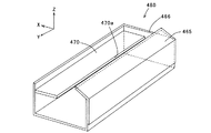
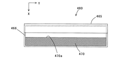
図3はクリーニング装置480を斜め上方から見た外観斜視図、図4はクリーニング装置480の上面図、図5はクリーニング装置480に備えられたトナー堆積部材470の外形図、そして図6はクリーニング装置480の内部寸法図である。尚、図3では、トナーボックス466とトナー堆積部材470の位置関係が見やすいように、トナーボックス466の手前側の側壁は図示していない。
3 is an external perspective view of the
トナー堆積部材470は、図3に示すように長方形の平板状部材であり、図2に示すように、クリーニングブレード465よりも、ベルト移動方向の上流側、且つ鉛直下方に近接配置され、クリーニングブレード465でかき取られた廃トナー472がその上面に溜まるように、トナーボックス466内において棚状に設置されている。トナー堆積部材470は、廃トナー472の影響により固定が外れないように、例えば熱溶着などでトナーボックス466に設置されている。
The
また図6に示すように、クリーニングブレード465とトナー堆積部材470の間には空間Sが形成され、この空間Sはクリーニングブレード465とトナー堆積部材470の相対位置を特定する距離A、Bにより決定される。また、トナー堆積部材470は、その先端部470aが、長手方向においてクリーニングブレード465と平行に配置されている。即ちトナー堆積部材470は、転写ベルト461の幅方向に延在し、且つ転写ベルト461の表面と平行に配置される。尚、距離A、Bについては後述する。
As shown in FIG. 6, a space S is formed between the
以上の構成において、各部の動作について説明する。 The operation of each part in the above configuration will be described.
ドライブローラ462が図1に示す矢印方向に回転することで、転写ベルト461は移動し、各トナー形成部430の感光ドラム431から記録用紙101に画像として転写されなかったトナー471は、図2に示すように、同図矢印方向に移動する転写ベルト461の表面に付着する。図2に示すように、転写ベルト461が移動すると、クリーニングブレード465との接点において転写ベルト461の表面に付着するトナー471が掻き落とされて清掃され、そのトナー471は廃トナー472としてトナーボックス466内へ収納される。
As the
ここで、仮にトナー堆積部材470が備えられていない場合を想定し、そのときの動作について説明する。
Here, assuming that the
転写部460(図1)では、転写ベルト461上に付着するトナー471が微量である場合、クリーニングブレード465に充分なトナー471が供給されないため、転写ベルト461が移動駆動されてクリーニングブレード465と摺動が進むに連れて、クリーニングブレード465の表面に予め潤滑剤として塗布してあるトナーが減少し、転写ベルト461とクリーニングブレード465との摩擦が次第に増大する。この摩擦の増大により、クリーニングブレード465の先端部でめくれが発生する。例えばA4サイズ横送りの場合、約2000枚の印刷を経過したあたりで、転写ベルト461との摩擦の増大し、クリーニングブレード465の先端部でめくれが発生する。
In the transfer unit 460 (FIG. 1), when the amount of
次に、本実施の形態の転写部460(図1)のようにトナー堆積部材470を備えた場合の動作について説明する。
Next, an operation when the
図2に示すように、クリーニングブレード465によって、転写ベルト461の表面から掻き落とされた廃トナー472の一部は、トナー堆積部材470上に堆積し、やがて転写ベルト461の表面とクリーニングブレード465の先端に届くところまで堆積する。トナー堆積部材470上において所定量以上に堆積しようとする廃トナー472は、空間S(図6)を通って落下してトナーボックス466内に収納される。
As shown in FIG. 2, a part of the
トナー堆積部材470上に堆積した廃トナー472は、転写ベルト461及びクリーニングブレード465に接触して付着し、付着した廃トナー472は、転写ベルト461とクリーニングブレード465との接点での潤滑剤として供給される。
尚、トナー堆積部材470は、後述するように、クリーニングブレード465に予め塗布してある潤滑用のトナーがなくなる前に、堆積する廃トナー472が、転写ベルト461及びクリーニングブレード465に接触して付着し、上記したように転写ベルト461とクリーニングブレード465との接点での潤滑剤として供給されるように、クリーニングブレード465との空間Sが調整される。
As will be described later, the
以上のように、本実施の形態のクリーニング装置480では、トナー堆積部材470に堆積する廃トナー472を、転写ベルト461とクリーニングブレード465との接点に潤滑剤として供給するように動作する。これにより、転写ベルト461とクリーニングブレード465との間の摩擦増加を軽減し、クリーニングブレード465の先端でのめくれ発生を防止する。
As described above, the
クリーニングブレード465とトナー堆積部材470の間に形成する空間Sについて、図6を参照しながら更に説明する。
The space S formed between the
空間Sが狭くなると、転写ベルト461の表面から掻き落とされた廃トナー472の、トナー堆積部材470上に堆積する割合が増加し、空間Sが広くなると、転写ベルト461の表面から掻き落とされた廃トナー472の、トナー堆積部材470上に堆積する割合が減少する。従って、空間Sが狭くなると、トナー堆積部材470に堆積した廃トナー472(図2)の、転写ベルト461とクリーニングブレード465への接触圧力が高くなり過ぎ、転写ベルト461の表面に付着するトナー471(図2)をクリーニングブレード465が十分に清掃できず、トナー471のすり抜けが発生する。また、逆に空間Sが広くなると、廃トナー472をクリーニングブレード465と転写ベルト461の接点に充分に供給できないため、クリーニングブレード465の先端にめくれが発生する。また、トナー堆積部材470上にトナーが溜まり始めてからクリーニングブレード465と転写ベルト461との接点に堆積した廃トナー472(図2)が届くまでの時間も空間Sにより決定される。
When the space S narrows, the ratio of the
空間Sは、トナー堆積部材470とクリーニングブレード465における相対位置を決める距離A,Bによって決まる。尚、距離Aは、トナー堆積部材470から転写ベルト461の表面までの距離であり、距離Bは、転写ベルト搬送方向におけるトナー堆積部材470の先端部470aと、クリーニングブレード465と転写ベルト461の接点までの距離である。
The space S is determined by distances A and B that determine the relative positions of the
また、組立て時に予めクリーニングブレード465に塗布した潤滑剤としてのトナーは、例えばA4サイズの用紙を横送りで印刷するような場合は、印刷枚数で2000枚ほどでなくなるため、それより短い時間で、トナー堆積部材470に堆積した廃トナーが、クリーニングブレード465と転写ベルト461との接点に届くように距離A,Bを設定する必要がある。
In addition, the toner as a lubricant applied to the
ここで、距離A,Bと、クリーニングブレード465に対するトナー供給性及びクリーニングブレード465による転写ベルト461のクリーニング性能の関係を調べた実験について説明する。
Here, an experiment in which the relationship between the distances A and B, the toner supply performance to the
クリーニングブレード465を厚み2mmのウレタンゴムで構成し、トナー堆積部材470を剛体として成形した装置において、下記の条件の下に距離A,Bを種々に設定して印刷実験を行った。
実験条件は以下の通りである。
・印刷用紙 A4横
・印刷枚数 2000枚
・印刷パターン 罫線のパターン(低デューティ)
・環境温度及び湿度 28℃、80%
In an apparatus in which the
The experimental conditions are as follows.
-Printing paper A4 landscape-Number of printed sheets 2000-Print pattern Ruled line pattern (low duty)
・ Ambient temperature and humidity 28 ℃, 80%
この実験結果による、クリーニングブレード465に対するトナー供給性、及びクリーニングブレード465による転写ベルト461のクリーニング性能の評価を表1に示す。
同表中の各確認項目の○、×の評価基準は以下の通りである。
・トナー供給が○とは、
2000枚印刷後、トナー堆積部材470上の廃トナーが図2に示すようにクリーニングブレード465端に達している場合に相当する。
・トナー供給が×とは、
2000枚印刷後、トナー堆積部材470上の廃トナーがクリーニングブレード465端に達していない状態に相当する。
・クリーニング○とは、印刷した記録用紙の裏面に汚れが発生していない場合に相当する。(クリーニング不良が発生すると、転写ベルト461の表面に付着したトナーが掻き取れないため、記録用紙裏面に汚れが発生する。)
・クリーニング×とは、印刷した記録用紙の裏面に汚れが発生した場合に相当する。
Table 1 shows the evaluation of the toner supply performance to the
The evaluation criteria for ○ and × for each confirmation item in the table are as follows.
・ Toner supply is ○
This corresponds to the case where the waste toner on the
・ Toner supply is x
This corresponds to a state in which the waste toner on the
-Cleaning ○ corresponds to the case where there is no stain on the back side of the printed recording paper. (If a cleaning failure occurs, the toner adhering to the surface of the
“Cleaning x” corresponds to a case where the back side of the printed recording paper is stained.

この実験結果より、トナー堆積部材470とクリーニングブレード465のとの位置関係、つまり距離A、Bは、下記の条件を満たす範囲のとき、廃トナーを効果的にクリーニングブレード465と転写ベルト461の接点に供給する事ができると判断できる。
2.0mm<B<3.0mm且つ3.0mm<A<8.0mm
又は、0.0mm<B<1.0mm且つ5.0mm<A<9.0mm
又は、B=0.0mm且つ A=10.0mm
From this experimental result, when the positional relationship between the
2.0 mm <B <3.0 mm and 3.0 mm <A <8.0 mm
Or 0.0 mm <B <1.0 mm and 5.0 mm <A <9.0 mm
Or B = 0.0mm and A = 10.0mm
以上のように、本実施の形態の画像形成装置によれば、トナー堆積部材470をクリーニングブレード465から所定の距離を保って配置することにより、トナー堆積部材470に廃トナー472を堆積し、転写ベルト461とクリーニングブレード465との接点に潤滑剤としての廃トナー472を適量供給して転写ベルト461とクリーニングブレード465の摩擦増加を抑制することができる。これにより、クリーニングブレード465の先端めくれを防止し、転写ベルト461の表面に付着したトナー471(図2)のクリーニング不良を防止することができる。
As described above, according to the image forming apparatus of the present embodiment, by disposing the
実施の形態2.
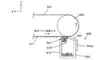
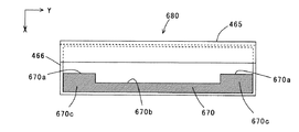
図7は、本発明に基づく実施の形態2の画像形成装置に採用されるクリーニングブレード465、トナーボックス466を備えたクリーニング装置680の周辺を部分的に拡大した部分拡大図、図8はこのクリーニング装置680を斜め上方から見た外観斜視図、図9はクリーニング装置680の上面図、そして図10はクリーニング装置680に備えられたトナー堆積部材670の外形図である。尚、図8において、トナーボックス466とトナー堆積部材670の位置関係が見やすいように、トナーボックス466の手前側の側壁は図示していない。
Embodiment 2. FIG.
FIG. 7 is a partially enlarged view in which the periphery of the
このクリーニング装置680を採用する画像形成装置が、前記した図2に示す実施の形態1のクリーニング装置480と主に異なる点は、トナー堆積部材670の形状である。従って、このクリーニング装置680を採用する画像形成装置が、前記した実施の形態1の画像形成装置1000(図1)と共通する部分には同符号を付して、或いは図面を省いて説明を省略し、異なる点を重点的に説明する。尚、本実施の形態の画像形成装置の要部構成は、トナー堆積部材670以外において図1に示す実施の形態1の画像形成装置1000の要部構成と共通するため、必要に応じて図1を参照する。
The main difference between the image forming apparatus employing the
図7から図10に示すように、本実施の形態におけるトナー堆積部材670は、前記した実施の形態1で説明したトナー堆積部材470(図5参照)と同様の平板状部材であるが、クリーニングブレード465に対向する側において、所定部を中心振分けに切り欠いた切り欠き凹部670bが形成され、よってその両側には、先端部670aを有する凸部670cが形成されている。
As shown in FIGS. 7 to 10, the
図11はクリーニング装置680の内部寸法図である。同図に示すように、クリーニングブレード465とトナー堆積部材670の凸部670cの先端部670a間には空間Sが形成され、この空間Sはクリーニングブレード465とトナー堆積部材670の相対位置を特定する距離A,Bにより決定される。このように、トナー堆積部材670は、その凸部670cの先端部670aが、長手方向においてクリーニングブレード465と平行に配置されている。即ちトナー堆積部材670は、転写ベルト461の幅方向に延在し、且つ転写ベルト461の表面と平行に配置される。
FIG. 11 is an internal dimension diagram of the
尚、距離Aは、トナー堆積部材670から転写ベルト461の表面までの距離であり、距離Bは、転写ベルト搬送方向におけるトナー堆積部材670の凸部670cの先端部670aと、クリーニングブレード465と転写ベルト461の接点までの距離であり、これらの最適条件は、前記した実施の形態1での説明に準じるため、ここでの説明は省略する。
The distance A is the distance from the
ここで、本実施の形態のように、トナー堆積部材670において、上記切り欠き凹部670bを設けた理由について説明する。
Here, the reason why the
例えば図7に示すようなクリーニング装置680において、本実施の形態のようにトナー堆積部材670を備えない場合、前記したようにクリーニングブレード465の転写ベルト461との当接部においてめくれが発生し、特にその長手方向の両端部においてのめくれがより発生しやすいことが知られている。
For example, in the
これは、記録用紙101に印刷する際、印刷可能範囲外に位置するクリーニングブレード465の両端部には、感光ドラム431(図1)から転写ベルト461を介して供給される潤滑剤としてのトナー471が不足するためである。また、クリーニングブレード465自体の先端部構成においても、両側に部材が続くその中央部に比べ、端部側が支持されずに開放状態となっている両端部の強度が低く、このために両端部でめくれがより発生しやすくなっている。一方、印刷範囲内に位置する部分では、転写ベルト461の表面に付着するトナー471が、潤滑剤として、クリーニングブレード465の転写ベルト461との当接部に供給されるため、不足状態となる可能性は低い。
This is because
以上の理由から、本実施の形態のクリーニング装置680では、少なくもクリーニングブレード465の両端部で、トナー堆積部材670に堆積する廃トナー472を潤滑剤として適量供給し、印刷範囲内に位置する部分ではその供給量が制限されるように、所定部を中心振分けに切り欠いた深さdの切り欠き凹部670bを設けている。
For the reasons described above, in the
以上の構成において、各部の動作について更に説明する。 In the above configuration, the operation of each unit will be further described.
ドライブローラ462が図1に示す矢印方向に回転することにより転写ベルト461は移動し、各トナー形成部430の感光ドラム431から記録用紙101に画像として転写されなかったトナー471は、図7に示すように、同図矢印方向に移動する転写ベルト461の表面に付着する。図7に示すように、転写ベルト461が移動すると、クリーニングブレード465との接点において転写ベルト461の表面に付着するトナー471が掻き落とされて清掃され、そのトナー471は廃トナー472としてトナーボックス466内へ収納される。
As the
クリーニングブレード465によって、転写ベルト461の表面から掻き落とされた廃トナー472の一部は、トナー堆積部材670上に堆積し、やがて転写ベルト461の表面とクリーニングブレード465の先端に届くところまで堆積する。トナー堆積部材670上において所定量以上に堆積しようとする廃トナー472は、切り欠き部670bを含む空間を通って落下してトナーボックス466内に収納され、更に一部はトナー堆積部材670の長手方向、例えば中央部から両端部側へも移動する。
A part of the
トナー堆積部材670には、クリーニングブレード465に対向する側において、前記した切り欠き凹部670bが形成されているため、特にその両側の凸部670cにおいて、堆積した廃トナー472が、転写ベルト461及びクリーニングブレード465に接触して付着し、付着した廃トナー472が、転写ベルト461とクリーニングブレード465との接点での潤滑剤として供給される。一方、切り欠き凹部670bが形成された中央部では、堆積量も少なく、クリーニングブレード465からの距離も大きいため、クリーニングブレード465の対向する箇所に供給する廃トナーの量が抑制される。
The
尚、トナー堆積部材670の両端部に位置する凸部670cには、前記したように、端部近傍の転写ベルト461にトナー471が付着し難いことから、中央部に比べ廃トナー472は堆積し難いが、トナー堆積部材670の中央側に堆積した廃トナー472が移動してくることにより堆積を補助する。
As described above, the
クリーニングブレード465と転写ベルト461との当接部に、潤滑剤として供給する廃トナー472の量が多過ぎると、クリーニングブレード465に過剰の負荷がかかって廃トナー472のすり抜けが発生する。そのためトナー堆積部材670において、トナー471の供給量が比較的多く、クリーニングブレード465のめくれが発生しにくい中央部に対応する箇所には切り欠き凹部670bを設け、クリーニングブレード465との距離を広く取って廃トナー472の供給量を減らしている。
If the amount of
図12は、本実施の形態におけるトナー堆積部材の変形例を示す上面図である。 FIG. 12 is a top view showing a modified example of the toner accumulation member in the present embodiment.
前記したように、クリーニングブレード465の両端部は強度が弱いため、図8に示すトナー堆積部材670の両端部に位置する凸部670cにおける廃トナー472の過剰の堆積は、すり抜けを発生させてしまう原因となる。また、トナー堆積部材670の凸部670cに堆積した廃トナー472は、更にその外側に向う長手方向への移動がトナーボックス466により規制されている。このため、切り欠き部670bを含む空間S側にしか移動できないため、廃トナー472が両端部で次々堆積し、その結果、すり抜けを発生させてしまう可能性がある。
As described above, since both ends of the
この問題を解消するため、図12に示す変形例のトナー堆積部材670´では、その両側において、トナーボックス466との間に空間Sbを設けるようにそのサイズを設定し、この空間Sb部分から廃トナーが落下できるようにして、トナー堆積部材670´の両端部での過剰な堆積を防ぐ形状としている。
In order to solve this problem, in the
以上のように、本実施の形態の画像形成装置によれば、印刷可能範囲外に位置して、転写ベルトの表面に付着するトナーの供給が不足するクリーニングブレードの両端部に適量の廃トナーを潤滑剤として供給し、且つ付着トナーが十分供給され、めくれが発生しにくい状態のクリーニングブレードの中央部においては、廃トナーの供給が過剰にならないように設定し、バランスよく廃トナーを供給できるため、中央部におけるすり抜けによるクリーニング効果の低下と、両端部におけるクリーニングブレードのめくれの発生とを共に抑制することができる。 As described above, according to the image forming apparatus of the present embodiment, an appropriate amount of waste toner is placed on both ends of the cleaning blade that is located outside the printable range and is insufficiently supplied with toner adhering to the surface of the transfer belt. In the central part of the cleaning blade, which is supplied as a lubricant and is sufficiently supplied with adhering toner and is not likely to be turned over, the waste toner can be supplied in a well-balanced manner so as not to supply excessive waste toner. Thus, it is possible to suppress both the deterioration of the cleaning effect due to slipping through the central portion and the occurrence of turning up of the cleaning blade at both end portions.
実施の形態3.
図13は、本発明に基づく実施の形態3の画像形成装置に採用されるクリーニングブレード465、トナーボックス466を備えたクリーニング装置780の周辺を部分的に拡大した部分拡大図、図14はこのクリーニング装置780を斜め上方から見た外観斜視図、図15はクリーニング装置780の上面図、そして図16はクリーニング装置780に備えられたトナー堆積部材770の外形図である。尚、図14において、トナーボックス466とトナー堆積部材770の位置関係が見やすいように、トナーボックス466の手前側の側壁は図示していない。
Embodiment 3 FIG.
13 is a partially enlarged view in which the periphery of the
このクリーニング装置780を採用する画像形成装置が、前記した図2に示す実施の形態1のクリーニング装置480と主に異なる点は、トナー堆積部材770の形状である。従って、このクリーニング装置780を採用する画像形成装置が、前記した実施の形態1の画像形成装置1000(図1)と共通する部分には同符号を付して、或いは図面を省いて説明を省略し、異なる点を重点的に説明する。尚、本実施の形態の画像形成装置の要部構成は、トナー堆積部材770以外において図1に示す実施の形態1の画像形成装置1000の要部構成と共通するため、必要に応じて図1を参照する。
The main difference between the image forming apparatus employing the
図13から図16に示すように、本実施の形態におけるトナー堆積部材770は、前記した実施の形態1で説明したトナー堆積部材470(図5参照)と同様の平板状部材であるが、クリーニングブレード465に対向する側において、所定部を中心振分けに切り欠いた切り欠き凹部770bと、両端部を切り欠いた端部切り欠き部770d,770dが形成され、よってその切り欠き部以外には、先端部770aを有する凸部770cが形成されている。
As shown in FIGS. 13 to 16, the
図17はクリーニング装置780の内部寸法図である。同図に示すように、クリーニングブレード465とトナー堆積部材770の凸部770cの先端部670a間には空間Sが形成され、この空間Sはクリーニングブレード465とトナー堆積部材770の相対位置を特定する距離A,Bにより決定される。このように、トナー堆積部材770は、その凸部770cの先端部770aが、長手方向においてクリーニングブレード465と平行に配置されている。即ちトナー堆積部材770は、転写ベルト461の幅方向に延在し、且つ転写ベルト461の表面と平行に配置される。
FIG. 17 is an internal dimension diagram of the
尚、距離Aは、トナー堆積部材770から転写ベルト461の表面までの距離であり、距離Bは、転写ベルト搬送方向におけるトナー堆積部材770の凸部770cの先端部770aと、クリーニングブレード465と転写ベルト461の接点までの距離であり、これらの最適条件は、前記した実施の形態1での説明に準じるため、ここでの説明は省略する。
The distance A is the distance from the
ここで、本実施の形態のように、トナー堆積部材770において、上記切り欠き凹部770b及び端部切り欠き部770dを設けた理由について説明する。
Here, the reason why the
例えば図13に示すようなクリーニング装置780において、本実施の形態のようにトナー堆積部材770を備えない場合、前記したようにクリーニングブレード465の転写ベルト461との当接部においてめくれが発生し、特に特定のサイズの記録用紙101を続けて印刷する場合においては、その記録用紙101の幅方向の端部に対応する部分にめくれが発生しやすいことが知られている。
For example, in the
このめくれの発生は、次の理由による。即ち、決まった大きさの記録用紙101を大量に印刷するような場合、記録用紙101の幅方向の端部は印刷範囲外であり、また、感光ドラム431と転写ベルト461が記録用紙101の厚みによって感光ドラム431と転写ベルト461の非接触部分が発生し、その部分にはトナーや紙粉などが付着し難いと考えられる。それにより記録用紙101の幅方向の端部では、転写ベルト461上にトナー471が付着しないため、転写ベルト461が移動してクリーニングブレード465と摺動する際に、クリーニングブレード465にトナー471が供給されず、クリーニングブレード465の表面に予め塗布してあるトナーが減少し、転写ベルト461とクリーニングブレード465との摩擦が増大するため、記録用紙101の幅方向の端部においてめくれが発生しやすくなる。
This turn-up occurs for the following reason. That is, when a large amount of
一方、用紙101の幅方向の端部以外の領域では、転写ベルト461の表面に付着するトナー471が、潤滑剤として、クリーニングブレード465の転写ベルト461との当接部に供給されるため、不足状態となる可能性は低い。
On the other hand, the
以上の理由から、本実施の形態のクリーニング装置780では、少なくともクリーニングブレード465の、記録用紙101の幅方向の端部に対応する部分で、トナー堆積部材770に堆積する廃トナー472を潤滑剤として適量供給し、それ以外の部分ではその供給量が制限される構成としている。このため、図15に示すように、トナー堆積部材770の各凸部770cの幅方向中心が、記録用紙101の搬送幅の幅端部位置と略一致するように、深さdの切り欠き凹部770b及び端部切り欠き部770dを設け、且つ配置している。
For the above reasons, in the
以上の構成において、各部の動作について更に説明する。 In the above configuration, the operation of each unit will be further described.
ドライブローラ462が図1に示す矢印方向に回転することにより転写ベルト461は移動し、各トナー形成部430の感光ドラム431から記録用紙101に画像として転写されなかったトナー471は、図13に示すように、同図矢印方向に移動する転写ベルト461の表面に付着する。図13に示すように、転写ベルト461が移動すると、クリーニングブレード465との接点において転写ベルト461の表面に付着するトナー471が掻き落とされて清掃され、そのトナー471は廃トナー472としてトナーボックス466内へ収納される。
As the
クリーニングブレード465によって、転写ベルト461の表面から掻き落とされた廃トナー472の一部は、トナー堆積部材770上に堆積し、やがて転写ベルト461の表面とクリーニングブレード465の先端に届くところまで堆積する。トナー堆積部材770上において所定量以上に堆積しようとする廃トナー472は、切り欠き凹部770b及び端部切り欠き部770dを含む空間を通って落下してトナーボックス466内に収納され、更に一部はトナー堆積部材770の長手方向、例えば中央部から両端部側へも移動する。
Part of the
トナー堆積部材770には、クリーニングブレード465に対向する側において、前記した切り欠き凹部770b及び端部切り欠き部770dが形成されているため、特にその両側の凸部770cにおいて、堆積した廃トナー472が、転写ベルト461及びクリーニングブレード465に接触して付着し、付着した廃トナー472が、転写ベルト461とクリーニングブレード465との接点での潤滑剤として供給される。一方、切り欠き凹部770bが形成された中央部では、堆積量も少なく、クリーニングブレード465からの距離も大きいため、クリーニングブレード465の対向する箇所に供給する廃トナーの量が抑制される。
The
尚、トナー堆積部材770の凸部770cには、前記したように、記録用紙101の幅方向の端部では転写ベルト461上にトナー471が付着しないため廃トナー472は堆積し難いが、トナー堆積部材770の中央側に堆積した廃トナー472が移動してくることにより堆積を補助する。
As described above, the
クリーニングブレード465と転写ベルト461との当接部に、潤滑剤として供給する廃トナー472の量が多過ぎると、クリーニングブレード465に過剰の負荷がかかって廃トナー472のすり抜けが発生する。そのためトナー堆積部材770において、トナー471の供給量が比較的多く、クリーニングブレード465のめくれが発生しにくい中央部に対応する箇所には切り欠き凹部770bを設け、クリーニングブレード465との距離を広く取って廃トナー472の供給量を減らしている。
If the amount of
図18は、本実施の形態におけるトナー堆積部材の変形例を示す外形図である。 FIG. 18 is an outline view showing a modified example of the toner accumulation member in the present embodiment.
多種類のサイズの記録用紙が使用される場合には、同図に示すトナー堆積部材770´のように、多種類の記録用紙の幅端部位置(例えばaa,bb)に対応する位置に、中心振り分けされた凸部770cを形成し、前記したように各記録用紙の幅端部位置に対応するクリーニングブレード465と転写ベルト461との接点に適量の廃トナー472を供給する形状とすることができる。図18には、2種類の記録用紙101a,101bの幅端部位置aa,bbに対応して凸部770cを形成した例を示している。
When recording papers of various types are used, like the toner accumulation member 770 'shown in the figure, at positions corresponding to the width end positions (for example, aa, bb) of the various types of recording papers, A center-distributed
尚、本実施の形態におけるトナー堆積部材465は、前記した実施の形態2で説明した、クリーニングブレード465の、その長手方向の両端部に廃トナーを供給する形状と組み合わせることで、記録用紙101の幅方向の端部に対応する部分でのクリーニングブレード465のめくれに加え、両端部におけるクリーニングブレードのめくれの発生を抑制することができる。
The
以上のように、本実施の形態の画像形成装置によれば、記録用紙の幅端部に位置して、転写ベルトの表面に付着するトナーの供給がみこめないクリーニングブレードの対応部分に適量の廃トナーを潤滑剤として供給し、且つ付着トナーが十分供給され、めくれが発生しにくい状態のクリーニングブレードの中央部においては、廃トナーの供給が過剰にならないように設定し、バランスよく廃トナーを供給できるため、中央部におけるすり抜けによるクリーニング効果の低下と、記録用紙の幅端部に対応する位置におけるクリーニングブレードのめくれの発生とを、共に抑制することができる。 As described above, according to the image forming apparatus of the present embodiment, an appropriate amount is applied to the corresponding portion of the cleaning blade that is positioned at the width end portion of the recording paper and does not receive the supply of toner attached to the surface of the transfer belt. In the central part of the cleaning blade where waste toner is supplied as a lubricant and adhering toner is sufficiently supplied and is not likely to be turned over, the waste toner is set so as not to be excessively supplied. Since it can be supplied, it is possible to suppress both the deterioration of the cleaning effect due to slipping through the central portion and the occurrence of turning of the cleaning blade at the position corresponding to the width end portion of the recording paper.
実施の形態4.
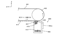
図19は、本発明に基づく実施の形態4の画像形成装置に採用されるクリーニングブレード465、トナーボックス466を備えたクリーニング装置880の周辺を部分的に拡大した部分拡大図である。
Embodiment 4 FIG.
FIG. 19 is a partially enlarged view in which the periphery of the
このクリーニング装置880を採用する画像形成装置が、前記した図2に示す実施の形態1のクリーニング装置480と主に異なる点は、トナー堆積部材870の構成である。従って、このクリーニング装置880を採用する画像形成装置が、前記した実施の形態1の画像形成装置1000(図2)と共通する部分には同符号を付して、或いは図面を省いて説明を省略し、異なる点を重点的に説明する。尚、本実施の形態の画像形成装置の要部構成は、トナー堆積部材870以外において図1に示す実施の形態1の画像形成装置1の要部構成と共通するため、必要に応じて図1を参照する。
The image forming apparatus employing the
本実施の形態におけるトナー堆積部材870は、弾性体である例えばPET(Polyethylene terephthalate)を材料としたマイラフィルムによって形成されている。トナー堆積部材870は、一端がトナーボックス466の内側の所定位置に例えば両面テープなどにより設置される。このトナー堆積部材870の取り付け位置及び形状は、例えば、前記した実施の形態3における図17において説明した、トナー堆積部材770の取り付け位置及び形状を特定する空間S、距離A、Bに準じて設定されるものとする。
The
このトナー堆積部材870は、廃トナー472の堆積量に応じて撓みが増し、空間Sが拡大するように設けられている。以上の構成において、各部の動作について更に説明する。
The
ドライブローラ462が図1に示す矢印方向に回転することにより転写ベルト461は移動し、各トナー形成部430の感光ドラム431から記録用紙101に画像として転写されなかったトナー471は、図19に示すように、同図矢印方向に移動する転写ベルト461の表面に付着する。図19に示すように、転写ベルト461が移動すると、クリーニングブレード465との接点において転写ベルト461の表面に付着するトナー471が掻き落とされて清掃され、そのトナー471は廃トナー472としてトナーボックス466内へ収納される。
As the
クリーニングブレード465によって、転写ベルト461の表面から掻き落とされた廃トナー472の一部は、トナー堆積部材870上に堆積し、やがて転写ベルト461の表面とクリーニングブレード465の先端に届くところまで堆積する。トナー堆積部材870上において所定量以上に堆積しようとする廃トナー472は、空間Sを通って落下してトナーボックス466内に収納される。
A part of the
トナー堆積部材870上に堆積した廃トナー472は、転写ベルト461、及びクリーニングブレード465に接触して付着し、付着した廃トナー472が、転写ベルト461とクリーニングブレード465との接点での潤滑剤として供給される。
The
ここで、環境変化などにより廃トナー472の流動性が低くなった場合について考えてみる。このとき、トナー堆積部材870上に堆積した廃トナー472は、空間Sからトナーボックス466に移動し難くなり、過剰に増加してトナー堆積部材870上にあふれる状態となる。仮にトナー堆積部材870が弾性を有さない場合、やがて、あふれた廃トナー472によってクリーニングブレード465に過剰な圧力が加わるようになり、廃トナー472のすり抜けが発生するようになる。
Here, a case where the fluidity of the
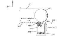
一方、本実施の形態のトナー堆積部材870は、上記したように、所定の弾性を有するマイラフィルムで成形されているため、トナー堆積部材870上に多量の廃トナー472が堆積してクリーニングブレード465に圧力が加わるようになると、その反作用による力と廃トナー472の重量によって、図20に示すようにトナー堆積部材870が撓み、クリーニングブレード465に加わる圧力が軽減される。これにより、廃トナー472の過剰供給によるすり抜けの発生を防止する。
On the other hand, the
また、このときのトナー堆積部材870の撓みにより空間Sが拡大されるため、廃トナー472がトナーボックス466に落下しやすくなり、トナー堆積部材870上に過剰に堆積した廃トナー472がトナーボックス466に落下して収納される。これにより、トナー堆積部材870上の廃トナーの量が適量に抑えられ、適した量の廃トナー472がクリ一二ングブレード465と転写ベルト461との接点に供給されるように作用する。
In addition, since the space S is expanded due to the deflection of the
以上のように、本実施の形態の画像形成装置によれば、トナー堆積部材870を弾性体であるマイラフィルムで成形したことで、トナー堆積部材870上に堆積した廃トナー472が増加した場合に、クリーニングブレード465への圧力が軽減されるため、廃トナー472の過剰供給によるすり抜けの発生を抑えることができる。同時に、適量の廃トナー472をクリ一二ングブレード465と転写ベルト461との接点に供給するため、クリーニングブレード465のめくれの発生を抑えることができる。
As described above, according to the image forming apparatus of the present embodiment, when the
実施の形態5.
図21は、本発明に基づく実施の形態5の画像形成装置に採用されるクリーニングブレード465、トナーボックス466を備えたクリーニング装置980の周辺を部分的に拡大した部分拡大図である。
Embodiment 5 FIG.
FIG. 21 is a partially enlarged view in which the periphery of the
このクリーニング装置980を採用する画像形成装置が、前記した図2に示す実施の形態1のクリーニング装置480と主に異なる点は、トナー堆積部材470に代えて、潤滑剤供給部としての攪拌装置990を備えた点である。従って、このクリーニング装置980を採用する画像形成装置が、前記した実施の形態1の画像形成装置1000(図2)と共通する部分には同符号を付して、或いは図面を省いて説明を省略し、異なる点を重点的に説明する。尚、本実施の形態の画像形成装置の要部構成は、攪拌装置990以外において図1に示す実施の形態1の画像形成装置1の要部構成と共通するため、必要に応じて図1を参照する。
The image forming apparatus employing the
本実施の形態におけるクリーニング装置980は、図21に示すように、トナーボックス466内に攪拌装置990を備えた構成となっている。攪拌装置990はトナーボックス466の長手方向(Y軸方向)に延在し、図示しない駆動手段によって回転駆動されるシャフト990aと、同じく長手方向に延在して一端側がシャフト990aに取付けられた複数の攪拌フィルム990bとからなり、シャフト990aが同図矢印方向に回転することによって、各攪拌フィルム990bがトナーボックス466内に収納された廃トナー472を攪拌し、更には巻き上げるように作用する。
As shown in FIG. 21, the
尚、図21に示した例では、大きなトナーボックス466に対応して、供給する廃トナーを効率よく攪拌するため、シャフト990aに複数枚の攪拌フィルム990bを取付けた例を示したが、トナーボックス466が小さい場合には、シャフト990aに取り付ける攪拌フィルム990bを1枚にしても、十分に効果が得られる。
In the example shown in FIG. 21, in order to efficiently stir the supplied waste toner corresponding to the
以上のように、本実施の形態の画像形成装置によれば、攪拌装置990によって巻き上げられた廃トナー472の一部が、クリ一二ングブレード465と転写ベルト461との接点に潤滑剤として供給されるため、転写ベルト461とクリーニングブレード465の摩擦増加を抑制し、クリーニングブレード465の先端めくれを防止することが出来る。これにより、転写ベルト461上のトナー471(図2)のクリーニング不良を防止することができる。
As described above, according to the image forming apparatus of the present embodiment, a part of the
図22は、本実施の形態の変形例を示すクリーニング装置1010の周辺を部分的に拡大した部分拡大図であり、図23は、このクリーニング装置1010の内部構成を示す部分斜視図である。尚、図23において、クリーニングブレードは、簡単のためその外形のみを点線で示している。
FIG. 22 is a partially enlarged view in which the periphery of the
前記した図21に示す本実施の形態のクリーニング装置980では、攪拌フィルム990bが設けられた攪拌シャフト990aを回転させることで、トナーボックス466内の廃トナー472を転写ベルト461とクリーニングブレード465に供給する構成とした。しかし、図22及び図23に示すクリーニング装置1010のように、廃トナー472を搬送するスパイラル(スプリング)1011に攪拌フィルム1012を装着することによっても、同様の効果を得ることができる。
In the
この場合、トナーボックス466の外部の図示しない駆動手段により回転されるスパイラル1011によって、トナーボックス466内に堆積した廃トナー472は所定の方向に移動する。それにより、移動してきた廃トナーとその場に堆積していった廃トナーが、スパラル内に設けられた攪拌フィルム1012に接触すると、スパイラル1011に固定されて回転している攪拌フィルム1012は、転写ベルト461とクリーニングブレード465にこれらの廃トナーを供給する。
In this case, the
尚、上述の攪拌フィルム1012は、クリーニングブレード465の所望する箇所へ廃トナーを供給する位置に配置すれば良い。つまり、前記した実施の形態1で説明したように、転写ベルト461のY軸方向全面に廃トナーを供給するように構成しても良いし、前記した実施の形態2〜4で説明したように、転写ベルト461のY軸方向の所定の箇所のみに廃トナーを供給するように構成しても良い。
The stirring
上記した実施の形態では、本発明を、カラー電子写真プリンタの搬送ベルトを掃除する場合を例にして説明したが、像担持体などの残トナーをクリーニングブレードを使用して清掃する装置などにも利用可能である。 In the above-described embodiment, the present invention has been described by taking the case of cleaning the conveyance belt of a color electrophotographic printer as an example. However, the present invention may be applied to an apparatus for cleaning residual toner such as an image carrier using a cleaning blade. Is available.
100 給紙トレイ、 101 記録用紙、 102 用紙載置板、 102a 支持軸、 104 リフトアップレバー、 104a 支持軸、 105 モータ、 106 上昇検知部、 200 用紙繰出し部、 201 ピックアップローラ、 202 フィードローラ、 203 リタードローラ、 204 用紙有無検知部、 205 用紙残量検知部、 300 用紙搬送部、 301 用紙センサ、 302 搬送ローラ対、 303 用紙センサ、 304 搬送ローラ対、 305 書込みセンサ、 400 画像形成部、 430 トナー像形成部、 431 感光ドラム、 432 帯電ローラ、 ヘッド433 LED、 434 現像ローラ、 435 クリーニングブレード、 460 転写部、 461 転写ベルト、 462 ドライブローラ、 463 テンションローラ、 464 転写ローラ、 465 クリーニングブレード、 465a クリーニングブレード取り付け板金、 466 トナーボックス、 467 フィルム、 470 トナー堆積部材、 471 トナー、 472 廃トナー、 480 クリーニング装置、 500 定着ユニット、 501 アッパローラ、 502 ロワローラ、 503 ハロゲンランプ、 504 排出ローラ対、 505 スタッカ部、 670,670´ トナー堆積部材、 670a 先端部、 670b 切り欠き凹部、 670c 凸部、 680 クリーニング装置、 770,770´ トナー堆積部材、 770a 先端部、 770b 切り欠き凹部、 770c 凸部、 770d 端部切り欠き部、 780 クリーニング装置、 870 トナー堆積部材、 880 クリーニング装置、 980 クリーニング装置、 990 攪拌装置、 990a シャフト、 990b 攪拌フィルム、 1000 画像形成装置、 1010 クリーニング装置1010、 1011 スパイラル、 1012 攪拌フィルム。 DESCRIPTION OF SYMBOLS 100 Paper feed tray, 101 Recording paper, 102 Paper mounting plate, 102a Support shaft, 104 Lift up lever, 104a Support shaft, 105 Motor, 106 Lift detection part, 200 Paper feed part, 201 Pickup roller, 202 Feed roller, 203 Retard roller, 204 paper presence / absence detection unit, 205 paper remaining amount detection unit, 300 paper conveyance unit, 301 paper sensor, 302 conveyance roller pair, 303 paper sensor, 304 conveyance roller pair, 305 writing sensor, 400 image forming unit, 430 toner Image forming unit, 431 photosensitive drum, 432 charging roller, head 433 LED, 434 developing roller, 435 cleaning blade, 460 transfer unit, 461 transfer belt, 462 drive roller, 63 Tension roller, 464 Transfer roller, 465 Cleaning blade, 465a Cleaning blade mounting sheet metal, 466 toner box, 467 film, 470 toner accumulation member, 471 toner, 472 waste toner, 480 cleaning device, 500 fixing unit, 501 upper roller, 502 lower roller , 503 Halogen lamp, 504 discharge roller pair, 505 stacker unit, 670, 670 ′ toner accumulation member, 670a tip, 670b notch recess, 670c projection, 680 cleaning device, 770, 770 ′ toner accumulation member, 770a tip , 770b Notched recess, 770c Convex, 770d End notch, 780 Cleaning device, 870 Toner Depositing member, 880 a cleaning device, 980 cleaning device 990 stirrer, 990a shaft, 990b stirred films, 1000 image forming apparatus, 1010 a cleaning apparatus 1010, 1011 spiral, 1012 stirred films.
Claims (15)
前記ベルトの表面に接触して設けられたクリーニング部材と、
前記ベルトと前記クリーニング部材との接触部よりも鉛直下方で水平に配置され、前記ベルトの表面と略平行に、且つ該ベルトの幅方向に延在する棚状部材であって、潤滑剤を堆積し、堆積した前記潤滑剤を前記接触部に供給する潤滑剤堆積部材と、
前記潤滑剤堆積部材よりも鉛直下方に設けられ、前記ベルトに付着し、前記クリーニング部材で掻き落とされた付着物を収納する付着物収納部と
を備え、
前記潤滑剤堆積部材の前記クリーニング部材に最も近い端部が、前記ベルトの前記接触部における移動方向と垂直方向に延在し且つ前記接触部よりも前記移動方向の上流側に位置することを特徴とする画像形成装置。 A belt transport unit including an endless belt movably stretched between at least two support members;
A cleaning member provided in contact with the surface of the belt;
A shelf-like member that is horizontally disposed vertically below the contact portion between the belt and the cleaning member, extends substantially parallel to the surface of the belt, and extends in the width direction of the belt, and deposits lubricant. A lubricant depositing member for supplying the deposited lubricant to the contact portion;
An adhering matter storage unit that is provided vertically below the lubricant depositing member, adheres to the belt, and stores adhering matter scraped off by the cleaning member;
An end portion of the lubricant depositing member that is closest to the cleaning member extends in a direction perpendicular to the moving direction of the belt at the contact portion and is located upstream of the contact portion in the moving direction. An image forming apparatus.
ことを特徴とする請求項1記載の画像形成装置。 The lubricant accumulation member has an end closest to the cleaning member at a position 3.0 mm to 8.0 mm below the contact portion, and 2.0 mm to the upstream side of the belt movement direction from the contact portion. Provided at a position that is 3.0 mm away, or at a position that is 5.0 mm to 9.0 mm below the contact portion, and a position that is 0.0 mm to 1.0 mm away from the contact portion on the upstream side in the belt movement direction The image forming apparatus according to claim 1, wherein the image forming apparatus is provided at a position 10.0 mm below the contact portion and at a position 0.0 mm away from the contact portion on the upstream side in the belt movement direction.
前記ベルトの表面に接触して設けられたクリーニング部材と、
前記ベルトと前記クリーニング部材との接触部よりも鉛直下方に配置され、前記ベルトの表面と略平行に、且つ該ベルトの幅方向に延在する棚状部材であって、潤滑剤を堆積し、堆積した前記潤滑剤を前記接触部に供給する潤滑剤堆積部材と、
前記潤滑剤堆積部材よりも鉛直下方に設けられ、前記ベルトに付着し、前記クリーニング部材で掻き落とされた付着物を収納する付着物収納部と
を備え、
前記潤滑剤堆積部材は、前記ベルト幅方向端部における前記ベルト移動方向の幅が、中央部の幅より広いことを特徴とする画像形成装置。 A belt transport unit including an endless belt movably stretched between at least two support members;
A cleaning member provided in contact with the surface of the belt;
A shelf-like member that is disposed vertically below the contact portion between the belt and the cleaning member, extends substantially parallel to the surface of the belt, and extends in the width direction of the belt, and deposits lubricant. A lubricant depositing member for supplying the deposited lubricant to the contact portion;
An adhering matter storage unit that is provided vertically below the lubricant depositing member, adheres to the belt, and stores adhering matter scraped off by the cleaning member;
In the image forming apparatus, the lubricant accumulation member has a width in the belt moving direction at an end portion in the belt width direction that is wider than a width in a central portion.
ことを特徴とする請求項3記載の画像形成装置。 The lubricant depositing member has an end closest to the cleaning member at a position 3.0 mm to 8.0 mm below the contact portion, and 2.0 mm to 3 mm upstream from the contact portion in the belt moving direction. Provided at a position that is 0.0 mm apart, or at a position that is 5.0 mm to 9.0 mm below the contact portion, and that is 0.0 mm to 1.0 mm away from the contact portion on the upstream side in the moving direction of the belt. 4. The image forming apparatus according to claim 3 , wherein the image forming apparatus is provided at a position 10.0 mm below the contact portion and at a position 0.0 mm away from the contact portion on the upstream side in the moving direction of the belt.
前記トナー付着部材の表面に接触して設けられたクリーニング部材と、
前記トナー付着部材と前記クリーニング部材との接触部よりも鉛直下方で水平に配置され、前記トナー付着部材の表面と略平行に、且つ該トナー付着部材の幅方向に延在する棚状部材であって、潤滑剤を堆積し、堆積した前記潤滑剤を前記接触部に供給する潤滑剤堆積部材と、
前記潤滑剤堆積部材よりも鉛直下方に設けられ、前記トナー付着部材に付着し、前記クリーニング部材で掻き落とされた付着物を収納する付着物収納部と
を備え、
前記潤滑剤堆積部材の前記クリーニング部材に最も近い端部が、前記トナー付着部材の前記接触部における移動方向と垂直方向に延在し且つ前記接触部よりも前記移動方向の上流側に位置することを特徴とする画像形成装置。 A toner adhering member that moves the adhering toner with the toner adhering to the surface;
A cleaning member provided in contact with the surface of the toner adhering member;
A shelf-like member that is horizontally disposed vertically below the contact portion between the toner adhering member and the cleaning member, and extends substantially in parallel with the surface of the toner adhering member and in the width direction of the toner adhering member. A lubricant depositing member for depositing a lubricant and supplying the deposited lubricant to the contact portion;
An adhering matter storage unit provided vertically below the lubricant accumulating member, adhering to the toner adhering member, and containing adhering matter scraped off by the cleaning member;
The end of the lubricant depositing member that is closest to the cleaning member extends in a direction perpendicular to the moving direction of the toner adhering member at the contact portion and is located upstream of the contact portion in the moving direction. An image forming apparatus.
少なくとも2つの支持部材間に移動可能に張設される無端状のベルトを備えたベルト搬送部と、
前記ベルトの表面に接触して設けられたクリーニング部材と、
前記ベルトと前記クリーニング部材との接触部よりも鉛直下方で水平に配置され、前記ベルトの表面と略平行に、且つ該ベルトの幅方向に延在する棚状部材であって、潤滑剤を堆積し、堆積した前記潤滑剤を前記接触部に供給する潤滑剤堆積部材と、
前記潤滑剤堆積部材よりも鉛直下方に設けられ、前記ベルトに付着し、前記クリーニング部材で掻き落とされた付着物を収納する付着物収納部と
を備え、
前記潤滑剤堆積部材の前記クリーニング部材に最も近い端部が、前記ベルトの前記接触部における移動方向と垂直方向に延在し且つ前記接触部よりも前記移動方向の上流側に位置することを特徴とするベルト搬送装置。 In a belt conveyance device for conveying a recording medium,
A belt transport unit including an endless belt movably stretched between at least two support members;
A cleaning member provided in contact with the surface of the belt;
A shelf-like member that is horizontally disposed vertically below the contact portion between the belt and the cleaning member, extends substantially parallel to the surface of the belt, and extends in the width direction of the belt, and deposits lubricant. A lubricant depositing member for supplying the deposited lubricant to the contact portion;
An adhering matter storage unit that is provided vertically below the lubricant depositing member, adheres to the belt, and stores adhering matter scraped off by the cleaning member;
An end portion of the lubricant depositing member that is closest to the cleaning member extends in a direction perpendicular to the moving direction of the belt at the contact portion and is located upstream of the contact portion in the moving direction. Belt conveyor.
Priority Applications (2)
| Application Number | Priority Date | Filing Date | Title |
|---|---|---|---|
| JP2007170451A JP4383468B2 (en) | 2007-06-28 | 2007-06-28 | Belt conveying apparatus and image forming apparatus |
| US12/216,038 US8301070B2 (en) | 2007-06-28 | 2008-06-27 | Belt conveying apparatus and image forming apparatus |
Applications Claiming Priority (1)
| Application Number | Priority Date | Filing Date | Title |
|---|---|---|---|
| JP2007170451A JP4383468B2 (en) | 2007-06-28 | 2007-06-28 | Belt conveying apparatus and image forming apparatus |
Related Child Applications (1)
| Application Number | Title | Priority Date | Filing Date |
|---|---|---|---|
| JP2009188409A Division JP4527185B2 (en) | 2009-08-17 | 2009-08-17 | Image forming apparatus |
Publications (3)
| Publication Number | Publication Date |
|---|---|
| JP2009008904A JP2009008904A (en) | 2009-01-15 |
| JP2009008904A5 JP2009008904A5 (en) | 2009-02-26 |
| JP4383468B2 true JP4383468B2 (en) | 2009-12-16 |
Family
ID=40160681
Family Applications (1)
| Application Number | Title | Priority Date | Filing Date |
|---|---|---|---|
| JP2007170451A Active JP4383468B2 (en) | 2007-06-28 | 2007-06-28 | Belt conveying apparatus and image forming apparatus |
Country Status (2)
| Country | Link |
|---|---|
| US (1) | US8301070B2 (en) |
| JP (1) | JP4383468B2 (en) |
Families Citing this family (15)
| Publication number | Priority date | Publication date | Assignee | Title |
|---|---|---|---|---|
| JP2010262158A (en) | 2009-05-08 | 2010-11-18 | Oki Data Corp | Image forming apparatus |
| JP4759631B2 (en) | 2009-08-05 | 2011-08-31 | シャープ株式会社 | Intermediate transfer member and image forming apparatus |
| JP2011034009A (en) | 2009-08-05 | 2011-02-17 | Sharp Corp | Belt cleaning apparatus and image forming apparatus |
| JP2011043598A (en) * | 2009-08-20 | 2011-03-03 | Konica Minolta Business Technologies Inc | Cleaning apparatus and image forming apparatus |
| JP4781459B2 (en) | 2009-08-28 | 2011-09-28 | シャープ株式会社 | Intermediate transfer member and image forming apparatus |
| JP5538864B2 (en) * | 2009-12-21 | 2014-07-02 | キヤノン株式会社 | Image forming apparatus |
| JP5641793B2 (en) * | 2010-06-25 | 2014-12-17 | キヤノン株式会社 | Toner conveying device or image forming apparatus |
| JP5628766B2 (en) | 2011-08-30 | 2014-11-19 | 株式会社沖データ | Toner adhering unit and image forming apparatus |
| JP5777668B2 (en) * | 2013-08-09 | 2015-09-09 | キヤノン株式会社 | Image heating device |
| JP6111972B2 (en) * | 2013-10-15 | 2017-04-12 | 富士ゼロックス株式会社 | Cleaning device and image forming apparatus |
| JP2015079076A (en) * | 2013-10-16 | 2015-04-23 | 富士ゼロックス株式会社 | Cleaning unit, image holding body unit, and image forming apparatus |
| JP6405264B2 (en) | 2015-02-26 | 2018-10-17 | 株式会社沖データ | Image forming apparatus and image carrier unit |
| JP6602209B2 (en) * | 2016-01-20 | 2019-11-06 | 株式会社沖データ | Image forming apparatus |
| JP6814599B2 (en) | 2016-10-26 | 2021-01-20 | 株式会社沖データ | Developer recovery device, belt unit and image forming device |
| JP2018124537A (en) * | 2017-01-31 | 2018-08-09 | 株式会社沖データ | Belt unit and image forming apparatus |
Family Cites Families (34)
| Publication number | Priority date | Publication date | Assignee | Title |
|---|---|---|---|---|
| US4690544A (en) * | 1985-12-24 | 1987-09-01 | Xerox Corporation | Blade cleaning apparatus for flexible belt |
| US4786937A (en) * | 1987-05-01 | 1988-11-22 | Xerox Corporation | Processing cartridge with one time function sheet |
| JPH01161288A (en) | 1987-12-18 | 1989-06-23 | Canon Inc | Cleaning device for image forming device |
| US5349429A (en) * | 1993-11-09 | 1994-09-20 | Xerox Corporation | Cleaner blade lubricating system |
| JP3234103B2 (en) | 1994-05-19 | 2001-12-04 | 株式会社リコー | Cleaning equipment for electrophotographic equipment |
| US5530537A (en) * | 1994-09-15 | 1996-06-25 | Xerox Corporation | Biased foam roll cleaner |
| US5991568A (en) * | 1998-12-23 | 1999-11-23 | Eastman Kodak Company | Blade cleaning apparatus with associated dust seal and method of cleaning |
| JP2001042726A (en) | 1999-07-30 | 2001-02-16 | Seiko Epson Corp | Image forming device |
| JP3943797B2 (en) | 2000-03-31 | 2007-07-11 | キヤノン株式会社 | Image forming apparatus |
| JP2002323837A (en) | 2001-04-24 | 2002-11-08 | Sharp Corp | Cleaning member, manufacturing method therefor and cleaning device |
| JP3771880B2 (en) | 2002-08-12 | 2006-04-26 | 株式会社沖データ | Toner recovery device |
| JP2004264619A (en) * | 2003-03-03 | 2004-09-24 | Ricoh Co Ltd | Charging roller cleaning mechanism, process cartridge and image forming apparatus |
| KR100518822B1 (en) * | 2003-06-18 | 2005-10-06 | 삼성전자주식회사 | Used toner apparatus for laser printer |
| US7313343B2 (en) * | 2003-08-27 | 2007-12-25 | Seiko Epson Corporation | Image forming apparatus |
| JP2005173305A (en) * | 2003-12-12 | 2005-06-30 | Konica Minolta Business Technologies Inc | Image forming apparatus and method for forming image |
| JP2005173351A (en) * | 2003-12-12 | 2005-06-30 | Samsung Yokohama Research Institute Co Ltd | Cleaning device and image forming system using the same |
| US7302203B2 (en) * | 2004-02-16 | 2007-11-27 | Konica Minolta Business Technologies, Inc. | Image forming apparatus |
| JP2005309404A (en) * | 2004-03-24 | 2005-11-04 | Fuji Xerox Co Ltd | Image forming apparatus and process cartridge |
| US7043188B2 (en) * | 2004-03-30 | 2006-05-09 | Xerox Corporation | Cleaning device for cleaning a moving surface |
| JP2006053213A (en) | 2004-08-10 | 2006-02-23 | Konica Minolta Business Technologies Inc | Image forming apparatus |
| JP2006276158A (en) * | 2005-03-28 | 2006-10-12 | Fuji Xerox Co Ltd | Process cartridge, image forming device, cleaning method, and cleaning apparatus |
| US7720400B2 (en) * | 2005-08-11 | 2010-05-18 | Seiko Epson Corporation | Image forming apparatus with cleaner that removes toner from intermediate transfer medium |
| US7313356B2 (en) * | 2005-10-25 | 2007-12-25 | Oki Data Corporation | Image forming apparatus |
| JP5081641B2 (en) * | 2007-06-15 | 2012-11-28 | 株式会社リコー | Image forming apparatus and process cartridge |
| JP2009139536A (en) * | 2007-12-05 | 2009-06-25 | Konica Minolta Business Technologies Inc | Image forming apparatus |
| JP4665982B2 (en) * | 2008-03-26 | 2011-04-06 | 富士ゼロックス株式会社 | Image forming apparatus |
| JP4462367B2 (en) * | 2008-04-09 | 2010-05-12 | 富士ゼロックス株式会社 | Cleaning device, image forming apparatus using the same, and cleaning tool |
| US8131170B2 (en) * | 2009-06-22 | 2012-03-06 | Xerox Corporation | Method and apparatus for controlling level of marking material in a waste sump |
| JP2011034048A (en) * | 2009-07-09 | 2011-02-17 | Ricoh Co Ltd | Cleaning device, fixing device, and image forming apparatus |
| JP2011043598A (en) * | 2009-08-20 | 2011-03-03 | Konica Minolta Business Technologies Inc | Cleaning apparatus and image forming apparatus |
| JP2011170155A (en) * | 2010-02-19 | 2011-09-01 | Fuji Xerox Co Ltd | Cleaning device, image forming apparatus, and lubricant |
| JP5464487B2 (en) * | 2010-03-18 | 2014-04-09 | 株式会社リコー | Cleaning device and image forming apparatus |
| JP2011248167A (en) * | 2010-05-28 | 2011-12-08 | Konica Minolta Business Technologies Inc | Image forming device |
| JP2012027225A (en) * | 2010-07-23 | 2012-02-09 | Konica Minolta Business Technologies Inc | Cleaning device and image formation apparatus |
-
2007
- 2007-06-28 JP JP2007170451A patent/JP4383468B2/en active Active
-
2008
- 2008-06-27 US US12/216,038 patent/US8301070B2/en active Active
Also Published As
| Publication number | Publication date |
|---|---|
| US8301070B2 (en) | 2012-10-30 |
| JP2009008904A (en) | 2009-01-15 |
| US20090003871A1 (en) | 2009-01-01 |
Similar Documents
| Publication | Publication Date | Title |
|---|---|---|
| JP4383468B2 (en) | Belt conveying apparatus and image forming apparatus | |
| JP4527185B2 (en) | Image forming apparatus | |
| JP4794281B2 (en) | Belt drive device and image forming apparatus having the same | |
| US6035158A (en) | Image forming apparatus and belt unit thereof | |
| US7346295B2 (en) | Belt member and belt device using the same | |
| US8628074B2 (en) | Sheet feeding device and image forming apparatus incorporating same | |
| US7600749B2 (en) | Paper feeding device and image forming apparatus including the same | |
| US20100032891A1 (en) | Sheet feeding device and image forming apparatus | |
| JP4808115B2 (en) | Belt device and image forming apparatus | |
| US8659781B2 (en) | Medium transporting apparatus and image forming apparatus that employs the medium transporting apparatus | |
| JP2008129494A (en) | Belt conveyance device and image forming apparatus | |
| JP6331542B2 (en) | Discharged paper storage device | |
| JP5591572B2 (en) | Medium conveying apparatus and image forming apparatus | |
| US8843051B2 (en) | Medium containing cassette, medium feeding unit, optional medium feeding unit and image forming apparatus | |
| JP5622660B2 (en) | Sheet feeding apparatus and image forming apparatus provided with the same | |
| US20060222427A1 (en) | Paper feeding cassette for preventing double-feed of paper and image forming apparatus with the same | |
| JP2012076880A (en) | Sheet sorting apparatus and image forming apparatus | |
| JP5429634B2 (en) | Sheet conveying apparatus and image forming apparatus | |
| JP2007223783A (en) | Belt conveyance device and image forming device | |
| CN106467247B (en) | Sheet conveying device and image forming apparatus | |
| JP4340524B2 (en) | Image forming apparatus | |
| JP5622661B2 (en) | Sheet feeding apparatus and image forming apparatus provided with the same | |
| JP5958807B2 (en) | Sheet conveying apparatus and image forming apparatus | |
| JP2005193989A (en) | Recording body conveying device and image forming device | |
| JP2006251127A (en) | Image forming apparatus |
Legal Events
| Date | Code | Title | Description |
|---|---|---|---|
| A521 | Request for written amendment filed |
Free format text: JAPANESE INTERMEDIATE CODE: A523 Effective date: 20081120 |
|
| A621 | Written request for application examination |
Free format text: JAPANESE INTERMEDIATE CODE: A621 Effective date: 20081120 |
|
| A977 | Report on retrieval |
Free format text: JAPANESE INTERMEDIATE CODE: A971007 Effective date: 20090408 |
|
| A131 | Notification of reasons for refusal |
Free format text: JAPANESE INTERMEDIATE CODE: A131 Effective date: 20090414 |
|
| A521 | Request for written amendment filed |
Free format text: JAPANESE INTERMEDIATE CODE: A523 Effective date: 20090605 |
|
| A131 | Notification of reasons for refusal |
Free format text: JAPANESE INTERMEDIATE CODE: A131 Effective date: 20090630 |
|
| A521 | Request for written amendment filed |
Free format text: JAPANESE INTERMEDIATE CODE: A523 Effective date: 20090817 |
|
| TRDD | Decision of grant or rejection written | ||
| A01 | Written decision to grant a patent or to grant a registration (utility model) |
Free format text: JAPANESE INTERMEDIATE CODE: A01 Effective date: 20090908 |
|
| A01 | Written decision to grant a patent or to grant a registration (utility model) |
Free format text: JAPANESE INTERMEDIATE CODE: A01 |
|
| A61 | First payment of annual fees (during grant procedure) |
Free format text: JAPANESE INTERMEDIATE CODE: A61 Effective date: 20090918 |
|
| FPAY | Renewal fee payment (event date is renewal date of database) |
Free format text: PAYMENT UNTIL: 20121002 Year of fee payment: 3 |
|
| R150 | Certificate of patent or registration of utility model |
Ref document number: 4383468 Country of ref document: JP Free format text: JAPANESE INTERMEDIATE CODE: R150 Free format text: JAPANESE INTERMEDIATE CODE: R150 |
|
| FPAY | Renewal fee payment (event date is renewal date of database) |
Free format text: PAYMENT UNTIL: 20121002 Year of fee payment: 3 |
|
| FPAY | Renewal fee payment (event date is renewal date of database) |
Free format text: PAYMENT UNTIL: 20131002 Year of fee payment: 4 |
|
| S111 | Request for change of ownership or part of ownership |
Free format text: JAPANESE INTERMEDIATE CODE: R313111 |
|
| R350 | Written notification of registration of transfer |
Free format text: JAPANESE INTERMEDIATE CODE: R350 |