JP4377178B2 - Architectural exterior - Google Patents
Architectural exterior Download PDFInfo
- Publication number
- JP4377178B2 JP4377178B2 JP2003290990A JP2003290990A JP4377178B2 JP 4377178 B2 JP4377178 B2 JP 4377178B2 JP 2003290990 A JP2003290990 A JP 2003290990A JP 2003290990 A JP2003290990 A JP 2003290990A JP 4377178 B2 JP4377178 B2 JP 4377178B2
- Authority
- JP
- Japan
- Prior art keywords
- projecting
- rainwater
- exterior
- accessory
- building exterior
- Prior art date
- Legal status (The legal status is an assumption and is not a legal conclusion. Google has not performed a legal analysis and makes no representation as to the accuracy of the status listed.)
- Expired - Fee Related
Links
Images


Description
本発明は、建物の外装材の上に化粧用の縁材として取り付ける建築用外装役物に関するものである。 The present invention relates to a building exterior accessory to be attached as a decorative rim material on a building exterior material.
近年、建物の外壁には、窯業系外装材を用いて施工されることが多い。
そして、窓等の開口部には化粧や雨仕舞いのために窯業系外装材の上に建築用外装役物が架設して取り付けられる場合がある。
従来の建築用外装役物は断面略矩形状で水平方向に長い長尺物であり、建築用外装役物の施工した状態では建築用外装役物の表面に沿って流れる雨水がそのまま下方に伝い外装材の表面に沿って流れ、建築用外装役物や窯業系外装材の表面に雨水の流れた跡が付き、特にゴミなどと一緒に雨水が流れた時には流れた跡が汚くなり意匠性に問題があると同時に、耐侯性にも問題がある。
In recent years, the exterior walls of buildings are often constructed using ceramic-type exterior materials.
In some cases, an architectural exterior accessory is erected and installed on the ceramics exterior material in the opening of a window or the like for makeup or rain.
Conventional building exterior accessories are long and long in the horizontal direction with a substantially rectangular cross section, and rainwater flowing along the surface of the building exterior accessories is transmitted downward as it is when the exterior exterior building features are installed. It flows along the surface of the exterior material, and traces of rainwater flow are attached to the surface of the exterior exterior building materials and ceramics exterior materials, especially when rainwater flows along with garbage etc. At the same time, there is a problem with weather resistance.
この改善策として、下記の特許文献のように、建築用外装役物の表面に突出部を設け、そこで水を切るようにしたり、さらに突出部の裏に凹部を設けたり、凹部に溝を設けたりして、この水切り機能を向上させている。
しかしながら、大量の雨水が流れた場合には、突出部の裏面を伝って建築用外装役物の下方表面に雨水が伝わる可能性がある。
本発明は、さらに水切り機能を向上させた建築用外装役物を提供するものである。
However, when a large amount of rainwater flows, there is a possibility that the rainwater may be transmitted to the lower surface of the building exterior accessory along the back surface of the protrusion.
The present invention provides a building exterior accessory with a further improved draining function.
上記の課題を解決するために本請求項1に記載の発明は、上端部に傾斜辺とそれに連なる垂直辺とを有し、さらに垂直辺の下端部に垂直辺の表面位置とほぼ同等の位置に頂点を持つ突出片が施されている建築用外装役物である。
上記の構成によれば、雨水を素早く切り、大量の雨水が流れてきても下方への雨水の伝わりをなくすることが出来る。
In order to solve the above problem, the invention according to
According to said structure, rainwater can be cut quickly and even if a large amount of rainwater flows, transmission of rainwater below can be eliminated.
また、本請求項1に記載の発明は、突出片は突出表面斜め辺と突出裏面斜め辺とその両辺に挟まれた突出平坦辺とからなり、前方斜め下に向かって幅が狭くなっており、上記垂直辺と突出表面斜め辺との間には表面側凹部が形成され、突出裏面斜め辺と化粧表面との間には裏面側凹部が形成されている建築用外装役物である。
上記の構成によれば、垂直辺を伝って雨水が下方表面に伝い流れようとするのを、突出片に当たることで雨水を前方斜め下にはじき飛ばすことができるので、大量の雨水が流れてきても、下方への雨水の伝わりをなくすることが出来、雨水の伝いによる汚れも発生しない。
In the invention according to
According to the above configuration, the rainwater tries to flow along the vertical side to the lower surface, but by hitting the protruding piece, the rainwater can be swept forward and obliquely downward, so a large amount of rainwater flows. However, it is possible to eliminate the transmission of rainwater downward, and no contamination is caused by the rainwater transmission.
また、本請求項2に記載の発明は、建築用外装役物の化粧表面は上端部から下端部に向かって階段状に凹み形状になっている建築用外装役物である。
上記の構成によれば、雨水が例え上端部で伝っても、下端部は階段状に凹んでいるので雨水は伝わりにくい。
Further, the invention according to
According to said structure, even if rainwater propagates in an upper end part, since a lower end part is dented in steps, rainwater is hard to be transmitted.
本発明の建築用外装役物は、垂直辺の下端部に垂直辺の表面位置とほぼ同等の位置に頂点を持つ突出片が施されているので、雨水を素早く切り、大量の雨水が流れてきても下方への雨水の伝わりをなくすることが出来る。
また、突出片は突出表面斜め辺と突出裏面斜め辺とその両辺に挟まれた突出平坦辺とからなり、前方斜め下に向かって幅が狭くなっており、上記垂直辺と突出表面斜め辺との間には表面側凹部が形成され、突出裏面斜め辺と化粧表面との間には裏面側凹部が形成されているので、垂直辺を伝って雨水が下方表面に伝い流れようとするのを、突出片に当たることで雨水を前方斜め下にはじき飛ばすことができるので、大量の雨水が流れてきても下方への雨水の伝わりをなくすることが出来、雨水の伝いによる汚れも発生しない。
また、建築用外装役物の化粧表面は上端部から下端部に向かって階段状に凹み形状になっているので、雨水が例え上端部で伝っても、下端部は階段状に凹んでいるので雨水は伝わりにくい。
The building exterior accessory according to the present invention has a protruding piece having a vertex at a position substantially equal to the surface position of the vertical side at the lower end of the vertical side, so that the rainwater is quickly cut and a large amount of rainwater flows. However, the transmission of rainwater downwards can be eliminated.
The projecting piece is composed of a projecting surface oblique side, a projecting back surface oblique side, and a projecting flat side sandwiched between both sides, and has a width narrowing toward the front obliquely lower side. There is a recess on the front side, and a recess on the back side is formed between the projecting back diagonal side and the decorative surface, so rainwater tries to flow along the vertical side to the lower surface. By hitting the projecting piece, rainwater can be blown diagonally forward, so that even if a large amount of rainwater flows, it is possible to eliminate the transmission of rainwater downward, and no contamination is caused by the rainwater transmission.
In addition, the decorative surface of the building exterior accessory has a concave shape in a stepped manner from the upper end to the lower end, so even if rainwater is transmitted through the upper end, the lower end is recessed in a stepped shape. Rainwater is not easily transmitted.
以下図面を用いて、本発明を実施するための最良の形態を説明する。 The best mode for carrying out the present invention will be described below with reference to the drawings.
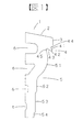
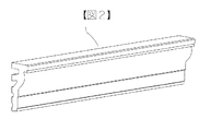
図1は本発明の建築用外装役物の断面図、図2は斜視図である。
本発明の建築用外装役物1は例えば窯業系材料を押出成形して製造される。
建築用外装役物1の上端部には、前方斜め下に傾斜する傾斜辺2、傾斜辺2から下方に垂直に連なる垂直辺3、垂直辺3の下端部に突出片4が施されており、突出片4は突出表面斜め辺41と突出裏面斜め辺43とその両辺に挟まれた突出平坦辺42とからなり、突出表面斜め辺41の垂直辺3の表面位置Rに対する角度αは突出裏面斜め辺43の垂直辺3の表面位置Rに対する角度βよりも鋭角であり、また、前方斜め下に向かって幅が狭くなっている。(図4参照)
そして垂直辺3と突出表面斜め辺41との間には表面側凹部44が、突出裏面斜め辺43と化粧表面5との間には裏面側凹部45が形成されている。
この突出片4の突出表面斜め辺41と突出平坦辺42との頂点部分は垂直辺3の表面位置Rとほぼ同じ位置にある。(図4参照)
突出片4の下方の化粧表面5には、階段状に順次後方へ凹む凹み形状が施されており、51は第1階段状凹部、52は第2階段状凹部、53は第3階段状凹部、54は第4階段状凹部である。
また、建築用外装役物1の裏面側には裏抜き部6が適宜施されている。
ここでいう前方とは建築用外装役物の表面側への方向を、後方とは建築用外装役物の裏面側への方向をいう。
FIG. 1 is a cross-sectional view of a building exterior accessory according to the present invention, and FIG. 2 is a perspective view.
The building
The upper end of the building
A
The apex portions of the projecting surface oblique side 41 and the projecting
The
Further, a back-
Here, the front refers to the direction toward the front side of the architectural exterior accessory, and the rear refers to the direction toward the back side of the architectural exterior accessory.
そして、図3のように開口部まわりに建築用外装役物1を施工する。
101は窯業系外装材、102は縦胴縁、103は横胴縁、104はサッシ、105はバックアップ材、106はシ−リング材、107は釘である。
Then, as shown in FIG. 3, the building
101 is a ceramic exterior material, 102 is a vertical trunk edge, 103 is a horizontal trunk edge, 104 is a sash, 105 is a backup material, 106 is a sealing material, and 107 is a nail.
雨が降って雨水が窯業系外装材101の表面を伝ってきた場合、まず、建築用外装役物1の上端部の傾斜辺2に雨水が伝い、続いて垂直辺3に雨水が伝ってきて、そして、突出片4によって、雨水の水切りが行われる。
When it rains and rainwater is transmitted along the surface of the ceramics-type
ここで、突出片4の水切り機構について、さらに詳しく説明する。
まず、雨水Wが少量流れた場合、垂直辺3を伝ってきた雨水Wはそのまま表面側凹部44に沿って流れ、突出表面斜め辺41に沿って進む。
このとき、突出表面斜め辺41は前方斜め下に向かっており、その為、雨水Wは突出表面斜め辺41に沿って前方斜め下に向かって落ちる。
ここで、突出表面斜め辺41から後方に向かって水平な突出平坦辺42が形成されているので、雨水Wが表面張力で裏面側凹部45に回りこむのを防ぐ。
もし、突出平坦辺42がないと、雨水Wが表面張力で裏面側凹部45に回り込む危険性がある。(図5参照)
Here, the draining mechanism of the protruding
First, when a small amount of rainwater W flows, the rainwater W that has traveled along the vertical side 3 flows along the surface-side
At this time, the projecting surface diagonal side 41 is directed diagonally forward and downward, and therefore rainwater W falls along the projecting surface diagonal side 41 diagonally forward and downward.
Here, since the protruding
If there is no projecting
また、雨水が大量流れた場合、垂直辺3を伝ってきた雨水は表面側凹部44に沿って流れるよりも、表面側凹部44を飛び越して流れ、ここで一旦雨水が水切り状態となる。
そしてそのまま垂直に下へ落下するのであるが、その際、突出片4の突出表面斜め辺41と突出平坦辺42との頂点位置が垂直辺3の表面位置Rとほぼ同じ位置にあるので、雨水が表面張力で後方へ戻ろうとしても、突出表面斜め辺41に当たるので前方斜め下にはじき飛ばされる。
このことで、下方への雨水の伝わりをなくすことが出来、雨水の伝いによる汚れも発生しない。
In addition, when a large amount of rainwater flows, the rainwater that has traveled along the vertical side 3 flows over the surface-side recess 44 rather than along the surface-
Then, it falls down vertically as it is. At this time, the apex positions of the projecting surface oblique side 41 and the projecting
As a result, it is possible to eliminate the transmission of rainwater downward, and no contamination is caused by the transmission of rainwater.
また、ここで突出表面斜め辺41の垂直辺3の表面位置に対する角度αは、突出裏面斜め辺43の表面位置に対する角度βよりも鋭角である。
具体的には、角度αは15〜30°が望ましく、角度βは50〜65°が望ましい。
角度αが15°未満であると雨水が大量に流れたときの一端の水切りが不可能となり、30°より大きくなると雨水が溜まりやすくなり、はじき飛ばすことが困難になる。
また、角度βが50°未満だと突出片4の幅が狭くなって突出片4が欠けたりする可能性があり、65°よりも大きくなると雨水の裏面側凹部45への回り込みが起きる可能性が出てくる。
Here, the angle α of the projecting surface oblique side 41 with respect to the surface position of the vertical side 3 is more acute than the angle β with respect to the surface position of the projecting back
Specifically, the angle α is desirably 15 to 30 °, and the angle β is desirably 50 to 65 °.
If the angle α is less than 15 °, draining at one end when a large amount of rainwater flows becomes impossible, and if it is larger than 30 °, the rainwater tends to accumulate and it becomes difficult to blow off.
Further, if the angle β is less than 50 °, the width of the
図6は本発明の別の実施例で、建築用外装役物10は化粧表面の階段状形状が途中から凸状になっている。
作用効果は実施例1と同様である。
FIG. 6 shows another embodiment of the present invention. The exterior
The effect is the same as that of Example 1.
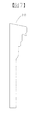
図7は本発明のさらに別の実施例で、建築用外装役物20は裏抜き部がなく、下端部分が長い幕板形状のものである。
作用効果は実施例1と同様である。
FIG. 7 shows still another embodiment of the present invention. The
The effect is the same as that of Example 1.
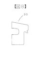
図8は本発明のさらに別の実施例で、建築用外装役物30は化粧表面の階段状がないものである。
作用効果は実施例1と同様である。
FIG. 8 shows still another embodiment of the present invention. The architectural
The effect is the same as that of Example 1.
本発明の建築用外装役物は、突出片にて雨水を前方斜め下にはじき飛ばすことが出来るので、開口部周りだけでなく、雨水の伝わりが気になる幕板部分や鼻隠し等にも使用することが出来る。 The building exterior accessory of the present invention can shed rain water forward and obliquely downward with a protruding piece, so not only around the opening, but also on the curtain plate part and nasal cover etc. Can be used.
1、10、20、30 建築用外装役物
2 傾斜辺
3 垂直辺
4 突出片
41 突出表面斜め辺
42 突出平坦辺
43 突出裏面斜め辺
44 表面側凹部
45 裏面側凹部
5 化粧表面
51 第1階段状凹部
52 第2階段状凹部
53 第3階段状凹部
54 第4階段状凹部
6 裏抜き部
101 窯業系外装材
102 縦胴縁
103 横胴縁
104 サッシ
105 バックアップ材
106 シ−リング材
107 釘
DESCRIPTION OF
Claims (2)
突出片は突出表面斜め辺と突出裏面斜め辺とその両辺に挟まれた突出平坦辺とからなり、前方斜め下に向かって幅が狭くなっており、上記垂直辺と突出表面斜め辺との間には表面側凹部が形成され、突出裏面斜め辺と化粧表面との間には裏面側凹部が形成されている建築用外装役物 In a building exterior accessory having an inclined side at the upper end and a vertical side connected to it, and a protruding piece having a vertex at a position substantially equivalent to the surface position of the vertical side at the lower end of the vertical side ,
The projecting piece is composed of a projecting surface oblique side, a projecting back surface oblique side, and a projecting flat side sandwiched between both sides, and has a narrow width toward the front obliquely lower side, between the vertical side and the projecting surface oblique side. A front side recess is formed on the front surface, and a back side recess is formed between the projecting back diagonal side and the decorative surface.
Priority Applications (1)
| Application Number | Priority Date | Filing Date | Title |
|---|---|---|---|
| JP2003290990A JP4377178B2 (en) | 2003-08-11 | 2003-08-11 | Architectural exterior |
Applications Claiming Priority (1)
| Application Number | Priority Date | Filing Date | Title |
|---|---|---|---|
| JP2003290990A JP4377178B2 (en) | 2003-08-11 | 2003-08-11 | Architectural exterior |
Publications (2)
| Publication Number | Publication Date |
|---|---|
| JP2005060995A JP2005060995A (en) | 2005-03-10 |
| JP4377178B2 true JP4377178B2 (en) | 2009-12-02 |
Family
ID=34368822
Family Applications (1)
| Application Number | Title | Priority Date | Filing Date |
|---|---|---|---|
| JP2003290990A Expired - Fee Related JP4377178B2 (en) | 2003-08-11 | 2003-08-11 | Architectural exterior |
Country Status (1)
| Country | Link |
|---|---|
| JP (1) | JP4377178B2 (en) |
Families Citing this family (1)
| Publication number | Priority date | Publication date | Assignee | Title |
|---|---|---|---|---|
| JP2012225047A (en) * | 2011-04-19 | 2012-11-15 | Lixil Corp | Hand-washing basin structure of hand-washing toilet bowl tank |
-
2003
- 2003-08-11 JP JP2003290990A patent/JP4377178B2/en not_active Expired - Fee Related
Also Published As
| Publication number | Publication date |
|---|---|
| JP2005060995A (en) | 2005-03-10 |
Similar Documents
| Publication | Publication Date | Title |
|---|---|---|
| US6311442B1 (en) | External corner formative member | |
| JP4377178B2 (en) | Architectural exterior | |
| JP4309746B2 (en) | Construction structure of fixing bracket and exterior material using this bracket | |
| JP4873941B2 (en) | Scattered sheet metal and roof structure | |
| JP7148358B2 (en) | roof structure | |
| JP4654159B2 (en) | Eaves tile | |
| JP3037267B2 (en) | Cosmetic materials for overhanging parts and windows around buildings | |
| JP4602525B2 (en) | Water stop structure of the outer wall joint | |
| JP4827708B2 (en) | Drainage device and drainage structure for outer wall | |
| JP2009019422A (en) | Shutter box | |
| JP3478779B2 (en) | Snow cover with hood | |
| JP2000136607A (en) | Cover member for eaves gutter | |
| JP3294578B2 (en) | Closed structure near the wall of handrail | |
| JP3843981B2 (en) | Rain dripping prevention structure | |
| JP3924117B2 (en) | Roof tile | |
| JPH0886164A (en) | Water drip tool | |
| JP3867090B2 (en) | Balcony structure with lattice | |
| JP2004353198A (en) | Raindrop preventive structure | |
| JP2008196221A (en) | Ventilation louver and blade therefof | |
| JP2005009197A (en) | Ventilation ridge | |
| JP2022138877A (en) | Tile roof | |
| JP3096439B2 (en) | Drainage structure of composite sash | |
| KR200232481Y1 (en) | Flashing device for window | |
| AU768469B2 (en) | A louvre blade | |
| JP2000045399A (en) | Flashing construction for opening |
Legal Events
| Date | Code | Title | Description |
|---|---|---|---|
| A621 | Written request for application examination |
Free format text: JAPANESE INTERMEDIATE CODE: A621 Effective date: 20060718 |
|
| A131 | Notification of reasons for refusal |
Free format text: JAPANESE INTERMEDIATE CODE: A131 Effective date: 20090707 |
|
| A521 | Written amendment |
Free format text: JAPANESE INTERMEDIATE CODE: A523 Effective date: 20090728 |
|
| TRDD | Decision of grant or rejection written | ||
| A01 | Written decision to grant a patent or to grant a registration (utility model) |
Free format text: JAPANESE INTERMEDIATE CODE: A01 Effective date: 20090908 |
|
| A01 | Written decision to grant a patent or to grant a registration (utility model) |
Free format text: JAPANESE INTERMEDIATE CODE: A01 |
|
| A61 | First payment of annual fees (during grant procedure) |
Free format text: JAPANESE INTERMEDIATE CODE: A61 Effective date: 20090910 |
|
| R150 | Certificate of patent or registration of utility model |
Free format text: JAPANESE INTERMEDIATE CODE: R150 |
|
| FPAY | Renewal fee payment (event date is renewal date of database) |
Free format text: PAYMENT UNTIL: 20120918 Year of fee payment: 3 |
|
| FPAY | Renewal fee payment (event date is renewal date of database) |
Free format text: PAYMENT UNTIL: 20120918 Year of fee payment: 3 |
|
| FPAY | Renewal fee payment (event date is renewal date of database) |
Free format text: PAYMENT UNTIL: 20130918 Year of fee payment: 4 |
|
| LAPS | Cancellation because of no payment of annual fees |