JP4355697B2 - Graphic model generation method and graphic model generation apparatus - Google Patents
Graphic model generation method and graphic model generation apparatus Download PDFInfo
- Publication number
- JP4355697B2 JP4355697B2 JP2005299609A JP2005299609A JP4355697B2 JP 4355697 B2 JP4355697 B2 JP 4355697B2 JP 2005299609 A JP2005299609 A JP 2005299609A JP 2005299609 A JP2005299609 A JP 2005299609A JP 4355697 B2 JP4355697 B2 JP 4355697B2
- Authority
- JP
- Japan
- Prior art keywords
- graphic model
- model
- edge
- vertices
- vertex
- Prior art date
- Legal status (The legal status is an assumption and is not a legal conclusion. Google has not performed a legal analysis and makes no representation as to the accuracy of the status listed.)
- Expired - Lifetime
Links
Images


Classifications
-
- G—PHYSICS
- G06—COMPUTING; CALCULATING OR COUNTING
- G06T—IMAGE DATA PROCESSING OR GENERATION, IN GENERAL
- G06T17/00—Three dimensional [3D] modelling, e.g. data description of 3D objects
- G06T17/20—Finite element generation, e.g. wire-frame surface description, tesselation
-
- G—PHYSICS
- G06—COMPUTING; CALCULATING OR COUNTING
- G06T—IMAGE DATA PROCESSING OR GENERATION, IN GENERAL
- G06T17/00—Three dimensional [3D] modelling, e.g. data description of 3D objects
- G06T17/20—Finite element generation, e.g. wire-frame surface description, tesselation
- G06T17/205—Re-meshing
-
- G—PHYSICS
- G06—COMPUTING; CALCULATING OR COUNTING
- G06T—IMAGE DATA PROCESSING OR GENERATION, IN GENERAL
- G06T2210/00—Indexing scheme for image generation or computer graphics
- G06T2210/36—Level of detail
Description
この発明は、CG(Computer Graphics) において使用される幾何モデルを、その形状の持つ複雑度を削減することによりデータ量を削減し、CGの描画を高速に行うことが可能な、グラフィックモデル生成方法およびグラフィックモデル生成装置に関する。また、この発明は、より違和感を覚えない方法で近似化した形状を変化させるようにされているため、CGを利用するゲームを始め、VR(Virtual Reality) 、デザインなどに用いて好適なグラフィックモデル生成方法およびグラフィックモデル生成装置に関する。 The present invention provides a graphic model generation method capable of reducing the amount of data of a geometric model used in CG (Computer Graphics) by reducing the complexity of the shape and drawing CG at high speed. And a graphic model generation apparatus . Further, the present invention is because it is so as to vary the approximate shape in a way that does not remember more uncomfortable, it started a game utilizing CG, VR (Virtual Reality), suitable graphics model using such a design The present invention relates to a generation method and a graphic model generation apparatus .
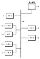
CGでモデルを使って描画を行う場合には、常に同一のモデルを使用するのが一般的である。例えば図14に示すように、100%のデータを有する詳細なオリジナルのモデルを作成し、これを使用してディスプレイ上でCGを描画する。画面の中でモデルが遠くに配置されて見かけ上は小さくなっても、同一のモデルを使用するためにモデルの詳細度は変わらない。このために、描画に要する時間は、モデルの詳細度とその数に負う。 When drawing using a model in CG, it is common to always use the same model. For example, as shown in FIG. 14, a detailed original model having 100% data is created, and this is used to draw a CG on the display. Even if the model is arranged far away on the screen and apparently becomes smaller, the details of the model do not change because the same model is used. For this reason, the time required for drawing depends on the level of detail and the number of models.
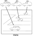
しかし、モデルが遠くに配置されたことにより画面上で小さくなったり、あるいは画面の注目点から外れたことにより観察者がそのモデルに注目しなくなった場合には、必ずしも同じ詳細度を持ったモデルを使った描画する必要が無くなる。つまり、モデルの持つ頂点数を減らしたりポリゴンの面数を減ずるなどの手法を用いてモデルの詳細度をある程度落とした、似たモデルを使用することで見かけ上は同一のモデルを使っているように見せることが可能である。この例を図15に示す。モデルが遠くに配置され、画面上での大きさが小さな場合には、例に示したように、オリジナルのモデルに対して、データが例えば50%,25%と削減され詳細度を落とされ近似化されたモデルを使用してCGの描画を行えば良い。このように、オリジナルモデルに比べてデータ量の少ないモデルを使用することによって、描画の高速化が図れる。 However, if the model becomes smaller on the screen due to the disposition of the model, or if the observer stops paying attention to the model because it is off the point of interest on the screen, the model does not necessarily have the same level of detail. There is no need to draw using. In other words, it seems that the same model is apparently used by using a similar model that reduces the level of detail of the model to some extent by reducing the number of vertices of the model or reducing the number of polygon faces. It is possible to show to. An example of this is shown in FIG. When the model is placed far away and the size on the screen is small, as shown in the example, the data is reduced to 50%, 25%, for example, and the degree of detail is reduced and approximated to the original model. The CG may be drawn using the model that has been made into a model. In this way, using a model with a smaller amount of data than the original model can speed up drawing.
上述したように、このようなモデルの近似化は、CGモデルの描画には有用なものである。しかしながら、モデルの詳細度を落とし近似化を行う際に、モデルのデータ量を単純に削減するだけでは観察者がこの近似化モデルを見た際に違和感を感じてしまう。この違和感を抑えることができれば、描画速度と描画品質の両方への要求を満足することができる。そのためには、モデルの持つ大局的な特徴部分を残し、それ以外の部分を削減しながらデータ量を減らすことが望ましい。このようなモデルの近似化は、従来では、多くはデザイナーの手作業によって行われており、この作業には多くの手間と時間が必要とされていた。 As described above, approximation of such a model is useful for drawing a CG model. However, when performing approximation by reducing the level of detail of the model, simply reducing the data amount of the model makes the observer feel uncomfortable when viewing the approximate model. If this sense of incongruity can be suppressed, the requirements for both the drawing speed and the drawing quality can be satisfied. For that purpose, it is desirable to reduce the amount of data while keeping the global characteristic part of the model and reducing the other parts. Conventionally, the approximation of such a model is often performed manually by a designer, and this work requires a lot of labor and time.
また、描画対象となるモデルのモデル面に対して2次元の画像を貼り付けて、よりリアルな映像を得ることが一般に行われている。これはテクスチャマッピングと称される。このときに貼り付けられる画像をテクスチャと称する。このテクスチャマッピングがなされたモデルに対して上述の形状の近似化を行う際には、モデル面に張られているテクスチャにも注意を払う必要がある。すなわち、近似化時に、テクスチャ形状の崩れによりモデルの見栄えが悪くなってしまうのを防いだり、近似化したモデルに再度テクスチャを貼り付けるために全体の作業量が増えるなどの弊害が起こらないようにする必要がある。 In addition, it is a common practice to obtain a more realistic image by pasting a two-dimensional image on the model surface of a model to be rendered. This is called texture mapping. The image pasted at this time is called a texture. When approximating the above-described shape to a model on which this texture mapping has been performed, it is necessary to pay attention to the texture stretched on the model surface. In other words, to prevent the appearance of the model from deteriorating due to the collapse of the texture shape at the time of approximation, and to avoid adverse effects such as increasing the overall work amount to paste the texture again on the approximated model There is a need to.
過去の研究において、Francis J.M.Schmitt, Brian A.Barsky, Wen-Hui Du による"An Adaptive Subdivision Method for Surface-Fitting from Sampled Data"(Computer Graphics Vol.20, No.4, August 1986) では、3次元の形状に対してベジエパッチを貼り付けて形状の近似を行っているが、一般的なポリゴンを対象としていないという問題がある。 In past research, "An Adaptive Subdivision Method for Surface-Fitting from Sampled Data" (Computer Graphics Vol.20, No.4, August 1986) by Francis JMSchmitt, Brian A. Barsky, Wen-Hui Du The shape is approximated by attaching a Bezier patch to this shape, but there is a problem that general polygons are not targeted.
また、Greg Turk による"Re-Tiling Polygonal Surface"(Computer GraphicsVol.26, No.2, July 1992) では、ポリゴンモデルを階層的に近似する試行を行っている。しかし、この論文におけるアルゴリズムは、丸みを帯びた形状には適用できるが、角張った形状には適さない問題点があり、一般的な形状を対象としていない。さらに物体形状の特徴点を元に形状を近似化することを考慮してない。 Also, "Re-Tiling Polygonal Surface" by Greg Turk (Computer GraphicsVol.26, No.2, July 1992) tries to approximate the polygon model hierarchically. However, although the algorithm in this paper can be applied to a rounded shape, it has a problem that it is not suitable for an angular shape, and does not target a general shape. Furthermore, the approximation of the shape based on the feature points of the object shape is not considered.
さらに、Hugues Hoppeらによる"Mesh Optimization"(Computer Graphics Proceedings, Annual Conference Series, SIGGRAPH 1993) では、近似化モデルの評価にエネルギーを導入し、このエネルギーを最小とするようにエッジの除去、パッチの分割、エッジのスワップを繰り返してモデルを近似化している。しかし、この論文の手法では、エネルギーの最小点を見いだすまでに長い反復計算を必要とするばかりでなく、局所的な最小点に陥らないために、他のエネルギー最小問題と同様にsimulated annealing などの解決手法を必要とする。またエネルギー最小点が必ずしも視覚的に最良となる保証もない。 In addition, "Mesh Optimization" by Hugues Hoppe et al. (Computer Graphics Proceedings, Annual Conference Series, SIGGRAPH 1993) introduces energy into the evaluation of approximation models, removes edges and splits patches to minimize this energy. The model is approximated by repeated swapping of edges. However, the method of this paper not only requires a long iterative calculation to find the minimum point of energy, but also does not fall into a local minimum point. Need a solution. Also, there is no guarantee that the energy minimum will be visually best.
さらにまた、これらの論文においては、近似化時に、モデルに貼り付けたテクスチャまでは考慮されていない。このため、これらの論文による方法でのモデルの近似化では、近似化後にテクスチャを改めて近似化モデルに貼り付けるというように、2重の処理が必要になるという問題点があった。 Furthermore, in these papers, the texture pasted on the model is not taken into consideration at the time of approximation. For this reason, in the approximation of the model by the methods according to these papers, there is a problem that a double process is required, such that a texture is pasted to the approximated model after the approximation.
このように、過去における研究では、ポリゴン描画の際のモデル近似化に対して問題を含んでいた。すなわち、従来の方法においては、形状近似化の適用が限定されている、近似化のために長い計算時間が必要とされる、また大局的に必要な特徴点を考慮した近似化が行われていないなどといった問題点があった。また、近似化モデルの切り替え時における観察者に与える違和感を考慮に入れた、連続的な階層の切り替えを実現するための図形データの近似化も行われていなかった。 As described above, in past research, there was a problem with model approximation in polygon drawing. That is, in the conventional method, application of shape approximation is limited, long calculation time is required for approximation, and approximation considering globally necessary feature points is performed. There was a problem such as not. Further, there has been no approximation of graphic data for realizing continuous hierarchy switching, taking into account the uncomfortable feeling given to the observer when switching the approximation model.
また、テクスチャが貼り付けられた幾何モデルに対して近似化を行なう際に、モデルに貼り付けたテクスチャの形状保存を行い、近似化後の品質劣化を防ぐことが行われていないという問題点があった。また、近似化後に改めてテクスチャを貼り付ける必要を無くすといった対策が取られていないという問題点があった。さらに、テクスチャそのものの存在を考慮した近似化が行われていないという問題点があった。 In addition, when approximating a geometric model to which texture is pasted, the shape of the texture pasted on the model is saved and quality degradation after approximation is not prevented. there were. Further, there has been a problem that no countermeasure has been taken to eliminate the need for pasting a texture after approximation. Furthermore, there is a problem that the approximation considering the existence of the texture itself is not performed.
したがって、この発明の目的は、CGの描画において、描画品質を維持しながら高速な描画を行うような、グラフィックモデル生成方法およびグラフィックモデル生成装置を提供することにある。 Accordingly, an object of the present invention is to provide a graphic model generation method and a graphic model generation apparatus that perform high-speed drawing while maintaining drawing quality in CG drawing.
また、この発明の目的は、テクスチャそのものの存在を考慮した上で、幾何モデルの近似化を行なうような、グラフィックモデル生成方法およびグラフィックモデル生成装置を提供することにある。 Another object of the present invention is to provide a graphic model generation method and a graphic model generation apparatus that approximate a geometric model in consideration of the presence of the texture itself.
この発明は、上述した課題を解決するために、複数の頂点と頂点間に形成されるエッジと複数の前記エッジで規定される面とを有するオリジナルのグラフィックモデルに対し頂点を順次統合する近似化を施して得られた近似化グラフィックモデルから、よりオリジナルに近いグラフィックモデルを生成するグラフィックモデル生成方法であって、所望の階層のグラフィックモデルの統合された1つの頂点と、統合された1つの頂点に対応する別の階層の統合前の2つの頂点の情報とから、補間する階層の新たな2つの頂点の位置と生成された頂点間のエッジを決定するステップをコンピュータに実行させるグラフィックモデル生成方法である。 In order to solve the above-described problem, the present invention provides an approximation in which vertices are sequentially integrated into an original graphic model having a plurality of vertices, edges formed between the vertices, and a surface defined by the plurality of edges. Is a graphic model generation method for generating a graphic model closer to the original from the approximated graphic model obtained by applying the integrated one vertex of the graphic model of the desired hierarchy and the one integrated vertex Graphic model generation method for causing a computer to execute the step of determining the position of two new vertices in the layer to be interpolated and the edge between the generated vertices from the information of the two vertices before integration of another layer corresponding to It is.
また、この発明は、上述した課題を解決するために、複数の頂点と頂点間に形成されるエッジと複数の前記エッジで規定される面とを有するオリジナルのグラフィックモデルに対し頂点を順次統合する近似化を施して得られた近似化グラフィックモデルから、よりオリジナルに近いグラフィックモデルを生成するグラフィックモデル生成装置であって、所望の階層のグラフィックモデルの統合された1つの頂点と、統合された1つの頂点に対応する別の階層の統合前の2つの頂点の情報とから、補間する階層の新たな2つの頂点の位置と生成された頂点間のエッジを決定するグラフィックモデル生成装置である。 In order to solve the above-described problems, the present invention sequentially integrates vertices with respect to an original graphic model having a plurality of vertices, edges formed between the vertices, and a surface defined by the plurality of edges. from approximated graphic model obtained by subjecting the approximation, a graphic model generating device for generating a more graphic model close to the original, and one vertex that is integrated in the desired hierarchy graphic models, integrated 1 This is a graphic model generation device that determines the positions of two new vertices in the layer to be interpolated and the edge between the generated vertices from the information of the two vertices before integration of another layer corresponding to one vertex .
上述したように、この発明は、複数の頂点と頂点間に形成されるエッジと複数のエッジで規定される面とを有するオリジナルのグラフィックモデルに対し頂点を順次統合する近似化を施して得られた近似化グラフィックモデルから、よりオリジナルに近いグラフィックモデルを生成する場合において、近似化の際に統合された頂点の情報に基づいて、近似化グラフィックモデルの1つの頂点から2つの頂点を生成するようにしているために、形状データの近似化を、形状モデルに貼り付けられた画像データを崩れを押さえつつ、形状の変化が少ないように行なうことができる。 As described above, the present invention is obtained by applying an approximation that sequentially integrates vertices to an original graphic model having a plurality of vertices, an edge formed between the vertices, and a surface defined by the plurality of edges. When generating a graphic model that is closer to the original from the approximated graphic model, two vertices are generated from one vertex of the approximated graphic model based on the vertex information integrated at the time of approximation. for you are in, the approximation of the shape data, while suppressing the collapse of the image data pasted to the shape model can be performed such that the change in shape is small.
この発明によれば、CGに使用する例えばポリゴンデータといった幾何データに対して画像データ(テクスチャ)を貼り付けた場合、テクスチャ形状の崩れや見た目の品質悪化を防ぎながら所望の詳細度に近似化することが可能となる。またモデルを近似化した後に改めてテクスチャを貼り付ける手間も省くことができる。 According to the present invention, when image data (texture) is pasted on geometric data such as polygon data used for CG, it is approximated to a desired level of detail while preventing deformation of the texture shape and deterioration of visual quality. It becomes possible. Also, it is possible to save the trouble of pasting the texture again after approximating the model.
したがって、この発明によれば、CGに使用する幾何モデルを、テクスチャを貼り付けた状態で近似化することができる効果がある。また、単に近似化するだけでなく、近似化結果におけるテクスチャの形状崩れを抑えることができる効果がある。 Therefore, according to the present invention, there is an effect that a geometric model used for CG can be approximated with a texture attached. Further, there is an effect that not only the approximation but also the texture shape collapse in the approximation result can be suppressed.
また、この発明に基づく方法によって近似化した幾何モデルを使用することにより、CGの描画において、高速かつ高画質での描画の要求を満たすことが可能となる効果がある。 Further, by using the geometric model approximated by the method according to the present invention, there is an effect that it is possible to satisfy the demand for drawing at high speed and high image quality in CG drawing.
さらに、この発明によれば、CGに使用する幾何モデルを構成する各エッジの重要度を評価値によって評価することができる。そして、このエッジの評価値が低いエッジを優先的に除去することによって幾何モデルの近似化を行うことができる効果がある。 Furthermore, according to the present invention, the importance of each edge constituting the geometric model used for CG can be evaluated by the evaluation value. Then, there is an effect that the geometric model can be approximated by preferentially removing edges with low edge evaluation values.
また、この発明によれば、大局的な形状の変化を抑えるように、エッジを除去した後に残る頂点の位置を決定することができる。これにより、近似化したモデルを使って描画する際の見た目の違和感を抑えることができる効果がある。 Further, according to the present invention, the position of the vertex remaining after removing the edge can be determined so as to suppress the change in the global shape. As a result, there is an effect that it is possible to suppress an uncomfortable appearance when drawing using the approximated model.
また、この発明によれば、CGで使用する図形データを複数の解像度で近似化することが可能であり、この発明によって得られた図形データを使うことによって、高速描画と高品質描画とを同時に満足することができる効果がある。 Further, according to the present invention, it is possible to approximate graphic data used in CG with a plurality of resolutions. By using the graphic data obtained by the present invention, high-speed drawing and high-quality drawing can be performed simultaneously. There is an effect that can be satisfied.
以下、この発明の実施の一形態を、図面を参照しながら説明する。図1は、この発明による、テクスチャマッピングされた幾何(ポリゴン)モデルの階層的近似化のフローチャートを示す。また、図2は、このフローチャートを実行可能な描画装置の構成の一例を示す。 Hereinafter, an embodiment of the present invention will be described with reference to the drawings. FIG. 1 shows a flow chart for hierarchical approximation of a texture mapped geometric (polygon) model according to the present invention. FIG. 2 shows an example of the configuration of a drawing apparatus that can execute this flowchart.
図2に示されるように、この描画装置は、キーボード1,フレキシブルディスクドライブ(FDD)2,光磁気ディスク(MO)ドライブ3などのデータ入力デバイス、CPU4やRAM5などによるデータ処理装置,ハードディスク6や半導体メモリ7などの外部記憶装置、およびCRTなどによる表示装置8などから成り、これらのそれぞれがバス9によって互いに接続された、標準的な構成のコンピュータによって構成することができる。なお、入力デバイスとしては、他にマウスなども用いられ、また、フレキシブルディスクドライブ2,MOドライブ3は、データ出力デバイスとしても用いられる。さらに、インターネットなどのネットワークからデータの供給を行なうようにすることもできる。なお、この構成は一例であって、実際の描画装置の構成は種々可能である。
As shown in FIG. 2, the drawing apparatus includes a data input device such as a
先ず、図1に示されるフローチャートにおける処理について、概略的に説明する。ポリゴンの各面には、画像データであるテクスチャが割り当てられ貼り付けられる。この発明においては、このポリゴンの近似化を行うために、ポリゴンを構成するエッジの除去を行い、その形状を近似化する。このエッジの除去だけではポリゴンの形状が近似化されるだけであるため、ポリゴンの各面に割り当てられたテクスチャの近似化を行なうために、エッジ除去に伴ったテクスチャの統合とテクスチャ座標の移動による最適化がなされる。 First, the process in the flowchart shown in FIG. 1 will be schematically described. A texture, which is image data, is assigned and pasted to each surface of the polygon. In the present invention, in order to approximate the polygon, the edges constituting the polygon are removed and the shape is approximated. Since the removal of the edge only approximates the shape of the polygon, in order to approximate the texture assigned to each face of the polygon, it is possible to integrate the texture and move the texture coordinates along with the edge removal. Optimization is done.
最初のステップS1において、オリジナルのポリゴンデータの入力が行われる。そして、この入力されたポリゴンデータに対して、各面にテクスチャが貼り付けられる。このデータの入力およびテクスチャの貼り付けは、キーボード1から人手によって、あるいは、他所で作成されフレキシブルディスクやMOディスクに記憶されたデータがFDD2やMOドライブ3において読み出されることによって行われる。また、このポリゴンデータの入力は、例えばインターネットといった、ネットワークを介して行なうようにもできる。
In the first step S1, original polygon data is input. Then, a texture is pasted on each surface of the input polygon data. This data input and texture pasting are performed manually from the
次のステップS2では、入力されたポリゴンデータについて、エッジ除去を行うための各エッジの評価が行われる。このステップS2でのエッジ評価において、入力されたポリゴンデータにおける各エッジが後述する方法によってそれぞれ数値化され評価値とされる。そして、次のステップS3において、ステップS2において得られた各エッジの評価値に対してソートが行われ、評価値が最小であるエッジが選択される。そして、処理はステップS4に移行する。ステップS4では、ステップS3で選択された、評価値が最小のエッジの除去が行われる。 In the next step S2, evaluation of each edge for performing edge removal is performed on the input polygon data. In the edge evaluation in step S2, each edge in the input polygon data is digitized by the method described later to be an evaluation value. Then, in the next step S3, sorting is performed on the evaluation value of each edge obtained in step S2, and an edge having the smallest evaluation value is selected. Then, the process proceeds to step S4. In step S4, the edge having the smallest evaluation value selected in step S3 is removed.
ステップS4においてエッジの除去が行われると、処理は次のステップS5に移行する。このステップS5では、ステップS4でエッジが除去された後に残る頂点の位置が決定される。そして、ステップS6で、エッジ除去に伴って不要になったテクスチャ部分の除去および残ったテクスチャ座標の位置決定が行なわれる。 When edge removal is performed in step S4, the process proceeds to the next step S5. In step S5, the position of the vertex remaining after the edge is removed in step S4 is determined. Then, in step S6, the removal of the texture portion that has become unnecessary due to the edge removal and the position determination of the remaining texture coordinates are performed.
上述のステップS2からこのステップS6までの処理で、1段階の精度で近似化された、テクスチャマッピングされた近似化ポリゴンデータが得られる。このステップS2からステップS6までの処理を繰り返し実行し、エッジの除去および新しい頂点の決定、ならびにこれらの伴うテクスチャの処理を重ねることによって、所望の精度で、テクスチャマッピングされた近似化ポリゴンデータを得ることができる。 By the processing from step S2 to step S6 described above, approximated polygon data subjected to texture mapping, which is approximated with one level of accuracy, is obtained. The process from step S2 to step S6 is repeatedly executed, and the removal of edges and determination of new vertices, and the processing of the accompanying textures are repeated, thereby obtaining approximate polygon data subjected to texture mapping with desired accuracy. be able to.
ステップS6において、所望の精度のテクスチャマッピングされた近似化ポリゴンデータが得られたとされれば(ステップS7)、処理はステップS8に移行し、この得られたテクスチャマッピングされた近似化ポリゴンデータの表示装置8に対する描画が行われる。また、それと共に、得られたテクスチャマッピングされた近似化ポリゴンデータを、ハードディスク6やメモリ7といった外部記憶装置、FDD2に挿入されたフレキシブルディスクやMOドライブ3に挿入されたMOに対して記憶させるようにしてもよい。さらに、得られたデータを、ネットワークを介して他のコンピュータシステムに対して供給し、記憶させるようにもできる。
If it is determined in step S6 that approximated polygon data having desired texture mapping has been obtained (step S7), the process proceeds to step S8, and the obtained approximated polygon data subjected to texture mapping is displayed. Drawing on the
以上のフローチャートの処理は、図2のハードウェア構成においてCPU4を中心に行われ、また、処理の中途で必要となる指示などは、キーボード1などからなる入力デバイスからCPU4に対して行われる。
The processing of the above flowchart is performed mainly by the
先ず、まずモデル近似化に関わる処理について説明する。上述したように、ポリゴンモデルの近似は、エッジ除去の繰り返しによって実行される。このとき、モデルが持つ大局的な形状に寄与しない小さな凹凸成分を判断し、この判断に基づき、どのエッジを優先的に除去すべきかの決定がなされる。この、優先的に除去するエッジの選択のために、モデルを構成する各エッジがどれくらい大局的な形状に寄与するか、すなわちエッジの重要度の評価を行い、この評価値が小さなエッジから除去が行われる。ステップS2において、このエッジの重要度の評価が行われる。 First, processing related to model approximation will be described. As described above, the approximation of the polygon model is executed by repeating edge removal. At this time, a small concavo-convex component that does not contribute to the global shape of the model is determined, and based on this determination, which edge should be preferentially removed is determined. In order to select edges to be preferentially removed, the global shape of each edge constituting the model contributes to the shape of the edge, that is, the importance of the edge is evaluated. Done. In step S2, the importance of the edge is evaluated.
この評価値を得、除去に適したエッジを選択するために、ポリゴンモデルを構成するエッジのそれぞれがどれ程このポリゴンモデルの形状に寄与しているかを評価する評価関数を導入する。数式(1)にこの評価関数の一例を示し、図3にこの数式(1)を説明するための図を示す。 In order to obtain this evaluation value and select an edge suitable for removal, an evaluation function for evaluating how much each of the edges constituting the polygon model contributes to the shape of the polygon model is introduced. An example of this evaluation function is shown in Formula (1), and a diagram for explaining Formula (1) is shown in FIG.

図3Aに示される、各面が三角形で構成された球状のポリゴンモデルの一部を拡大した例が図3Bである。数式(1)は、2頂点v1 ,v2 から構成されるエッジeを評価する。ここで、エッジe(v1 ,v2 )を構成する2頂点v1 ,v2 について、これらを頂点として含む面の集合をS(v1 ),S(v2 )とした場合、iの範囲は、S(v1 )∪S(v2 )となる。すなわち、この図3Bに示された例では、1≦i≦10とされる。また、Eはエッジeの向きと長さを持つベクトル、Ni は各面の単位法線ベクトル、Ai は面の面積、|E|はベクトルEの長さをそれぞれ示す。 FIG. 3B shows an example in which a part of a spherical polygon model in which each surface is formed of a triangle shown in FIG. 3A is enlarged. Equation (1) evaluates an edge e composed of two vertices v 1 and v 2 . Here, regarding the two vertices v 1 and v 2 constituting the edge e (v 1 , v 2 ), when a set of surfaces including these vertices as S (v 1 ) and S (v 2 ), The range is S (v 1 ) ∪S (v 2 ). That is, in the example shown in FIG. 3B, 1 ≦ i ≦ 10. Moreover, E is a vector having the direction and length of the edge e, N i is the unit normal vector of each surface, the area of the A i the surface, | indicate the length of the vector E, respectively | E.
数式(1)は、2つの項からなり、第1項Vi は、評価対象となるエッジを除去した場合に変化する体積量を表す。なお、ここでの体積量とは、ポリゴンの形状データで規定される形状の仮想的な体積をいう。第2項Si は、対象エッジの両脇に存在する面と対象エッジの長さを乗算した値である。これは対象エッジだけを含んだ面の体積変化分を意味する。これらの2つの項には、a,bの係数がそれぞれかけられており、ユーザは、これらの係数の大小を適当に設定することによって、第1項V1 および第2項Si の何方の項を優先するかを選択することができる。 Formula (1) consists of two terms, and the first term V i represents the volume that changes when the edge to be evaluated is removed. Here, the volume amount means a virtual volume of a shape defined by polygon shape data. The second term S i is a value obtained by multiplying the surface existing on both sides of the target edge by the length of the target edge. This means the volume change of the surface including only the target edge. These two terms are respectively multiplied by the coefficients a and b, and the user can set which one of the first term V 1 and the second term S i by appropriately setting the magnitude of these coefficients. You can choose whether to prioritize terms.
第1項のVi は、評価対象となるエッジの周辺形状に大きく依存する。一方、第2項のSi は、対象エッジの長さとその両脇に存在する面の面積に依存する。モデル形状が一枚の紙のようにフラットな形状のポリゴンモデルでは、エッジe(v1 ,v2 )を除去した場合、Vi よりもSi の項による変化量が大きい。また全ての面が同じような形状と面積の面で構成されているポリゴンモデル、例えば図3Aに示されたモデルでは、Si よりもVi の項による変化量が大きくなる。 V i in the first term greatly depends on the peripheral shape of the edge to be evaluated. On the other hand, S i of the second term depends on the length of the target edge and the area of the surface existing on both sides thereof. In a polygon model having a flat model shape like a sheet of paper, when the edge e (v 1 , v 2 ) is removed, the amount of change due to the term of S i is larger than V i . In addition, in a polygon model in which all the surfaces are configured with surfaces having the same shape and area, for example, the model shown in FIG. 3A, the amount of change due to the term V i is larger than S i .
ポリゴンモデルを構成する各エッジについてこの数式(1)の値を計算し、各エッジに対する評価値をそれぞれ得る。次のステップS3において、その計算値を大きさの順にソートして最も小さな評価値のエッジを選択することによって、エッジ除去時のモデル形状への寄与が最小のエッジが得られる。 The value of Equation (1) is calculated for each edge constituting the polygon model, and an evaluation value for each edge is obtained. In the next step S3, the calculated values are sorted in order of size, and the edge having the smallest evaluation value is selected, whereby an edge having the smallest contribution to the model shape at the time of edge removal is obtained.
また、このステップS2におけるエッジの重要度の評価の際に、エッジの長さも考慮して、評価値が同じ場合にはエッジの長さが小さな方から除去対象とするようにしてもよい。 In addition, when evaluating the importance of the edge in step S2, the length of the edge may be taken into consideration, and if the evaluation value is the same, the edge may be removed from the smaller edge.
なお、数式(1)は、ポリゴンモデルにおける局所的な評価値であるが、ある注目エッジの評価値に対して、その周辺エッジの評価値を加えた値で、各エッジを評価することもできる。この場合は、1つのエッジ周辺形状のみならず、より広範囲な形状で評価をすることができる。このように使用者の評価したい領域が広ければ、その領域に従って数式(1)の計算範囲を広げることができる。 Equation (1) is a local evaluation value in the polygon model, but each edge can also be evaluated with a value obtained by adding an evaluation value of a peripheral edge to an evaluation value of a certain target edge. . In this case, it is possible to evaluate not only one edge peripheral shape but also a wider range of shapes. Thus, if the area that the user wants to evaluate is large, the calculation range of the formula (1) can be expanded according to the area.
また、単に数式(1)の計算による評価値だけでなく、使用者が評価値を与えたり、あるいは評価値の大小を操作することもできる。したがって、使用者が形状の中で残したい部分や、逆に早く近似化したい部分がある場合、その部分を指定して近似化の処理にデザイナやオペレータの意向を反映することが可能となる。この場合、使用者の操作した値と計算された評価値とにそれぞれ重み付け係数を与え、重み付き加算を行い評価値の決定を行う。 Further, not only the evaluation value based on the calculation of Expression (1), but also the user can give the evaluation value or manipulate the magnitude of the evaluation value. Therefore, if there is a part that the user wants to leave in the shape or a part that the user wants to approximate quickly, the part can be specified and the intention of the designer or operator can be reflected in the approximation process. In this case, a weighting coefficient is given to the value operated by the user and the calculated evaluation value, respectively, and weighted addition is performed to determine the evaluation value.
この場合、重み付け係数の与え方により、例えば使用者が指定した評価値に大きな重みを与えることによって、よりデザイナの意図を強く反映する近似化を行うことができる。逆に、数式(1)の計算による評価値に大きな重みをおけば、形状の体積変化の定量的評価により忠実な近似化を行うことができる。このように、重み付けによって自由に形状の変化を制御することが可能である。 In this case, approximation that strongly reflects the intention of the designer can be performed by giving a large weight to the evaluation value designated by the user, for example, by giving the weighting coefficient. On the contrary, if a large weight is given to the evaluation value obtained by the calculation of Equation (1), a faithful approximation can be performed by quantitative evaluation of the volume change of the shape. In this way, it is possible to freely control the change in shape by weighting.
このように、ステップS2においてポリゴンデータの各エッジに対する評価値がそれぞれ得られると、次のステップS3において、得られた評価値に対してソートが行われ、最小の評価値を有するエッジが選び出される。このエッジのソートには、例えば既知の技術であるクイックソートを利用することができる。勿論、他のソート方法を用いてもよい。この、クイックソートをはじめとするソート方法は、例えば、共立出版株式会社刊の「アルゴリズム辞典」などに詳しく解説されているために、ここではその説明を省略する。そして、次のステップS4において、選び出された最小の評価値を有するエッジの除去が行われる。 As described above, when the evaluation value for each edge of the polygon data is obtained in step S2, the obtained evaluation value is sorted in the next step S3, and the edge having the minimum evaluation value is selected. It is. For example, quick sorting, which is a known technique, can be used for sorting the edges. Of course, other sorting methods may be used. This sort method including quick sort is described in detail in, for example, “Algorithm Dictionary” published by Kyoritsu Publishing Co., Ltd., and the description thereof is omitted here. In the next step S4, the selected edge having the smallest evaluation value is removed.
なお、ここでは、単純に評価値が最小のエッジを除去する例を説明したが、エッジ除去の順番や除去しないエッジを任意に指定するようにしてもよい。エッジを除去しない場合には、その部分の形状変化がない。例えば2つのモデルが接する部分などのように、形状が変化しない方が望ましい場合には、エッジを除去しない部分を設定すればよい。 Here, an example has been described in which the edge with the smallest evaluation value is simply removed, but the order of edge removal and the edges that are not to be removed may be arbitrarily designated. When the edge is not removed, there is no change in the shape of the portion. For example, when it is desirable that the shape does not change, such as a portion where two models are in contact, a portion where the edge is not removed may be set.
ステップS4でエッジの除去が行われると、そのエッジを構成していた頂点(この例ではv1 ,v2 )が喪失される。そのため、次のステップS5において、エッジ除去に伴う新たな頂点位置の決定がなされる。図4は、この頂点位置決定の一例について示す。エッジを除去した後には、エッジを構成していた2つの頂点のうち何れか残される。この例では、図4Aの階層Nにおけるエッジe(v1 ,v2 )が除去され、図4Bに示す階層N+1とされ、頂点v1 が残され新たな頂点v’とされる。 When the edge is removed in step S4, the vertices (v 1 and v 2 in this example) constituting the edge are lost. Therefore, in the next step S5, a new vertex position associated with edge removal is determined. FIG. 4 shows an example of this vertex position determination. After the edge is removed, one of the two vertices constituting the edge is left. In this example, the edge e (v 1 , v 2 ) in the hierarchy N in FIG. 4A is removed, resulting in the hierarchy N + 1 shown in FIG. 4B, leaving the vertex v 1 as a new vertex v ′.
このとき、残される頂点v1 を何処の位置に置くかによって、エッジ除去後の形状が変化する。図5は、この残される頂点を置く位置を決定する方法の一例について示す。なお、この図5では、ポリゴンデータにおけるエッジ形状の断面を示している。すなわち、図5Aは、頂点v1 およびv2 で構成されるエッジe(v1 ,v2 )がv1 およびv2 の外側のエッジに対して凸型に形成されている場合を示し、図5Bは、エッジe(v1 ,v2 )がv1 およびv2 の外側のエッジに対して上下から挟まれS字型に形成されている場合を示す。また、図5Aおよび図5Bにおいて、頂点v’は、残される頂点を示す。 At this time, the shape after the edge removal changes depending on where the remaining vertex v 1 is placed. FIG. 5 shows an example of a method for determining the position to place the remaining vertex. FIG. 5 shows a cross section of the edge shape in the polygon data. That is, FIG. 5A shows a case where an edge e (v 1 , v 2 ) composed of vertices v 1 and v 2 is formed in a convex shape with respect to edges outside v 1 and v 2 . 5B shows a case where the edge e (v 1 , v 2 ) is sandwiched from above and below with respect to the outer edges of v 1 and v 2 and formed in an S shape. Moreover, in FIG. 5A and FIG. 5B, vertex v 'shows the vertex which remains.
これら図5Aおよび図5Bにおいて、斜線で示した領域S1 およびS2 は、エッジe(v1 ,v2 )が除去され頂点v’が残された場合の、体積変化分を示している。エッジe(v1 ,v2 )除去後に残される頂点v’の位置は、頂点v1 側での体積変化量S1 と、頂点v2 側での体積変化量S2 とが等しくなる位置に配置される。このように、除去されたエッジe(v1 ,v2 )の両側の体積変化量が等しくなる位置に頂点を配置することで、エッジ除去後の形状をよりオリジナルの形状に近付けることが可能となる。 In these FIG. 5A and FIG. 5B, regions S 1 and S 2 indicated by hatching indicate the volume change when the edge e (v 1 , v 2 ) is removed and the vertex v ′ is left. Position of the edge e (v 1, v 2) vertices left after removal v 'is the volume change amount S 1 of the vertex v 1 side, the volume change amount S 2 and are equal positions in the vertex v 2 side Be placed. In this way, by arranging the vertices at positions where the volume changes on both sides of the removed edge e (v 1 , v 2 ) are equal, the shape after the edge removal can be made closer to the original shape. Become.
なお、上述の説明では、ステップS5において、除去するエッジ周辺の形状に関係なく、エッジの両端側における体積変化量がそれぞれ等しくなる位置に、残され新たな頂点とされる頂点v’を配置したが、これはこの例に限定されるものではない。例えば、エッジ除去時の体積変化が最小になる位置に、頂点v’を配置するようにしてもよい。このように、エッジ両端側における体積変化量が等しくなるような位置に頂点v’を配置する方法と、体積変化が最小になる位置に、頂点v’を配置する方法とを、使用者の要望に従い使い分けることができる。 In the above description, in step S5, the vertex v ′ that is left as a new vertex is arranged at a position where the volume change amounts at both ends of the edge are equal, regardless of the shape around the edge to be removed. However, this is not limited to this example. For example, the vertex v ′ may be arranged at a position where the volume change at the time of edge removal is minimized. In this way, the user desires a method of arranging the vertex v ′ at a position where the volume change amounts at both ends of the edge are equal and a method of arranging the vertex v ′ at a position where the volume change is minimized. It can be used properly according to.
また、エッジ周辺の形状を考慮して、形状が凹型あるいは凸型の場合には、エッジ除去後の体積変化が最小になる位置に頂点を配置し、S字型の場合には、エッジ両端側の体積変化量が等しくなる位置に配置するようにしてもよい。この場合には、頂点v’の位置は、凹型および凸型の場合ではエッジの両端のどちらかに寄ることになるが、S字型の場合にはS字の中間に配置されることになる。したがって、体積変化を抑える効果とS字のような連続した変化を面で吸収する効果とを合わせ持つようにすることができる。 In consideration of the shape around the edge, when the shape is concave or convex, the vertex is arranged at the position where the volume change after the edge removal is minimized, and when the shape is S-shaped, both ends of the edge You may make it arrange | position in the position where volume change amount of becomes equal. In this case, the position of the vertex v ′ is closer to either end of the edge in the case of the concave shape and the convex shape, but in the case of the S shape, it is arranged in the middle of the S shape. . Therefore, it is possible to have both the effect of suppressing the volume change and the effect of absorbing the continuous change such as S-shape on the surface.
例えば、鋸の歯のように小さなS字型の変化が続く領域では、大局的な形状では1つの面で近似化することが可能となるうえ、S字型以外の大きな変化部分は、元の形状により近い形で近似化できる。形状を優先した近似化では、このような設定を行うこともでき、使用者の意図に従って近似化の方法を使い分けることが可能である。 For example, in a region where a small S-shaped change continues like a saw tooth, a global shape can be approximated by one surface, and a large change part other than the S-shape is It can be approximated by a shape closer to the shape. In the approximation with priority on the shape, such a setting can also be performed, and the approximation method can be properly used according to the intention of the user.
また、エッジ除去後に残る頂点位置を、エッジ除去以前の頂点位置から全く変化させないことも可能である。すなわち、上述の図4に示される例では、エッジe(v1 ,v2 )が除去された後に、例えば頂点v1 だけを除去前と位置を変えずに新たな頂点v’として残す。これは、注目している頂点が他のモデルとの接点に存在するなどで、その位置をずらさない方が望ましいような場合、有効な手段とされる。 It is also possible to keep the vertex position remaining after edge removal from the vertex position before edge removal at all. That is, in the example shown in FIG. 4 described above, after the edge e (v 1 , v 2 ) is removed, for example, only the vertex v 1 is left as a new vertex v ′ without changing its position. This is an effective means when it is desirable not to shift the position because the vertex of interest exists at the point of contact with another model.
ステップS5まででエッジの評価,除去,およびエッジの除去に伴う新たな頂点の決定がなされると、次のステップS6で、ポリゴンモデルの各面に貼り付けられたテクスチャに関する処理が行なわれる。図6は、ポリゴンモデル上のある面に画像データ(テクスチャ)を割り当てた例を模式的に示す。図6Aは、頂点v1 〜v8 からなるポリゴンモデルそのものを示し、左側の図に示されるモデルから、点線で示されるエッジe(v3 ,v6 )を除去すると、右側の図に示される形状に近似化されることを示す。図6Bは、図6Aに示されるポリゴンモデルに対してテクスチャが貼り付けられた様子を示す。ここでは、理解に容易なように、人物画に基づく画像データがテクスチャとして用いられている。図6B中の各座標vt1 〜vt8 は、図6Aにおける頂点v1 〜v8 にそれぞれ対応する。したがって、左側の図での各座標vt1 〜vt8 が図6Aにおけるエッジe(v3 ,v6 )除去に伴い右側に示される図のようになることを示す。 When the edge evaluation, removal, and determination of a new vertex associated with the removal of the edge are performed up to step S5, processing relating to the texture pasted on each surface of the polygon model is performed in the next step S6. FIG. 6 schematically shows an example in which image data (texture) is assigned to a certain surface on the polygon model. FIG. 6A shows the polygon model itself composed of vertices v 1 to v 8, and is shown in the right diagram when the edge e (v 3 , v 6 ) indicated by the dotted line is removed from the model shown in the left diagram. Indicates that the shape is approximated. FIG. 6B shows a state in which a texture is attached to the polygon model shown in FIG. 6A. Here, image data based on a person image is used as a texture for easy understanding. Each coordinate vt 1 ~vt in FIG 6B 8 correspond respectively to the vertex v 1 to v 8 in Figure 6A. Therefore, it is shown that the coordinates vt 1 to vt 8 in the left diagram are as shown in the diagram on the right side when the edge e (v 3 , v 6 ) is removed in FIG. 6A.
ポリゴンモデルの近似化により頂点v6 が除去され、このモデルにおける2つの頂点v3 およびv6 が1つの頂点v3 に統合される。これに伴い、v3 およびv6 とからなるエッジe(v3 ,v6 )を除去すれば、このエッジを含む両側の三角形の領域が喪失される。このとき、これらの三角形の領域の喪失を考慮しないと、テクスチャ座標vt3 ,vt4 ,vt6 からなる画像データと、vt3 ,vt5 ,vt6 からなる画像データとが喪失されることになる。 The vertex v 6 is removed by approximation of the polygon model, and the two vertices v 3 and v 6 in this model are merged into one vertex v 3 . Accordingly, if v 3 and v removing 6 which consists of an edge e (v 3, v 6), regions on both sides of a triangle including the edge is lost. At this time, if the loss of these triangular regions is not taken into consideration, the image data composed of the texture coordinates vt 3 , vt 4 , and vt 6 and the image data composed of vt 3 , vt 5 , and vt 6 are lost. Become.
したがって、図6Bの右側の図のテクスチャに示されるように、エッジ除去の近似化に合わせてテクスチャに統合と位置移動を行う必要がある。これにより、近似化モデル面上での連続した画像データの再生が可能とされる。 Therefore, as shown in the texture on the right side of FIG. 6B, it is necessary to perform integration and position movement on the texture in accordance with the approximation of edge removal. Thereby, it is possible to reproduce continuous image data on the approximate model surface.
この例では、ポリゴンモデル上で頂点v3 とv6 とが統合され頂点v3 が残される。この残された頂点v3 を、頂点v3 ’とする。この、頂点v3 ’の位置は、近似化前のv3 とv6 とからなるエッジe(v3 ,v6 )間の座標において、所定の配分tで配置されている。この場合、この頂点v3 ’の座標は、(1−t)×v3 +t×v6 として計算することができる。この配分係数tは、0≦t≦1であれば、近似化前のエッジe(v3 ,v6 )のエッジ直線上になり、t<0あるいは1<tであれば、そのエッジe(v3 ,v6 )外の位置になる。したがって、このtの大きさを変化させることによって、エッジ除去によるモデル近似化後の形状変化量を制御できる。 In this example, the vertices v 3 and v 6 are integrated on the polygon model, and the vertex v 3 is left. The remaining vertex v 3 is defined as a vertex v 3 ′. The position of the vertex v 3 ′ is arranged with a predetermined distribution t in the coordinates between the edges e (v 3 , v 6 ) composed of v 3 and v 6 before approximation. In this case, the coordinates of the vertex v 3 ′ can be calculated as (1−t) × v 3 + t × v 6 . The distribution coefficient t is on the edge straight line of the edge e (v 3 , v 6 ) before approximation if 0 ≦ t ≦ 1, and the edge e () if t <0 or 1 <t. v 3 , v 6 ) Out of position. Therefore, by changing the magnitude of t, the amount of change in shape after model approximation by edge removal can be controlled.
このように、ポリゴンモデル上で頂点v3 と頂点v6 とが統合されて頂点v3 ’とされ、この頂点v3 ’は、頂点v3 および頂点v6 との間に配置される。したがって、これらの2つの頂点に対応していたテクスチャ座標vt3 および座標vt6 も、近似化後には座標vt3 に統合され座標vt3 ’とされる。そして、この座標vt3 ’は、近似化前の座標vt3 およびvt6 との間に配置される。 In this way, the vertex v 3 and the vertex v 6 are integrated into a vertex v 3 ′ on the polygon model, and this vertex v 3 ′ is arranged between the vertex v 3 and the vertex v 6 . Therefore, texture coordinate vt 3 and coordinates vt 6 which correspond to these two vertices also after approximation are to coordinate vt 3 'integrated coordinate vt 3. The coordinate vt 3 ′ is arranged between the coordinates vt 3 and vt 6 before approximation.
図7は、このエッジ除去に伴う、頂点の統合およびテクスチャ座標の統合について概略的に示す。図7Aは、エッジe(v3 ,v6 )の除去に伴い、(1−t)×v3 +t×v6 で計算される位置に統合された頂点v3 ’が配置された例である。残ったテクスチャ座標の配分は、この配分tに基づく頂点v3 ’の配置と同様にして求めることができる。すなわち、図7Bに示されるように、残ったテクスチャ座標vt3 ’の配分は、上述の頂点v3 とv6 との間での配分tと同じように、(1−t)×vt3 +t×vt6 とすることで、画像を貼り付けるモデル形状の変化に合わせた形で、画像の配分を行うことができる。これにより、図6Bの右側の図に示されるように、テクスチャを連続してポリゴンモデルに貼り付けることができる。 FIG. 7 schematically shows vertex integration and texture coordinate integration accompanying this edge removal. FIG. 7A is an example in which the integrated vertex v 3 ′ is arranged at the position calculated by (1−t) × v 3 + t × v 6 with the removal of the edge e (v 3 , v 6 ). . The distribution of the remaining texture coordinates can be obtained in the same manner as the arrangement of the vertex v 3 ′ based on this distribution t. That is, as shown in FIG. 7B, the distribution of the remaining texture coordinates vt 3 ′ is (1−t) × vt 3 + t in the same manner as the distribution t between the vertices v 3 and v 6 described above. × with vt 6, in a manner tailored to a change in the model shape to paste an image, it is possible to perform distribution of the image. Thereby, as shown in the diagram on the right side of FIG. 6B, the texture can be continuously pasted to the polygon model.
ここで、若し、ポリゴンモデルでの頂点v3 に対応したテクスチャデータの座標vt3 の位置を、上述のようにモデル形状の変化に合わせて変化させない場合、例えば図6Bに示されるテクスチャでは、除去したエッジe(v3 ,v6 )を含んでいる三角形の面に対応した顔の位置にあたる画像をモデルに貼り付けることができなくなる。 Here, when the position of the coordinate vt 3 of the texture data corresponding to the vertex v 3 in the polygon model is not changed in accordance with the change of the model shape as described above, for example, in the texture shown in FIG. An image corresponding to the face position corresponding to the triangular surface including the removed edge e (v 3 , v 6 ) cannot be pasted on the model.
例えば、図8Aに示されるオリジナルのポリゴンモデルに対して、エッジe(v3 ,v6 )の除去時に消える三角形面に割り当てられていた画像データを考慮せず、エッジe除去後の頂点の統合関係から、頂点v6 に割り当てられていたテクスチャ上の座標vt6 を残される頂点v3 側に対応させた場合、図8Bに示されるように、顔の部分が消えてしまう。また、エッジe除去時の頂点の統合関係を考慮せずに、エッジ除去前のvt3 の座標をエッジ除去後にそのまま継承した場合には、図8Cに示されるように、エッジe除去後には頂点v3 の座標が変わり、各面の面積が変わっているため、テクスチャを貼り付けた結果は、歪んでしまう。すなわち、エッジ除去による面の変化とモデル頂点位置の変化とに合わせて、テクスチャデータも変化させる必要がある。 For example, with respect to the original polygon model shown in FIG. 8A, integration of vertices after removal of edge e is not considered without considering image data assigned to a triangular plane that disappears when edge e (v 3 , v 6 ) is removed. From the relationship, when the coordinate vt 6 on the texture assigned to the vertex v 6 is made to correspond to the remaining vertex v 3 side, the face portion disappears as shown in FIG. 8B. Further, when the coordinates of vt 3 before edge removal are inherited as they are after edge removal without considering the integration relationship of vertices at the time of edge e removal, as shown in FIG. v 3 of the coordinate changes, since the area of each face has changed, as a result of pasting the texture, will be distorted. That is, it is necessary to change the texture data in accordance with the change in the surface due to the edge removal and the change in the model vertex position.
ところで、ポリゴンモデルにテクスチャを貼り付ける場合、1つのみならず複数の異なるテクスチャをモデルに割り当てる場合がある。この場合はあるテクスチャから別なテクスチャに切りかわる境界が存在する。 By the way, when a texture is pasted on a polygon model, not only one but also a plurality of different textures may be assigned to the model. In this case, there is a boundary that switches from one texture to another.
テクスチャをポリゴンモデルに貼り付ける場合、上述したように、テクスチャは、モデルの各頂点に割り当てられる。したがって、テクスチャの境界でも、その境界はモデルのエッジを構成する各頂点に割り当てられている。また、上述したように、モデルの近似化は、エッジ除去を所望の回数だけ繰り返すことによってなされる。このとき、除去対象となったエッジに割り当てられたテクスチャ領域がテクスチャの内部なら、上述の図6および図7で示したように、画像の連続性を保って近似化することができる。 When a texture is pasted to a polygon model, the texture is assigned to each vertex of the model as described above. Therefore, even in the boundary of the texture, the boundary is assigned to each vertex constituting the edge of the model. As described above, the approximation of the model is performed by repeating edge removal a desired number of times. At this time, if the texture region assigned to the edge to be removed is inside the texture, it can be approximated while maintaining the continuity of the image as shown in FIGS.
しかし、除去対象となったエッジに割り当てられた画像の領域がちょうど画像の境界に存在する場合は、エッジ除去によってポリゴンモデルが近似化され、頂点位置が移動することによって複数のテクスチャが混ざるようになって、テクスチャの形状が崩れてしまう。これを防ぐために、エッジ除去の際に画像境界が崩れないように判定を行ない、エッジの除去を決定する必要がある。 However, if the image area assigned to the edge to be removed is located just at the border of the image, the polygon model is approximated by edge removal, and multiple textures are mixed by moving the vertex position. As a result, the shape of the texture collapses. In order to prevent this, it is necessary to determine whether or not to remove an edge by making a determination so that the image boundary does not collapse during edge removal.
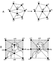
図9Aに示されるように、斜線の部分の画像からなるテクスチャと、顔の部分の画像からなるテクスチャの2つの異なるテクスチャが混在して1つのポリゴンモデルに貼り付けられている。図9Bは、図9Aに示されるモデルでのある連続したエッジ列を示している。この図9Aおよび図9Bに示されるモデルにおいて、例えば頂点v4 と頂点v5 とからなるエッジe(v4 ,v5 )を除去し、除去後に頂点v4 が残される場合、除去対象エッジe(v4 ,v5 )の中間に頂点v4 に基づく頂点v4 ’を配置する処理を行うと、図9Cに示されるように、エッジの輪郭線部が変化する。 As shown in FIG. 9A, two different textures, that is, a texture composed of a hatched portion image and a texture composed of a face portion image are mixed and pasted on one polygon model. FIG. 9B shows a continuous edge sequence in the model shown in FIG. 9A. In the model shown in FIGS. 9A and 9B, for example, when the edge e (v 4 , v 5 ) composed of the vertex v 4 and the vertex v 5 is removed and the vertex v 4 remains after the removal, the removal target edge e (v 4, v 5) intermediate the performed processing for arranging the vertex v 4 'based on the vertex v 4, and as shown in FIG. 9C, the contour portion of the edge is varied.
この場合、頂点v3 〜頂点v6 までのそれぞれの頂点に対して顔の画像の輪郭部も貼り付けられているから、図9Dに示されるように、貼り付けていた2つの画像の形状が崩れてしまう。この例では、顔の絵の下部分形状が大きく変化し、斜線の画像が増えてしまうことになる。このように、画像の輪郭部が割り当てられているモデルのエッジでは、上述のように単純にエッジ除去を繰り返すと、近似化後の品質を悪化させることになる。 In this case, since the contour portion of the face image is also pasted to each of the vertices from vertex v 3 to vertex v 6 , the shapes of the two pasted images are as shown in FIG. 9D. It will collapse. In this example, the shape of the lower part of the face picture changes greatly and the number of hatched images increases. As described above, if the edge removal of the model to which the contour portion of the image is assigned is simply repeated as described above, the quality after the approximation is deteriorated.
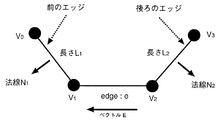
これを防ぐためには、テクスチャの境界部分になるエッジの除去評価関数を導入し、エッジ除去によってテクスチャ境界の形が大きく変わる場合には、次の何れかの手法を用いる必要がある。すなわち、第1の手法としては、そのエッジを除去しない。第2の手法としては、エッジは除去するが、除去後の頂点位置の移動量を調節する。このときの各エッジの除去評価関数には、次に示す数式(2)が用いられる。また、図10は、この数式(2)を説明するための図を示す。 In order to prevent this, it is necessary to introduce one of the following methods when an edge removal evaluation function that becomes a boundary portion of the texture is introduced and the shape of the texture boundary is greatly changed by edge removal. That is, as a first method, the edge is not removed. As a second method, the edge is removed, but the amount of movement of the vertex position after the removal is adjusted. The following formula (2) is used for the removal evaluation function of each edge at this time. FIG. 10 is a diagram for explaining the mathematical formula (2).
![]()
![]()
ここで、Eはエッジeの向きと長さを持つベクトル、Niはエッジの法線ベクトル、Liはエッジの長さをそれぞれ示す。iの範囲は、除去対象となるエッジの前後に存在する境界線のエッジ全体である。この数式(2)の意味するところは、境界部分のエッジを取り除いた場合の面積変化分である。したがって、数式(2)の計算値が大きな場合には、エッジ除去による輪郭線部分の変化が大きくなる。 Here, E represents a vector having the direction and length of the edge e, Ni represents a normal vector of the edge, and Li represents the length of the edge. The range of i is the entire boundary edge existing before and after the edge to be removed. The expression (2) means an area change when the edge of the boundary portion is removed. Therefore, when the calculated value of Equation (2) is large, the change in the contour portion due to edge removal becomes large.
すなわち、数式(2)の計算値が大きな場合には、テクスチャの輪郭線部での画像変化が大きくなり、結果としてテクスチャ形状の崩れが発生する恐れがあることを示す。これを防ぐためには、上述の第1の手法のように、そのエッジを除去しないという手法もあるが、上述の第2の手法のように、数式(2)の値が指定された値より小さくなる範囲内でエッジ除去後のテクスチャ座標を移動させ、結果として輪郭線部の変化量を小さくさせる手法もある。第2の手法を用いることにより、近似化後のテクスチャの崩れを抑えることができる。 That is, when the calculated value of Equation (2) is large, the image change at the contour line portion of the texture becomes large, and as a result, the texture shape may be collapsed. In order to prevent this, there is a method in which the edge is not removed as in the first method described above, but the value of Expression (2) is smaller than a specified value as in the second method described above. There is also a method of moving the texture coordinates after the edge removal within a certain range, and as a result, reducing the amount of change in the contour portion. By using the second method, the collapse of the texture after the approximation can be suppressed.
以上のようにして、所望の精度を持ったテクスチャを貼り付けた近似化ポリゴンモデルを得ることができる。この場合、オリジナルのモデルに対してテクスチャが貼り付けられていれば、近似化後に、モデルに対して再度テクスチャを貼り付ける必要は無く、自動的にテクスチャ付きの近似化モデルを得ることができる。 As described above, an approximate polygon model to which a texture having a desired accuracy is attached can be obtained. In this case, if the texture is pasted on the original model, it is not necessary to paste the texture on the model again after the approximation, and an approximate model with a texture can be automatically obtained.
上述したように、ステップS2からステップS6までの処理を繰り返して得られた近似化モデルは、それぞれハードディスク6やメモリ7といった外部記憶装置に記憶されるが、ステップS8での表示の際には、この外部記憶装置に記憶された近似化モデルが読み出され描画され表示装置8に表示される。この表示は、上述の従来技術でも説明したように、例えばモデルが遠くに配置されたことにより画面上で小さくなったり、あるいは画面の注目点から外れたことにより観察者がそのモデルに注目しなくなった場合には、より近似化された階層のモデルに切り換えられて行われる。
As described above, the approximation models obtained by repeating the processing from step S2 to step S6 are stored in external storage devices such as the
この近似化モデルの切り替えの際に、近似化の程度が大きく異なるモデルに急に切り替えると、この切り替えの瞬間に、表示されているモデルの形状に急激な変化が生じ、観察者に対して違和感を与えてしまう。 When switching between approximation models, if the model is suddenly switched to a model with a different degree of approximation, the shape of the displayed model will change abruptly at the moment of switching, and the observer will feel uncomfortable. Will be given.
この違和感を与えないためには、近似度を少しずつ変えた多数のモデルを用意し外部記憶装置に記憶させ、これらのモデルを順に切り換えながら表示を行うようにすればよい。しかし、この場合には、記憶するモデルの量が増えてしまい、効率的ではない。そこで、少ないモデル数でもスムーズで連続な変換を実現するため、離散的な階層間でモデルを補間し、中間階層のモデルを得るようにすればよい。 In order not to give this uncomfortable feeling, a large number of models whose degree of approximation is changed little by little are prepared and stored in an external storage device, and these models are displayed while being switched in order. However, in this case, the amount of models to be stored increases, which is not efficient. Therefore, in order to realize smooth and continuous conversion with a small number of models, it is only necessary to interpolate models between discrete layers to obtain a model of an intermediate layer.
例えば、上述の図4に示した例においては、エッジe(v1 ,v2 )を除去した後の頂点がv’とされているが、この頂点v’は、エッジe(v1 ,v2 )における頂点v1 およびv2 が互いに近づいて頂点v’となったと考えることができる。すなわち、頂点v1 およびv2 は、結果として頂点v’に統合されている。このように、エッジ除去前後での頂点の対応関係は分かっているから、その頂点の対応関係を利用してエッジ除去前後のデータから、エッジ除去前後の間でのデータを補間により得ることが可能である。 For example, in the example shown in FIG. 4 described above, the vertex after removing the edge e (v 1 , v 2 ) is v ′, but this vertex v ′ is the edge e (v 1 , v It can be considered that the vertices v 1 and v 2 in 2 ) approach each other and become the vertex v ′. That is, vertices v 1 and v 2 are consequently integrated into vertex v ′. Thus, since the correspondence between vertices before and after edge removal is known, it is possible to interpolate data before and after edge removal from the data before and after edge removal using the correspondence between the vertices. It is.
このような、離散的な階層間における中間階層の近似化モデルの形成方法は、先に本発明者の提案にかかる特願平6−248602号において詳細に説明されている。 Such a method of forming an approximation model of an intermediate hierarchy between discrete hierarchies has been described in detail in Japanese Patent Application No. 6-248602 according to the proposal of the present inventor.
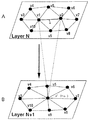
図11は、このように、2つの階層間における頂点の対応関係を利用した、中間階層の近似化モデルの形成を示す。図11において、エッジ除去前を図11Aに示すように階層N、エッジ除去後を図11Cに示すように階層N+1として、この2つの階層から図6Bに示す中間階層N’のモデルを得ている。 FIG. 11 shows the formation of an intermediate layer approximation model using the vertex correspondence between two layers in this way. In FIG. 11, the model of the intermediate layer N ′ shown in FIG. 6B is obtained from these two layers, with the layer N before edge removal shown in FIG. 11A and the layer N + 1 after edge removal shown in FIG. 11C. .
この例では、階層Nのエッジe(v1 ,v2 )を構成する頂点v1 およびv2 とが階層N+1ではv1 になり、消えた頂点v2 は、v1 に統合されている。この頂点対応関係から、中間階層N’において階層Nのエッジe(v1 ,v2 )に対応するエッジe’(v1 ’,v2 ’)を構成する頂点v1 ’,v2 ’の位置は、階層Nと階層N+1との間における線形補間で得ることができる。ここでは1つの中間階層を得る例を示しているが、所望の中間階層数に応じて、線形補間の度合いを変え、複数の中間階層を得ることができる。この中間階層の近似化モデルの作成は、モデルが表示される状況に応じてリアルタイムに行うことができる。 In this example, the vertices v 1 and v 2 constituting the edge e (v 1 , v 2 ) of the hierarchy N become v 1 in the hierarchy N + 1, and the disappeared vertex v 2 is integrated into v 1 . From this vertex correspondence, the vertices v 1 ′, v 2 ′ constituting the edge e ′ (v 1 ′, v 2 ′) corresponding to the edge e (v 1 , v 2 ) of the hierarchy N in the intermediate hierarchy N ′ The position can be obtained by linear interpolation between level N and level N + 1. Here, an example in which one intermediate layer is obtained is shown, but a plurality of intermediate layers can be obtained by changing the degree of linear interpolation according to the desired number of intermediate layers. This intermediate layer approximation model can be created in real time according to the situation in which the model is displayed.
なお、ここでは、この中間階層の近似化モデルは、モデルの表示を行いながらリアルタイムに作成され表示されるように説明したが、これはこの例に限定されるものではない。例えば、中間階層の近似化モデルを予め作成し外部記憶装置に記憶しておき、表示の際にこの記憶された中間階層の近似化モデルを読み出すようにしてもよい。 Here, the intermediate layer approximation model has been described as being created and displayed in real time while displaying the model, but this is not limited to this example. For example, an intermediate layer approximation model may be created in advance and stored in an external storage device, and the stored intermediate layer approximation model may be read out at the time of display.
ここでは、1つのエッジを除去した場合を例としてあげたが、実際のモデルの近似化においてはエッジの除去を複数回繰り返すため、ある階層の1頂点は、よりオリジナルモデルに近い別な階層の複数の頂点に対応する。このような2つの階層間における頂点の対応関係を利用すれば、全ての階層間でモデルの頂点を対応付けすることが可能となる。こうして得た頂点の対応関係に基づいて、中間階層のモデルを得る。 Here, the case where one edge is removed is taken as an example. However, in the approximation of an actual model, the edge removal is repeated a plurality of times, so that one vertex of a hierarchy is in a different hierarchy closer to the original model. Corresponds to multiple vertices. By using such vertex correspondence between two hierarchies, it is possible to associate model vertices between all hierarchies. Based on the vertex correspondence obtained in this way, an intermediate layer model is obtained.
また、上述したように、テクスチャでの画像データ座標は、それぞれモデルの各頂点に割り当てられているから、このモデル頂点の場合と同様にして頂点v1 と頂点v2 とにそれぞれ割り当てられたテクスチャ座標vt1 およびvt2 の補間により、中間階層でのテクスチャを貼り付けたモデルを得ることが可能である。この処理により、スムーズにオリジナルから最も近似化したモデルまでを連続して得ることができる。 Further, as described above, since the image data coordinates in the texture are assigned to the respective vertices of the model, the textures assigned to the vertices v 1 and v 2 in the same manner as in the case of the model vertices. By interpolating the coordinates vt 1 and vt 2 , it is possible to obtain a model to which a texture at an intermediate layer is pasted. By this processing, it is possible to obtain continuously from the original to the most approximate model smoothly.
以上の処理により、離散的な階層的近似化モデルが得られると共に、その中間階層のモデルも得ることが可能となる。このようにして得られ、記憶された近似化モデルは、ステップS8において、表示装置8における画面での見かけのモデルの大きさ、位置、速度、視聴者の注目点に応じて切り替えられ表示される。図7は、この実施の一形態により得られた近似化モデルの例を示す。
Through the above processing, a discrete hierarchical approximation model can be obtained, and a model of the intermediate hierarchy can also be obtained. The approximation model obtained and stored in this manner is switched and displayed in step S8 according to the size, position, speed, and attention point of the viewer on the screen of the
図12は、この実施の一形態による処理結果の一例を模式的に示す。この例では、オリジナルモデルは182個の頂点,360個の面,279個のテクスチャ座標からなる球体である。この球体に、テクスチャとして地球の画像が貼り付けられている。そして、オリジナルモデルに対して頂点数比較で60%ずつ減少させて近似化している。図13は、同じ近似化モデルのテクスチャを張らない場合のモデルのワイヤーフレーム状態を示す。図12では、画像が一貫して保たれているために、どれほど近似化されているかがわかりにくいが、図13に示されるような、テクスチャ画像を貼り付ける前の近似化状態では、近似化の進行がはっきりと見て取れる。 FIG. 12 schematically shows an example of the processing result according to this embodiment. In this example, the original model is a sphere composed of 182 vertices, 360 faces, and 279 texture coordinates. An image of the earth is pasted on this sphere as a texture. Then, the original model is approximated by decreasing by 60% by comparing the number of vertices. FIG. 13 shows the wire frame state of the model when the texture of the same approximate model is not stretched. In FIG. 12, since the images are kept consistently, it is difficult to understand how much the approximation is performed. However, in the approximation state before pasting the texture image as shown in FIG. Progress can be clearly seen.
また、図13により具体的に示されるように、この発明を用いることにより、頂点数を、オリジナルモデルの36%や21.6%にまで落とした場合でも、オリジナルモデルが持つ大局的な形状を損なうこと無く階層的近似化モデルを得ることができる。 Further, as specifically shown in FIG. 13, by using this invention, even when the number of vertices is reduced to 36% or 21.6% of the original model, the general shape of the original model is obtained. A hierarchical approximation model can be obtained without loss.
なお、上述では、ポリゴンモデルにテクスチャ画像を貼り付けた場合について説明したが、この発明は、勿論、テクスチャ画像を貼り付けない場合についても適用することが可能である。この場合には、上述の図1に示されるフローチャートにおいて、ステップS6を省略することができる。 In the above description, the texture image is pasted on the polygon model. However, the present invention can be applied to a case where the texture image is not pasted. In this case, step S6 can be omitted in the flowchart shown in FIG.
S2 エッジ評価のステップ
S3 エッジソートのステップ
S4 エッジ除去のステップ
S5 頂点位置決定のステップ
S6 テクスチャ除去およびテクスチャ座標位置決定のステップ
S2 Edge evaluation step S3 Edge sorting step S4 Edge removal step S5 Vertex position determination step S6 Texture removal and texture coordinate position determination step
Claims (18)
所望の階層のグラフィックモデルの統合された1つの頂点と、上記統合された1つの頂点に対応する別の階層の統合前の2つの頂点の情報とから、補間する階層の新たな2つの頂点の位置と生成された頂点間のエッジを決定するステップを
コンピュータに実行させるグラフィックモデル生成方法。 From the approximate graphic model obtained by performing the approximation that sequentially integrates the vertices with respect to the original graphic model having a plurality of vertices and edges formed between the vertices and the surface defined by the plurality of edges, A graphic model generation method for generating a graphic model close to the original,
From the integrated one vertex of the graphic model of the desired hierarchy and the information of the two vertices before the integration of another hierarchy corresponding to the integrated one vertex , new two vertices of the hierarchy to be interpolated are obtained. A graphic model generation method for causing a computer to execute a step of determining an edge between a position and a generated vertex.
請求項1記載のグラフィックモデル生成方法。 The graphic model generation method according to claim 1, wherein one edge is generated between the two generated vertices.
請求項1記載のグラフィックモデル生成方法。 The graphic model generation method according to claim 1, further comprising assigning a texture to a surface formed by the generated two vertices.
請求項1記載のグラフィックモデル生成方法。 The graphic model generation method according to claim 1, wherein the surface defined by the plurality of edges is a triangle.
請求項1記載のグラフィックモデル生成方法。 The graphic model generation method according to claim 1, wherein the stored vertex information is read and used.
請求項1記載のグラフィックモデル生成方法。 The graphic model generation method according to claim 1, wherein the stored information of the approximate graphic model is read and used.
請求項1記載のグラフィックモデル生成方法。 The graphic model generation method according to claim 1, further comprising storing the generated graphic model closer to the original.
請求項1記載のグラフィックモデル生成方法。 The graphic model generation method according to claim 1, wherein the process of generating two vertices from one vertex of the graphic model based on the vertex information integrated at the time of approximation is repeated a plurality of times.
請求項1記載のグラフィックモデル生成方法。 2. The graphic model generation method according to claim 1, wherein in the approximation in which vertices are sequentially integrated from the original graphic model, the approximation is repeated according to the accuracy of the approximation.
所望の階層のグラフィックモデルの統合された1つの頂点と、上記統合された1つの頂点に対応する別の階層の統合前の2つの頂点の情報とから、補間する階層の新たな2つの頂点の位置と生成された頂点間のエッジを決定する
グラフィックモデル生成装置。 From the approximate graphic model obtained by performing the approximation that sequentially integrates the vertices with respect to the original graphic model having a plurality of vertices and edges formed between the vertices and the surface defined by the plurality of edges, A graphic model generation device that generates a graphic model close to the original,
From the integrated one vertex of the graphic model of the desired hierarchy and the information of the two vertices before the integration of another hierarchy corresponding to the integrated one vertex , new two vertices of the hierarchy to be interpolated are obtained. A graphic model generation device that determines an edge between a position and a generated vertex.
請求項10記載のグラフィックモデル生成装置。 The graphic model generation apparatus according to claim 10, wherein one edge is generated between the two generated vertices.
請求項10記載のグラフィックモデル生成装置。 The graphic model generation apparatus according to claim 10, further comprising assigning a texture to a surface formed by the generated two vertices.
請求項10記載のグラフィックモデル生成装置。 The graphic model generation apparatus according to claim 10, wherein the surface defined by the plurality of edges is a triangle.
請求項10記載のグラフィックモデル生成装置。 The graphic model generation apparatus according to claim 10, wherein the vertex information is read from an external storage device and used.
請求項10記載のグラフィックモデル生成装置。 The graphic model generation apparatus according to claim 10, wherein information on the approximate graphic model is read from an external storage device and used.
請求項10記載のグラフィックモデル生成装置。 The graphic model generation apparatus according to claim 10, further comprising storing the generated graphic model closer to the original in an external storage device.
請求項10記載のグラフィックモデル生成装置。 The graphic model generation apparatus according to claim 10, wherein the process of generating two vertices from one vertex of the graphic model based on the vertex information integrated at the time of approximation is repeated a plurality of times.
請求項10記載のグラフィックモデル生成装置。 The graphic model generation apparatus according to claim 10, wherein the approximation is repeated according to the accuracy of approximation in the approximation in which vertices are sequentially integrated from the original graphic model.
Priority Applications (1)
| Application Number | Priority Date | Filing Date | Title |
|---|---|---|---|
| JP2005299609A JP4355697B2 (en) | 1995-12-18 | 2005-10-14 | Graphic model generation method and graphic model generation apparatus |
Applications Claiming Priority (2)
| Application Number | Priority Date | Filing Date | Title |
|---|---|---|---|
| JP34840395 | 1995-12-18 | ||
| JP2005299609A JP4355697B2 (en) | 1995-12-18 | 2005-10-14 | Graphic model generation method and graphic model generation apparatus |
Related Parent Applications (1)
| Application Number | Title | Priority Date | Filing Date |
|---|---|---|---|
| JP27306496A Division JP3785700B2 (en) | 1995-12-18 | 1996-09-24 | Approximation method and apparatus |
Publications (2)
| Publication Number | Publication Date |
|---|---|
| JP2006040309A JP2006040309A (en) | 2006-02-09 |
| JP4355697B2 true JP4355697B2 (en) | 2009-11-04 |
Family
ID=18396793
Family Applications (2)
| Application Number | Title | Priority Date | Filing Date |
|---|---|---|---|
| JP27306496A Expired - Fee Related JP3785700B2 (en) | 1995-12-18 | 1996-09-24 | Approximation method and apparatus |
| JP2005299609A Expired - Lifetime JP4355697B2 (en) | 1995-12-18 | 2005-10-14 | Graphic model generation method and graphic model generation apparatus |
Family Applications Before (1)
| Application Number | Title | Priority Date | Filing Date |
|---|---|---|---|
| JP27306496A Expired - Fee Related JP3785700B2 (en) | 1995-12-18 | 1996-09-24 | Approximation method and apparatus |
Country Status (2)
| Country | Link |
|---|---|
| US (3) | US5963668A (en) |
| JP (2) | JP3785700B2 (en) |
Families Citing this family (21)
| Publication number | Priority date | Publication date | Assignee | Title |
|---|---|---|---|---|
| US7859551B2 (en) | 1993-10-15 | 2010-12-28 | Bulman Richard L | Object customization and presentation system |
| JP3785700B2 (en) * | 1995-12-18 | 2006-06-14 | ソニー株式会社 | Approximation method and apparatus |
| JPH10134208A (en) | 1996-10-31 | 1998-05-22 | Sony Corp | Shape data approximating method and plotting device |
| JP3645702B2 (en) * | 1997-12-25 | 2005-05-11 | オリンパス株式会社 | Electronic camera |
| JP3515689B2 (en) * | 1998-05-22 | 2004-04-05 | 富士通株式会社 | 3D polygon display device using hierarchical polygon data |
| US6421051B1 (en) | 1998-06-18 | 2002-07-16 | Spatial Corporation | Multi-resolution geometry |
| JP2000200361A (en) * | 1998-08-07 | 2000-07-18 | Sega Enterp Ltd | Image processor and information recording medium |
| KR100346787B1 (en) * | 1999-06-17 | 2002-08-01 | 한국전자통신연구원 | Multiresolution polygon graphic model generation and saving method |
| JP4759109B2 (en) * | 1999-06-18 | 2011-08-31 | シュガーローフ アクイジションズ,エルエルシー | Multi-resolution geometrical arrangement |
| DE19928231C2 (en) * | 1999-06-21 | 2003-03-27 | Max Planck Gesellschaft | Method and device for segmenting a point distribution |
| DE19957366C1 (en) * | 1999-11-29 | 2001-04-05 | Daimler Chrysler Ag | Measuring position determination method for object measurement has triangular grid defined by reference points on object surface with measuring point assigned to each triangle |
| US7415156B2 (en) * | 2000-01-28 | 2008-08-19 | Carnegie Mellon University | Parametric shape grammar interpreter |
| US7050051B1 (en) * | 2000-01-28 | 2006-05-23 | Carnegie Mellon University | Parametric shape grammar interpreter |
| JP3746211B2 (en) | 2001-08-03 | 2006-02-15 | 株式会社ソニー・コンピュータエンタテインメント | Drawing apparatus, drawing method, drawing program, computer-readable recording medium recording the drawing program, and graphics processor |
| JP4501479B2 (en) * | 2004-03-18 | 2010-07-14 | カシオ計算機株式会社 | Polygon model simplification method, image processing apparatus, image drawing apparatus, and program |
| EP1688885B1 (en) * | 2005-02-03 | 2013-06-19 | Samsung Electronics Co., Ltd. | Method, apparatus, and medium for transforming graphic data of an object |
| US7876322B2 (en) * | 2005-11-29 | 2011-01-25 | Siemens Corporation | Method and apparatus for fast and efficient mesh simplification |
| JP4636146B2 (en) * | 2008-09-05 | 2011-02-23 | ソニー株式会社 | Image processing method, image processing apparatus, program, and image processing system |
| JP4887419B2 (en) * | 2009-12-24 | 2012-02-29 | シュガーローフ アクイジションズ,エルエルシー | Multi-resolution geometrical arrangement |
| GB201402879D0 (en) * | 2014-02-18 | 2014-04-02 | Zero360 Inc | Display Control |
| CN110998666B (en) * | 2017-08-08 | 2023-10-20 | 索尼公司 | Information processing device, information processing method, and program |
Family Cites Families (41)
| Publication number | Priority date | Publication date | Assignee | Title |
|---|---|---|---|---|
| US4152766A (en) | 1978-02-08 | 1979-05-01 | The Singer Company | Variable resolution for real-time simulation of a polygon face object system |
| US4600919A (en) | 1982-08-03 | 1986-07-15 | New York Institute Of Technology | Three dimensional animation |
| US4783829A (en) | 1983-02-23 | 1988-11-08 | Hitachi, Ltd. | Pattern recognition apparatus |
| JPS60200376A (en) * | 1984-03-26 | 1985-10-09 | Hitachi Ltd | Partial pattern matching system |
| US4694407A (en) | 1985-06-11 | 1987-09-15 | Rca Corporation | Fractal generation, as for video graphic displays |
| JPS63118890A (en) * | 1986-11-06 | 1988-05-23 | Fujitsu Ltd | System for processing polygonal image with painting surface |
| US4941193A (en) * | 1987-10-02 | 1990-07-10 | Iterated Systems, Inc. | Methods and apparatus for image compression by iterated function system |
| JP2667835B2 (en) | 1987-10-09 | 1997-10-27 | 株式会社日立製作所 | Computer Graphics Display |
| GB2213345B (en) | 1987-12-28 | 1992-01-15 | Mitsubishi Electric Corp | Image data filing system |
| US5276786A (en) | 1988-09-05 | 1994-01-04 | Quantel Limited | Video graphics systems separately processing an area of the picture before blending the processed area into the original picture |
| US5040130A (en) * | 1988-09-20 | 1991-08-13 | International Business Machines Corporation | Computer graphics boundary--defined area clippping and extraneous edge deletion method |
| EP0405106A3 (en) * | 1989-06-16 | 1992-04-08 | International Business Machines Corporation | Construction of minkowski sums and derivative morphological combinations of arbitrary polyhedra in cad/cam systems |
| US4969204A (en) | 1989-11-29 | 1990-11-06 | Eastman Kodak Company | Hybrid residual-based hierarchical storage and display method for high resolution digital images in a multiuse environment |
| JPH07101461B2 (en) | 1990-05-02 | 1995-11-01 | 株式会社エイ・ティ・アール通信システム研究所 | Eye-tracking high-speed image generation and display method |
| AU8932191A (en) * | 1990-11-30 | 1992-06-25 | Cambridge Animation Systems Limited | Image synthesis and processing |
| US5373375A (en) | 1990-12-21 | 1994-12-13 | Eastman Kodak Company | Metric conversion mechanism for digital images in a hierarchical, multi-resolution, multi-use environment |
| US5341466A (en) | 1991-05-09 | 1994-08-23 | New York University | Fractal computer user centerface with zooming capability |
| JPH05266213A (en) * | 1991-12-27 | 1993-10-15 | Toshiba Corp | High-speed display system for three-dimensional space data |
| US5448686A (en) | 1992-01-02 | 1995-09-05 | International Business Machines Corporation | Multi-resolution graphic representation employing at least one simplified model for interactive visualization applications |
| US5590248A (en) * | 1992-01-02 | 1996-12-31 | General Electric Company | Method for reducing the complexity of a polygonal mesh |
| JPH05250445A (en) * | 1992-03-09 | 1993-09-28 | A T R Tsushin Syst Kenkyusho:Kk | Three-dimensional model data generating device |
| JP2709993B2 (en) | 1992-04-06 | 1998-02-04 | 株式会社エイ・ティ・アール通信システム研究所 | High-speed video generator |
| US5367465A (en) | 1992-06-24 | 1994-11-22 | Intel Corporation | Solids surface grid generation for three-dimensional topography simulation |
| US5490239A (en) | 1992-10-01 | 1996-02-06 | University Corporation For Atmospheric Research | Virtual reality imaging system |
| US5384904A (en) | 1992-12-08 | 1995-01-24 | Intel Corporation | Image scaling using real scale factors |
| JPH06231276A (en) * | 1993-01-29 | 1994-08-19 | Nippon Steel Corp | Polygon generation method for three-dimensional object display |
| JPH06251126A (en) | 1993-02-25 | 1994-09-09 | Hitachi Ltd | Image synthesizing method |
| JP3466661B2 (en) | 1993-06-29 | 2003-11-17 | キヤノン株式会社 | Image processing apparatus and method |
| US5471568A (en) * | 1993-06-30 | 1995-11-28 | Taligent, Inc. | Object-oriented apparatus and method for scan line conversion of graphic edges |
| DE69324363T2 (en) * | 1993-10-11 | 1999-08-26 | Hewlett Packard Gmbh | Process for chamfering the edges of a geometric object in a computer-aided design system |
| AU1433495A (en) * | 1993-12-12 | 1995-06-27 | Asp Solutions Usa, Inc. | Apparatus and method for signal processing |
| JPH08110950A (en) | 1994-09-08 | 1996-04-30 | Sony Corp | Plotting device and method utilizing hierarchical approximation system for graphic data |
| US5506947A (en) * | 1994-09-22 | 1996-04-09 | International Business Machines Corporation | Curve and surface smoothing without shrinkage |
| US5689577A (en) | 1994-10-14 | 1997-11-18 | Picker International, Inc. | Procedure for the simplification of triangular surface meshes for more efficient processing |
| US5613051A (en) | 1994-12-21 | 1997-03-18 | Harris Corp. | Remote image exploitation display system and method |
| DE19508823A1 (en) | 1995-03-11 | 1996-09-12 | Philips Patentverwaltung | Process for replicating the surface of an object |
| KR0181059B1 (en) * | 1995-03-18 | 1999-05-01 | 배순훈 | A contour approximation apparatus for representing a contour of an object |
| US5796400A (en) | 1995-08-07 | 1998-08-18 | Silicon Graphics, Incorporated | Volume-based free form deformation weighting |
| JP3785700B2 (en) * | 1995-12-18 | 2006-06-14 | ソニー株式会社 | Approximation method and apparatus |
| US5963209A (en) | 1996-01-11 | 1999-10-05 | Microsoft Corporation | Encoding and progressive transmission of progressive meshes |
| US5751852A (en) * | 1996-04-29 | 1998-05-12 | Xerox Corporation | Image structure map data structure for spatially indexing an imgage |
-
1996
- 1996-09-24 JP JP27306496A patent/JP3785700B2/en not_active Expired - Fee Related
- 1996-11-25 US US08/755,129 patent/US5963668A/en not_active Expired - Lifetime
-
1999
- 1999-08-04 US US09/366,549 patent/US6396952B1/en not_active Ceased
-
2004
- 2004-02-19 US US10/781,265 patent/USRE42366E1/en not_active Expired - Lifetime
-
2005
- 2005-10-14 JP JP2005299609A patent/JP4355697B2/en not_active Expired - Lifetime
Also Published As
| Publication number | Publication date |
|---|---|
| JP2006040309A (en) | 2006-02-09 |
| US5963668A (en) | 1999-10-05 |
| JP3785700B2 (en) | 2006-06-14 |
| US6396952B1 (en) | 2002-05-28 |
| USRE42366E1 (en) | 2011-05-17 |
| JPH09231401A (en) | 1997-09-05 |
Similar Documents
| Publication | Publication Date | Title |
|---|---|---|
| JP4355697B2 (en) | Graphic model generation method and graphic model generation apparatus | |
| EP1064619B1 (en) | Stochastic level of detail in computer animation | |
| JP5232358B2 (en) | Rendering outline fonts | |
| JP4385524B2 (en) | Polygon data generation method and image display apparatus using the same | |
| US7903112B2 (en) | Drawing processing apparatus, texture processing apparatus, and tessellation method | |
| US5369739A (en) | Apparatus and method for generating point sample masks in a graphics display system | |
| US7138999B2 (en) | Refinement of a triangular mesh representing a three-dimensional object | |
| US7924278B2 (en) | Real-time GPU rendering of piecewise algebraic surfaces | |
| US20040075655A1 (en) | 3D computer graphics processing apparatus and method | |
| JPH04287292A (en) | Method and device for rendering trimmed parametric surface | |
| JPH0776991B2 (en) | NURBS data conversion method and apparatus | |
| US6597368B1 (en) | Morphing image processing system using polygon reduction processing | |
| JP3785709B2 (en) | Shape data approximation method and drawing apparatus | |
| JPH11339061A (en) | Three dimensional polygon display device using hierarchical polygon data | |
| US6326968B1 (en) | Image data approximation considering normal vectors | |
| JP2003504697A (en) | Anti-aliasing of subsampled texture edges | |
| US7015917B2 (en) | Curved surface subdivision apparatus | |
| US6690827B1 (en) | Approximation method of shape data, information processing apparatus and medium | |
| JP4009289B2 (en) | Method for determining a weighting factor for color-calculating a texel color value associated with a footprint | |
| JP3071387B2 (en) | Interpolation device, interpolation method, and image generation device | |
| Chen et al. | Ray casting free‐form deformed‐volume objects | |
| JP2655056B2 (en) | Texture data generator | |
| JP4383585B2 (en) | Computer graphic processing method | |
| Bruijns | Quadratic Bezier triangles as drawing primitives | |
| KR100277546B1 (en) | Computation Method Using Lookup Tables in Geometry for Surface Model Rendering |
Legal Events
| Date | Code | Title | Description |
|---|---|---|---|
| A521 | Written amendment |
Free format text: JAPANESE INTERMEDIATE CODE: A523 Effective date: 20051111 |
|
| A621 | Written request for application examination |
Free format text: JAPANESE INTERMEDIATE CODE: A621 Effective date: 20051111 |
|
| RD04 | Notification of resignation of power of attorney |
Free format text: JAPANESE INTERMEDIATE CODE: A7424 Effective date: 20060210 |
|
| A131 | Notification of reasons for refusal |
Free format text: JAPANESE INTERMEDIATE CODE: A131 Effective date: 20070109 |
|
| A521 | Written amendment |
Free format text: JAPANESE INTERMEDIATE CODE: A523 Effective date: 20070309 |
|
| A131 | Notification of reasons for refusal |
Free format text: JAPANESE INTERMEDIATE CODE: A131 Effective date: 20070417 |
|
| A521 | Written amendment |
Free format text: JAPANESE INTERMEDIATE CODE: A523 Effective date: 20070615 |
|
| A131 | Notification of reasons for refusal |
Free format text: JAPANESE INTERMEDIATE CODE: A131 Effective date: 20070717 |
|
| A02 | Decision of refusal |
Free format text: JAPANESE INTERMEDIATE CODE: A02 Effective date: 20080212 |
|
| A521 | Written amendment |
Free format text: JAPANESE INTERMEDIATE CODE: A523 Effective date: 20080414 |
|
| A911 | Transfer to examiner for re-examination before appeal (zenchi) |
Free format text: JAPANESE INTERMEDIATE CODE: A911 Effective date: 20080424 |
|
| A912 | Re-examination (zenchi) completed and case transferred to appeal board |
Free format text: JAPANESE INTERMEDIATE CODE: A912 Effective date: 20080620 |
|
| A521 | Written amendment |
Free format text: JAPANESE INTERMEDIATE CODE: A523 Effective date: 20090619 |
|
| A01 | Written decision to grant a patent or to grant a registration (utility model) |
Free format text: JAPANESE INTERMEDIATE CODE: A01 |
|
| A61 | First payment of annual fees (during grant procedure) |
Free format text: JAPANESE INTERMEDIATE CODE: A61 Effective date: 20090803 |
|
| FPAY | Renewal fee payment (event date is renewal date of database) |
Free format text: PAYMENT UNTIL: 20120807 Year of fee payment: 3 |
|
| FPAY | Renewal fee payment (event date is renewal date of database) |
Free format text: PAYMENT UNTIL: 20130807 Year of fee payment: 4 |
|
| R250 | Receipt of annual fees |
Free format text: JAPANESE INTERMEDIATE CODE: R250 |
|
| R250 | Receipt of annual fees |
Free format text: JAPANESE INTERMEDIATE CODE: R250 |
|
| R250 | Receipt of annual fees |
Free format text: JAPANESE INTERMEDIATE CODE: R250 |
|
| R250 | Receipt of annual fees |
Free format text: JAPANESE INTERMEDIATE CODE: R250 |
|
| EXPY | Cancellation because of completion of term |