JP4352312B2 - Information processing apparatus and method, program, and recording medium - Google Patents
Information processing apparatus and method, program, and recording medium Download PDFInfo
- Publication number
- JP4352312B2 JP4352312B2 JP2003290053A JP2003290053A JP4352312B2 JP 4352312 B2 JP4352312 B2 JP 4352312B2 JP 2003290053 A JP2003290053 A JP 2003290053A JP 2003290053 A JP2003290053 A JP 2003290053A JP 4352312 B2 JP4352312 B2 JP 4352312B2
- Authority
- JP
- Japan
- Prior art keywords
- user
- service
- information
- service system
- pmd
- Prior art date
- Legal status (The legal status is an assumption and is not a legal conclusion. Google has not performed a legal analysis and makes no representation as to the accuracy of the status listed.)
- Expired - Fee Related
Links
Images


Classifications
-
- G—PHYSICS
- G06—COMPUTING; CALCULATING OR COUNTING
- G06F—ELECTRIC DIGITAL DATA PROCESSING
- G06F15/00—Digital computers in general; Data processing equipment in general
-
- G—PHYSICS
- G06—COMPUTING; CALCULATING OR COUNTING
- G06F—ELECTRIC DIGITAL DATA PROCESSING
- G06F21/00—Security arrangements for protecting computers, components thereof, programs or data against unauthorised activity
- G06F21/70—Protecting specific internal or peripheral components, in which the protection of a component leads to protection of the entire computer
- G06F21/78—Protecting specific internal or peripheral components, in which the protection of a component leads to protection of the entire computer to assure secure storage of data
- G06F21/79—Protecting specific internal or peripheral components, in which the protection of a component leads to protection of the entire computer to assure secure storage of data in semiconductor storage media, e.g. directly-addressable memories
-
- G—PHYSICS
- G06—COMPUTING; CALCULATING OR COUNTING
- G06F—ELECTRIC DIGITAL DATA PROCESSING
- G06F16/00—Information retrieval; Database structures therefor; File system structures therefor
- G06F16/60—Information retrieval; Database structures therefor; File system structures therefor of audio data
-
- G—PHYSICS
- G06—COMPUTING; CALCULATING OR COUNTING
- G06F—ELECTRIC DIGITAL DATA PROCESSING
- G06F21/00—Security arrangements for protecting computers, components thereof, programs or data against unauthorised activity
- G06F21/30—Authentication, i.e. establishing the identity or authorisation of security principals
- G06F21/31—User authentication
- G06F21/32—User authentication using biometric data, e.g. fingerprints, iris scans or voiceprints
-
- G—PHYSICS
- G06—COMPUTING; CALCULATING OR COUNTING
- G06F—ELECTRIC DIGITAL DATA PROCESSING
- G06F21/00—Security arrangements for protecting computers, components thereof, programs or data against unauthorised activity
- G06F21/30—Authentication, i.e. establishing the identity or authorisation of security principals
- G06F21/31—User authentication
- G06F21/34—User authentication involving the use of external additional devices, e.g. dongles or smart cards
- G06F21/35—User authentication involving the use of external additional devices, e.g. dongles or smart cards communicating wirelessly
-
- G—PHYSICS
- G07—CHECKING-DEVICES
- G07C—TIME OR ATTENDANCE REGISTERS; REGISTERING OR INDICATING THE WORKING OF MACHINES; GENERATING RANDOM NUMBERS; VOTING OR LOTTERY APPARATUS; ARRANGEMENTS, SYSTEMS OR APPARATUS FOR CHECKING NOT PROVIDED FOR ELSEWHERE
- G07C9/00—Individual registration on entry or exit
- G07C9/30—Individual registration on entry or exit not involving the use of a pass
- G07C9/32—Individual registration on entry or exit not involving the use of a pass in combination with an identity check
- G07C9/37—Individual registration on entry or exit not involving the use of a pass in combination with an identity check using biometric data, e.g. fingerprints, iris scans or voice recognition
-
- H—ELECTRICITY
- H04—ELECTRIC COMMUNICATION TECHNIQUE
- H04L—TRANSMISSION OF DIGITAL INFORMATION, e.g. TELEGRAPHIC COMMUNICATION
- H04L63/00—Network architectures or network communication protocols for network security
- H04L63/04—Network architectures or network communication protocols for network security for providing a confidential data exchange among entities communicating through data packet networks
- H04L63/0428—Network architectures or network communication protocols for network security for providing a confidential data exchange among entities communicating through data packet networks wherein the data content is protected, e.g. by encrypting or encapsulating the payload
-
- H—ELECTRICITY
- H04—ELECTRIC COMMUNICATION TECHNIQUE
- H04L—TRANSMISSION OF DIGITAL INFORMATION, e.g. TELEGRAPHIC COMMUNICATION
- H04L63/00—Network architectures or network communication protocols for network security
- H04L63/08—Network architectures or network communication protocols for network security for authentication of entities
-
- H—ELECTRICITY
- H04—ELECTRIC COMMUNICATION TECHNIQUE
- H04L—TRANSMISSION OF DIGITAL INFORMATION, e.g. TELEGRAPHIC COMMUNICATION
- H04L63/00—Network architectures or network communication protocols for network security
- H04L63/10—Network architectures or network communication protocols for network security for controlling access to devices or network resources
- H04L63/102—Entity profiles
-
- H—ELECTRICITY
- H04—ELECTRIC COMMUNICATION TECHNIQUE
- H04L—TRANSMISSION OF DIGITAL INFORMATION, e.g. TELEGRAPHIC COMMUNICATION
- H04L9/00—Cryptographic mechanisms or cryptographic arrangements for secret or secure communications; Network security protocols
- H04L9/32—Cryptographic mechanisms or cryptographic arrangements for secret or secure communications; Network security protocols including means for verifying the identity or authority of a user of the system or for message authentication, e.g. authorization, entity authentication, data integrity or data verification, non-repudiation, key authentication or verification of credentials
Description
本発明は、ユーザの利便性を向上させ、さらにユーザにとって快適で安心なサービスを提供できるようにする情報処理装置および方法、プログラム、並びに記録媒体に関する。 The present invention relates to an information processing apparatus and method, a program, and a recording medium that improve user convenience and that can provide a service that is comfortable and secure for the user.
近年、個人情報を提示することで、様々なサービスを受けられるようになった。個人情報としては、名前、住所、嗜好情報、サービスへの認証情報、点数情報、他の人からもらった情報等さまざまな情報があげられる。 In recent years, it has become possible to receive various services by presenting personal information. The personal information includes various information such as name, address, preference information, service authentication information, point information, and information received from other people.
このような個人情報をカードに保存して持ち運び、ユーザが店に入ったとき、ショッピングカートに搭載されたカードリーダによりカードの情報が読み取られ、カードの情報に基づいて、広告を表示したり、場所案内、好みの商品のディスカウント情報などを表示する技術が提案されている(例えば、非特許文献1参照)。 When such personal information is stored in a card and carried, when the user enters the store, the card information is read by a card reader mounted on the shopping cart, and an advertisement is displayed based on the card information, A technique for displaying location information, discount information of a favorite product, and the like has been proposed (see, for example, Non-Patent Document 1).
また、個人情報を利用して、個人認証を行い、商品の購入、支払いなどの処理を便利にしようとする試みも行われている(例えば、特許文献1乃至3参照)。 In addition, attempts have been made to make personal authentication by using personal information and to make processing such as product purchase and payment convenient (for example, see Patent Documents 1 to 3).
特許文献1によれば、ユーザの端末で、商品コードを入力し(または、商品のバーコードを読み込み)、それをページャー等での遠隔通信によりパブリックなネットワークに接続を行い、自宅のPCまたはPCS NCC(Personal Communication Service Network Control Center)に転送し、PCS NCCでは商品コードから商品の値段等の情報をユーザの端末へ転送する。商品情報はユーザの端末にのみ表示され、購入の申し込みを行うと、実際の支払いが電子マネー等で処理される。 According to Patent Document 1, a product code is input (or a product barcode is read) at a user terminal, and the product is connected to a public network by remote communication using a pager or the like. The information is transferred to the NCC (Personal Communication Service Network Control Center), and the PCS NCC transfers information such as the price of the product from the product code to the user's terminal. The merchandise information is displayed only on the user's terminal, and when an application for purchase is made, the actual payment is processed with electronic money or the like.
また、特許文献2は、離れたところから、財務情報を制御するプラットフォームを提供しようとするもので、財務情報の提供は銀行により行われる。また、銀行とノンバンクの間で銀行業務とは関係のないサービスも提供する。
特許文献3は、携帯電話を使って、電子財布、ワイヤレスPIN(personal identification number)パッド、および非接触型のスマートカードの機能を実現しようというものである。携帯電話会社等でのサービスプロバイダーにおいて、アカウントと認証情報を保持し、携帯電話から予め決められた機能コードを入力すると、機能コードがサービスプロバイダーへ転送され要求された処理が行われる。サービスプロバイダーの中央処理装置により、認証が必要か否かの判断を行い、必用であれば個人認証番号を中央処理装置に転送し、中央処理装置にて認証処理を行い取引が行われる。 Japanese Patent Laid-Open No. 2004-228561 is intended to realize functions of an electronic wallet, a wireless PIN (personal identification number) pad, and a contactless smart card using a mobile phone. When a service provider at a mobile phone company or the like holds an account and authentication information and inputs a predetermined function code from the mobile phone, the function code is transferred to the service provider and the requested processing is performed. The central processing unit of the service provider determines whether or not authentication is necessary. If necessary, the personal authentication number is transferred to the central processing unit, and the central processing unit performs authentication processing to perform a transaction.
しかしながら、非特許文献1の技術では、他の店で受けたサービスとの情報交換ができない。また、カードを使っているのがユーザ本人か否かを確認する、なりすまし防止機構がないという課題があった。 However, the technique of Non-Patent Document 1 cannot exchange information with services received at other stores. In addition, there is a problem that there is no anti-spoofing mechanism for checking whether or not the user is using the card.
また、特許文献1の技術では、PCS NCCにおいてデータベースの管理を行うにあたり、商品コードから商品情報を検索するためのデータベース作成等が必要になり、迅速な処理ができないという課題があった。 In addition, the technique of Patent Document 1 has a problem in that when database management is performed in PCS NCC, it is necessary to create a database for searching for product information from a product code, and thus rapid processing cannot be performed.
特許文献2の技術では、サービスの流れを規定しているが、ユーザの端末においてどのような認証処理がなされるかが考慮されていないという課題があった。
In the technique of
特許文献3の技術では、固定的な機能コードが必要となるため、認証システムおよび商品情報に依存した携帯電話等を作成しなければならず、柔軟なシステムの運用が行えず、その結果、ユーザの利便性が損なわれる恐れがあるという課題があった。
Since the technique of
本発明はこのような状況に鑑みてなされたものであり、ユーザの利便性を向上させ、さらにユーザにとって快適で安心なサービスを提供できるようにするものである。 The present invention has been made in view of such circumstances, and is intended to improve user convenience and to provide a service that is comfortable and secure for the user.
本発明の情報処理装置は、ユーザに関連するユーザ情報を格納したメモリと、プログラムモジュールを実行して各部を制御するCPUと、入力手段と、出力手段とを備えた、前記ユーザが所持する携帯型の情報処理装置であって、CPUが通信モジュールを実行することにより、任意のサービスシステムから、該サービスシステムが提供するサービスを特定するサービスIDと、当該サービスを提供する際に読み出し又は変更する必要があるユーザ情報を特定する情報とを含む登録要求を受信すると、CPUが許可項目確認モジュールを実行することにより、前記ユーザ情報を出力手段より提示し、入力手段を介して該ユーザ情報が前記サービスシステムによって読み出し又は変更されることを許可又は拒否するかの指定がなされると、CPUがユーザ制御許可入力モジュールを実行することにより、前記指定に基づいて、前記ユーザ情報に対する読み出し又は変更の許可又は拒否を示すアクセス許可情報を生成し、前記サービスIDと、前記アクセス許可情報と、ユーザ情報とを関連付けて前記メモリに記憶することを特徴とする。 An information processing apparatus according to the present invention includes a memory that stores user information related to a user, a CPU that executes a program module to control each unit, an input unit, and an output unit, and is carried by the user. This type of information processing apparatus executes a communication module by a CPU, and reads or changes a service ID that identifies a service provided by the service system and an arbitrary service system when the service is provided Upon receiving the registration request including information specifying the user information needs, by the CPU executing the authorization entry confirmation module, the present from the output means the user information, is the user information via the input means the When permission or reject or specify be read or changed by a service system is made, CP Executes the user control permission input module to generate access permission information indicating permission or denial of reading or changing the user information based on the designation, and the service ID, the access permission information, and the user Information is stored in association with the memory.
CPUが通信モジュールを実行することにより、準静電界通信、電磁波通信、光通信、または電気的通信により送信されてくる前記登録要求の受信を制御するようにすることができる。 When the CPU executes the communication module , reception of the registration request transmitted by quasi-electrostatic field communication, electromagnetic wave communication, optical communication, or electrical communication can be controlled.
前記情報処理装置の外部の機器を、入力または出力のインタフェースとして利用するようにすることができる。 A device external to the information processing apparatus can be used as an input or output interface.
本発明の情報処理方法は、ユーザに関連するユーザ情報を格納したメモリと、プログラムモジュールを実行して各部を制御するCPUと、入力手段と、出力手段とを備えた、前記ユーザが所持する携帯型の情報処理装置の情報処理方法であって、CPUが通信モジュールを実行することにより、任意のサービスシステムから、該サービスシステムが提供するサービスを特定するサービスIDと、当該サービスを提供する際に読み出し又は変更する必要があるユーザ情報を特定する情報とを含む登録要求を受信すると、CPUが許可項目確認モジュールを実行することにより、前記ユーザ情報を出力手段より提示し、入力手段を介して該ユーザ情報が前記サービスシステムによって読み出し又は変更されることを許可又は拒否するかの指定がなされると、CPUがユーザ制御許可入力モジュールを実行することにより、前記指定に基づいて、前記ユーザ情報に対する読み出し又は変更の許可又は拒否を示すアクセス許可情報を生成し、前記サービスIDと、前記アクセス許可情報と、ユーザ情報とを関連付けて前記メモリに記憶することを特徴とする。 An information processing method according to the present invention includes a memory that stores user information related to a user, a CPU that executes a program module to control each unit, an input unit, and an output unit, and is carried by the user. Information processing method of an information processing apparatus of the type, in which a CPU executes a communication module to provide a service ID for identifying a service provided by the service system and an service provided by the service system. When a registration request including information specifying user information that needs to be read or changed is received, the CPU executes the permission item confirmation module so that the user information is presented from the output unit, and the user information is input via the input unit. of specified ne user information is permitted or refused to be read or modified by the service system When the CPU executes the user control permission input module, the CPU generates access permission information indicating permission or denial of reading or changing the user information based on the designation, the service ID, and the access permission Information and user information are associated with each other and stored in the memory.
本発明のプログラムは、ユーザに関連するユーザ情報を格納したメモリと、入力手段と、出力手段とを備えたコンピュータに、任意のサービスシステムから、該サービスシステムが提供するサービスを特定するサービスIDと、当該サービスを提供する際に読み出し又は変更する必要があるユーザ情報を特定する情報とを含む登録要求を受信する手順と、前記登録要求を受信すると、前記ユーザ情報を出力手段より提示し、入力手段を介して該ユーザ情報が前記サービスシステムによって読み出し又は変更されることを許可又は拒否するかの指定を受け付ける手順と、前記指定がなされると、前記指定に基づいて、前記ユーザ情報に対する読み出し又は変更の許可又は拒否を示すアクセス許可情報を生成し、前記サービスIDと、前記アクセス許可情報と、ユーザ情報とを関連付けて前記メモリに記憶させる手順とを実行させることを特徴とする。 A program according to the present invention includes a service ID for specifying a service provided by a service system from any service system in a computer including a memory storing user information related to the user , an input unit, and an output unit. A procedure for receiving a registration request including information for identifying user information that needs to be read or changed when providing the service; and when receiving the registration request, the user information is presented from the output means and input A procedure for accepting designation of whether to permit or deny that the user information is read or changed by the service system via the means, and when the designation is made, based on the designation, Access permission information indicating permission or denial of change is generated, and the service ID and the access And permission information, in association with user information, characterized in that to execute the procedures to be stored in the memory.
本発明の記録媒体は、ユーザに関連するユーザ情報を格納したメモリと、入力手段と、出力手段とを備えたコンピュータに、任意のサービスシステムから、該サービスシステムが提供するサービスを特定するサービスIDと、当該サービスを提供する際に読み出し又は変更する必要があるユーザ情報を特定する情報とを含む登録要求を受信する手順と、前記登録要求を受信すると、前記ユーザ情報を出力手段より提示し、入力手段を介して該ユーザ情報が前記サービスシステムによって読み出し又は変更されることを許可又は拒否するかの指定を受け付ける手順と、前記指定がなされると、前記指定に基づいて、前記ユーザ情報に対する読み出し又は変更の許可又は拒否を示すアクセス許可情報を生成し、前記サービスIDと、前記アクセス許可情報と、ユーザ情報とを関連付けて前記メモリに記憶させる手順とを実行させるためのプログラムが記録されていることを特徴とする。 The recording medium according to the present invention includes a service ID for identifying a service provided by a service system from any service system in a computer including a memory storing user information related to the user , an input unit, and an output unit. And a procedure for receiving a registration request including information specifying user information that needs to be read or changed when providing the service, and when receiving the registration request, the user information is presented from the output means, A procedure for accepting designation of whether to permit or deny that the user information is read or changed by the service system via the input means, and when the designation is made, reading out the user information based on the designation Alternatively, access permission information indicating permission or denial of change is generated, and the service ID and the access are generated. And availability information, a program for associating user information to perform the steps to be stored in the memory is characterized in that it is recorded.
本発明の情報処理装置および方法、並びにプログラムにおいては、CPUが通信モジュールを実行することにより、任意のサービスシステムから、該サービスシステムが提供するサービスを特定するサービスIDと、当該サービスを提供する際に読み出し又は変更する必要があるユーザ情報を特定する情報とを含む登録要求を受信すると、CPUが許可項目確認モジュールを実行することにより、前記ユーザ情報を出力手段より提示し、入力手段を介して該ユーザ情報が前記サービスシステムによって読み出し又は変更されることを許可又は拒否するかの指定がなされると、CPUがユーザ制御許可入力モジュールを実行することにより、前記指定に基づいて、前記ユーザ情報に対する読み出し又は変更の許可又は拒否を示すアクセス許可情報を生成し、前記サービスIDと、前記アクセス許可情報と、ユーザ情報とが関連付けられて前記メモリに記憶される。 In the information processing apparatus, method, and program according to the present invention, when the CPU executes the communication module, the service ID for identifying the service provided by the service system and the service are provided from any service system. When the registration request including the information specifying the user information that needs to be read or changed is received, the CPU executes the permission item confirmation module so that the user information is presented from the output means, via the input means When it is specified whether to permit or deny the user information to be read or changed by the service system , the CPU executes a user control permission input module, and based on the specification, the user information Access permission information indicating permission or denial of read or change It generates, and the service ID, and the access permission information, and the user information is associated stored in the memory.
本発明によれば、ユーザに利便性の高いサービスを提供することができる。特に、ユーザにとって快適で安心なサービスを提供できる According to the present invention, it is possible to provide a user with a highly convenient service. In particular, it can provide a comfortable and safe service for users.
以下に本発明の実施の形態を説明するが、本明細書に記載した発明と、発明の実施の形態との対応関係を例示すると、次のようになる。この記載は、本明細書に記載されている発明をサポートする実施の形態が明細書に記載されていることを確認するためのものである。従って、明細書には記載されているが、ここには記載されていない実施の形態があったとしても、そのことは、その実施の形態が、その発明に対応するものではないことを意味するものではない。逆に、実施の形態が発明に対応するものとしてここに記載されていたとしても、そのことは、その実施の形態が、その発明以外の発明には対応しないものであることを意味するものでもない。 Embodiments of the present invention will be described below. The correspondence relationship between the invention described in this specification and the embodiments of the invention is exemplified as follows. This description is intended to confirm that the embodiments supporting the invention described in this specification are described in the specification. Therefore, even if there is an embodiment which is described in the specification but is not described here, this means that the embodiment does not correspond to the invention. It is not a thing. Conversely, even if an embodiment is described herein as corresponding to an invention, that means that the embodiment does not correspond to an invention other than the invention. Absent.
さらに、この記載は、明細書に記載されている発明が、全て請求されていることを意味するものではない。換言すれば、この記載は、明細書に記載されている発明であって、この出願では請求されていない発明の存在、すなわち、将来、分割出願されたり、補正により出願、または追加される発明の存在を否定するものではない。 Further, this description does not mean that all the inventions described in the specification are claimed. In other words, this description is for the invention described in the specification and not claimed in this application, i.e., for the invention that will be filed in division or applied or added in the future. It does not deny existence.
本発明の情報処理装置は、ユーザに関連するユーザ情報を格納したメモリ(例えば、図2の記憶部108)と、プログラムモジュールを実行して各部を制御するCPUと、入力手段と、出力手段とを備えた、前記ユーザが所持する携帯型の情報処理装置であって、CPUが通信モジュールを実行することにより、任意のサービスシステムから、該サービスシステムが提供するサービスを特定するサービスIDと、当該サービスを提供する際に読み出し又は変更する必要があるユーザ情報を特定する情報とを含む登録要求を受信すると(例えば、図4に示される通信モジュール61を実行する図2に示されるCPU101により実行される図5のステップS21)、CPUが許可項目確認モジュールを実行することにより、前記ユーザ情報を出力手段より提示し(例えば、図4に示される許可項目確認モジュール63を実行する図2に示されるCPU101により実行される図5のステップS42)、入力手段を介して該ユーザ情報が前記サービスシステムによって読み出し又は変更されることを許可又は拒否するかの指定がなされると(例えば、図4に示されるユーザ制御許可入力モジュール62を実行する図2に示されるCPU101により実行される図5のステップS63)、CPUがユーザ制御許可入力モジュールを実行することにより、前記指定に基づいて、前記ユーザ情報に対する読み出し又は変更の許可又は拒否を示すアクセス許可情報を生成し、前記サービスIDと、前記アクセス許可情報と、ユーザ情報とを関連付けて前記メモリに記憶する(例えば、図4に示されるDBアクセスモジュール66を実行する図2に示されるCPU101により実行される図9のステップS805)ことを特徴とする。
An information processing apparatus according to the present invention includes a memory (for example, the
本発明の情報処理方法は、ユーザに関連するユーザ情報を格納したメモリ(例えば、図2の記憶部108)と、プログラムモジュールを実行して各部を制御するCPUと、入力手段と、出力手段とを備えた、前記ユーザが所持する携帯型の情報処理装置の情報処理方法であって、CPUが通信モジュールを実行することにより、任意のサービスシステムから、該サービスシステムが提供するサービスを特定するサービスIDと、当該サービスを提供する際に読み出し又は変更する必要があるユーザ情報を特定する情報とを含む登録要求を受信すると(例えば、図4に示される通信モジュール61を実行する図2に示されるCPU101により実行される図5のステップS21)、CPUが許可項目確認モジュールを実行することにより、前記ユーザ情報を出力手段より提示し(例えば、図4に示される許可項目確認モジュール63を実行する図2に示されるCPU101により実行される図5のステップS42)、入力手段を介して該ユーザ情報が前記サービスシステムによって読み出し又は変更されることを許可又は拒否するかの指定がなされると(例えば、図4に示されるユーザ制御許可入力モジュール62を実行する図2に示されるCPU101により実行される図5のステップS63)、CPUがユーザ制御許可入力モジュールを実行することにより、前記指定に基づいて、前記ユーザ情報に対する読み出し又は変更の許可又は拒否を示すアクセス許可情報を生成し、前記サービスIDと、前記アクセス許可情報と、ユーザ情報とを関連付けて前記メモリに記憶する(例えば、図4に示されるDBアクセスモジュール66を実行する図2に示されるCPU101により実行される図9のステップS805)。
An information processing method of the present invention includes a memory (for example, the
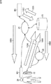
以下、図面を参照して、本発明の実施の形態について説明する。図1は、本発明を適用したサービス提供システム1の構成例を表すブロック図である。この例においては、ユーザ20が、そのユーザの個人関連情報を記憶する携帯可能な小型のコンピュータなどで構成されるPK(Personal Key)22を携帯している。ここで、個人関連情報とは、単に、名前、住所などそのユーザを特定するための情報だけでなく、嗜好情報、認証情報、点数情報、他の人からもらった情報などを含む、そのユーザに関連する様々な情報の集合を意味する。
Embodiments of the present invention will be described below with reference to the drawings. FIG. 1 is a block diagram showing a configuration example of a service providing system 1 to which the present invention is applied. In this example, a
PK22は、アクセスポイント25の周囲のエリア41において、RF(Radio Frequency)通信、準静電界通信、光通信などの無線通信により、インターネット21に接続されたアクセスポイント25と通信する。また、PK22は、無線通信などにより近傍の情報機器との通信も行う。PK22は、暗号鍵に基づいて情報を暗号化する暗号化機能を有しており、暗号鍵の鍵データは必要に応じてSB(Secure Button)26に記憶される。SB26は通信機能を有するコンピュータであり、PK22と通信し、鍵データの送受信を行う。
The PK 22 communicates with the
インターネット21には、PK22から、ユーザ20の個人関連情報であるPMD(Personal Meta Data)を、インターネット21を介して取得し、取得したPMDをデータベースとして記憶するpBase(Personal Information Base)23が接続されている。pBase23は、コンピュータで構成され、インターネット21に接続される他の情報処理装置と通信する。なお、pBase23には、PK22(ユーザ20)以外のPK(ユーザ)のPMDも複数記憶されている。
A pBase (Personal Information Base) 23 for acquiring PMD (Personal Meta Data), which is personal related information of the
また、インターネット21には、コンピュータなどにより構成され、それぞれ所定の処理を実行するサービスシステム24−1乃至24−3が接続されている。サービスシステム24−1乃至24−3は、インターネット21を介して、PK22またはpBase23からPMDを取得し、取得したPMDに基づいて、所定のプログラムを実行することにより、情報提供、買い物代金の決済などのサービスをユーザに提供する。
The
例えば、サービスシステム24−1は、パーソナルコンピュータにWebページ、音楽情報など提供するコンテンツサーバとされ、サービスシステム24−2は、クレジットカードによる決済などを行うクレジットカード処理サーバとされ、サービスシステム24−3は、ユーザ20に対して行われるコミュニケーションを制御するコミュニケーションサーバとされる。また、アクセスポイント25も、PK22との通信を行うサービスシステム24−4に包含される。なお、これらを個々に区別する必要がない場合、まとめてサービスシステム24と称する。
For example, the service system 24-1 is a content server that provides Web pages, music information, and the like to a personal computer, and the service system 24-2 is a credit card processing server that performs payment using a credit card.
この例では、サービスシステム24−1乃至24−4が表示されているが、実際には、多数のサービスシステムが存在する。また、サービスシステム24は、パーソナルコンピュータ、サーバなどに限られるものではなく、コンソール端末、または各種のコンシューマエレクトロニクス機器(CE機器)などにより構成されるようにしてもよい。さらに、サービスシステム24は、インターネット21に接続されるものに限られることはなく、通信機能を有するものであれば、どこに設置されていてもよい。なお、PK22とサービスシステム24は、インターネット21を介さずに、直接通信することも可能である。
In this example, service systems 24-1 to 24-4 are displayed, but there are actually many service systems. The
図2は、PK22の構成例を示すブロック図である。CPU(Central Processing Unit)101は、ROM(Read Only Memory)102に記憶されているプログラム、または記憶部108からRAM(Random Access Memory)103にロードされたプログラムに従って各種の処理を実行する。RAM103にはまた、CPU101が各種の処理を実行する上において必要なデータなども適宜記憶される。
FIG. 2 is a block diagram illustrating a configuration example of the PK22. A CPU (Central Processing Unit) 101 executes various processes according to a program stored in a ROM (Read Only Memory) 102 or a program loaded from a
CPU101、ROM102、およびRAM103は、バス104を介して相互に接続されている。このバス104にはまた、入出力インタフェース105も接続されている。
The
入出力インタフェース105には、スイッチまたはボタンなどよりなる入力部106、およびドットマトリックスディスプレイ、スピーカ、振動モータなどにより構成され、画像、音声、点字または振動などによりユーザに提示する情報を出力する出力部107が接続されている。さらに、入出力インタフェース105には、ハードディスク、またはEEPROM(Electrically Erasable and Programmable Read Only Memory)などにより構成される記憶部108、無線送受信装置などにより構成される通信部109が接続されている。なお、通信部109は、RF通信(電磁波通信)、準静電界通信、光通信など通信方法に応じて、複数設けられるようにしてもよい。
The input /
RF(Radio Frequency)通信は、IEEE802.11bに代表される無線LANなどの通信であり、この通信により、所定のアクセスポイント(ハブ)の周囲およそ数十メートルで通信することができる。準静電界通信は、人体近傍に、遠隔伝播せず閉域のみに成立する物理的性質(エバネッセント性)をもつ閉じた静電的な情報空間を形成する通信方式であり、この通信により、人体が微弱な静電気のアンテナとなり人体の周囲およそ数センチメートル、または数メートルの限られた空間で通信することが可能となる。これにより、例えば、PK22を携帯したユーザが、歩行しながら、PK22に通信させることができる。 The RF (Radio Frequency) communication is a communication such as a wireless LAN represented by IEEE802.11b. By this communication, communication can be performed around several tens of meters around a predetermined access point (hub). Quasi-electrostatic field communication is a communication method that forms a closed electrostatic information space in the vicinity of the human body that does not propagate remotely and has a physical property (evanescent) that is established only in the closed area. It becomes a weak electrostatic antenna and can communicate in a limited space of several centimeters or a few meters around the human body. Thereby, for example, the user carrying the PK22 can communicate with the PK22 while walking.
勿論、通信部109は、イーサネット(登録商標)などに代表される有線の電気的通信または赤外線などの光通信を行うものとすることも可能である。
Of course, the
入出力インタフェース105には、必要に応じてドライブ110が接続され、ドライブ110には、本発明のプログラムが記録された記録媒体として、例えば、リムーバブルメディア111が装着され、それらから読み出されたコンピュータプログラムが、必要に応じて記憶部108にインストールされる。
A
図3は、pBase23の構成例を示すブロック図である。その構成は、図2に示したPK22の構成と同様であり、図3のCPU121乃至リムーバブルメディア131は、図2のCPU101乃至リムーバブルメディア111に対応している。各部の機能は、図2の場合と同様であり、詳細な説明は省略するが、通信部129は、無線送受信装置の他、LANカード、モデムなどの有線による通信装置により構成される。
FIG. 3 is a block diagram illustrating a configuration example of pBase23. The configuration is the same as the configuration of the
また、サービスシステム24も図3と同様の構成であり、同図を適用する。
The
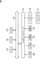
図4は、PK22の記憶部108に記憶されるソフトウェア60の構成例を示すブロック図である。ソフトウェア60には、PK22に保存される個人情報であるPMDをデータベースとして記憶するPMDB67、および通信部109を制御して通信を行う通信モジュール61が含まれている。
FIG. 4 is a block diagram illustrating a configuration example of the
また、ユーザによる、PMDに対するアクセスの許可の指定を受け付けるユーザ制御許可入力モジュール62、サービスシステム24からアクセス要求があったPMDについて、ユーザにアクセス可否を判断させるために、そのPMDを提示する許可項目確認モジュールが含まれている。さらに、サービスシステム24のなりすましを防止するなりすまし防止モジュール64、必要に応じてPMDの変更を行うPMD変更モジュール65が含まれている。DBアクセスモジュール66は、ユーザ制御許可入力モジュール62乃至PMD変更モジュール65の指令(要求)に基づいて、PMDB67にアクセスし、PMDの読み出しまたは変更を行う。
In addition, a user control
PMDB67は、複数のPMDにより構成されるデータベースであり、各PMDは、各サービスシステム24に対応した固有のIDであるサービスIDをキーとして、各情報がディレクトリ状に関連付けられている。サービスID1のディレクトリ(PMD)には、アクセス許可情報、メタデータA−1、メタデータA−2、メタデータA−3、・・・が関連付けられている。
The
アクセス許可情報は、そのディレクトリに関連付けられた情報に対する、サービスシステム24からのアクセスの可否を表す情報であり、ユーザにより設定される。メタデータA−1、メタデータA−2、およびメタデータA−3、・・・は、サービスID1に対応するサービスシステム24において、利用される個人関連情報であり、例えば、サービスID1に対応するサービスシステムが、映画やテレビ番組などのコンテンツを提供するコンテンツサーバである場合、メタデータA−1、メタデータA−2、およびメタデータA−3、・・・には、それぞれ視聴された番組のメタデータが記憶される。その他、PMDには、PK22(ユーザ20)を特定するユーザID、なりすまし防止処理において必要となる合言葉または暗号鍵などの認証情報、視聴された番組に基づくユーザの嗜好情報、およびテレビジョン受像機などを制御する制御情報などが記憶される。
The access permission information is information indicating whether or not the
同様にして、サービスID2のディレクトリにもアクセス許可情報、メタデータB−1、メタデータB−2、メタデータB−3、・・・が関連付けられている。そして、PKが新たに、サービスシステム24を利用する場合、新たなサービスIDが登録され、そのサービスIDに対応するディレクトリが生成される。そして、それぞれのディレクトリがPMDとされ、PMDB67が構成される。なお、PMDの詳細な構成例については、図20を参照して後述する。
Similarly, access permission information, metadata B-1, metadata B-2, metadata B-3,... Are also associated with the directory of service ID2. When the PK newly uses the
図5は、PK22にサービスシステム24に対応するサービスIDを、最初に登録(初期登録)するときの処理の流れを示すアローチャートである。ステップS1において、サービスシステム24は、PK22に対して、登録要求、サービスIDおよび、そのサービスシステムの読み出し変更対象となるメタデータを表す情報を送信し、ステップS21において、PKの通信モジュール61により、これが受信される。
FIG. 5 is an arrow chart showing a processing flow when the service ID corresponding to the
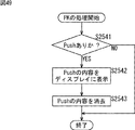
ステップS22において、通信モジュール61は、許可項目確認モジュール63に受信内容を転送する。許可項目確認モジュール63は、ステップS42において、読み出し変更対象となるメタデータをユーザに提示する。このとき、例えば、メタデータの内容が、ドットマトリックスディスプレイ等に文字または図形等が表示されるか、スピーカを通じて音声により内容を読み上げられる。あるいはまた、メタデータの内容が、機械的機構により点字として生成され、提示されるか、振動によりモールス信号等の信号が生成され、提示されるようにしてもよい。
In step S <b> 22, the
ステップS43において、許可項目確認モジュール63は、ユーザ制御許可入力モジュール62に対して、確認要求を出力し、ステップS61においてこれが取得される。ステップS62において、ユーザ制御許可入力モジュール62は、ステップS42で提示された読み出し変更対象メタデータに対するアクセスを、ユーザが拒否したか否かを判定し、拒否したと判定された場合、拒否信号を出力し、ステップS23において、通信モジュール61によりこれが受信される。ステップS24において、通信モジュール61は、拒否信号をサービスシステム24に送信し、ステップS2でこれが受信される。
In step S43, the permission
一方、ステップS62において、ステップS42で提示された読み出し変更対象メタデータに対するアクセスを、ユーザが拒否していないと判定された場合、ユーザ制御許可入力モジュール62は、ステップS63において、ユーザの指定に基づいて、読み出し変更対象となるメタデータのそれぞれについて、例えば、「読み出しと変更を許可」、「読み出しのみ許可」などの情報を設定し、これらの情報がアクセス許可情報(図4)としてPMDB67に記憶される。ステップS64において、ユーザ制御許可入力モジュール62は、アクセス許可情報が設定されたことを、許可項目確認モジュール63に対して通知し、ステップS44において、これが取得される。ステップS45において、許可項目確認モジュール63は、なりすまし防止モジュール64に対して、確認コードの生成要求を行い、ステップS81において、なりすまし防止モジュール64により、これが取得される。
On the other hand, if it is determined in step S62 that the user has not denied access to the read change target metadata presented in step S42, the user control
ステップS82において、なりすまし防止モジュール64は、確認コードを生成する。確認コードは、PK22とサービスシステム24が、次回通信を行うときのなりすまし防止方法を表すコードである。すなわち、不正なユーザ、または通信を盗聴した第3者などが、自身のアドレス、またはIDなどを詐称するなどして、PK22、またはサービスシステム24になりすましていないかを、互いに確認するための方法を表すコードである。
In step S82, the
ここで、なりすまし防止方法としては、例えば、合言葉による認証、公開鍵により暗号化された情報による認証、共通鍵により暗号化された情報による認証などが採用されるが、サービスシステム24との通信において、どれだけの安全性が要求されるのか、どの程度、頻繁になりすまし防止のためのチェックをおこなうか、暗号鍵の管理方法の安全性と平易さ、暗号化と復号化における演算量、などを考慮して、そのサービスシステム24との通信において、最適ななりすまし防止方法が選択され、そのなりすまし防止方法に対応する確認コードが生成される。なお、なりすまし防止の処理については、図6と図7を参照して後述する。
Here, as the spoofing prevention method, for example, authentication by secret words, authentication by information encrypted by a public key, authentication by information encrypted by a common key, and the like are adopted, but in communication with the
ステップS82において、なりすまし防止モジュール64は、確認コードを、通信モジュール61に対して出力し、ステップS25において、通信モジュール61によりこれが取得される。ステップS26において、通信モジュール61は、ステップS25で取得された確認コードをサービスシステム24に送信し、ステップS3においてこれが受信される。
In step S82, the
なお、このとき、PK22(のユーザ)を特定するユーザIDも合わせてサービスシステム24により受信され、サービスシステム24は、ユーザIDと、そのユーザIDに対応する確認コードを記憶する。ユーザIDは、サービスシステム24がPK22(のユーザ)を特定できるものであれば、どのような形式でもよい。例えば、ユーザIDが所定の数字の組み合わせにより構成されるようにしてもよいし、所定の文字列で構成されるようにしてもよい。また、複数のサービスシステム24に対応して、それぞれ別のユーザIDが生成されるようにしてもよい。
At this time, the
ステップS46において、許可項目確認モジュール63は、DBアクセスモジュール66に対して、サービスID登録要求を出力し、ステップS101において、DBアクセスモジュール66により、これが受信される。ステップS102において、DBアクセスモジュール66は、図9を参照して後述するサービスID登録処理を実行し、これによりサービスIDが登録され、サービスIDに対応するPMDが生成される。
In step S46, the permission
このようにして、PK22において、サービスシステム24に対応するサービスIDが登録される。サービスIDが登録されるとき、そのサービスシステム24により、読み出される、または変更されるPMDのメタデータがユーザに提示されるようにしたので、ユーザは、より安心してサービスを受けることができる。また、PK22が、そのサービスIDが登録されたサービスシステム24と次回に通信するときは、確認コードに基づいて、なりすまし防止処理を行うことができる。同様に、サービスシステム24が、そのユーザIDが登録されたPK22と次回に通信するときは、確認コードに基づいて、なりすまし防止処理を行うことができる。
In this way, the service ID corresponding to the
次に、図6と図7を参照して、PK22が、既にサービスIDが登録されているサービスシステム24との通信を行うときのなりすまし防止の処理について説明する。
Next, with reference to FIG. 6 and FIG. 7, a process for preventing spoofing when the
図6は、PK22とサービスシステム24の間のなりすまし防止方法として、合言葉による認証が採用されている場合のなりすまし防止の処理の流れを説明するアローチャートである。この例では、PK22において、サービスシステム24がなりすましではないことを確認し、その後サービスシステム24において、PK22がなりすましではないことを確認する。そして、PK22とサービスシステム24において、それぞれがなりすましではないことが確認できた後、PMDの読み出し、または変更の処理を行う。
FIG. 6 is an arrow chart for explaining the flow of processing for preventing spoofing when authentication by secret words is adopted as a method for preventing spoofing between the
合言葉は、所定の文字列またはコードなどであり、PK22において、サービスIDの登録時に、サービスIDに対応する合言葉として、サービスシステム24を認証するための合言葉(サービス合言葉)とPKを認証するための合言葉(PK合言葉)が生成され、PMDB67に記憶されている。また、サービスID登録時にサービス合言葉とPK合言葉が、サービスシステム24にも送信され、サービスシステム24の記憶部128の中のデータベースに、サービス合言葉とPK合言葉が、PK22のユーザIDと関連付けられて記憶されている。
The secret word is a predetermined character string or code, etc., and at the time of registration of the service ID in the
ステップS201において、サービスシステム24は、接続要求、サービスID、合言葉をPK22に送信し、ステップS221において、PK22の通信モジュールによりこれが受信される。なお、ステップS201においては、上述したサービス合言葉が送信される。ステップS222において、通信モジュール61は、ステップS221で受信した内容をなりすまし防止モジュール64に転送し、ステップS281においてこれが受信される。
In step S201, the
ステップS282において、なりすまし防止モジュール64は、図10を参照して後述するサービスIDマッチング処理を実行し、サービスIDの認識を行い、ステップS283において、DBアクセスモジュール66に対して、サービスIDに対応するユーザIDと合言葉の要求を通知し、ステップS301において、DBアクセスモジュール66によりこれが取得される。なお、ステップS282のサービスIDマッチング処理はDBアクセスモジュール66で行われるようにしてもよい。
In step S282, the
ステップS302においてDBアクセスモジュール66は、PMDB67からサービスIDに対応するサービス合言葉、PK合言葉、およびユーザIDを読み出し、なりすまし防止モジュール64に出力する。なりすまし防止モジュール64は、ステップS284で取得されたサービス合言葉と、ステップS281で取得された合言葉を比較し、合言葉が一致しないと判定された場合、サービスシステム24が、なりすましである可能性があると判定し、通信モジュール61に対して、通信の拒否を表す拒否信号を通知し、ステップS223において、通信モジュール61により、これが取得される。ステップS224において、通信モジュール61は、拒否信号をサービスシステム24に送信し、ステップS202において、サービスシステム24により、これが受信される。
In step S302, the
このように、通信を開始するとき、サービスシステム24からサービスIDに対応する合言葉が送信されなかった場合、PK22により、その通信は拒否される。
As described above, when the password corresponding to the service ID is not transmitted from the
一方、ステップS285において、サービス合言葉が一致すると判定された場合、なりすまし防止モジュール64は、ステップS286において、サービスシステム24が、なりすましでないことが確認できたことを表すコード(OK)と、ユーザID、ステップS284で取得されたPK合言葉を、通信モジュール61に出力し、ステップS225において、通信モジュール61により、これが取得される。ステップS226において、通信モジュール61は、ステップS225で取得された情報を、サービスシステム24に送信し、ステップS203において、サービスシステム24によりこれが受信される。
On the other hand, if it is determined in step S285 that the service passwords match, the
ステップS204において、サービスシステム24は、ステップS203で受信されたユーザIDに対応するPK合言葉を、自身のデータベースから読み出し、ステップS203で受信された合言葉と比較し、合言葉が一致しているか否かを判定する。ステップS204において、合言葉が一致しないと判定された場合、PK22が、なりすましである可能性があると判定し、サービスシステム24は、通信の拒否を表す拒否信号をPK22に送信する。PK22では、通信モジュール61を介して、なりすまし防止モジュール64によりステップS287で、これが受信される。
In step S204, the
このように、通信を開始するとき、PK22からユーザIDに対応する合言葉が送信されなかった場合、サービスシステム24により、その通信は拒否される。
As described above, when the password corresponding to the user ID is not transmitted from the
一方、ステップS204において、合言葉が一致すると判定された場合、サービスシステム24は、PK22がなりすましでないことが確認できたと判定し、ステップS205において、PK22に対してPMDの読み出し要求を送信し、ステップS227において、PK22の通信モジュール61により、これが受信される。ステップS228において、通信モジュール61は、ステップS227で受信された内容を、DBアクセスモジュール66に対して出力し、ステップS303において、DBアクセスモジュール66により、これが取得される。
On the other hand, if it is determined in step S204 that the secret words match, the
ステップS304において、DBアクセスモジュール66は、サービスシステム24から読み出し要求のあったPMD(のメタデータ)が、サービスシステム24に対応するサービスIDに対して、読み出しが許可されているPMDであるか否かを確認し、読み出しが許可されているPMDである場合、そのPMDをPMDB67から読み出す。そして、ステップS305において、DBアクセスモジュール66は、読み出したPMDを通信モジュール61に対して出力し、ステップS229において、通信モジュール61により、これが取得される。
In step S304, the
ステップS230において、通信モジュール61は、ステップS229で取得された情報を、サービスシステム24に対して送信し、ステップS206において、サービスシステム24により、これが受信される。
In step S230, the
ステップS207において、サービスシステム24は、ステップS206で取得されたPMDに基づいて、各種の処理(サービス対応処理)を実行する。ステップS207の処理の結果、PMDの変更が必要となる場合、サービスシステム24は、ステップS208において、PMDの内容を変更し、PK22に対して送信し、ステップS231において、PK22の通信モジュール61により、これが受信される。
In step S207, the
ステップS232において、通信モジュール61は、ステップS231で受信された情報をDBアクセスモジュール66に対して出力し、ステップS306においてDBアクセスモジュール66によりこれが取得される。そして、ステップS307において、DBアクセスモジュール66は、ステップS306で取得されたPMDが、サービスシステム24に対応するサービスIDに対して変更許可のあるPMDであるか否かを確認し、変更許可のあるPMDである場合、PMDB67の中の対応するPMDの変更を行う(変更内容に対応して更新する)。
In step S232, the
このようにすることで、PMDの読み出し、または変更を行う前に、なりすましの確認することができるので、安全なサービスを提供することができる。さらに、PK22によるサービスシステム24のなりすましの確認と、サービスシステム24によるPK22のなりすましの確認が行われるようにしたので、より安全なサービスを提供することができる。
By doing so, impersonation can be confirmed before PMD is read or changed, so that a safe service can be provided. Further, since confirmation of impersonation of the
次に図7を参照して、PK22が、既にサービスIDが登録されているサービスシステム24との通信を行うときのなりすまし防止の処理の別の例について説明する。図7は、PK22とサービスシステム24の間のなりすまし防止方法として、公開鍵により暗号化された情報による認証が採用されている場合のなりすまし防止の処理の流れを説明するアローチャートである。
Next, another example of the spoofing prevention process when the
この例においても、PK22において、サービスシステム24がなりすましではないことを確認し、その後サービスシステム24において、PK22がなりすましではないことを確認する。そして、PK22とサービスシステム24において、それぞれがなりすましではないことが確認できた後、PMDの読み出し、または変更の処理を行う。
Also in this example, the
また、この例においては、PK22とサービスシステム24は、RSAなどの公開鍵方式の暗号アルゴリズムによる情報の暗号化または複合化の処理を実行する機能を有しており、サービスIDを登録するとき、PK22により、サービスシステム24の公開鍵が、サービスシステム24のサービスIDに関連付けられてPMDB67に記憶されており、サービスシステム24により、PK22の公開鍵が、PK22のユーザIDに関連づけられて記憶部128の中のデータベースに記憶されている。PK22とサービスシステム24の秘密鍵は、それぞれの記憶部108または128に記憶されている。
Further, in this example, the
ステップS401において、サービスシステム24は、接続要求とサービスIDをPK22に送信し、ステップS421において、PK22の通信モジュールによりこれが受信される。ステップS422において、通信モジュール61は、ステップS421で受信した情報をなりすまし防止モジュール64に転送し、ステップS481においてこれが受信される。
In step S401, the
ステップS482において、なりすまし防止モジュール64は、図10を参照して後述するサービスIDマッチング処理を実行し、サービスIDの認識を行い、ステップS483において、DBアクセスモジュール66に対して、サービスIDに対応するユーザID、PKの秘密鍵、およびサービスシステム24の公開鍵の要求を通知し、ステップS501において、DBアクセスモジュール66によりこれが取得される。なお、ステップS482のサービスIDマッチング処理は、DBアクセスモジュール66において実行されるようにしてもよい。
In step S482, the
ステップS502において、DBアクセスモジュール66は、サービスIDに対応するサービスシステム24の公開鍵と、PKの秘密鍵をPMDB67から読み出し、なりすまし防止モジュール64に対して出力し、ステップS484において、なりすまし防止モジュール64により、これが取得される。
In step S502, the
ステップS485において、なりすまし防止モジュール64は、サービスシステム24を認証するため、所定のコードで構成されるチャンレンジコードを生成し、チャレンジコードをサービスIDに対応する公開鍵(サービスシステム24の公開鍵)で暗号化し、暗号化されたチャレンジコードとユーザIDを通信モジュール61に対して出力し、ステップS423において、通信モジュール61により、これが取得される。ステップS424において、通信モジュール61は、ステップS423で取得された情報をサービスシステム24に送信し、ステップS402において、サービスシステム24により、これが受信される。
In step S485, the
ステップS403において、サービスシステム24は、ステップS402で受信された、暗号化されたチャレンジコードをサービスシステム24の秘密鍵により復号し、復号されたチャレンジコードをレスポンスコードとし、レスポンスコードをユーザIDに対応する公開鍵(PK22の公開鍵)で暗号化してPK22に対して送信し、ステップS425において、PK22の通信モジュール61により、これが受信される。
In step S403, the
ステップS426において、通信モジュール61は、ステップS425で受信された、暗号化されたレスポンスコードを、なりすまし防止モジュール64に対して出力し、ステップS486において、なりすまし防止モジュール64により、これが取得される。
In step S426, the
ステップS487において、なりすまし防止モジュール64は、ステップS486で取得された、暗号化されたレスポンスコードをPK22の秘密鍵で複合化し、ステップS485で生成したチャレンジコードと比較して、チャレンジコードとレスポンスコードが一致しているか否かを判定し、チャレンジコードとレスポンスコードが一致しないと判定された場合、サービスシステム24が、なりすましである可能性があると判定し、通信モジュール61に対して、通信の拒否を表す拒否信号を通知し、ステップS427において、通信モジュール61により、これが取得される。ステップS428において、通信モジュール61は、拒否信号をサービスシステム24に送信し、ステップS404において、サービスシステム24により、これが受信される。
In step S487, the
このように、通信を開始するとき、PK22からチャレンジコードが送信され、サービスシステム24からチャレンジコードと一致するレスポンスコードが返信されなかった場合、PK22により、その通信は拒否される。
Thus, when communication is started, if a challenge code is transmitted from the
一方、ステップS487において、チャレンジコードとレスポンスコードが一致すると判定された場合、なりすまし防止モジュール64は、ステップS488において、サービスシステム24がなりすましでないことが確認できたことを表すコード(OK)を、通信モジュール61を介して、サービスシステム24に送信し、ステップS405において、サービスシステム24によりこれが受信される。
On the other hand, if it is determined in step S487 that the challenge code and the response code match, the
ステップS406において、サービスシステム24は、PK22を認証するため、所定のコードにより構成されるチャレンジコードを生成し、チャレンジコードをユーザIDに対応する公開鍵(PK22の公開鍵)で暗号化し、暗号化されたチャレンジコードをPK22に対して送信し、ステップS429において、PK22の通信モジュール61によりこれが受信される。ステップS430において、通信モジュール61は、ステップS429で受信された情報をなりすまし防止モジュール64に対して出力し、ステップS489において、なりすまし防止モジュール64により、これが取得される。
In step S406, the
ステップS490において、なりすまし防止モジュール64は、ステップS489で受信された、暗号化されたチャレンジコードをPK22の秘密鍵で復号し、復号されたチャレンジコードをレスポンスコードとし、レスポンスコードをサービスIDに対応する公開鍵(サービスシステム24の公開鍵)で暗号化し、通信モジュール61に対して出力し、ステップS431において、通信モジュール61により、これが取得される。ステップS432において、通信モジュール61は、ステップS431で取得された情報をサービスシステム24に対して送信し、ステップS407において、サービスシステム24によりこれが受信される。
In step S490, the
ステップS408において、サービスシステム24は、ステップS407で受信された、暗号化されたレスポンスコードを、サービスシステム24の秘密鍵で復号し、復号されたレスポンスコードが、ステップS406で生成されたチャレンジコードと一致するか否かを判定し、チャレンジコードとレスポンスコードが一致しないと判定された場合、PK22が、なりすましである可能性があると判定し、PK22に対して、通信の拒否を表す拒否信号を送信し、ステップS433で、PK22の通信モジュール61により、これが受信される。ステップS434において、通信モジュール61は、ステップS433で受信された情報を、なりすまし防止モジュール64に対して送信し、ステップS491において、なりすまし防止モジュール64により、これが取得される。
In step S408, the
このように、通信を開始するとき、サービスシステム24からチャレンジコードが送信され、PK22からチャレンジコードと一致するレスポンスコードが返信されなかった場合、サービスシステム24により、その通信は拒否される。
Thus, when communication is started, if a challenge code is transmitted from the
一方、ステップS408において、チャレンジコードとレスポンスコードが一致すると判定された場合、サービスシステム24は、PK22がなりすましでないことが確認できたと判定し、ステップS409において、PK22に対してPMDの読み出し要求を送信し、ステップS435において、PK22の通信モジュール61により、これが受信される。ステップS436において、通信モジュール61は、ステップS435で受信された情報を、DBアクセスモジュール66に対して出力し、ステップS503において、DBアクセスモジュール66により、これが取得される。
On the other hand, if it is determined in step S408 that the challenge code and the response code match, the
ステップS504において、DBアクセスモジュール66は、サービスシステム24から読み出し要求のあったPMD(のメタデータ)が、サービスシステム24に対応するサービスIDに対して、読み出しが許可されているPMDであるか否かを確認し、読み出しが許可されているPMDである場合、そのPMDをPMDB67から読み出す。そして、ステップS505において、DBアクセスモジュール66は、読み出したPMDを通信モジュール61に対して出力し、ステップS437において、通信モジュール61により、これが取得される。
In step S504, the
ステップS438において、通信モジュール61は、ステップS437で取得された情報を、サービスシステム24に対して送信し、ステップS410において、サービスシステム24により、これが受信される。
In step S438, the
ステップS411において、サービスシステム24は、ステップS410で取得されたPMDに基づいて、各種の処理(サービス対応処理)を実行する。ステップS411の処理の結果、PMDの変更が必要となる場合、サービスシステム24は、ステップS412において、PMDの内容を変更し、PK22に対して送信し、ステップS439において、PK22の通信モジュール61により、これが受信される。
In step S411, the
ステップS440において、通信モジュール61は、ステップS439で受信された情報をDBアクセスモジュール66に対して出力し、ステップS506においてDBアクセスモジュール66によりこれが取得される。そして、ステップS507において、DBアクセスモジュール66は、ステップS506において取得されたPMDが、サービスシステム24に対応するサービスIDに対して変更許可のあるPMDであるか否かを確認し、変更許可のあるPMDである場合、PMDB67の中の対応するPMDの変更を行う(変更内容に更新する)。
In step S440, the
このようにすることで、PMDの読み出し、または変更を行う前に、PK22とサービスシステム24が、互いになりすましでないことを確認することができるので、安全なサービスを提供することができる。また、PK22またはサービスシステム24を認証するためのチャレンジコードとレスポンスコードは、それぞれPK22とサービスシステム24の公開鍵と秘密鍵により、暗号化または復号化されるので、仮に、第三者に通信が傍受されても、チャレンジコードとレスポンスコードの内容は、秘匿されるので、より確実になりすましを防止することができる。
In this way, it is possible to confirm that the
なお、図7においては、公開鍵方式の暗号アルゴリズムにより、チャレンジコードとレスポンスコードを暗号化する例について説明したが、PK22とサービスシステム24が、公開鍵方式の暗号アルゴリズムではなく、共通鍵方式の暗号アルゴリズムで、情報の暗号化または複合化の処理を実行する機能を有し、PK22とサービスシステム24において、互いに共通の暗号鍵が保持され、チャレンジコードとレスポンスコードが、その鍵で暗号されることにより通信が行われるようにしてもよい。
In FIG. 7, an example in which the challenge code and the response code are encrypted by a public key encryption algorithm has been described. However, the
この場合、サービスIDの登録を行うとき、PK22により、そのサービスIDに対応する暗号鍵が生成され、サービスIDに関連付けられてPMDB67に記憶されると同時に、同じ暗号鍵が、サービスシステム24に送信され、PK22のユーザIDに対応付けられてサービスシステム24のデータベースに記憶される。
In this case, when the service ID is registered, an encryption key corresponding to the service ID is generated by the
暗号鍵が漏洩した場合、PK22とサービスシステム24は、暗号鍵を変更する必要がある。例えば、あるサービスシステムの公開鍵方式の暗号アルゴリズムで用いられる秘密鍵が漏洩した場合、そのサービスシステムを利用する多数のPKにおいて、サービスIDに対応する公開鍵を変更する必要がある。しかし、PK22とサービスシステム24において、互いに共通の暗号鍵が保持されるようにすれば、暗号鍵が漏洩した場合でも、その鍵を使うPK22とサービスシステム24の暗号鍵のみ変更するだけで、対処することができる。
When the encryption key is leaked, the
なお、図7においては、チャレンジコードとレスポンスコードが暗号化される例について説明したが、通信内容の全てが暗号化されるようにしてもよい。 In addition, although the example in which the challenge code and the response code are encrypted has been described with reference to FIG. 7, all the communication contents may be encrypted.
また、図7の例では、秘密鍵(または共通鍵)がPK22の中(PMDB67)に保管される例について説明したが、PK22とは異なる機器、例えば、図1のSB26に保管されるようにしてもよい。この場合、サービスシステム24と通信を行うに先立って、PK22とSB26が通信を行い、SB26からPK22に秘密鍵が送信される(このとき、SBはPKに対して、1つのサービスシステムとして通信する)。PKは、一定時間経過すると秘密鍵を消去する処理を行い、必要なときには、都度、SB26と通信して秘密鍵を取得する。
In the example of FIG. 7, the example in which the secret key (or common key) is stored in the PK22 (PMDB 67) has been described. However, the secret key (or common key) is stored in a device different from the PK22, for example, the
この場合のPK22の鍵管理処理について、図8を参照して説明する。この処理は、PK22が、サービスシステム24との通信を行うとき、図7に示されるようななりすまし防止の処理が行われるのに先立って実行される。
The key management process of the
ステップS681において、PK22のCPU101は、SB26から鍵を取得し、記憶部108に記憶する。ステップS682において、CPU101は、所定の時間(例えば、1時間)が経過したか否かを判定し、所定の時間が経過したと判定されるまで待機する。ステップS682において、所定の時間が経過したと判定された場合、ステップS683において、記憶部108に記憶されている鍵を消去する。
In step S <b> 681, the
このようにして、鍵の管理が行われる。このようにすることで、例えば、PK22が盗まれた場合でも、秘密鍵が漏洩することを防止することができる。
In this way, key management is performed. By doing so, for example, even when the
次に、図9を参照して、図5のステップS102のサービスID登録処理の詳細について説明する。多くの場合、サービスシステム24は、インターネット21に接続されたサーバである。この処理は、図5のステップS102において、サービスシステム24を特定する情報として、サービスシステム24を構成するサーバのURI(Uniform Resource Identifiers)が取得された場合、実行される。
Next, details of the service ID registration process in step S102 of FIG. 5 will be described with reference to FIG. In many cases, the
ステップS801において、DBアクセスモジュール66は、URIを取得する。ステップS802において、DBアクセスモジュール66は、マスクがあるか否かを判定する。マスクは、URIの中の所定のセグメントを示す情報であり、例えば、ユーザにより、予め設定されている。
In step S801, the
URIは、インターネット21でのユニークなアドレスとして管理されており、全世界でのさまざまなサーバに、例えば、「http://aaa.bbb.ccc」のようなネーミングが行われている。ここで、「http://aaa.bbb.」(または「http://aaa.」)の部分は、通常そのサーバが提供するサービスに対応する会社名などを示し、cccの部分は、そのサービスの内容に応じて変化する。例えば、ユーザが、特定の会社が行うさまざまなサービスすべてに対して、PMDの読み出しまたは変更を許可する場合、「http://aaa.bbb.」の部分のみを参照してサービスシステム24を特定すればよい。このような場合、マスクとして、下位1セグメント(「ccc」の部分)が設定される。
The URI is managed as a unique address on the
ステップS802において、マスクがあると判定された場合、ステップS804に進み、DBアクセスモジュール66は、サービスIDとして、マスクされた部分を取り除いたURI(「http://aaa.bbb.」の部分)を登録する。ステップS802において、マスクがないと判定された場合、ステップS803に進み、DBアクセスモジュール66は、サービスIDとしてURIをそのまま(「http://aaa.bbb.ccc」)登録する。
If it is determined in step S802 that there is a mask, the process proceeds to step S804, and the
ステップS803またはS804の処理の後、ステップS805に進み、DBアクセスモジュール66は、サービスIDと、そのサービスIDに対応するサービスシステム24において、利用される個人関連情報を関連づけて、そのサービスIDに対応するPMDを生成する。
After the processing of step S803 or S804, the process proceeds to step S805, and the
このようにして、サービスIDが登録される。 In this way, the service ID is registered.
次に、図10を参照して、図6のステップS282、または図7のステップS482のサービスIDマッチング処理の詳細について説明する。なお、この例では、サービスIDマッチング処理が、DBアクセスモジュール66により実行されるものとする。
Next, details of the service ID matching process in step S282 in FIG. 6 or step S482 in FIG. 7 will be described with reference to FIG. In this example, it is assumed that the service ID matching process is executed by the
ステップS841において、DBアクセスモジュール66は、URIを取得する。ステップS842において、DBアクセスモジュール66は、URIをサービスIDと同じ長さに切り出す。このとき、例えば、URIとして「http://aaa.bbb.ccc」が取得された場合、「http://aaa.bbb.」の部分が切り出される。ステップS843において、DBアクセスモジュール66は、ステップS842で切り出されたURIを登録されたサービスIDと比較する。
In step S841, the
ステップS844において、DBアクセスモジュール66は、ステップS843における比較の結果、サービスIDと一致したか否かを判定し、一致しないと判定された場合、ステップS846に進み、登録されたサービスIDを全てチェックしたか否かを判定し、まだ、全てチェックしていないと判定された場合、ステップS847に進み、ステップS842で切り出されたURIを次のサービスIDと比較し、ステップS844に戻る。
In step S844, the
ステップS844において、ステップS843における比較の結果、サービスIDと一致したと判定された場合、ステップS845に進み、一致したサービスIDを、サービスシステム24を特定するサービスIDとして認識する。
If it is determined in step S844 that the service ID matches the service ID as a result of the comparison in step S843, the process advances to step S845 to recognize the matched service ID as a service ID that identifies the
ステップS846において、登録されたサービスIDを全てチェックしたと判定された場合、ステップS848に進みDBアクセスモジュール66は、このサービスの拒否を通知する。
If it is determined in step S846 that all registered service IDs have been checked, the process proceeds to step S848, and the
このようにして、サービスIDの認識が行われる。 In this way, the service ID is recognized.
ところで、上述したようにPK22には、PMDとして個人関連情報が記憶されており、仮にPK22を盗まれても、悪用されないように、PK22の内部に保存されたPMDが暗号化されて秘匿されることが好ましい。
By the way, as described above, personal information is stored in the
例えば、PMDをPK22の公開鍵で暗号化しておいて、必要に応じて秘密鍵を用いて復号するようにしてもよい。秘密鍵は、SBに保管されているので、PK22とSBの通信が途絶えた場合には、PKの中に秘密鍵がないことになり、PMDを読み出したり変更したりすることができない。
For example, PMD may be encrypted with the public key of PK22 and decrypted using a secret key as necessary. Since the secret key is stored in the SB, if the communication between the
あるいはまた、PK22が、ユーザ20を認証し、正当なユーザ20であると確認された場合だけ、PMDが利用可能とされるようにしてもよい。
Alternatively, PMD may be made available only when the
例えば、一定の時間内に、ワンタイムパスワード(固定パスワードでもよい)または後述する生体認証により、そのユーザが正当なユーザであることが確認できない場合、PMDの読み出しまたは変更の制御が禁止されるようにしてもよいし、PMDが自動的に消去されるようにしてもよい。PMDが消去された場合、ワンタイムパスワードまたは生体認証により、正当なユーザであることが確認されたとき、pBase23に保存されているPMDを利用して、PK22のPMDが回復される。
For example, if it is not possible to confirm that the user is a valid user by a one-time password (which may be a fixed password) or biometric authentication described later within a certain period of time, PMD read or change control is prohibited. Alternatively, PMD may be automatically deleted. When the PMD is deleted, when it is confirmed by a one-time password or biometric authentication that the user is a valid user, the PMD stored in the
図11は、PK22によるユーザ20の認証方法の例を示す図である。図11Aは、PK22は、ユーザ20が常に携帯するチップ201を検知してユーザの認証を行う例を示す図である。チップ201は、例えば、特定の周波数の電波を常に発信する充分に小さい発信機であり、ユーザ20により常に携帯さている。この場合、PK22には、チップ201が発信する電波を検知するセンサが設けられており、センサは、PK22の入力部106に接続されているものとする。PK22は、予め登録されたチップ201が発信する周波数の電波を検知することによりユーザ20を認証する。
FIG. 11 is a diagram illustrating an example of an authentication method for the
この場合、PK22がユーザ20を認証するユーザ認証処理1について、図12を参照して説明する。この処理は、例えば、PK22の電源がONの状態である間、常に継続して実行される。
In this case, user authentication processing 1 in which the
ステップS901において、PK22のCPU101は、センサにより検知された信号を登録されているチップ201の信号と比較する。ステップS902において、CPU101は、ステップS901の比較の結果、信号が一致したか否かを判定し、一致しないと判定された場合、ステップS901に戻る。
In step S901, the
ステップS902において、信号が一致したと判定された場合、ステップS903に進み、ユーザ認証情報を記憶する。このとき、ユーザ20を認証したことを表す情報が、現在時刻(日時)とともに、ユーザ認証情報として、記憶部108に記憶される。
If it is determined in step S902 that the signals match, the process advances to step S903 to store user authentication information. At this time, information indicating that the
ステップS904において、CPU101は、所定の時間(例えば、1時間)が経過したか否かを判定し、所定の時間が経過したと判定されるまで待機する。ステップS904において、所定の時間が経過したと判定された場合、ステップS905に進み、CPU101は、ユーザ認証情報を削除する。その後、処理は、ステップS901に戻り、それ以降の処理が繰り返し実行される。
In step S904, the
あるいはまた、ユーザの生体的特徴(指紋、声紋、虹彩、歩紋等)を用いた認証、すなわち生体認証が行われるようにしてもよい。図11Bは、ユーザ20の生体的特徴としての歩紋202を検知することで、ユーザ20を認証する例を示す図である。この場合、PK22には、準静電界の変化を検知するセンサが設けられており、センサは、PK22の入力部106に接続されているものとする。PK22は、予め登録されたユーザ20の歩紋を検知することによりユーザ20を認証する。なお、歩紋とは、人が歩行するとき、人体に発生する準静電界の変化パターンであり、このパターンを用いて人を認識することができる(例えば、特開2003−58857 歩行検出方法、歩行検出装置 参照)。
Alternatively, authentication using a user's biometric features (fingerprint, voiceprint, iris, gait, etc.), that is, biometric authentication may be performed. FIG. 11B is a diagram illustrating an example of authenticating the
この場合、PK22がユーザ20を認証するユーザ認証処理2について、図13を参照して説明する。この処理は、例えば、PK22の電源がONの状態である間、常に継続して実行される。
In this case, the
ステップS921において、PK22のCPU101は、センサにより検知された準静電界の変化パターン(歩紋)を登録されているユーザ20の歩紋と比較する。ステップS922において、CPU101は、ステップS921の比較の結果、歩紋が一致したか否かを判定し、一致しないと判定された場合、ステップS921に戻る。
In step S921, the
ステップS922において、歩紋が一致したと判定された場合、ステップS923に進み、ユーザ認証情報を記憶する。このとき、ユーザ20を認証したことを表す情報が、現在時刻(日時)とともに、ユーザ認証情報として、記憶部108に記憶される。
If it is determined in step S922 that the footprints match, the process advances to step S923 to store user authentication information. At this time, information indicating that the
ステップS924において、CPU101は、所定の時間(例えば、1時間)が経過したか否かを判定し、所定の時間が経過したと判定されるまで待機する。ステップS924において、所定の時間が経過したと判定された場合、ステップS925に進み、CPU101は、ユーザ認証情報を削除する。その後、処理は、ステップS921に戻り、それ以降の処理が繰り返し実行される。
In step S924, the
このようにして、所定の時間毎に、PK22によりユーザ20が認証される。以上においては、チップ201または歩紋202によりユーザ20が認証される例について説明したが、ユーザの認証方法は、これに限られるものではない。例えば、PK22を、近傍のパーソナルコンピュータと通信させ、パーソナルコンピュータから入力されるパスワードに基づいて、ユーザが認証されるようにしてもよい。
In this way, the
また、上述したように、PK22においては、ユーザが正当なユーザであることが確認(認証)できない場合、PMDが自動的に消去されるようにすることができる。この場合のPMD管理処理について、図14を参照して説明する。この処理は、PK22において、PMDが必要となる都度、実行される。なお、実行に先立って、PK22のCPU101により、図12のステップS903、または図13のステップS923で記憶されたユーザ認証情報が、記憶部108の中に存在する(ユーザが認証されている)ことが確認される。
Further, as described above, in the
ステップS941において、CPU101は、pBase23と通信し、pBase23からPMDを取得し、記憶部108に記憶する。ステップS942においてCPU101は、ステップS941で、PMDを取得してから所定の時間(例えば、3時間)が経過したか否かを判定し、所定の時間が経過したと判定されるまで待機する。
In step S <b> 941, the
ステップS942において、所定の時間が経過したと判定された場合、ステップS943に進み、CPU101は、ユーザが認証されたか否かを判定する。このとき、図12のステップS903、または図13のステップS923で記憶されたユーザ認証情報が、記憶部108の中に存在するか否かが判定され、ユーザ認証情報が存在する場合、ユーザが認証されたと判定され、ユーザ認証情報が存在しない場合、ユーザが認証されなかったと判定される。ステップS943において、ユーザが認証されたと判定された場合、処理はステップS942に戻り、それ以降の処理が繰り返し実行される。
If it is determined in step S942 that the predetermined time has elapsed, the process advances to step S943, and the
ステップS943において、ユーザが認証されなかったと判定された場合、CPU101は、ステップS944に進み、ステップS941で取得したPMDを記憶部108から消去する。
If it is determined in step S943 that the user has not been authenticated, the
このようにして、PK22において、ユーザが正当なユーザであることが確認(認証)できない場合、PMDが自動的に消去される
In this way, if the
ところで、上述したように、PK22は、ユーザが簡単に持ち運べる小型のコンピュータであり、PK22に、いろいろなインタフェース(例えば、ディスプレイ、タッチパッドなど)を直接配置すると、PK22の大きさが大きくなり、重量も重くなるので、ユーザが簡単に持ち運ぶことができなくなる恐れがある。
By the way, as described above, the
このために、PK22に直接配置されるインタフェースは、できるだけ小さくし、例えば、複雑な情報の入力または出力に用いられるインタフェースとして、PK22の外部にある機器などを利用できることが望ましい。
For this reason, it is desirable that the interface directly arranged on the
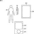
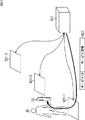
図15は、PK22が外部コンソール221と、外部コンソール222を入力または出力に用いられるインタフェースとして利用する例を示す図である。この場合、PK22は、外部コンソール221および222と、RF通信などの無線通信を行う。外部コンソール221には、項目リスト画面242とプッシュスイッチ241が設けられており、例えば、項目リスト画面242にPMDのリストが表示され、プッシュスイッチ241をユーザが操作することにより、項目リスト画面242に表示されたPMDに対するアクセス許可が指定される。
FIG. 15 is a diagram illustrating an example in which the
外部コンソール222には、タッチパット付ディスプレイ261が設けられており、タッチパッド付ディスプレイ261に表示される操作卓を変化させることができ、例えば、サービスIDに対応して異なるインタフェースが提供される。
The
なお、外部コンソール221または222は、PK22に対して、インタフェースサービスを提供する、サービスシステムの一つとみなすこともできる。この場合、PK22は、外部コンソール221または222の制御コードを記憶するサーバをサービスシステムとして通信を行い、外部コンソール221または222の制御コードを取得する。その後、外部コンソール221または222をサービスシステムとして通信を行い、外部コンソール221または222に制御コードを実装させる。
The
このように、サービスシステム24から、PK22を介して、外部コンソール221などの周辺機器を制御させることにより、図16に示されるように、サービスシステム24に対して、周辺機器(外部コンソール221など)のアドレスなどのアクセスキー280を隠蔽して、サービスの提供を受けることができる。
In this way, by controlling peripheral devices such as the
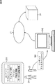
次に、図17を参照して、PK22、pBase23、およびサービスシステム24によりPMDが利用される様子を説明する。PK22は、上述したように、RF通信、準静電界通信、光通信などの無線通信により、インターネット21に接続されたアクセスポイント25と通信し、インターネット21に接続される。このとき、図17Aに示されるように、インターネット21を介してPK22とpBase23が接続され、両者のPMDの内容が比較され、PMDの同期が行われる。例えば、PK22のPMDの内容が更新されている場合、pBase23のPMDも同様に更新され、PMDの同期が行われる。なお、PMDの同期の詳細については後述する。
Next, with reference to FIG. 17, a state in which PMD is used by the
また、例えば、PK22に記憶しきれないPMDをpBase23に記憶させ、図17Bに示されるように、サービスシステム24は、pBase23のPMDを参照し、PK22のユーザに対するサービスを行うようにすることもできる。
Also, for example, PMD that cannot be stored in the PK22 can be stored in the pBase23, and as shown in FIG. 17B, the
あるいはまた、PK22をインターネット21に接続できない場合、pBase23には、PK22のPMDが記憶されているので、図17Cに示されるように、pBase23を、PK22に代わってサービスシステム24と通信させることにより(PK22の代用としてpBase23を利用して)、ユーザはサービスの提供を受けることができる。このような場合、PK22に代わったpBase23とサービスシステム24の間でなりすまし防止の処理が行われ、PMDの送受信が行われる。
Alternatively, if the
図18と図19を参照して、図17Cの場合の、pBase23とサービスシステム24との間の処理の流れを説明する。図18の例では、PK22(のユーザ)に対応するPMDが、pBase23の記憶部128の中のデータベースに記憶されているものとし、サービスシステム24との間で、なりすまし防止方法として、図6の場合と同様に合言葉による認証が採用されているものとする。
With reference to FIG. 18 and FIG. 19, the flow of processing between the pBase 23 and the
同図においては、pBase23において、サービスシステム24がなりすましではないことを確認し、その後サービスシステム24において、pBase23がなりすましではないことを確認する。そして、pBase23とサービスシステム24において、それぞれがなりすましではないことが確認できた後、PMDの読み出し、または変更の処理を行う。また、この例においては、PK合言葉、サービスシステム合言葉、PK22のユーザID、およびサービスシステム24のサービスIDは、やはりPK22のPMDとして、pBase23の記憶部128の中のデータベースに記憶されているものとする。
In the figure, in pBase23, it is confirmed that the
ステップS1101において、サービスシステム24は、接続要求、サービスID、合言葉をpBase23に送信し、ステップS1121において、これが受信される。ステップS1122において、pBase23は、図10を参照して上述したサービスIDマッチング処理を実行し、サービスIDの認識を行い、サービスIDに対応するサービス合言葉、PK合言葉、およびユーザIDを記憶部128のデータベースから読み出す。ステップS1123において、pBase23は、ステップS1121で取得されたサービス合言葉と、記憶部128のデータベースから読み出されたサービス合言葉を比較し、サービス合言葉が一致しないと判定された場合、サービスシステム24が、なりすましである可能性があると判定し、サービスシステム24に対して、通信の拒否を表す拒否信号を送信し、ステップS1102において、これが受信される。
In step S1101, the
このように、通信を開始するとき、サービスシステム24からサービスIDに対応する合言葉が送信されなかった場合、pBase23により、その通信は拒否される。
As described above, when the secret corresponding to the service ID is not transmitted from the
一方、ステップS1123において、サービス合言葉が一致すると判定された場合、pBase23は、ステップS1124において、サービスシステム24がなりすましでないことが確認できたことを表すコード(OK)と、ユーザID、およびユーザIDに対応するPK合言葉を、サービスシステム24に送信し、ステップS1103において、これが受信される。
On the other hand, if it is determined in step S1123 that the service passwords match, the
ステップS1104において、サービスシステム24は、ステップS1103で受信されたユーザIDに対応するPK合言葉を、自身のデータベースから読み出し、ステップS1103で受信されたPK合言葉と比較し、PK合言葉が一致しているか否かを判定する。ステップS1104において、PK合言葉が一致しないと判定された場合、pBase23が、なりすましである可能性があると判定し、サービスシステム24は、通信の拒否を表す拒否信号をpBase23に送信し、ステップS1125で、これが受信される。
In step S1104, the
このように、通信を開始するとき、pBase23からユーザIDに対応する合言葉が送信されなかった場合、サービスシステム24により、その通信は拒否される。
As described above, when the password corresponding to the user ID is not transmitted from the
一方、ステップS1104において、PK合言葉が一致すると判定された場合、サービスシステム24は、pBase23がなりすましでないことが確認できたと判定し、ステップS1105において、pBase23に対してPMDの読み出し要求を送信し、ステップS1126において、これが受信される。ステップS1127において、pBase23は、サービスシステム24から読み出し要求のあったPMDが、サービスシステム24に対応するサービスIDに対して、読み出しが許可されているPMDであるか否かを確認し、読み出しが許可されているPMDである場合、そのPMDを記憶部128のデータベースから読み出す。そして、ステップS1128において、pBase23は、読み出したPMDをサービスシステム24に対して送信し、ステップS1106において、これが受信される。
On the other hand, if it is determined in step S1104 that the PK secrets match, the
ステップS1107において、サービスシステム24は、ステップS1106で取得されたPMDに基づいて、各種の処理(サービス対応処理)を実行する。ステップS1107の処理の結果、PMDの変更が必要となる場合、サービスシステム24は、ステップS1108において、PMDの内容を変更し、pBase23に対して送信し、ステップS1129において、これが受信される。そして、ステップS1130において、pBase23は、ステップS1129において受信されたPMDが、サービスシステム24に対応するサービスIDに対して変更許可のあるPMDであるか否かを確認し、変更許可のあるPMDである場合、記憶部128のデータベースの中の対応するPMDの変更を行う(変更内容に更新する)。
In step S1107, the
このようにして、PMDの読み出し、または変更を行う前に、PK22に代わって、pBase23が、図6の場合と同様に、サービスシステム24との間でなりすましの確認を行うので、安全なサービスを提供することができる。
In this way, before the PMD is read or changed, the
次に図19を参照して、図17Cの場合の、pBase23とサービスシステム24との間の処理の流れの別の例を説明する。この例では、PK22(のユーザ)に対応するPMDが、pBase23の記憶部128に記憶されているものとし、サービスシステム24との間で、なりすまし防止方法として、図7の場合と同様に公開鍵により暗号化された情報による認証が採用されているものとする。
Next, another example of the processing flow between the pBase 23 and the
同図においては、pBase23において、サービスシステム24がなりすましではないことを確認し、その後サービスシステム24において、pBase23がなりすましではないことを確認する。そして、pBase23とサービスシステム24において、それぞれがなりすましではないことが確認できた後、PMDの読み出し、または変更の処理を行う。また、この例においては、pBase23とサービスシステム24は、RSAなどの公開鍵方式の暗号アルゴリズムによる情報の暗号化または複合化の処理を実行する機能を有しているものとする。なお、PK22の秘密鍵、サービスシステム24の公開鍵、PK22のユーザID、およびサービスシステム24のサービスIDは、PK22のPMDとしてpBase23の記憶部128の中のデータベースに記憶されているものとする。
In the figure, in pBase23, it is confirmed that the
ステップS1861において、サービスシステム24は、接続要求とサービスIDをpBase23に送信し、ステップS1881において、これが受信される。ステップS1882において、pBase23は、図10を参照して上述した場合と同様に、サービスIDマッチング処理を実行し、サービスIDの認識を行い、サービスIDに対応するユーザID、サービスシステム24の公開鍵、PK22の秘密鍵を取得する。
In step S1861, the
ステップS1883において、pBase23は、サービスシステム24を認証するため、所定のコードで構成されるチャンレンジコードを生成し、チャレンジコードをサービスIDに対応する公開鍵(サービスシステム24の公開鍵)で暗号化し、暗号化されたチャレンジコードとユーザIDをサービスシステム24に送信し、ステップS1862において、これが受信される。
In step S1883, the
ステップS1863において、サービスシステム24は、ステップS1862で受信された、暗号化されたチャレンジコードをサービスシステム24の秘密鍵により復号し、復号されたチャレンジコードをレスポンスコードとし、レスポンスコードをユーザIDに対応する公開鍵で暗号化してpBase23に対して送信し、ステップS1884において、これが受信される。
In step S1863, the
ステップS1885において、pBase23は、ステップS1884で取得された、暗号化されたレスポンスコードをPK22の秘密鍵で複合化し、ステップS1883で生成したチャレンジコードと比較して、チャレンジコードとレスポンスコードが一致しているか否かを判定し、チャレンジコードとレスポンスコードが一致しないと判定された場合、サービスシステム24が、なりすましである可能性があると判定し、通信の拒否を表す拒否信号をサービスシステム24に送信し、ステップS1864において、これが受信される。
In step S1885, pBase23 decrypts the encrypted response code obtained in step S1884 with the private key of PK22, and compares the challenge code with the response code generated in step S1883. If it is determined that the challenge code and the response code do not match, the
このように、通信を開始するとき、pBase23からチャレンジコードが送信され、サービスシステム24からチャレンジコードと一致するレスポンスコードが返信されなかった場合、pBase23により、その通信は拒否される。
Thus, when communication is started, if a challenge code is transmitted from the
一方、ステップS1885において、チャレンジコードとレスポンスコードが一致すると判定された場合、pBase23は、ステップS1886において、サービスシステム24がなりすましでないことが確認できたことを表すコード(OK)を、サービスシステム24に送信し、ステップS1865において、これが受信される。
On the other hand, if it is determined in step S1885 that the challenge code and the response code match, pBase23 sends a code (OK) indicating that the
ステップS1866において、サービスシステム24は、pBase23(PK22)を認証するため、所定のコードにより構成されるチャレンジコードを生成し、チャレンジコードをユーザIDに対応する公開鍵(PK22の公開鍵)で暗号化し、暗号化されたチャレンジコードをpBase23に対して送信し、ステップS1887において、これが受信される。
In step S1866, the
ステップS1888において、pBase23は、ステップS1887で受信された、暗号化されたチャレンジコードをPKの秘密鍵で復号し、復号されたチャレンジコードをレスポンスコードとし、レスポンスコードをサービスIDに対応する公開鍵で暗号化し、サービスシステム24に対して送信し、ステップS1867において、サービスシステム24によりこれが受信される。
In step S1888, the pBase23 decrypts the encrypted challenge code received in step S1887 with the private key of the PK, sets the decrypted challenge code as a response code, and uses the response code as a public key corresponding to the service ID. It is encrypted and transmitted to the
ステップS1868において、サービスシステム24は、ステップS1867で受信された、暗号化されたレスポンスコードを、サービスシステム24の秘密鍵で復号し、復号されたレスポンスコードが、ステップS1866で生成されたチャレンジコードと一致するか否かを判定し、チャレンジコードとレスポンスコードが一致しないと判定された場合、pBase23が、なりすましである可能性があると判定し、pBase23に対して、通信の拒否を表す拒否信号を送信し、ステップS1889で、これが受信される。
In step S1868, the
このように、通信を開始するとき、サービスシステム24からチャレンジコードが送信され、pBase23からチャレンジコードと一致するレスポンスコードが返信されなかった場合、サービスシステム24により、その通信は拒否される。
Thus, when communication is started, if the challenge code is transmitted from the
一方、ステップS1868において、チャレンジコードとレスポンスコードが一致すると判定された場合、サービスシステム24は、pBase23がなりすましでないことが確認できたと判定し、ステップS1869において、pBase23に対してPMDの読み出し要求を送信し、ステップS1890において、これが受信される。ステップS1891において、pBase23は、サービスシステム24から読み出し要求のあったPMDが、サービスシステム24に対応するサービスIDに対して、読み出しが許可されているPMDであるか否かを確認し、読み出しが許可されているPMDである場合、そのPMDを記憶部128のデータベースから読み出す。そして、ステップS1892において、pBase23は、読み出したPMDをサービスシステム24に対して送信し、ステップS1870において、サービスシステム24により、これが受信される。
On the other hand, if it is determined in step S1868 that the challenge code and the response code match, the
ステップS1871において、サービスシステム24は、ステップS1870で取得されたPMDに基づいて、各種の処理(サービス対応処理)を実行する。ステップS1871の処理の結果、PMDの変更が必要となる場合、サービスシステム24は、ステップS1872において、PMDの内容を変更し、pBase23に対して送信し、ステップS1893において、これが受信される。そして、ステップS1894において、pBase23は、ステップS1893において受信されたPMDが、サービスシステム24に対応するサービスIDに対して変更許可のあるPMDであるか否かを確認し、変更許可のあるPMDである場合、記憶部128のデータベースの中の対応するPMDの変更を行う(変更内容に更新する)。
In step S1871, the
このようにして、PMDの読み出し、または変更を行う前に、PK22に代わって、pBase23が、図7の場合と同様に、サービスシステム24との間でなりすましの確認を行うので、安全なサービスを提供することができる。なお、図19においては、公開鍵方式の暗号アルゴリズムにより、チャレンジコードとレスポンスコードを暗号化する例について説明したが、共通鍵方式の暗号アルゴリズムで、チャレンジコードとレスポンスコードが、暗号化されるようにしてもよい。
In this way, before the PMD is read or changed, the
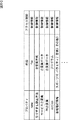
図20A乃至Cは、PMDの詳細な構成例を示す図である。同図に示されるPMDは、上述したように、あるサービスID(例えば、サービスID1)に関連付けられたメタデータの集合であり、そのメタデータの識別情報であるプロパティと、そのプロパティの内容が記述されている。プロパティ「name」は、サービスID1に対応するサービスシステム24に対して提供されたユーザIDを示すものであり、その内容は「foo」と記述されている。
20A to 20C are diagrams illustrating a detailed configuration example of PMD. As described above, the PMD shown in the figure is a set of metadata associated with a certain service ID (for example, service ID 1), and describes the property that is identification information of the metadata and the contents of the property. Has been. The property “name” indicates the user ID provided to the
図20Aにおいて、プロパティ「なりすまし防止方法」は、サービスID1に対応するサービスシステム24との間で行われるなりすまし防止の処理の方法を示すものであり、その内容は、「公開鍵方式」と記述されおり、図5のステップS82で生成される確認コードに対応する。プロパティ「サービス公開鍵」は、サービスID1に対応するサービスシステム24の公開鍵を示すものであり、その内容として鍵のデータが記述されている。プロパティ「PK秘密鍵」は、PK22の秘密鍵を示すものであり、その内容として鍵のデータが記述されている。
In FIG. 20A, the property “spoofing prevention method” indicates a method of anti-spoofing processing performed with the
なお、図20Bに示されるように、プロパティ「なりすまし防止方法」の内容が「共通鍵方式」と記述されている場合、プロパティ「サービス公開鍵」とプロパティ「PK秘密鍵」に代わってプロパティ「共通鍵」がPMDの中に生成され、その内容として鍵データが記述される。さらに、図20Cに示されるように、プロパティ「なりすまし防止方法」の内容が「合言葉方式」と記述されている場合、プロパティ「サービス公開鍵」とプロパティ「PK秘密鍵」に代わってプロパティ「サービス合言葉」とプロパティ「PK合言葉」がPMDの中に生成され、その内容としてそれぞれ、サービス合言葉とPK合言葉が記述される。 As shown in FIG. 20B, when the content of the property “spoofing prevention method” is described as “common key method”, the property “common” is used instead of the property “service public key” and the property “PK private key”. "Key" is generated in the PMD, and key data is described as its contents. Further, as shown in FIG. 20C, when the content of the property “spoofing prevention method” is described as “password method”, the property “service password” is substituted for the property “service public key” and the property “PK private key”. ”And the property“ PK secret ”are generated in the PMD, and the service secret and the PK secret are respectively described as the contents.
プロパティ「action」は、サービスID1に対応するサービスで実行される処理プログラムを示すものであり、その内容としてプログラムが記述されている。プロパティ「番組嗜好情報」は、サービスID1に対応するサービスで利用されるユーザの嗜好情報を示すものであり、その内容として、「スポーツ10、バラエティ7、音楽5、その他3」が記述されている。
The property “action” indicates a processing program executed by the service corresponding to the service ID 1, and the program is described as the content of the processing program. The property “program preference information” indicates user preference information used in the service corresponding to the service ID 1, and “
アクセス制御は、そのプロパティの内容に対するアクセス制御情報を記述したものであり、各プロパティに対して、制御情報が設定される。制御情報は、所定のビット数で構成されるコードであり、例えば、次のように設定される。 The access control describes access control information for the contents of the property, and control information is set for each property. The control information is a code composed of a predetermined number of bits, and is set as follows, for example.
第1番目のビットにより、サービスID1に対応するサービスにおける当該プロパティの内容の読み出し可否が設定される。第2番目のビットにより、サービスID1に対応するサービスにおける当該プロパティの内容の変更可否が設定される。第3番目のビットにより、サービスID1以外のサービスIDに対応するサービスにおける当該プロパティの内容の読み出し可否が設定され、第4番目のビットにより、サービスID1以外のサービスIDに対応するサービスにおける当該プロパティの内容の変更可否が設定される。 The first bit sets whether or not the content of the property in the service corresponding to the service ID 1 can be read. The second bit sets whether or not the content of the property in the service corresponding to the service ID 1 can be changed. The third bit sets whether or not the content of the property in the service corresponding to the service ID other than the service ID 1 can be read. The fourth bit sets the property in the service corresponding to the service ID other than the service ID 1. Whether the contents can be changed is set.
このほか、プログラムの実行可否を設定するビット、自由にアクセスすることが可能である(アクセス制限を設けない)ように設定するビットなどが設けられるようにしてもよい。なお、アクセス制御に設定される制御情報は、アクセス許可情報(図4)としてまとめて記憶されるようにしてもよい。 In addition, a bit for setting whether to execute the program, a bit for setting free access (no access restriction), or the like may be provided. Note that the control information set for access control may be collectively stored as access permission information (FIG. 4).
次に、図21を参照して、PMD更新処理について説明する。この処理は、例えば、サービスシステム24により、コンテンツの視聴サービスが提供された場合、図6のステップS207または図7のステップS411のサービス対応処理の1つとして、この処理がサービスシステム24により実行される。
Next, the PMD update process will be described with reference to FIG. For example, when the content viewing service is provided by the
ステップS1901において、CPU121は、視聴された番組(コンテンツ)のメタデータを取得する。ステップS1902において、CPU121は、メタデータのジャンルを分析する。ステップS1903において、CPU121は、ステップS1902で分析されたジャンルがスポーツであるか否かを判定し、ジャンルがスポーツであると判定された場合、ステップS1904に進み、PMDの中のプロパティ「番組嗜好情報」の内容におけるスポーツのポイントをアップさせる。例えば、図20において、「スポーツ10、バラエティ7、音楽5、その他3」とされていたものが、「スポーツ11、バラエティ7、音楽5、その他3」とされる。
In step S1901, the
ステップS1903において、ステップS1902で分析されたジャンルがスポーツではないと判定された場合、CPU121は、ステップS1905において、ジャンルがバラエティであるか否かを判定し、ジャンルがバラエティであると判定された場合、ステップS1906に進み、PMDの中のプロパティ「番組嗜好情報」の内容におけるバラエティのポイントをアップさせる。例えば、図20において、「スポーツ10、バラエティ7、音楽5、その他3」とされていたものが、「スポーツ10、バラエティ8、音楽5、その他3」とされる。
If it is determined in step S1903 that the genre analyzed in step S1902 is not a sport, the
ステップS1905において、ステップS1902で分析されたジャンルがバラエティではないと判定された場合、CPU121は、ステップS1907において、ジャンルが音楽であるか否かを判定し、ジャンルが音楽であると判定された場合、ステップS1908に進み、PMDの中のプロパティ「番組嗜好情報」の内容における音楽のポイントをアップさせる。例えば、図20において、「スポーツ10、バラエティ7、音楽5、その他3」とされていたものが、「スポーツ10、バラエティ7、音楽6、その他3」とされる。
If it is determined in step S1905 that the genre analyzed in step S1902 is not variety, the
ステップS1907において、ステップS1902で分析されたジャンルが音楽ではないと判定された場合、CPU121は、ステップS1909に進み、PMDの中のプロパティ「番組嗜好情報」の内容におけるその他のポイントをアップさせる。例えば、図20において、「スポーツ10、バラエティ7、音楽5、その他3」とされていたものが、「スポーツ10、バラエティ7、音楽5、その他4」とされる。
If it is determined in step S1907 that the genre analyzed in step S1902 is not music, the
このようにして、サービスシステム24においてPMDが更新される。更新されたPMDは、PK22に送信され、PK22のPMDが更新される。
In this way, the PMD is updated in the
以上においては、サービスシステム24により、PMD更新処理が実行され、その更新に対応してPK22のPMDが更新される例について説明したが、PK22においてPMD更新処理が実行されるようにしてもよい。あるいはまた、pBase23において、PMD更新処理が実行され、PK22のPMDがpBase23のPMDと同期されるようにしてもよい。
In the above, the PMD update process is executed by the
また、異なるサービスにおいて利用されるPMDの内容を組み合わせて新たにPMDを生成することも可能である。例えば、サービスID1に対応するサービスと、サービスID2に対応するサービスが、ともに音楽に関するコンテンツを提供するサービスであり、図22にしめされるようにサービスID1に対応するPMD301とサービスID2に対応するPMD302の中に、プロパティ「R&B」、プロパティ「jazz」、およびプロパティ「POP」が存在しているものとする。
It is also possible to newly generate PMD by combining the contents of PMD used in different services. For example, a service corresponding to service ID 1 and a service corresponding to service
この場合、PMD301とPMD302が組み合わせられ、新しいPMD303が生成される。このとき、PMD301のプロパティ「R&B」の内容(15)と、PMD302のプロパティ「R&B」の内容(17)が足し合わされ、新しいPMD303のプロパティ「R&B」の内容が、「32(=17+15)」に設定される。同様に、新しいPMD303のプロパティ「jazz」の内容は、「10(=5+5)」に設定され、新しいPMD303のプロパティ「POP」の内容が「15=(15+0)」に設定される。
In this case,
このようにして、生成された新しいPMD303は、例えば、複数の音楽提供サービスのサービスIDに対応するPMDとして生成され、PK22のユーザの音楽に関する嗜好情報として利用される。
Thus, the generated
また、サービスシステム24(または、pBase23)が、複数のPK22のPMDの内容を組み合わせて新たにPMDを生成することも可能である。図23に、この場合の例を示す。1つのサービスシステム24(または、pBase23)を利用するPKとして、PK22−1とPK22−2が存在し、PK22−1のPMD321と、PK22−2のPMD322の中に、プロパティ「R&B」、プロパティ「jazz」、およびプロパティ「POP」が存在している。このとき、サービスシステム24(または、pBase23)は、PMD321とPMD322を組み合わせて、新しいPMD323を生成する。
Further, the service system 24 (or pBase 23) can also generate a new PMD by combining the contents of PMDs of a plurality of
このとき、PMD321のプロパティ「R&B」の内容(15)と、PMD322のプロパティ「R&B」の内容(17)が足し合わされ、新しいPMD323のプロパティ「R&B」の内容が、「32(=17+15)」に設定される。同様に、新しいPMD323のプロパティ「jazz」の内容は、「10(=5+5)」に設定され、新しいPMD323のプロパティ「POP」の内容が「15=(15+0)」に設定される。
At this time, the content (15) of the property “R & B” of the
このようにして、生成された新しいPMD323は、例えば、複数のユーザの共通するPMDとして生成され、まだ嗜好情報が蓄積されていないPK22のユーザに対して、そのユーザの嗜好情報として提供される。
Thus, the generated
また、PK22に代えて別の機器から、サービスシステム24を利用することも可能である。このような場合、図24に示されるように、ユーザ20は、PK22を、ユーザ20が指定する端末362と通信させ、コンテンツアクセスパッケージ361を、端末362に送信される。そして、端末362がサービスシステム24と通信を行う。コンテンツアクセスパッケージ361は、サービスシステム24との通信を行うために必要な情報をまとめたパッケージであり、例えば、コンテンツのURI等のコンテンツを特定するユニークなID、コンテンツに関連する簡易な映像または文字列などにより構成されるアイコン、並びにサービスシステム24との間でおこなわれるなりすまし防止の処理に用いられるPK認証情報(例えば、PK22の秘密鍵、ユーザIDなど)、およびサービス認証情報(例
えば、サービスシステム24の公開鍵、サービスIDなど)により構成される。
It is also possible to use the
このようにすることで、ユーザは、端末362を、あたかもPK22であるかのように(仮想のPKとして)利用することができる。 In this way, the user can use the terminal 362 as if it were the PK22 (as a virtual PK).
次に、図25乃至図27を参照して、PMDを利用して、情報機器に自分の嗜好情報を反映させる(以下、パーソナライズと称する)例について説明する。図25において、PK22のユーザ20が、所定の音楽データに基づいて、音楽の再生を行う音楽再生機器381と、インターネット21に接続され、Webの閲覧などを行うパーソナルコンピュータ382を利用する。
Next, with reference to FIG. 25 to FIG. 27, an example in which the preference information is reflected on the information device using PMD (hereinafter referred to as personalization) will be described. In FIG. 25, a
ユーザ20は、PK22のPMDを利用して、音楽再生装置に、自分の好みの音楽を再生させることができる。この場合、PK22は、音楽再生装置381を1つのサービスシステムとして、インターネット21を介さずに無線通信などにより、音楽再生装置381と通信する。このとき、図6または図7に示されるような処理が、PK22と音楽再生装置381の間で行われる。このとき、例えば、図7のステップS409において、音楽再生装置381から音楽の嗜好情報のPMDの読み出し要求が、PK22に対して送信され、ステップS504で、PK22から音楽の嗜好情報のPMDが音楽再生装置381に対して送信される。そして、ステップS410で、音楽再生装置381が、PK22からPMDを取得すると、ステップS411のサービス対応処理として、ユーザの好みの音楽を再生する処理を実行する。この場合の音楽再生装置381の音楽再生処理について、図26を参照して説明する。
The
ステップS1921において、音楽再生装置381は、PK22からPMDを取得する。ステップS1922において、音楽再生装置381は、ステップS1921で取得されたPMDの中の嗜好情報を分析する。ステップS1923において、音楽再生装置381は、嗜好情報に対応する音楽を再生する。
In step S1921, the
このように、嗜好情報が含まれるPMDを、音楽再生装置381に送信することで、好みの音楽を再生することができる。PMDは、PK22に記憶されており、いろいろな場所に持ち運ぶことができるので、その場にある音楽再生装置を自分の好みの音楽を再生する音楽再生装置にパーソナライズすることが可能となる。
In this way, by transmitting the PMD including the preference information to the
また、図25において、ユーザ20は、pBase23のPMDを利用して、パーソナルコンピュータ382に、自分の好みのWebページを表示させることができる。この場合、PK22は、サービスシステム24−10と、インターネット21を介して通信する。このとき、図6または図7に示されるような処理が、PK22とサービスシステム24−10の間で行われる。そして、サービスシステム24−10は、PK22のユーザIDに基づいて、ユーザ20のPMDが記憶されているpBase23を特定し、pBase23からユーザ20のPMDを取得する。このとき、図18または図19に示されるような処理が、サービスシステム24―10とpBase23の間で行われ、例えば、図19のステップS1869において、サービスシステム24−10からWebの嗜好情報のPMDの読み出し要求が、pBase23に対して送信され、ステップS1891で、pBase23からWebの嗜好情報のPMDがサービスシステム24−10に対して送信される。
In FIG. 25, the
ステップS1870で、サービスシステム24−10が、pBase23からPMDを取得すると、ステップS1871のサービス対応処理として、パーソナルコンピュータ382に対して、ユーザの好みに合ったWebサービスを提供する処理を実行する。この場合のサービスシステム24−10のWeb情報提供処理ついて、図27を参照して説明する。
In step S1870, when the service system 24-10 acquires the PMD from the pBase23, as the service corresponding process in step S1871, a process of providing a Web service that suits the user's preference to the
ステップS1941において、サービスシステム24−10は、PK22のユーザIDを取得する。ステップS1942において、サービスシステム24−10は、ステップS1941で取得されたユーザIDに対応するPMDをpBase23から取得する。ステップS1943において、サービスシステム24−10は、ステップS1942で取得されたPMDの嗜好情報を分析する。ステップS1944において、サービスシステム24−10は、嗜好情報に対応するWebサービスを提供する。 In step S1941, the service system 24-10 acquires the user ID of the PK22. In step S1942, the service system 24-10 acquires the PMD corresponding to the user ID acquired in step S1941 from the pBase23. In step S1943, the service system 24-10 analyzes the preference information of PMD acquired in step S1942. In step S1944, the service system 24-10 provides a Web service corresponding to the preference information.
あるいはまた、サービスシステム24−10がユーザのパーソナルコンピュータ382に作成するテキストファイルであるクッキーが、PMDとしてPK22またはpBase23に保存され、Webの閲覧を行う都度、パーソナルコンピュータ382にクッキーが送信されるようにしてもよい。
Alternatively, a cookie, which is a text file created by the service system 24-10 on the user's
このようにして、Webサービスが提供される。例えば、容量が大きいためPK22に記憶することができないPMDをpBase23に記憶しておき、pBse23のPMDに基づいて、パーソナルコンピュータなどの情報機器をパーソナライズすることができる。その結果、ユーザの嗜好をより適確に反映したパーソナライズを行うことができる。
In this way, a web service is provided. For example, a PMD that cannot be stored in the
次に、図28を参照して、PMDを利用して、情報機器をパーソナライズする別の例について説明する。同図において、家400には、ユーザ20−1乃至20−3の3人のユーザが住んでおり、それぞれPK22−1乃至22−3を所有している。家400には、リビング400−1、キッチン400−2、および子供部屋400−3の3つの部屋があり、それぞれの部屋には、各種の映像または音楽などのデータ(コンテンツ)を取得し、コンテンツを記憶または再生するコンテンツボックス421−1乃至421−3が設置されている。
Next, another example of personalizing an information device using PMD will be described with reference to FIG. In the figure, in the
コンテンツボックス421−1乃至421−3は、LAN402を介してルータ403と接続されており、ルータ403を介してインターネット21に接続された各種のサーバと通信を行い、各種のコンテンツを取得する。
The content boxes 421-1 to 421-3 are connected to the
また、コンテンツボックス421−1乃至421−3は、歩紋を検知するセンサが設けられており、ユーザがその近傍を通過すると歩紋検知してユーザを特定する。ルータ403は、インターネット21からの不正なアクセスを防御するファイヤーウォール機能と、所定の容量のデータを記憶する記憶部を有している。LAN402には、PKを載置して充電を行うクレドール401が接続されており、クレドール401は、載置されたPKの情報をルータ403に送信する。
In addition, the content boxes 421-1 to 421-3 are provided with sensors for detecting a footprint, and when the user passes the vicinity, the footprint is detected to identify the user. The
ユーザ20−1乃至20−3は、外出時はPK22−1乃至22−3を携帯し、家400に帰宅するとクレドール401に自分が所有するPKを載置する。クレドール401は、PK22−1乃至22−3が載置されると、PK22−1乃至22−3のPMDをルータ403に送信し、ルータ403は、インターネット21を介してpBase23と通信し、pBase23からユーザ20−1乃至20−3のPMDを取得し、記憶部に記憶する。なお、ユーザ20−1乃至20−3のPMDには、ユーザ20−1乃至20−3の嗜好情報および歩紋情報が記憶されているものとする。
The users 20-1 to 20-3 carry PKs 22-1 to 22-3 when they go out and place their own PKs on the
コンテンツボックス421−1乃至421−3は、ルータ403からユーザ20−1乃至20−3の歩紋情報を取得し、近傍のユーザの好みにあったコンテンツの再生をおこなう。例えば、ユーザ20−2がキッチンにいるとき、ユーザ20−2の歩紋202−2を検知したコンテンツボックス421−2は、ルータ403からユーザ20−2のPMDを取得し、嗜好情報を分析し、自身が蓄積したコンテンツの中から嗜好情報に対応した音楽などを再生する。
The content boxes 421-1 to 421-3 obtain the gait information of the users 20-1 to 20-3 from the
また、ユーザ20−1と20−3がリビング400−1にいるとき、コンテンツボックス421−1は、ユーザ20−1と20−3の歩紋202−1と202−3を検知して、ルータ403から、ユーザ20−1のPMDと、ユーザ20−3のPMDを取得し、それぞれの嗜好情報を分析し、自身が蓄積したコンテンツの中から、例えば、ユーザ20−1の好みにあった音楽を再生し、ユーザ20−3の好みにあった映像を再生する。このように、家400の中のコンテンツボックス421−1乃至421−3を、近傍のユーザに対応してパーソナライズすることができる。
Further, when the users 20-1 and 20-3 are in the living room 400-1, the content box 421-1 detects the steps 202-1 and 202-3 of the users 20-1 and 20-3, and the router 202-1 From 403, the PMD of the user 20-1 and the PMD of the user 20-3 are acquired, the respective preference information is analyzed, and, for example, music that matches the preference of the user 20-1 from the contents accumulated by itself. And the video that suits the preference of the user 20-3 is reproduced. In this way, the content boxes 421-1 to 421-3 in the
この例では、コンテンツボックス421−1乃至421−3をパーソナライズする例について説明したが、同様の方法で、各種のCE機器などをパーソナライズすることも可能であり、ユーザはPKを用いて所望の機器をパーソナライズすることができる。 In this example, the example in which the content boxes 421-1 to 421-3 are personalized has been described. However, it is possible to personalize various CE devices by the same method, and the user can use the PK to select a desired device. Can be personalized.
ところで、上述したようにルータ403は、ファイヤーウォール機能を有しているので、例えば、LAN402に接続される機器とインターネット21に接続される機器との通信が制約されている(例えば、コンテンツボックスとpBaseの通信に利用できるプロトコル(ポート番号)が限られる)。このため、LAN402に接続される機器とインターネット21との通信は、図29に示されるようにして行われる。最初に、コンテンツボックス421−1からpBase23に対して、矢印441に示されるようにhttps(SSL)プロトコルを使って、セッションを開始する。セッションが確立された後、コンテンツボックス421−1とpBase23は、点線442に示されるようにhttpsプロトコルでの通信を行う。
Incidentally, since the
また、図17Aを参照して上述したように、PK22−1乃至22−3とpBase23の間では、PMDの同期が行われる。図28の例の場合、PMDの同期は、クレドール401およびコンテンツボックス421−1乃至421−3を介して行われる。PK22−1、クレドール401、pBase23、およびコンテンツボックス421−1の間でPMDの同期が行われる場合の処理の流れについて、図30を参照して説明する。
Further, as described above with reference to FIG. 17A, PMD synchronization is performed between the PKs 22-1 to 22-3 and the
ステップS2001において、PK22−1は、クレドール401に載置されると、自身のPMDの内容をクレドール401に送信し、ステップS2021においてこれが受信される。ステップS2022において、クレドール401は、ステップS2021で受信された情報をpBase23に送信し、ステップS2041でこれが受信される。ステップS2042において、pBase23は、図31を参照して後述するPMD同期処理を実行する。これにより、pBase23に記憶されているPMDが更新され、PK22−1のPMDを更新する同期データが生成される。
In step S2001, when the PK 22-1 is placed on the
ステップS2043において、pBase23は、同期データをクレドール401に送信し、ステップS2023で、これが受信される。ステップS2024において、クレドール401は、ステップS2023で受信された情報をPK22−1に送信し、ステップS2002で、これが受信される。そして、ステップS2003において、PK22−1は、ステップS2002で受信した同期データに基づいて、PK22−1のPMDを更新し、PK22−1のPMDとpBase23のPMDの同期が行われる。
In step S2043, the pBase23 transmits the synchronization data to the
コンテンツボックス421−1において、コンテンツが再生されると、ステップS2061において、コンテンツボックス421−1は、コンテンツの視聴履歴などの履歴情報をpBase23に送信し、ステップS2044で、これが受信され、pBase23は、履歴情報に基づいてPMDの嗜好情報を更新する。ステップS2045において、pBase23は、PMDの更新結果を同期データとして、クレドール401に送信し、ステップS2025でこれが受信される。ステップS2026において、クレドール401は、ステップS2025で受信された情報をPK22−1に送信し、ステップS2004で、これが受信され、ステップS2005において、PK22−1のPMDが更新される。
When the content is played back in the content box 421-1, in step S2061, the content box 421-1 transmits history information such as the viewing history of the content to the pBase23, which is received in step S2044, and the pBase23 is PMD preference information is updated based on the history information. In step S2045, the
このようにしてPMDの同期が行われる。 In this way, PMD synchronization is performed.
次に、図31を参照して、図30のステップS2042のPMD同期処理の詳細について説明する。 Next, details of the PMD synchronization processing in step S2042 of FIG. 30 will be described with reference to FIG.
ステップS2081において、CPU121は、図30のステップS2041で受信したPMDと、pBase23に記憶されているPMDの内容を比較する。このとき、pBase23に記憶されているPMDの中から、受信したPMDに対応するPMDが1つずつ抽出されて比較され、そのPMDが最後に更新された日時を表す更新日時の情報が比較される。
In step S2081, the
ステップS2082において、CPU121は、ステップS2041で受信したPMDの更新日時が、pBase23に記憶されているPMDの更新日時より新しいか否かを判定し、受信したPMDの更新日時が、pBase23に記憶されているPMDの更新日時より新しいと判定された場合、ステップS2083に進み、pBase23に記憶されているPMDの内容を受信したPMDの内容に更新する。
In step S2082, the
一方、ステップS2082において、CPU121は、ステップS2041で受信したPMDの更新日時が、pBase23に記憶されているPMDの更新日時より新しくないと判定された場合、ステップS2084に進み、pBase23に記憶されているPMDの内容を同期データとする。この同期データは、PMD同期処理の終了後、ステップS2043(図30)で、PK22−1に送信され、PK22−1において、同期データに基づくPMDの更新が行われる。
On the other hand, in step S2082, if the
ステップS2083またはS2084の処理の後、CPU121は、ステップS2085において、全てのPMDをチェックしたか否かを判定し、まだ全てのPMDをチェックしていないと判定された場合、ステップS2086に進み、次のPMDをチェックする。その後処理は、ステップS2081に戻り、それ以降の処理が繰り返し実行される。
After the process of step S2083 or S2084, the
ステップS2085において、全てのPMDをチェックしたと判定された場合、処理は終了される。 If it is determined in step S2085 that all PMDs have been checked, the process ends.
このようにして、pBase23において、PMDの同期が行われる。 In this way, PMD synchronization is performed in pBase23.
次に、PKに各種のカードの情報を保存して利用する例について図32を参照して説明する。この例では、カード情報を有するPMD461がPK22に保存されているものとする。例えば、ユーザ20が買い物をするとき、PK22は、レジ481と無線通信などにより通信を行い、PMD461の情報がレジ481に取得される。PMD461は、ユーザ20が保有するクレジットカードなどのカード1乃至カードNのカード番号が記述されたカード情報を含むPMDである。このとき、レジ481をサービスシステムとして、PK22とレジ481の間で図6または図7に示されるような処理が行われる。そして、レジ481は、買い物代金の決済などを行うカード処理サーバ483とインターネット21を介して通信し、代金を決済する。
Next, an example of storing and using information of various cards in the PK will be described with reference to FIG. In this example, it is assumed that
例えば、プリペイドカードの残高、カードの利用履歴などの情報は、インターネット21を介して接続される、別のサーバのデータベース482−1乃至482−Nに記憶されており、カード処理サーバ483は、代金の決済を行った後、データベース482−1乃至482−Nの内容を更新する。
For example, information such as the balance of the prepaid card and the card usage history is stored in databases 482-1 to 482-N of other servers connected via the
このようにすることで、PK22を仮想のカードケースとし、各種カードをカードケースにまとめて入れて、必要なときにそのカードを取り出して利用することができる。また、PK22にカードリーダ機能を設けて、カードの情報を読み込ませ、その内容がPK22の近傍のレジ481に送信されるようにしてもよい。
By doing in this way, PK22 can be used as a virtual card case, various cards can be put together in the card case, and the card can be taken out and used when necessary. Alternatively, the card reader function may be provided in the
次に、図33を参照して、PKを利用して、ユーザの周辺の機器の制御を行う例について説明する。同図において、ユーザ20は、PK22を携帯すると同時に、タッチパッド付ディスプレイ521を有するコンソール端末502を携帯し、プロジェクター503が設置された会議室に入る。会議室には、アクセスポイント25が設置されており、アクセスポイント25は、インターネット21に接続される。インターネット21には、プロジェクター503など、アクセスポイント25の周辺に存在する機器の制御情報を保有する環境サーバ501が接続されている。ユーザ20は、PK22を利用して、プロジェクター503の制御コードを取得し、コンソール端末502を操作して、プロジェクター503を制御する。
Next, with reference to FIG. 33, an example in which the peripheral devices of the user are controlled using the PK will be described. In the figure, a
このとき、環境サーバからプロジェクター503の制御コードを取得する処理の流れについて、図34を参照して説明する。ステップS2121において、PK22は、無線通信などによりコンソール端末502と通信を行い、コンソール端末502に対して機器情報の要求を送信し、ステップS2101においてこれが受信される。ステップS2102において、コンソール端末502は、自身の機器情報をPK22に送信し、ステップS2122でこれが取得される。
At this time, the flow of processing for acquiring the control code of the
また、ユーザが会議室に入るとPK22は、アクセスポイント25と無線通信などにより通信を行い、アクセスポイント25を経由して、環境サーバ501と通信を行う。このとき、環境サーバ501をサービスシステムとして図6または図7に示されるような処理が、PK22と環境サーバ501の間で行われる。そして、ステップS2123において、PK22は、コンソール端末502の機器情報を1つのPMDとして、環境サーバ501に対して、制御コードの取得要求を送信し、ステップS2141でこれが受信される。ステップS2142において、環境サーバ501は、コンソール端末502にインストールするプロジェクター503の制御コードを、PMDに追加してPK22に送信し、ステップS2124でこれが受信される。
When the user enters the conference room, the
その後、コンソール端末502をサービスシステムとして図6または図7に示されるような処理が、PK22とコンソール端末502の間で行われる。そして、ステップS2125において、PK22は、ステップS2124で受信したPMDをコンソール端末502に対して送信し、ステップS2103でこれが受信され、プロジェクター503の制御コードがコンソール端末502にインストールされる。ユーザ20は、タッチパッド付ディスプレイ521を操作して、プロジェクター503の制御を行う。
Thereafter, processing as shown in FIG. 6 or 7 is performed between the
このようにして、PKを利用して、ユーザの周辺の機器の制御が行われる。このように、周辺の機器に対応して、適切な制御コードやデータなどを選択して送信することで、各種の機器を適正に制御することができる。 In this way, the peripheral devices of the user are controlled using the PK. As described above, various devices can be appropriately controlled by selecting and transmitting appropriate control codes and data corresponding to peripheral devices.
また、PKを利用した、ユーザの周辺の機器の制御の別の例として、図35に示されるようなドアの開閉をおこなうこともできる。この例では、アクセスポイント25の周辺にドア543と、ドア543のロックなどを解除してドア543の開放処理を行うドア開放制御機542が存在する。ドア開放制御機542は、インターネット21を介して、ドア開放制御機542の制御コードを記憶しているサーバ541と接続されている。
Further, as another example of control of peripheral devices of the user using PK, the door can be opened and closed as shown in FIG. In this example, a
ユーザ20が、サービスポイント25と通信可能な範囲41の中に入ると、サーバ541をサービスシステムとして、図6または図7に示されるような処理が行われ、ユーザ20が携帯するPK22が、アクセスポイント25を介して、インターネット21に接続されているサーバ541と通信し、サーバ541は、ドア開放制御機542に対して、ドア543の開放処理を実行させるように制御する。
When the
この場合、例えば、ユーザ20(PK22)の近傍のドア543を特定するIDなどの情報が、PMDとして、サーバ541に送信され、サーバ541は、受信したPMDに基づいて、ドア543を特定し、ドア開放制御機542に対して、ドア543の開放処理を実行させる制御する制御コードを送信する。
In this case, for example, information such as an ID for identifying the
このように、ユーザ20がドア543の近くのアクセスポイント25の近傍に行くと、自動的にドア543が開放されるようにすることができる。また、PK22とサーバ541の間で、図6または図7に示されるようななりすまし防止の処理が行われるので、不正な侵入者などに対してドア543が開放されないようにすることができる。
Thus, when the
また、例えば、ドア543付近に守衛室などがあり、ドア543から不正な侵入者が入らないように守衛が監視している場合、例えば、図36に示されるように、PK22から、守衛室のパーソナルコンピュータ562に対して、ID番号と顔写真のデータが含まれるPMDを送信し、パーソナルコンピュータ562に、PMDに対応する顔写真が表示されるようにすることで、さらにセキュリティを強化することができる。このようにすることで、PK22(ユーザ20)のPMDに対応した顔写真が、パーソナルコンピュータ562に表示されるので、例えば、不正な侵入者が、盗んだPK22を使ってドア543から侵入しようとしても、顔写真と違う人物である(ユーザ20ではない)ことが守衛に分かってしまうため、ドア543から侵入することができない。
In addition, for example, when there is a guard room near the
次に、図37を参照して、PKを利用して、周辺の機器を使った会話を行う例について説明する。この例においては、ユーザ20−2が、PK22−1を所有するユーザ20−1との会話を希望しているものとする。そして、PK22−1は、pBase23と所定の時間間隔で通信を行い、図31を参照して上述したようにPMDの同期処理が行われているものとする。
Next, an example in which a conversation using peripheral devices is performed using PK will be described with reference to FIG. In this example, it is assumed that the user 20-2 desires a conversation with the user 20-1 who owns the PK 22-1. The PK 22-1 communicates with the
ユーザ20−1の周囲には、アクセスポイント25、電話機581、ならびにテレビ会議を行うとき利用するカメラ582とディスプレイ583が存在し、電話機581乃至ディスプレイ583の制御コードを記憶する環境サーバ584が、インターネット21に接続されている。さらに、インターネット21には、pBase23と、会話の接続サービスを提供する会話接続サーバ601が接続されている。会話接続サーバ601は、ユーザ(例えば、ユーザ20−2)から、特定の相手(例えば、ユーザ20−1)に対する会話接続要求を受け付けて、相手の周辺の機器を使った会話を提供する。
Around the user 20-1, there are an
この場合、会話接続を行う処理の流れについて、図38を参照して説明する。PK22−1は、電話機581乃至ディスプレイ583などの周辺機器をサービスシステムとし、図6または図7に示されるような処理を行い、周辺機器と通信する。そして、ステップS2221において、PK22−1は、周辺機器に対して機器情報の要求を送信し、ステップS2201で、これが受信される。ステップS2202において、電話機581乃至ディスプレイ583など周辺機器は、自身のIDまたはアドレスなどの機器情報をPK22−1にPMDとして送信し、ステップS2222で、これが受信される。受信されたPMDは、ステップS2223において、ユーザ20−1が利用可能な機器を表すPMDとしてpBase23に送信され、ステップS2241でこれが受信される(PK22−1とpBase23で、PMDの同期が行われる)。
In this case, the flow of processing for performing conversation connection will be described with reference to FIG. The PK 22-1 uses peripheral devices such as the
一方、ユーザ20−2から、ユーザ20−1に対する会話の接続要求を受け付けた会話接続サーバ601は、ステップS2261において、ユーザ20−1に対応するPMDを保持するpBase23に対して、会話要求を送信し、ステップS2242で、これが受信される。このとき、会話接続サーバ601をサービスシステムとし、pBase23が、PK22−1の代わりとなって(代行して)、会話接続サーバ601とpBase23の間で、図6または図7に示されるような処理を行い通信が行われる。そして、pBase23は、ステップS2243において、ユーザ20−1が利用可能な機器を表すPMDを会話接続サーバ601に対して送信する。
On the other hand, the
ステップS2263において、会話接続サーバ601は、環境サーバ584を介して、周辺機器を制御し、ユーザ20−1と20−2の間で、電話機581による会話、またはカメラ582とディスプレイ583によるテレビ会議が行われる。このように、PKを利用して、周辺の機器を使った会話が行われる。このようにすることで、ユーザ20−1が、別の場所に行っても、ユーザ20−1が利用可能な機器を表すPMDに基づいて、会話を行うことができる。また、PK22−1とpBase23の間で、所定の時間間隔(例えば、30分間毎)にPMDの同期が行われるので、ユーザは、いつでも、どこでも周辺機器を利用して会話を行うことができる。
In step S2263, the
次に、PKを利用してユーザの現在地を特定する例について、図39を参照して説明する。この例では、ユーザ20は、PK22を携帯しており、PK22は、近傍のアクセスポイント25−1と通信する。アクセスポイント25−1乃至25−nは、スペースサーバ641と接続されており、スペースサーバ641は、PK22が通信しているアクセスポイントのIDなどの情報を記憶する。また、スペースサーバ641は、インターネット21と接続されており、インターネット21には、pBase23と、ユーザの現在地を特定するロケーションサーバ642が接続されている。
Next, an example of specifying the current location of the user using PK will be described with reference to FIG. In this example, the
この場合、インターネットに接続された機器643を用いて、ユーザの現在地を特定する処理の流れについて、図40を参照して説明する。
In this case, the flow of processing for specifying the current location of the user using the
PK22は、スペースサーバ641をサービスシステムとし、図6または図7に示されるような処理を行い、スペースサーバ641と通信する。そして、ステップS2321において、PK22は、スペースサーバ641に対して、今、PK22が通信しているアクセスポイントのIDの取得を要求し、ステップS2301において、これが受信される。ステップS2302において、スペースサーバ641は、アクセスポイント25−1のIDをPMDとして、PK22に送信し、ステップS2322で、これが受信される。受信されたPMDは、ステップS2323において、ユーザ20の近傍のアクセスポイントを表すPMDとしてpBase23に送信され、ステップS2341でこれが受信される(PK22とpBase23で、PMDの同期が行われる)。
The
一方、機器643は、ステップS2381において、ユーザ20の現在地の取得要求をロケーションサーバ642に対して送信し、ステップS2361で、これが受信される。ステップS2362において、ロケーションサーバ642は、ユーザ20のPMDを保持するpBase23に対して、ユーザ20の現在地の取得要求を送信し、ステップS2342で、これが受信される。このとき、ロケーションサーバ642をサービスシステムとし、pBase23が、PK22の代わりとなって(代行して)、ロケーションサーバ642とpBase23の間で、図18または図19に示されるような処理が行われ、通信が行われる。そして、ステップS2343において、pBase23は、ユーザ20の近傍のアクセスポイントを表すPMDをロケーションサーバ642に対して送信し、ステップS2363で、これが受信される。
On the other hand, the
ロケーションサーバ642は、ステップS2363で受信されたPMDに基づいて、ユーザ20の近傍のアクセスポイント(今の場合、アクセスポイント25−1)の情報を取得し、そのアクセスポイントの位置を特定する。そして、ロケーションサーバ642は、アクセスポイント25−1の近傍を、ユーザ20の現在地とし、その現在地の情報を、ステップS2364において、機器643に送信し、ステップS2382で、これが受信される。
Based on the PMD received in
このように、PKを利用して、ユーザ20の現在地が特定される。このようにすることで、ユーザ20が、別の場所(例えば、アクセスポイント25−2の近傍)に行っても、ユーザ20の近傍のアクセスポイントを表すPMDに基づいて、現在地を正確に特定することができる。
In this way, the current location of the
また、ユーザ20の近傍のアクセスポイントを表すPMDが、PK22に記憶されるようにしてもよい。例えば、図41に示されるように、ユーザ20が旅行などで移動するとき、PK22を携帯し、PK22は、ユーザの現在地(近傍のアクセスポイントの情報)と、行き先のアドレスを含むPMD660を生成する。ユーザ20は移動中に、地図情報を提供する端末661と、PK22を通信させ、PMD660を端末661に送信させる。これにより、例えば、端末661に、現在地から目的地までの道を案内する地図が表示される。
Also, a PMD representing an access point near the
また、PMD660を方向表示機662に送信させ、進むべき方向が表示されるようにしてもよい。このようにPMD660を利用することで、ユーザにとって利便性の高い、道案内をすることができる。
Also,
あるいはまた、このようにして特定されたユーザの現在地に基づいて、ユーザへのメッセージが伝達されるようにすることも可能である。例えば、インターネットに接続されたメールサーバが、スペースサーバ641からユーザの現在地の情報を取得し、図37に示されるような方法で、ユーザが利用可能な機器に関する情報を取得して電子メールを送信することもできる。このようにすることで、例えば、ユーザが本社にいるときは、本社のパーソナルコンピュータに電子メールが送信され、ユーザが、支社に出張しているときは、支社のパーソナルコンピュータに電子メールが送信される。その結果、ユーザは、どこにいても確実に自分宛のメッセージを受け取ることができる。
Alternatively, a message to the user can be transmitted based on the current location of the user specified in this way. For example, a mail server connected to the Internet obtains information on the current location of the user from the
以上においては、ユーザの近傍のアクセスポイントの情報からユーザの現在地を特定する例について説明したが、より詳細に現在地を特定することもできる。例えば、図42に示されるように、アクセスポイント25の近傍にPK22−1を携帯するユーザ20−1と、PK22−2を携帯するユーザ20−2がいる場合、PK22−1または22−2は、スペースサーバ641と通信し、ユーザ20−1または20−2の顔特徴情報を含むPMDをスペースサーバ641に送信する。なお、PK22−1または22−2は、範囲41の中において、アクセスポイント25と通信することができるものとする。
In the above description, the example in which the current location of the user is specified from the information on the access points in the vicinity of the user has been described. For example, as shown in FIG. 42, when there is a user 20-1 carrying a PK 22-1 and a user 20-2 carrying a PK 22-2 in the vicinity of the
カメラ681は、アクセスポイント25に近接して設置され、範囲42の中にあるオブジェクトを撮影し、画像データを出力する。スペースサーバ641は、カメラ681と接続されており、カメラ681から出力される画像データを、ユーザ20−1または20−2の顔特徴情報と比較する。そして、顔特徴情報が一致する画像が検出された場合、スペースサーバ641は、ユーザ20−1または20−2は、アクセスポイント25の近傍にいるものと判定し、アクセスポイント25のIDをPK22−1または22−2に送信する。
The
このようにすることで、ユーザ20−1または20−2の現在地を、アクセスポイントの近傍(範囲41の中)から、さらに詳細に、カメラ681の近傍(範囲42の中)として特定することができる。 By doing in this way, the present location of the user 20-1 or 20-2 can be specified from the vicinity of the access point (in the range 41) as the vicinity of the camera 681 (in the range 42) in more detail. it can.
あるいはまた、カメラ681から出力される画像データが、PMDとしてpBase23に記憶され、ユーザの現在地の周辺の情報として、必要に応じてサービスシステムに提供されるようにしてもよい。このようにすることで、ユーザの正確な現在地を隠蔽しつつ、ユーザの周辺の映像を提供することができる。
Alternatively, the image data output from the
ところで、複数のアクセスポイントが、比較的近傍に設置されている場合、PK22は、通信すべきアクセスポイントを選択(検出)する必要がある。
By the way, when a plurality of access points are installed relatively close, the
図43を参照して、PK22によるアクセスポイントの検出の例であるアクセスポイント検出処理1について説明する。ステップS2501において、PK22は、通信出力のパワーを最小にする。上述したように、PK22は、RF(Radio Frequency)通信、準静電界通信、光通信などの無線通信によりアクセスポイントと通信を行う。ステップS2501においては、例えば、PK22の電波出力を最小に設定する。
With reference to FIG. 43, the access point detection process 1 which is an example of the detection of the access point by PK22 is demonstrated. In step S2501, the
ステップS2502において、PK22は、アクセスポイントが検出されたか否かを判定し、アクセスポイントが検出されなかったと判定された場合、ステップS2504に進み、通信出力のパワーが最大か否かを判定し、まだ最大ではないと判定された場合、ステップS2505に進み、通信出力のパワーを1段階上げる。そして、処理は、ステップS2502に戻り、それ以降の処理が繰り返し実行される。
In step S2502, the
図44を参照して、さらに詳しく説明する。PK22は、通信パワーが最小出力の場合、範囲701に電波を出力することができる。アクセスポイント25−1乃至25−nは、PK22からの電波を検知すると、応答を発信し、PK22において、これが受信されることにより、PK22がアクセスポイントを検出する。範囲701には、アクセスポイントがないため、PK22は、アクセスポイントを検出できない。そこで、PK22は、通信出力のパワーを1段階上げて、範囲702に電波を出力する。範囲702の中には、アクセスポイント25−1が存在し、PK22は、アクセスポイント25−1を検出する。
This will be described in more detail with reference to FIG. The
図43に戻って、ステップS2502において、アクセスポイントが検出されたと判定された場合、PK22は、ステップS2503に進み、検出されたアクセスポイント25−1と通信する。
Returning to FIG. 43, if it is determined in step S2502 that an access point has been detected, the
一方、ステップS2504において、通信出力のパワーが最大であると判定された場合、PK22の近傍にアクセスポイントはないものと判定され、ステップ2506において、エラー処理が実行され、アクセスポイント検出処理は終了される。 On the other hand, if it is determined in step S2504 that the power of the communication output is maximum, it is determined that there is no access point in the vicinity of PK22. In step 2506 , error processing is executed, and the access point detection processing is terminated. The
このように、PK22は、その通信出力を序所に上げていき、最初に見つかったアクセスポイントと通信する。このようにすることで、例えば、図44において、PK22は、アクセスポイント25−2と通信しないようにできるので、通信による消費電力を抑制することができる。
In this way, the
図43においては、PK22が、通信出力を変化させ、アクセスポイントを検出する例について説明したが、PKの通信出力が同じでも、複数のアクセスポイントが検出される場合もある。そのような場合、アクセスポイントから発せられる通信出力(例えば、電界強度)に基づいて、アクセスポイントが検出されるようにしてもよい。図45を参照して、PK22によるアクセスポイントの検出の別の例であるアクセスポイント検出処理2について説明する。
In FIG. 43, an example in which the
ステップS2521において、PK22は、検出されたアクセスポイントの電界強度を取得する。ステップS2522において、PK22は、電界強度が最も大きいアクセスポイントを検索する。ステップS2523において、PK22は検索されたアクセスポイントと通信する。
In step S2521, the
図46を参照して、さらに詳しく説明する。範囲711−1において、アクセスポイント25−1から出力される電波は電界強度1で、PK22に受信される。範囲712−1において、アクセスポイント25−1から出力される電波は電界強度2で、PK22に受信される。同様に、範囲711−2において、アクセスポイント25−2から出力される電波は電界強度1で、PK22に受信され、範囲712−2において、アクセスポイント25−2から出力される電波は電界強度2で、PK22に受信される。
This will be described in more detail with reference to FIG. In the range 711-1, the radio wave output from the access point 25-1 is received by the
いま、PK22は、アクセスポイント25−1から出力される電波を電界強度1で受信しており、同時に、アクセスポイント25−2から出力される電波を電界強度2で受信している。このような場合、複数のアクセスポイント(アクセスポイント25−1と25−2)の中から、電界強度が最も大きいアクセスポイントが検索される。いまの場合、アクセスポイント25−1が検索され、PK22は、アクセスポイント25−1と通信する。
Now, the
このようにして、アクセスポイントが検出される。このようにすることで、例えば、ユーザがいる部屋とその部屋に隣接する部屋の両方にアクセスポイントが設置されている場合であっても、PK22は、確実に、ユーザがいる部屋のアクセスポイントを利用した通信を行うことができる。
In this way, the access point is detected. In this way, for example, even when access points are installed in both the room where the user is located and the room adjacent to the room, the
なお、PKの通信経路は1つに限られるものではなく、複数あってもよい。また、複数の通信経路において、それぞれ異なる方法で通信が行われるようにしてもよい。図47は、PK22の複数の通信経路を示す図である。 Note that the communication path of the PK is not limited to one, and there may be a plurality of communication paths. Further, communication may be performed by a different method in each of a plurality of communication paths. FIG. 47 is a diagram showing a plurality of communication paths of the PK22.
同図において、PK22は、範囲41に電波を出力し、アクセスポイント25とRF通信を行う。そして、アクセスポイント25を経由して、インターネット21に接続され、サービスシステム24−2と通信が行われる。一方、PK22は、光通信用のインタフェース762を有する近傍のパーソナルコンピュータ761と光通信を行う。この場合、例えば、赤外線のような指向性のある光が、矢印781に沿ってPK22とパーソナルコンピュータ761から照射される。
In the figure, the
また、ユーザ20が、準静電界通信用のインタフェース763の上にいるとき、PK22は、矢印782に示されるように、インタフェース763と準静電界通信を行う。インタフェース763は、サービスシステム24−1と接続されており、PK22は、インタフェース763を経由して、サービスシステム24−1と通信を行う。
The
例えば、図39に示されるように、ユーザの現在地を特定する場合、ユーザ(PK22)の現在地が、RF通信のアクセスポイント25の位置情報ではなく、準静電界通信用のインタフェース763の位置情報に基づいて、特定されるようにすれば、ユーザの現在地をより詳細に特定することができる。また、指向性の高い光通信用のインタフェース763の位置情報に基づいて、ユーザの現在地が特定されるようにすれば、さらに正確にユーザの現在地を特定することができる。例えば、会議室の机に、光通信用のインタフェース763を複数設けておき、着座したユーザが、それぞれが所持するPKを光通信用のインタフェース763と光通信させるようにすれば、どの席にどのユーザが着座したのかを正確に把握することができる。
For example, as shown in FIG. 39, when specifying the current location of the user, the current location of the user (PK22) is not the location information of the
あるいはまた、図5に示されるようなサービスシステム24の初期登録を行う場合の通信と、その後の通信で、異なる通信経路が設定されるようにしてもよい。例えば、サービスシステム24の初期登録を行う場合、PK22とサービスシステム24の間で、まだなりすまし防止方法が定められていないので、PK22が光通信などの通信が傍受され難い通信により、サービスシステム24と直接通信して初期登録を行い、その後の通信は、RF通信により、インターネット21を介してサービスシステム24と通信するようにしてもよい。このようにすることで、より安全なサービスを提供することができる。
Alternatively, different communication paths may be set for communication in the initial registration of the
上述したようにPKは小型のコンピュータであり、PK自身にプログラムを実行させ、所定の処理(例えば、受信した電子メールを表示させる処理)を行うようにすることも可能である。図48と図49を参照して、PKにプログラムを実行させ、所定の処理を行う例について説明する。 As described above, the PK is a small computer, and it is possible to cause the PK itself to execute a program and perform a predetermined process (for example, a process for displaying a received electronic mail). With reference to FIGS. 48 and 49, an example in which a program is executed by the PK and a predetermined process is performed will be described.
図48において、PKがPMD801を有しているものとする。PMD801のプロパティ「プログラム」は、PK22が実行するプログラムを表すものであり、その内容として、プログラムコードの実体が記憶されている。プロパティ「name」は、PKのユーザIDを表すものであり、その内容は、「foo」とされている。プロパティ「push」は、処理すべきデータ(例えば受信した電子メール)を表すものであり、その内容として、「緊急の連絡あり・・・」が記述されている。
In FIG. 48, it is assumed that PK has PMD801. The property “program” of the
次に、図49を参照して、PK22がプログラムを実行する処理について説明する。この処理は、所定の周期(例えば、1時間毎)に行われるようにしてもよいし、ユーザの指令に基づいて、実行されるようにしてもよい。ユーザの指令は、例えば、PK22の入力部106を構成するスイッチが、所定の回数押下されることにより行われる。ステップS2541において、CPU101は、PMD801のプロパティ「push」にデータがあるか否かを判定し、データがあると判定された場合、ステップS2542に進み、プロパティ「push」の内容をディスプレイに表示させる。いまの場合、「緊急の連絡あり・・・」が表示される。ステップS2543において、CPU101は、プロパティ「push」の内容を消去する。
Next, with reference to FIG. 49, a process in which the
ステップS2541において、データがないと判定された場合、処理は終了される。 If it is determined in step S2541 that there is no data, the process ends.
このようにして、PK自身にプログラムを実行させ、例えば、受信した電子メールを表示させる処理が実行される。例えば、PKを1つのサービスシステムとして、別のPKとの間で、図6または図7に示されるような処理が行われ、電子メールの送受信を行うようにすれば、なりすまし防止処理により、ユーザを正確に認証することができるので、電子メールのセキュリティをより向上させることができる。 In this way, a process for causing the PK itself to execute the program and displaying the received e-mail, for example, is executed. For example, if the PK is used as one service system and the process shown in FIG. 6 or FIG. 7 is performed with another PK, and an e-mail is transmitted / received, the spoofing prevention process allows the user to perform the process. Can be accurately authenticated, so that the security of e-mail can be further improved.
また、pBase23を1つのサービスシステムとして、PK22と通信させ、pBase23からの要求に基づいて、PK22がプログラムを実行することも可能である。この場合の処理の流れについて、図50を参照して説明する。同図は、図7に対応しており、図7のサービスシステム24に代わってpBase23とされている。
It is also possible for the
図50のステップS2801乃至S2808の処理は、図7のステップS401乃至S408の処理と同様の処理なので、その説明は省略する。図50のステップS2821乃至S2836の処理は、図7のステップS421乃至S436と同様の処理なので、その説明は省略する。図50のステップS2881乃至S2891は、図7のステップS481乃至S491と同様であり、図50のステップS2901とS2902は、図7のステップS501とS502と同様なのでその説明は省略する。 The processes in steps S2801 to S2808 in FIG. 50 are the same as the processes in steps S401 to S408 in FIG. The processes in steps S2821 to S2836 in FIG. 50 are the same as those in steps S421 to S436 in FIG. Steps S2881 to S2891 in FIG. 50 are the same as steps S481 to S491 in FIG. 7, and steps S2901 and S2902 in FIG. 50 are the same as steps S501 and S502 in FIG.
ステップS2809において、pBase23は、PK22に対して、プログラムの実行要求を送信し、ステップS2835において、PK22の通信モジュール61によりこれが受信される。ステップS2836において、通信モジュール61は、ステップS2835で受信された内容を、DBアクセスモジュール66を経由してプログラムに対して出力し、ステップS2921において、これが受信されプログラムが実行される。
In step S2809, the
このようにして、pBase23からの要求に基づいて、PK22のプログラムが実行される。 In this way, the program of PK22 is executed based on the request from pBase23.
なお、図50においては、pBase23を1つのサービスシステムとして、PK22と通信させる例について説明したが、PK22−1が、別のPKであるPK22−2を1つのサービスシステムとし、PK22−2と通信を行うことも可能である。 In FIG. 50, the example in which pBase23 is used as one service system and communicates with PK22 has been described. However, PK22-1 uses another PK2 as PK22-2 as one service system and communicates with PK22-2. It is also possible to perform.
ところで、PK22は、ユーザが携帯するものなので、バッテリーなどにより電力が供給される。このため、通信に用いられる電力は最小限にすることが望ましい。図51を参照して、PK22の通信スタンバイ処理について説明する。
By the way, since the
ステップS3101において、CPU101は、待ちうけモードで通信する。このとき、PK22においては、例えば、図47に示した複数の通信経路のうち、最も消費電力が少ない準静電界通信のみが行われる。ステップS3102において、CPU101は、通信があったか否かを判定し、通信があったと判定された場合、ステップS3103において、802.11bによるRF通信を起動する。ステップS3104において、CPU101は、所定の時間が経過したか否かを判定し、所定の時間が経過したと判定されるまで待機する。
In step S3101, the
ステップS3104において、所定の時間が経過したと判定された場合、CPU101は、ステップS3105に進み、802.11bによるRF通信を終了する。その後、処理は、ステップS3101に戻り、それ以降の処理が繰り返し実行される。
If it is determined in step S3104 that the predetermined time has elapsed, the
図52と図53を参照してさらに詳しく説明する。図52において、ユーザ20が、準静電界通信用のインタフェース821−1乃至821−3の上にいるとき、PK22は、インタフェース821−1乃至821−3と準静電界通信を行う。サービスシステム822は、インタフェース821−1乃至821−3と接続されており、常に、サービスIDとサービス情報により構成されるパケット823をインタフェース821−1乃至821−3に送信している。いま、ユーザ20が、インタフェース821−1の上にいるので、PK22は、パケット823を受信し、通信があったと判定する(図51のステップS3102)。
This will be described in more detail with reference to FIGS. In FIG. 52, when the
そして、PK22は、RF通信を起動し(図51のステップS3103)、図53に示されるように、範囲41の中にあるアクセスポイント25と通信を行い、アクセスポイント25を経由して、サービスシステム822との通信を行う。
Then, the
このようにすることで、通常(待ち受けモード時)は、RF通信と比較して消費電力の少ない準静電界通信を行い、サービスシステム822と通信する必要があるときだけ、準静電界通信と比較して通信速度が高いRF通信を用いて高速通信を行うようにすることができ、消費電力を抑制し、効率よく通信することができる。
In this way, normally (in standby mode), quasi-electrostatic field communication that consumes less power than RF communication is performed, and only when it is necessary to communicate with the
次に、PKまたはpBaseにより、実現されるサービスを複数組み合わせた例について、図54乃至図58を参照して説明する。図54Aにおいて、PK22を携帯したユーザが、アクセスポイントが設置された部屋にはいると、pBase23からユーザ20に対する連絡内容が送信される。これにより、例えば、PK22のディスプレイに「Aさんから連絡あり」のメッセージが表示される。あるいはまた、図54Bに示されるように、部屋881の中の床に設置された表示装置882が点灯することにより、ユーザ20に対してメッセージがあることが通知されるようにしてもよい。
Next, an example in which a plurality of services realized by PK or pBase are combined will be described with reference to FIGS. 54 to 58. In FIG. 54A, when the user carrying the
自分に対する連絡があることを知ったユーザ20は、PK22をパーソナルコンピュータ901と通信させ、図55に示されるように、パーソナルコンピュータ901に、pBase23からコミュニケーションリストを含むPMDを取得させ、コミュニケーションリストを表示させる。コミュニケーションリストは、ユーザ20に対して、連絡があった人の一覧を記述したリストであり、例えば、人物A乃至Dの4人からの連絡があったことが記述されている。
The
人物A乃至DもそれぞれPKを所持しており、図39に示されるような方法で、それぞれの現在地が特定され、コミュニケーションリストには、たとえば、人物Aは移動中であり、人物Bは自席におり、人物Cは会議室Cにおり、人物Dは伝言を残している旨が表示される。 Each of the persons A to D also has a PK, and the current location is specified by a method as shown in FIG. 39. For example, the person A is moving and the person B is at his seat in the communication list. The person C is in the conference room C, and the person D is left with a message.
例えば、会議室にいる人物Cと連絡をとりたいとき、ユーザ20は、近傍の会議室Aに入り、会議室Cとテレビ会議を行う。図56に示されるように、会議室Aには、電子ドキュメントなどを表示するモニタ921、相手の顔を表示するモニタ922、会議室Cの全体の様子を表示するモニタ923、およびタッチパッド付ディスプレイを備えたコンソール端末924が設置されている。
For example, when the
このとき、ユーザ20は、図33に示されるような方法で、コンソール端末924にモニタ921乃至923の制御コードをインストールし、コンソール端末924を操作して、モニタ921乃至923を制御する。
At this time, the
ここで、図57に示されるように、会議室Cに、人物C、および人物F乃至Iの6人がいる場合、各人物が、それぞれ自分のPKを所有しているものとし、各自のPKを会議室Cの机に設置された光通信装置と通信させる。光通信は、指向性が強いので、PKの存在する場所を正確に特定することができる。これにより、例えば、会議室Aのコンソール端末924に人物C、および人物F乃至Iの名前、所属、および着席位置などが表示される。
Here, as shown in FIG. 57, when there are six persons C and persons F to I in the conference room C, it is assumed that each person owns his / her own PK. To communicate with the optical communication device installed on the desk in the conference room C. Since optical communication has strong directivity, the location where the PK exists can be specified accurately. Thereby, for example, the names, affiliations, and seating positions of the person C and persons F to I are displayed on the
このように、PKとpBaseにより、ユーザにとって利便性の高いコミュニケーションの仕組を提供することができる。 Thus, the PK and pBase can provide a highly convenient communication mechanism for the user.
図58は、PK22とpBase23の組み合わせによるIP電話機961の待ちうけ電力を抑制する例を説明する図である。PK22を携帯したユーザ20の近傍に、アクセスポイント25と、IP電話機961があり、IP電話機961は、インターネット21に接続され、所定の相手と通話を行う。なお、消費電力抑制のために、IP電話機961は、通常電源がOFFの状態にされている。
FIG. 58 is a diagram for explaining an example of suppressing the power received by
この場合、PK22は、アクセスポイント25を介して、pBase23と通信を行い、図37に示されるような方法で、ユーザ20が利用可能な機器を表すPMDをpBase23に送信する(図58の矢印1001)。ユーザ20との会話を希望する機器981は、インターネット21の会話接続サーバに対して会話接続要求を行い、会話接続要求が、pBase23に送信される(図58の矢印1002)。pBase23は、PK22と通信し、会話接続要求を通知する(図58の矢印1003)。この結果、図49を参照して上述したように、PK22のディスプレイに接続要求が表示される。
In this case, the
ユーザ20が、会話接続要求があることを知り、IP電話機961の電源をONにすると、IP電話機961が利用可能となったことがpBase23に送信される(図58の矢印1004)。さらに、pBase23から機器981に対してIP電話機961が利用可能となったことが通知される(図58の矢印1005)これにより、機器981とIP電話機961による通話が開始される。
When the
このようにして、ユーザ20は、消費電力を抑制しながらIP電話機961を利用することができる。
In this way, the
以上においては、PK22を、ユーザが携帯可能な小型のコンピュータとして説明したが、図4のソフトウェア60を、例えば、汎用のパーソナルコンピュータなどに実装することにより、汎用のパーソナルコンピュータがPKとして利用されるようにすることも可能である。
In the above description, the
図59は、PK22のソフトウェア60を、ユーザが持ち歩く携帯機器1101と1102に実装する例を示す図である。同図において、携帯機器1101と1102は、ユーザが所望する音楽データを再生する、例えばウォークマン(商標)のような小型の音楽再生装置である。携帯機器1101と1102には、PK22のソフトウェア60が実装されているとともに、ユーザの嗜好情報に適合する音楽データの取得または送信を行うサービスシステムであるサービスシステム24−20のソフトウェアが実装されている。
FIG. 59 is a diagram illustrating an example in which the
すなわち、携帯機器1101と1102は、PK22とサービスシステム24−20を1つの情報処理装置として実現したものであり、ユーザは、通信によるデータの授受を行うことなく、サービスの提供を受けることができる。この結果、ユーザは、どこに行っても、携帯機器1101または1102に蓄積されたPMDの嗜好情報に基づいて、自分の好みに合う音楽を聴くことができる。
That is, the
また、携帯機器1101と1102に通信機能を設けるようにしてもよい。このようにすることで、例えば、携帯機器1101のユーザ22−11と、携帯機器1102のユーザ22−12が道で会ったとき、自分の好みに合う音楽の音楽データを交換し合うことができる。
In addition, the
なお、図25においては、ユーザのPMDの中の嗜好情報に基づいて、パーソナライズが行われる例について説明したが、例えば、ネットワークに接続される他のサーバにおいて、ユーザの嗜好が既に分析されている場合、その分析結果と合わせて、より詳細なパーソナライズを行うことも可能である。図60において、インターネット21に接続されるサービスシステム24−21は、PK22のユーザの嗜好情報に基づいて、テレビ番組を推薦する。一方、インターネット21には、協調フィルタリングによりユーザの嗜好を分析する協調フィルタリングサーバ1201が接続されている。
In FIG. 25, the example in which personalization is performed based on the preference information in the user's PMD has been described. However, for example, the user's preference is already analyzed in another server connected to the network. In this case, it is possible to perform more detailed personalization together with the analysis result. In FIG. 60, the service system 24-21 connected to the
協調フィルタリングサーバ1201は、pBase23からユーザのPMDを取得し、PMDに含まれる視聴(操作)履歴を分析する。そして、あるユーザの視聴履歴に対して、他のユーザの視聴履歴との間でマッチングを取り、当該ユーザと視聴履歴の類似する他のユーザの視聴履歴を取得する。そして、視聴履歴が類似する(好みが似ている)他のユーザが視聴した番組で、当該ユーザが未だ視聴していない番組名を取得し、推薦する。
The
このようにして協調フィルタリングサーバ1201により推薦される番組を、サービスシステム24−21が、PK22のPMDに基づいて、さらに選択し、ユーザに推薦する。このようにすることで、ユーザに対して、より嗜好に適合する番組を推薦することができる。
In this way, the service system 24-21 further selects a program recommended by the
勿論、協調フィルタリングサーバ1201により推薦される番組が直接ユーザに推薦されるようにしてもよい。上述したように、PK22またはpBase23により、ユーザのPMDの中に嗜好情報が既に蓄積されているので、PK22またはpBase23を用いずに、ユーザが使用する機器(例えば、テレビジョン受像機など)の視聴履歴などから直接嗜好情報を収集して、番組の推薦を行う場合と比較して、協調フィルタリングサーバ1201の処理負荷を軽減することができる。
Of course, the program recommended by the
なお、本明細書において上述した一連の処理を実行するステップは、記載された順序に沿って時系列的に行われる処理はもちろん、必ずしも時系列的に処理されなくとも、並列的あるいは個別に実行される処理をも含むものである。 Note that the steps of executing the series of processes described above in this specification are performed in parallel or individually even if they are not necessarily processed in time series, as well as processes performed in time series in the order described. The processing to be performed is also included.
22 PK, 23 pBase, 24 サービスシステム, 62 ユーザ制御許可入力モジュール, 64 なりすまし防止モジュール, 66 DBアクセスモジュール, 67PMDB, 101 CPU, 106 入力部, 107 出力部, 121 CPU, 126 入力部, 127 出力部
22 PK, 23 pBase, 24 service system, 62 user control permission input module, 64 spoofing prevention module, 66 DB access module, 67 PMDB, 101 CPU, 106 input section, 107 output section, 121 CPU, 126 input section, 127 output section
Claims (5)
CPUが通信モジュールを実行することにより、任意のサービスシステムから、該サービスシステムが提供するサービスを特定するサービスIDと、当該サービスを提供する際に読み出し又は変更する必要があるユーザ情報を特定する情報とを含む登録要求を受信すると、
CPUが許可項目確認モジュールを実行することにより、前記ユーザ情報を出力手段より提示し、入力手段を介して該ユーザ情報が前記サービスシステムによって読み出し又は変更されることを許可又は拒否するかの指定がなされると、
CPUがユーザ制御許可入力モジュールを実行することにより、前記指定に基づいて、前記ユーザ情報に対する読み出し又は変更の許可又は拒否を示すアクセス許可情報を生成し、前記サービスIDと、前記アクセス許可情報と、ユーザ情報とを関連付けて前記メモリに記憶する
ことを特徴とする情報処理装置。 A portable information processing apparatus possessed by the user, comprising: a memory storing user information related to a user; a CPU that executes a program module to control each unit; an input unit; and an output unit. ,
Information that identifies a service ID that identifies a service provided by the service system and user information that needs to be read or changed when the service is provided from the arbitrary service system when the CPU executes the communication module If you receive a registration request that includes
When the CPU executes the permission item confirmation module, the user information is presented from the output means, and designation of whether the user information is permitted or denied to be read or changed by the service system via the input means. If done,
When the CPU executes a user control permission input module, it generates access permission information indicating permission or denial of reading or changing the user information based on the designation, the service ID, the access permission information, An information processing apparatus, wherein user information is associated and stored in the memory.
ことを特徴とする請求項1に記載の情報処理装置。 The information according to claim 1, wherein the CPU controls the reception of the registration request transmitted by quasi-electrostatic field communication, electromagnetic wave communication, optical communication, or electrical communication by executing a communication module. Processing equipment.
CPUが通信モジュールを実行することにより、任意のサービスシステムから、該サービスシステムが提供するサービスを特定するサービスIDと、当該サービスを提供する際に読み出し又は変更する必要があるユーザ情報を特定する情報とを含む登録要求を受信すると、
CPUが許可項目確認モジュールを実行することにより、前記ユーザ情報を出力手段より提示し、入力手段を介して該ユーザ情報が前記サービスシステムによって読み出し又は変更されることを許可又は拒否するかの指定がなされると、
CPUがユーザ制御許可入力モジュールを実行することにより、前記指定に基づいて、前記ユーザ情報に対する読み出し又は変更の許可又は拒否を示すアクセス許可情報を生成し、前記サービスIDと、前記アクセス許可情報と、ユーザ情報とを関連付けて前記メモリに記憶する
ことを特徴とする情報処理方法。 Information processing of a portable information processing apparatus possessed by the user, comprising a memory storing user information related to the user, a CPU that executes program modules to control each unit, an input means, and an output means A method,
Information that identifies a service ID that identifies a service provided by the service system and user information that needs to be read or changed when the service is provided from the arbitrary service system when the CPU executes the communication module If you receive a registration request that includes
When the CPU executes the permission item confirmation module, the user information is presented from the output means, and designation of whether the user information is permitted or denied to be read or changed by the service system via the input means. If done,
When the CPU executes a user control permission input module, it generates access permission information indicating permission or denial of reading or changing the user information based on the designation, the service ID, the access permission information, An information processing method, wherein user information is associated and stored in the memory.
任意のサービスシステムから、該サービスシステムが提供するサービスを特定するサービスIDと、当該サービスを提供する際に読み出し又は変更する必要があるユーザ情報を特定する情報とを含む登録要求を受信する手順と、
前記登録要求を受信すると、前記ユーザ情報を出力手段より提示し、入力手段を介して該ユーザ情報が前記サービスシステムによって読み出し又は変更されることを許可又は拒否するかの指定を受け付ける手順と、
前記指定がなされると、前記指定に基づいて、前記ユーザ情報に対する読み出し又は変更の許可又は拒否を示すアクセス許可情報を生成し、前記サービスIDと、前記アクセス許可情報と、ユーザ情報とを関連付けて前記メモリに記憶させる手順と
を実行させるためのプログラム。 In a computer comprising a memory storing user information related to a user , an input means, and an output means ,
A procedure for receiving, from an arbitrary service system, a registration request including a service ID for specifying a service provided by the service system and information for specifying user information that needs to be read or changed when the service is provided; ,
When receiving the registration request, the user information is presented from the output means, and a procedure for accepting designation of whether to permit or reject the user information to be read or changed by the service system via the input means;
When the designation is made, on the basis of the designation, access permission information indicating permission or denial of reading or changing the user information is generated, and the service ID, the access permission information, and the user information are associated with each other. Storing in the memory;
A program for running
任意のサービスシステムから、該サービスシステムが提供するサービスを特定するサービスIDと、当該サービスを提供する際に読み出し又は変更する必要があるユーザ情報を特定する情報とを含む登録要求を受信する手順と、
登録要求を受信すると、前記ユーザ情報を出力手段より提示し、入力手段を介して該ユーザ情報が前記サービスシステムによって読み出し又は変更されることを許可又は拒否するかの指定を受け付ける手順と、
前記指定がなされると、前記指定に基づいて、前記ユーザ情報に対する読み出し又は変更の許可又は拒否を示すアクセス許可情報を生成し、前記サービスIDと、前記アクセス許可情報と、ユーザ情報とを関連付けて前記メモリに記憶させる手順とを実行させるためのプログラムが記録されている
ことを特徴とする記録媒体。 In a computer comprising a memory storing user information related to a user , an input means, and an output means ,
A procedure for receiving, from an arbitrary service system, a registration request including a service ID for specifying a service provided by the service system and information for specifying user information that needs to be read or changed when the service is provided; ,
When receiving a registration request, the user information is presented from the output means, and a procedure for accepting designation of whether to permit or reject the user information to be read or changed by the service system via the input means;
When the designation is made, on the basis of the designation, access permission information indicating permission or denial of reading or changing the user information is generated, and the service ID, the access permission information, and the user information are associated with each other. A recording medium on which a program for executing the procedure to be stored in the memory is recorded.
Priority Applications (7)
| Application Number | Priority Date | Filing Date | Title |
|---|---|---|---|
| JP2003290053A JP4352312B2 (en) | 2003-08-08 | 2003-08-08 | Information processing apparatus and method, program, and recording medium |
| US10/566,472 US9015112B2 (en) | 2003-08-08 | 2004-08-04 | Information processing device and method, program, and recording medium |
| PCT/JP2004/011160 WO2005015417A1 (en) | 2003-08-08 | 2004-08-04 | Information processing device and method, program, and recording medium |
| KR20067001526A KR20060065640A (en) | 2003-08-08 | 2004-08-04 | Information processing device and method, program, and recording medium |
| EP04771198A EP1653375A4 (en) | 2003-08-08 | 2004-08-04 | Information processing device and method, program, and recording medium |
| CNA2004800223413A CN1833234A (en) | 2003-08-08 | 2004-08-04 | Information processing device and method, program, and recording medium |
| US14/482,917 US10198598B2 (en) | 2003-08-08 | 2014-09-10 | Information processing device and method, program, and recording medium |
Applications Claiming Priority (1)
| Application Number | Priority Date | Filing Date | Title |
|---|---|---|---|
| JP2003290053A JP4352312B2 (en) | 2003-08-08 | 2003-08-08 | Information processing apparatus and method, program, and recording medium |
Publications (3)
| Publication Number | Publication Date |
|---|---|
| JP2005063018A JP2005063018A (en) | 2005-03-10 |
| JP2005063018A5 JP2005063018A5 (en) | 2006-09-21 |
| JP4352312B2 true JP4352312B2 (en) | 2009-10-28 |
Family
ID=34131574
Family Applications (1)
| Application Number | Title | Priority Date | Filing Date |
|---|---|---|---|
| JP2003290053A Expired - Fee Related JP4352312B2 (en) | 2003-08-08 | 2003-08-08 | Information processing apparatus and method, program, and recording medium |
Country Status (6)
| Country | Link |
|---|---|
| US (2) | US9015112B2 (en) |
| EP (1) | EP1653375A4 (en) |
| JP (1) | JP4352312B2 (en) |
| KR (1) | KR20060065640A (en) |
| CN (1) | CN1833234A (en) |
| WO (1) | WO2005015417A1 (en) |
Families Citing this family (28)
| Publication number | Priority date | Publication date | Assignee | Title |
|---|---|---|---|---|
| WO2005086802A2 (en) | 2004-03-08 | 2005-09-22 | Proxense, Llc | Linked account system using personal digital key (pdk-las) |
| US8190907B2 (en) * | 2004-08-11 | 2012-05-29 | Sony Computer Entertainment Inc. | Process and apparatus for automatically identifying user of consumer electronics |
| US7802722B1 (en) * | 2004-12-31 | 2010-09-28 | Teradata Us, Inc. | Techniques for managing fraud information |
| JP4586618B2 (en) * | 2005-04-18 | 2010-11-24 | ソニー株式会社 | Human body communication system and communication apparatus |
| JP2007128310A (en) * | 2005-11-04 | 2007-05-24 | Nippon Telegr & Teleph Corp <Ntt> | Service provision server and service provision system |
| CN101326823A (en) * | 2005-11-30 | 2008-12-17 | 皇家飞利浦电子股份有限公司 | Method and system for generating a recommendation for at least one further content item |
| US11206664B2 (en) | 2006-01-06 | 2021-12-21 | Proxense, Llc | Wireless network synchronization of cells and client devices on a network |
| US9113464B2 (en) | 2006-01-06 | 2015-08-18 | Proxense, Llc | Dynamic cell size variation via wireless link parameter adjustment |
| US7904718B2 (en) | 2006-05-05 | 2011-03-08 | Proxense, Llc | Personal digital key differentiation for secure transactions |
| KR100851976B1 (en) * | 2006-11-14 | 2008-08-12 | 삼성전자주식회사 | Method and apparatus of transmitting private information using trusted apparatus |
| US20090019293A1 (en) * | 2007-07-10 | 2009-01-15 | Sun Microsystems, Inc. | Automatic data revocation to facilitate security for a portable computing device |
| US8659427B2 (en) * | 2007-11-09 | 2014-02-25 | Proxense, Llc | Proximity-sensor supporting multiple application services |
| US8171528B1 (en) | 2007-12-06 | 2012-05-01 | Proxense, Llc | Hybrid device having a personal digital key and receiver-decoder circuit and methods of use |
| US9251332B2 (en) | 2007-12-19 | 2016-02-02 | Proxense, Llc | Security system and method for controlling access to computing resources |
| WO2009102979A2 (en) | 2008-02-14 | 2009-08-20 | Proxense, Llc | Proximity-based healthcare management system with automatic access to private information |
| JP2009253476A (en) | 2008-04-02 | 2009-10-29 | Sony Ericsson Mobilecommunications Japan Inc | Electric field communication apparatus, electric field communication system, and control method of electric field communication apparatus |
| WO2009126732A2 (en) | 2008-04-08 | 2009-10-15 | Proxense, Llc | Automated service-based order processing |
| US8392975B1 (en) * | 2008-05-29 | 2013-03-05 | Google Inc. | Method and system for image-based user authentication |
| JP4548524B2 (en) | 2008-07-29 | 2010-09-22 | ソニー株式会社 | COMMUNICATION DEVICE, PROGRAM, COMMUNICATION METHOD, AND COMMUNICATION SYSTEM |
| US9418205B2 (en) | 2010-03-15 | 2016-08-16 | Proxense, Llc | Proximity-based system for automatic application or data access and item tracking |
| US9322974B1 (en) | 2010-07-15 | 2016-04-26 | Proxense, Llc. | Proximity-based system for object tracking |
| US8826028B1 (en) * | 2010-11-12 | 2014-09-02 | Google Inc. | Cryptography secure input device |
| US8857716B1 (en) | 2011-02-21 | 2014-10-14 | Proxense, Llc | Implementation of a proximity-based system for object tracking and automatic application initialization |
| US9166976B2 (en) * | 2011-10-17 | 2015-10-20 | Stephen Villoria | Creation and management of digital content and workflow automation via a portable identification key |
| US9405898B2 (en) | 2013-05-10 | 2016-08-02 | Proxense, Llc | Secure element as a digital pocket |
| JP6721298B2 (en) | 2014-07-16 | 2020-07-15 | パナソニック インテレクチュアル プロパティ コーポレーション オブ アメリカPanasonic Intellectual Property Corporation of America | Voice information control method and terminal device |
| JP2016063423A (en) * | 2014-09-18 | 2016-04-25 | 株式会社東芝 | Information processing device, communication device, terminal, communication processing method, and computer program |
| JP6645249B2 (en) * | 2016-02-22 | 2020-02-14 | 株式会社リコー | Device control system, device control method |
Family Cites Families (20)
| Publication number | Priority date | Publication date | Assignee | Title |
|---|---|---|---|---|
| GB9624127D0 (en) * | 1996-11-20 | 1997-01-08 | British Telecomm | Transaction system |
| US6405049B2 (en) * | 1997-08-05 | 2002-06-11 | Symbol Technologies, Inc. | Portable data terminal and cradle |
| JP3922482B2 (en) | 1997-10-14 | 2007-05-30 | ソニー株式会社 | Information processing apparatus and method |
| US6385729B1 (en) | 1998-05-26 | 2002-05-07 | Sun Microsystems, Inc. | Secure token device access to services provided by an internet service provider (ISP) |
| JP4057171B2 (en) | 1998-11-17 | 2008-03-05 | 富士通株式会社 | Information synchronization system and recording medium |
| US7130807B1 (en) * | 1999-11-22 | 2006-10-31 | Accenture Llp | Technology sharing during demand and supply planning in a network-based supply chain environment |
| JP3743246B2 (en) * | 2000-02-03 | 2006-02-08 | 日本電気株式会社 | Biometric input device and biometric verification device |
| JP2001357242A (en) | 2000-06-13 | 2001-12-26 | Nec Corp | Personal information unified management system |
| GB2366881B (en) * | 2000-09-18 | 2005-05-25 | Personal Data Prot System Ltd | Personal data device and protection system and method for storing and protecting personal data |
| JP2002197437A (en) * | 2000-12-27 | 2002-07-12 | Sony Corp | Walking detection system, walking detector, device and walking detecting method |
| JP2002320246A (en) | 2001-01-15 | 2002-10-31 | Matsushita Electric Ind Co Ltd | Viewing and listening history utilization system, and apparatus relating to the same |
| JP2002259189A (en) | 2001-03-05 | 2002-09-13 | A I Soft Inc | Information processor having data synchronizing function and data synchronizing method |
| JP3678660B2 (en) | 2001-03-08 | 2005-08-03 | Necモバイリング株式会社 | Personal information management system and method |
| JP2002342362A (en) * | 2001-05-11 | 2002-11-29 | Omron Corp | Information providing system, information managing device, distributed information registering device, user attribute registering device, medium reader, information providing method, information providing program and computer-readable recording medium having the same program recorded thereon |
| GB0114456D0 (en) * | 2001-06-14 | 2001-08-08 | Koninkl Philips Electronics Nv | Object sensing |
| JP3654349B2 (en) * | 2001-07-09 | 2005-06-02 | ソニー株式会社 | Content preference calculation method and content receiving device |
| JP3822474B2 (en) * | 2001-09-10 | 2006-09-20 | 日本電信電話株式会社 | Personal information integrated management system and program thereof, and medium storing the program |
| US7702721B2 (en) * | 2001-10-04 | 2010-04-20 | Texas Instruments Incorporated | Method and apparatus for providing music information for a wireless audio player |
| US7373515B2 (en) * | 2001-10-09 | 2008-05-13 | Wireless Key Identification Systems, Inc. | Multi-factor authentication system |
| JP3917004B2 (en) * | 2002-05-20 | 2007-05-23 | 株式会社エヌ・ティ・ティ・データ | Reader / writer and method executed by reader / writer |
-
2003
- 2003-08-08 JP JP2003290053A patent/JP4352312B2/en not_active Expired - Fee Related
-
2004
- 2004-08-04 EP EP04771198A patent/EP1653375A4/en not_active Withdrawn
- 2004-08-04 CN CNA2004800223413A patent/CN1833234A/en active Pending
- 2004-08-04 WO PCT/JP2004/011160 patent/WO2005015417A1/en active Application Filing
- 2004-08-04 KR KR20067001526A patent/KR20060065640A/en not_active Application Discontinuation
- 2004-08-04 US US10/566,472 patent/US9015112B2/en not_active Expired - Fee Related
-
2014
- 2014-09-10 US US14/482,917 patent/US10198598B2/en not_active Expired - Fee Related
Also Published As
| Publication number | Publication date |
|---|---|
| US20060200467A1 (en) | 2006-09-07 |
| WO2005015417A1 (en) | 2005-02-17 |
| EP1653375A1 (en) | 2006-05-03 |
| US20140380449A1 (en) | 2014-12-25 |
| CN1833234A (en) | 2006-09-13 |
| EP1653375A4 (en) | 2012-08-08 |
| JP2005063018A (en) | 2005-03-10 |
| US9015112B2 (en) | 2015-04-21 |
| KR20060065640A (en) | 2006-06-14 |
| US10198598B2 (en) | 2019-02-05 |
Similar Documents
| Publication | Publication Date | Title |
|---|---|---|
| JP4352312B2 (en) | Information processing apparatus and method, program, and recording medium | |
| US8782426B2 (en) | Security for a personal communication device | |
| KR100953231B1 (en) | Electronic transaction systems and methods therefor | |
| US20130085941A1 (en) | Systems and methods for secure wireless financial transactions | |
| US20100082490A1 (en) | Systems and methods for secure wireless transactions | |
| EP2355443A2 (en) | Network authentication method and device for implementing the same | |
| EP1197827A2 (en) | An apparatus for outputting individual authentication information | |
| CN101933286A (en) | Wireless authentication | |
| TW201528028A (en) | Apparatus and methods for identity verification | |
| JP2002111888A (en) | Portable terminal remote control method | |
| JP2002352166A (en) | System and terminal for authenticating credit card | |
| CN105557005A (en) | Mobile terminal and control method thereof | |
| EP1819089A1 (en) | Network access system, method, and storage medium | |
| CN105075173A (en) | Secure data sharing with publicly accessible computing nodes | |
| JP2008197710A (en) | Authentication method and system, portable device, authentication server, and authentication requesting terminal | |
| JP3669496B2 (en) | Personal authentication information output device | |
| EP1837793A1 (en) | Network information protection method and storage medium | |
| JP4513288B2 (en) | Information processing apparatus and method, program, and recording medium | |
| EP1675076A1 (en) | System and related kit for personal authentication and managing data in integrated networks | |
| Hocking et al. | Authentication Aura-A distributed approach to user authentication | |
| JP2007272813A (en) | Authentication system, authentication server, authentication method and computer-readable authentication control program | |
| Abu-Saymeh et al. | An application security framework for near field communication | |
| JP2006302116A (en) | Authentication system, authentication server, terminal device, authentication method and program | |
| JP2002175281A (en) | Network log in system | |
| JP2003203056A (en) | User client server system |
Legal Events
| Date | Code | Title | Description |
|---|---|---|---|
| A521 | Request for written amendment filed |
Free format text: JAPANESE INTERMEDIATE CODE: A523 Effective date: 20060807 |
|
| A621 | Written request for application examination |
Free format text: JAPANESE INTERMEDIATE CODE: A621 Effective date: 20060807 |
|
| A131 | Notification of reasons for refusal |
Free format text: JAPANESE INTERMEDIATE CODE: A131 Effective date: 20080605 |
|
| A521 | Request for written amendment filed |
Free format text: JAPANESE INTERMEDIATE CODE: A523 Effective date: 20080709 |
|
| A131 | Notification of reasons for refusal |
Free format text: JAPANESE INTERMEDIATE CODE: A131 Effective date: 20080826 |
|
| A521 | Request for written amendment filed |
Free format text: JAPANESE INTERMEDIATE CODE: A523 Effective date: 20081008 |
|
| A02 | Decision of refusal |
Free format text: JAPANESE INTERMEDIATE CODE: A02 Effective date: 20081202 |
|
| A521 | Request for written amendment filed |
Free format text: JAPANESE INTERMEDIATE CODE: A523 Effective date: 20090129 |
|
| A911 | Transfer to examiner for re-examination before appeal (zenchi) |
Free format text: JAPANESE INTERMEDIATE CODE: A911 Effective date: 20090323 |
|
| A131 | Notification of reasons for refusal |
Free format text: JAPANESE INTERMEDIATE CODE: A131 Effective date: 20090414 |
|
| A521 | Request for written amendment filed |
Free format text: JAPANESE INTERMEDIATE CODE: A523 Effective date: 20090612 |
|
| TRDD | Decision of grant or rejection written | ||
| A01 | Written decision to grant a patent or to grant a registration (utility model) |
Free format text: JAPANESE INTERMEDIATE CODE: A01 Effective date: 20090702 |
|
| A01 | Written decision to grant a patent or to grant a registration (utility model) |
Free format text: JAPANESE INTERMEDIATE CODE: A01 |
|
| A61 | First payment of annual fees (during grant procedure) |
Free format text: JAPANESE INTERMEDIATE CODE: A61 Effective date: 20090715 |
|
| R151 | Written notification of patent or utility model registration |
Ref document number: 4352312 Country of ref document: JP Free format text: JAPANESE INTERMEDIATE CODE: R151 |
|
| FPAY | Renewal fee payment (event date is renewal date of database) |
Free format text: PAYMENT UNTIL: 20120807 Year of fee payment: 3 |
|
| FPAY | Renewal fee payment (event date is renewal date of database) |
Free format text: PAYMENT UNTIL: 20130807 Year of fee payment: 4 |
|
| R250 | Receipt of annual fees |
Free format text: JAPANESE INTERMEDIATE CODE: R250 |
|
| R250 | Receipt of annual fees |
Free format text: JAPANESE INTERMEDIATE CODE: R250 |
|
| R250 | Receipt of annual fees |
Free format text: JAPANESE INTERMEDIATE CODE: R250 |
|
| R250 | Receipt of annual fees |
Free format text: JAPANESE INTERMEDIATE CODE: R250 |
|
| R250 | Receipt of annual fees |
Free format text: JAPANESE INTERMEDIATE CODE: R250 |
|
| R250 | Receipt of annual fees |
Free format text: JAPANESE INTERMEDIATE CODE: R250 |
|
| R250 | Receipt of annual fees |
Free format text: JAPANESE INTERMEDIATE CODE: R250 |
|
| R250 | Receipt of annual fees |
Free format text: JAPANESE INTERMEDIATE CODE: R250 |
|
| R250 | Receipt of annual fees |
Free format text: JAPANESE INTERMEDIATE CODE: R250 |
|
| LAPS | Cancellation because of no payment of annual fees |