JP4352153B2 - Thin analysis tool - Google Patents
Thin analysis tool Download PDFInfo
- Publication number
- JP4352153B2 JP4352153B2 JP2004564495A JP2004564495A JP4352153B2 JP 4352153 B2 JP4352153 B2 JP 4352153B2 JP 2004564495 A JP2004564495 A JP 2004564495A JP 2004564495 A JP2004564495 A JP 2004564495A JP 4352153 B2 JP4352153 B2 JP 4352153B2
- Authority
- JP
- Japan
- Prior art keywords
- glucose
- thin
- tool according
- oxidoreductase
- blood
- Prior art date
- Legal status (The legal status is an assumption and is not a legal conclusion. Google has not performed a legal analysis and makes no representation as to the accuracy of the status listed.)
- Expired - Lifetime
Links
- 238000004458 analytical method Methods 0.000 title claims description 11
- WQZGKKKJIJFFOK-GASJEMHNSA-N Glucose Natural products OC[C@H]1OC(O)[C@H](O)[C@@H](O)[C@@H]1O WQZGKKKJIJFFOK-GASJEMHNSA-N 0.000 claims description 119
- 239000008103 glucose Substances 0.000 claims description 119
- 210000004369 blood Anatomy 0.000 claims description 62
- 239000008280 blood Substances 0.000 claims description 62
- 238000006243 chemical reaction Methods 0.000 claims description 34
- 239000003153 chemical reaction reagent Substances 0.000 claims description 30
- 108090000854 Oxidoreductases Proteins 0.000 claims description 23
- 102000004316 Oxidoreductases Human genes 0.000 claims description 23
- 239000000126 substance Substances 0.000 claims description 23
- 239000007788 liquid Substances 0.000 claims description 18
- 230000027756 respiratory electron transport chain Effects 0.000 claims description 17
- 239000000523 sample Substances 0.000 claims description 17
- 239000000463 material Substances 0.000 claims description 12
- 108010050375 Glucose 1-Dehydrogenase Proteins 0.000 claims description 10
- -1 halogen ion Chemical class 0.000 claims description 10
- 239000012488 sample solution Substances 0.000 claims description 9
- JUJWROOIHBZHMG-UHFFFAOYSA-N Pyridine Chemical compound C1=CC=NC=C1 JUJWROOIHBZHMG-UHFFFAOYSA-N 0.000 claims description 8
- 150000001875 compounds Chemical class 0.000 claims description 8
- 229910052736 halogen Inorganic materials 0.000 claims description 7
- 244000005700 microbiome Species 0.000 claims description 7
- 102000018832 Cytochromes Human genes 0.000 claims description 6
- 108010052832 Cytochromes Proteins 0.000 claims description 6
- HVYWMOMLDIMFJA-DPAQBDIFSA-N cholesterol Chemical compound C1C=C2C[C@@H](O)CC[C@]2(C)[C@@H]2[C@@H]1[C@@H]1CC[C@H]([C@H](C)CCCC(C)C)[C@@]1(C)CC2 HVYWMOMLDIMFJA-DPAQBDIFSA-N 0.000 claims description 6
- 238000006356 dehydrogenation reaction Methods 0.000 claims description 6
- 230000000694 effects Effects 0.000 claims description 6
- WQZGKKKJIJFFOK-VFUOTHLCSA-N beta-D-glucose Chemical compound OC[C@H]1O[C@@H](O)[C@H](O)[C@@H](O)[C@@H]1O WQZGKKKJIJFFOK-VFUOTHLCSA-N 0.000 claims description 5
- 238000002415 sodium dodecyl sulfate polyacrylamide gel electrophoresis Methods 0.000 claims description 5
- CIWBSHSKHKDKBQ-JLAZNSOCSA-N Ascorbic acid Chemical compound OC[C@H](O)[C@H]1OC(=O)C(O)=C1O CIWBSHSKHKDKBQ-JLAZNSOCSA-N 0.000 claims description 4
- DFPAKSUCGFBDDF-ZQBYOMGUSA-N [14c]-nicotinamide Chemical compound N[14C](=O)C1=CC=CN=C1 DFPAKSUCGFBDDF-ZQBYOMGUSA-N 0.000 claims description 4
- JVTAAEKCZFNVCJ-UHFFFAOYSA-N lactic acid Chemical compound CC(O)C(O)=O JVTAAEKCZFNVCJ-UHFFFAOYSA-N 0.000 claims description 4
- UMJSCPRVCHMLSP-UHFFFAOYSA-N pyridine Natural products COC1=CC=CN=C1 UMJSCPRVCHMLSP-UHFFFAOYSA-N 0.000 claims description 4
- 241001453380 Burkholderia Species 0.000 claims description 3
- 235000012000 cholesterol Nutrition 0.000 claims description 3
- 235000010323 ascorbic acid Nutrition 0.000 claims description 2
- 229960005070 ascorbic acid Drugs 0.000 claims description 2
- 239000011668 ascorbic acid Substances 0.000 claims description 2
- 235000001727 glucose Nutrition 0.000 claims description 2
- 235000014655 lactic acid Nutrition 0.000 claims description 2
- 239000004310 lactic acid Substances 0.000 claims description 2
- 210000003296 saliva Anatomy 0.000 claims description 2
- 210000002700 urine Anatomy 0.000 claims description 2
- 230000005611 electricity Effects 0.000 claims 1
- 238000001962 electrophoresis Methods 0.000 claims 1
- 229920002401 polyacrylamide Polymers 0.000 claims 1
- 238000005259 measurement Methods 0.000 description 42
- 230000004044 response Effects 0.000 description 35
- 238000009792 diffusion process Methods 0.000 description 27
- 239000000758 substrate Substances 0.000 description 16
- 230000000052 comparative effect Effects 0.000 description 15
- 238000000034 method Methods 0.000 description 14
- 238000005534 hematocrit Methods 0.000 description 11
- 238000001514 detection method Methods 0.000 description 9
- 238000004364 calculation method Methods 0.000 description 8
- 238000011156 evaluation Methods 0.000 description 8
- 102000004190 Enzymes Human genes 0.000 description 7
- 108090000790 Enzymes Proteins 0.000 description 7
- 229940088598 enzyme Drugs 0.000 description 7
- 108010015776 Glucose oxidase Proteins 0.000 description 6
- 239000004366 Glucose oxidase Substances 0.000 description 6
- 150000002303 glucose derivatives Chemical class 0.000 description 6
- 229940116332 glucose oxidase Drugs 0.000 description 6
- 235000019420 glucose oxidase Nutrition 0.000 description 6
- 238000003869 coulometry Methods 0.000 description 5
- 241000589513 Burkholderia cepacia Species 0.000 description 4
- 238000004082 amperometric method Methods 0.000 description 4
- YAGKRVSRTSUGEY-UHFFFAOYSA-N ferricyanide Chemical compound [Fe+3].N#[C-].N#[C-].N#[C-].N#[C-].N#[C-].N#[C-] YAGKRVSRTSUGEY-UHFFFAOYSA-N 0.000 description 4
- 230000008569 process Effects 0.000 description 4
- 239000000243 solution Substances 0.000 description 4
- 125000006850 spacer group Chemical group 0.000 description 4
- UMCMPZBLKLEWAF-BCTGSCMUSA-N 3-[(3-cholamidopropyl)dimethylammonio]propane-1-sulfonate Chemical compound C([C@H]1C[C@H]2O)[C@H](O)CC[C@]1(C)[C@@H]1[C@@H]2[C@@H]2CC[C@H]([C@@H](CCC(=O)NCCC[N+](C)(C)CCCS([O-])(=O)=O)C)[C@@]2(C)[C@@H](O)C1 UMCMPZBLKLEWAF-BCTGSCMUSA-N 0.000 description 3
- 239000007991 ACES buffer Substances 0.000 description 3
- 230000036770 blood supply Effects 0.000 description 3
- 210000004027 cell Anatomy 0.000 description 3
- 238000001035 drying Methods 0.000 description 3
- 239000007791 liquid phase Substances 0.000 description 3
- 238000007254 oxidation reaction Methods 0.000 description 3
- 108090000623 proteins and genes Proteins 0.000 description 3
- 238000006722 reduction reaction Methods 0.000 description 3
- PHOQVHQSTUBQQK-SQOUGZDYSA-N D-glucono-1,5-lactone Chemical compound OC[C@H]1OC(=O)[C@H](O)[C@@H](O)[C@@H]1O PHOQVHQSTUBQQK-SQOUGZDYSA-N 0.000 description 2
- WCUXLLCKKVVCTQ-UHFFFAOYSA-M Potassium chloride Chemical compound [Cl-].[K+] WCUXLLCKKVVCTQ-UHFFFAOYSA-M 0.000 description 2
- 230000008901 benefit Effects 0.000 description 2
- 210000000601 blood cell Anatomy 0.000 description 2
- 230000007423 decrease Effects 0.000 description 2
- 235000012209 glucono delta-lactone Nutrition 0.000 description 2
- 229960003681 gluconolactone Drugs 0.000 description 2
- 230000006872 improvement Effects 0.000 description 2
- 230000015654 memory Effects 0.000 description 2
- 239000000203 mixture Substances 0.000 description 2
- 239000000276 potassium ferrocyanide Substances 0.000 description 2
- 102000004169 proteins and genes Human genes 0.000 description 2
- 239000007787 solid Substances 0.000 description 2
- XOGGUFAVLNCTRS-UHFFFAOYSA-N tetrapotassium;iron(2+);hexacyanide Chemical compound [K+].[K+].[K+].[K+].[Fe+2].N#[C-].N#[C-].N#[C-].N#[C-].N#[C-].N#[C-] XOGGUFAVLNCTRS-UHFFFAOYSA-N 0.000 description 2
- XLYOFNOQVPJJNP-UHFFFAOYSA-N water Substances O XLYOFNOQVPJJNP-UHFFFAOYSA-N 0.000 description 2
- 241000894006 Bacteria Species 0.000 description 1
- RGHNJXZEOKUKBD-UHFFFAOYSA-N D-gluconic acid Natural products OCC(O)C(O)C(O)C(O)C(O)=O RGHNJXZEOKUKBD-UHFFFAOYSA-N 0.000 description 1
- 108091006149 Electron carriers Proteins 0.000 description 1
- RGHNJXZEOKUKBD-SQOUGZDYSA-N Gluconic acid Natural products OC[C@@H](O)[C@@H](O)[C@H](O)[C@@H](O)C(O)=O RGHNJXZEOKUKBD-SQOUGZDYSA-N 0.000 description 1
- 241000589516 Pseudomonas Species 0.000 description 1
- 241000232299 Ralstonia Species 0.000 description 1
- 230000009471 action Effects 0.000 description 1
- 230000006399 behavior Effects 0.000 description 1
- 238000007664 blowing Methods 0.000 description 1
- 238000011088 calibration curve Methods 0.000 description 1
- 230000003197 catalytic effect Effects 0.000 description 1
- 238000010276 construction Methods 0.000 description 1
- 238000013461 design Methods 0.000 description 1
- 238000010586 diagram Methods 0.000 description 1
- 238000004090 dissolution Methods 0.000 description 1
- 238000002848 electrochemical method Methods 0.000 description 1
- 238000005516 engineering process Methods 0.000 description 1
- 238000006911 enzymatic reaction Methods 0.000 description 1
- 230000006870 function Effects 0.000 description 1
- 239000000174 gluconic acid Substances 0.000 description 1
- 235000012208 gluconic acid Nutrition 0.000 description 1
- 230000003834 intracellular effect Effects 0.000 description 1
- 239000003446 ligand Substances 0.000 description 1
- 239000004973 liquid crystal related substance Substances 0.000 description 1
- 230000003647 oxidation Effects 0.000 description 1
- 230000007918 pathogenicity Effects 0.000 description 1
- 238000007747 plating Methods 0.000 description 1
- 239000001103 potassium chloride Substances 0.000 description 1
- 235000011164 potassium chloride Nutrition 0.000 description 1
- 239000000843 powder Substances 0.000 description 1
- KCXFHTAICRTXLI-UHFFFAOYSA-N propane-1-sulfonic acid Chemical compound CCCS(O)(=O)=O KCXFHTAICRTXLI-UHFFFAOYSA-N 0.000 description 1
- 230000009467 reduction Effects 0.000 description 1
- 238000007650 screen-printing Methods 0.000 description 1
- 238000000926 separation method Methods 0.000 description 1
- 238000004544 sputter deposition Methods 0.000 description 1
Images


Classifications
-
- G—PHYSICS
- G01—MEASURING; TESTING
- G01N—INVESTIGATING OR ANALYSING MATERIALS BY DETERMINING THEIR CHEMICAL OR PHYSICAL PROPERTIES
- G01N27/00—Investigating or analysing materials by the use of electric, electrochemical, or magnetic means
- G01N27/26—Investigating or analysing materials by the use of electric, electrochemical, or magnetic means by investigating electrochemical variables; by using electrolysis or electrophoresis
- G01N27/28—Electrolytic cell components
- G01N27/30—Electrodes, e.g. test electrodes; Half-cells
- G01N27/327—Biochemical electrodes, e.g. electrical or mechanical details for in vitro measurements
- G01N27/3271—Amperometric enzyme electrodes for analytes in body fluids, e.g. glucose in blood
- G01N27/3272—Test elements therefor, i.e. disposable laminated substrates with electrodes, reagent and channels
Description
本発明は、血液などの試料液中の特定成分(たとえばグルコースやコレステロール)の濃度を分析する際に使用される分析用具に関する。 The present invention relates to an analysis tool used for analyzing the concentration of a specific component (for example, glucose or cholesterol) in a sample solution such as blood.
糖尿病患者にとっては、血糖値を管理するために日頃から自己の血糖値を把握しておくことは重要である。その一方、頻繁に医療機関に足を運ぶのが煩わしいことから、患者自身が簡易に血糖値の測定を行え、しかも出先などでも血糖値の測定を手軽に行えるように、手のひらに納まるようなサイズの携帯型の簡易血糖値測定装置が用いられている。このような血糖値測定装置を用いての血糖値測定は、酵素反応場を提供するグルコースセンサを血糖値測定装置に装着し、グルコースセンサに対して血液(検体)を供給することにより行われている。 For diabetics, it is important to keep track of their own blood sugar levels on a daily basis in order to manage blood sugar levels. On the other hand, since it is troublesome to visit a medical institution frequently, it is a size that fits in the palm of the hand so that the patient can easily measure the blood sugar level and easily measure the blood sugar level even when on the go. The portable simple blood glucose level measuring device is used. Blood glucose level measurement using such a blood glucose level measurement device is performed by attaching a glucose sensor that provides an enzyme reaction field to the blood glucose level measurement device and supplying blood (specimen) to the glucose sensor. Yes.
グルコースセンサとしては、アンペロメトリー法やクーロメトリー法に代表される電気化学的手法を利用して、簡易血糖値測定装置においてグルコース濃度を測定できるように構成されたものがある。この種のグルコースセンサは、たとえば1対の電極(作用極および対極)と、試薬層と、この試薬層を内部に収容したキャピラリと、を備えたものとして構成されている。 As a glucose sensor, there is one configured so that a glucose concentration can be measured in a simple blood glucose level measuring device using an electrochemical method typified by an amperometry method or a coulometry method. This type of glucose sensor includes, for example, a pair of electrodes (working electrode and counter electrode), a reagent layer, and a capillary that accommodates the reagent layer therein.
アンペロメトリー法を採用する場合には、たとえば作用極および対極は同一平面上に横並びして、あるいは互いに対向して配置され、クーロメトリー法を採用する場合には、一般に、作用極および対極は対向するようにして配置される。試薬層は、酸化還元酵素および電子伝達物質を含んだものとして構成されるが、酸化還元酵素としてはGODが、電子伝達物質としてはフェリシアン化カリウムが汎用されている。このようなグルコースセンサでは、キャピラリを利用して試薬層に検体が供給されたときに、酸化還元酵素によって、たとえばグルコースの酸化反応が触媒される一方で、電子伝達物質の還元反応が触媒される。 When employing the amperometry method, for example, the working electrode and the counter electrode in side-by-side on the same plane, or disposed opposite to each other, when adopting the coulometric methods generally working electrode and the counter electrode are opposed To be arranged. The reagent layer is configured to include an oxidoreductase and an electron transfer substance, and GOD is widely used as the oxidoreductase, and potassium ferricyanide is generally used as the electron transfer substance. In such a glucose sensor, when a specimen is supplied to the reagent layer using a capillary, for example, an oxidation reaction of glucose is catalyzed by an oxidoreductase, while a reduction reaction of an electron transfer substance is catalyzed. .
グルコースセンサに対する血液の供給は、一般に、測定者の皮膚を切開して血液を出液させ、この血液をグルコースセンサに導入することにより行われている。この方法では、血液採取に対する測定者への負担を小さくする観点からは、採取すべき血液量が少ないほうが好ましい。そのため、検体量の低減のために様々な改良が検討されている(たとえば日本国特表2000−509507号公報および米国特許出願公開第2002/0092612号明細書参照)。 In general, blood is supplied to the glucose sensor by incising the skin of the measurer to drain the blood and introducing the blood into the glucose sensor. In this method, from the viewpoint of reducing the burden on the measurer for blood collection, it is preferable that the amount of blood to be collected is small. For this reason, various improvements have been studied to reduce the amount of specimen (see, for example, Japanese Patent Publication No. 2000-509507 and US Patent Application Publication No. 2002/0092612).
日本国特表2000−509507号公報には、クーロメトリー法を利用して少ないサンプル量でグルコース濃度を測定できるように、作用極および対極を対向配置し、かつ電極間の離間距離を50μm以下としたグルコースセンサが開示されている。このグルコースセンサでは、使用すべき血液量を少なくすることはできるが、クーロメトリー法は殆ど全てのグルコースを反応させる方法であるため、測定時間が著しく長くなってしまうといった問題がある。 In Japanese National Table 2000-509507, the working electrode and the counter electrode are arranged opposite to each other so that the glucose concentration can be measured with a small amount of sample using the coulometry method, and the separation distance between the electrodes is set to 50 μm or less. A glucose sensor is disclosed. In this glucose sensor, the amount of blood to be used can be reduced, but the coulometry method has a problem that the measurement time is remarkably increased because almost all glucose is reacted.
これに対して、米国特許出願公開第2002/0092612号明細書には、サンプル量を1.5μL以下と少なくしつつも、測定時間を10秒と短くしたグルコースセンサが開示されている。このグルコースセンサでは、基板とカバーとの間に、作用極、対極および試薬層を配置したキャビティが形成されており、基板とカバーとの間の距離が200μm以下とされている。このグルコースセンサでは、試薬層は、たとえばグルコースオキシダーゼおよびフェリシアン化物を含んだ状態で作用極の表面に固定化され、非水溶性とされている。 On the other hand, US Patent Application Publication No. 2002/0092612 discloses a glucose sensor in which the measurement time is shortened to 10 seconds while the sample amount is reduced to 1.5 μL or less. In this glucose sensor, a cavity in which a working electrode, a counter electrode, and a reagent layer are disposed is formed between the substrate and the cover, and the distance between the substrate and the cover is 200 μm or less. In this glucose sensor, the reagent layer is immobilized on the surface of the working electrode in a state containing, for example, glucose oxidase and ferricyanide, and is insoluble in water.
しかしながら、米国特許出願公開第2002/0092612号明細書に開示されたグルコースセンサにおいても、測定時間の短縮が十分であるとは言い難く、また測定精度の面において未だ改善の余地がある。 However, in the glucose sensor disclosed in US Patent Application Publication No. 2002/0092612, it is difficult to say that the measurement time is sufficiently shortened, and there is still room for improvement in terms of measurement accuracy.
本発明は、測定時間を短く維持しつつも、微量の試料液によって精度良く濃度測定を行えるようにすることを目的としている。 An object of the present invention is to make it possible to accurately measure a concentration with a very small amount of a sample solution while keeping the measurement time short.
本発明者は、上記した目的を達成すべく鋭意検討した結果、従来のグルコースセンサにおいて測定時間を短くすることができない原因の1つが試薬層の構成にあることに着目し、本発明をするに至った。 As a result of intensive studies to achieve the above-described object, the present inventor paid attention to the fact that one of the reasons why the measurement time cannot be shortened in the conventional glucose sensor is due to the configuration of the reagent layer. It came.
すなわち、従来のグルコースセンサの試薬層では、試薬層を作用極の表面に固定化しているために、グルコースとグルコースオキシダーゼとの反応が作用極の表面においてのみ生じ、グルコースとグルコースオキシダーゼの反応に時間を要して測定時間が長くなる。このような不具合を解消するためには、試薬層を試料液(血液)によって溶解しやすい構成とすることが考えられる。この場合、電子伝達物質が試料液(血液)中を拡散することとなるため、電子伝達物質の拡散に影響を与える因子、たとえば試料液の固体成分(血液における血球成分など)の割合の影響、あるいは試料液の温度の影響を排除する必要が生じる。また、フェリシアン化物のように血液に対する溶解性が比較的に小さいものを用いると、溶解時間が長くなって測定時間が長くなる。 That is, in the reagent layer of the conventional glucose sensor, since the reagent layer is immobilized on the surface of the working electrode, the reaction between glucose and glucose oxidase occurs only on the surface of the working electrode, and the reaction between glucose and glucose oxidase takes time. Takes a long time to measure. In order to solve such a problem, it can be considered that the reagent layer is easily dissolved by the sample liquid (blood). In this case, since the electron transfer substance diffuses in the sample liquid (blood), the influence of the factors affecting the diffusion of the electron transfer substance, for example, the ratio of the solid component of the sample liquid (blood cell component in the blood), Alternatively, it is necessary to eliminate the influence of the temperature of the sample solution. In addition, when a material having a relatively low solubility in blood such as ferricyanide is used, the dissolution time becomes longer and the measurement time becomes longer.
本発明者はさらに、測定精度をさらに向上させるためには、次に説明する点を改善することが望ましいとの知見も得ている。すなわち、第1に、フェリシアン化物のように血液に対する溶解性が比較的に小さいものを用いると、溶解性のバラツキに起因して測定精度が悪化する虞がある。また、フェリシアン化物は保存安定性が悪く、保存時において容易に還元体へと移行するため、この点においても測定精度が低下することが懸念される。第2に、グルコースオキシダーゼは、グルコースとの反応速度が比較的に小さい(Km(ミカエリス定数)が大きい)ため、グルコースオキシダーゼを使用することは測定時間を短縮する上では好ましくない。 The present inventor has also obtained knowledge that it is desirable to improve the following points in order to further improve the measurement accuracy. That is, firstly, if a material having a relatively low solubility in blood, such as ferricyanide, is used, the measurement accuracy may be deteriorated due to the variation in solubility. In addition, since ferricyanide has poor storage stability and easily shifts to a reduced form during storage, there is a concern that the measurement accuracy may be lowered in this respect as well. Second, since glucose oxidase has a relatively low reaction rate with glucose (Km (Michaelis constant) is large), it is not preferable to use glucose oxidase in order to shorten the measurement time.
以上の事情に鑑み、本発明においては、試料液を保持し、試料液が保持されたときに溶解する試薬部が配置された反応空間を備えるとともに、上記反応空間の一部は、互いに対面する第1および第2面によって規定されており、かつ上記第1および第2面の対面距離が45μm以下に設定されている薄型分析用具であって、互いに対向した状態で間隔を隔てて配置され、かつ上記反応空間を規定する第1および第2板材を備えるとともに、上記第1および第2面は、上記第1および第2板材の厚み方向に直交する方向に広がりをもつ面であり、上記第1板材の一面に設けられ、かつ少なくとも一部が上記反応空間に臨むとともに、試料液に電圧を印加するために利用される第1および第2電極をさらに備えており、上記対面距離は、上記第1または第2電極の上面から、上記第2板材における当該電極の上面に対面する部分までの最小距離である、薄型分析用具が提供される。対面距離は、好ましくは25〜45μmの範囲とされる。 In view of the above circumstances, in the present invention, holds a sample liquid, Rutotomoni comprises a reaction space where the reagent portion which dissolves is placed when the sample liquid is held, a portion of the reaction space, facing each other first and is defined by the second surface, and the facing distance between the first and second surface a thin type analysis tool that is set to 45μm or less, spaced apart so as to face each other arranged to And the first and second plates that define the reaction space, and the first and second surfaces are surfaces that extend in a direction perpendicular to the thickness direction of the first and second plates, The first plate is provided on one surface, and at least part of the first plate faces the reaction space, and further includes first and second electrodes that are used to apply a voltage to the sample solution. , The first Other from the upper surface of the second electrode, the minimum distance to the portion facing the upper surface of the electrode in the second plate member, thin analytical tool is provided. The facing distance is preferably in the range of 25 to 45 μm.
反応空間は、たとえば毛細管力により試料を移動させることができるように構成される。 The reaction space is configured so that the sample can be moved by, for example, capillary force.
試薬部は、たとえば電子伝達物質および酸化還元酵素を含んだものとして構成される。
電子伝達物質としては、Ru化合物を用いるのが好ましい。Ru化合物としては、下記化学式(1)で示されるものを使用することができる。
[Ru(NH3)5X]n+ ・・・(1)
化学式(1)においては、Xとしては、NH3、ハロゲンイオン、CN、ピリジン、ニコチンアミド、あるいはH2Oが挙げられるが、XはNH3またはハロゲンイオンであるのが好ましい。化学式(1)におけるn+は、Xの種類により決定される酸化型Ru(III)錯体の価数を表している。
The reagent part is configured to include, for example, an electron transfer substance and an oxidoreductase.
As the electron transfer substance, it is preferable to use a Ru compound. As the Ru compound, one represented by the following chemical formula (1) can be used.
[Ru (NH 3 ) 5 X] n + (1)
In the chemical formula (1), X includes NH 3 , halogen ion, CN, pyridine, nicotinamide, or H 2 O, and X is preferably NH 3 or a halogen ion. N + in the chemical formula (1) represents the valence of the oxidized Ru (III) complex determined by the type of X.
酸化還元酵素としては、分析対象成分がグルコースである場合には、グルコース脱水素活性を有するGDHを使用するのが好ましい。GDHとしては、FADを補欠因子とするグルコース脱水素酵素(αGDH)を使用するのが好ましい。GDHとしてはさらに、αGDHにチトクロムCが結合したGDH(CyGDH)を使用するのが好ましい。CyGDHおよびαGDHとしては、国際公開第WO02/36779号パンフレットに開示されているものが挙げられる。GDHとしては、ブルクホルデリア属に属する微生物に由来のものを使用するのが好ましいが、CyGDHやαGDHと同じFADおよびチトクロムCをもつ他属の微生物に由来のGDHを使用することもできる。他属の例としてRalstonia属あるいはPseudomonas属の中で病原性を持つグラム陰性菌が挙げられる。 As the oxidoreductase, when the component to be analyzed is glucose, GDH having glucose dehydrogenation activity is preferably used. As GDH, it is preferable to use glucose dehydrogenase (αGDH) having FAD as a prosthetic factor. Further, as GDH, it is preferable to use GDH (CyGDH) in which cytochrome C is bound to αGDH. Examples of CyGDH and αGDH include those disclosed in International Publication No. WO 02/36779. GDH derived from a microorganism belonging to the genus Burkholderia is preferably used, but GDH derived from a microorganism belonging to another genus having the same FAD and cytochrome C as CyGDH and αGDH can also be used. Examples of other genera include Gram-negative bacteria having pathogenicity in the genus Ralstonia or Pseudomonas.
たとえばαGDHは、グルコース脱水素活性を有するサブユニットとして、還元条件下でのSDS−ポリアクリルアミドゲル電気泳動における分子量が約60kDaであるGDH活性タンパク質(αサブユニット)を含んだものである。一方、CyGDHは、αサブユニットと、還元条件下でのSDS−ポリアクリルアミドゲル電気泳動における分子量が約43kDaである電子伝達タンパク質(チトクロムC)と、をサブユニットとして含むものである。αGDHやCyGDHとしては、αサブユニットやチトクロムC以外のサブユニットをさらに有するものを使用することもできる。 For example, αGDH includes GDH active protein (α subunit) having a molecular weight of about 60 kDa in SDS-polyacrylamide gel electrophoresis under reducing conditions as a subunit having glucose dehydrogenation activity. On the other hand, CyGDH includes an α subunit and an electron transfer protein (cytochrome C) having a molecular weight of about 43 kDa in SDS-polyacrylamide gel electrophoresis under reducing conditions as subunits. As αGDH and CyGDH, those further having subunits other than α subunit and cytochrome C can also be used.
CyGDHは、たとえばブルクホルデリア・セパシアに属する微生物が菌体外に分泌した酵素を精製し、あるいは当該菌体の菌体内酵素を精製することにより得ることができる。一方、αGDHは、たとえばブルクホルデリア・セパシアに属する微生物から採取したαGDHをコードする遺伝子が移入された形質転換体を形成し、この形質転換体から外部に分泌された酵素を精製し、あるいは当該形質転換体の菌体内酵素を精製することにより得ることができる。 CyGDH can be obtained, for example, by purifying an enzyme secreted outside the cell by a microorganism belonging to Burkholderia cepacia, or purifying the cell enzyme of the cell. On the other hand, αGDH forms, for example, a transformant into which a gene encoding αGDH collected from a microorganism belonging to Burkholderia cepacia has been transferred and purifies an enzyme secreted to the outside from this transformant, or It can be obtained by purifying the intracellular enzyme of the transformant.
ブルクホルデリア・セパシアに属する微生物としては、たとえばブルクホルデリア・セパシアKS1株を使用することができる。このKS1株は、平成12年9月25日に独立特許法人産業技術総合研究所特許生物寄託センター(〒305−8566 日本国茨城県つくば市東1丁目1番地1 中央第6)に微生物受託番号第FERM BP−7306として寄託されている。 As a microorganism belonging to Burkholderia cepacia, for example, Burkholderia cepacia KS1 strain can be used. The KS1 strain was registered on September 25, 2000 at the National Institute of Advanced Industrial Science and Technology Patent Biological Depositary Center (1st, 1st, 1st East, 1-chome, Tsukuba City, Ibaraki 305-8565, Japan). Deposited as FERM BP-7306.
試料液としては、たとえば血液、尿、唾液およびこれらの調整液などの生化学的試料が挙げられ、分析対象成分としては、たとえばグルコース、コレステロール、乳酸およびアスコルビン酸が挙げられる。 Examples of the sample liquid include biochemical samples such as blood, urine, saliva, and their adjustment liquids, and examples of the analysis target component include glucose, cholesterol, lactic acid, and ascorbic acid.
以下、本発明を実施するための最良の形態について、図面を参照しつつ具体的に説明する。本実施の形態においては、血糖値を測定するように構成されたグルコースセンサを例にとって説明するが、本発明は、血糖値を測定する場合に限定されず、血液中の他の成分あるいは血液以外の試料液を分析する分析用具に対しても適用することができる。 Hereinafter, the best mode for carrying out the present invention will be specifically described with reference to the drawings. In the present embodiment, a glucose sensor configured to measure a blood glucose level will be described as an example. However, the present invention is not limited to the case of measuring a blood glucose level, but other components in blood or other than blood The present invention can also be applied to an analysis tool for analyzing the sample liquid.
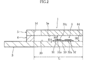
図1ないし図3に示したグルコースセンサ1は、濃度測定装置2に装着して使用するものであり(図4参照)、長矩形状の基板3に対して、スペーサ4を介してカバー5を積層した形態を有している。このグルコースセンサ1においては、各要素3〜5により反応空間6が規定されている。この反応空間6は、矩形断面を有する柱状の空間として規定されており、開口部(導入口)61から導入された試料液を毛細管力を利用して移動させ、かつ導入された試料液を保持することができる。
The
スペーサ4は、基板3の上面30からカバー5の下面5aまでの距離、すなわち反応空間6の高さ寸法を規定するためのものである。このスペーサ4には、先端部が開放したスリット41が形成されている。スリット41は、反応空間6の幅寸法を規定するためのものであり、スリット41における先端の開放部は、反応空間6の内部に試料液を導入するための導入口61を構成するためのものである。
The
カバー5は、排気口51を有している。排気口51は、反応空間6の内部の気体を外部に排出するためのものであり、反応空間6の内部と連通している。したがって、導入口61を介して反応空間6内に試料液が導入された場合には、反応空間6において生じる毛細管力により、試料液がカバー5に形成された排気口51に向けて反応空間6の内部を移動する。
The
図3によく表れているように、基板3の上面30には、作用極31、対極32および試薬部33が形成されている。作用極31および対極32は、全体として基板3の長手方向に延びている。作用極31および対極32の端部31a,32aは、基板3の短手方向に延び、かつ長手方向に並んでいる。一方、作用極31および対極32の端部31b,32bは、後述する濃度測定装置2の第1および第2端子20a,20b(図4参照)と接触させるための端子部を構成している。
As clearly shown in FIG. 3, a working
作用極31および対極32は、たとえばスクリーン印刷、メッキ、あるいはスパッタリングにより、厚み寸法D(図2参照)が20μm以下にされている。好ましくは、作用極31および対極32の厚み寸法Dは、1〜10μmに設定される。作用極31の上面31cからカバー5の下面5aまでの対面距離H1(図2参照)は、45μm以下、好ましくは25〜45μmに設定されている。これは、対面距離H1が不当に大きいと、後述するように血液の温度やヘマトクリット値の影響を受け易い反面、対面距離H1が不当に小さいと、反応空間6の内部において血液を適切に移動させることができなくなるからである。
The working
試薬部33は、たとえばメディエータ(電子伝達物質)および相対的に少量の酸化還元酵素を含む固体状に形成されており、図2および図3によく表れているように、作用極31および対極32の端部31a,32aどうしを橋渡すようにして設けられている。この試薬部33は、血液に対して容易に溶解するものとされている。したがって、反応空間6に血液を導入した場合には、メディエータ、酸化還元酵素およびグルコースを含む液相反応系が構築される。この液相反応系においては、作用極31の上面31cのみならず、反応空間6における広範囲にわたってグルコースの酸化反応と、メディエータの還元反応が生じる。したがって、作用極の表面にメディエータや酸化還元酵素を固定化する場合に比べて、より短時間でより多くのグルコースを酸化させることができる。これにより、測定時間の短縮を図ることができるようになる。
The
メディエータとしては、Ru化合物を使用するのが好ましい。Ru化合物としては、たとえばRu錯体が挙げられる。Ru錯体としては、電子伝達体として機能すればその配位子の種類は特に限定されないが、試薬部33に酸化型の状態で含ませるのが好ましく、たとえば酸化型が下記化学式(2)で示されるものが使用される。
[Ru(NH3)5X]n+ ・・・(2)
化学式(2)におけるXとしては、NH3、ハロゲンイオン、CN、ピリジン、ニコチンアミド、あるいはH2Oが挙げられるが、NH3またはハロゲンイオンが好ましい。一方、化学式におけるn+はXの種類により決定される酸化型(III)錯体の価数を表している。
As the mediator, it is preferable to use a Ru compound. Examples of the Ru compound include a Ru complex. The type of ligand of the Ru complex is not particularly limited as long as it functions as an electron carrier, but is preferably included in the
[Ru (NH 3 ) 5 X] n + (2)
X in the chemical formula (2) includes NH 3 , halogen ion, CN, pyridine, nicotinamide, or H 2 O, and
Ru錯体は、還元型(II)が不安定なために通常は酸化型(III)として存在する。そのため、グルコースセンサ1の試薬部33にRu錯体を混在させた状態で光や水に曝露されたとしても、メディエータが容易に還元してしまうことはない。そのため、メディエータの曝露に起因して測定誤差が生じることを抑制することができるようになる。また、Ru錯体は結晶化しにくく、微粉末状態を適切に維持することができるといった特性を有している。そのため、Ru錯体を用いれば、保存時に試薬部33の溶解性が悪化することもない。さらには、Ru錯体とαGDHやCyGDHとの組み合わせについていえば、Ru錯体の電子伝達速度が大きいために測定時間を短くすることができるといった利点がある。
The Ru complex usually exists as oxidized (III) because the reduced form (II) is unstable. Therefore, even if the Ru complex is mixed in the
一方、酸化還元酵素としては、上述したαGDHまたはCyGDHを使用するのが好ましい。これらの酵素は、グルコースオキシダーゼに比べてグルコースに対する反応速度が大きいといった利点がある。この点からも、測定時間の短縮を図ることができるようになる。 On the other hand, as the oxidoreductase, αGDH or CyGDH described above is preferably used. These enzymes have an advantage that the reaction rate to glucose is higher than that of glucose oxidase. From this point, the measurement time can be shortened.
図4に示したように、濃度測定装置2は、第1および第2端子20a,20b、電圧印加部21、電流値測定部22、検知部23、制御部24、演算部25および表示部26を備えている。
As shown in FIG. 4, the
第1および第2端子20a,20bは、濃度測定装置2に対してグルコースセンサ1を装着した場合に、グルコースセンサ1における作用極31および対極32の端部31b,32bに接触させるためのものである。
The first and
電圧印加部21は、第1および第2端子20a,20bを介して、グルコースセンサ1の作用極31と対極32との間に電圧を印加する際に利用される。電圧印加部21としては、たとえば乾電池または充電池などの直流電源が使用される。
The
電流値測定部22は、作用極31および対極32間への電圧印加時における作用極31とメディエータとの間の電子の授受量を、応答電流値として測定するためのものである。
The current
検知部23は、濃度測定装置2にグルコースセンサ1を装着した後において、電流値測定部22によって測定された電流値に基づいて、試薬部33(図1ないし図3参照)に試料液が供給されたか否かを確認するためのものである。
The
制御部24は、電圧印加部21を制御し、作用極31および対極32の間に電圧が印加される状態(閉回路)と印加されない状態(開回路)とを選択するものである。
The
演算部25は、電流値測定部22により測定された応答電流値に応じて、グルコース濃度の演算を行うものである。演算部25は、たとえばグルコース濃度をアンペロメトリックな手法により演算できるように構成されている。アンペロメトリックな手法を用いれば、クーロメトリックな手法を採用するよりも、短時間で濃度測定を行うことができる。
The calculating
検知部23、制御部24、および演算部25のそれぞれは、たとえばCPUおよびROMやRAMなどのメモリにより構成されるが、検知部23、制御部24、および演算部25の全てを、1つのCPUに対して複数のメモリを接続することにより構成することも可能である。
Each of the
表示部26は、演算部25による演算結果の他、たとえばエラーである旨や操作手順などを表示するためのものであり、たとえば液晶表示装置により構成される。
The
次に、グルコースセンサ1および濃度測定装置2を用いたグルコース濃度の測定の手順について説明する。
Next, a procedure for measuring the glucose concentration using the
図4に良く表れているように、まずグルコースセンサ1を濃度測定装置2に装着する。そうすると、グルコースセンサ1の作用極31および対極32の端部31b,32bが濃度測定装置2の第1および第2端子20a,20bに接触する。この状態では、第1および第2端子20a,20bを介して、作用極31および対極32の間への電圧の印加が可能とされている。実際の測定においては、濃度測定装置2にグルコースセンサ1を装着した時点から、作用極31と対極32との間に定電圧が印加される。Ru錯体は、低電圧でメディエーションを起こすため、Ru錯体を用いる場合には、作用極31および対極32の間に印加する定電圧は、たとえば100〜500mVの範囲に設定される。本実施の形態では、作用極31および対極32の間への定電圧の印加は、グルコース濃度を演算するための応答電流値が測定されるまでは継続して行われているものとする。
As clearly shown in FIG. 4, the
次いで、グルコースセンサ1の導入口61を介して反応空間6に血液を導入する。血液は、毛細管力により導入口61からカバー5に形成された排気口51に向けて反応空間6内を進行する。その過程においては、血液が試薬部33を溶解させる。
Next, blood is introduced into the
一方、試薬部33に血液が供給されれば、酸化還元酵素によりグルコースがグルコノラクトンに酸化されるとともにメディエータが還元型とされる。なお、グルコノラクトンは非酵素的にグルコン酸となる。
On the other hand, when blood is supplied to the
還元型のメディエータは、作用極31および対極32の端部31b,32bを介して作用極31および対極32に定電圧を印加した状態では、作用極の端部31a側に移動し、この端部31aに電子を放出して酸化型のメディエータとなる。したがって、電圧印加部21により作用極31および対極32間に定電圧を印加した状態では、還元型メディエータから付与された電子量が作用極31および第1端子20aを介して電流値測定部22において応答電流として測定される。この応答電流値は、電圧印加によって試薬部33を移動した還元型のメディエータに由来する電子量に相関するものであり、いわゆる拡散電流と呼ばれるものである。
In a state where a constant voltage is applied to the working
一方、電流値測定部22において測定された応答電流値は、検知部23においてモニタリングされており、応答電流値が閾値を越えた時点で、検知部23は試薬部33に血液が供給され、試薬部33が溶解したことを検知する。検知部23において血液が供給されたことが検知された場合には、この検知から一定時間経過したか否かが検知部23により判断される。
On the other hand, the response current value measured by the current
検知部23において一定時間が経過したと判断された場合には、電流値測定部22において応答電流値を測定し、この応答電流値に基づいて、演算部25においてグルコース濃度が演算される。グルコース濃度の演算は、応答電流値を電圧値に換算した後に、この電圧値を、予め作成しておいた電圧値とグルコース濃度との関係を示す検量線に当てはめることにより演算される。演算部25における演算結果は、たとえば表示部26において表示される。
When the
作用極31に接触している還元型のメディエータは、即座に作用極31に対して電子を放出して酸化型となるが、作用極31から一定距離離れた還元型のメディエータであっても、作用極31に対して電子を放出して酸化型となる。以下、作用極31に対して還元型のメディエータが電子を放出可能な領域を電子放出領域、作用極31に対して還元型のメディエータが電子を放出することができない領域を非電子放出領域ということとする。
The reduced mediator that is in contact with the working
後述する実施例から推測できるように、電子放出領域における作用極の表面からの距離は、45μmよりも小さくなることはない。したがって、図5Aに示したように、作用極31の上面31cからカバー5の下面5aまでの対面距離H1が比較的に大きい場合、たとえば対面距離H1が50μm以上の場合には、作用極31の直上においては、電子放出領域70の上方に非電子放出領域71が存在することとなる。
As can be inferred from the examples described later, the distance from the surface of the working electrode in the electron emission region does not become smaller than 45 μm. Therefore, as shown in FIG. 5A, when the facing distance H1 from the
これに対して、本願のグルコースセンサ1のように、作用極31の上面31cからカバー5の下面5aまでの対面距離H1が45μm以下に設定されている場合には、図5Bに示したように、電子放出領域70における作用極31の直上に位置する部分の厚み寸法(以下、単に「電子放出領域70の厚み寸法」という)が対面距離H1に一致し、この電子放出領域70の厚み寸法は、図5Aに示した場合と同等かもしくはそれよりも小さくなる。
On the other hand, when the facing distance H1 from the
このように、対面距離H1が大きい場合(図5A参照)と小さい場合(図5B参照)とでは、作用極31の直上における様子が異なったものとなる。その結果、後述する本発明の実施例からも推測できるように、対面距離H1の大小により、還元型メディエータが消費される様子が異なったものとなる。
Thus, when the facing distance H1 is large (see FIG. 5A) and small (see FIG. 5B), the situation immediately above the working
ここで、電圧非印加状態において、電子放出領域に存在する還元型のメディエータ(以下、「非拡散メディエータ」という)の濃度と、非電子放出領域に存在する還元型のメディエータ(以下、「拡散メディエータ」という)の濃度とが同一である系を考える。 Here, in the state where no voltage is applied, the concentration of the reduced mediator (hereinafter referred to as “non-diffusion mediator”) existing in the electron emission region and the reduced mediator (hereinafter referred to as “diffusion mediator” present in the non-electron emission region). ”) Is considered to be the same concentration.
図5Aに示した対面距離H1が大きいケースでは、電子放出領域70(点線で囲まれた部分)の厚み寸法が大きいために、電圧印加時に非拡散メディエータの全てが酸化されるわけではない。したがって、非拡散メディエータが一定量ずつ消費され、これに起因して電子放出領域70と非電子放出領域71との間に還元型メディエータの濃度差が生じる。これにより、電子放出領域70に対しては、その上方および側方から、拡散メディエータが拡散してくる。その後は、電子放出領域70に存在する還元型メディエータの酸化、および電子放出領域70に対する拡散メディエータの拡散が重畳的に生じる。このため、対面距離H1が大きいケースでは、大きく分けて、初期は非拡散メディエータの消費、中期は非拡散メディエータおよび拡散メディエータの消費、後期は拡散メディエータの消費というプロセスを経ることとなる。
In the case where the facing distance H1 shown in FIG. 5A is large, not all of the non-diffusion mediator is oxidized when a voltage is applied because the electron emission region 70 (portion surrounded by a dotted line) has a large thickness dimension. Therefore, the non-diffusion mediator is consumed by a certain amount, and this causes a difference in concentration of the reduced mediator between the
ここで、拡散メディエータの拡散速度は、電子放出領域70と非電子放出領域71との間における還元型メディエータの濃度差に加えて、拡散媒体(血液)の温度や移動抵抗(血液のヘマトクリット値)の影響を受ける。したがって、対面距離H1が大きいケースでは、血液の温度やヘマトクリット値の影響が経時的に徐々に大きくなる。
Here, in addition to the concentration difference of the reduced mediator between the
これに対して、対面距離H1が小さいケース(図5B参照)では、電子放出領域70の厚み寸法が小さいために、初期において非拡散メディエータが殆ど全て消費され、次いで電子放出領域への拡散メディエータの拡散および消費が生じる。このため、対面距離H1が小さいケースでは、大きく分けて、初期は非拡散メディエータの消費、後期は拡散メディエータの消費というプロセスを経ることとなる。したがって、対面距離H1が小さいケースでは、血液の温度やヘマトクリット値の影響を受けにくい段階と、それらの影響を大きく受ける段階とに分かれることになる。
On the other hand, in the case where the facing distance H1 is small (see FIG. 5B), since the thickness dimension of the
対面距離H1が電子放出領域の厚み寸法と一致するケースでは、電子放出領域に対する拡散メディエータの拡散は、電子放出領域の側方のみから行われる。そのため、対面距離H1が電子放出領域の厚み寸法よりも大きく、電子放出領域の側方および上方から拡散メディエータが拡散してくる場合に比べれば、対面距離H1が小さい場合には、拡散メディエータの拡散速度などが、測定電流値に与える影響は小さいといえる。とくに、血液の温度やヘマトクリット値の影響を受けにくい段階においては、拡散メディエータの挙動が測定電流値に与える影響は小さい。したがって、対面距離H1を電子放出領域の厚み寸法と同程度、もしくはそれよりも小さくすれば、血液の温度やヘマトクリット値の影響を受けにくく、電圧印加開始からの短い時間範囲(測定時間が短い範囲)における再現性が良好なものとなる。 In the case where the facing distance H1 matches the thickness dimension of the electron emission region, diffusion of the diffusion mediator with respect to the electron emission region is performed only from the side of the electron emission region. Therefore, when the facing distance H1 is smaller than the case where the facing distance H1 is larger than the thickness dimension of the electron emitting region and the diffusion mediator diffuses from the side and above the electron emitting region, the diffusion of the diffusion mediator It can be said that the influence of the speed etc. on the measured current value is small. In particular, the influence of the behavior of the diffusion mediator on the measured current value is small at a stage that is not easily affected by the blood temperature or hematocrit value. Accordingly, if the facing distance H1 is set to be equal to or smaller than the thickness dimension of the electron emission region, it is less affected by the blood temperature and hematocrit value, and a short time range from the start of voltage application (a range where the measurement time is short). ) In the reproducibility.
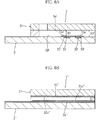
本発明に係るグルコースセンサは、上述した実施の形態には限定されず、種々に設計変更可能である。たとえば作用極31および対極32は、少なくとも一部が反応空間6の内部に臨んでいればよく、たとえば図6Aに示した構成を採用することもできる。
The glucose sensor according to the present invention is not limited to the above-described embodiment, and various design changes can be made. For example the working
図6Aに示したグルコースセンサ1′は、基板3′に凹部35′,36′を形成し、この凹部35′,36′に作用極31′および対極32′を埋設形成したものである。 The glucose sensor 1 'shown in FIG. 6A is formed by forming recesses 35' and 36 'in a substrate 3' and embedding and forming a working electrode 31 'and a counter electrode 32' in the recesses 35 'and 36'.
作用極31′および対極32′の上面31c′,32c′は、図示したように基板3′の上面30′と面一となるようにしてもよく、また面一でなくてもよい。
The
このグルコースセンサ1′では、対面距離H1′は、作用極31′の上面31c′からカバー5′の下面5a′までの距離として定義され、作用極31′および対極32′の上面31c′,32c′が基板3′の上面30′と面一の場合には、対面距離H1′は、基板3′とカバー5′との間の距離H2′に一致する。
In this glucose sensor 1 ', the facing distance H1' is defined as the distance from the
図6Bに示したグルコースセンサ1″は、本発明の参考例である。このグルコースセンサ1″は、基板3″に作用極31″を形成し、カバー5″に対極32″を形成したものである。 A
本発明は、スペーサによって反応空間の高さ寸法が規定された分析用具に限らず、反応空間となるべき凹部が形成された基板に対して、カバーを接合した構成の分析用具に対しても適用することができる。 The present invention is not limited to an analysis tool in which the height of the reaction space is defined by a spacer, but is also applied to an analysis tool having a structure in which a cover is joined to a substrate on which a recess to be a reaction space is formed. can do.
以下においては、本発明に係るグルコースセンサが、応答電流値の測定において、血液中の血球や温度による影響が小さく、短時間で精度良くグルコース濃度を測定することができることについて、実施例1〜4を通して実証する。 In the following, the glucose sensor according to the present invention is less affected by blood cells and temperature in blood in measuring the response current value, and can measure the glucose concentration with high accuracy in a short time. To demonstrate through.
[グルコースセンサの作成]
実施例1〜4においては、図1ないし図3に示したのと同様な構成のグルコースセンサを用いて評価した。各実施例において用いたグルコースセンサは、反応空間6の長さ寸法L(図2参照)、幅寸法W(図1参照)、作用極31および対極32の厚さ寸法D(図2参照)を、それぞれ3.4mm、1.5mm、10μmとした。グルコースセンサにおける対面距離H1、基板3とカバー5との間の距離H2(図2参照)、および試薬部33の構成については、下記表1に示した通りとした。
[Create glucose sensor]
In Examples 1 to 4, the evaluation was performed using a glucose sensor having the same configuration as that shown in FIGS. The glucose sensor used in each example has the length L of the reaction space 6 (see FIG. 2), the width W (see FIG. 1), and the thickness D of the working

本案グルコースセンサ1,2および比較グルコースセンサ1については、試薬部33を、電子伝達層および酵素含有層からなる2層構造とした。電子伝達層は、基板3上に電子伝達物質を含む第1材料液を0.4μL塗布した後に第1材料液を送風乾燥(30℃、10%Rh)することにより形成した。酵素含有層は、電子伝達層上に、酸化還元酵素を含む第2材料液を0.3μL塗布した後に第2材料液を送風乾燥(30℃、10%Rh)することにより形成した。
In the proposed
第1材料液は、下記表2に(1)〜(4)で示した材料をその番号通りの順序で混合した混合液を、1〜3日放置した後、この混合液に電子伝達物質を添加することにより調製した。電子伝達物質としては、[Ru(NH3)6]Cl3(同仁化学研究所「LM722」)を使用した。 The first material liquid is a mixture obtained by mixing the materials shown in (1) to (4) in the following Table 2 in the order of their numbers. After leaving for 1 to 3 days, an electron transfer substance is added to the mixture. Prepared by adding. [Ru (NH 3 ) 6 ] Cl 3 (Dojindo Laboratories “LM722”) was used as the electron transfer substance.
表2などにおいて、SWNはルーセンタイトSWNの略号であり、CHAPSは3−[(3−cholamidopropyl)dimethylammonio]propanesulfonic acidの略号であり、ACESはN−(2−acetamido)−2−aminoethanesulfonic acidの略号である。SWNとしては、コープケミカル(株)製「3150」を使用し、CHAPSとしては同仁化学研究所製「KC062」を使用し、ACESとしては同仁化学研究所製「ED067」を使用した。なお、ACES溶液はpHが7.5となるように調製した。 In Table 2 and the like, SWN is an abbreviation for Lucentite SWN, CHAPS is an abbreviation for 3-[(3-cholaminopropylo) dimethyllamino] propanesulphonic acid, and ACES is an abbreviation for N- (2-acetamido) -2-aminoethanesulfide. It is. As SWN, “3150” manufactured by Coop Chemical Co., Ltd. was used, “KC062” manufactured by Dojindo Laboratories was used as CHAPS, and “ED067” manufactured by Dojindo Laboratories was used as ACES. The ACES solution was prepared so that the pH was 7.5.
一方、第2材料液は、酸化還元酵素を0.1%CHAPSに溶解させることにより調製した。酸化還元酵素としては、CyGDH(グルコース脱水素活性が800U/mg)を使用した。CyGDHについては、上述した通りである。 On the other hand, the second material solution was prepared by dissolving oxidoreductase in 0.1% CHAPS. CyGDH (glucose dehydrogenation activity 800 U / mg) was used as the oxidoreductase. CyGDH is as described above.
これに対して、本案グルコースセンサ3,4および比較グルコースセンサ2については、試薬部33を、フェリシアン化カリウムとフェロシアン化カリウムが共存する構成とした。これは、酸化還元酵素の触媒能、その他の要因の影響を除外し、純粋に、対面距離H1の高さが再現性に与える影響を判断するためである。より具体的には、試薬部33は、基板3上に材料液を保持させることにより液相として形成した。材料液としては、フェリシアン化カリウムが20mM、フェロシアン化カリウムが24mM、塩化カリウムが1.5Mとなるように調製されたものを用いた。
On the other hand, in the proposed
実施例1(ヘマトクリット値の影響の検討)
本実施例においては、本案グルコースセンサ1,2および比較グルコースセンサ1を用いて、ヘマトクリット(Hct)値が応答電流値に与える影響を評価した。
この評価においては、血液としては、グルコース濃度が412mg/dL、Hct値が19%、42%、あるいは69%のいずれかのものを用いた。
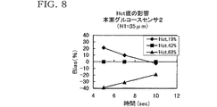
Example 1 (Examination of influence of hematocrit value)
In this example, the influence of the hematocrit (Hct) value on the response current value was evaluated using the proposed
In this evaluation, blood having a glucose concentration of 412 mg / dL and an Hct value of 19%, 42%, or 69% was used.
作用極31と対極32との間への電圧印加は、印加電圧値を200mVとして血液の供給と同時に開始し、応答電流値は、電圧印加の開始から5sec、7sec、および10sec後に測定した。各Hct値の血液については、5回ずつ応答電流値を測定した。
The voltage application between the working
応答電流値の測定結果は、本案グルコースセンサ1については図7に、本案グルコースセンサ2については図8に、比較グルコースセンサ1については図9にそれぞれ示した。また、図7〜図9においては、横軸を時間(sec)、縦軸をBias(%)として示してある。Bias(%)は、Hct値が42%のときの応答電流値を基準とし、この基準値に対するずれ量を示すものであり、各図においては、Bias(%)は5回の測定の平均値として示してある。
The measurement results of the response current values are shown in FIG. 7 for the proposed
図7〜図9を比較すれば分かるように、電圧印加時間の如何に拘わらず、対面距離H1が小さいほどBiasが小さくなる傾向にある。したがって、対面距離H1が小さいほど、血液のHct値の影響が小さくなる傾向が伺える。 As can be seen by comparing FIGS. 7 to 9, Bias tends to be smaller as the facing distance H1 is smaller, regardless of the voltage application time. Therefore, it can be seen that the smaller the facing distance H1, the smaller the influence of the Hct value of blood.
実施例2(温度の影響)
本実施例においては、本案グルコースセンサ1,2および比較グルコースセンサ1を用いて、血液の温度が応答電流値に与える影響を評価した。
Example 2 (Influence of temperature)
In this example, the influence of the blood temperature on the response current value was evaluated using the proposed
この評価においては、血液としては、Hct値が42%、グルコース濃度が100.0mg/dL、422.0mg/dL、あるいは636.0mg/dLのいずれかで、温度が5℃、25℃あるいは45℃に調製されたものを用いた。 In this evaluation, the blood has an Hct value of 42%, a glucose concentration of 100.0 mg / dL, 422.0 mg / dL, or 636.0 mg / dL, and a temperature of 5 ° C., 25 ° C. or 45 ° What was prepared at ℃ was used.
作用極31と対極32との間への電圧印加は、印加電圧値を200mVとして血液の供給開始から行い、応答電流値は、電圧印加開始から5sec後に測定した。各グルコース濃度の血液については、5回ずつ応答電流値を測定した。
The voltage application between the working
応答電流値の測定結果は、本案グルコースセンサ1については図10に、本案グルコースセンサ2については図11に、比較グルコースセンサ1については図12にそれぞれ示した。また、図10〜図12においては、横軸を温度(℃)、縦軸をBias(%)として各グルコース濃度について個別に示した。ここで、Bias(%)は、温度が25℃のときの応答電流値を基準とし、この基準に対するずれ量を示すものであり、各図においては、Bias(%)は5回の測定の平均値として示してある。
The measurement results of the response current values are shown in FIG. 10 for the proposed
図10〜図12を比較すれば分かるように、グルコース濃度および電圧印加時間の如何に拘わらず、対面距離H1が小さいほどBiasが小さくなる傾向にある。したがって、対面距離H1が小さいほど、血液の温度の影響が小さくなる傾向が伺える。 As can be seen by comparing FIGS. 10 to 12, Bias tends to decrease as the facing distance H <b> 1 decreases regardless of the glucose concentration and the voltage application time. Therefore, it can be seen that the smaller the facing distance H1, the smaller the influence of the blood temperature.
実施例3(測定レンジの評価)
本実施例では、本案グルコースセンサ1を用いて、測定レンジを評価した。測定レンジは、グルコース濃度と応答電流値との関係(直線性)により評価した。
Example 3 (Evaluation of measurement range)
In this example, the measurement range was evaluated using the proposed
この評価においては、血液としては、Hct値が42%、グルコース濃度が0mg/dL、100mg/dL、200mg/dL、400mg/dL、610mg/dL、805mg/dLあるいは980mg/dLのものを用いた。作用極31と対極32との間への電圧印加は、印加電圧値を200mVとして血液の供給開始から行い、応答電流値は、電圧印加の開始から3sec後に測定した。各グルコース濃度の血液については、10回ずつ応答電流値を測定した。
In this evaluation, blood having an Hct value of 42% and a glucose concentration of 0 mg / dL, 100 mg / dL, 200 mg / dL, 400 mg / dL, 610 mg / dL, 805 mg / dL or 980 mg / dL was used. . Voltage application between the working
応答電流値の測定結果は、図13に示した。ただし、図13においては、応答電流値(μA)は、10回の測定の平均値として示してある。 The measurement result of the response current value is shown in FIG. However, in FIG. 13, the response current value (μA) is shown as an average value of 10 measurements.
図13から分かるように、本案グルコースセンサ1では、グルコース濃度が0〜1000mg/dLの範囲で高い直線性を示しており、グルコース濃度が比較的に大きい場合(600mg/dL以上)であっても、適切にグルコース濃度を測定できるといえる。したがって、本案グルコースセンサ1のように、酸化還元酵素としてCyGDHを、メディエータとしてRu錯体を使用すれば、対面距離H1を小さくして設定しても、3秒程度の短い測定時間で、0〜1000mg/dLの範囲にあるグルコースの濃度を適切に測定できるといえる。
As can be seen from FIG. 13, the
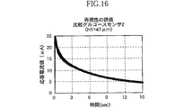
実施例4(再現性の評価)
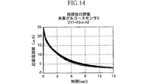
本実施例では、本案グルコースセンサ3,4および比較グルコースセンサ2を用いて、複数回の応答電流値の測定のタイムコースおよび相対標準偏差C.V.(%)のタイムコースに基づいて、応答電流値の再現性を評価した。
Example 4 (Evaluation of reproducibility)
In the present embodiment, using the proposed
この評価においては、血液としてHct値が42%、グルコース濃度が412mg/dLのものを用いた。作用極31と対極32との間への電圧印加は、印加電圧値を200mVとして血液の供給開始から5秒後に開始し、応答電流値は、電圧印加の開始から、50msec毎に経時的に測定した。
In this evaluation, blood having an Hct value of 42% and a glucose concentration of 412 mg / dL was used. Voltage application between the working
タイムコースの測定結果については、図14〜図16に示した。これらの図においては、5回分の測定の応答電流値のタイムコースを同時に示してあり、図14は本案グルコースセンサ3、図15は本案グルコースセンサ4、図16は比較グルコースセンサ2を用いたときの結果をそれぞれ示している。一方、図17には、C.V.(%)のタイムコースを示した。このタイムコースは、応答電流値のタイムコースを得るための5回の応答電流値の測定に基づいて作成した。
The measurement results of the time course are shown in FIGS. In these figures, the time courses of response current values for five measurements are shown at the same time. FIG. 14 shows the proposed
図14〜図16から分かるように、本案グルコースセンサ3,4では、比較グルコースセンサ2と同様に応答電流値のタイムコースに殆どバラツキが見られず、複数回の測定において良好な再現性が得られた。一方、図17から分かるように、本案グルコースセンサ3では、電圧印加開始初期、すなわち電圧印加開始から0.5〜3.0(sec)の時間範囲において、本案グルコースセンサ4や比較グルコースセンサ2に比べてC.V.が小さく、C.V.値が概ね2.5%以下と小さくなっている。本案グルコースセンサ4では、電圧印加開始から3.0〜7.0(sec)の時間範囲において、比較グルコースセンサ2に比べてC.V.が小さく、C.V.値が概ね2.5%以下と小さくなっている。これらの結果から分かるように、対面距離H1を小さく設定すれば、電圧印加開始から短い時間範囲において、再現性が良好なものとなっている。したがって、再現性の観点からは、対面距離H1を小さく設定したグルコースセンサは、短い測定時間に適したものであるといえる。
As can be seen from FIGS. 14 to 16, in the proposed
Claims (14)
互いに対向した状態で間隔を隔てて配置され、かつ上記反応空間を規定する第1および第2板材を備えるとともに、上記第1および第2面は、上記第1および第2板材の厚み方向に直交する方向に広がりをもつ面であり、
上記第1板材の一面に設けられ、かつ少なくとも一部が上記反応空間に臨むとともに、試料液に電圧を印加するために利用される第1および第2電極をさらに備えており、
上記対面距離は、上記第1または第2電極の上面から、上記第2板材における当該電極の上面に対面する部分までの最小距離である、薄型分析用具。 Holding the sample solution, Rutotomoni comprises a reaction space where the reagent portion which dissolves is placed when the sample liquid is held, a portion of the reaction space, is defined by the first and second surfaces facing each other cage and the facing distance between the first and second surface a thin type analysis tool that is set to 45μm or less,
The first and second plate members are arranged in a state of being opposed to each other and spaced apart from each other and define the reaction space, and the first and second surfaces are orthogonal to the thickness direction of the first and second plate members. It is a surface with a spread in the direction to
A first electrode and a second electrode provided on one surface of the first plate member and facing at least a part of the reaction space and used to apply a voltage to the sample solution;
The thin analytical tool, wherein the facing distance is a minimum distance from an upper surface of the first or second electrode to a portion of the second plate member facing the upper surface of the electrode.
[Ru(NH 3 ) 5 X] n+ ・・・(1)
上記化学式(1)においては、Xは、NH 3 、ハロゲンイオン、CN、ピリジン、ニコチンアミド、あるいはH 2 Oであり、n+はXの種類により決定される酸化型Ru(III)錯体の価数を表している。 The thin analytical tool according to claim 5, wherein the Ru compound is represented by the following chemical formula (1).
[Ru (NH 3 ) 5 X] n + (1)
In the above chemical formula (1), X is NH 3 , halogen ion, CN, pyridine, nicotinamide, or H 2 O, and n + is the valence of the oxidized Ru (III) complex determined by the type of X Represents .
上記酸化還元酵素は、ブルクホルデリア属に属する微生物に由来のグルコース脱水素酵素である、請求項4に記載の薄型分析用具。 The electron transfer material is a Ru compound,
The thin analytical tool according to claim 4 , wherein the oxidoreductase is a glucose dehydrogenase derived from a microorganism belonging to the genus Burkholderia .
上記酸化還元酵素は、グルコース脱水素活性を有し、かつ還元条件下でのSDS−ポリアクリルアミドゲル電気泳動における分子量が約60kDaであるαサブユニットと、還元条件下でのSDS−ポリアクリルアミドゲル電気泳動における分子量が約43kDaであるチトクロムCと、を有している、請求項12に記載の薄型分析用具。
[Ru(NH 3 ) 5 X] n+ ・・・(2)
上記化学式(2)においては、Xは、NH 3 、ハロゲンイオン、CN、ピリジン、ニコチンアミド、あるいはH 2 Oであり、n+はXの種類により決定される酸化型Ru(III)錯体の価数を表している。 The Ru compound is represented by the following chemical formula (2):
The oxidoreductase has glucose dehydrogenation activity and has an α subunit having a molecular weight of about 60 kDa in SDS-polyacrylamide gel electrophoresis under reducing conditions, and SDS-polyacrylamide gel electricity under reducing conditions. The thin analytical tool according to claim 12 , comprising cytochrome C having a molecular weight of about 43 kDa in electrophoresis .
[Ru (NH 3 ) 5 X] n + (2)
In the above chemical formula (2), X is NH 3 , halogen ion, CN, pyridine, nicotinamide, or H 2 O, and n + is the valence of the oxidized Ru (III) complex determined by the type of X Represents.
Applications Claiming Priority (3)
| Application Number | Priority Date | Filing Date | Title |
|---|---|---|---|
| JP2002370930 | 2002-12-20 | ||
| JP2002370930 | 2002-12-20 | ||
| PCT/JP2003/016132 WO2004061444A1 (en) | 2002-12-20 | 2003-12-16 | Thin analyzing device |
Publications (2)
| Publication Number | Publication Date |
|---|---|
| JPWO2004061444A1 JPWO2004061444A1 (en) | 2006-05-18 |
| JP4352153B2 true JP4352153B2 (en) | 2009-10-28 |
Family
ID=32708153
Family Applications (1)
| Application Number | Title | Priority Date | Filing Date |
|---|---|---|---|
| JP2004564495A Expired - Lifetime JP4352153B2 (en) | 2002-12-20 | 2003-12-16 | Thin analysis tool |
Country Status (6)
| Country | Link |
|---|---|
| US (1) | US20060231396A1 (en) |
| EP (1) | EP1577665B1 (en) |
| JP (1) | JP4352153B2 (en) |
| CN (1) | CN100487442C (en) |
| AU (1) | AU2003289373A1 (en) |
| WO (1) | WO2004061444A1 (en) |
Families Citing this family (65)
| Publication number | Priority date | Publication date | Assignee | Title |
|---|---|---|---|---|
| US6036924A (en) | 1997-12-04 | 2000-03-14 | Hewlett-Packard Company | Cassette of lancet cartridges for sampling blood |
| US6391005B1 (en) | 1998-03-30 | 2002-05-21 | Agilent Technologies, Inc. | Apparatus and method for penetration with shaft having a sensor for sensing penetration depth |
| US8641644B2 (en) | 2000-11-21 | 2014-02-04 | Sanofi-Aventis Deutschland Gmbh | Blood testing apparatus having a rotatable cartridge with multiple lancing elements and testing means |
| US9226699B2 (en) | 2002-04-19 | 2016-01-05 | Sanofi-Aventis Deutschland Gmbh | Body fluid sampling module with a continuous compression tissue interface surface |
| DE60234598D1 (en) | 2001-06-12 | 2010-01-14 | Pelikan Technologies Inc | SELF-OPTIMIZING LANZET DEVICE WITH ADAPTANT FOR TEMPORAL FLUCTUATIONS OF SKIN PROPERTIES |
| ATE485766T1 (en) | 2001-06-12 | 2010-11-15 | Pelikan Technologies Inc | ELECTRICAL ACTUATING ELEMENT FOR A LANCET |
| US8337419B2 (en) | 2002-04-19 | 2012-12-25 | Sanofi-Aventis Deutschland Gmbh | Tissue penetration device |
| US7981056B2 (en) | 2002-04-19 | 2011-07-19 | Pelikan Technologies, Inc. | Methods and apparatus for lancet actuation |
| EP1404234B1 (en) | 2001-06-12 | 2011-02-09 | Pelikan Technologies Inc. | Apparatus for improving success rate of blood yield from a fingerstick |
| US7749174B2 (en) | 2001-06-12 | 2010-07-06 | Pelikan Technologies, Inc. | Method and apparatus for lancet launching device intergrated onto a blood-sampling cartridge |
| US9427532B2 (en) | 2001-06-12 | 2016-08-30 | Sanofi-Aventis Deutschland Gmbh | Tissue penetration device |
| US7682318B2 (en) | 2001-06-12 | 2010-03-23 | Pelikan Technologies, Inc. | Blood sampling apparatus and method |
| US7025774B2 (en) | 2001-06-12 | 2006-04-11 | Pelikan Technologies, Inc. | Tissue penetration device |
| US9795747B2 (en) | 2010-06-02 | 2017-10-24 | Sanofi-Aventis Deutschland Gmbh | Methods and apparatus for lancet actuation |
| US9314194B2 (en) | 2002-04-19 | 2016-04-19 | Sanofi-Aventis Deutschland Gmbh | Tissue penetration device |
| US7901362B2 (en) | 2002-04-19 | 2011-03-08 | Pelikan Technologies, Inc. | Method and apparatus for penetrating tissue |
| US7648468B2 (en) | 2002-04-19 | 2010-01-19 | Pelikon Technologies, Inc. | Method and apparatus for penetrating tissue |
| US8579831B2 (en) | 2002-04-19 | 2013-11-12 | Sanofi-Aventis Deutschland Gmbh | Method and apparatus for penetrating tissue |
| US8267870B2 (en) | 2002-04-19 | 2012-09-18 | Sanofi-Aventis Deutschland Gmbh | Method and apparatus for body fluid sampling with hybrid actuation |
| US7229458B2 (en) | 2002-04-19 | 2007-06-12 | Pelikan Technologies, Inc. | Method and apparatus for penetrating tissue |
| US7717863B2 (en) | 2002-04-19 | 2010-05-18 | Pelikan Technologies, Inc. | Method and apparatus for penetrating tissue |
| US7491178B2 (en) | 2002-04-19 | 2009-02-17 | Pelikan Technologies, Inc. | Method and apparatus for penetrating tissue |
| US7547287B2 (en) | 2002-04-19 | 2009-06-16 | Pelikan Technologies, Inc. | Method and apparatus for penetrating tissue |
| US7674232B2 (en) | 2002-04-19 | 2010-03-09 | Pelikan Technologies, Inc. | Method and apparatus for penetrating tissue |
| US7226461B2 (en) | 2002-04-19 | 2007-06-05 | Pelikan Technologies, Inc. | Method and apparatus for a multi-use body fluid sampling device with sterility barrier release |
| US9248267B2 (en) | 2002-04-19 | 2016-02-02 | Sanofi-Aventis Deustchland Gmbh | Tissue penetration device |
| US7892183B2 (en) | 2002-04-19 | 2011-02-22 | Pelikan Technologies, Inc. | Method and apparatus for body fluid sampling and analyte sensing |
| US7909778B2 (en) | 2002-04-19 | 2011-03-22 | Pelikan Technologies, Inc. | Method and apparatus for penetrating tissue |
| US8702624B2 (en) | 2006-09-29 | 2014-04-22 | Sanofi-Aventis Deutschland Gmbh | Analyte measurement device with a single shot actuator |
| US8784335B2 (en) | 2002-04-19 | 2014-07-22 | Sanofi-Aventis Deutschland Gmbh | Body fluid sampling device with a capacitive sensor |
| US7175642B2 (en) | 2002-04-19 | 2007-02-13 | Pelikan Technologies, Inc. | Methods and apparatus for lancet actuation |
| US7976476B2 (en) | 2002-04-19 | 2011-07-12 | Pelikan Technologies, Inc. | Device and method for variable speed lancet |
| US8221334B2 (en) | 2002-04-19 | 2012-07-17 | Sanofi-Aventis Deutschland Gmbh | Method and apparatus for penetrating tissue |
| US9795334B2 (en) | 2002-04-19 | 2017-10-24 | Sanofi-Aventis Deutschland Gmbh | Method and apparatus for penetrating tissue |
| US7371247B2 (en) | 2002-04-19 | 2008-05-13 | Pelikan Technologies, Inc | Method and apparatus for penetrating tissue |
| US7331931B2 (en) | 2002-04-19 | 2008-02-19 | Pelikan Technologies, Inc. | Method and apparatus for penetrating tissue |
| US7291117B2 (en) | 2002-04-19 | 2007-11-06 | Pelikan Technologies, Inc. | Method and apparatus for penetrating tissue |
| US7297122B2 (en) | 2002-04-19 | 2007-11-20 | Pelikan Technologies, Inc. | Method and apparatus for penetrating tissue |
| US7232451B2 (en) | 2002-04-19 | 2007-06-19 | Pelikan Technologies, Inc. | Method and apparatus for penetrating tissue |
| US8574895B2 (en) | 2002-12-30 | 2013-11-05 | Sanofi-Aventis Deutschland Gmbh | Method and apparatus using optical techniques to measure analyte levels |
| DK1633235T3 (en) | 2003-06-06 | 2014-08-18 | Sanofi Aventis Deutschland | Apparatus for sampling body fluid and detecting analyte |
| WO2006001797A1 (en) | 2004-06-14 | 2006-01-05 | Pelikan Technologies, Inc. | Low pain penetrating |
| US8282576B2 (en) | 2003-09-29 | 2012-10-09 | Sanofi-Aventis Deutschland Gmbh | Method and apparatus for an improved sample capture device |
| EP1680014A4 (en) | 2003-10-14 | 2009-01-21 | Pelikan Technologies Inc | Method and apparatus for a variable user interface |
| US7822454B1 (en) | 2005-01-03 | 2010-10-26 | Pelikan Technologies, Inc. | Fluid sampling device with improved analyte detecting member configuration |
| EP1706026B1 (en) | 2003-12-31 | 2017-03-01 | Sanofi-Aventis Deutschland GmbH | Method and apparatus for improving fluidic flow and sample capture |
| US8828203B2 (en) | 2004-05-20 | 2014-09-09 | Sanofi-Aventis Deutschland Gmbh | Printable hydrogels for biosensors |
| EP1765194A4 (en) | 2004-06-03 | 2010-09-29 | Pelikan Technologies Inc | Method and apparatus for a fluid sampling device |
| US8652831B2 (en) | 2004-12-30 | 2014-02-18 | Sanofi-Aventis Deutschland Gmbh | Method and apparatus for analyte measurement test time |
| JPWO2006090873A1 (en) * | 2005-02-25 | 2008-07-24 | 有限会社アルティザイム・インターナショナル | Fuel cell type enzyme sensor |
| TWI285739B (en) * | 2005-12-20 | 2007-08-21 | Univ Feng Chia | Electrochemical testing device |
| US7943022B2 (en) | 2007-09-04 | 2011-05-17 | Lifescan, Inc. | Analyte test strip with improved reagent deposition |
| WO2009126900A1 (en) | 2008-04-11 | 2009-10-15 | Pelikan Technologies, Inc. | Method and apparatus for analyte detecting device |
| EP2172767A1 (en) * | 2008-10-06 | 2010-04-07 | Sony Corporation | A sensor for thiol analytes |
| US9375169B2 (en) | 2009-01-30 | 2016-06-28 | Sanofi-Aventis Deutschland Gmbh | Cam drive for managing disposable penetrating member actions with a single motor and motor and control system |
| CN113092562B (en) | 2009-04-17 | 2024-03-29 | 环球生物医疗感测仪私人有限公司 | Electrochemical on-board control detection |
| JP5422647B2 (en) * | 2009-05-29 | 2014-02-19 | パナソニック株式会社 | Biosensor system and method for measuring concentration of analyte |
| US8965476B2 (en) | 2010-04-16 | 2015-02-24 | Sanofi-Aventis Deutschland Gmbh | Tissue penetration device |
| US9772310B2 (en) | 2011-07-28 | 2017-09-26 | Kyocera Corporation | Biosensor |
| JP5684767B2 (en) | 2011-09-26 | 2015-03-18 | アークレイ株式会社 | Lactic acid sensor |
| JP6059457B2 (en) * | 2011-10-31 | 2017-01-11 | アークレイ株式会社 | Analysis tool and analysis method |
| JP5900923B2 (en) * | 2012-05-22 | 2016-04-06 | 住化エンバイロメンタルサイエンス株式会社 | Evaluation method of allergen reduction function |
| BR112014032201A2 (en) * | 2012-06-25 | 2017-06-27 | Bioengineering Laboratories Llc | enzyme electrode |
| EP3093656A1 (en) * | 2015-05-13 | 2016-11-16 | ARKRAY, Inc. | Analytical tool and analytical system |
| JP6925933B2 (en) * | 2017-10-25 | 2021-08-25 | アークレイ株式会社 | Electrodes and biosensors for measuring ascorbic acid |
Family Cites Families (16)
| Publication number | Priority date | Publication date | Assignee | Title |
|---|---|---|---|---|
| JP2796983B2 (en) * | 1989-03-03 | 1998-09-10 | テルモ株式会社 | Glucose sensor |
| JP3063393B2 (en) * | 1992-05-12 | 2000-07-12 | 東陶機器株式会社 | Biosensor and manufacturing method thereof |
| US5437999A (en) * | 1994-02-22 | 1995-08-01 | Boehringer Mannheim Corporation | Electrochemical sensor |
| DE69809391T2 (en) * | 1997-02-06 | 2003-07-10 | Therasense Inc | SMALL VOLUME SENSOR FOR IN-VITRO DETERMINATION |
| JPH1194790A (en) * | 1997-09-12 | 1999-04-09 | Nok Corp | Biosensor |
| US6071391A (en) * | 1997-09-12 | 2000-06-06 | Nok Corporation | Enzyme electrode structure |
| JP4256007B2 (en) * | 1999-01-29 | 2009-04-22 | アークレイ株式会社 | Biosensor manufacturing method |
| US20020092612A1 (en) | 2000-03-28 | 2002-07-18 | Davies Oliver William Hardwicke | Rapid response glucose sensor |
| JP4177662B2 (en) * | 2000-07-24 | 2008-11-05 | 松下電器産業株式会社 | Biosensor |
| WO2002036779A1 (en) * | 2000-10-31 | 2002-05-10 | Koji Sode | Novel glucose dehydrogenase and process for producing the dehydrogenase |
| US6540890B1 (en) * | 2000-11-01 | 2003-04-01 | Roche Diagnostics Corporation | Biosensor |
| US7232510B2 (en) * | 2000-11-30 | 2007-06-19 | Matsushita Electric Industrial Co., Ltd. | Biosensor, measuring instrument for biosensor, and method of quantifying substrate |
| US6837988B2 (en) * | 2001-06-12 | 2005-01-04 | Lifescan, Inc. | Biological fluid sampling and analyte measurement devices and methods |
| ATE505724T1 (en) * | 2001-09-14 | 2011-04-15 | Arkray Inc | METHOD, APPARATUS AND APPARATUS FOR CONCENTRATION MEASUREMENT |
| CN102533939B (en) | 2002-06-17 | 2013-11-20 | 爱科来株式会社 | Method of measuring glucose concentration and glucose sensor with the use of glucose dehydrogenase |
| EP1557663B1 (en) | 2002-11-01 | 2007-08-01 | ARKRAY, Inc. | Measuring instrument provided with sold component concentrating means |
-
2003
- 2003-12-16 EP EP03780809.4A patent/EP1577665B1/en not_active Expired - Lifetime
- 2003-12-16 US US10/539,421 patent/US20060231396A1/en not_active Abandoned
- 2003-12-16 JP JP2004564495A patent/JP4352153B2/en not_active Expired - Lifetime
- 2003-12-16 AU AU2003289373A patent/AU2003289373A1/en not_active Abandoned
- 2003-12-16 CN CNB2003801069377A patent/CN100487442C/en not_active Expired - Lifetime
- 2003-12-16 WO PCT/JP2003/016132 patent/WO2004061444A1/en active Application Filing
Also Published As
| Publication number | Publication date |
|---|---|
| EP1577665A4 (en) | 2012-05-16 |
| CN100487442C (en) | 2009-05-13 |
| EP1577665B1 (en) | 2013-06-26 |
| WO2004061444A1 (en) | 2004-07-22 |
| CN1729394A (en) | 2006-02-01 |
| EP1577665A1 (en) | 2005-09-21 |
| AU2003289373A1 (en) | 2004-07-29 |
| US20060231396A1 (en) | 2006-10-19 |
| JPWO2004061444A1 (en) | 2006-05-18 |
Similar Documents
| Publication | Publication Date | Title |
|---|---|---|
| JP4352153B2 (en) | Thin analysis tool | |
| US10895550B2 (en) | Multi-region and potential test sensors, methods, and systems | |
| US11091790B2 (en) | Determining analyte concentration from variant concentration distribution in measurable species | |
| US7291256B2 (en) | Mediator stabilized reagent compositions and methods for their use in electrochemical analyte detection assays | |
| JP4385219B2 (en) | Concentration measurement method | |
| KR100729307B1 (en) | Method of measuring glucose concentration and glucose sensor with the use of glucose dehydrogenase | |
| EP0794429B1 (en) | Cholesterol sensor | |
| WO2005066638A1 (en) | Analytical instrument having improved arrangement of reagent section and analytical method | |
| CN101878428B (en) | Porous particle reagent compositions, devices, and methods for biosensors | |
| ES2317163T3 (en) | PROCEDURE AND COMPOSITIONS TO CHARACTERIZE AN ENZYME OF A REACTIVE OXIDOREDUCTION SYSTEM. | |
| US20220112536A1 (en) | Oxygen-insensitive electrochemical biosensor and methods of use thereof | |
| JP2023532189A (en) | ANALYTE SENSOR AND METHOD OF MANUFACTURING AN ANALYTE SENSOR |
Legal Events
| Date | Code | Title | Description |
|---|---|---|---|
| A621 | Written request for application examination |
Free format text: JAPANESE INTERMEDIATE CODE: A621 Effective date: 20061114 |
|
| A131 | Notification of reasons for refusal |
Free format text: JAPANESE INTERMEDIATE CODE: A131 Effective date: 20090106 |
|
| A521 | Request for written amendment filed |
Free format text: JAPANESE INTERMEDIATE CODE: A523 Effective date: 20090306 |
|
| TRDD | Decision of grant or rejection written | ||
| A01 | Written decision to grant a patent or to grant a registration (utility model) |
Free format text: JAPANESE INTERMEDIATE CODE: A01 Effective date: 20090623 |
|
| A01 | Written decision to grant a patent or to grant a registration (utility model) |
Free format text: JAPANESE INTERMEDIATE CODE: A01 |
|
| A61 | First payment of annual fees (during grant procedure) |
Free format text: JAPANESE INTERMEDIATE CODE: A61 Effective date: 20090709 |
|
| R150 | Certificate of patent or registration of utility model |
Ref document number: 4352153 Country of ref document: JP Free format text: JAPANESE INTERMEDIATE CODE: R150 Free format text: JAPANESE INTERMEDIATE CODE: R150 |
|
| FPAY | Renewal fee payment (event date is renewal date of database) |
Free format text: PAYMENT UNTIL: 20120807 Year of fee payment: 3 |
|
| FPAY | Renewal fee payment (event date is renewal date of database) |
Free format text: PAYMENT UNTIL: 20130807 Year of fee payment: 4 |
|
| R250 | Receipt of annual fees |
Free format text: JAPANESE INTERMEDIATE CODE: R250 |
|
| R250 | Receipt of annual fees |
Free format text: JAPANESE INTERMEDIATE CODE: R250 |
|
| R250 | Receipt of annual fees |
Free format text: JAPANESE INTERMEDIATE CODE: R250 |
|
| R250 | Receipt of annual fees |
Free format text: JAPANESE INTERMEDIATE CODE: R250 |
|
| R250 | Receipt of annual fees |
Free format text: JAPANESE INTERMEDIATE CODE: R250 |
|
| R250 | Receipt of annual fees |
Free format text: JAPANESE INTERMEDIATE CODE: R250 |
|
| R250 | Receipt of annual fees |
Free format text: JAPANESE INTERMEDIATE CODE: R250 |
|
| R250 | Receipt of annual fees |
Free format text: JAPANESE INTERMEDIATE CODE: R250 |
|
| R250 | Receipt of annual fees |
Free format text: JAPANESE INTERMEDIATE CODE: R250 |
|
| R250 | Receipt of annual fees |
Free format text: JAPANESE INTERMEDIATE CODE: R250 |
|
| R250 | Receipt of annual fees |
Free format text: JAPANESE INTERMEDIATE CODE: R250 |
|
| R250 | Receipt of annual fees |
Free format text: JAPANESE INTERMEDIATE CODE: R250 |
|
| EXPY | Cancellation because of completion of term |