JP4348255B2 - Vehicle seat - Google Patents
Vehicle seat Download PDFInfo
- Publication number
- JP4348255B2 JP4348255B2 JP2004245553A JP2004245553A JP4348255B2 JP 4348255 B2 JP4348255 B2 JP 4348255B2 JP 2004245553 A JP2004245553 A JP 2004245553A JP 2004245553 A JP2004245553 A JP 2004245553A JP 4348255 B2 JP4348255 B2 JP 4348255B2
- Authority
- JP
- Japan
- Prior art keywords
- seat back
- side frame
- vehicle seat
- elastic body
- frame
- Prior art date
- Legal status (The legal status is an assumption and is not a legal conclusion. Google has not performed a legal analysis and makes no representation as to the accuracy of the status listed.)
- Expired - Fee Related
Links
Images


Classifications
-
- B—PERFORMING OPERATIONS; TRANSPORTING
- B60—VEHICLES IN GENERAL
- B60N—SEATS SPECIALLY ADAPTED FOR VEHICLES; VEHICLE PASSENGER ACCOMMODATION NOT OTHERWISE PROVIDED FOR
- B60N2/00—Seats specially adapted for vehicles; Arrangement or mounting of seats in vehicles
- B60N2/24—Seats specially adapted for vehicles; Arrangement or mounting of seats in vehicles for particular purposes or particular vehicles
- B60N2/42—Seats specially adapted for vehicles; Arrangement or mounting of seats in vehicles for particular purposes or particular vehicles the seat constructed to protect the occupant from the effect of abnormal g-forces, e.g. crash or safety seats
- B60N2/427—Seats or parts thereof displaced during a crash
- B60N2/42727—Seats or parts thereof displaced during a crash involving substantially rigid displacement
- B60N2/42745—Seats or parts thereof displaced during a crash involving substantially rigid displacement of the back-rest
-
- B—PERFORMING OPERATIONS; TRANSPORTING
- B60—VEHICLES IN GENERAL
- B60N—SEATS SPECIALLY ADAPTED FOR VEHICLES; VEHICLE PASSENGER ACCOMMODATION NOT OTHERWISE PROVIDED FOR
- B60N2/00—Seats specially adapted for vehicles; Arrangement or mounting of seats in vehicles
- B60N2/68—Seat frames
- B60N2/682—Joining means
-
- B—PERFORMING OPERATIONS; TRANSPORTING
- B60—VEHICLES IN GENERAL
- B60N—SEATS SPECIALLY ADAPTED FOR VEHICLES; VEHICLE PASSENGER ACCOMMODATION NOT OTHERWISE PROVIDED FOR
- B60N2/00—Seats specially adapted for vehicles; Arrangement or mounting of seats in vehicles
- B60N2/80—Head-rests
- B60N2/806—Head-rests movable or adjustable
-
- B—PERFORMING OPERATIONS; TRANSPORTING
- B60—VEHICLES IN GENERAL
- B60N—SEATS SPECIALLY ADAPTED FOR VEHICLES; VEHICLE PASSENGER ACCOMMODATION NOT OTHERWISE PROVIDED FOR
- B60N2/00—Seats specially adapted for vehicles; Arrangement or mounting of seats in vehicles
- B60N2/80—Head-rests
- B60N2/888—Head-rests with arrangements for protecting against abnormal g-forces, e.g. by displacement of the head-rest
Description
本発明は、車両後方から衝突された場合の乗員のむち打ちを防止することが可能な車両用シートに関する。 The present invention relates to a vehicle seat that can prevent whiplash of an occupant when a collision is caused from the rear of the vehicle.
車両用シートには、通常シートバックの上方にヘッドレストが設けられており、乗員が着座した状態では、乗員の頭部とヘッドレストとの間には所定の隙間があり、車両後方から衝突された場合、身体は前方に移動するのに対し、頭部は後方に残ることで、頸部に負荷がかかりむち打ち症になることがある。 A vehicle seat is usually provided with a headrest above the seat back, and when the occupant is seated, there is a predetermined gap between the occupant's head and the headrest, and the vehicle seat collides from the rear of the vehicle. The body moves forward while the head remains behind, which can cause a load on the neck and cause whiplash.
そこで、頭部とヘッドレスト間の隙間を小さくして、被害を最小限に抑えることは可能ではあるが、通常使用状態でも頭部がヘッドレストに常に触れたり、頭部を少し動かすことでヘッドレストと干渉して不快に感じるという問題がある。 Although it is possible to minimize the damage by reducing the gap between the head and the headrest, the head always touches the headrest even during normal use, or moves the head slightly to interfere with the headrest. There is a problem that it feels uncomfortable.
また、受圧部に連結されたヘッドレストを揺動自在に取り付けるとともにコイルスプリングにより常時後方に付勢し、車両後方からの衝突に際し、受圧部に入力された荷重によりコイルスプリングの付勢力に抗してヘッドレストを前方に移動させることも提案されているが、衝突後、頭部に当接したヘッドレストが直ちに元の位置に復帰する構成のため、やはり頸部に負荷がかかるという問題がある(例えば、特許文献1参照。)。 In addition, the headrest connected to the pressure receiving portion is swingably attached and is always urged rearward by a coil spring, and in the event of a collision from the rear of the vehicle, the load input to the pressure receiving portion resists the urging force of the coil spring. It has also been proposed to move the headrest forward, but after the collision, the headrest that abuts the head immediately returns to its original position, so there is still a problem that the neck is loaded (for example, (See Patent Document 1).
そこで、車両後方からの衝突時、ヘッドレストを前方に移動させ、さらにその位置に保持する機構も提案されている(例えば、特許文献2あるいは3参照。)。
Therefore, a mechanism has also been proposed in which the headrest is moved forward at the time of a collision from the rear of the vehicle and further held at that position (for example, see
特許文献2に記載の車両用シートにあっては、車両後方からの衝突時、前方に移動したヘッドレストをその位置に保持する機構としてラチェット機構を採用しているが、衝突後、前方に移動したヘッドレストを元の位置に復帰させることができなかった。また、衝突後、ヘッドレストが前方に保持されることで、頭部の衝撃はある程度軽減されるものの、まだまだ不十分であった。
In the vehicle seat described in
また、特許文献3に記載の車両用シートにおいては、同様にラチェット機構を採用しているが、衝突後、前方に移動したヘッドレストを元の位置に復帰させる解除手段が設けられている。しかしながら、衝突後、ヘッドレストはやはり前方に保持される構成で、機構も複雑でコストアップになるという問題がある。 The vehicle seat described in Patent Document 3 similarly employs a ratchet mechanism, but is provided with a release means for returning the headrest moved forward after the collision to the original position. However, there is a problem that the headrest is still held forward after the collision, and the mechanism is complicated and the cost is increased.
本発明は、従来技術の有するこのような問題点に鑑みてなされたものであり、通常は乗員頭部とヘッドレスト間の隙間は確保しておき、車両後方からの衝突に際し、ヘッドレストを前方に移動させるとともに、衝突後、ヘッドレストを元の位置に復帰可能な構成とし、復帰時抵抗を持たせることで頸部の負荷を軽減することができる簡素な構成の車両用シートを提供することを目的としている。 The present invention has been made in view of the above-described problems of the prior art. Usually, a clearance between the passenger's head and the headrest is secured, and the headrest is moved forward in the event of a collision from the rear of the vehicle. The purpose of the present invention is to provide a vehicle seat with a simple configuration that can reduce the load on the neck by providing a resistance at the time of return, with a configuration in which the headrest can be returned to its original position after a collision. Yes.
上記目的を達成するために、本発明のうちで請求項1に記載の発明は、シートクッションと、該シートクッションに対し傾倒自在に取り付けられたシートバックと、該シートバックの上部に取り付けられたヘッドレストとを有する車両用シートにおいて、シートクッションフレームに取り付けられた一対のサイドフレームと、該サイドフレームに回転ヒンジを介して取り付けられたシートバックフレームとを備え、該シートバックフレーム及び前記サイドフレームのいずれか一方に弾性体を取り付け、前記シートバックフレーム及び前記サイドフレームの他方に前記弾性体をガイドするガイド部を形成するとともに、該ガイド部に前記弾性体を保持する保持部を形成し、通常着座時には、前記弾性体を前記保持部に保持して前記シートバックフレームを前記サイドフレームに固定する一方、車両後方より所定値以上の荷重が入力された場合には、人体の後方への移動により腰部が前記シートバックフレームの下部を押し前記弾性体が変形して前記保持部より離脱し前記ガイド部に沿って後方に移動することで、前記シートバックフレームが前記回転ヒンジを中心に揺動し、前記ヘッドレストを前方に移動させるようにしたことを特徴とする。 In order to achieve the above object, the invention according to claim 1 is a seat cushion, a seat back that is tiltably attached to the seat cushion, and an upper portion of the seat back. A vehicle seat having a headrest, comprising: a pair of side frames attached to a seat cushion frame; and a seat back frame attached to the side frame via a rotation hinge; the seat back frame and the side frame; An elastic body is attached to one of them, and a guide portion for guiding the elastic body is formed on the other of the seat back frame and the side frame, and a holding portion for holding the elastic body is formed on the guide portion. When seated, the elastic body is held by the holding portion and the seat back While the frame is fixed to the side frame, when a load of a predetermined value or more is input from the rear of the vehicle, the waist moves the lower part of the seat back frame and the elastic body deforms due to the movement of the human body to the rear. The seat back frame swings about the rotary hinge and moves the headrest forward by detaching from the holding portion and moving rearward along the guide portion.
また、請求項2に記載の発明は、前記弾性体としてバネ部材を使用し、前記保持部の形状を前記保持部により保持される前記バネ部材の部位と相補形状としたことを特徴とする。
The invention according to
さらに、請求項3に記載の発明は、前記サイドフレームに前記ガイド部を形成するとともに、前記シートバックフレームの下部に前記バネ部材を取り付けたことを特徴とする。 Furthermore, the invention described in claim 3 is characterized in that the guide portion is formed on the side frame, and the spring member is attached to a lower portion of the seat back frame.
また、請求項4に記載の発明は、前記ガイド部が前記サイドフレームに形成されたガイド孔で、前記保持部が前記ガイド孔の近傍に形成された凹部であることを特徴とする。 According to a fourth aspect of the present invention, the guide portion is a guide hole formed in the side frame, and the holding portion is a recess formed in the vicinity of the guide hole.
また、請求項5に記載の発明は、前記バネ部材と前記保持部との間に案内部材を介装し、前記保持部の形状を前記保持部により保持される前記案内部材の部位と相補形状としたことを特徴とする。 According to a fifth aspect of the present invention, a guide member is interposed between the spring member and the holding portion, and the shape of the holding portion is complementary to the shape of the guide member held by the holding portion. It is characterized by that.
また、請求項6に記載の発明は、前記バネ部材が皿バネであることを特徴とする。
The invention according to
また、請求項7に記載の発明は、前記皿バネに放射状の突出部を形成したことを特徴とする。 The invention according to claim 7 is characterized in that a radial protrusion is formed on the disc spring.
また、請求項8に記載の発明は、前記ガイド部を前記サイドフレームに形成されたガイド孔と該ガイド孔の両側に形成された隆起部で構成するとともに、前記保持部を前記ガイド孔の両側に形成された二つの凹部で構成し、前記弾性体に形成された二つの突起を前記二つの凹部にそれぞれ嵌入させたことを特徴とする。 According to an eighth aspect of the present invention, the guide portion is composed of a guide hole formed in the side frame and a raised portion formed on both sides of the guide hole, and the holding portion is formed on both sides of the guide hole. And two protrusions formed on the elastic body are fitted into the two recesses, respectively.
また、請求項9に記載の発明は、前記弾性体が前記保持部から後方に向かって移動を開始するときの荷重を調節できるようにしたことを特徴とする。 The invention according to claim 9 is characterized in that a load when the elastic body starts moving backward from the holding portion can be adjusted.
また、請求項10に記載の発明は、前記シートバックフレームの下方に受圧板を取り付け、車両後方より所定値以上の荷重が入力された場合には、人体の移動による荷重を前記受圧板に伝達するようにしたことを特徴とする。
In the invention according to
また、請求項11に記載の発明は、前記シートバックフレームが前記回転ヒンジを中心に揺動して前記ヘッドレストが前方に移動した後、前記ヘッドレストあるいは前記シートバックフレームに荷重を加えることにより前記弾性体を前記保持部に復帰させるようにしたことを特徴とする。
The invention according to
本発明によれば、通常着座時には、弾性体をガイド部に形成された保持部に保持させてシートバックフレームをサイドフレームに固定し、例えば車両後方よりの衝突等により所定値以上の荷重が入力された場合には、人体の後方への移動により腰部がシートバックフレームの下部を押し弾性体が変形して保持部より離脱しガイド部に沿って後方に移動することで、ヘッドレストを前方に移動させるようにしたので、弾性体の弾力性で乗員の頸部の損傷を防止することができる。また、ヘッドレストは弾性体の弾力性により前方位置に保持されるが、衝突後のリバウンド(体重移動)によりヘッドレストが元の位置に復帰するに際し、ある程度の抵抗が生じることで、頸部の負荷が軽減される。 According to the present invention, at the time of normal sitting, the elastic body is held by the holding portion formed in the guide portion and the seat back frame is fixed to the side frame, and a load of a predetermined value or more is input due to a collision from the rear of the vehicle, for example. In this case, the waist part pushes the lower part of the seat back frame due to the movement of the human body backward, the elastic body deforms and moves away from the holding part and moves backward along the guide part, thereby moving the headrest forward. Since the elastic body is elastic, damage to the occupant's neck can be prevented. In addition, the headrest is held at the front position by the elasticity of the elastic body, but when the headrest returns to its original position due to rebound (weight shift) after the collision, a certain amount of resistance is generated, which reduces the load on the neck. It is reduced.
以下、本発明の実施の形態について、図面を参照しながら説明する。
本発明にかかる車両用シートは、車体フロアに取り付けられるシートクッションと、シートクッションに対し傾倒自在に取り付けられるシートバックとを備えている。
Hereinafter, embodiments of the present invention will be described with reference to the drawings.
The vehicle seat according to the present invention includes a seat cushion attached to a vehicle body floor and a seat back attached to the seat cushion so as to be tiltable.
実施の形態1.
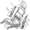
図1は、本発明の実施の形態1にかかる車両用シートのシートバックを示しており、シートクッションフレーム(図11あるいは図12参照)にリクライニングアジャスタ2を介して取り付けられる左右一対のサイドフレーム4と、サイドフレーム4に取り付けられるシートバックフレーム6と、シートバックフレーム6に取り付けられるパッド材8と、パッド材8を被覆する表皮材10とにより構成されている。ヘッドレスト11(図4参照)は、シートバックフレーム6の上部に取り付けられる。
Embodiment 1 FIG.
FIG. 1 shows a seat back of a vehicle seat according to a first embodiment of the present invention, and a pair of left and
左右のリクライニングアジャスタ2は連結軸12を介して連結されており、一方のリクライニングアジャスタ2に取り付けられた操作レバー14を操作することにより、サイドフレーム4は所望の角度に設定される。
The left and right reclining
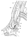
図2及び図3に示されるように、リクライニングアジャスタ2はシートクッションフレームに取り付けられる下部ブラケット16と、下部ブラケット16に対し傾倒自在に取り付けられた上部ブラケット18とを備えているが、リクライニングアジャスタ2は本発明の主眼ではないので、詳細説明は省略する。
As shown in FIGS. 2 and 3, the reclining
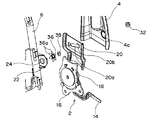
リクライニングアジャスタ2の上部ブラケット18には、サイドフレームインナー20が取り付けられており、サイドフレームインナー20には、シートバックフレーム6に取り付けられたボルト(後述)が遊挿されるガイド孔(ガイド部)20aが形成されている。また、ガイド孔20aの前端部には弾性部材(後述)を保持するための凹部(弾性体保持部)20bが形成されている。サイドフレームインナー20の上部には、サイドフレーム4が接合されており、サイドフレームインナー20に形成された凹部20bに対向するサイドフレーム4には、ナット挿入孔4aが穿設されている。さらに、サイドフレーム4の上部には回転ヒンジ挿入孔4bが穿設されている。なお、上述したガイド孔20aは、回転ヒンジ挿入孔4bを中心とする円弧状の長孔形状に形成されている。
A side frame inner 20 is attached to the
一方、シートバックフレーム6は、サイドフレームインナー20に形成された凹部20bに対向する部位にブラケット22が接合されており、このブラケット22に凹部20bに向かって突出する第1のボルト24が取り付けられている。また、サイドフレーム4に形成された回転ヒンジ挿入孔4bに対向するシートバックフレーム6には、別のブラケット26が接合されており、このブラケット26に回転ヒンジ挿入孔4bに向かって突出する回転ヒンジとしての第2のボルト28が取り付けられている。
On the other hand, the seat back
シートバックフレーム6をサイドフレーム4及びサイドフレームインナー20に取り付けるに際し、第1のボルト24が皿バネ30の中心孔30aとサイドフレームインナー20の凹部20bの中心孔(ガイド孔20aの先端部)に挿通されるとともに、第2のボルト28がサイドフレーム4の回転ヒンジ挿入孔4bに挿通される。また、サイドフレーム4のナット挿入孔4aを介して第1のナット32が第1のボルト24に螺合され、第2のナット34が第2のボルト28に螺合される。
When the
なお、弾性体あるいはバネ部材としての皿バネ30は、外方に向かって円錐状の内端部が、この内端部と相補形状をなすサイドフレームインナー20の凹部20bの円錐状の傾斜面に嵌入して保持されており、皿バネ30の外端部はブラケット22の平坦面に当接している。
The
上記構成の本発明にかかる車両用シートは、通常の着座時には、皿バネ30がサイドフレームインナー20の凹部20bに保持されているので、シートバックフレーム6はサイドフレーム4に固定されており、この状態で乗員の上体の荷重をシートバックフレーム6で支持している。また、シートバックフレーム6の上部に取り付けられたヘッドレスト11は、乗員の頭部とは所定の間隔をおいて離隔している。
In the vehicle seat according to the present invention having the above-described configuration, the
一方、例えば車両後方から衝突(後突)され、後方から所定値以上の荷重が入力された場合、人体は相対的にシートバックに押しつけられる。このとき、人体の後方への移動により腰部がシートバックフレーム6の下部を後方に押すことになるので、皿バネ30は変形して(圧縮されて)サイドフレームインナー20の凹部20bから離脱し、第1のボルト24とともにガイド孔20aに沿ってガイド孔20aの後端部に向かって移動する。したがって、シートバックフレーム6は第2のボルト28を回転ヒンジとして揺動し、ヘッドレスト11は乗員の頭部に向かって移動して乗員の頭部を支持することになる。
On the other hand, for example, when a collision (rear collision) occurs from the rear of the vehicle and a load greater than a predetermined value is input from the rear, the human body is relatively pressed against the seat back. At this time, since the waist part pushes the lower part of the seat back
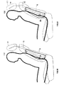
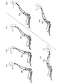
図4は、通常の着座状態(a)と、後突時のシートバックフレーム6及びヘッドレスト11の作動状態(b)を示している。
FIG. 4 shows a normal seating state (a) and an operating state (b) of the seat back
なお、第1のボルト24と第2のボルト28との間隔は、第2のボルト28とヘッドレスト11の高さ方向の間隔より大きく設定されているが、後突時に乗員頭部の荷重がヘッドレスト11に遅れて加えられると、腰部が押し戻されヘッドレスト11は元の位置に向かって移動する。しかしながら、後突時の皿バネ30の変形は弾性範囲内の変形であることから、ある程度の抵抗が生じ、乗員の頚部の負荷が軽減される。
In addition, although the space | interval of the 1st volt |
また、ヘッドレスト11が元の位置に完全に復帰できなかった場合、ヘッドレスト11に後方への荷重を加えることにより、あるいは、シートバックフレーム6の下部に前方への荷重を加えることにより、第2のボルト28及び皿バネ30はガイド孔20aに沿って前方に向かって移動し、皿バネ30は凹部20bに再び保持される(元の位置に復帰する)。
Further, when the
なお、上記実施の形態において、皿バネ30及び第1のボルト24のガイド孔20aをサイドフレームインナー20に形成したが、サイドフレームインナーをサイドフレームと一体的に形成し、サイドフレームの一部にガイド孔を形成する構成も可能である。
In the above embodiment, the
また、上記実施の形態においては、皿バネ30を弾性体として採用したが、後述するように、皿バネに放射状の突出部を複数設けて、突出部がブラケット22の平坦面に当接するようにしてもよい。この場合、後突時に皿バネの突出部が容易に変形し、安定した荷重で皿バネがガイド孔20aに沿って移動する。
In the above embodiment, the
さらに、皿バネ30あるいは複数の突出部を有する皿バネと凹部20bとの間に円錐状の斜面を有する樹脂製あるいは金属製ワッシャを案内部材として介装することもできる。
Further, a resin or metal washer having a conical slope may be interposed as a guide member between the
図5及び図6は、複数の突出部36aを有する皿バネ36と凹部20bとの間に上述した円錐状の斜面を有するワッシャ38を介装した構成を示している。この構成においては、ワッシャ38の円錐状斜面が、この斜面と相補形状をなすサイドフレームインナー20の凹部20bの円錐状の傾斜面に嵌入して保持されており、ワッシャ38の反対側平坦面は、皿バネ36の円錐形状の内端部外面と当接している。また、皿バネ36の複数の突出部36aがブラケット22の平坦面に当接している。
5 and 6 show a configuration in which the
なお、図5及び図6の構成において、皿バネ36に代えて、円筒状のゴム体や圧縮バネやウェーブワッシャ等を使用することもできる。
5 and 6, a cylindrical rubber body, a compression spring, a wave washer, or the like can be used instead of the
また、皿バネ30,36をシートバックフレーム6に設けられた第1のボルト24に取り付けるようにしたが、シートバックフレーム6にガイド孔を有するブラケットを接合するとともに、サイドフレームインナー20に設けられたボルトに皿バネを取り付けることもできる。
Further, the disc springs 30 and 36 are attached to the
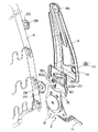
さらに、図7及び図8に示されるように、サイドフレームインナー20に形成されたガイド孔20aの前端部を除く両側にガイド孔20aと略平行に延びる凸部40を形成することも可能で、この場合、ガイド孔20aの前端部には皿バネ30(あるいは36)を保持するための凹部は形成されていない。
Further, as shown in FIGS. 7 and 8, it is also possible to form
この構成において、通常の着座時には、図8(a)に示されるように、皿バネ30がガイド孔20aの前端部に保持されている。一方、後突時には、図8(b)に示されるように、皿バネ30は変形して(圧縮されて)凸部40に乗り上げ、第1のボルト24とともにガイド孔20aに沿ってガイド孔20aの後端部に向かって移動する。したがって、シートバックフレーム6は第2のボルト28を回転ヒンジとして揺動し、ヘッドレスト11は乗員の頭部に向かって移動して乗員の頭部を支持することになる。
In this configuration, during normal seating, the
また、図9に示されるように、金属製のボール42を介して後突時にシートバックフレーム6を揺動させることも可能である。
Further, as shown in FIG. 9, the seat back
すなわち、サイドフレーム4の下端部をサイドフレームインナー20に接合し、サイドフレームインナー20に凹部44をサイドフレーム4に向かって円錐状に形成するとともに、シートバックフレーム6に接合されたブラケット22にボール収容孔22aを形成して、ボール42をサイドフレームインナー20の凹部44とブラケット22のボール収容孔22aに収容している。また、ブラケット22には板ばね等の弾性体46の一端が螺着されており、この弾性体46の他端でボール42を凹部44に向かって付勢している。
That is, the lower end portion of the
この構成は、通常の着座時には、ボール42は弾性体46の弾性力により凹部44内に保持されている。一方、後突時には、シートバックフレーム6の下部に後方への荷重が加わるので、ボール42を付勢している弾性体46の他端部が内方に向かって持ち上げられる。その結果、ボール42は凹部44から離脱して、ボール収容孔22aに収容された状態で後方に向かって移動する。したがって、シートバックフレーム6は第2のボルト28を回転ヒンジとして揺動し、ヘッドレスト11は乗員の頭部に向かって移動して乗員の頭部を支持することになる。
In this configuration, during normal seating, the
さらに、図10に示される構成も可能である。
詳述すると、図10に示されるように、サイドフレーム4の下端部をサイドフレームインナー20に接合し、サイドフレームインナー20に前後方向に延びる矩形長孔20cを形成するとともに、シートバックフレーム6に接合されたブラケット22にも同一形状の矩形長孔22bを形成し、略L字状に折曲され基端部がブラケット22に螺着された板ばね等の弾性体48の先端部を二つの矩形長孔20c,22bに遊挿している。弾性体48の先端後部にはテーパ状の切欠部48aが形成されており、この切欠部48aがサイドフレームインナー20の矩形長孔20cの後縁に対向するように設定されている。
Furthermore, the configuration shown in FIG. 10 is also possible.
More specifically, as shown in FIG. 10, the lower end portion of the
この構成において、通常の着座時には、弾性体48の先端部は二つの矩形長孔20c,22bに遊挿され保持されている。一方、後突時には、シートバックフレーム6の下部に後方への荷重が加わるので、弾性体48の弾性力に抗して弾性体48の先端後部に形成されたテーパ状の切欠部48aがサイドフレームインナー20の矩形長孔20cの後縁に乗り上げ、内方に向かって持ち上げられる。その結果、弾性体48の先端部は矩形長孔20cから離脱して後方に向かって移動する。したがって、シートバックフレーム6は第2のボルト28を回転ヒンジとして揺動し、ヘッドレスト11は乗員の頭部に向かって移動して乗員の頭部を支持することになる。
In this configuration, at the time of normal seating, the tip of the
実施の形態2.
図11及び図12は、本発明の実施の形態2にかかる車両用シートを示しており、以下上述した実施の形態1との相違点を主に説明する。
11 and 12 show a vehicle seat according to the second embodiment of the present invention, and differences from the above-described first embodiment will be mainly described below.
リクライニングアジャスタ2の上部ブラケット18には、サイドフレーム50の下端部が取り付けられており、サイドフレーム50には、シートバックフレーム52の下端部近傍に取り付けられたボルト(後述)が遊挿されるガイド孔(ガイド部)50aが形成されている。
The lower bracket of the
図13に示されるように、ガイド孔50aの後端部を除く両側には、ガイド孔50aと略平行に延びるとともに外方に向かって凸状の隆起部54が形成されており、隆起部54の中間部には、弾性部材(後述)を保持するための凹部(弾性体保持部)54aが形成されている。さらに、サイドフレーム50の上部には回転ヒンジ挿入孔50bが穿設されている。なお、上述したガイド孔50aは、回転ヒンジ挿入孔50bを中心とする円弧状の長孔形状に形成されている。
As shown in FIG. 13, on both sides except for the rear end portion of the
一方、上部にヘッドレスト11が取り付けられたシートバックフレーム52は、略逆U字状に形成されており、図12及び図14に示されるように、その下端部には揺動リンク56の一端が回動自在に取り付けられ、揺動リンク56の他端はサイドフレーム50の下端部に形成された切欠50cに嵌入している。また、揺動リンク56の中間部にはコイルスプリング58の一端が係止され、コイルスプリング58の他端がサイドフレーム50の下端部に係止されることで、揺動リンク56はその他端が切欠50cに向かって付勢されている。
On the other hand, the seat back
さらに、サイドフレーム50に形成されたガイド孔50aに対向するシートバックフレーム52には、ガイド孔50aに向かって突出する第1のボルト60が取り付けられており、サイドフレーム50に形成された回転ヒンジ挿入孔50bに対向するシートバックフレーム52には、回転ヒンジ挿入孔50bに向かって突出する回転ヒンジとしての第2のボルト62が取り付けられている。
Further, a
また、シートバックフレーム52の両側部には複数のS字バネ64の両端が固定されており、下方に位置する二つのS字バネ64の間には着座者の腰部に対向する受圧板66が設けられ、その両端はS字バネ64と同様、シートバックフレーム52の両側部に固定されている。なお、S字バネ64はシートバックフレーム52をカバーするパッド材(図示せず)の裏面に当接しているのに対し、受圧板66はパッド材の裏面とは離隔しており、人が座ったときに初めて受圧板66はパッド材と当接する。
Further, both ends of a plurality of S-shaped
シートバックフレーム52をサイドフレーム50に取り付けるに際し、第1のボルト60がサイドフレーム50のガイド孔50aと略長円形あるいは菱形状の弾性部材(板バネ)68の中心孔68aに挿通されるとともに、第2のボルト62がサイドフレーム50の回転ヒンジ挿入孔50bに挿通された後、第1及び第2のボルト60,62にはナット70,72が螺合される。
When the seat back
なお、弾性部材68の両端にはサイドフレーム50に向かって凸状の突起74が、サイドフレーム50に形成された隆起部54の凹部54aと相補形状をなすように形成されており、第1のボルト60とナット70とを螺合させるに際し、突起74が隆起部54の凹部54aに嵌入する。このとき、第1のボルト60はガイド孔50aの前端部に位置している。
In addition,
上記構成の本発明にかかる車両用シートは、通常の着座時には、弾性部材68の突起74がサイドフレーム50に形成された隆起部54の凹部54aに嵌入して保持されているので、シートバックフレーム52はサイドフレーム50に固定されており、この状態で乗員の上体の荷重をシートバックフレーム52で支持している。また、シートバックフレーム52の上部に取り付けられたヘッドレスト11は、乗員の頭部とは所定の間隔をおいて離隔している。
In the vehicle seat according to the present invention having the above-described configuration, the
一方、例えば車両後方から衝突(後突)され、後方から所定値以上の荷重が入力された場合、人体は相対的にシートバックに押しつけられる。このとき、人体の後方への移動により腰部が受圧板66を後方に押すことになるので、弾性部材68が変形し、弾性部材68の突起74は隆起部54の凹部54aから離脱し、第1のボルト60とともにガイド孔50aに沿ってガイド孔50aの後端部に向かって移動する。したがって、シートバックフレーム52は第2のボルト62を回転ヒンジとして揺動し、ヘッドレスト11は乗員の頭部に向かって移動して乗員の頭部を支持することになる。
On the other hand, for example, when a collision (rear collision) occurs from the rear of the vehicle and a load greater than a predetermined value is input from the rear, the human body is relatively pressed against the seat back. At this time, the lumbar part pushes the
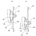
図15(a)及び(b)は、通常の着座状態と、後突時のシートバックフレーム52及びヘッドレスト11の作動状態をそれぞれ示している。
FIGS. 15A and 15B show a normal seating state and an operating state of the seat back
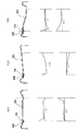
なお、図16(a)に示されるように、隆起部54は後方に向かってなだらかなテーパ形状を呈していることから、作動時(ヘッドレスト11の前方移動時)には、弾性部材68が容易に後方へ移動できるように作用し、ヘッドレスト11を元の位置に復帰させる時には、ある程度の抵抗を与えることになる。
As shown in FIG. 16A, since the raised
後突試験により、人体からの荷重は最初腰部が高く、その後胸部や頭部が高くなることが分かっており、本発明においては、腰部の荷重が高くなった時点でシートバックフレーム52の揺動機構が働いて、一旦ヘッドレスト11が前方へ移動し頭部を保持する。その後、胸部や頭部の荷重が高くなったときには、上述したテーパ形状の作用により、頭部や胸部の衝撃を吸収しながら、弾性部材68が元の保持位置に復帰する(リバウンド)。
According to the rear-end collision test, it is known that the load from the human body is initially high at the waist and then the chest and head are high. In the present invention, the seat back
また、弾性部材68の突起74が嵌入する凹部54aは必ずしも隆起部54に形成する必要はなく、凹部54aが形成されたサイドフレーム50の形状を図16(b)あるいは(c)に示されるように、後方に向かってなだらかに上昇するテーパ形状や平坦な形状に設定することによりヘッドレスト11の前方移動時あるいは復帰時の抵抗を種々変更することができる。図16(a)〜(c)における中段及び下段のグラフは、ヘッドレスト11の前方移動時及び復帰時の荷重をそれぞれ示している。
Further, the
なお、弾性部材68の突起74が隆起部54の凹部54aから離脱するときの荷重は、ナット70により調節可能で、図12ではナット70に代えてナット付き調節ダイヤル70Aを図示している。ナット70あるいは調節ダイヤル70Aにより第1のボルト60との締め付け力を変えることで凹部54aからの突起74の離脱時の荷重を変更することができる。
The load when the
また、上記実施の形態1においては、シートバックを大きく後倒させた時に、通常着座時に着座者の腰部が当接する部位に大きな荷重(例えば、着座者の体重等)が加わると、シートバックフレームの揺動機構が働く可能性があるが、本実施の形態においては、シートバック後倒時におけるシートバックフレームの揺動機構は働かない構成となっている。 In Embodiment 1 described above, when a large load (for example, the weight of a seated person) is applied to a portion where the waist of the seated person comes into contact with the seat back when the seat back is largely moved backward, In this embodiment, the swing mechanism of the seat back frame does not work when the seat back is tilted down.
詳述すると、シートバックを図15(a)に示される着座状態から図15(c)の状態まで後倒させると、シートバックフレーム52の下端部に回動自在に取り付けられた揺動リンク56の下端部が、シートクッションフレーム76の後端部に形成された係合部78に当接する。その後、シートバックをさらに後倒させると、揺動リンク56の下端部は係合部78に当接した状態で、サイドフレーム50の下端部に形成された切欠50cより離脱し、図15(d)〜(f)に示されるように、シートバックフレーム52の下端部を所定の高さに維持する。したがって、例えば図15(f)に示される状態で、受圧板66に着座者の体重が加わっても、シートバックフレーム52の揺動リンク56との連結部は揺動リンク56に支えられて所定の高さに保持されており、弾性部材68の突起74が隆起部54の凹部54aから離脱することはない。
More specifically, when the seat back is tilted back from the seated state shown in FIG. 15A to the state shown in FIG. 15C, the
また、後突により弾性部材68の突起74が隆起部54の凹部54aから一旦離脱し、その後のリバウンドにより弾性部材68が元の保持位置に復帰しなかったとしても、シートバックを図15(f)に示される状態まで後倒することで、シートバックフレーム52の下端部が揺動リンク56により徐々に持ち上げられ、元の位置に復帰する。すなわち、揺動リンク56は、シートバックフレーム52の揺動機構の復帰手段あるいはシートバック後倒時における揺動機構の作動防止手段として作用し、上述した実施の形態1にも適用できるものである。
Further, even if the
また、後突時、人体の移動による荷重が伝達される受圧板66についても、同様に実施の形態1にも適用できるものである。
Further, the
本発明にかかる車両用シートは、シートバックフレーム及びサイドフレームのいずれか一方に弾性体を取り付け、他方に弾性体をガイドするガイド部を形成しただけの構成で、後突時ヘッドレストを前方に移動させて乗員の頭部を支持するとともに、後突後ある程度の抵抗を持って元の位置に向かって移動させるようにしたので、簡素な構成で乗員のむち打ち症を防止することができる車両用シートとして有用である。 The vehicle seat according to the present invention has a structure in which an elastic body is attached to one of the seat back frame and the side frame and a guide portion for guiding the elastic body is formed on the other, and the headrest at the time of rear collision is moved forward The vehicle seat can support the occupant's head and move toward the original position with a certain amount of resistance after the rear-end collision, so the occupant's whiplash can be prevented with a simple configuration. Useful as.
2 リクライニングアジャスタ、 4 サイドフレーム、 6 シートバックフレーム、
8 パッド材、 10 表皮材、 11 ヘッドレスト、 12 連結軸、
14 操作レバー、 16 下部ブラケット、 18 上部ブラケット、
20 サイドフレームインナー、 20a ガイド孔、 20b 凹部、
20c 長孔、 22,26 ブラケット、 22a ボール収容孔、 22b 長孔、
24 第1のボルト、 28 第2のボルト、 30,36 皿バネ、
32 第1のナット、 34 第2のナット、 36a 突出部、 38 ワッシャ、
40 凸部、 42 ボール、 44 凹部、 46,48 弾性体、
48a 切欠部、 50 サイドフレーム、 50a ガイド孔、
52 シートバックフレーム、 54 隆起部、 54a 凹部、 56 揺動リンク、
58 コイルスプリング、 60 第1のボルト、 62 第2のボルト、
64 S字バネ、 66 受圧板、 68 弾性部材、 70,72 ナット、
74 突起、 76 シートクッションフレーム、 78 係合部。
2 Reclining adjuster, 4 Side frame, 6 Seat back frame,
8 pad material, 10 skin material, 11 headrest, 12 connecting shaft,
14 Operation lever, 16 Lower bracket, 18 Upper bracket,
20 side frame inner, 20a guide hole, 20b recess,
20c long hole, 22, 26 bracket, 22a ball receiving hole, 22b long hole,
24 first bolt, 28 second bolt, 30, 36 disc spring,
32 1st nut, 34 2nd nut, 36a protrusion, 38 washer,
40 convex portions, 42 balls, 44 concave portions, 46, 48 elastic bodies,
48a cutout, 50 side frame, 50a guide hole,
52 seat back frame, 54 raised portion, 54a recessed portion, 56 swing link,
58 coil spring, 60 first bolt, 62 second bolt,
64 S-spring, 66 pressure receiving plate, 68 elastic member, 70, 72 nut,
74 projections, 76 seat cushion frames, 78 engaging portions.
Claims (11)
シートクッションフレームに取り付けられた一対のサイドフレームと、該サイドフレームに回転ヒンジを介して取り付けられたシートバックフレームとを備え、該シートバックフレーム及び前記サイドフレームのいずれか一方に弾性体を取り付け、前記シートバックフレーム及び前記サイドフレームの他方に前記弾性体をガイドするガイド部を形成するとともに、該ガイド部に前記弾性体を保持する保持部を形成し、通常着座時には、前記弾性体を前記保持部に保持して前記シートバックフレームを前記サイドフレームに固定する一方、車両後方より所定値以上の荷重が入力された場合には、人体の後方への移動により腰部が前記シートバックフレームの下部を押し前記弾性体が変形して前記保持部より離脱し前記ガイド部に沿って後方に移動することで、前記シートバックフレームが前記回転ヒンジを中心に揺動し、前記ヘッドレストを前方に移動させるようにしたことを特徴とする車両用シート。 In a vehicle seat having a seat cushion, a seat back that is tiltably attached to the seat cushion, and a headrest attached to an upper portion of the seat back,
A pair of side frames attached to the seat cushion frame, and a seat back frame attached to the side frame via a rotary hinge, and an elastic body is attached to either the seat back frame or the side frame; A guide portion that guides the elastic body is formed on the other of the seat back frame and the side frame, and a holding portion that holds the elastic body is formed on the guide portion, and the elastic body is held during normal seating. The seat back frame is fixed to the side frame while being held by the body, and when a load of a predetermined value or more is input from the rear of the vehicle, the waist moves the lower part of the seat back frame due to the movement of the human body rearward. The elastic body is pushed and detached from the holding part and moved rearward along the guide part. By, the seat back frame swings about the rotary hinge, a vehicle seat is characterized in that so as to move the headrest forward.
After the seat back frame swings about the rotary hinge and the headrest moves forward, the elastic body is returned to the holding portion by applying a load to the headrest or the seatback frame. The vehicle seat according to any one of claims 1 to 10, wherein the vehicle seat is provided.
Priority Applications (7)
| Application Number | Priority Date | Filing Date | Title |
|---|---|---|---|
| JP2004245553A JP4348255B2 (en) | 2003-10-08 | 2004-08-25 | Vehicle seat |
| KR1020040078918A KR100596294B1 (en) | 2003-10-08 | 2004-10-05 | Automobile seat |
| DE602004026975T DE602004026975D1 (en) | 2003-10-08 | 2004-10-06 | Automotive seat |
| EP04023775A EP1522452B1 (en) | 2003-10-08 | 2004-10-06 | Automobile seat |
| TW093130339A TWI239912B (en) | 2003-10-08 | 2004-10-07 | Automobile seat |
| US10/959,060 US7163261B2 (en) | 2003-10-08 | 2004-10-07 | Automobile seat |
| CNB2004100959363A CN100408375C (en) | 2003-10-08 | 2004-10-08 | Automobile seat |
Applications Claiming Priority (2)
| Application Number | Priority Date | Filing Date | Title |
|---|---|---|---|
| JP2003349331 | 2003-10-08 | ||
| JP2004245553A JP4348255B2 (en) | 2003-10-08 | 2004-08-25 | Vehicle seat |
Publications (2)
| Publication Number | Publication Date |
|---|---|
| JP2005132345A JP2005132345A (en) | 2005-05-26 |
| JP4348255B2 true JP4348255B2 (en) | 2009-10-21 |
Family
ID=34315753
Family Applications (1)
| Application Number | Title | Priority Date | Filing Date |
|---|---|---|---|
| JP2004245553A Expired - Fee Related JP4348255B2 (en) | 2003-10-08 | 2004-08-25 | Vehicle seat |
Country Status (7)
| Country | Link |
|---|---|
| US (1) | US7163261B2 (en) |
| EP (1) | EP1522452B1 (en) |
| JP (1) | JP4348255B2 (en) |
| KR (1) | KR100596294B1 (en) |
| CN (1) | CN100408375C (en) |
| DE (1) | DE602004026975D1 (en) |
| TW (1) | TWI239912B (en) |
Families Citing this family (36)
| Publication number | Priority date | Publication date | Assignee | Title |
|---|---|---|---|---|
| GB2421277B (en) * | 2004-12-20 | 2009-10-14 | Autoliv Dev | Improvements in or relating to a seat back support mechanism |
| US20060226686A1 (en) * | 2005-03-22 | 2006-10-12 | Shihong Yu | Spinal protection system for automotive seat |
| JP4850476B2 (en) * | 2005-10-18 | 2012-01-11 | デルタ工業株式会社 | Vehicle seat |
| KR100767515B1 (en) * | 2005-12-07 | 2007-10-17 | 기아자동차주식회사 | Vehicle Seat Back Frame Mounting Structure |
| JP4643480B2 (en) * | 2006-03-23 | 2011-03-02 | トヨタ自動車株式会社 | Vehicle seat back frame |
| JP2008087554A (en) * | 2006-09-29 | 2008-04-17 | Aisin Seiki Co Ltd | Seating device for vehicle |
| DE102007018715A1 (en) * | 2007-04-20 | 2008-10-23 | Faurecia Autositze Gmbh | Car seat is mounted on metal plates with transverse slots separated by strips of metal which deform or break in rear-end collision, second strip absorbing energy not absorbed by first |
| JP5054444B2 (en) * | 2007-06-25 | 2012-10-24 | 株式会社今仙電機製作所 | Rear impact shock absorbing unit, reclining device, and vehicle seat frame structure |
| JP5328116B2 (en) * | 2007-07-19 | 2013-10-30 | テイ・エス テック株式会社 | Seat frame and vehicle seat |
| DE102008038696A1 (en) * | 2007-11-20 | 2009-05-28 | C. Rob. Hammerstein Gmbh & Co. Kg | Frame of a motor vehicle seat with a hinge fitting, in particular backrest hinge fitting |
| JP5308011B2 (en) * | 2007-11-21 | 2013-10-09 | テイ・エス テック株式会社 | Vehicle seat |
| FR2931403B1 (en) * | 2008-05-22 | 2010-04-23 | Sicma Aero Seat | SHOCK ABSORPTION DEVICE AND SEAT HAVING SUCH A DEVICE |
| KR200468858Y1 (en) * | 2008-12-10 | 2013-09-04 | 주식회사다스 | Rotary link assembly of seat height adjusting device |
| JP5496617B2 (en) * | 2009-11-20 | 2014-05-21 | デルタ工業株式会社 | Vehicle seat |
| JP5576111B2 (en) * | 2009-12-28 | 2014-08-20 | テイ・エス テック株式会社 | Vehicle seat |
| DE102010007052A1 (en) * | 2010-02-06 | 2011-08-11 | Sitech Sitztechnik GmbH, 38442 | Plastic backrest with functional elements formed or coated from plastic |
| DE102010047120B4 (en) | 2010-09-25 | 2023-05-11 | Adient Us Llc | Structure for a vehicle seat |
| US8439441B2 (en) | 2010-09-29 | 2013-05-14 | Lear Corporation | Adjustable lumbar assembly for vehicle seats |
| JPWO2012077764A1 (en) * | 2010-12-08 | 2014-05-22 | テイ・エス テック株式会社 | Vehicle seat |
| WO2012117521A1 (en) * | 2011-03-01 | 2012-09-07 | トヨタ自動車株式会社 | Vehicle seat |
| US9499080B2 (en) | 2011-06-03 | 2016-11-22 | Ford Global Technologies, Llc | Vehicle seat back member |
| DE102011055860A1 (en) * | 2011-11-30 | 2013-06-06 | Brose Fahrzeugteile Gmbh & Co. Kommanditgesellschaft, Coburg | Vehicle seat with deformation device |
| CN103799741B (en) * | 2012-11-01 | 2017-06-20 | 奥弗·巴查 | Backrest, seat unit and method |
| JP2015089777A (en) * | 2013-11-07 | 2015-05-11 | 株式会社タチエス | Vehicle seat |
| JP6070601B2 (en) * | 2014-02-26 | 2017-02-01 | トヨタ自動車株式会社 | Vehicle seat |
| JP6390288B2 (en) * | 2014-09-11 | 2018-09-19 | いすゞ自動車株式会社 | Seat back frame structure |
| CN104709128B (en) * | 2015-01-22 | 2017-03-15 | 上海延锋江森座椅有限公司 | A kind of seat with endergonic structure |
| CN105109369B (en) * | 2015-08-28 | 2017-11-03 | 北汽福田汽车股份有限公司 | A kind of recliner, chair framework, automotive seat and recliner design method |
| CN105270223A (en) * | 2015-11-12 | 2016-01-27 | 张家港孚冈汽车部件有限公司 | High-strength automobile seat side plate |
| US10059234B2 (en) * | 2016-06-10 | 2018-08-28 | Ford Global Technologies, Llc | Vehicle seatback |
| JP6874360B2 (en) * | 2016-12-21 | 2021-05-19 | トヨタ紡織株式会社 | Vehicle seat |
| US10166887B2 (en) * | 2017-03-02 | 2019-01-01 | Ford Global Technologies, Llc | Seatback lift mechanism for a supine motor vehicle seating assembly |
| JP7059128B2 (en) * | 2018-06-26 | 2022-04-25 | 株式会社タチエス | Seat lock device |
| JP7160260B2 (en) * | 2018-10-09 | 2022-10-25 | 日本発條株式会社 | vehicle seat |
| JP7352482B2 (en) * | 2020-02-07 | 2023-09-28 | 日本発條株式会社 | Column bodies, seat frames and vehicle seats |
| FR3108566B1 (en) * | 2020-03-31 | 2022-04-08 | Faurecia Sieges Dautomobile | Reactive and dissipative recovery system of a vehicle seat |
Family Cites Families (18)
| Publication number | Priority date | Publication date | Assignee | Title |
|---|---|---|---|---|
| US3802737A (en) * | 1972-07-07 | 1974-04-09 | Heizer K | Safety seat, particularly for automotive vehicles |
| WO1987003256A1 (en) * | 1985-11-22 | 1987-06-04 | Maurice Boulay | Dynamic seat of which the inclination of the back and the headrest varies as a function of the accelerations and decelerations of the vehicle |
| WO1997010117A1 (en) * | 1995-09-14 | 1997-03-20 | Autoliv Development Ab | A seat for use in a vehicle |
| US5884968A (en) * | 1997-01-23 | 1999-03-23 | Lear Corporation | Seat assembly with pneumatically adjustable contour and energy absorption |
| FR2765533B1 (en) * | 1997-07-03 | 1999-09-03 | Faure Bertrand Equipements Sa | VEHICLE SEAT WITH A NECK PROTECTION DEVICE IN THE EVENT OF A REAR IMPACT |
| GB2359017B (en) * | 1997-09-10 | 2002-02-20 | Autoliv Dev | A vehicle seat |
| US6109690A (en) * | 1998-12-18 | 2000-08-29 | Johnson Controls Technology Company | Pivoting seat back |
| JP2000201771A (en) * | 1999-01-14 | 2000-07-25 | Ikeda Bussan Co Ltd | Seat back for automobile |
| US6523892B1 (en) * | 1999-05-20 | 2003-02-25 | Mazda Motor Corporation | Seat structure for vehicle |
| JP2001039194A (en) | 1999-07-30 | 2001-02-13 | Ikeda Bussan Co Ltd | Seat back for automobile |
| JP2001058533A (en) * | 1999-08-23 | 2001-03-06 | Ikeda Bussan Co Ltd | Seat back for automobile |
| DE29915719U1 (en) * | 1999-09-07 | 2001-01-11 | Johnson Controls Gmbh | Vehicle seat with integrated protective device |
| JP3519644B2 (en) * | 1999-09-07 | 2004-04-19 | ダイハツ工業株式会社 | Car seat |
| JP2001163097A (en) | 1999-12-07 | 2001-06-19 | Toyota Central Res & Dev Lab Inc | Vehicular seat |
| JP3673480B2 (en) | 2001-03-15 | 2005-07-20 | ダイハツ工業株式会社 | Automotive seat |
| JP2003080985A (en) * | 2001-06-26 | 2003-03-19 | Nhk Spring Co Ltd | Automotive seat device |
| US6789846B2 (en) * | 2002-12-20 | 2004-09-14 | Lear Corporation | Vehicle seat having a movable head restraint |
| JP2004245553A (en) | 2003-02-17 | 2004-09-02 | Osaka Gas Co Ltd | Stove burner with lifting trivet |
-
2004
- 2004-08-25 JP JP2004245553A patent/JP4348255B2/en not_active Expired - Fee Related
- 2004-10-05 KR KR1020040078918A patent/KR100596294B1/en not_active IP Right Cessation
- 2004-10-06 DE DE602004026975T patent/DE602004026975D1/en active Active
- 2004-10-06 EP EP04023775A patent/EP1522452B1/en not_active Expired - Fee Related
- 2004-10-07 US US10/959,060 patent/US7163261B2/en not_active Expired - Fee Related
- 2004-10-07 TW TW093130339A patent/TWI239912B/en not_active IP Right Cessation
- 2004-10-08 CN CNB2004100959363A patent/CN100408375C/en not_active Expired - Fee Related
Also Published As
| Publication number | Publication date |
|---|---|
| TWI239912B (en) | 2005-09-21 |
| DE602004026975D1 (en) | 2010-06-17 |
| TW200520995A (en) | 2005-07-01 |
| KR100596294B1 (en) | 2006-07-03 |
| KR20050033813A (en) | 2005-04-13 |
| CN100408375C (en) | 2008-08-06 |
| US20050077763A1 (en) | 2005-04-14 |
| CN1616274A (en) | 2005-05-18 |
| EP1522452A2 (en) | 2005-04-13 |
| US7163261B2 (en) | 2007-01-16 |
| EP1522452B1 (en) | 2010-05-05 |
| EP1522452A3 (en) | 2008-09-10 |
| JP2005132345A (en) | 2005-05-26 |
Similar Documents
| Publication | Publication Date | Title |
|---|---|---|
| JP4348255B2 (en) | Vehicle seat | |
| JP4850476B2 (en) | Vehicle seat | |
| JP5394036B2 (en) | Vehicle seat | |
| JP5091574B2 (en) | Vehicle seat | |
| EP1353820A1 (en) | A vehicle seat | |
| JP4721334B2 (en) | Vehicle seat | |
| JP4427430B2 (en) | Vehicle seat | |
| WO2005073017A1 (en) | Automobile seat | |
| JP5096009B2 (en) | Vehicle seat | |
| JP5112736B2 (en) | Vehicle seat | |
| JP4431480B2 (en) | Headrest | |
| JP4450316B2 (en) | Vehicle seat | |
| JP4716725B2 (en) | Vehicle seat | |
| JP5252936B2 (en) | Vehicle seat | |
| JP4744236B2 (en) | Automotive seat | |
| JP4488854B2 (en) | Vehicle seat | |
| JP4492871B2 (en) | Vehicle seat | |
| KR200388661Y1 (en) | Coupling apparatus of headrest | |
| JP4632306B2 (en) | Vehicle seat | |
| JP5343582B2 (en) | Seat back internal structure | |
| JP5044156B2 (en) | Vehicle seat with headrest | |
| JP2006117042A (en) | Vehicular seat | |
| JP2001233109A (en) | Tiltable headresf | |
| JPH08182557A (en) | Vehicle seat-reclining device |
Legal Events
| Date | Code | Title | Description |
|---|---|---|---|
| A621 | Written request for application examination |
Free format text: JAPANESE INTERMEDIATE CODE: A621 Effective date: 20070718 |
|
| RD03 | Notification of appointment of power of attorney |
Free format text: JAPANESE INTERMEDIATE CODE: A7423 Effective date: 20070718 |
|
| A977 | Report on retrieval |
Free format text: JAPANESE INTERMEDIATE CODE: A971007 Effective date: 20090702 |
|
| TRDD | Decision of grant or rejection written | ||
| A01 | Written decision to grant a patent or to grant a registration (utility model) |
Free format text: JAPANESE INTERMEDIATE CODE: A01 Effective date: 20090707 |
|
| A01 | Written decision to grant a patent or to grant a registration (utility model) |
Free format text: JAPANESE INTERMEDIATE CODE: A01 |
|
| A61 | First payment of annual fees (during grant procedure) |
Free format text: JAPANESE INTERMEDIATE CODE: A61 Effective date: 20090717 |
|
| R150 | Certificate of patent or registration of utility model |
Free format text: JAPANESE INTERMEDIATE CODE: R150 |
|
| FPAY | Renewal fee payment (event date is renewal date of database) |
Free format text: PAYMENT UNTIL: 20120724 Year of fee payment: 3 |
|
| FPAY | Renewal fee payment (event date is renewal date of database) |
Free format text: PAYMENT UNTIL: 20130724 Year of fee payment: 4 |
|
| R250 | Receipt of annual fees |
Free format text: JAPANESE INTERMEDIATE CODE: R250 |
|
| R250 | Receipt of annual fees |
Free format text: JAPANESE INTERMEDIATE CODE: R250 |
|
| R250 | Receipt of annual fees |
Free format text: JAPANESE INTERMEDIATE CODE: R250 |
|
| LAPS | Cancellation because of no payment of annual fees |