JP4343466B2 - Optical scanning device and image forming apparatus using the same - Google Patents
Optical scanning device and image forming apparatus using the same Download PDFInfo
- Publication number
- JP4343466B2 JP4343466B2 JP2001356257A JP2001356257A JP4343466B2 JP 4343466 B2 JP4343466 B2 JP 4343466B2 JP 2001356257 A JP2001356257 A JP 2001356257A JP 2001356257 A JP2001356257 A JP 2001356257A JP 4343466 B2 JP4343466 B2 JP 4343466B2
- Authority
- JP
- Japan
- Prior art keywords
- scanning
- optical
- sub
- scanned
- lens
- Prior art date
- Legal status (The legal status is an assumption and is not a legal conclusion. Google has not performed a legal analysis and makes no representation as to the accuracy of the status listed.)
- Expired - Fee Related
Links
Images


Description
【0001】
【発明の属する技術分野】
本発明は光走査装置及びそれを用いた画像形成装置に関し、特に折り返しミラーを配置する際の自由度を高め、また副走査方向の横倍率の絶対値を低下させ、ピッチムラ(面倒れによる走査線の直線性の劣化)の少ない、高性能でコンパクトな、例えばレーザープリンタやデジタル複写機やマルチファンクションプリンタ(多機能プリンタ)等の画像形成装置に好適なものである。
【0002】
【従来の技術】
従来からレーザービームプリンタやデジタル複写機やマルチファンクションプリンタ等に用いられる光走査装置においては、画像信号に応じて光源から出射された光束(光ビーム)を回転多面鏡等の光偏向器で周期的に偏向させ、fθ特性を有する走査レンズを用い、被走査面である感光ドラム面上を略等速に走査しながらスポットを形成している。これにより記録媒体としての感光ドラム面上に画像情報の記録を行っている。
【0003】
図10は従来の光走査装置の主走査方向の要部断面図(主走査断面図)、図11は従来の光走査装置の副走査方向の要部断面図(副走査断面図)である。
【0004】
図10、図11において光源手段91から出射した発散光束は集光レンズ(コリメーターレンズ)92により略平行光束もしくは収束光束とされ、絞り93によって光束を制限して副走査方向に屈折力を有するシリンドリカルレンズ94に入射している。シリンドリカルレンズ94に入射した略平行光束は副走査方向にのみ結像されるため、主走査方向に長い線像として光偏向器95の偏向面95aにほぼ結像する。そして光偏向器95の偏向面95aで偏向された光束はfθ特性を有する走査レンズ系(結像光学系)96を介して被走査面である感光ドラム面97上を走査して画像記録を行っている。
【0005】
この種の光走査装置において、高精細な画像の記録を行うには、
(アー1)被走査面全域にわたって像面湾曲が良好に補正されていることと、
(アー2)被走査面でのスポット径及びスポット形状が良好であること、
(アー3)光偏向器の偏向面が倒れた場合でも走査線の位置ズレが生じないように補正する倒れ補正機能を有していること、
(アー4)歪曲収差が良好に補正されていること、
等が必要である。
【0006】
更に近年、画像形成装置の小型化に伴い、光走査装置も小型化しなければならず、走査レンズもコンパクトなレンズ形状が要求されている。
【0007】
【発明が解決しようとする課題】
走査レンズ系をコンパクト化するためには該走査レンズ系の焦点距離を短縮する、つまり光偏向器の偏向点から被走査面までの距離を短縮する必要があるが、一般には走査レンズ系の焦点距離を短縮すると、最も被走査面側の走査レンズのレンズ面から被走査面までの距離(レンズバック)が短くなり、最も被走査面側の走査レンズ面と被走査面との間の光路内に折り返しミラー等を配置する場合、その自由度が少なくなるという問題点が生じる。
【0008】
また、たとえ、レンズバックをある程度確保できたとしても、副走査方向の横倍率(副走査倍率)が高くなり、面倒れによる走査線の劣化(ピッチムラ)が大きくなり、高精細な画像形成装置やカラー出力可能なカラー画像形成装置には適用できないという問題点がある。
【0009】
このように近年、コンパクトな光走査装置が要求される中でレンズバックを確保し、かつ副走査倍率を低減させ、所望の光学性能を得ることは困難であった。
【0010】
本発明はレンズバックを確保し、かつピッチムラを低減し、像面湾曲、歪曲収差、ビーム径の像高によるバラツキ等を良好に補正することのできるコンパクトでレンズバックの長い高品質な光走査装置及びそれを用いた画像形成装置の提供を目的とする。
【0011】
【課題を解決するための手段】
請求項1の発明の光走査装置は、光源手段と、前記光源手段から出射した光束を他の光束に変換する第1の光学系と、偏向手段と、前記第1の光学系を通過した光束を前記偏向手段の偏向面上に主走査方向へ長い線像として結像させる第2の光学系と、前記偏向手段の偏向面にて偏向された光束を前記被走査面上に結像させる第3の光学系と、を有する光走査装置であって、
前記第3の光学系は、前記偏向手段から順に、第1の走査光学素子、第2の走査光学素子から構成され、
前記第2の走査光学素子と前記被走査面の間の光路内に平面ミラーが設けられ、前記平面ミラーは、副走査断面内において、入射した光束を折り返す角度が鈍角であり、
前記第3の光学系の光軸方向における前記偏向手段の偏向点から前記被走査面までの距離をT、前記第3の光学系の光軸方向における前記偏向手段の偏向点から前記第2の走査光学素子の出射面までの距離をS、前記第3の光学系の副走査断面内の光軸上の横倍率をβs(βs≦0)、前記第3の光学系の光軸方向における前記偏向手段の偏向点から前記平面ミラーまでの距離をP、前記第3の光学系の光軸方向における前記平面ミラーから前記被走査面までの距離をQ、前記第3の光学系の光軸方向における前記第1の走査光学素子から前記第2の走査光学素子までの距離をU、前記第1の走査光学素子の光軸上の副走査方向の屈折力をφ1、前記第2の走査光学素子の光軸上の副走査方向の屈折力をφ2、とするとき、
S/T≦0.3、
1.5≦Q/P、
U/S≦0.6、
φ1<0、φ2>0、
|βs|≦3
なる条件を満たすことを特徴としている。
【0012】
請求項2は請求項1の発明において、前記光源手段は、複数の発光部を有することを特徴としている。
【0013】
請求項3の発明は請求項1又は2の発明において、副走査断面内において前記被走査面上での有効F値をFSnoとするとき、有効走査域全域において、
FSno≦65
なる条件を満たすことを特徴としている。
【0014】
請求項4の発明は請求項1乃至3の何れか1項の発明において、主走査断面内において、前記被走査面上での有効F値をFMnoとするとき、有効走査域全域において、
FMno≦55
なる条件を満たすことを特徴としている。
【0015】
請求項5の発明の画像形成装置は、請求項1乃至4の何れか1項に記載の光走査装置と、前記被走査面に配置された感光体と、前記光走査装置で走査された光ビームによって前記感光体の上に形成された静電潜像をトナー像として現像する現像器と、現像されたトナー像を被転写材に転写する転写手段と、転写されたトナー像を被転写材に定着させる定着器とを有することを特徴としている。
【0016】
請求項6の発明の画像形成装置は、請求項1乃至4の何れか1項に記載の光走査装置と、外部機器から入力したコードデータを画像信号に変換して前記光走査装置に入力せしめるプリンタコントローラとを有していることを特徴としている。
【0034】
【発明の実施の形態】
[実施形態1]
図1は本発明の実施形態1の主走査方向の要部断面図(主走査断面図)、図2は本発明の実施形態1の副走査方向の要部断面図(副走査断面図)である。
【0035】
尚、本明細書においては走査レンズ系の光軸と光偏向器により偏向された光束とが形成する面を主走査断面、走査レンズ系の光軸を含み主走査断面と直交する面を副走査断面と定義する。
【0036】
図1、図2において1は光源手段であり、同一のチップに複数の発光部を備えた、モノリシックなマルチビーム光源より成っている。2は第1の光学系としての集光レンズ(コリメーターレンズ)であり、光源手段1から出射された複数の発散光束を略平行光束もしくは収束光束に変換している。3は第2の光学系としてのシリンドリカルレンズであり、副走査方向にのみ所定のパワーを有しており、集光レンズ2で変換された光束を副走査断面内で後述する光偏向器5の偏向面(反射面)5aにほぼ線像として結像させている。4は開口絞りであり、通過光束を制限してビーム形状を整形している。尚、コリメーターレンズ2、シリンドリカルレンズ3、そして開口絞り4等の各要素は入射光学手段の一要素を構成している。
【0037】
5は偏向手段としての光偏向器であり、例えば4面構成のポリゴンミラー(回転多面鏡)より成っており、モーター等の駆動手段(不図示)により図中矢印A方向に一定速度で回転している。
【0038】
6は集光機能とfθ特性とを有する第3の光学系としての走査レンズ系(fθレンズ系)であり、光偏向器5側より順にプラスチック材より成る第1、第2の2枚のfθレンズ(走査光学素子)6a,6bと折り返しミラー8とを有し、光偏向器5によって反射偏向された画像情報に基づく光束を被走査面としての感光ドラム面7上にスポット状に結像させ、かつ副走査断面内において光偏向器5の偏向面5aと感光ドラム面7との間を共役関係にすることにより、倒れ補正機能を有している。
【0039】
本実施形態においては走査レンズ系6を構成する2枚のfθレンズ6a,6bのうち、少なくとも1枚のfθレンズは主走査断面内において非球面(トーリック面)を有している。また走査レンズ系6は副走査断面内において、負の屈折力を有するfθレンズを有し、さらに偏向面側に凸面を向けたfθレンズを有している。
【0040】
7は被走査面としての感光ドラム面である。8は折り返しミラーであり、平面ミラーより成っている。尚、折り返しミラー8は主走査断面内又は/及び副走査断面内において屈折力を有していても良い。
【0041】
本実施形態においてマルチビーム光源1から出射した複数の発散光束は集光レンズ2により略平行光束もしくは収束光束に変換され、シリンドリカルレンズ3に入射する。シリンドリカルレンズ3に入射した光束のうち主走査断面内においてはそのままの状態で出射して開口絞り4を通過する(一部遮光される)。また副走査断面内においては収束して開口絞り4を通過し(一部遮光される)光偏向器5の偏向面5aにほぼ線像(主走査方向に長手の線像)として結像する。そして光偏向器5の偏向面5aで反射偏向された複数の光束は第1、第2のfθレンズ6a,6bにより折り返しミラー8を介して感光ドラム面7上にスポット状に結像され、該光偏向器5を矢印A方向に回転させることによって、該感光ドラム面7上を矢印B方向(主走査方向)に等速度で光走査している。これにより記録媒体としての感光ドラム面7上に画像記録を行なっている。
【0042】
本実施形態において、走査レンズ系6を構成する第1、第2のfθレンズ6a,6bの形状は次式の関数で表わされる。
【0043】
例えば第1、第2のfθレンズ6a,6bと光軸との交点を原点とし、図1に示すように光軸に対して走査開始側7aと走査終了側7bでの主走査断面内の面形状は、光軸をX軸、主走査断面内において光軸と直交する方向をY軸、副走査断面内で光軸と直交する方向をZ軸としたとき、
走査開始側7aの面形状は
【0044】
【数1】

走査終了側7bの面形状は、
【0046】
【数2】
で表される。
【0048】
但し,Rは曲率半径、K,B4、B6、B8、B10は非球面係数である。係数のサフィックスsは走査開始側、サフィックスeは走査終了側を表している。
【0049】
また副走査断面内は光軸に対して走査開始側と走査終了側で第1、第2のfθレンズ6a,6bのうち、少なくとも2面の副走査方向の曲率半径がレンズの有効部内において連続的に変化しており、また第1、第2のfθレンズ6a,6bの主走査断面内における形状を光軸に対して対称に形成している。
【0050】
副走査断面内の形状は図2に示すように光軸に対して走査開始側と走査終了側で、光軸をX軸、主走査断面内において光軸と直交する方向をY軸、副走査断面内で光軸と直交する方向をZ軸としたとき、以下の連続関数で表せる。
【0051】
走査開始側7aの面形状は
【0052】
【数3】
走査終了側7bの面形状は
【0054】
【数4】
で表される。
【0056】
但し、rは副走査方向の曲率半径、D2、D4、D6、D8、D10は係数である
係数のサフィックスsは走査開始側、eは走査終了側を表している。
【0057】
尚、副走査方向の曲率半径とは主走査方向の形状(母線)に直交する断面内における曲率半径のことである。
【0058】
本実施形態では副走査方向のピント補正(像面湾曲補正)と走査レンズ系6における副走査方向の倍率の一様性(スポット径の像高による変動)を補正するために、第1のfθレンズ6aの両レンズ面R1、R2と第2のfθレンズ6bの両レンズ面R3、R4の副走査方向の曲率半径をレンズ有効部内で連続的に変化させ、かつ第1のfθレンズ6aの射出面R2と第2のfθレンズ6bの射出面R4の曲率半径を光軸に対して非対称に変化させている。
【0059】
次に本発明の目的を達成するための手段と効果について説明する。
【0060】
本実施形態の光源手段1は前述の如く同一のチップに複数の発光部を備えたモノリシックなマルチビーム光源で構成されており、第1、第2のfθレンズ6a,6bは共にプラスチックレンズで作製されており、成形上有利なように主走査断面内の形状が、光軸に対して走査開始側と終了側で対称に形成されている。
【0061】
更に副走査方向の曲率半径は少なくとも2面がレンズの有効部内において連続的に変化しており、これにより像面湾曲、波面収差、スポット径の変動を補正している。
【0062】
本実施形態では光源手段1から出射した光束が主走査断面内において、光軸に対して角度α(≠0)で光偏向器5の偏向面5aに入射しているため、該光偏向器5の回転に伴う面の出入り(サグ)が、走査開始側と終了側で非対称に発生する。この非対称なサグにより、像面湾曲、波面収差、スポット径の変動が光軸に対して主走査方向に非対称に変化するのを良好に補正するために、走査レンズ系6は副走査方向の曲率半径が光軸に対して主走査方向に沿って非対称に変化する面(以下「副走査曲率半径非対称面」と称す。)を少なくとも1面有している。
【0063】
本実施形態では装置全体をコンパクト化するために後述する条件式(8)を満足する折り返しミラー8を走査レンズ系6と感光ドラム面7との間の光路内に配置し、光路を折りたたんで該感光ドラム面7へ光束を導光している。本実施形態ではこの折り返しミラー8を最も被走査面7側の第2のfθレンズ6bに近づけることにより、走査レンズ系6をコンパクトにし、画像形成装置へ配置する際の自由度を高めている。
【0064】
また本実施形態では副走査曲率半径非対称面を最も光偏向器5側の第1のfθレンズ6aに形成することにより、波面収差のサグによる非対称性を良好に補正している。
【0065】
一方、副走査方向の曲率半径を少なくとも2面以上変化させないと、像面湾曲とスポット径の変動の両者を同時に補正できないので良くない。
【0066】
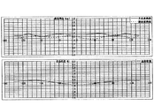
表−1に本実施形態の光学パラメータを示す。図3に本実施形態の光学特性を示す。
【0067】
【表1】
本実施形態の第1、第2のfθレンズ6a,6bは共に正のメニスカス形状より成り、また第1,第2のfθレンズ6a、6bのうち、少なくとも一面の副走査方向の曲率半径を、該レンズの有効部内において連続的、かつ光軸に対して主走査方向に非対称に変化させ、像面湾曲の非対称性とスポット径の変動を同時に補正している。
【0069】
本実施形態では、副走査曲率半径非対称面が一面で構成されているため、主走査方向の対称軸(fθレンズの光軸)を被走査面7の垂直二等分線に対してシフトかつチルトしている。これにより副走査曲率半径非対称面(副走査方向の曲率半径を光軸に対して主走査方向に沿って非対称に変化させた面)を追加することと同様の効果が得られ、該副走査曲率半径非対称面を一面のみで非対称性を補正することが可能であり、レンズ成形上有利になるという特徴を有する。
【0070】
尚、本実施形態では走査レンズ系6の光軸を主走査方向における被走査面の垂直二等分線と一致させている。
【0071】
本実施形態では走査レンズ系6の光軸方向における光偏向器5の偏向点5bから被走査面7までの距離をT、走査レンズ系6の光軸方向における該光偏向器5の偏向点5bから最も被走査面7側の第2のfθレンズ6bのレンズ面までの距離をS、走査レンズ系6の副走査断面内の光軸上の横倍率をβs(βs≦0)とするとき、
S/T≦0.3 ‥‥(1)
|βs|≦3 ‥‥(2)
なる条件を満たすように各要素を設定している。
【0072】
本実施形態では上記条件式(1)を満たすように
S/T=0.25
と各要素を配置し、これによりレンズバックを確保し、折り返しミラー8の配置自由度を高めると共に、走査レンズ系6のfθレンズの主走査方向の最大有効径Ymaxを小さくして、コンパクト化を達成している。
【0073】
ここでfθレンズの主走査方向の最大有効径Ymaxとは、図4に示すように、被走査面の走査開始位置又は走査終了位置に向かう光線が、fθレンズと交わる点の光軸との距離の最大値である。
【0074】
本実施形態ではfθレンズの主走査方向の最大有効径Ymaxを、
Ymax≦60mm ‥‥(3)
なる条件を満たすように設定している。
【0075】
副走査断面内の横倍率βsは走査レンズ系6の副走査方向の前側主平面をΔ、後側主平面をΔ'、第1,第2のfθレンズ6a、6bの肉厚を各々d1、d2、第1,第2のfθレンズ6a、6b間の距離(レンズ間隔)をUとするとき、
【0076】
【数5】
と近似できる。そのため上式(4)から副走査横倍率|βs|を低減し、ピッチムラを小さくするためには、
(a)走査レンズ系6の副走査方向の前側主平面及び後側主平面を被走査面7側に配置する、
(b)走査レンズ系6の2枚のfθレンズ6a、6b間の距離Uを小さくする、ことが必要である。
【0078】
そこで本実施形態では上記(a)を達成するために、
最も光偏向器5側の第1のfθレンズ6aの副走査方向の屈折力φ1、
最も被走査面7側の第2のfθレンズ6bの副走査方向の屈折力φ2、
とするとき、
副走査方向の曲率半径を上記表−1の如く設定し、即ち
φ1=−0.022<0
φ2=0.039>0
とし、走査レンズ系6の副走査方向の後側主平面を被走査面7に近づけるよう配置することにより、副走査横倍率|βs|を
|βs|=2.89
として上記条件式(2)を満たしている。
【0079】
また上記(b)を達成するために、第1、第2のfθレンズ6a、6bのレンズ間の距離をU、光偏向器5の偏向点5bから最も被走査面7側の第2のfθレンズ6bのレンズ面までの距離をSとするとき、
U/S≦0.6 ‥‥(5)
なる条件を満たすように各要素を設定している。本実施形態では上記条件式(5)を満たすように、
U/S=0.18
と各要素を配置し、これにより副走査横倍率|βs|を低減させて、ピッチムラを小さくしている。
【0080】
また第1、第2のfθレンズ6a、6b間の距離Uを短縮し、最も光偏向器5側の第1のfθレンズ6aを光偏向器5から遠ざけることにより、該光偏向器5の回転に伴い発生する発熱や振動がレンズ等の光学素子に与える影響(例えば、ピント変動)を軽減する効果をも有する。
【0081】
副走査横倍率|βs|をさらに低減させるためには最も被走査面7側のfθレンズの光偏向器5側のレンズ面が正の屈折力を有するレンズ面であることが望ましい。本実施形態では第2のfθレンズ6bの副走査断面内の入射面R3を正の屈折力のレンズ面にしている。
【0082】
また高精細な画像形成装置やカラー出力可能な画像形成装置に用いられる光走査装置においては、被走査面上でのスポット径を70μm以下に抑えることが望ましい。そこで本実施形態では副走査断面内において被走査面7上での有効F値(有効Fナンバー)をFSnoとするとき、有効走査域全域において、
FSno≦65 ‥‥(6)
なる条件を満たすように各要素を設定している。
【0083】
また主走査断面内において、被走査面7上での有効F値をFMnoとするとき、有効走査域全域において、
FMno≦55 ‥‥(7)
なる条件を満たすように各要素を設定している。
【0084】
また本実施形態では第3の光学系6を構成する1つの光学素子としての折り返しミラー8の位置を次の如く設定している。
【0085】
即ち、光偏向器5の偏向点5bから折り返しミラー8までの光軸上の距離をP、該折り返しミラー8から被走査面7までの距離をQとするとき、
1.5≦Q/P ‥‥(8)
なる条件を満たすように各要素を設定している。
【0086】
一般的に光走査装置は図2に示すように光路を折り返しミラー等で折り返し、本体(画像形成装置)に配置されるため、光走査装置を小型化するためには光偏向器の偏向点から折り返しミラーまでの距離を短くする必要がある(距離Pを小さくする必要がある。)。また光走査装置が本体に配置されるときは他の部材、例えば現像器等を排泄するスペースを確保する必要があり、ミラーバック(Q)を長くする必要がある。また折り返しミラーで折り返す角度も鈍角である方が、よりスペースを確保しやすく、また他部材との距離を確保でき、光走査装置が昇温の影響を受けづらい等のメリットがある。
【0087】
本実施形態では上記条件式(8)を満たすように、
P=53、Q=120、Q/P=2.26
と各要素を配置し、これにより前述した効果を得ている。
【0088】
このように本実施形態では上述の如く各条件式を満足させ、最も被走査面側の第2のfθレンズ6bを光偏向器5側に近づけることにより、折り返しミラー8を配置する際の自由度を高め、さらに第1、第2のfθレンズ6a、6bの副走査方向の曲率半径を適切に設定することにより、副走査横倍率の絶対値を低下させ、ピッチムラの少ない高精細な光走査装置を得ている。
【0089】
尚、本実施形態では上記の条件式(1),(5)のうち少なくとも一方を満たし、かつ条件式(2)を満たせば所望の効果は得られる。
【0090】
また本実施形態では光源手段1としてモノリシックなマルチビーム光源を用いたが、これに限らず、例えば異なる複数の光源から出射した光束をプリズム等で合成した光源手段を用いてもよく、もちろん光源手段を単一の光源より構成しても良い。
【0091】
また本実施形態では走査レンズ系6を2枚のレンズ6a,6bより構成したが、これに限らず、例えば単一、もしくは3枚以上で構成してもよく、さらにfθミラーや回折光学素子等の光学素子を用いても全く同様の効果を得ることができる。
【0092】
尚、走査レンズ系6を1枚のレンズより構成した場合は、上記条件式(1),(2)を満たせば所望の効果は得られる。
【0093】
また本実施形態においては集光レンズ2やシリンドリカルレンズ3等を省略し、光源手段1から出射した光束を開口絞り4を介して直接光偏向器5の偏向面5aに導光してもよい。
【0094】
[実施形態2]
図5は本発明の実施形態2の主走査方向の要部断面図(主走査断面図)である。同図において前記図1に示した要素と同一要素には同符番を付している。
【0095】
表―2に本実施形態の光学パラメータを示す。図6に本実施形態の光学特性を示す。
【0096】
【表2】
本実施形態において前述の実施形態1と異なる点は走査レンズ系16を構成する第1、第2のfθレンズ16a,16bのレンズ形状を異ならせて形成し、かつ上記の各条件式を満たすように各要素を設定したことであり、その他の構成及び光学的作用は実施形態1と略同様であり、これにより同様な効果を得ている。
【0098】
即ち、本実施形態の第1、第2のfθレンズ16a,16bは共にプラスチックレンズで作製されており、主走査断面内の形状がサグ(偏向面の出入り)による被走査面7の像面湾曲、fθ特性の非対称性を良好に補正するために、走査開始側と終了側で光軸(被走査面の垂直二等分線)に対して非対称に形成されている。
【0099】
また副走査方向の曲率半径は少なくとも2面がレンズの有効部内において連続的に変化しており、これにより像面湾曲、スポット径の変動を補正している。
【0100】
また非対称なサグにより像面湾曲、スポット径の変動が光軸に対して非対称に変化するのを良好に補正するために、走査レンズ系16は副走査方向の曲率半径が光軸に対して主走査方向に沿って非対称に変化する面(副走査曲率半径非対称面)を少なくとも1面有している。
【0101】
さらに本実施形態では前記条件式(1)を満足するように、
S/T=0.26
と各要素を配置し、これによりレンズバックを確保し、折り返しミラー8の配置自由度を高めると共に、走査レンズ系16のfθレンズの主走査方向の最大有効径Ymaxを小さくして、コンパクト化を達成している。
【0102】
また本実施形態では副走査方向の曲率半径を上記表-2の如く設定し、即ち
φ1=−0.014<0
φ2=0.025>0
とし、走査レンズ系16の副走査方向の後側主平面を被走査面7に近づけるよう配置することにより、副走査横倍率|βs|を
|βs|=2.69
として上記条件式(2)を満たしている。
【0103】
また本実施形態では前記条件式(5)を満たすように、
U/S=0.34
と各要素を配置し、これにより副走査横倍率|βs|を低減させて、ピッチムラを小さくしている。
【0104】
さらに本実施形態では前記条件式(8)を満たすように、
P=80、Q=131.35、Q/P=1.64
と各要素を配置し、これにより前述した効果を得ている。
【0105】
本実施形態は副走査曲率半径非対称面(子線非対称面)が2面で構成されており、レンズ作製上有利であると共に第2のfθレンズ16bの主走査方向の対称軸を被走査面7の垂直二等分線に対して対称に構成しているため、取り付け誤差による性能の劣化を低減できるという特徴を有する。
【0106】
このように本実施形態では上述の如く各条件式を満足させ、最も被走査面7側の第2のfθレンズ16bを光偏向器5側に近づけることにより、折り返しミラー8を配置する際の自由度を高め、さらに第1、第2のfθレンズ16a、16bの副走査方向の曲率半径を適切に設定することにより、副走査横倍率の絶対値を低下させ、ピッチムラの少ない高精細な光走査装置を得ている。
【0107】
[実施形態3]
図7は本発明の実施形態3の主走査方向の要部断面図(主走査断面図)である。同図において前記図1に示した要素と同一要素には同符番を付している。
【0108】
表―3に本実施形態の光学パラメータを示す。図8に本実施形態の光学特性を示す。
【0109】
【表3】
本実施形態において前述の実施形態1、2と異なる点は走査レンズ系26の少なくとも一面を主走査断面内又は/及び副走査断面内において回折作用を有する回折面より構成し、かつ上記の各条件式を満たすように各要素を設定したことであり、その他の構成及び光学的作用は実施形態1と略同様であり、これにより同様な効果を得ている。
【0111】
即ち、26は第3の光学系としての走査レンズ系であり、第1、第2の2枚の走査レンズ26,26bを有しており、第1の走査レンズ26aは両レンズ面共に屈折面で、非球面形状のトーリック面より成り、第2の走査レンズ26bは光偏向器5側が屈折面でトーリック面より成り、被走査面7側が主走査断面内又は/及び副走査断面内において回折作用を有する回折面より成っている。
【0112】
本実施形態の回折面は、光軸をX軸、主走査断面内において光軸と直交する方向をY軸、副走査断面内で光軸と直交する方向をZ軸とし、以下の連続関数で表せる。
【0113】
【数6】
(φは位相関数、λは波長、mは回折次数、本実施形態ではm=1を使用)
本実施形態の第1、第2のfθレンズ26,26bは共にプラスチックレンズで作製されており、成形上有利なように主走査断面内の形状が走査開始側と終了側で光軸に対して対称に構成されている。
【0115】
また副走査方向の曲率半径は少なくとも2面がレンズの有効部内において連続的に変化しており、これにより像面湾曲、スポット径の変動を補正している。
【0116】
また本実施形態では回折面の位相関数を走査開始側と走査終了側で光軸に対して非対称に変化させることで、像面湾曲、スポット径の変動が光軸に対して非対称性に変化するのを補正している。
【0117】
さらに本実施形態では前記条件式(1)を満たすように、
S/T=0.30
と各要素を配置し、これによりレンズバックを確保し、折り返しミラー8の配置自由度を高めると共に、走査レンズ系26のfθレンズの主走査方向の最大有効径Ymaxを小さくして、コンパクト化を達成している。
【0118】
また本実施形態では副走査方向の曲率半径を上記表-3の如く設定し、即ち
φ1=−0.006<0
φ2= 0.030>0
とし、走査レンズ系26の副走査方向の後側主平面を被走査面に近づけるよう配置することにより、副走査横倍率|βs|を
|βs|=2.61
として上記条件式(2)を満たしている。
【0119】
また本実施形態では前記条件式(5)を満足するように、
U/S=0.51
と各要素を配置し、これにより副走査横倍率|βs|を低減させて、ピッチムラを小さくしている。
【0120】
さらに本実施形態では前記条件式(8)を満たすように、
P=55.5、Q=104.0、Q/P=1.87
と各要素を配置し、これにより前述した効果を得ている。
【0121】
このように本実施形態では上述の如く各条件式を満足させ、最も被走査面7側の第2のfθレンズ26bを光偏向器5側に近づけることにより、折り返しミラー8を配置する際の自由度を高め、さらに第1、第2のfθレンズ26a、26bの副走査方向の曲率半径を適切に設定することにより、副走査横倍率の絶対値を低下させ、かつ回折光学素子を用いることにより、環境変化による光学性能の劣化の少ない高性能な光走査装置を得ることが可能である。
【0122】
[画像形成装置]
図9は、前述した実施形態1、2又は3の光走査装置を用いた画像形成装置(電子写真プリンタ)の実施形態を示す副走査断面内における要部断面図である。
【0123】
図9において、符号104は画像形成装置を示す。この画像形成装置104には、パーソナルコンピュータ等の外部機器117からコードデータDcが入力する。このコードデータDcは、装置内のプリンタコントローラ111によって、画像データ(ドットデータ)Diに変換される。この画像データDiは、各実施形態1、2、3で示した構成を有する光走査ユニット100に入力される。そして、この光走査ユニット(光走査装置)100からは、画像データDiに応じて変調された光ビーム(光束)103が射出され、この光ビーム103によって感光ドラム101の感光面が主走査方向に走査される。
【0124】
静電潜像担持体(感光体)たる感光ドラム101は、モータ115によって時計廻りに回転させられる。そして、この回転に伴って、感光ドラム101の感光面が光ビーム103に対して、主走査方向と直交する副走査方向に移動する。感光ドラム101の上方には、感光ドラム101の表面を一様に帯電せしめる帯電ローラ102が表面に当接するように設けられている。そして、帯電ローラ102によって帯電された感光ドラム101の表面に、前記光走査ユニット100によって走査される光ビーム103が照射されるようになっている。
【0125】
先に説明したように、光ビーム103は、画像データDiに基づいて変調されており、この光ビーム103を照射することによって感光ドラム101の表面に静電潜像を形成せしめる。この静電潜像は、上記光ビーム103の照射位置よりもさらに感光ドラム101の回転断面内における下流側で感光ドラム101に当接するように配設された現像器107によってトナー像として現像される。
【0126】
現像器107によって現像されたトナー像は、感光ドラム101の下方で、感光ドラム101に対向するように配設された転写ローラ(転写器)108によって被転写材たる用紙112上に転写される。用紙112は感光ドラム101の前方(図9において右側)の用紙カセット109内に収納されているが、手差しでも給紙が可能である。用紙カセット109端部には、給紙ローラ110が配設されており、用紙カセット109内の用紙112を搬送路へ送り込む。
【0127】
以上のようにして、未定着トナー像を転写された用紙112はさらに感光ドラム101後方(図9において左側)の定着器へと搬送される。定着器は内部に定着ヒータ(図示せず)を有する定着ローラ113とこの定着ローラ113に圧接するように配設された加圧ローラ114とで構成されており、転写部から撒送されてきた用紙112を定着ローラ113と加圧ローラ114の圧接部にて加圧しながら加熱することにより用紙112上の未定着トナー像を定着せしめる。更に定着ローラ113の後方には排紙ローラ116が配設されており、定着された用紙112を画像形成装置の外に排出せしめる。
【0128】
図9においては図示していないが、プリントコントローラ111は、先に説明したデータの変換だけでなく、モータ115を始め画像形成装置内の各部や、光走査ユニット100内のポリゴンモータなどの制御を行う。
【0129】
【発明の効果】
本発明によれば前述の如く第3の光学系(走査レンズ系)を構成する光学素子のうち最も被走査面側の光学素子を光偏向器側に近づけることにより、折り返しミラーを配置する際の自由度を高めることができ、また光学素子の副走査方向の曲率半径を適切に設定することにより、副走査横倍率の絶対値を低下させ、ピッチムラの少ない高性能でコンパクトな光走査装置及びそれを用いた画像形成装置を達成することができる。
【図面の簡単な説明】
【図1】 本発明の実施形態1の主走査断面図
【図2】 本発明の実施形態1の副走査断面図
【図3】 本発明の実施形態1の光学特性を示す図
【図4】 本発明の実施形態1のYmaxを示す図
【図5】 本発明の実施形態2の主走査断面図
【図6】 本発明の実施形態2の光学特性を示す図
【図7】 本発明の実施形態3の主走査断面図
【図8】 本発明の実施形態3の光学特性を示す図
【図9】 本発明の光走査装置を用いた画像形成装置(電子写真プリンタ)の構成例を示す副走査断面図
【図10】 従来の光走査装置の主走査断面図
【図11】 従来の光走査装置の副走査断面図
【符号の説明】
1 光源手段(半導体レーザ)
2 コリメーターレンズ
3 絞り
4 シリンドリカルレンズ
5 偏向手段(ポリゴンミラー)
6,16,26 走査レンズ系(fθレンズ系)
7 被走査面
8 折り返しミラー
100 光走査装置
101 感光ドラム
102 帯電ローラ
103 光ビーム
104 画像形成装置
107 現像装置
108 転写ローラ
109 用紙カセット
110 給紙ローラ
111 プリンタコントローラ
112 転写材(用紙)
113 定着ローラ
114 加圧ローラ
115 モータ
116 排紙ローラ
117 外部機器[0001]
BACKGROUND OF THE INVENTION
The present invention relates to an optical scanning device and an image forming apparatus using the same, and in particular, increases the degree of freedom in disposing a folding mirror, reduces the absolute value of lateral magnification in the sub-scanning direction, and causes pitch unevenness (scanning lines due to surface tilting). It is suitable for an image forming apparatus such as a laser printer, a digital copying machine, or a multifunction printer (multifunctional printer).
[0002]
[Prior art]
Conventionally, in an optical scanning device used for a laser beam printer, a digital copying machine, a multifunction printer, etc., a light beam (light beam) emitted from a light source according to an image signal is periodically generated by an optical deflector such as a rotating polygon mirror. Using a scanning lens having an fθ characteristic, spots are formed while scanning the surface of the photosensitive drum, which is the surface to be scanned, at a substantially constant speed. As a result, image information is recorded on the surface of the photosensitive drum as a recording medium.
[0003]
FIG. 10 is a sectional view (main scanning sectional view) of the main part in the main scanning direction of the conventional optical scanning device, and FIG. 11 is a sectional view (sub scanning sectional view) of the relevant part in the sub scanning direction of the conventional optical scanning apparatus.
[0004]
10 and 11, the divergent light beam emitted from the light source means 91 is changed into a substantially parallel light beam or a convergent light beam by a condenser lens (collimator lens) 92, and the light beam is limited by a
[0005]
In this type of optical scanning device, in order to record a high-definition image,
(Ar 1) the field curvature is well corrected over the entire surface to be scanned;
(Ar 2) The spot diameter and spot shape on the scanned surface are good,
(Ar 3) It has a tilt correction function for correcting so that the positional deviation of the scanning line does not occur even when the deflecting surface of the optical deflector falls.
(Ar 4) Distortion is corrected well,
Etc. are necessary.
[0006]
Furthermore, in recent years, with the miniaturization of image forming apparatuses, the optical scanning apparatus has to be miniaturized, and the scanning lens is also required to have a compact lens shape.
[0007]
[Problems to be solved by the invention]
In order to make the scanning lens system compact, it is necessary to shorten the focal length of the scanning lens system, that is, to shorten the distance from the deflection point of the optical deflector to the surface to be scanned. When the distance is shortened, the distance from the lens surface of the scanning lens closest to the scanning surface side to the scanning surface (lens back) is shortened, and the optical path between the scanning lens surface closest to the scanning surface side and the scanning surface is reduced. When a folding mirror or the like is disposed on the screen, the degree of freedom is reduced.
[0008]
Moreover, even if the lens back can be secured to some extent, the lateral magnification in the sub-scanning direction (sub-scanning magnification) becomes high, and the deterioration of the scanning line (pitch unevenness) due to the surface tilt increases, and a high-definition image forming apparatus or There is a problem that it cannot be applied to a color image forming apparatus capable of color output.
[0009]
Thus, in recent years, it has been difficult to obtain a desired optical performance by securing a lens back and reducing a sub-scanning magnification while a compact optical scanning device is required.
[0010]
The present invention is a compact, high-quality optical scanning device with a long lens back that can secure a lens back, reduce pitch unevenness, and can satisfactorily correct variations in curvature of field, distortion, and beam diameter due to image height. And an image forming apparatus using the same.
[0011]
[Means for Solving the Problems]
The optical scanning device according to
The third optical system includes a first scanning optical element and a second scanning optical element in order from the deflecting unit,
In the optical path between the second scanning optical element and the scanned surface Plane mirror Is provided Plane mirror In the sub-scan section, the angle at which the incident light beam is folded is an obtuse angle,
In the optical axis direction of the third optical system The surface to be scanned from the deflection point of the deflection means Distance to T In the optical axis direction of the third optical system The exit surface of the second scanning optical element from the deflection point of the deflection means Distance to S in the sub-scan section of the third optical system On the optical axis The lateral magnification is βs (βs ≦ 0), and the deflection point of the deflection unit in the optical axis direction of the third optical system is Plane mirror P is the distance to the optical axis direction of the third optical system. Plane mirror Q from the scanning surface to the surface to be scanned in the optical axis direction of the third optical system Distance from the first scanning optical element to the second scanning optical element U, of the first scanning optical element On the optical axis The refractive power in the sub-scanning direction is φ1, and the second scanning optical element On the optical axis When the refractive power in the sub-scanning direction is φ2,
S / T ≦ 0.3,
1.5 ≦ Q / P,
U / S ≦ 0.6,
φ1 <0, φ2> 0,
| Βs | ≦ 3
It is characterized by satisfying the following condition.
[0012]
A second aspect of the present invention is characterized in that, in the first aspect of the invention, the light source means has a plurality of light emitting portions.
[0013]
In the invention of
FSno ≦ 65
It is characterized by satisfying the following condition.
[0014]
The invention of
FMNO ≦ 55
It is characterized by satisfying the following condition.
[0015]
An image forming apparatus according to a fifth aspect of the present invention comprises 4 An electrostatic latent image formed on the photoconductor by the optical scanning device according to any one of the above, a photoconductor arranged on the surface to be scanned, and a light beam scanned by the optical scanning device. The image forming apparatus includes a developing device that develops the toner image, a transfer unit that transfers the developed toner image onto the transfer material, and a fixing device that fixes the transferred toner image onto the transfer material.
[0016]
An image forming apparatus according to a sixth aspect of the present invention is the first aspect. 4 The optical scanning device according to any one of the above, and a printer controller that converts code data input from an external device into an image signal and inputs the image signal to the optical scanning device.
[0034]
DETAILED DESCRIPTION OF THE INVENTION
[Embodiment 1]
FIG. 1 is a sectional view (main scanning sectional view) of the main part in the main scanning direction according to
[0035]
In this specification, the surface formed by the optical axis of the scanning lens system and the light beam deflected by the optical deflector is the main scanning section, and the surface including the optical axis of the scanning lens system and orthogonal to the main scanning section is sub-scanned. It is defined as a cross section.
[0036]
1 and 2,
[0037]
An optical deflector 5 as a deflecting means is composed of, for example, a four-sided polygon mirror (rotating polygon mirror), and is rotated at a constant speed in the direction of arrow A in the figure by a driving means (not shown) such as a motor. ing.
[0038]
[0039]
In the present embodiment, of the two
[0040]
[0041]
In the present embodiment, a plurality of divergent light beams emitted from the multi-beam
[0042]
In the present embodiment, the shapes of the first and
[0043]
For example, the intersection point between the first and
The surface shape of the
[0044]
[Expression 1]
The surface shape of the
[0046]
[Expression 2]
It is represented by
[0048]
Where R is the radius of curvature, K, B Four , B 6 , B 8 , B Ten Is the aspheric coefficient. The coefficient suffix s represents the scanning start side, and the suffix e represents the scanning end side.
[0049]
In the sub-scan section, the curvature radius in the sub-scan direction of at least two surfaces of the first and
[0050]
As shown in FIG. 2, the shape in the sub-scan section is the X axis on the scan start side and the scan end side with respect to the optical axis, the Y axis is the direction perpendicular to the optical axis in the main scan section, and the sub scan. When the direction perpendicular to the optical axis in the cross section is taken as the Z axis, it can be expressed by the following continuous function.
[0051]
The surface shape of the
[0052]
[Equation 3]
The surface shape of the
[0054]
[Expression 4]
It is represented by
[0056]
Where r is the radius of curvature in the sub-scanning direction, and D 2 , D Four , D 6 , D 8 , D Ten Is a coefficient
The coefficient suffix s represents the scanning start side, and e represents the scanning end side.
[0057]
The curvature radius in the sub-scanning direction is a curvature radius in a cross section perpendicular to the shape (bus line) in the main scanning direction.
[0058]
In the present embodiment, the first fθ is corrected in order to correct focus correction (field curvature correction) in the sub-scanning direction and uniformity of magnification in the sub-scanning direction in the scanning lens system 6 (variation due to image height of the spot diameter). The curvature radii in the sub-scanning direction of both lens surfaces R1, R2 of the
[0059]
Next, means and effects for achieving the object of the present invention will be described.
[0060]
The light source means 1 of the present embodiment is composed of a monolithic multi-beam light source having a plurality of light emitting portions on the same chip as described above, and the first and
[0061]
Further, at least two surfaces of the radius of curvature in the sub-scanning direction continuously change within the effective portion of the lens, thereby correcting field curvature, wavefront aberration, and spot diameter variation.
[0062]
In the present embodiment, the light beam emitted from the light source means 1 is incident on the
[0063]
In this embodiment, in order to make the entire apparatus compact, a folding mirror 8 that satisfies conditional expression (8) described later is disposed in the optical path between the
[0064]
Further, in this embodiment, the asymmetry due to the sag of the wavefront aberration is satisfactorily corrected by forming the sub-scanning curvature radius asymmetric surface on the
[0065]
On the other hand, unless the curvature radius in the sub-scanning direction is changed by at least two or more surfaces, both the curvature of field and the variation of the spot diameter cannot be corrected at the same time.
[0066]
Table 1 shows the optical parameters of the present embodiment. FIG. 3 shows the optical characteristics of this embodiment.
[0067]
[Table 1]
The first and
[0069]
In this embodiment, since the sub-scanning curvature asymmetric surface is composed of one surface, the axis of symmetry in the main scanning direction (the optical axis of the fθ lens) is shifted and tilted with respect to the perpendicular bisector of the surface to be scanned 7. is doing. Thus, an effect similar to that of adding a sub-scanning curvature radius asymmetric surface (a surface in which the curvature radius in the sub-scanning direction is changed asymmetrically with respect to the optical axis along the main scanning direction) can be obtained. It is possible to correct asymmetry with only one radial asymmetric surface, which is advantageous in terms of lens molding.
[0070]
In the present embodiment, the optical axis of the
[0071]
In this embodiment In the optical axis direction of the
S / T ≦ 0.3 (1)
| Βs | ≦ 3 (2)
Each element is set to satisfy the following condition.
[0072]
In the present embodiment, the conditional expression (1) is satisfied.
S / T = 0.25
These elements are arranged, thereby securing a lens back, increasing the degree of freedom of arrangement of the folding mirror 8, and reducing the maximum effective diameter Ymax in the main scanning direction of the fθ lens of the
[0073]
Here, the maximum effective diameter Ymax of the fθ lens in the main scanning direction is the distance from the optical axis at the point where the light beam traveling toward the scanning start position or scanning end position of the surface to be scanned intersects with the fθ lens, as shown in FIG. Is the maximum value.
[0074]
In this embodiment, the maximum effective diameter Ymax of the fθ lens in the main scanning direction is
Ymax ≦ 60mm (3)
Is set to satisfy the following condition.
[0075]
The lateral magnification βs in the sub-scanning section is Δ for the front main plane in the sub-scanning direction of the
[0076]
[Equation 5]
Can be approximated. Therefore, in order to reduce the sub-scanning lateral magnification | βs | from the above equation (4) and reduce the pitch unevenness,
(a) The front main plane and the rear main plane in the sub-scanning direction of the
(b) It is necessary to reduce the distance U between the two
[0078]
Therefore, in the present embodiment, in order to achieve the above (a),
Refracting power φ1 in the sub-scanning direction of the
Refracting power φ2 in the sub-scanning direction of the
And when
The curvature radius in the sub-scanning direction is set as shown in Table 1 above.
φ1 = −0.022 <0
φ2 = 0.039> 0
By arranging the rear main plane of the
| βs | = 2.89
The above conditional expression (2) is satisfied.
[0079]
In order to achieve the above (b), the distance between the lenses of the first and
U / S ≦ 0.6 (5)
Each element is set to satisfy the following condition. In the present embodiment, so as to satisfy the conditional expression (5),
U / S = 0.18
Each element is arranged, thereby reducing the sub-scanning lateral magnification | βs | and reducing the pitch unevenness.
[0080]
Further, by shortening the distance U between the first and
[0081]
In order to further reduce the sub-scanning lateral magnification | βs |, it is desirable that the lens surface on the optical deflector 5 side of the fθ lens closest to the scanned
[0082]
Further, in an optical scanning device used in a high-definition image forming apparatus or an image forming apparatus capable of color output, it is desirable to suppress the spot diameter on the surface to be scanned to 70 μm or less. Therefore, in this embodiment, when the effective F value (effective F number) on the surface to be scanned 7 is FSno in the sub-scan section,
FSno ≦ 65 (6)
Each element is set to satisfy the following condition.
[0083]
In the main scanning section, when the effective F value on the scanned
FMNO ≦ 55 (7)
Each element is set to satisfy the following condition.
[0084]
In this embodiment, the position of the folding mirror 8 as one optical element constituting the third
[0085]
That is, when the distance on the optical axis from the
1.5 ≦ Q / P (8)
Each element is set to satisfy the following condition.
[0086]
In general, the optical scanning device is configured by folding the optical path with a folding mirror or the like as shown in FIG. 2 and arranged in the main body (image forming apparatus). Therefore, in order to reduce the size of the optical scanning device, the deflection point of the optical deflector is used. It is necessary to shorten the distance to the folding mirror (the distance P needs to be reduced). Further, when the optical scanning device is disposed in the main body, it is necessary to secure a space for excreting other members, such as a developing device, and it is necessary to lengthen the mirror back (Q). Further, when the angle turned back by the turning mirror is an obtuse angle, it is easier to secure a space, and it is possible to secure a distance from other members, and there is an advantage that the optical scanning device is not easily affected by the temperature rise.
[0087]
In the present embodiment, so as to satisfy the conditional expression (8),
P = 53, Q = 120, Q / P = 2.26
Each element is arranged to obtain the effect described above.
[0088]
As described above, in this embodiment, each conditional expression is satisfied as described above, and the degree of freedom in disposing the folding mirror 8 by bringing the
[0089]
In the present embodiment, a desired effect can be obtained if at least one of the conditional expressions (1) and (5) is satisfied and the conditional expression (2) is satisfied.
[0090]
In the present embodiment, a monolithic multi-beam light source is used as the
[0091]
In this embodiment, the
[0092]
When the
[0093]
In the present embodiment, the condensing
[0094]
[Embodiment 2]
FIG. 5 is a sectional view (main scanning sectional view) of the main part in the main scanning direction according to the second embodiment of the present invention. In the figure, the same elements as those shown in FIG.
[0095]
Table-2 shows the optical parameters of this embodiment. FIG. 6 shows the optical characteristics of this embodiment.
[0096]
[Table 2]
In this embodiment, the difference from the first embodiment is that the first and
[0098]
That is, the first and
[0099]
Further, at least two surfaces of the radius of curvature in the sub-scanning direction continuously change in the effective portion of the lens, thereby correcting field curvature and spot diameter variation.
[0100]
In addition, the
[0101]
Furthermore, in this embodiment, so as to satisfy the conditional expression (1),
S / T = 0.26
These elements are arranged, thereby securing a lens back, increasing the degree of freedom of arrangement of the folding mirror 8, and reducing the maximum effective diameter Ymax in the main scanning direction of the fθ lens of the
[0102]
In this embodiment, the radius of curvature in the sub-scanning direction is set as shown in Table 2 above.
φ1 = −0.014 <0
φ2 = 0.025> 0
By arranging the rear main plane of the
| βs | = 2.69
The above conditional expression (2) is satisfied.
[0103]
In this embodiment, so as to satisfy the conditional expression (5),
U / S = 0.34
Each element is arranged, thereby reducing the sub-scanning lateral magnification | βs | and reducing the pitch unevenness.
[0104]
Furthermore, in this embodiment, so as to satisfy the conditional expression (8),
P = 80, Q = 131.35, Q / P = 1.64
Each element is arranged to obtain the effect described above.
[0105]
In the present embodiment, the sub-scanning radius-of-curvature asymmetric surface (sub-wire asymmetric surface) is composed of two surfaces, which is advantageous in terms of lens fabrication, and the axis of symmetry of the
[0106]
As described above, in the present embodiment, each conditional expression is satisfied as described above, and the
[0107]
[Embodiment 3]
FIG. 7 is a sectional view (main scanning sectional view) of the main part in the main scanning direction of
[0108]
Table 3 shows the optical parameters of this embodiment. FIG. 8 shows the optical characteristics of this embodiment.
[0109]
[Table 3]
The present embodiment is different from the first and second embodiments described above in that at least one surface of the
[0111]
That is,
[0112]
The diffraction surface of the present embodiment has an optical axis as an X axis, a direction perpendicular to the optical axis in the main scanning section as a Y axis, and a direction perpendicular to the optical axis in the sub-scanning section as a Z axis. I can express.
[0113]
[Formula 6]
(φ is a phase function, λ is a wavelength, m is a diffraction order, and m = 1 is used in this embodiment)
The first and
[0115]
Further, at least two surfaces of the radius of curvature in the sub-scanning direction continuously change in the effective portion of the lens, thereby correcting field curvature and spot diameter variation.
[0116]
Further, in this embodiment, by changing the phase function of the diffractive surface asymmetrically with respect to the optical axis on the scanning start side and the scanning end side, the curvature of field and the variation in spot diameter change asymmetrically with respect to the optical axis. Is corrected.
[0117]
Furthermore, in this embodiment, so as to satisfy the conditional expression (1),
S / T = 0.30
These elements are arranged, thereby securing a lens back, increasing the degree of freedom of arrangement of the folding mirror 8, and reducing the maximum effective diameter Ymax of the fθ lens of the
[0118]
In this embodiment, the radius of curvature in the sub-scanning direction is set as shown in Table 3 above.
φ1 = −0.006 <0
φ2 = 0.030> 0
By arranging the rear main plane of the
| βs | = 2.61
The above conditional expression (2) is satisfied.
[0119]
In this embodiment, so as to satisfy the conditional expression (5),
U / S = 0.51
Each element is arranged, thereby reducing the sub-scanning lateral magnification | βs | and reducing the pitch unevenness.
[0120]
Furthermore, in this embodiment, so as to satisfy the conditional expression (8),
P = 55.5, Q = 104.0, Q / P = 1.87
Each element is arranged to obtain the effect described above.
[0121]
As described above, in the present embodiment, each conditional expression is satisfied as described above, and the
[0122]
[Image forming apparatus]
FIG. 9 is a cross-sectional view of an essential part in a sub-scanning cross section showing an embodiment of an image forming apparatus (electrophotographic printer) using the optical scanning device of the first, second or third embodiment described above.
[0123]
In FIG. 9,
[0124]
The
[0125]
As described above, the
[0126]
The toner image developed by the developing
[0127]
As described above, the
[0128]
Although not shown in FIG. 9, the
[0129]
【The invention's effect】
According to the present invention, as described above, the optical element constituting the third optical system (scanning lens system) is moved closer to the optical deflector side by bringing the optical element closest to the scanned surface closer to the optical deflector side. It is possible to increase the degree of freedom, and by appropriately setting the radius of curvature of the optical element in the sub-scanning direction, the absolute value of the sub-scanning lateral magnification is reduced, and a high-performance and compact optical scanning device with little pitch unevenness and the same An image forming apparatus using can be achieved.
[Brief description of the drawings]
FIG. 1 is a main scanning sectional view of
FIG. 2 is a sub-scan sectional view of
FIG. 3 is a diagram showing optical characteristics of
FIG. 4 is a diagram showing Ymax according to the first embodiment of the present invention.
FIG. 5 is a main scanning sectional view of
FIG. 6 is a diagram showing optical characteristics of
FIG. 7 is a main scanning sectional view of
FIG. 8 is a diagram showing optical characteristics of
FIG. 9 is a sub-scanning sectional view showing a configuration example of an image forming apparatus (electrophotographic printer) using the optical scanning device of the present invention.
FIG. 10 is a main scanning sectional view of a conventional optical scanning device.
FIG. 11 is a sub-scan sectional view of a conventional optical scanning device.
[Explanation of symbols]
1 Light source means (semiconductor laser)
2 Collimator lens
3 Aperture
4 Cylindrical lens
5 Deflection means (polygon mirror)
6, 16, 26 Scanning lens system (fθ lens system)
7 Scanned surface
8 Folding mirror
100 Optical scanning device
101 Photosensitive drum
102 Charging roller
103 Light beam
104 Image forming apparatus
107 Developing device
108 Transfer roller
109 Paper cassette
110 Paper feed roller
111 Printer controller
112 Transfer material (paper)
113 Fixing roller
114 Pressure roller
115 motor
116 Paper discharge roller
117 External equipment
Claims (6)
前記第3の光学系は、前記偏向手段から順に、第1の走査光学素子、第2の走査光学素子から構成され、
前記第2の走査光学素子と前記被走査面の間の光路内に平面ミラーが設けられ、前記平面ミラーは、副走査断面内において、入射した光束を折り返す角度が鈍角であり、
前記第3の光学系の光軸方向における前記偏向手段の偏向点から前記被走査面までの距離をT、前記第3の光学系の光軸方向における前記偏向手段の偏向点から前記第2の走査光学素子の出射面までの距離をS、前記第3の光学系の副走査断面内の光軸上の横倍率をβs(βs≦0)、前記第3の光学系の光軸方向における前記偏向手段の偏向点から前記平面ミラーまでの距離をP、前記第3の光学系の光軸方向における前記平面ミラーから前記被走査面までの距離をQ、前記第3の光学系の光軸方向における前記第1の走査光学素子から前記第2の走査光学素子までの距離をU、前記第1の走査光学素子の光軸上の副走査方向の屈折力をφ1、前記第2の走査光学素子の光軸上の副走査方向の屈折力をφ2、とするとき、
S/T≦0.3、
1.5≦Q/P、
U/S≦0.6、
φ1<0、φ2>0、
|βs|≦3
なる条件を満たすことを特徴とする光走査装置。Light source means, a first optical system that converts a light beam emitted from the light source means into another light beam, a deflecting means, and a light beam that has passed through the first optical system is scanned on the deflection surface of the deflecting means. An optical scanning device comprising: a second optical system that forms a line image that is long in the direction; and a third optical system that forms an image of the light beam deflected by the deflecting surface of the deflecting unit on the surface to be scanned. Because
The third optical system includes a first scanning optical element and a second scanning optical element in order from the deflecting unit,
Plane mirror provided in an optical path between the surface to be scanned and the second scanning optical element, said plane mirror, in the sub-scan section, the angle of folding the light beam incident is obtuse,
The distance from the deflection point of the deflection unit in the optical axis direction of the third optical system to the scanned surface is T, and the second point from the deflection point of the deflection unit in the optical axis direction of the third optical system . The distance to the exit surface of the scanning optical element is S, the lateral magnification on the optical axis in the sub-scan section of the third optical system is βs (βs ≦ 0), and the optical axis direction of the third optical system is the optical axis direction. The distance from the deflection point of the deflecting means to the plane mirror is P, the distance from the plane mirror to the scanned surface in the optical axis direction of the third optical system is Q, the optical axis direction of the third optical system The distance from the first scanning optical element to the second scanning optical element is U, the refractive power in the sub-scanning direction on the optical axis of the first scanning optical element is φ1, and the second scanning optical element When the refractive power in the sub-scanning direction on the optical axis is φ2,
S / T ≦ 0.3,
1.5 ≦ Q / P,
U / S ≦ 0.6,
φ1 <0, φ2> 0,
| Βs | ≦ 3
An optical scanning device characterized by satisfying the following condition.
FSno≦65
なる条件を満たすことを特徴とする請求項1又は2に記載の光走査装置。When the effective F value on the surface to be scanned is FSno in the sub-scanning cross section, in the entire effective scanning area,
FSno ≦ 65
The optical scanning device according to claim 1 , wherein the following condition is satisfied.
FMno≦55
なる条件を満たすことを特徴とする請求項1乃至3の何れか1項に記載の光走査装置。In the main scanning section, when the effective F value on the surface to be scanned is FMNO, in the entire effective scanning area,
FMNO ≦ 55
The optical scanning device according to any one of claims 1 to 3, wherein the condition is satisfied to become.
Priority Applications (1)
| Application Number | Priority Date | Filing Date | Title |
|---|---|---|---|
| JP2001356257A JP4343466B2 (en) | 2001-11-21 | 2001-11-21 | Optical scanning device and image forming apparatus using the same |
Applications Claiming Priority (1)
| Application Number | Priority Date | Filing Date | Title |
|---|---|---|---|
| JP2001356257A JP4343466B2 (en) | 2001-11-21 | 2001-11-21 | Optical scanning device and image forming apparatus using the same |
Publications (3)
| Publication Number | Publication Date |
|---|---|
| JP2003156703A JP2003156703A (en) | 2003-05-30 |
| JP2003156703A5 JP2003156703A5 (en) | 2005-07-07 |
| JP4343466B2 true JP4343466B2 (en) | 2009-10-14 |
Family
ID=19167811
Family Applications (1)
| Application Number | Title | Priority Date | Filing Date |
|---|---|---|---|
| JP2001356257A Expired - Fee Related JP4343466B2 (en) | 2001-11-21 | 2001-11-21 | Optical scanning device and image forming apparatus using the same |
Country Status (1)
| Country | Link |
|---|---|
| JP (1) | JP4343466B2 (en) |
Families Citing this family (1)
| Publication number | Priority date | Publication date | Assignee | Title |
|---|---|---|---|---|
| JP4654072B2 (en) * | 2005-06-06 | 2011-03-16 | Hoya株式会社 | Scanning optical system |
-
2001
- 2001-11-21 JP JP2001356257A patent/JP4343466B2/en not_active Expired - Fee Related
Also Published As
| Publication number | Publication date |
|---|---|
| JP2003156703A (en) | 2003-05-30 |
Similar Documents
| Publication | Publication Date | Title |
|---|---|---|
| US20050206988A1 (en) | Optical scanning apparatus and image forming apparatus using the same | |
| JP3825995B2 (en) | Optical scanning device, multi-beam scanning device, and image forming apparatus using the same | |
| US7550712B2 (en) | Optical scanning system with reduced spherical aberration and image forming apparatus using the same | |
| JP4819392B2 (en) | Scanning optical device and image forming apparatus using the same | |
| KR101078513B1 (en) | Optical scanning apparatus and image forming apparatus using the same | |
| JP4684470B2 (en) | Optical scanning device and image forming apparatus using the same | |
| US7768542B2 (en) | Multi-beam optical scanning device and image forming apparatus using the same | |
| JP2004070107A (en) | Optical scanner and image forming apparatus using the same | |
| JP2001343602A (en) | Optical scanning optical system and image forming device using the same | |
| US7149019B2 (en) | Optical scanning system and image forming apparatus using the same | |
| JP4378081B2 (en) | Optical scanning device and image forming apparatus using the same | |
| JP2007156174A (en) | Optical scanner and image forming apparatus using the same | |
| JP2004070108A (en) | Optical scanner and image forming apparatus using the same | |
| JP4434547B2 (en) | Scanning optical device and image forming apparatus using the same | |
| US6980343B2 (en) | Optical scanning apparatus and image forming apparatus using the same | |
| JP4878158B2 (en) | Optical scanning device and image forming apparatus using the same | |
| JP2003156704A (en) | Optical scanner and image forming device using the same | |
| JP4343466B2 (en) | Optical scanning device and image forming apparatus using the same | |
| JP4612767B2 (en) | Scanning optical system and image forming apparatus using the scanning optical system | |
| JP4817526B2 (en) | Optical scanning device and image forming apparatus using the same | |
| JP5094221B2 (en) | Optical scanning device and image forming apparatus using the same | |
| JP4240777B2 (en) | Scanning optical device and image forming apparatus using the same | |
| JP4388053B2 (en) | Optical scanning device and image forming apparatus using the same | |
| JP4378416B2 (en) | Scanning optical device and image forming apparatus using the same | |
| JP4280748B2 (en) | Optical scanning device and image forming apparatus using the same |
Legal Events
| Date | Code | Title | Description |
|---|---|---|---|
| A521 | Written amendment |
Free format text: JAPANESE INTERMEDIATE CODE: A523 Effective date: 20041104 |
|
| A621 | Written request for application examination |
Free format text: JAPANESE INTERMEDIATE CODE: A621 Effective date: 20041104 |
|
| A977 | Report on retrieval |
Free format text: JAPANESE INTERMEDIATE CODE: A971007 Effective date: 20070727 |
|
| A131 | Notification of reasons for refusal |
Free format text: JAPANESE INTERMEDIATE CODE: A131 Effective date: 20070731 |
|
| A521 | Written amendment |
Free format text: JAPANESE INTERMEDIATE CODE: A523 Effective date: 20070925 |
|
| A131 | Notification of reasons for refusal |
Free format text: JAPANESE INTERMEDIATE CODE: A131 Effective date: 20090407 |
|
| A521 | Written amendment |
Free format text: JAPANESE INTERMEDIATE CODE: A523 Effective date: 20090603 |
|
| TRDD | Decision of grant or rejection written | ||
| A01 | Written decision to grant a patent or to grant a registration (utility model) |
Free format text: JAPANESE INTERMEDIATE CODE: A01 Effective date: 20090630 |
|
| A01 | Written decision to grant a patent or to grant a registration (utility model) |
Free format text: JAPANESE INTERMEDIATE CODE: A01 |
|
| A61 | First payment of annual fees (during grant procedure) |
Free format text: JAPANESE INTERMEDIATE CODE: A61 Effective date: 20090709 |
|
| FPAY | Renewal fee payment (event date is renewal date of database) |
Free format text: PAYMENT UNTIL: 20120717 Year of fee payment: 3 |
|
| R150 | Certificate of patent or registration of utility model |
Ref document number: 4343466 Country of ref document: JP Free format text: JAPANESE INTERMEDIATE CODE: R150 Free format text: JAPANESE INTERMEDIATE CODE: R150 |
|
| FPAY | Renewal fee payment (event date is renewal date of database) |
Free format text: PAYMENT UNTIL: 20120717 Year of fee payment: 3 |
|
| FPAY | Renewal fee payment (event date is renewal date of database) |
Free format text: PAYMENT UNTIL: 20130717 Year of fee payment: 4 |
|
| LAPS | Cancellation because of no payment of annual fees |