JP4343340B2 - Image processing apparatus and control method - Google Patents
Image processing apparatus and control method Download PDFInfo
- Publication number
- JP4343340B2 JP4343340B2 JP24175099A JP24175099A JP4343340B2 JP 4343340 B2 JP4343340 B2 JP 4343340B2 JP 24175099 A JP24175099 A JP 24175099A JP 24175099 A JP24175099 A JP 24175099A JP 4343340 B2 JP4343340 B2 JP 4343340B2
- Authority
- JP
- Japan
- Prior art keywords
- photometry
- image
- control
- exposure
- display
- Prior art date
- Legal status (The legal status is an assumption and is not a legal conclusion. Google has not performed a legal analysis and makes no representation as to the accuracy of the status listed.)
- Expired - Fee Related
Links
Images


Description
【0001】
【発明の属する技術分野】
本発明は、静止画像や動画像を撮像、記録あるいは再生する画像処理装置およびその制御方法に関する。
【0002】
【従来の技術】
従来、固体メモリ素子を有するメモリカードを記録媒体として、静止画像や動画像を記録再生する電子カメラ等の画像処理装置は既に市販されている。また、カラー液晶パネル等の電子ファインダを備える電子カメラも販売されている。これらの電子カメラによれば、撮影前の撮像素子から得られる画像を連続表示することで、電子カメラの使用者が構図を決定し、あるいは撮影した画像を再生表示して確認することが可能である。
【0003】
【発明が解決しようとする課題】
このような従来の電子カメラ等のように撮像素子を用いた画像処理装置においては、レンズから絞り・シャッターを介して入射する被写界像を撮像素子に結像させる。撮像素子から得られる画像データを複数に分割して、それぞれの分割エリアから得られる光束積分データに応じてTTL(スルー・ザ・レンズ)方式の露出制御を行うのが一般的である。
【0004】
この種の測光方式は、撮像素子を含む撮像機構のダイナミックレンジで一度に測光可能な輝度範囲には限度があるため、基本的に被写界輝度を相対的に判断して測光と制御を交互に行う必要があった。つまり、絞りとシャッターとを撮影モードに応じた標準的な設定値に制御した状態で測光し、光束積分データの適正露出を示すデータとの差分に応じて絞りあるいはシャッターを制御する。そして、測光を行って適正露出を判定して行く、所謂フィードバック制御を行って収束させなければならなかった。
【0005】
このような制御は、撮影モードに応じた標準的な設定値の実際の輝度との差分がどの程度であるか、またダイナミックレンジがどの程度であるかによって適正露出が得られるまでの時間がばらついてしまうことを意味する。
【0006】
また、電子ファインダを使用しているときには、使用者に画角を合わせさせる必要があるため、自動露出制御機構を起動して、電子ファインダ上に表示する画像をほぼ適正露出状態にしているのが一般的である。この場合には被写界の輝度範囲を撮影トリガ発生前に把握できるため、フィードバック制御の収束時間が短くなる。
【0007】
ところがその反面、消費電力が大きくなってしまう。したがって、供給可能な電力が低下し、電子ファインダを使用せずに光学ファインダで撮影を行う場合には、電子ファインダ使用時と同じ感覚で撮影トリガを与えた場合にレリーズタイムラグが生じて、シャッタータイミングを逃してしまう危険がある。
【0008】
本発明はかかる実情に鑑み、使用、取扱性に優れ、適正な露出制御を行うことができる画像処理装置およびその制御方法を提供することを目的とする。
【0009】
【課題を解決するための手段】
本発明の画像処理装置は、光学像を電気信号に変換する光電変換手段と、前記光電変換手段により変換された電気信号に基づく画像を表示する表示手段と、前記光電変換手段により変換された電気信号に基づき被写界輝度を求める測光手段と、前記測光手段の測光結果に基づき露出制御を行う露出制御手段と、複数の垂直同期期間に異なる露出条件で複数回の露光を行って得られた前記電気信号に基づき複数の被写界輝度を求める第1の測光と、前記複数の垂直同期期間に一回の露光を行って得られた前記電気信号に基づき被写界輝度を求める第2の測光のいずれか一方を行うように前記測光手段を制御する制御手段と、を有し、前記制御手段は、前記表示手段に前記画像が逐次表示されていないときに前記第1の測光を行い、前記表示手段に前記画像が逐次表示されている間は前記第2の測光を繰り返し行うように前記測光手段を制御し、前記露出制御手段は、前記測光手段が前記第1の測光を行う場合、前記第一の測光により求められた前記複数の被写界輝度の中から一つの被写界輝度を選択し、選択された被写界輝度に基づき露出制御を行うことを特徴とする。
【0010】
また、本発明の制御方法は、光学像を電気信号に変換する光電変換手段と、前記光電変換手段により変換された電気信号に基づく画像を表示する表示手段と、前記光電変換手段により変換された電気信号に基づき被写界輝度を求める測光手段と、を有する画像処理装置の制御方法であって、前記測光手段の測光結果に基づき露出制御を行う露出制御ステップと、複数の垂直同期期間に異なる露出条件で複数回の露光を行って得られた前記電気信号に基づき複数の被写界輝度を求める第1の測光と、前記複数の垂直同期期間に一回の露光を行って得られた前記電気信号に基づき被写界輝度を求める第2の測光のいずれか一方を行うように前記測光手段を制御する制御ステップと、を有し、前記制御ステップは、前記表示手段に前記画像が逐次表示されていないときに前記第1の測光を行い、前記表示手段に前記画像が逐次表示されている間は前記第2の測光を繰り返し行うように前記測光手段を制御し、前記露出制御ステップは、前記測光手段が前記第1の測光を行う場合、前記第一の測光により求められた前記複数の被写界輝度の中から一つの被写界輝度を選択し、選択された被写界輝度に基づき露出制御を行うことを特徴とする。
【0029】
【発明の実施の形態】
以下、図面を参照して本発明の実施形態を説明する。
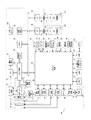
図1は、本発明の実施形態の構成を示す図である。図1において、100は画像処理装置である。10は変倍系レンズ群、11は合焦系レンズ群、12は絞り機能を備えるシャッター、14は光学像を電気信号に変換する撮像素子、15は撮像素子14の感度を設定する撮像感度調節手段であり、本実施形態においては0〜24dBまでリニアに調節可能なゲインアンプを採用している。
【0030】
16は撮像素子14のアナログ信号出力をデジタル信号に変換するA/D変換器、18は撮像素子14、A/D変換器16およびD/A変換器26にクロック信号や制御信号を供給するタイミング発生回路であり、メモリ制御回路22およびシステム制御回路50によって制御される。変倍系レンズ群10による変倍率はワイド(Wide)端からテレ(Tele)端までを8分割し、Wide端とTele端を含めて9ポジションの変倍を可能とする構成を採用している。
【0031】
20は画像処理回路であり、A/D変換器16からのデータあるいはメモリ制御回路22からのデータに対して所定の画素補間処理や色変換処理を行う。画像処理回路20においては、撮像した画像データを用いて所定の演算処理を行い、得られた演算結果に基づいてシステム制御回路50が自動露出制御手段40および測距制御手段42に対して制御を行うTTL方式のAF(オートフォーカス)処理、AE(自動露出)処理、EF(フラッシュプリ発光)処理を行っている。さらに、画像処理回路20において、撮像した画像データを用いて所定の演算処理を行い、得られた演算結果に基づいてTTL方式のAWB(オートホワイトバランス)処理も行っている。
【0032】
22はメモリ制御回路であり、A/D変換器16、タイミング発生回路18、画像処理回路20、画像表示メモリ24、D/A変換器26、メモリ30および圧縮・伸長回路32を制御する。A/D変換器16のデータが画像処理回路20およびメモリ制御回路22を介して、あるいはA/D変換器16のデータが直接メモリ制御回路22を介して、画像表示メモリ24あるいはメモリ30に書き込まれる。
【0033】
24は画像表示メモリ、26はD/A変換器、28はTFTLCD等から成る画像表示部である。画像表示メモリ24に書き込まれた表示用の画像データは、D/A変換器26を介して画像表示部28により表示される。画像表示部28を用いて撮像した画像データを逐次表示すれば、電子ファインダー機能を実現することができる。また画像表示部28は、システム制御回路50の指示により任意に表示をON/OFFすることができ、表示をOFFにした場合には画像処理装置100の電力消費を大幅に低減することができる。
【0034】
30は撮影した静止画像や動画像を格納するためのメモリであり、所定枚数の静止画像や所定時間の動画像を格納するために十分な記憶容量を備えている。これにより、複数枚の静止画像を連続して撮影する連射撮影やパノラマ撮影の場合にも、高速かつ大量の画像をメモリ30に書き込むことができる。また、メモリ30はシステム制御回路50の作業領域としても使用することができる。
【0035】
32は適応離散コサイン変換(ADCT)等により画像データを圧縮および伸長する圧縮・伸長回路である。圧縮・伸長回路32は、メモリ30に格納された画像を読み込んで圧縮処理または伸長処理を行い、処理を終えたデータをメモリ30に書き込む。
【0036】
40は絞り機能を備えるシャッター12と、タイミング発生回路18により撮像素子14の電荷排出動作から読み出し動作までの蓄積時間を制御する電子シャッター制御手段と、撮像感度調節手段15とを制御する自動露出制御手段であり、フラッシュ48と連携することによりフラッシュ調光機能も有している。42は合焦系レンズ11のフォーカシングを制御する測距制御手段、44は変倍系レンズ10のズーミングを制御するズーム制御手段、46はバリアである保護手段102の動作を制御するバリア制御手段である。48はフラッシュであり、AF補助光の投光機能、フラッシュ調光機能も有する。露出制御手段40、測距制御手段42はTTL方式を用いて制御されており、撮像した画像データを画像処理回路20によって演算した演算結果に基づき、システム制御回路50が露出制御手段40および測距制御手段42に対して制御を行う。自動露出制御の詳細については後に述べることとする。
【0037】
50は画像処理装置100全体を制御するシステム制御回路、52はシステム制御回路50の動作用の定数、変数およびプログラム等を記憶するメモリ、54はシステム制御回路50でのプログラムの実行に応じて、文字、画像および音声等を用いて動作状態やメッセージ等を表示する液晶表示装置やスピーカー等を含む表示部である。表示部54は画像処理装置100の操作部近辺の視認し易い位置に単数あるいは複数個所設置され、たとえばLCDやLED発音素子等の組合わせにより構成されている。表示部54はまた、その一部の機能が光学ファインダー104内に設置されている。
【0038】
表示部54の表示内容のうち、LCD等に表示するものとしてはシングルショット/連写撮影表示、長秒時撮影表示、夜景撮影表示、セルフタイマー表示、圧縮率表示、記録画素数表示、記録枚数表示、残撮影可能枚数表示、シャッタースピード表示、絞り値表示、露出補正表示、フラッシュ表示、赤目緩和表示、(赤目緩和ランプ点灯、前回の撮影からの)経過時間表示、マクロ撮影表示、ブザー設定表示、時計用電池残量表示、電池残量表示、エラー表示、複数桁の数字による情報表示、記録媒体200および210の着脱状態表示、通信I/F動作表示および日付・時刻表示等が含まれる。また、表示部54の表示内容のうち、光学ファインダー104内に表示するものとしては合焦表示、手振れ警告表示、フラッシュ充電表示、シャッタースピード表示、絞り値表示および露出補正表示等が含まれる。
【0039】
56は電気的に消去および記録可能な不揮発性メモリであり、この不揮発性メモリ56にはたとえばEEPRPM等が用いられる。
【0040】
60、62、64、66、68および70は、システム制御回路50の各種の動作指示を入力するための操作手段であり、スイッチやダイアル、タッチパネル、視線検知によるポインティング、音声認識装置等の単数あるいは複数の組合わせで構成される。ここで、これらの操作手段の具体的な説明を行う。60はモードダイアルスイッチであり、電源オフ、自動撮影モード、撮影モード、パノラマ撮影モード、再生モード、マルチ画面再生・消去モード、PC接続モード等の各機能モードを切り替え設定することができる。
【0041】
62はシャッタースイッチSW1であり、図示しないシャッターボタンの操作途中でONとなって、AF処理、AE処理、AWB処理、EF処理等の動作開始を指示する。
64はシャッタースイッチSW2であり、図示しないシャッターボタンの操作完了でONとなって、撮像素子12から読み出した信号をA/D変換器16、メモリ制御回路22を介してメモリ30に画像データを書き込む露光処理、画像処理回路20やメモリ制御回路22での演算を用いた現像処理、メモリ30から画像データを読み出し、圧縮・伸長回路32で圧縮を行い、記録媒体200あるいは210に画像データを書き込む記録処理などの一連の処理の動作開始を指示する。
【0042】
66は画像表示ON/OFFスイッチであり、画像表示部28のON/OFFを設定することができる。この機能により、光学ファインダー104を用いて撮影を行う際にTFTLCD等からなる画像表示部への電流供給を遮断することにより、省電力を図ることが可能となる。
【0043】
70は各種ボタンやタッチパネル等からなる操作部であり、メニューボタン、セットボタン、マクロ/非マクロ切替えボタン、マルチ画面再生改ページボタン、フラッシュ設定ボタン、単写/連写/セルフタイマー/長秒時(スローシャッター)/夜景撮影モード切替えボタン、メニュー移動+(プラス)ボタン、メニュー移動−(マイナス)ボタン、再生画像移動+(プラス)ボタン、再生画像−(マイナス)ボタン、撮影画質選択ボタン、露出補正ボタンおよび日付/時間設定ボタン等を含んでいる。
【0044】
80は電源制御手段であり、電池検出回路、DC−DCコンバータおよび通電するブロックを切り替えるためのスイッチ回路等により構成されている。そして電池の装着の有無、電池の種類、電池残量の検出を行い、検出結果およびシステム制御回路50の指示に基づいてDC−DCコンバータを制御し、必要な電圧を必要な期間だけ記録媒体を含む各部へ供給する。82および84はそれぞれコネクタ、86はアルカリ電池やリチウム電池等の一次電池やNiCd電池やNiMH電池、Li電池等の二次電池、ACアダプター等からなる電源手段である。
【0045】
90および94はメモリカードやハードディスク等の記録媒体とのインタフェース、92および96はメモリカードやハードディスク等の記録媒体と接続を行うコネクタ、98はコネクタ92あるいは96に記録媒体200あるいは210が装着されているか否かを検知する記録媒体着脱検知手段である。なお、本実施形態では記録媒体を取り付けるインターフェースおよびコネクタを2系統持っている。もちろん記録媒体を取り付けるインターフェースおよびコネクタは、単数あるいは複数の系統数を備える構成としてもよい。また、異なる規格のインターフェースおよびコネクタを組み合わせて備える構成としてもよい。また、インターフェースおよびコネクタとしては、PCMCIAカードやCF(コンパクトフラッシュ)カード等の規格に準拠したものを用いて構成してもよい。
【0046】
さらに、インタフェース90,94およびコネクタ92,96をPCMCIAカードやCFカード等の規格に準拠したものを用いて構成した場合、LANカードやモデムカード、USBカード、IEEE1394カード、P1284カード、SCSIカード、PHS等の通信カード、等の各種通信カードを接続することにより、他のコンピュータやプリンタ等の周辺機器との間で画像データや画像データに付属した管理情報を転送し合うことができる。
【0047】
102は撮像部の汚れや破損を防止するバリアである保護手段であり、画像処理装置100の変倍系レンズ10および合焦系レンズ11を含む撮像部を覆うようになっている。れや破損を防止するバリアである保護手段である。
104は光学ファインダであり、画像表示部28による電子ファインダー機能を使用すること無しに、光学ファインダのみを用いて撮影を行うことが可能である。また、光学ファインダー104内には表示部54の一部の機能、たとえば合焦表示、手振れ警告表示、フラッシュ充電表示、シャッタースピード表示、絞り値表示、露出補正表示およびマクロ撮影設定表示等が設置されている。
【0048】
110は通信手段であり、RS232CやUSB、IEEE1394、P1284、SCSI、モデム、LANおよび無線通信等の各種通信機能を有する。
112は通信手段110により画像処理装置100を他の機器と接続するコネクタあるいは無線通信の場合はアンテナである。
【0049】
200はメモリカードやハードディスク等の記録媒体である。記録媒体200は、半導体メモリや磁気ディスク等から構成される記録部202、画像処理装置100とのインタフェース204および画像処理装置100との接続を行うコネクタ206を備えている。
210はメモリカードやハードディスク等の記録媒体である。記録媒体210は、半導体メモリや磁気ディスク等から構成される記録部212、画像処理装置100とのインタフェース214および画像処理装置100との接続を行うコネクタ216を備えている。
【0050】
ここで、図5〜図9は本実施形態における自動露出制御手段のフローチャートを示している。この実施形態の自動露出制御手段は、システム制御回路50のプログラム領域52に書き込まれ、CPUによる演算結果に基づいて露出制御手段40を制御して行う。また、この自動露出制御は撮影動作準備期間、本露光動作直前、画像表示部28への画像表示準備期間、画像表示部28への画像表示中に応じて、露出制御速度や露出制御精度を一義的に決定して制御を行うようにしている。この自動露出制御は内部状態を記憶し、その状態の遷移に応じて、自らの露出制御方法を決定していく。
【0051】
また、システム制御回路50は自動露出制御手段を起動するときに動作期間を特定するモード指定している。この動作期間を特定するモードによって、測光の方式と絞り12の制御、タイミング発生回路18による撮像素子14の電荷排出動作から読出し動作までの蓄積時間を制御する電子シャッター制御および撮像感度調節手段15の制御値を、被写体輝度から一義的に求められるように構成したプログラム線図を変更しながら制御を行う。
【0052】
本自動露出制御手段の基本構造は、図12に示される。自動露出制御手段のサブシステムには、上述した絞り12の制御手段、タイミング発生回路18による撮像素子14の電荷排出動作から読出し動作までの蓄積時間を制御する電子シャッター制御手段および撮像感度調節手段15の制御手段が存在する。また、これに加えて測光手段、プログラム線図およびこのプログラム線図を解析して露出制御値を算出する露出制御値算出手段が存在する。撮像素子14を使用したTTL測光の場合、撮像素子14のダイナミックレンジが狭いため、自動露出制御の連動範囲内の全ての輝度に対して一度で測光することができない。通常、一度に測光可能な範囲は略4段程度である。
【0053】
図11は、相対的測光方式を示した自動露出制御のタイミングチャートを示している。
自動露出制御手段は、被写界輝度(Bv )値とプログラム線図から一義的に決定する露出制御値、すなわち絞り制御(Av )値、電子シャッター制御(Tv )値および撮像感度調節(DG)値を求め、各制御値をサブシステムの各制御手段に引き渡す。サブシステムの絞り制御手段、電子シャッター制御手段および撮像感度調節手段は、引き渡されたAv 値、Tv 値およびDG値をそれぞれが制御するデバイスに依存した実制御データに換算し、露出制御手段40に対して制御を行う。なお、各デバイス依存の制御データおよび制御方法の詳細については省略する。ただし、撮像素子の電荷排出動作を意味するクリアパルスの設定は、設定完了時点からつぎに現れる電荷読出し動作を意味する読出しパルスを境にして有効になるものとする。
【0054】
自動露出制御手段は、図11における第1の制御から撮像素子の露光完了を待つ。画像処理回路20は、撮像素子14から読み出される電荷信号をA/D変換器16を介して逐次読み込み、システム制御回路50が予め設定した積分領域を分割した領域ごとに光束積分を行う。撮像素子14の露光が行われたつぎの垂直同期期間内で、測光手段は積分された光束積分の結果を領域の終了と共に画像処理回路20から読み出す。測光手段は、この分割された各領域ごとの積分結果を各領域ごとに、1画素単位の積分値に換算したの後、分割された領域の面積比率に応じた各領域ごとの評価値を演算する。
【0055】
なお、画像処理回路20には、積分回路の他に入力された画像データ中の輝度成分のレベル毎に各レベルの検出度合いを示す頻度をカウントすることが(以下、輝度分布抽出手段)可能である。また、測光手段は各領域内の1画素単位で高輝度および低輝度の閾値を持ち、各領域毎の評価値を演算する際にその閾値を越え、あるいは下回る画素のデータは破棄して演算する。測光手段はさらに、各領域ごとの評価値に所定の重み付けを行う。そして、評価測光、中央重点測光およびスポット測光等の測光モードに応じて適正露出レベルからのずれ量に相当する輝度(ΔBv)値を算出する。勿論、画像処理回路20内に構成し、積分或いは、輝度分布生成時に余分なデータを排除してもよい。
【0056】
自動露出制御手段は、演算結果で得られたΔBv 値を前回の制御に用いたBv 値に加算して、つぎの目標Bv 値を算出し、プログラム線図から一義的に決定されるつぎの目標露出制御値を算出する。求められた各制御値を各制御手段に入力し、ΔBv 値が所定の範囲内に入るまで測光と制御を繰り返す。したがって、2つの垂直同期期間を使って、一度の露出制御が行われることになる。
【0057】
図11に示すタイミングチャートでは、第1の演算結果によって決定したつぎの目標露出制御値に基づく露出制御動作が、つぎの撮像素子の露光時間にまたがらない範囲、すなわち撮像素子のクリアパルスが停止する前までに制御が完了している。なお、被写界輝度によっては必ずしもこれが保証されるものではない。したがって、第1の演算結果によって決定したつぎの目標露出制御値に基づく露出制御動作が、撮像素子のクリアパルスにまたがってしまう程露光時間が長い場合には、つぎの撮像素子の露出結果を使用せずに、更につぎの垂直転送パルス、すなわち撮像素子の読み出しパルスが出力されるまで積分されたデータを使用できなくなる。先に2つの垂直同期期間で一度の露出制御が行われる説明したが、実際には2〜3つの垂直同期期間で一度の露出制御になる。もちろん、輝度分布抽出手段によるヒストグラム生成時にも同様のことが言える。
【0058】
画像表示部28に撮像した画像をスルー表示する状態では、使用者が画角を決定するために被写界輝度が大きく変化することがある。この状態で被写界輝度にダイレクトに反応して露出制御を行うと、画像表示部28に表示されるが画像の輝度変化が激しくなって、見苦しい状態になる場合がある。そのため測光と制御を繰り返す判断となるΔBv 値の範囲(適正露出範囲)が広く、一旦ΔBV 値が適正露出範囲内に入ると、ΔBv 値が適正露出範囲よりも広い露出監視範囲を超えるまでは制御を行わず、測光のみを行う。また、制御を伴う測光したΔBv 値の大きさに応じて、目標Bv 値を算出する際に加算するΔBv 値を除算圧縮することにより、適正露出が得られるまでの時間を遅らせている。このように画像表示中の自動露出制御は時間的に余裕があるので、相対的な測光方式でも問題はない。
【0059】
先にも述べた通り、撮像素子を利用したTTL測光方式では、撮像素子のダイナミックレンジの幅が略4段程度であるため、一度に連動範囲すべてを測光することができない。そのため測光動作を開始するときには、標準的な仮想被写界輝度(Start Bv )値を使って制御を行い、相対的に被写界輝度値を探って行くとよい。しかしながら、測光開始時のStart Bv 値と実際のBv 値との差が大きければ大きいほど、適正露出が得られるまでの時間が長くかかってしまう。つまり一旦適正露出が得られた後で行う相対的な測光方式は、画像表示中の自動露出制御に使用可能であるが、撮影準備期間や画像表示部に表示する画像を生成する時などの時間的に余裕のない場合に行う測光方式には適さない。
【0060】
図10に示すタイミングチャートは、撮影準備期間や、画像表示部に表示する画像を生成する時などの時間的に余裕のない場合に行うスキャン測光方式を用いた場合の自動露出制御を示したものである。
この実施形態の撮像素子のダイナミックレンジが、適正露出時の1画素当たりの積分値を基準にした場合、高輝度側に1段、低輝度側に3段の測光が可能であるとする。また、自動露出制御の連動範囲をISO100換算のEv 値(なお、Ev =Bv +Sv 、Sv =5)で表現すると、Ev 7からEv 17であるとする。さらに自動露出制御手段は、第1の制御値Ev 16、第2の制御値Ev 13および第3の制御値Ev 10をデータとして持つ。
【0061】
第1の制御値で測光可能な範囲は、Ev13からEv17であり、第2の制御値で測光可能な範囲は、Ev10からEv14、第3の制御値で測光可能な範囲はEv7からEv11になる。また、これらの制御値は詳細には撮像素子14や絞りの仕様によって変化する。図8に示した測光方式のフローチャートでは、Av値およびDG値は、いずれの制御値に対しても共通に固定値であり、Tv値のみで制御する場合の動作である
【0062】
つぎに、図10のタイミングチャートを参照して動作を説明する。
まず、相対的な測光方式時と同様に、自動露出制御手段は、第1の制御値を各制御手段に入力し、各デバイスに依存した実制御値に換算した後に露出制御手段40に対して制御をかける。制御を行うタイミングは、図12に示すようにクリアパルス設定は垂直同期信号の立下り付近で行い、絞り設定は読出しパルス後付近で行うことにする。図示しない撮像感度の設定はクリアパルス設定と同じタイミングで行う。
【0063】
第1の制御を行った垂直同期期間では、撮像素子に露光のみを行い、光束積分は行って結果を使用しないか、積分を行わなくてもよい。第1の露光中に発生する第2の垂直同期信号の立下りのタイミングで第2の電子シャッター制御を行い、読み出しパルスのタイミングで絞り制御を行う。第2の制御を行った第2の垂直同期期間では、第2の撮像素子の露光と共に、第1の垂直同期期間に露光した画像の光束積分を行い、積分領域終了に伴って第1の積分結果を読み出し、第1のΔBv値を求める。また、第1の垂直同期期間と同様に撮像素子の第2の露光中に発生する第3の垂直同期信号の立下りのタイミングで、第3の電子シャッター制御を行い、読み出しパルスのタイミングで絞り制御を行う。また、第2の垂直同期期間と同様に第3の垂直同期期間の制御を行う。第3の露光を行った次の第4の垂直同期期間では、第3の光束積分と第3のΔBv値の算出を行い、過去の3つの垂直同期期間内に算出したΔBv値の中から択一する。択一されたΔBvと、このΔBv値を測光した時の露出制御値から目標ΔBv値を求め、プログラム線図から一義的に決定される目標制御値を算出して制御を行う。
【0064】
ΔBv 値の択一方法は特に問わない。たとえば、測光したBv 値がEv 13からEv 14までに存在していた場合において、積分結果のリニアリティを重視するのであれば、第1のΔBv 値と第1の制御値から決定する目標Bv 値を採択する。あるいは絞りの開口径による回折回避を重視するのであれば、第2のΔBv 値と第2の制御値から決定する目標Bv 値を採択する。
【0065】
このように撮像素子のダイナミックレンジを1段分オーバーラップさせて連動範囲全てを網羅するように測光を行うことによって、3つの垂直同期期間内に被写界輝度を測光することができる。したがって、画像表示部28に画像を表示する前に行う自動露出制御や、撮影直前に行う露出制御のように速度を優先する状態に有効である。
【0066】
なお、上記説明では高輝度側から測光を行ったが、順序に関する組合わせは本発明の本質には関与するものではない。また、第1、第2および第3の制御値が電子シャッターのみが変化するように構成してもよい。また、すべてを絞りまたは撮像感度調節値のみの制御で行ってもよい。この組合わせは、読出しパルスのタイミングからクリアパルスが停止するまでの時間内に絞りが制定するか、または撮像感度が切り替わるかによって決定する事項である。さらに本実施形態ではオーバーラップさせる量を1段分としたが、これに限定されるものはない。
【0067】
さらに、本実施形態においては須らく予め決定している制御、積分および測光演算をすべて行っているが、たとえば第1の測光結果が得られた時点で適正露出であると判断可能な場合にそれ以降の制御、積分および測光演算を禁止したり、制御の順序を変更したり、あるいは特定の制御を省くなどの応用が可能である。また、スキャン測光方式における測光部分を画像処理回路20の積分手段ではなく、輝度分布抽出手段によるヒストグラムで行って、ヒストグラムにおける輝度分布の偏差が所定範囲に入ったところで制御、露光を止めるように構成することもできる。
【0068】
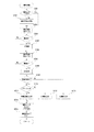
つぎに、図5を用いて自動露出制御の動作を説明する。
まず、自動露出制御手段を起動すると、起動された自動露出制御手段は、現在のモードを認識する(ステップS501)。モード変更が認められた場合(ステップS502)には、適正露出フラグを解除して直前のモードにおける被写界輝度を記憶する(ステップS503)。
つぎに、プログラム線図を選択し(ステップS504)し、露出制御値算出手段に登録する(ステップS505)。
つぎに、測光に必要な測光領域設定等を行う(ステップS506)。
【0069】
画像表示期間モード(Mode=2)で起動された場合等、モード変更がない場合には引き続きの露出制御を行う(ステップS510へ)。
【0070】
モード変更がなされ、かつ画像表示期間モード(Mode=2)あるいは本露光動作直前モード(Mode=4)であった場合(ステップS507)には、ステップS503で記憶した被写界輝度値をBv 値とし、Sv 値を加えて露出制御値算出手段に入力し、初期Av 値、Tv 値およびDG値を求める(ステップS508)。
つぎに、それぞれ絞り制御手段、電子シャッター手段および撮像感度調節手段で制御を行う(ステップS509)。露出制御(ステップS509)においては前述したようにそれぞれデバイスに依存した制御データに変換した後、絞り12、電子シャッターおよび撮像感度を制御する。また、図示されていないが、それぞれの制御手段は、最後に設定した制御値あるいは最後に制御した制御データを記憶する。同一の制御値あるいは制御データであった場合には、実際の制御を行わない。また、設定タイミングも持ち合わせ、割込み処理等のタイミング発生手段については特に規定しない。
【0071】
続いて測光手段を起動して測光を行い、Bv値およびΔBv値を得る(ステップS510)。画像表示期間モード(Mode=2)あるいは本露光動作直前モード(Mode=4)であった場合(ステップS511)には、適正露出フラグ状態を調べる(ステップS515)。ON状態であった場合には、測光したΔBv値が露出監視範囲内であるかを調べる(ステップS516)。範囲内であった場合には何もせずに戻る。また、露出監視範囲内でなかった場合(ステップS516)および適性露出フラグがOFF状態であった場合(ステップS517)には、測光した目標Bv値にSv値を加えて露出制御値算出手段に入力し、目標Av値、Tv値およびDC値を求め(ステップS517)、各制御値に基づいて制御処理を行う(ステップS518)。
【0072】
つぎに、測光したΔBv 値が制御用の適正露出範囲内であるかを調べ(ステップS519)、範囲内にあるときにのみ適性露出フラグを設定して(ステップS520)戻る。
【0073】
引き続き、露出制御内で行う測光制御(S510)について図7を用いて説明する。
まず、画像表示準備期間(Mode=1)であるか否かを判定する(ステップS531)。
画像表示準備期間であった場合には、スキャン測光を行って(ステップS532)戻る。
【0074】
画像表示準備期間モードでなかった場合には、画像表示期間モード(Mode=2)であるかを判定する(ステップS533)。
画像表示期間モードであった場合には相対測光を行って(ステップS534)戻る。
【0075】
画像表示期間モードでなかった場合には、撮影準備動作期間モード(Mode=3)であるかを判定する(ステップS535)。撮影準備動作期間モードであった場合には、画像表示フラグを判定する(ステップS536)。画像表示フラグがON設定されている場合には、モード変更時(ステップS503)に記憶した直前のモードにおける被写界輝度を戻す(ステップS537)。画像表示フラグが設定されていない場合には、スキャン測光を行って(ステップS538)戻る。
【0076】
いずれのモードにも当てはまらないと判断した場合は(ステップS535)、モードを本露光動作直前モード(Mode=4)であるとして相対測光を行って戻る(ステップS539)。
【0077】
ここで図8は、スキャン測光の動作が電子シャッターのみで制御を行われた場合を示す。また図9は、相対測光の動作を示したものである。これらの動作は、先のタイミングチャート(図10)で説明した通りである。
【0078】
つぎに、図2および図3を用いて、画像処理装置100の動作を説明する。
電池交換等の電源投入により、システム制御回路50はフラグや制御変数等を初期化し(ステップS101)、画像表示部28の画像表示をOFF状態に初期設定する(ステップS102)。
【0079】
システム制御回路50は、モードダイアル60の設定位置を判断し、モードダイアル60が電源OFFに設定されていたならば(ステップS103)、各表示部の表示を終了状態に変更する。そして保護手段102のバリアを閉じて撮像部を保護し、フラグや制御変数等を含む必要なパラメータや設定値、設定モードを不揮発性メモリ56に記録する。電源制御手段80により画像表示部28を含む画像処理装置100各部の不要な電源を遮断する等の所定の終了処理を行った後(ステップS105)、ステップS103に戻る。
【0080】
モードダイアル60が撮影モードに設定されていれば(ステップS103)、ステップS106に進む。モードダイアル60がその他のモードに設定されていたならば(ステップS103)、システム制御回路50は選択されたモードに応じた処理を実行し(ステップS104)、処理を終えたならばステップS103に戻る。
【0081】
ここで、図示しない保護手段102のバリアを閉じる動作についてさらに説明する。
システム制御回路50は、保護手段102を動作させる前に必要とされないレンズ群10,11をカメラ内に格納するため変倍系レンズ群10と合焦系レンズ群11それぞれの位置検出を行う。変倍系レンズ群10を繰り出していると判断した場合には、合焦系レンズ群11を沈胴待機位置まで繰り込んだ後で変倍系レンズ群10を沈胴位置まで繰り込む。変倍系レンズ群10の繰り込みとシンクロさせながら保護手段102のバリアを閉じて終了する。本実施形態においては保護手段102のバリア制御を独立したバリア制御手段46で駆動しているが、機械的に変倍系レンズ群10の駆動に連動して駆動する方式を取ることも可能である。
【0082】
システム制御回路50は、電源制御手段80により電池等により構成される電源86の残容量や動作状況が画像処理装置100の動作に問題があるか否かを判断する(ステップS106)。問題があれば表示部54を用いて画像や音声により所定の警告表示を行った後(ステップS108)、ステップS103に戻る。電源86に問題がないならば、システム制御回路50は記録媒体200あるいは210の動作状態が画像処理回路100の動作、特に記録媒体に対する画像データの記録再生動作に問題があるか否かを判断する(ステップS107)。問題があれば表示部54を用いて画像や音声により所定の警告表示を行った後(ステップS108)、ステップS103に戻る。記録媒体200あるいは210の動作状態に問題がないならば(ステップS107)、表示部54を用いて画像や音声により画像処理装置100の各種設定状態の表示を行う(ステップS109)。なお、画像表示部28の画像表示がONであったならば、画像表示部28も用いて画像や音声により画像処理装置100の各種設定状態の表示を行う。
【0083】
システム制御回路50は、画像表示フラグを調べ(ステップS110)、画像表示フラグがONに設定されていれば、露出制御を行い(ステップS116)、ステップS119に進む。
【0084】
画像表示フラグがOFFに設定されていれば(ステップS110)、画像表示ON/OFFスイッチ66の設定状態を調べ(ステップS111)、画像表示がONに設定されていれば、撮像手段を起動して(ステップS112)、露出制御(Mode=1)を行う(ステップS113)。適正露出が得られたら、撮像した画像データを逐次表示するスルー表示状態に設定して、画像表示部28の画像表示をON状態に設定後(ステップS114)、画像表示フラグを設定し(ステップS115)、ステップS119に進む。
【0085】
画像表示状態において撮像素子12、A/D変換器16、画像処理回路20およびメモリ制御回路22を介して、画像表示メモリ24に逐次書き込まれたデータを、メモリ制御回路22およびD/A変換器26を介して画像表示部28により逐次表示することにより、電子ファインダ機能を実現している。
【0086】
画像表示ON/OFFスイッチ66が画像表示OFFに設定されていれば(ステップS111)、画像表示フラグを解除すると共に(ステップS117)、画像表示部28の画像表示をOFF状態に設定して(ステップS118)、ステップS120に進む。画像表示OFFの場合は、画像表示部28による電子ファインダ機能を使用せず、光学ファインダ104を用いて撮影を行う。この場合、電力消費量の大きい画像表示部28やD/A変換器26等の消費電力を削減することが可能となる。なお、画像表示フラグの状態は、システム制御回路50の内部メモリあるいはメモリ52に記憶する。
【0087】
自動露出制御のアルゴリズムを使用して、ステップS113においてMode=1に指定して自動露出制御を起動すると、スキャン測光によるBv値に基づいて制御を行って被写界輝度を短時間で測定する。また、その他の操作が行われずに、Mode=2を指定して自動露出制御が起動された場合、測光したΔBv値に応じて制御もしくは監視が行われる。図示されていないが、制御を行う場合には測光したΔBv値の大きさに応じて除算圧縮を行った後にプログラム線図から制御値を求めている。こうすることにより、表示されている画像の輝度的変化がある時定数をもって制御される。
【0088】
制御を伴わない輝度監視状態にある場合において、輝度変化が認められてからタイマを起動し、所定時間経過した後でも輝度変化があった場合に制御に遷移するようにアルゴリズムを変更してもよい。また、輝度監視状態における適正露出範囲や、露出制御状態における適正露出範囲はMode=1〜4まで同一にせずにモードに応じて、広げたり狭めてもよい。特に画像表示中モード(Mode=2)の露出監視範囲または適正露出範囲を広げることにより、画像表示中の画像表示部28に表示される画像の輝度変化をより緩やかに制御することができる。
【0089】
続いて、撮影動作に纏わる動作を説明する。
シャッタースイッチSW1が押されていなければ(ステップS119)、ステップS103に戻る。シャッタースイッチSW1が押されたならば(ステップS119)、システム制御回路50はシステム制御回路50の内部メモリあるいはメモリ52に記憶される画像表示フラグの状態を判断する(ステップS120)、画像表示フラグが設定されていたならば画像表示部28の表示状態をフリーズ表示状態に設定して(ステップS121)、ステップS122に進む。フリーズ表示状態においては、撮像素子12、A/D変換器16、画像処理回路20、メモリ制御回路22を介した画像表示メモリ24の画像データ書き換えを禁止し、最後に書き込まれた画像データを、メモリ制御回路22およびD/A変換器26を介して画像表示部28により表示することにより、フリーズした映像を電子ファインダーに表示している。画像表示フラグが解除されていれば(ステップS120)、ステップS122に進む。
【0090】
この測距・測光処理(ステップS122)を図4により詳細に説明する。
まずシステム制御回路50は、画像表示フラグの設定状態を調べる(ステップS201)、設定されていない場合には撮像手段を起動して(ステップS202)、撮像素子14から電荷信号を読み出し、A/D変換器16を介して画像処理回路20に撮影画像データを逐次読み込む。
【0091】
つぎに、システム制御回路50は、自動露出制御手段を撮影準備期間モード(Mode=3)で起動し(ステップS203)、TTLAFにおける測距領域を適正露出にする(ステップS204)。引き続きTTLAFによる測距処理を行って合焦系レンズ11の焦点を被写体に合わせる(ステップS205)。さらに自動露出制御手段を撮影直前モードで起動し、最後に画面全体の評価測光処理を行って絞り値、シャッター時間および撮像感度調節値を決定する(ステップS206)。また、適正露出が得られた後に(ステップS207)、システム制御回路50はホワイトバランスが適正と判断されるまで画像処理回路20を用いて色処理のパラメータを調節してAWB制御を行う(ステップS208)。
【0092】
露出が適正と判断したならば、測定データおよび設定パラメータをシステム制御回路50の内部メモリあるいはメモリ52に保存記憶する。続いて露出制御で決定されたBv 値から本露光時の撮影条件下でのシャッター秒時を算出する。このときにはプログラム線図を一旦本露光用に切り替えて算出し、算出した後に元のプログラム線図に戻している。この際、演算のみで制御を行わない。
【0093】
算出されたシャッター秒時が所定(手振れ限界)値以下であった場合において(ステップS209)、フラッシュオフモードであれば(ステップS210)、表示部54の表示内容のうち光学ファインダー104内に表示する手振れ警告表示を行う(ステップS211)。フラッシュオフモード以外ならばEF撮影表示を行う(ステップS212)。また赤目緩和ランプを点灯するモードであった場合にも、手振れ限界以下では点灯を開始する。ステップS208において手振れ限界に満たなければ、AE撮影表示を行う(ステップS213)。
【0094】
さらに、上述した条件で決定された撮影モードのフラグを設定し(ステップS214)、撮影準備完了を示すブザーを鳴らす(ステップS215)。測距・測光処理(ステップS122)の終了後、システム制御回路50はシステム制御回路50の内部メモリあるいはメモリ52に記憶される画像表示フラグの状態を判断する(ステップS123)。画像表示フラグが設定されていたならば画像表示部28の表示状態をスルー表示状態に設定して(ステップS124)、ステップS125に進む。なお、ステップS124におけるスルー表示状態は、ステップS115でのスルー状態と同じ動作状態である。
【0095】
シャッタースイッチSW2が押されずに(ステップS125)、さらにシャッタースイッチSW1も解除されれば(ステップS126)、ステップS103に戻る。シャッタースイッチSW2が押された以降の撮影動作については、このでの説明を省略する。
【0096】
上述のように第1の測光手段を使用することにより、被写界輝度の状態に依らず一定の期間内に被写界輝度を測光できる。また、第1の測光手段で測光した後に第2の測光手段の出力を使用してフィードバックをかけることにより、高速でかつ精度のよい測光状態で撮影が可能になる。さらに、画像表示を行う前および画像表示を行わず、かつ撮影準備を行うときに第1の測光手段を使用し、それ以外は間隔をおいて測光を行う第2の測光手段を使用することで、画像処理部の積分回路を停止可能時間を多くし、短時間で低消費電力の測光が可能である。
【0097】
また、第1の測光手段における各制御下で測光可能なダイナミックレンジをオーバーラップさせることにより、測光のリニアリティを重視した測光が可能である。さらに、第1の測光手段における各制御下で測光可能なダイナミックレンジをオーバーラップさせないことにより、被写界輝度を把握するまでの消費時間を重視した露出制御を構成できる。さらに、第1の測光期間内で時分割して測光演算した結果がダイナミックレンジ内で測光可能であると判断した場合に、それ以降の制御、積分および測光演算のうち、少なくとも1つを禁止することにより、より高速な露出制御が可能になる。
【0098】
なお、本実施形態において画像表示を本装置内の画像表示部で行っているが、TFTLCD等からなる画像表示部28の代わりにビデオアンプとビデオ信号出力端子を備えて、装置外部の表示装置に表示する場合や通信手段110およびコネクタ112を用いて外部装置に画像データを転送して表示を行う場合においても同じ効果を発揮する。
【0099】
本発明は上述した実施形態の機能を実現するように各種のデバイスを動作させるように、各種デバイスと接続された装置あるいはシステム内のコンピュータに対し、上記実施形態の機能を実現するためのソフトウェアのプログラムコードを供給し、そのシステムあるいは装置のコンピュータ(CPUあるいはMPU)に格納されたプログラムに従って上記各種デバイスを動作させることによって実施したものも、本発明の範疇に含まれる。
【0100】
また、この場合、そのソフトウェアのプログラムコード自体が上述した実施形態の機能を実現することになり、そのプログラムコード自体、およびそのプログラムコードをコンピュータに供給するための手段、たとえばかかるプログラムコードを格納した記憶媒体は本発明を構成する。プログラムコードを記憶する記憶媒体としては、たとえばフロッピーディスク、ハードディスク、光ディスク、光磁気ディスク、CD−ROM、磁気テープ、不揮発性のメモリカード、ROM等を用いることができる。
【0101】
また、コンピュータが供給されたプログラムコードを実行することにより、上述の実施形態の機能が実現されるだけでなく、そのプログラムコードがコンピュータにおいて稼働しているOS(オペレーティングシステム)あるいは他のアプリケーションソフト等と共同して、上述の実施形態の機能が実現される場合にもそのプログラムコードは本発明の実施形態に含まれる。
【0102】
さらに、供給されたプログラムコードがコンピュータの機能拡張ボードやコンピュータに接続された機能拡張ユニットに備わるメモリに格納された後、そのプログラムコードの指示に基づいてその機能拡張ボードや機能拡張ユニットに備わるCPU等が実際の処理の一部または全部を行い、その処理によって上述した実施形態の機能が実現される場合にも本発明に含まれる。
【0103】
【発明の効果】
以上説明したように本発明によれば、固体撮像素子の出力を利用して自動露出制御を行う場合において、電子ファインダの状態に依らず、撮影準備動作期間を短縮し、かつ安定した時間内に測光および露光を行うための露出制御が可能になる。そして、本発明の総合的効果として、消費電力およびレリーズタイムラグを軽減し、シャッタータイミングを逃さない電子カメラ等の画像処理装置を構成することができる等の利点を有している。
【図面の簡単な説明】
【図1】本発明の実施形態における装置構成を示すブロック図である。
【図2】本発明の実施形態における主ルーチンを示すフローチャートである。
【図3】本発明の実施形態における主ルーチンを示すフローチャートである。
【図4】本発明の実施形態における測距・測光ルーチンを示すフローチャートである。
【図5】本発明の実施形態における露出制御のフローチャートである。
【図6】本発明の実施形態における露出制御処理のフローチャートである。
【図7】本発明の実施形態における測光のフローチャートである。
【図8】本発明の実施形態における第1の測光動作のフローチャートである。
【図9】本発明の実施形態における第2の測光動作のフローチャートである。
【図10】本発明の実施形態における第1の測光動作のタイミングチャートである。
【図11】本発明の実施形態における第2の測光動作のタイミングチャートである。
【図12】本発明の実施形態における自動露出制御の構成を示す図である。
【符号の説明】
10 変倍系レンズ
11 合焦系レンズ
12 シャッター
14 撮像素子
15 撮像感度調整手段
16 A/D変換器
18 タイミング発生回路
20 画像処理回路
22 メモリ制御回路
24 画像表示メモリ
26 D/A変換器
28 画像表示部
30 メモリ
32 画像圧縮・伸長回路
40 自動露出制御手段
42 測距制御手段
44 ズーム制御手段
46 バリア制御手段
48 フラッシュ
50 システム制御回路
52 メモリ
54 表示部
56 不揮発性メモリ
60 モードダイアルスイッチ
62 シャッタースイッチSW1
64 シャッタースイッチSW2
66 画像表示ON/OFFスイッチ
67 変倍レンズ駆動方向指示スイッチ(Tele)
68 クイックレビューON/OFFスイッチ
69 変倍レンズ駆動方向指示スイッチ(Wide)
70 操作部
80 電源制御手段
82 コネクタ
84 コネクタ
86 電源手段
90 インタフェース
92 コネクタ
94 インタフェース
96 コネクタ
98 記録媒体着脱検知手段
100 画像処理装置
102 保護手段
104 光学ファインダ
110 通信手段
112 コネクタ(またはアンテナ)
200 記録媒体
202 記録部
204 インタフェース
206 コネクタ
210 記録媒体
212 記録部
214 インタフェース
216 コネクタ[0001]
BACKGROUND OF THE INVENTION
The present invention provides an image processing apparatus for capturing, recording or reproducing still images and moving images.PlaceAndThatIt relates to a control method.
[0002]
[Prior art]
Conventionally, an image processing apparatus such as an electronic camera that records and reproduces still images and moving images using a memory card having a solid-state memory element as a recording medium is already on the market. Electronic cameras equipped with an electronic viewfinder such as a color liquid crystal panel are also on the market. According to these electronic cameras, by continuously displaying images obtained from the image sensor before photographing, it is possible for the user of the electronic camera to determine the composition or to reproduce and check the photographed images. is there.
[0003]
[Problems to be solved by the invention]
In such an image processing apparatus using an image sensor such as a conventional electronic camera, an object scene image incident from a lens via a diaphragm / shutter is formed on the image sensor. In general, image data obtained from an image sensor is divided into a plurality of pieces, and TTL (through-the-lens) exposure control is performed in accordance with light flux integration data obtained from each divided area.
[0004]
In this type of metering method, there is a limit to the luminance range that can be measured at once with the dynamic range of the imaging mechanism including the image sensor. Had to be done. That is, photometry is performed in a state in which the aperture and the shutter are controlled to a standard set value corresponding to the photographing mode, and the aperture or the shutter is controlled according to the difference from the data indicating the proper exposure of the luminous flux integral data. Then, it has been necessary to perform so-called feedback control in which the proper exposure is determined by performing photometry to converge.
[0005]
Such control varies in the time until a proper exposure is obtained depending on how much the standard setting value according to the shooting mode differs from the actual brightness and how much the dynamic range is. It means to end up.
[0006]
In addition, when using the electronic viewfinder, it is necessary for the user to adjust the angle of view, so the automatic exposure control mechanism is activated and the image displayed on the electronic viewfinder is in an approximately appropriate exposure state. It is common. In this case, since the luminance range of the object scene can be grasped before the shooting trigger occurs, the convergence time of the feedback control is shortened.
[0007]
However, on the other hand, power consumption increases. Therefore, when the power that can be supplied is reduced and shooting with the optical viewfinder without using the electronic viewfinder, a release time lag occurs when the shooting trigger is given in the same way as when using the electronic viewfinder, and the shutter timing There is a risk of missing.
[0008]
In view of such circumstances, the present invention is excellent in use and handling.,Proper exposure controlImage processing apparatus capable of performingandThatAn object is to provide a control method.
[0009]
[Means for Solving the Problems]
Of the present inventionThe image processing devicePhotoelectric conversion means for converting an optical image into an electrical signal;Display means for displaying an image based on the electrical signal converted by the photoelectric conversion means;A photometric means for obtaining a field luminance based on the electric signal converted by the photoelectric conversion means; an exposure control means for performing exposure control based on a photometric result of the photometric means;First photometry for obtaining a plurality of field luminances based on the electrical signal obtained by performing exposure a plurality of times under different exposure conditions in a plurality of vertical synchronization periods, and exposure once in the plurality of vertical synchronization periods Control means for controlling the photometry means to perform any one of the second photometry for obtaining the field luminance based on the electric signal obtained by performing the display, and the control means comprises the display Controlling the photometry means to perform the first photometry when the images are not sequentially displayed on the means, and repeatedly performing the second photometry while the images are sequentially displayed on the display means. The exposure control means selects and selects one field luminance from the plurality of field luminances determined by the first metering when the light metering means performs the first metering. Exposure control based on the controlled field brightness. The features.
[0010]
In addition, the present inventionThe control method includes a photoelectric conversion unit that converts an optical image into an electric signal, a display unit that displays an image based on the electric signal converted by the photoelectric conversion unit, and a target that is based on the electric signal converted by the photoelectric conversion unit. A photometry means for obtaining a field brightness, the exposure control step for performing exposure control based on a photometry result of the photometry means, and a plurality of times under different exposure conditions in a plurality of vertical synchronization periods. First photometry for determining a plurality of field luminances based on the electrical signal obtained by performing the exposure, and the electrical signal obtained based on the electrical signal obtained by performing the exposure once in the plurality of vertical synchronization periods. And a control step for controlling the photometry means so as to perform either one of the second photometry for obtaining the field luminance, and the control step does not sequentially display the image on the display means. Performing the first photometry, and controlling the photometry means so as to repeatedly perform the second photometry while the images are sequentially displayed on the display means, and the exposure control step includes the photometry means When performing the first photometry, one field luminance is selected from the plurality of field luminances determined by the first photometry, and exposure control is performed based on the selected field luminance. It is characterized by performing.
[0029]
DETAILED DESCRIPTION OF THE INVENTION
Hereinafter, embodiments of the present invention will be described with reference to the drawings.
FIG. 1 is a diagram showing a configuration of an embodiment of the present invention. In FIG. 1,
[0030]
16 is an A / D converter that converts the analog signal output of the
[0031]
An
[0032]
A
[0033]
[0034]
[0035]
A compression /
[0036]
[0037]
50 is a system control circuit that controls the entire
[0038]
Among the display contents of the
[0039]
[0040]
[0041]
Reference numeral 62 denotes a shutter switch SW1, which is turned on during the operation of a shutter button (not shown) and instructs to start operations such as AF processing, AE processing, AWB processing, and EF processing.
[0042]
[0043]
[0044]
[0045]
90 and 94 are interfaces with a recording medium such as a memory card and a hard disk, 92 and 96 are connectors for connecting to a recording medium such as a memory card and a hard disk, and 98 is a
[0046]
Further, when the
[0047]
A
[0048]
A
[0049]
[0050]
Here, FIGS. 5 to 9 show flowcharts of the automatic exposure control means in the present embodiment. The automatic exposure control means of this embodiment is written in the
[0051]
The
[0052]
The basic structure of this automatic exposure control means is shown in FIG. The sub-system of the automatic exposure control means includes the control means for the
[0053]
FIG. 11 shows a timing chart of automatic exposure control showing a relative photometry method.
The automatic exposure control means is an exposure control value that is uniquely determined from a field luminance (Bv) value and a program diagram, that is, an aperture control (Av) value, an electronic shutter control (Tv) value, and an imaging sensitivity adjustment (DG). A value is obtained, and each control value is transferred to each control means of the subsystem. The aperture control means, electronic shutter control means, and imaging sensitivity adjustment means of the subsystem convert the delivered Av value, Tv value, and DG value into actual control data depending on the devices that are controlled by each, and the exposure control means 40 Control is performed. Details of each device-dependent control data and control method are omitted. However, it is assumed that the setting of the clear pulse meaning the charge discharging operation of the image sensor becomes effective on the boundary of the readout pulse meaning the charge readout operation that appears next after the setting is completed.
[0054]
The automatic exposure control means waits for the completion of exposure of the image sensor from the first control in FIG. The
[0055]
The
[0056]
The automatic exposure control means adds the ΔBv value obtained as a result of the calculation to the Bv value used for the previous control, calculates the next target Bv value, and determines the next target uniquely determined from the program diagram. An exposure control value is calculated. Each calculated control value is input to each control means, and photometry and control are repeated until the ΔBv value falls within a predetermined range. Therefore, exposure control is performed once using two vertical synchronization periods.
[0057]
In the timing chart shown in FIG. 11, the next target exposure control value determined by the first calculation result.Exposure control operation based onHowever, the control is completed within a range that does not extend to the exposure time of the next image sensor, that is, before the clear pulse of the image sensor stops. Note that this is not necessarily guaranteed depending on the field luminance. Therefore, the next target exposure control value determined by the first calculation resultExposure control operation based onHowever, when the exposure time is long enough to extend over the clear pulse of the image sensor, the next vertical transfer pulse, that is, the readout pulse of the image sensor is output without using the exposure result of the next image sensor. The data integrated up to can no longer be used. Although it has been described above that exposure control is performed once in two vertical synchronization periods, actually, exposure control is performed once in two to three vertical synchronization periods. Of course, the same can be said when the histogram is generated by the luminance distribution extraction means.
[0058]
In a state in which the captured image is displayed on the
[0059]
As described above, in the TTL metering method using the image sensor, the width of the dynamic range of the image sensor is approximately four steps, and thus the entire interlocking range cannot be measured at a time. Therefore, when the photometric operation is started, it is preferable to perform control using a standard virtual field brightness (Start Bv) value and relatively search for the field brightness value. However, the larger the difference between the Start Bv value at the start of photometry and the actual Bv value, the longer it takes to obtain proper exposure. In other words, the relative photometry method that is performed once the proper exposure is obtained can be used for automatic exposure control during image display, but it can be used for shooting preparation periods and when generating images to be displayed on the image display section. This is not suitable for photometry when there is not enough room.
[0060]
The timing chart shown in FIG. 10 shows automatic exposure control when using a scanning photometry method that is performed when there is not enough time such as a shooting preparation period or when generating an image to be displayed on the image display unit. It is.
When the dynamic range of the image sensor of this embodiment is based on the integral value per pixel at the time of proper exposure, it is assumed that one-step photometry is possible on the high luminance side and three steps on the low luminance side. Further, when the interlocking range of the automatic exposure control is expressed by an Ev value in terms of ISO 100 (Ev = Bv + Sv, Sv = 5), it is assumed that Ev7 to Ev17. Further, the automatic exposure control means has a first
[0061]
The range in which photometry can be performed with the first control value is Ev13 to Ev17,With control valueThe meterable range is Ev10 to Ev14, and the meterable range with the third control value is Ev7 to Ev11. Further, these control values vary in detail depending on the specifications of the
[0062]
Next, the operation will be described with reference to the timing chart of FIG.
First, as in the case of the relative photometry method, the automatic exposure control means inputs the first control value to each control means, converts it to an actual control value depending on each device, and then to the exposure control means 40. Apply control. As shown in FIG. 12, the control timing is such that the clear pulse setting is performed near the falling edge of the vertical synchronization signal, and the aperture setting is performed near the readout pulse. The imaging sensitivity not shown is set at the same timing as the clear pulse setting.
[0063]
In the vertical synchronization period in which the first control is performed, only the image sensor is exposed, and the light beam integration is performed and the result is not used, or the integration may not be performed. Second electronic shutter control at the falling edge of the second vertical synchronization signal generated during the first exposureTheAperture control is performed at the timing of the readout pulse. In the second vertical synchronization period in which the second control is performed, the light beam integration of the image exposed in the first vertical synchronization period is performed together with the exposure of the second image sensor, and the first integration is performed when the integration region ends. The result is read to determine the first ΔBv value. Also, the first vertical synchronization periodWhenSimilarly of the image sensorSecondThe third electronic shutter control is performed at the falling timing of the third vertical synchronizing signal generated during the exposure, and the aperture control is performed at the timing of the readout pulse. Further, the third vertical synchronization period is controlled in the same manner as the second vertical synchronization period. In the fourth vertical synchronization period after the third exposure, the third light flux integration and the third ΔBv value are calculated, and selected from the ΔBv values calculated in the past three vertical synchronization periods. Do it. Control is performed by obtaining a target ΔBv value from the selected ΔBv and the exposure control value when the ΔBv value is measured, and calculating a target control value uniquely determined from the program diagram.
[0064]
The method for selecting the ΔBv value is not particularly limited. For example, when the photometric Bv value exists from Ev 13 to
[0065]
Thus, by performing photometry so that the dynamic range of the image sensor overlaps by one stage and covers the entire interlocking range, the field luminance can be measured within three vertical synchronization periods. Therefore, it is effective in a state where priority is given to speed, such as automatic exposure control performed before displaying an image on the
[0066]
In the above description, photometry is performed from the high luminance side, but the order combination is not related to the essence of the present invention. Further, the first, second, and third control values may be configured so that only the electronic shutter changes. Alternatively, all may be performed by controlling only the aperture or the imaging sensitivity adjustment value. This combination is a matter determined by whether the aperture is established within the time from the timing of the readout pulse until the clear pulse stops or whether the imaging sensitivity is switched. Further, in the present embodiment, the amount of overlap is one stage, but there is no limitation to this.
[0067]
Furthermore, in the present embodiment, all control, integration, and photometry calculations determined in advance are performed. For example, when it is possible to determine that the exposure is appropriate when the first photometry result is obtained, the subsequent steps are performed. Application such as prohibiting the control, integration and photometry calculation, changing the order of control, or omitting specific control is possible. Further, the photometry part in the scan photometry method is not performed by the integration means of the
[0068]
Next, the automatic exposure control operation will be described with reference to FIG.
First, when the automatic exposure control means is activated, the activated automatic exposure control means recognizes the current mode (step S501). When the mode change is recognized (step S502), the proper exposure flag is canceled and the field luminance in the immediately previous mode is stored (step S503).
Next, a program diagram is selected (step S504) and registered in the exposure control value calculation means (step S505).
Next, photometry area setting required for photometry is performed (step S506).
[0069]
When the mode is not changed, such as when the image display period mode (Mode = 2) is activated, the subsequent exposure control is performed (to step S510).
[0070]
When the mode is changed and the mode is the image display period mode (Mode = 2) or the mode immediately before the main exposure operation (Mode = 4) (Step S507), the field brightness value stored in Step S503 is set to the Bv value. The Sv value is added and input to the exposure control value calculation means, and the initial Av value, Tv value, and DG value are obtained (step S508).
Next, control is performed by an aperture control unit, an electronic shutter unit, and an imaging sensitivity adjustment unit, respectively (step S509). In the exposure control (step S509), as described above, after conversion into device-dependent control data, the
[0071]
Subsequently, the photometric means is activated to perform photometry, and the Bv value and ΔBv value are obtained (step S510). If the mode is the image display period mode (Mode = 2) or the mode immediately before the main exposure operation (Mode = 4) (step S511), the appropriate exposure flag state is checked (step S515). If it is ON,MeteredIt is checked whether the ΔBv value is within the exposure monitoring range (step S516). If it is within range, return without doing anything. Further, when it is not within the exposure monitoring range (step S516) and when the appropriate exposure flag is OFF (step S517), the Sv value is added to the photometric target Bv value and input to the exposure control value calculation means. Then, the target Av value, the Tv value, and the DC value are obtained (step S517), and the control process is performed based on each control value (step S518).
[0072]
Next, it is checked whether or not the photometric ΔBv value is within the appropriate exposure range for control (step S519). Only when it is within the range, the appropriate exposure flag is set (step S520), and the process returns.
[0073]
Next, photometric control (S510) performed within exposure control will be described with reference to FIG.
First, it is determined whether it is an image display preparation period (Mode = 1) (step S531).
If it is the image display preparation period, scan photometry is performed (step S532), and the process returns.
[0074]
If it is not the image display preparation period mode, it is determined whether the image display period mode (Mode = 2) is set (step S533).
If it is in the image display period mode, relative photometry is performed (step S534) and the process returns.
[0075]
If it is not the image display period mode, it is determined whether or not the shooting preparation operation period mode (Mode = 3) is set (step S535). If it is in the shooting preparation operation period mode, the image display flag is determined (step S536). When the image display flag is set to ON, when the mode is changed(Step S503)The field luminance in the immediately previous mode stored in (5) is returned (step S537). If the image display flag is not set, scan photometry is performed (step S538) and the process returns.
[0076]
If it is determined that neither mode is applicable (step S535), the mode is set to the mode immediately before the main exposure operation (Mode = 4), and the relative photometry is performed (step S539).
[0077]
Here, FIG. 8 shows a case where the scanning photometry operation is controlled only by the electronic shutter. FIG. 9 shows the operation of relative photometry. These operations are as described in the previous timing chart (FIG. 10).
[0078]
Next, the operation of the
Upon power-on such as battery replacement, the
[0079]
The
[0080]
If the
[0081]
Here, the operation of closing the barrier of the protection means 102 not shown will be further described.
The
[0082]
The
[0083]
The
[0084]
If the image display flag is set to OFF (step S110), the setting state of the image display ON /
[0085]
In the image display state, the data sequentially written in the
[0086]
If the image display ON /
[0087]
When automatic exposure control is activated by specifying Mode = 1 in step S113 using the automatic exposure control algorithm, control is performed based on the Bv value obtained by scanning photometry, and the field luminance is measured in a short time. Further, when the automatic exposure control is activated by specifying Mode = 2 without performing any other operation, the photometric ΔBv valueInControl or monitoring is performed accordingly. Although not shown, when control is performed, the control value is obtained from the program diagram after performing division compression according to the magnitude of the photometric ΔBv value. In this way, the brightness of the displayed image is controlled with a certain time constant.
[0088]
In the brightness monitoring state without control, the timer may be started after the brightness change is recognized, and the algorithm may be changed so as to shift to control when the brightness change has occurred even after a predetermined time has elapsed. . Further, the appropriate exposure range in the brightness monitoring state and the appropriate exposure range in the exposure control state may be expanded or narrowed according to the mode without making
[0089]
Subsequently, an operation related to the shooting operation will be described.
If the shutter switch SW1 has not been pressed (step S119), the process returns to step S103. If the shutter switch SW1 is pressed (step S119), the
[0090]
This distance measurement / photometry process (step S122) will be described in detail with reference to FIG.
First, the
[0091]
Next, the
[0092]
If it is determined that the exposure is appropriate, the measurement data and the setting parameters are stored in the internal memory of the
[0093]
When the calculated shutter time is equal to or less than a predetermined (shake limit) value (step S209), if the flash-off mode is set (step S210), the display contents of the
[0094]
Further, a flag for the shooting mode determined under the above-described conditions is set (step S214), and a buzzer indicating the completion of shooting preparation is sounded (step S215). After the distance measurement / photometry processing (step S122), the
[0095]
If the shutter switch SW2 is not pressed (step S125) and the shutter switch SW1 is also released (step S126), the process returns to step S103. A description of the shooting operation after the shutter switch SW2 is pressed will be omitted.
[0096]
By using the first photometry means as described above, the field brightness can be measured within a certain period regardless of the state of the field brightness. In addition, by performing feedback using the output of the second photometric unit after performing photometry with the first photometric unit, it is possible to take a picture in a high-speed and accurate photometric state. Further, the first photometric means is used before the image display and when the image display is not performed and when the preparation for photographing is performed, and the second photometric means for performing photometry at intervals is used otherwise. The integration circuit of the image processing unit can be stopped for a long time, and photometry with low power consumption can be performed in a short time.
[0097]
In addition, by making the dynamic range that can be measured under each control in the first photometric means overlap, photometry that emphasizes the linearity of photometry is possible. Furthermore, by not overlapping the dynamic range that can be metered under each control in the first metering means, it is possible to configure the exposure control that places importance on the consumption time until grasping the field luminance. Further, when it is determined that the result of the photometry calculation by time division within the first photometry period can be photometric within the dynamic range, at least one of the subsequent control, integration and photometry calculations is prohibited. As a result, faster exposure control is possible.
[0098]
In this embodiment, the image display is performed on the image display unit in the apparatus, but a video amplifier and a video signal output terminal are provided in place of the
[0099]
The present invention provides software for realizing the functions of the above-described embodiments for a computer in an apparatus or a system connected to the various devices so that the various devices are operated so as to realize the functions of the above-described embodiments. What is implemented by supplying the program code and operating the various devices according to a program stored in a computer (CPU or MPU) of the system or apparatus is also included in the scope of the present invention.
[0100]
In this case, the program code of the software itself realizes the functions of the above-described embodiments, and the program code itself and means for supplying the program code to the computer, for example, the program code is stored. The storage medium constitutes the present invention. As a storage medium for storing the program code, for example, a floppy disk, a hard disk, an optical disk, a magneto-optical disk, a CD-ROM, a magnetic tape, a nonvolatile memory card, a ROM, or the like can be used.
[0101]
Further, by executing the program code supplied by the computer, not only the functions of the above-described embodiments are realized, but also the OS (operating system) or other application software in which the program code is running on the computer, etc. The program code is also included in the embodiment of the present invention when the functions of the above-described embodiment are realized in cooperation with the above.
[0102]
Further, after the supplied program code is stored in the memory provided in the function expansion board of the computer or the function expansion unit connected to the computer, the CPU provided in the function expansion board or function expansion unit based on the instruction of the program code Etc. perform part or all of the actual processing, and the functions of the above-described embodiments are realized by the processing.
[0103]
【The invention's effect】
As described above, according to the present invention, when automatic exposure control is performed using the output of the solid-state imaging device, the photographing preparation operation period is shortened and the stable time is reached regardless of the state of the electronic viewfinder. Exposure control for performing photometry and exposure becomes possible. As a comprehensive effect of the present invention, power consumption and release time lag are reduced, and shutter timing is not missed.Such as electronic camerasAn advantage is that the image processing apparatus can be configured.
[Brief description of the drawings]
FIG. 1 is a block diagram showing an apparatus configuration according to an embodiment of the present invention.
FIG. 2 is a flowchart showing a main routine in the embodiment of the present invention.
FIG. 3 is a flowchart showing a main routine in the embodiment of the present invention.
FIG. 4 is a flowchart showing a distance measurement / photometry routine in the embodiment of the present invention.
FIG. 5 is a flowchart of exposure control in the embodiment of the present invention.
FIG. 6 is a flowchart of exposure control processing according to the embodiment of the present invention.
FIG. 7 is a flowchart of photometry in the embodiment of the present invention.
FIG. 8 is a flowchart of a first photometric operation in the embodiment of the present invention.
FIG. 9 is a flowchart of a second photometric operation in the embodiment of the present invention.
FIG. 10 is a timing chart of a first photometric operation in the embodiment of the present invention.
FIG. 11 is a timing chart of a second photometric operation in the embodiment of the present invention.
FIG. 12 is a diagram showing a configuration of automatic exposure control in the embodiment of the present invention.
[Explanation of symbols]
10 Zoom lens
11 Focusing lens
12 Shutter
14 Image sensor
15 Imaging sensitivity adjustment means
16 A / D converter
18 Timing generator
20 Image processing circuit
22 Memory control circuit
24 Image display memory
26 D / A converter
28 Image display
30 memory
32 Image compression / decompression circuit
40 Automatic exposure control means
42 Ranging control means
44 Zoom control means
46 Barrier control means
48 flash
50 System control circuit
52 memory
54 Display
56 Nonvolatile memory
60 mode dial switch
62 Shutter switch SW1
64 Shutter switch SW2
66 Image display ON / OFF switch
67 Variable magnification lens drive direction switch (Tele)
68 Quick review ON / OFF switch
69 Variable magnification lens drive direction switch (Wide)
70 Operation unit
80 Power control means
82 connector
84 connector
86 Power supply means
90 interface
92 connector
94 interface
96 connectors
98 Recording medium attachment / detachment detection means
100 Image processing apparatus
102 Protective measures
104 Optical viewfinder
110 Communication means
112 connector (or antenna)
200 recording media
202 Recording unit
204 interface
206 Connector
210 Recording medium
212 Recording unit
214 interface
216 connector
Claims (4)
前記光電変換手段により変換された電気信号に基づく画像を表示する表示手段と、
前記光電変換手段により変換された電気信号に基づき被写界輝度を求める測光手段と、
前記測光手段の測光結果に基づき露出制御を行う露出制御手段と、
複数の垂直同期期間に異なる露出条件で複数回の露光を行って得られた前記電気信号に基づき複数の被写界輝度を求める第1の測光と、前記複数の垂直同期期間に一回の露光を行って得られた前記電気信号に基づき被写界輝度を求める第2の測光のいずれか一方を行うように前記測光手段を制御する制御手段と、を有し、
前記制御手段は、前記表示手段に前記画像が逐次表示されていないときに前記第1の測光を行い、前記表示手段に前記画像が逐次表示されている間は前記第2の測光を繰り返し行うように前記測光手段を制御し、
前記露出制御手段は、前記測光手段が前記第1の測光を行う場合、前記第一の測光により求められた前記複数の被写界輝度の中から一つの被写界輝度を選択し、選択された被写界輝度に基づき露出制御を行うことを特徴とする画像処理装置。 Photoelectric conversion means for converting an optical image into an electrical signal;
Display means for displaying an image based on the electrical signal converted by the photoelectric conversion means;
Photometric means for determining the field luminance based on the electrical signal converted by the photoelectric conversion means;
Exposure control means for performing exposure control based on a photometric result of the photometry means;
First photometry for obtaining a plurality of field luminances based on the electrical signal obtained by performing exposure a plurality of times under different exposure conditions in a plurality of vertical synchronization periods, and exposure once in the plurality of vertical synchronization periods Control means for controlling the photometry means so as to perform any one of the second photometry for obtaining the field luminance based on the electric signal obtained by performing
The control means performs the first photometry when the images are not sequentially displayed on the display means, and repeatedly performs the second photometry while the images are sequentially displayed on the display means. Controlling the photometric means,
The exposure control means selects and selects one field brightness from the plurality of field brightnesses determined by the first metering when the light metering means performs the first metering. An image processing apparatus that performs exposure control based on the field luminance.
前記測光手段の測光結果に基づき露出制御を行う露出制御ステップと、An exposure control step for performing exposure control based on a photometric result of the photometric means;
複数の垂直同期期間に異なる露出条件で複数回の露光を行って得られた前記電気信号に基づき複数の被写界輝度を求める第1の測光と、前記複数の垂直同期期間に一回の露光を行って得られた前記電気信号に基づき被写界輝度を求める第2の測光のいずれか一方を行うように前記測光手段を制御する制御ステップと、を有し、First photometry for obtaining a plurality of field luminances based on the electrical signal obtained by performing exposure a plurality of times under different exposure conditions in a plurality of vertical synchronization periods, and exposure once in the plurality of vertical synchronization periods A control step for controlling the photometry means so as to perform any one of the second photometry for obtaining the field luminance based on the electric signal obtained by performing
前記制御ステップは、前記表示手段に前記画像が逐次表示されていないときに前記第1の測光を行い、前記表示手段に前記画像が逐次表示されている間は前記第2の測光を繰り返し行うように前記測光手段を制御し、In the control step, the first photometry is performed when the image is not sequentially displayed on the display unit, and the second photometry is repeatedly performed while the image is sequentially displayed on the display unit. Controlling the photometric means,
前記露出制御ステップは、前記測光手段が前記第1の測光を行う場合、前記第一の測光により求められた前記複数の被写界輝度の中から一つの被写界輝度を選択し、選択された被写界輝度に基づき露出制御を行うことを特徴とする画像処理装置の制御方法。In the exposure control step, when the photometry means performs the first photometry, one field luminance is selected from the plurality of field luminances obtained by the first photometry. A control method for an image processing apparatus, wherein exposure control is performed based on the field luminance.
Priority Applications (1)
| Application Number | Priority Date | Filing Date | Title |
|---|---|---|---|
| JP24175099A JP4343340B2 (en) | 1999-08-27 | 1999-08-27 | Image processing apparatus and control method |
Applications Claiming Priority (1)
| Application Number | Priority Date | Filing Date | Title |
|---|---|---|---|
| JP24175099A JP4343340B2 (en) | 1999-08-27 | 1999-08-27 | Image processing apparatus and control method |
Publications (3)
| Publication Number | Publication Date |
|---|---|
| JP2001069401A JP2001069401A (en) | 2001-03-16 |
| JP2001069401A5 JP2001069401A5 (en) | 2006-10-12 |
| JP4343340B2 true JP4343340B2 (en) | 2009-10-14 |
Family
ID=17078988
Family Applications (1)
| Application Number | Title | Priority Date | Filing Date |
|---|---|---|---|
| JP24175099A Expired - Fee Related JP4343340B2 (en) | 1999-08-27 | 1999-08-27 | Image processing apparatus and control method |
Country Status (1)
| Country | Link |
|---|---|
| JP (1) | JP4343340B2 (en) |
Families Citing this family (6)
| Publication number | Priority date | Publication date | Assignee | Title |
|---|---|---|---|---|
| JP2005244311A (en) | 2004-02-24 | 2005-09-08 | Canon Inc | Imaging unit, control method of imaging unit, and control program |
| US7944501B2 (en) | 2004-12-28 | 2011-05-17 | Canon Kabushiki Kaisha | Image sensing apparatus and image sensing apparatus control method |
| JP4810162B2 (en) * | 2004-12-28 | 2011-11-09 | キヤノン株式会社 | Imaging device, control method for solid-state imaging device, and computer program |
| JP5221931B2 (en) * | 2007-10-31 | 2013-06-26 | キヤノン株式会社 | Imaging apparatus and control method thereof |
| JP5489530B2 (en) * | 2009-05-18 | 2014-05-14 | キヤノン株式会社 | Imaging apparatus and control method thereof |
| JP6262958B2 (en) * | 2013-08-14 | 2018-01-17 | キヤノン株式会社 | Imaging apparatus and control method thereof |
-
1999
- 1999-08-27 JP JP24175099A patent/JP4343340B2/en not_active Expired - Fee Related
Also Published As
| Publication number | Publication date |
|---|---|
| JP2001069401A (en) | 2001-03-16 |
Similar Documents
| Publication | Publication Date | Title |
|---|---|---|
| JP5366584B2 (en) | Imaging apparatus, image processing method, and program | |
| JP2007028211A (en) | Imaging apparatus and control method thereof | |
| JP2001320620A (en) | Image pickup device, its control method and storage medium | |
| JP4810162B2 (en) | Imaging device, control method for solid-state imaging device, and computer program | |
| US8045015B2 (en) | Image pickup apparatus, white balance control method thereof, and storage medium | |
| JP2004336326A (en) | Image processor | |
| JP2005167697A (en) | Electronic camera having red-eye correction function | |
| JP4343340B2 (en) | Image processing apparatus and control method | |
| JP4125084B2 (en) | Image capturing apparatus, program, and recording medium | |
| JP4636739B2 (en) | IMAGING DEVICE, IMAGING DEVICE CONTROL METHOD, PROGRAM, AND COMPUTER-READABLE STORAGE MEDIUM | |
| JP4136296B2 (en) | Image processing apparatus, method, and computer-readable storage medium | |
| JP4719371B2 (en) | Imaging apparatus and control method thereof | |
| JP4124882B2 (en) | Imaging apparatus and control method | |
| JP4574087B2 (en) | Imaging apparatus, control method thereof, control program thereof, and storage medium | |
| JP4508357B2 (en) | Imaging apparatus, control method therefor, and storage medium | |
| JP4262022B2 (en) | Imaging device | |
| JP2006222529A (en) | Imaging apparatus | |
| JP2004194109A (en) | Exposure correction device | |
| JP4682104B2 (en) | Imaging device | |
| JP2006042258A (en) | Imaging apparatus and its control method | |
| JP4392954B2 (en) | Imaging apparatus and control method thereof | |
| JP4532668B2 (en) | Imaging apparatus, control method thereof, and computer-readable recording medium | |
| JP2006135391A (en) | Image pickup device and its control method | |
| JP2005208392A (en) | Image imaging unit, image processing method and program | |
| JP2001320612A (en) | Image processor |
Legal Events
| Date | Code | Title | Description |
|---|---|---|---|
| A521 | Request for written amendment filed |
Free format text: JAPANESE INTERMEDIATE CODE: A523 Effective date: 20060825 |
|
| A621 | Written request for application examination |
Free format text: JAPANESE INTERMEDIATE CODE: A621 Effective date: 20060825 |
|
| A977 | Report on retrieval |
Free format text: JAPANESE INTERMEDIATE CODE: A971007 Effective date: 20081021 |
|
| A131 | Notification of reasons for refusal |
Free format text: JAPANESE INTERMEDIATE CODE: A131 Effective date: 20081111 |
|
| A521 | Request for written amendment filed |
Free format text: JAPANESE INTERMEDIATE CODE: A523 Effective date: 20090109 |
|
| TRDD | Decision of grant or rejection written | ||
| A01 | Written decision to grant a patent or to grant a registration (utility model) |
Free format text: JAPANESE INTERMEDIATE CODE: A01 Effective date: 20090630 |
|
| A01 | Written decision to grant a patent or to grant a registration (utility model) |
Free format text: JAPANESE INTERMEDIATE CODE: A01 |
|
| A61 | First payment of annual fees (during grant procedure) |
Free format text: JAPANESE INTERMEDIATE CODE: A61 Effective date: 20090709 |
|
| FPAY | Renewal fee payment (event date is renewal date of database) |
Free format text: PAYMENT UNTIL: 20120717 Year of fee payment: 3 |
|
| R150 | Certificate of patent or registration of utility model |
Free format text: JAPANESE INTERMEDIATE CODE: R150 Ref document number: 4343340 Country of ref document: JP Free format text: JAPANESE INTERMEDIATE CODE: R150 |
|
| FPAY | Renewal fee payment (event date is renewal date of database) |
Free format text: PAYMENT UNTIL: 20120717 Year of fee payment: 3 |
|
| FPAY | Renewal fee payment (event date is renewal date of database) |
Free format text: PAYMENT UNTIL: 20130717 Year of fee payment: 4 |
|
| LAPS | Cancellation because of no payment of annual fees |