JP4340228B2 - Clean room with blower with HEPA filter and duct - Google Patents
Clean room with blower with HEPA filter and duct Download PDFInfo
- Publication number
- JP4340228B2 JP4340228B2 JP2004507741A JP2004507741A JP4340228B2 JP 4340228 B2 JP4340228 B2 JP 4340228B2 JP 2004507741 A JP2004507741 A JP 2004507741A JP 2004507741 A JP2004507741 A JP 2004507741A JP 4340228 B2 JP4340228 B2 JP 4340228B2
- Authority
- JP
- Japan
- Prior art keywords
- space
- duct
- blower
- hook
- loop
- Prior art date
- Legal status (The legal status is an assumption and is not a legal conclusion. Google has not performed a legal analysis and makes no representation as to the accuracy of the status listed.)
- Expired - Lifetime
Links
Images


Classifications
-
- B—PERFORMING OPERATIONS; TRANSPORTING
- B01—PHYSICAL OR CHEMICAL PROCESSES OR APPARATUS IN GENERAL
- B01L—CHEMICAL OR PHYSICAL LABORATORY APPARATUS FOR GENERAL USE
- B01L1/00—Enclosures; Chambers
- B01L1/04—Dust-free rooms or enclosures
-
- F—MECHANICAL ENGINEERING; LIGHTING; HEATING; WEAPONS; BLASTING
- F24—HEATING; RANGES; VENTILATING
- F24F—AIR-CONDITIONING; AIR-HUMIDIFICATION; VENTILATION; USE OF AIR CURRENTS FOR SCREENING
- F24F3/00—Air-conditioning systems in which conditioned primary air is supplied from one or more central stations to distributing units in the rooms or spaces where it may receive secondary treatment; Apparatus specially designed for such systems
- F24F3/12—Air-conditioning systems in which conditioned primary air is supplied from one or more central stations to distributing units in the rooms or spaces where it may receive secondary treatment; Apparatus specially designed for such systems characterised by the treatment of the air otherwise than by heating and cooling
- F24F3/16—Air-conditioning systems in which conditioned primary air is supplied from one or more central stations to distributing units in the rooms or spaces where it may receive secondary treatment; Apparatus specially designed for such systems characterised by the treatment of the air otherwise than by heating and cooling by purification, e.g. by filtering; by sterilisation; by ozonisation
- F24F3/167—Clean rooms, i.e. enclosed spaces in which a uniform flow of filtered air is distributed
-
- F—MECHANICAL ENGINEERING; LIGHTING; HEATING; WEAPONS; BLASTING
- F24—HEATING; RANGES; VENTILATING
- F24F—AIR-CONDITIONING; AIR-HUMIDIFICATION; VENTILATION; USE OF AIR CURRENTS FOR SCREENING
- F24F11/00—Control or safety arrangements
- F24F11/0001—Control or safety arrangements for ventilation
- F24F2011/0002—Control or safety arrangements for ventilation for admittance of outside air
- F24F2011/0004—Control or safety arrangements for ventilation for admittance of outside air to create overpressure in a room
-
- F—MECHANICAL ENGINEERING; LIGHTING; HEATING; WEAPONS; BLASTING
- F24—HEATING; RANGES; VENTILATING
- F24F—AIR-CONDITIONING; AIR-HUMIDIFICATION; VENTILATION; USE OF AIR CURRENTS FOR SCREENING
- F24F11/00—Control or safety arrangements
- F24F11/0001—Control or safety arrangements for ventilation
- F24F2011/0002—Control or safety arrangements for ventilation for admittance of outside air
- F24F2011/0005—Control or safety arrangements for ventilation for admittance of outside air to create underpressure in a room, keeping contamination inside
Abstract
Description
実験動物を使った研究用にクリーンエアルームを使用することは公知である。このようなルームは、通常ブロア、フィルタ、ダクトを用いて、クリーンエアルームに正圧をかけるか、あるいはそのルーム内に負圧をつくる。 It is known to use clean air rooms for research using laboratory animals. Such a room usually uses a blower, a filter and a duct to apply a positive pressure to the clean air room or create a negative pressure in the room.
従来の技術
典型的な適用は、実験動物のコロニィが飼育されている生命科学研究所内のものである。複数のコロニィ(グループ/群)は、一般的に複数の部屋のある建物内に飼育されている。多くの場合、研究者はこれらのコロニィを病気が発生しないように保つように努めている。そこで、正圧制御を行った空間を伴うクリーンルームでこのコロニィを飼育する。しかし、そのコロニィが病気にかかった場合、研究者は設計を反転させ、今度はコロニィを負圧制御を行った空間内に置く。本発明によれば、この圧力の反転を非常に迅速に行うことができる。
Prior art Typical applications are in the life sciences laboratory where colonies of laboratory animals are kept. A plurality of colonies (groups / groups) are generally raised in a building having a plurality of rooms. In many cases, researchers are striving to keep these colonies out of illness. Therefore, this colony is raised in a clean room with a space where positive pressure control is performed. However, if the colony becomes ill, the researcher reverses the design and this time places the colony in a space with negative pressure control. According to the present invention, this pressure reversal can be performed very quickly.
クリーンエアルームに付与された多くの特許のうちのいくつかに、第3,824,909号、第4,531,956号、第4,804,392号、第4,929,262号、第5,312,465号、第5,645,480号及び第6,080,060号がある。これらの特許は、クリーンエアルームを提供する様々なシステムを示すものとして引用されている。 Some of the many patents granted to clean air rooms include 3,824,909, 4,531,956, 4,804,392, 4,929,262, There are 5,312,465, 5,645,480 and 6,080,060. These patents are cited as showing various systems for providing clean air rooms.
発明の概要
本発明は、正圧あるいは負圧のクリーンルームを提供する即時設置デバイダを有するクリーンエアルームに関する。このシステムは、ブロアを組み合わせたHEPA(高性能微粒子エア)フィルタと、空気流をクリーンエアルーム内へ導入あるいはクリーンエアルームから導出する好適なダクトとを具える。
SUMMARY OF THE INVENTION The present invention relates to a clean air room having an immediate installation divider that provides a positive or negative pressure clean room. The system includes a HEPA (High Performance Particulate Air) filter combined with a blower and a suitable duct that introduces air flow into or out of the clean air room.
従って、本発明の目的は、即時設置されたルームデバイダを有するクリーンエアルームを提供することである。 Accordingly, it is an object of the present invention to provide a clean air room having a room divider installed immediately.
本発明の他の目的は、当該ルームへ清浄な空気を導入する、あるいは、当該空気から空気を導出するダクトを提供することである。 Another object of the present invention is to provide a duct for introducing clean air into the room or for extracting air from the air.
本発明の更なる目的は、ルーム内への正圧の空気の導入を、ルームからの負圧の空気の導出にダクトを切り替える迅速かつ簡単な方法を提供することである。 It is a further object of the present invention to provide a quick and simple way to switch ducts from the introduction of positive pressure air into the room to the extraction of negative pressure air from the room.
本発明のこれらの、また、他の特徴と利点は、図面を含む以下の開示を理解することによって明らかになる。 These and other features and advantages of the present invention will become apparent upon understanding the following disclosure, including the drawings.
発明の詳細な説明
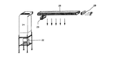
図面を参照すると、各符号は、いくつかの図を通して同じ部分を引用している。図1は、ビニール、あるいはその他の好ましい材料でできたデバイダ10を示しており、このデバイダは、ルームの内側上端および側面にあるループ14またはフープ12に適合するフック12およびループ14を具える外側上端及び側面を有している。このような連結は、フック・アンド・ループ締結具として公知であり、このブランドのひとつはベルクロ(VELCRO:登録商標)である。このデバイダには、デバイダの材質と同じかあるいは異なる材質でできた適合するストリップ18を有するドア16が設けられている。ドア16は、様々なセクションによってわずかに空気が漏れるように構成されている。デバイダには、一又はそれ以上のカラー20が設けられており、このカラーは上側表面近傍においてデバイダを連通している。各々のカラーには、デバイダの両側で、カラーの外側及び/又は内側表面の周囲を取り巻くフック12とループ14が設けられている。これらのフックあるいはループは、ブロアダクトの連結端部のループあるいはフックと、及び、ループあるいはフックを結合させることによってこれらのカラーに固定されるフローダクトの一端にあるループあるいはフックと結合する。ブロアダクトとフローダクトの連結端には、カラーの外側あるいは内側表面上のループあるいはフックに適合するフックあるいはループのいずれかを、外側あるいは内側表面上に有する。一方の表面のフックが、対向する表面のループに適合すること、あるいはその逆は、当業者には明らかである。
DETAILED DESCRIPTION OF THE INVENTION Referring to the drawings, each reference numeral refers to the same part throughout the several views. FIG. 1 shows a
図2及び図3は、図示しないHEPAフィルタを有するブロア22を示す図であり、このブロアは、デバイダ10のブロア側のカラー20の一方の端部に連結されているダクト24を介して清浄な空気を導入する。この空気は、カラーを介してデバイダの反対側の空気流ダクト26内に吹き込まれる。この空気流ダクトは、一端がデバイダの清浄エア正圧側のカラーに連結されている。このダクト26には、それを介して空気が図2、3および4に矢印で示すように下側に向けてルーム内に導入されるダクトの底面に、間隔をあけて配置された開口(図示せず)が設けられている。カラーに連結されたフローダクト26の端部には、カラー上のフックあるいはループに結合するループあるいはフックが設けられている。図3及び4に示すように、フローダクト26の端部は、カラーの外側表面に連結されている。カラーに連結されていない方のダクトの端部は、蓋で閉じておくか(図示せず)、あるいは図に示すように空気が流通する開口28を設けておいてもよい。
2 and 3 show a
図2に示すように、フローダクト26には、ダクト26の底面に沿って広げられた場合に、ダクト28内の開口を塞ぐ、ビニールかその他のいかなる所望の材質で出来た巻いたシート29が設けられている。図面を簡潔にするために、この巻きシートは図3及び4では示されていない。巻きシートの目的は、図5乃至7の記載において説明する。
As shown in FIG. 2, the
図3は、一基のブロワダクトシステムを用いた清浄空気源を示す図である。図4は、一のブロアで対応できるルームより更に広いルームの空気交換に使用可能な二基のブロアダクトシステムを示す図である。図3においてシステムで使用されていない方のカラーは、エンドピースで塞いで空気がルームから抜けることを防ぐことができる。 FIG. 3 is a diagram showing a clean air source using a single blower duct system. FIG. 4 is a diagram showing two blower duct systems that can be used for air exchange in a room larger than a room that can be handled by one blower. The collar that is not used in the system in FIG. 3 can be blocked with an end piece to prevent air from escaping from the room.
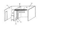
図3、4、6および7に示すように、ルームを完全に囲う側壁は記載されておらず、エア−ブロアシステムのパーツが見えるように省略されている。この囲われたルームは、更に、省略されている側壁に加え、上側壁(天井)を有しており、これも図示されていない。図3及び4に示すように、ブロアを具えるルームは、負圧空間30であり、フローダクト26を具えるルーム32は、正圧空間である。
As shown in FIGS. 3, 4, 6 and 7, the side walls that completely enclose the room are not shown and are omitted so that the parts of the air-blower system can be seen. The enclosed room further includes an upper side wall (ceiling) in addition to the omitted side wall, which is not shown. As shown in FIGS. 3 and 4, the room including the blower is the negative pressure space 30, and the room 32 including the
図2乃至図4に示すシステムでは、研究用の検体は正圧ルームにおく。正圧ルームが負圧ルームに変わるべき例もある。これは、本発明の特徴の一つである。図5乃至7は、正圧ルームを負圧ルームに変える圧力システムを示す図である。 In the system shown in FIGS. 2 to 4, the specimen for research is placed in a positive pressure room. In some cases, the positive pressure room should be changed to a negative pressure room. This is one of the features of the present invention. 5 to 7 are diagrams showing a pressure system for changing a positive pressure room into a negative pressure room.
正圧空間を負圧空間に変えるべき場合が生じたら、ブロアとブロアダクトを大気圧空間から検体がおかれている空間(元の正圧空間)に移動させる。ブロアとブロアダクトを移動させた後に、フローダクト26の出口端をブロアダクトの出口端に接続させて、その結果フローダクト26の出口端がダクトの入口端になるようにする。ダクトの元の入口端は、カラー20にそのまま連結しておき、ここで負圧のフローダクトの出口端にする。現正圧空間に延在するカラーの反対側の端部は、負圧空間の出口になる。
When there is a case where the positive pressure space should be changed to the negative pressure space, the blower and the blower duct are moved from the atmospheric pressure space to the space where the specimen is placed (original positive pressure space). After moving the blower and the blower duct, the outlet end of the
図5乃至7に示すとおり、正圧空間用に用いた同じ装置が、正圧空間を負圧空間に変えるのに使用される。この変更には、ブロア22とブロアダクト24を検体室に移動させ、ブロアダクトの出口端を、ここで空気取り入れ口となる、元のフローダクトの出口端に連結することが必要である。カラーに連結されていたフローダクト端部は、カラーに連結したままにしておく。従って、正圧空間を負圧空間に変えるのに唯一必要なことは、ブロアダクトの出口端を検体室に隣接したルーム内のカラーの端部から切り離して、ブロア22とブロアダクト24を検体室に移動させて、ブロアダクトの出口端をフローダクトの前の出口端に連結することである。フローダクトの元の出口端は、ここでフローダクトの取り入れ口になる。フローダクトの反対側の端部は、カラーに連結されたままにするので、フローダクトとカラーの連結において変更はない。
As shown in FIGS. 5-7, the same device used for the positive pressure space is used to change the positive pressure space into a negative pressure space. This change requires moving the
フローダクト26を正圧のフローから負圧のフローに変える場合に、フローダクトの長さに沿って下側面に設けた出口開口は、正圧フローダクトの入口端部に固定されている巻きシート29によって覆われる。巻きシートとフローダクトの下側面には、ベロクロ(VELCRO:登録商標)などの適合するループとホックが設けられている。巻きシートは広げられ、負の空気流がルーム内に吹き戻されるのを防ぐために、フローダクトの下側面間に固定される。したがって、正圧ルームを、容易かつ迅速に負圧空間に変えることができる。迅速な変更が、検体室内の検体の汚染を防ぐために必要である。
When changing the
正圧用のカラーとブロアダクトとの連結部、又は、負圧用のフローダクト端とブロアダクトとの連結部における円滑な空気の流通を確実なものにするために、ブロアダクトの端部は、カラーの連結端部あるいはフローダクトの端部にぴったり合致する必要がある。フローダクトの端部は、正圧用および負圧用にカラーの外側表面に連結することができる。したがって、この連結は、正圧と負圧の双方に使用することができる。当業者は、必要であれば、フローダクトの端部をカラーの端部内に嵌めることができる。しかしながら、その場合、正圧空間から負圧空間に移動させる際に更なる変更を必要とする。 In order to ensure smooth air flow at the connecting portion between the positive pressure collar and the blower duct, or between the negative pressure flow duct end and the blower duct, the end of the blower duct is connected to the connecting end of the collar. Must fit snugly to the end of the part or flow duct. The end of the flow duct can be connected to the outer surface of the collar for positive and negative pressure. Therefore, this connection can be used for both positive and negative pressure. One skilled in the art can fit the end of the flow duct into the end of the collar if desired. In that case, however, further changes are required when moving from the positive pressure space to the negative pressure space.
説明は、正圧空間から負圧空間への変更についてなされているが、負圧空間から正圧空間への逆の変更も可能である。このような変更は、上述の工程と逆の工程を必要とする。 The description is made on the change from the positive pressure space to the negative pressure space, but the reverse change from the negative pressure space to the positive pressure space is also possible. Such a change requires the reverse process of the above-mentioned process.
上記の説明は、本発明の好ましい実施例に関してなされたものであるが、本発明の精神および範囲内で、これらの他の変形あるいは他の実施例が可能であり、本発明の範囲は特許請求の範囲によって規定される。 While the above description has been made with reference to preferred embodiments of the invention, other modifications and other embodiments are possible within the spirit and scope of the invention, and the scope of the invention is claimed. Specified by the scope of
Claims (12)
前記ルームを少なくとも一つの第1の空間と、少なくとも一つの第2の空間に隔離する、前記ルームにおいて移動可能な少なくとも一つのルームデバイダ(10)と、
前記少なくとも一つのルームデバイダの各々に設けた少なくとも一つの開口と、
前記少なくとも一つの開口に設けたカラー(20)であって、前記少なくとも一つの第1の空間から前記少なくとも一つの第2の空間へ延在するカラーと、
前記少なくとも一つの第2の空間に延在する前記各カラー(20)の端部に連結されているフローダクト(26)と、
前記フローダクトの底面に設けた少なくとも一つの空気流開口と、
前記少なくとも一つの空気流開口を塞ぐカバー手段(29)であって、
前記少なくとも一つの空気流開口を覆い塞ぐために、前記フローダクト(26)の底面に前記カバー手段を開放可能に固定する手段を具えるカバー手段と、
ブロア(22)と、
前記ブロアの出力端と前記第1の空間の前記カラーの端部に連結されるか、または、前記少なくとも一つの第2の空間内の前記フローダクトの一方の端部に連結されたブロアダクト(24)と、
を具えることを特徴とするシステム。In a system that selectively generates positive or negative pressure in selected areas of a room space,
At least one room divider (10) movable in the room that separates the room into at least one first space and at least one second space;
At least one opening provided in each of the at least one room divider;
A collar (20) provided in the at least one opening, the collar extending from the at least one first space to the at least one second space;
A flow duct (26) connected to an end of each collar (20) extending into the at least one second space;
At least one air flow opening provided in a bottom surface of the flow duct;
Cover means (29) for closing the at least one air flow opening,
Cover means comprising means for releasably securing the cover means to the bottom surface of the flow duct (26) to cover the at least one air flow opening;
Blower (22),
A blower duct (24) connected to an output end of the blower and an end of the collar in the first space, or connected to one end of the flow duct in the at least one second space. )When,
A system characterized by comprising.
前記ブロアダクトの出口端が、前記カラーのループあるいはフックに結合するループあるいはフックを具え、The outlet end of the blower duct comprises a loop or hook coupled to the collar loop or hook;
前記フローダクトの一方の端部が、前記第2の空間内に延在する前記カラーの一方の端部のループあるいはフックに結合するループあるいはフックを具えることを特徴とするシステム。A system wherein one end of the flow duct comprises a loop or hook that couples to a loop or hook at one end of the collar extending into the second space.
前記ブロアダクト(24)の出口端が、前記カラーのループあるいはフックに結合するループあるいはフックを具え、The outlet end of the blower duct (24) comprises a loop or hook coupled to the collar loop or hook;
前記フローダクト(26)の一の出口端が、前記第2の空間内に延在する前記カラーの一方の端部に設けたループあるいはフックに結合するループあるいはフックを具えることを特徴とするシステム。One outlet end of the flow duct (26) comprises a loop or hook coupled to a loop or hook provided at one end of the collar extending into the second space. system.
Applications Claiming Priority (2)
| Application Number | Priority Date | Filing Date | Title |
|---|---|---|---|
| US10/153,722 US6602128B1 (en) | 2002-05-24 | 2002-05-24 | Clean air room with a blower including a HEPA filter and ducts |
| PCT/US2003/016422 WO2003100324A2 (en) | 2002-05-24 | 2003-05-23 | A clean room with a blower including a hepa filter and ducts |
Publications (2)
| Publication Number | Publication Date |
|---|---|
| JP2005527774A JP2005527774A (en) | 2005-09-15 |
| JP4340228B2 true JP4340228B2 (en) | 2009-10-07 |
Family
ID=27622896
Family Applications (1)
| Application Number | Title | Priority Date | Filing Date |
|---|---|---|---|
| JP2004507741A Expired - Lifetime JP4340228B2 (en) | 2002-05-24 | 2003-05-23 | Clean room with blower with HEPA filter and duct |
Country Status (11)
| Country | Link |
|---|---|
| US (1) | US6602128B1 (en) |
| EP (1) | EP1511962B1 (en) |
| JP (1) | JP4340228B2 (en) |
| AT (1) | ATE330186T1 (en) |
| AU (1) | AU2003228258B2 (en) |
| CA (1) | CA2486205C (en) |
| DE (1) | DE60306157T2 (en) |
| DK (1) | DK1511962T3 (en) |
| ES (1) | ES2266818T3 (en) |
| NZ (1) | NZ536572A (en) |
| WO (1) | WO2003100324A2 (en) |
Families Citing this family (17)
| Publication number | Priority date | Publication date | Assignee | Title |
|---|---|---|---|---|
| CN1553195B (en) * | 2003-08-18 | 2010-04-28 | 南京大学 | Clean chamber for trace element and isotope analysis |
| TW200717689A (en) * | 2005-09-14 | 2007-05-01 | Applied Materials Inc | Methods and apparatus for a band to band transfer module |
| US7462213B2 (en) * | 2005-10-26 | 2008-12-09 | Spengler Charles W | Method of minimizing cross contamination between clean air rooms in a common enclosure |
| US7727299B2 (en) * | 2005-12-08 | 2010-06-01 | Filtration Manufacturing, Inc. | Extended surface pleat air filter |
| DE102007014406B3 (en) * | 2007-03-26 | 2008-04-24 | Airbus Deutschland Gmbh | Supply channel for supplying fresh air and/or air-conditioned air to seat of vehicle i.e. airplane, has air shower designed for sealingly fitting at mantle surface of hollow profile in area of air inlet |
| JP2009002634A (en) * | 2007-06-25 | 2009-01-08 | Unitec Inc | Unit type clean room |
| EP2382514B1 (en) | 2008-12-23 | 2018-10-17 | Xoma (Us) Llc | Flexible manufacturing system |
| ES2665972T3 (en) | 2009-08-16 | 2018-04-30 | G-Con Manufacturing Inc. | Modular autonomous mobile white room |
| US9795957B2 (en) * | 2009-08-16 | 2017-10-24 | G-Con Manufacturing, Inc. | Modular, self-contained, mobile clean room |
| US8419837B2 (en) * | 2010-03-09 | 2013-04-16 | Huntair, Inc. | Air filtration system with quick connect |
| US20130344795A1 (en) * | 2012-06-25 | 2013-12-26 | Huntair, Inc. | System and method for delivering air through a boom assembly |
| CN107781938A (en) * | 2016-08-24 | 2018-03-09 | 天津海天方圆节能技术有限公司 | A kind of preparation method of energy-conserving and environment-protective wind-exchanging system |
| AU2020329233B2 (en) | 2019-08-15 | 2022-07-07 | G-Con Manufacturing, Inc. | Removable panel roof for modular, self-contained, mobile clean room |
| US20210316243A1 (en) | 2020-04-13 | 2021-10-14 | Carrier Corporation | Negative air filtration system |
| EP4185757A1 (en) * | 2020-07-23 | 2023-05-31 | Fero International Inc. | Improvements in and relating to mobile medical units |
| US11492795B2 (en) | 2020-08-31 | 2022-11-08 | G-Con Manufacturing, Inc. | Ballroom-style cleanroom assembled from modular buildings |
| JP7018118B1 (en) | 2020-12-31 | 2022-02-09 | 那須 正和 | Sheet-shaped purifying air inducer |
Family Cites Families (18)
| Publication number | Priority date | Publication date | Assignee | Title |
|---|---|---|---|---|
| US673393A (en) * | 1901-01-19 | 1901-05-07 | Albert Gans | Drying and ventilating apparatus. |
| US1597588A (en) * | 1924-07-15 | 1926-08-24 | Earl L Fairbanks | Ventilating and cooling system |
| US3363532A (en) * | 1965-12-01 | 1968-01-16 | James P. Horneff | Gas-circulating means |
| US3505989A (en) * | 1967-05-29 | 1970-04-14 | Johnson & Johnson | Controlled environmental apparatus |
| US3601031A (en) * | 1969-09-22 | 1971-08-24 | Litton Systems Inc | Patient isolator room |
| US3899823A (en) * | 1970-01-12 | 1975-08-19 | Wehr Corp | Air conduit and diffuser assembly |
| US3824909A (en) * | 1970-04-08 | 1974-07-23 | Cgt Corp | Distribution system for clean rooms |
| US4250800A (en) * | 1975-04-09 | 1981-02-17 | Schmidt-Reuter Ingenieurgesellschaft Mbh & Co. Kg | Outlet tube for air conditioning systems |
| DE3261207D1 (en) * | 1981-11-10 | 1984-12-13 | Howorth Air Eng Ltd | Sterile air trolley |
| US4706551A (en) * | 1984-09-20 | 1987-11-17 | Schofield Paul S | Enclosure |
| US4608066A (en) * | 1985-07-31 | 1986-08-26 | Flanders Filters, Inc. | Clean room adapted for variable work area configurations |
| US5645480A (en) * | 1995-05-01 | 1997-07-08 | Spengler; Charles W. | Clean air facility |
| US5725426A (en) * | 1995-12-26 | 1998-03-10 | Alvarez; Henry | Portable and disposable sterilized operating environment |
| ATE346672T1 (en) * | 1997-02-18 | 2006-12-15 | David J Korman | PERSONAL AIR FILTERING AND AIR SUPPLY SYSTEMS |
| JPH11344243A (en) * | 1998-06-03 | 1999-12-14 | Oki Electric Ind Co Ltd | Air shower apparatus |
| US6117005A (en) * | 1998-12-03 | 2000-09-12 | Weiss; Peter T. | Air conditioning extender system |
| US6280320B1 (en) * | 1999-07-13 | 2001-08-28 | Rite-Hite Holding Corporation | Frame to support a deflated fabric air duct |
| JP3476395B2 (en) * | 1999-09-24 | 2003-12-10 | Necエレクトロニクス株式会社 | Clean room and clean room air conditioning method |
-
2002
- 2002-05-24 US US10/153,722 patent/US6602128B1/en not_active Expired - Lifetime
-
2003
- 2003-05-23 CA CA002486205A patent/CA2486205C/en not_active Expired - Fee Related
- 2003-05-23 DE DE60306157T patent/DE60306157T2/en not_active Expired - Lifetime
- 2003-05-23 ES ES03726957T patent/ES2266818T3/en not_active Expired - Lifetime
- 2003-05-23 AU AU2003228258A patent/AU2003228258B2/en not_active Ceased
- 2003-05-23 EP EP03726957A patent/EP1511962B1/en not_active Expired - Lifetime
- 2003-05-23 NZ NZ536572A patent/NZ536572A/en not_active IP Right Cessation
- 2003-05-23 AT AT03726957T patent/ATE330186T1/en active
- 2003-05-23 DK DK03726957T patent/DK1511962T3/en active
- 2003-05-23 JP JP2004507741A patent/JP4340228B2/en not_active Expired - Lifetime
- 2003-05-23 WO PCT/US2003/016422 patent/WO2003100324A2/en active IP Right Grant
Also Published As
| Publication number | Publication date |
|---|---|
| DK1511962T3 (en) | 2006-09-04 |
| US6602128B1 (en) | 2003-08-05 |
| DE60306157T2 (en) | 2007-05-10 |
| ATE330186T1 (en) | 2006-07-15 |
| ES2266818T3 (en) | 2007-03-01 |
| JP2005527774A (en) | 2005-09-15 |
| WO2003100324A3 (en) | 2004-04-29 |
| CA2486205A1 (en) | 2003-12-04 |
| AU2003228258A1 (en) | 2003-12-12 |
| AU2003228258B2 (en) | 2008-01-03 |
| DE60306157D1 (en) | 2006-07-27 |
| EP1511962B1 (en) | 2006-06-14 |
| EP1511962A2 (en) | 2005-03-09 |
| NZ536572A (en) | 2006-06-30 |
| CA2486205C (en) | 2008-09-30 |
| WO2003100324A2 (en) | 2003-12-04 |
Similar Documents
| Publication | Publication Date | Title |
|---|---|---|
| JP4340228B2 (en) | Clean room with blower with HEPA filter and duct | |
| JP3911904B2 (en) | Clean room structure | |
| US5645480A (en) | Clean air facility | |
| US20050287945A1 (en) | Ventilating system | |
| US20060199509A1 (en) | Ventilating system | |
| KR20080083942A (en) | A ventilation system for heat exchange | |
| JPH10339488A (en) | Ventilation device | |
| JP4071155B2 (en) | Equipment for removing harmful chemical substances such as formaldehyde | |
| JP3913663B2 (en) | Bathroom heater ventilator | |
| KR102495191B1 (en) | Residential indoor environment complex control device using total heat exchanger | |
| JPH116643A (en) | Residential ventilator and ventilation system | |
| KR102041751B1 (en) | Apparatus and Method for Cleaning Return Duct | |
| JPH0466034A (en) | Apparatus for raising animal | |
| JP2014145570A (en) | Ventilation device | |
| JP2008032319A (en) | Heat exchange type ventilating device, ventilation system and building | |
| JP2004205100A (en) | Air conditioner | |
| JP3521764B2 (en) | Clean room ceiling structure | |
| KR20080083938A (en) | A ventilation system for heat exchange | |
| JP6203240B2 (en) | Heat exchanger and ventilator | |
| JPH1037331A (en) | Ventilation structure for residential building | |
| JPH0721209Y2 (en) | Filter duct unit for clean room | |
| JP3736323B2 (en) | Clean room ceiling structure | |
| JPS5939888Y2 (en) | Laboratory animal breeding equipment | |
| IT202000006391A1 (en) | Ceiling speaker | |
| JP2002039590A (en) | Ventilator |
Legal Events
| Date | Code | Title | Description |
|---|---|---|---|
| A621 | Written request for application examination |
Free format text: JAPANESE INTERMEDIATE CODE: A621 Effective date: 20060510 |
|
| A131 | Notification of reasons for refusal |
Free format text: JAPANESE INTERMEDIATE CODE: A131 Effective date: 20081111 |
|
| A521 | Request for written amendment filed |
Free format text: JAPANESE INTERMEDIATE CODE: A523 Effective date: 20090209 |
|
| TRDD | Decision of grant or rejection written | ||
| A01 | Written decision to grant a patent or to grant a registration (utility model) |
Free format text: JAPANESE INTERMEDIATE CODE: A01 Effective date: 20090616 |
|
| A01 | Written decision to grant a patent or to grant a registration (utility model) |
Free format text: JAPANESE INTERMEDIATE CODE: A01 |
|
| A61 | First payment of annual fees (during grant procedure) |
Free format text: JAPANESE INTERMEDIATE CODE: A61 Effective date: 20090703 |
|
| R150 | Certificate of patent or registration of utility model |
Ref document number: 4340228 Country of ref document: JP Free format text: JAPANESE INTERMEDIATE CODE: R150 Free format text: JAPANESE INTERMEDIATE CODE: R150 |
|
| FPAY | Renewal fee payment (event date is renewal date of database) |
Free format text: PAYMENT UNTIL: 20120710 Year of fee payment: 3 |
|
| FPAY | Renewal fee payment (event date is renewal date of database) |
Free format text: PAYMENT UNTIL: 20130710 Year of fee payment: 4 |
|
| R250 | Receipt of annual fees |
Free format text: JAPANESE INTERMEDIATE CODE: R250 |
|
| R250 | Receipt of annual fees |
Free format text: JAPANESE INTERMEDIATE CODE: R250 |
|
| R250 | Receipt of annual fees |
Free format text: JAPANESE INTERMEDIATE CODE: R250 |
|
| R250 | Receipt of annual fees |
Free format text: JAPANESE INTERMEDIATE CODE: R250 |
|
| R250 | Receipt of annual fees |
Free format text: JAPANESE INTERMEDIATE CODE: R250 |
|
| R250 | Receipt of annual fees |
Free format text: JAPANESE INTERMEDIATE CODE: R250 |
|
| R250 | Receipt of annual fees |
Free format text: JAPANESE INTERMEDIATE CODE: R250 |
|
| R250 | Receipt of annual fees |
Free format text: JAPANESE INTERMEDIATE CODE: R250 |
|
| R250 | Receipt of annual fees |
Free format text: JAPANESE INTERMEDIATE CODE: R250 |
|
| R250 | Receipt of annual fees |
Free format text: JAPANESE INTERMEDIATE CODE: R250 |
|
| EXPY | Cancellation because of completion of term |