JP4335017B2 - Thermoreversible recording medium, thermoreversible recording member, and image processing method - Google Patents
Thermoreversible recording medium, thermoreversible recording member, and image processing method Download PDFInfo
- Publication number
- JP4335017B2 JP4335017B2 JP2004002942A JP2004002942A JP4335017B2 JP 4335017 B2 JP4335017 B2 JP 4335017B2 JP 2004002942 A JP2004002942 A JP 2004002942A JP 2004002942 A JP2004002942 A JP 2004002942A JP 4335017 B2 JP4335017 B2 JP 4335017B2
- Authority
- JP
- Japan
- Prior art keywords
- thermoreversible recording
- recording medium
- layer
- heat
- resin
- Prior art date
- Legal status (The legal status is an assumption and is not a legal conclusion. Google has not performed a legal analysis and makes no representation as to the accuracy of the status listed.)
- Expired - Lifetime
Links
- 238000003672 processing method Methods 0.000 title claims description 21
- 239000010410 layer Substances 0.000 claims abstract description 405
- 239000011241 protective layer Substances 0.000 claims abstract description 82
- 239000011231 conductive filler Substances 0.000 claims abstract description 45
- 238000010438 heat treatment Methods 0.000 claims abstract description 35
- 229920005989 resin Polymers 0.000 claims description 119
- 239000011347 resin Substances 0.000 claims description 119
- -1 phenol compound Chemical class 0.000 claims description 37
- 230000002441 reversible effect Effects 0.000 claims description 37
- 150000001875 compounds Chemical class 0.000 claims description 36
- 239000011230 binding agent Substances 0.000 claims description 31
- GWEVSGVZZGPLCZ-UHFFFAOYSA-N Titan oxide Chemical group O=[Ti]=O GWEVSGVZZGPLCZ-UHFFFAOYSA-N 0.000 claims description 30
- OGIDPMRJRNCKJF-UHFFFAOYSA-N titanium oxide Inorganic materials [Ti]=O OGIDPMRJRNCKJF-UHFFFAOYSA-N 0.000 claims description 30
- 238000003860 storage Methods 0.000 claims description 29
- 239000000919 ceramic Substances 0.000 claims description 23
- 229920001187 thermosetting polymer Polymers 0.000 claims description 19
- XOLBLPGZBRYERU-UHFFFAOYSA-N tin dioxide Chemical compound O=[Sn]=O XOLBLPGZBRYERU-UHFFFAOYSA-N 0.000 claims description 19
- 229910001887 tin oxide Inorganic materials 0.000 claims description 19
- 125000004432 carbon atom Chemical group C* 0.000 claims description 11
- 230000003287 optical effect Effects 0.000 claims description 10
- 239000013078 crystal Substances 0.000 claims description 8
- 239000006097 ultraviolet radiation absorber Substances 0.000 claims description 7
- 239000006258 conductive agent Substances 0.000 claims description 6
- 125000000217 alkyl group Chemical group 0.000 claims description 5
- 238000007639 printing Methods 0.000 abstract description 47
- 238000000576 coating method Methods 0.000 description 90
- 239000011248 coating agent Substances 0.000 description 87
- KFZMGEQAYNKOFK-UHFFFAOYSA-N Isopropanol Chemical compound CC(C)O KFZMGEQAYNKOFK-UHFFFAOYSA-N 0.000 description 46
- 238000000034 method Methods 0.000 description 44
- 238000012545 processing Methods 0.000 description 43
- ZWEHNKRNPOVVGH-UHFFFAOYSA-N 2-Butanone Chemical compound CCC(C)=O ZWEHNKRNPOVVGH-UHFFFAOYSA-N 0.000 description 30
- 239000000203 mixture Substances 0.000 description 26
- 239000000123 paper Substances 0.000 description 24
- VYPSYNLAJGMNEJ-UHFFFAOYSA-N silicon dioxide Inorganic materials O=[Si]=O VYPSYNLAJGMNEJ-UHFFFAOYSA-N 0.000 description 22
- 238000001723 curing Methods 0.000 description 19
- 239000007788 liquid Substances 0.000 description 19
- 238000004519 manufacturing process Methods 0.000 description 19
- 239000003999 initiator Substances 0.000 description 18
- 238000002360 preparation method Methods 0.000 description 18
- 230000000052 comparative effect Effects 0.000 description 17
- 238000004132 cross linking Methods 0.000 description 17
- 239000000463 material Substances 0.000 description 17
- 239000000945 filler Substances 0.000 description 16
- 230000000670 limiting effect Effects 0.000 description 16
- 230000003068 static effect Effects 0.000 description 16
- YXFVVABEGXRONW-UHFFFAOYSA-N Toluene Chemical compound CC1=CC=CC=C1 YXFVVABEGXRONW-UHFFFAOYSA-N 0.000 description 15
- 239000002904 solvent Substances 0.000 description 15
- 239000012790 adhesive layer Substances 0.000 description 14
- 238000001035 drying Methods 0.000 description 14
- 239000000975 dye Substances 0.000 description 14
- 239000000178 monomer Substances 0.000 description 14
- MPIAGWXWVAHQBB-UHFFFAOYSA-N [3-prop-2-enoyloxy-2-[[3-prop-2-enoyloxy-2,2-bis(prop-2-enoyloxymethyl)propoxy]methyl]-2-(prop-2-enoyloxymethyl)propyl] prop-2-enoate Chemical compound C=CC(=O)OCC(COC(=O)C=C)(COC(=O)C=C)COCC(COC(=O)C=C)(COC(=O)C=C)COC(=O)C=C MPIAGWXWVAHQBB-UHFFFAOYSA-N 0.000 description 13
- 238000010586 diagram Methods 0.000 description 13
- 238000010894 electron beam technology Methods 0.000 description 13
- 239000012948 isocyanate Substances 0.000 description 13
- 230000008569 process Effects 0.000 description 13
- 230000000694 effects Effects 0.000 description 12
- QNODIIQQMGDSEF-UHFFFAOYSA-N (1-hydroxycyclohexyl)-phenylmethanone Chemical compound C=1C=CC=CC=1C(=O)C1(O)CCCCC1 QNODIIQQMGDSEF-UHFFFAOYSA-N 0.000 description 11
- 230000008859 change Effects 0.000 description 11
- UHESRSKEBRADOO-UHFFFAOYSA-N ethyl carbamate;prop-2-enoic acid Chemical compound OC(=O)C=C.CCOC(N)=O UHESRSKEBRADOO-UHFFFAOYSA-N 0.000 description 11
- 150000002513 isocyanates Chemical class 0.000 description 11
- 239000002245 particle Substances 0.000 description 11
- 229920005862 polyol Polymers 0.000 description 11
- 239000000758 substrate Substances 0.000 description 11
- XLOMVQKBTHCTTD-UHFFFAOYSA-N Zinc monoxide Chemical compound [Zn]=O XLOMVQKBTHCTTD-UHFFFAOYSA-N 0.000 description 10
- 230000006870 function Effects 0.000 description 10
- 125000002887 hydroxy group Chemical group [H]O* 0.000 description 10
- 239000004820 Pressure-sensitive adhesive Substances 0.000 description 9
- 230000015572 biosynthetic process Effects 0.000 description 9
- 239000003431 cross linking reagent Substances 0.000 description 9
- 239000000428 dust Substances 0.000 description 9
- 230000005611 electricity Effects 0.000 description 9
- 239000000049 pigment Substances 0.000 description 9
- 229920002635 polyurethane Polymers 0.000 description 9
- 239000000377 silicon dioxide Substances 0.000 description 9
- 238000012360 testing method Methods 0.000 description 9
- WNZQDUSMALZDQF-UHFFFAOYSA-N 2-benzofuran-1(3H)-one Chemical compound C1=CC=C2C(=O)OCC2=C1 WNZQDUSMALZDQF-UHFFFAOYSA-N 0.000 description 8
- LFQSCWFLJHTTHZ-UHFFFAOYSA-N Ethanol Chemical compound CCO LFQSCWFLJHTTHZ-UHFFFAOYSA-N 0.000 description 7
- 239000003795 chemical substances by application Substances 0.000 description 7
- 238000004040 coloring Methods 0.000 description 7
- 230000002829 reductive effect Effects 0.000 description 7
- 238000000926 separation method Methods 0.000 description 7
- XEKOWRVHYACXOJ-UHFFFAOYSA-N Ethyl acetate Chemical compound CCOC(C)=O XEKOWRVHYACXOJ-UHFFFAOYSA-N 0.000 description 6
- OWYWGLHRNBIFJP-UHFFFAOYSA-N Ipazine Chemical compound CCN(CC)C1=NC(Cl)=NC(NC(C)C)=N1 OWYWGLHRNBIFJP-UHFFFAOYSA-N 0.000 description 6
- 229920000297 Rayon Polymers 0.000 description 6
- WYURNTSHIVDZCO-UHFFFAOYSA-N Tetrahydrofuran Chemical compound C1CCOC1 WYURNTSHIVDZCO-UHFFFAOYSA-N 0.000 description 6
- 125000001931 aliphatic group Chemical group 0.000 description 6
- 239000006185 dispersion Substances 0.000 description 6
- 229920000178 Acrylic resin Polymers 0.000 description 5
- 239000004925 Acrylic resin Substances 0.000 description 5
- 238000011156 evaluation Methods 0.000 description 5
- 238000002156 mixing Methods 0.000 description 5
- 239000004014 plasticizer Substances 0.000 description 5
- 230000001681 protective effect Effects 0.000 description 5
- 239000011787 zinc oxide Substances 0.000 description 5
- GKZPEYIPJQHPNC-UHFFFAOYSA-N 2,2-bis(hydroxymethyl)propane-1,3-diol prop-2-enoic acid Chemical compound OC(=O)C=C.OC(=O)C=C.OC(=O)C=C.OC(=O)C=C.OC(=O)C=C.OC(=O)C=C.OCC(CO)(CO)CO GKZPEYIPJQHPNC-UHFFFAOYSA-N 0.000 description 4
- TXBCBTDQIULDIA-UHFFFAOYSA-N 2-[[3-hydroxy-2,2-bis(hydroxymethyl)propoxy]methyl]-2-(hydroxymethyl)propane-1,3-diol Chemical compound OCC(CO)(CO)COCC(CO)(CO)CO TXBCBTDQIULDIA-UHFFFAOYSA-N 0.000 description 4
- VTYYLEPIZMXCLO-UHFFFAOYSA-L Calcium carbonate Chemical compound [Ca+2].[O-]C([O-])=O VTYYLEPIZMXCLO-UHFFFAOYSA-L 0.000 description 4
- UQSXHKLRYXJYBZ-UHFFFAOYSA-N Iron oxide Chemical compound [Fe]=O UQSXHKLRYXJYBZ-UHFFFAOYSA-N 0.000 description 4
- LRHPLDYGYMQRHN-UHFFFAOYSA-N N-Butanol Chemical compound CCCCO LRHPLDYGYMQRHN-UHFFFAOYSA-N 0.000 description 4
- 239000004677 Nylon Substances 0.000 description 4
- ISWSIDIOOBJBQZ-UHFFFAOYSA-N Phenol Natural products OC1=CC=CC=C1 ISWSIDIOOBJBQZ-UHFFFAOYSA-N 0.000 description 4
- PPBRXRYQALVLMV-UHFFFAOYSA-N Styrene Chemical compound C=CC1=CC=CC=C1 PPBRXRYQALVLMV-UHFFFAOYSA-N 0.000 description 4
- 238000010521 absorption reaction Methods 0.000 description 4
- PNEYBMLMFCGWSK-UHFFFAOYSA-N aluminium oxide Inorganic materials [O-2].[O-2].[O-2].[Al+3].[Al+3] PNEYBMLMFCGWSK-UHFFFAOYSA-N 0.000 description 4
- QVQLCTNNEUAWMS-UHFFFAOYSA-N barium oxide Chemical compound [Ba]=O QVQLCTNNEUAWMS-UHFFFAOYSA-N 0.000 description 4
- TZCXTZWJZNENPQ-UHFFFAOYSA-L barium sulfate Chemical compound [Ba+2].[O-]S([O-])(=O)=O TZCXTZWJZNENPQ-UHFFFAOYSA-L 0.000 description 4
- 238000006243 chemical reaction Methods 0.000 description 4
- 239000003086 colorant Substances 0.000 description 4
- JHIVVAPYMSGYDF-UHFFFAOYSA-N cyclohexanone Chemical compound O=C1CCCCC1 JHIVVAPYMSGYDF-UHFFFAOYSA-N 0.000 description 4
- 238000013461 design Methods 0.000 description 4
- 238000011161 development Methods 0.000 description 4
- LYCAIKOWRPUZTN-UHFFFAOYSA-N ethylene glycol Natural products OCCO LYCAIKOWRPUZTN-UHFFFAOYSA-N 0.000 description 4
- 125000000524 functional group Chemical group 0.000 description 4
- 229920006015 heat resistant resin Polymers 0.000 description 4
- 150000002430 hydrocarbons Chemical group 0.000 description 4
- 229910000040 hydrogen fluoride Inorganic materials 0.000 description 4
- 239000001023 inorganic pigment Substances 0.000 description 4
- 239000000314 lubricant Substances 0.000 description 4
- 229910052751 metal Inorganic materials 0.000 description 4
- 239000002184 metal Substances 0.000 description 4
- 229910044991 metal oxide Inorganic materials 0.000 description 4
- 229920001778 nylon Polymers 0.000 description 4
- 239000005011 phenolic resin Substances 0.000 description 4
- 239000000843 powder Substances 0.000 description 4
- 230000002265 prevention Effects 0.000 description 4
- 239000004094 surface-active agent Substances 0.000 description 4
- XLYOFNOQVPJJNP-UHFFFAOYSA-N water Substances O XLYOFNOQVPJJNP-UHFFFAOYSA-N 0.000 description 4
- VBZYPJAXRLNOCG-UHFFFAOYSA-N 2-[[3-hydroxy-2,2-bis(hydroxymethyl)propoxy]methyl]-2-(hydroxymethyl)propane-1,3-diol;oxepan-2-one Chemical compound O=C1CCCCCO1.OCC(CO)(CO)COCC(CO)(CO)CO VBZYPJAXRLNOCG-UHFFFAOYSA-N 0.000 description 3
- QTBSBXVTEAMEQO-UHFFFAOYSA-N Acetic acid Chemical compound CC(O)=O QTBSBXVTEAMEQO-UHFFFAOYSA-N 0.000 description 3
- CSCPPACGZOOCGX-UHFFFAOYSA-N Acetone Chemical compound CC(C)=O CSCPPACGZOOCGX-UHFFFAOYSA-N 0.000 description 3
- UHOVQNZJYSORNB-UHFFFAOYSA-N Benzene Chemical compound C1=CC=CC=C1 UHOVQNZJYSORNB-UHFFFAOYSA-N 0.000 description 3
- OKTJSMMVPCPJKN-UHFFFAOYSA-N Carbon Chemical compound [C] OKTJSMMVPCPJKN-UHFFFAOYSA-N 0.000 description 3
- KRHYYFGTRYWZRS-UHFFFAOYSA-N Fluorane Chemical compound F KRHYYFGTRYWZRS-UHFFFAOYSA-N 0.000 description 3
- WSFSSNUMVMOOMR-UHFFFAOYSA-N Formaldehyde Chemical compound O=C WSFSSNUMVMOOMR-UHFFFAOYSA-N 0.000 description 3
- OKKJLVBELUTLKV-UHFFFAOYSA-N Methanol Chemical compound OC OKKJLVBELUTLKV-UHFFFAOYSA-N 0.000 description 3
- NTIZESTWPVYFNL-UHFFFAOYSA-N Methyl isobutyl ketone Chemical compound CC(C)CC(C)=O NTIZESTWPVYFNL-UHFFFAOYSA-N 0.000 description 3
- UIHCLUNTQKBZGK-UHFFFAOYSA-N Methyl isobutyl ketone Natural products CCC(C)C(C)=O UIHCLUNTQKBZGK-UHFFFAOYSA-N 0.000 description 3
- ZMXDDKWLCZADIW-UHFFFAOYSA-N N,N-Dimethylformamide Chemical compound CN(C)C=O ZMXDDKWLCZADIW-UHFFFAOYSA-N 0.000 description 3
- BZHJMEDXRYGGRV-UHFFFAOYSA-N Vinyl chloride Chemical compound ClC=C BZHJMEDXRYGGRV-UHFFFAOYSA-N 0.000 description 3
- 239000006096 absorbing agent Substances 0.000 description 3
- 239000000654 additive Substances 0.000 description 3
- 239000002216 antistatic agent Substances 0.000 description 3
- 229910052799 carbon Inorganic materials 0.000 description 3
- 238000007796 conventional method Methods 0.000 description 3
- 238000001816 cooling Methods 0.000 description 3
- 235000014113 dietary fatty acids Nutrition 0.000 description 3
- 239000003822 epoxy resin Substances 0.000 description 3
- 239000000194 fatty acid Substances 0.000 description 3
- 229930195729 fatty acid Natural products 0.000 description 3
- WGCNASOHLSPBMP-UHFFFAOYSA-N hydroxyacetaldehyde Natural products OCC=O WGCNASOHLSPBMP-UHFFFAOYSA-N 0.000 description 3
- 239000011256 inorganic filler Substances 0.000 description 3
- 229910003475 inorganic filler Inorganic materials 0.000 description 3
- 229910010272 inorganic material Inorganic materials 0.000 description 3
- 125000005647 linker group Chemical group 0.000 description 3
- 238000005259 measurement Methods 0.000 description 3
- 150000004706 metal oxides Chemical class 0.000 description 3
- VLKZOEOYAKHREP-UHFFFAOYSA-N n-Hexane Chemical compound CCCCCC VLKZOEOYAKHREP-UHFFFAOYSA-N 0.000 description 3
- 239000012766 organic filler Substances 0.000 description 3
- 229920002037 poly(vinyl butyral) polymer Polymers 0.000 description 3
- 229920000647 polyepoxide Polymers 0.000 description 3
- 229920000728 polyester Polymers 0.000 description 3
- 239000004814 polyurethane Substances 0.000 description 3
- 229920005749 polyurethane resin Polymers 0.000 description 3
- 239000002356 single layer Substances 0.000 description 3
- YLQBMQCUIZJEEH-UHFFFAOYSA-N tetrahydrofuran Natural products C=1C=COC=1 YLQBMQCUIZJEEH-UHFFFAOYSA-N 0.000 description 3
- 125000000391 vinyl group Chemical group [H]C([*])=C([H])[H] 0.000 description 3
- 238000012800 visualization Methods 0.000 description 3
- LIZLYZVAYZQVPG-UHFFFAOYSA-N (3-bromo-2-fluorophenyl)methanol Chemical compound OCC1=CC=CC(Br)=C1F LIZLYZVAYZQVPG-UHFFFAOYSA-N 0.000 description 2
- FKTHNVSLHLHISI-UHFFFAOYSA-N 1,2-bis(isocyanatomethyl)benzene Chemical compound O=C=NCC1=CC=CC=C1CN=C=O FKTHNVSLHLHISI-UHFFFAOYSA-N 0.000 description 2
- OMIGHNLMNHATMP-UHFFFAOYSA-N 2-hydroxyethyl prop-2-enoate Chemical compound OCCOC(=O)C=C OMIGHNLMNHATMP-UHFFFAOYSA-N 0.000 description 2
- VHSHLMUCYSAUQU-UHFFFAOYSA-N 2-hydroxypropyl methacrylate Chemical compound CC(O)COC(=O)C(C)=C VHSHLMUCYSAUQU-UHFFFAOYSA-N 0.000 description 2
- QZPSOSOOLFHYRR-UHFFFAOYSA-N 3-hydroxypropyl prop-2-enoate Chemical compound OCCCOC(=O)C=C QZPSOSOOLFHYRR-UHFFFAOYSA-N 0.000 description 2
- NIXOWILDQLNWCW-UHFFFAOYSA-M Acrylate Chemical compound [O-]C(=O)C=C NIXOWILDQLNWCW-UHFFFAOYSA-M 0.000 description 2
- 239000005995 Aluminium silicate Substances 0.000 description 2
- IJGRMHOSHXDMSA-UHFFFAOYSA-N Atomic nitrogen Chemical compound N#N IJGRMHOSHXDMSA-UHFFFAOYSA-N 0.000 description 2
- DKPFZGUDAPQIHT-UHFFFAOYSA-N Butyl acetate Natural products CCCCOC(C)=O DKPFZGUDAPQIHT-UHFFFAOYSA-N 0.000 description 2
- HEDRZPFGACZZDS-UHFFFAOYSA-N Chloroform Chemical compound ClC(Cl)Cl HEDRZPFGACZZDS-UHFFFAOYSA-N 0.000 description 2
- 229920000742 Cotton Polymers 0.000 description 2
- 229920001651 Cyanoacrylate Polymers 0.000 description 2
- IAZDPXIOMUYVGZ-UHFFFAOYSA-N Dimethylsulphoxide Chemical compound CS(C)=O IAZDPXIOMUYVGZ-UHFFFAOYSA-N 0.000 description 2
- 239000004593 Epoxy Substances 0.000 description 2
- JOYRKODLDBILNP-UHFFFAOYSA-N Ethyl urethane Chemical compound CCOC(N)=O JOYRKODLDBILNP-UHFFFAOYSA-N 0.000 description 2
- PEDCQBHIVMGVHV-UHFFFAOYSA-N Glycerine Chemical compound OCC(O)CO PEDCQBHIVMGVHV-UHFFFAOYSA-N 0.000 description 2
- 239000005057 Hexamethylene diisocyanate Substances 0.000 description 2
- WOBHKFSMXKNTIM-UHFFFAOYSA-N Hydroxyethyl methacrylate Chemical compound CC(=C)C(=O)OCCO WOBHKFSMXKNTIM-UHFFFAOYSA-N 0.000 description 2
- XEEYBQQBJWHFJM-UHFFFAOYSA-N Iron Chemical compound [Fe] XEEYBQQBJWHFJM-UHFFFAOYSA-N 0.000 description 2
- 229920000877 Melamine resin Polymers 0.000 description 2
- 239000004640 Melamine resin Substances 0.000 description 2
- MWCLLHOVUTZFKS-UHFFFAOYSA-N Methyl cyanoacrylate Chemical compound COC(=O)C(=C)C#N MWCLLHOVUTZFKS-UHFFFAOYSA-N 0.000 description 2
- IMNFDUFMRHMDMM-UHFFFAOYSA-N N-Heptane Chemical compound CCCCCCC IMNFDUFMRHMDMM-UHFFFAOYSA-N 0.000 description 2
- CTQNGGLPUBDAKN-UHFFFAOYSA-N O-Xylene Chemical compound CC1=CC=CC=C1C CTQNGGLPUBDAKN-UHFFFAOYSA-N 0.000 description 2
- 229910019142 PO4 Inorganic materials 0.000 description 2
- 239000004793 Polystyrene Substances 0.000 description 2
- XBDQKXXYIPTUBI-UHFFFAOYSA-M Propionate Chemical compound CCC([O-])=O XBDQKXXYIPTUBI-UHFFFAOYSA-M 0.000 description 2
- 229910052581 Si3N4 Inorganic materials 0.000 description 2
- DAKWPKUUDNSNPN-UHFFFAOYSA-N Trimethylolpropane triacrylate Chemical compound C=CC(=O)OCC(CC)(COC(=O)C=C)COC(=O)C=C DAKWPKUUDNSNPN-UHFFFAOYSA-N 0.000 description 2
- 229920001807 Urea-formaldehyde Polymers 0.000 description 2
- MCMNRKCIXSYSNV-UHFFFAOYSA-N Zirconium dioxide Chemical compound O=[Zr]=O MCMNRKCIXSYSNV-UHFFFAOYSA-N 0.000 description 2
- 239000002253 acid Substances 0.000 description 2
- 229920006243 acrylic copolymer Polymers 0.000 description 2
- 239000000853 adhesive Substances 0.000 description 2
- 230000001070 adhesive effect Effects 0.000 description 2
- 238000007754 air knife coating Methods 0.000 description 2
- WNROFYMDJYEPJX-UHFFFAOYSA-K aluminium hydroxide Chemical compound [OH-].[OH-].[OH-].[Al+3] WNROFYMDJYEPJX-UHFFFAOYSA-K 0.000 description 2
- 235000012211 aluminium silicate Nutrition 0.000 description 2
- 150000001408 amides Chemical class 0.000 description 2
- 150000001412 amines Chemical class 0.000 description 2
- 229910052787 antimony Inorganic materials 0.000 description 2
- WATWJIUSRGPENY-UHFFFAOYSA-N antimony atom Chemical compound [Sb] WATWJIUSRGPENY-UHFFFAOYSA-N 0.000 description 2
- 239000011324 bead Substances 0.000 description 2
- RWCCWEUUXYIKHB-UHFFFAOYSA-N benzophenone Chemical compound C=1C=CC=CC=1C(=O)C1=CC=CC=C1 RWCCWEUUXYIKHB-UHFFFAOYSA-N 0.000 description 2
- 239000012965 benzophenone Substances 0.000 description 2
- QRUDEWIWKLJBPS-UHFFFAOYSA-N benzotriazole Chemical compound C1=CC=C2N[N][N]C2=C1 QRUDEWIWKLJBPS-UHFFFAOYSA-N 0.000 description 2
- 239000012964 benzotriazole Substances 0.000 description 2
- 229910000019 calcium carbonate Inorganic materials 0.000 description 2
- 125000003178 carboxy group Chemical group [H]OC(*)=O 0.000 description 2
- 125000002843 carboxylic acid group Chemical group 0.000 description 2
- 229910000420 cerium oxide Inorganic materials 0.000 description 2
- 239000011247 coating layer Substances 0.000 description 2
- 238000004891 communication Methods 0.000 description 2
- 238000007766 curtain coating Methods 0.000 description 2
- 230000007547 defect Effects 0.000 description 2
- 238000006356 dehydrogenation reaction Methods 0.000 description 2
- 238000007607 die coating method Methods 0.000 description 2
- XBDQKXXYIPTUBI-UHFFFAOYSA-N dimethylselenoniopropionate Natural products CCC(O)=O XBDQKXXYIPTUBI-UHFFFAOYSA-N 0.000 description 2
- 238000003618 dip coating Methods 0.000 description 2
- NJLLQSBAHIKGKF-UHFFFAOYSA-N dipotassium dioxido(oxo)titanium Chemical compound [K+].[K+].[O-][Ti]([O-])=O NJLLQSBAHIKGKF-UHFFFAOYSA-N 0.000 description 2
- 239000002270 dispersing agent Substances 0.000 description 2
- 150000002148 esters Chemical class 0.000 description 2
- 239000000835 fiber Substances 0.000 description 2
- 235000013611 frozen food Nutrition 0.000 description 2
- 238000007756 gravure coating Methods 0.000 description 2
- 230000017525 heat dissipation Effects 0.000 description 2
- RRAMGCGOFNQTLD-UHFFFAOYSA-N hexamethylene diisocyanate Chemical compound O=C=NCCCCCCN=C=O RRAMGCGOFNQTLD-UHFFFAOYSA-N 0.000 description 2
- FUZZWVXGSFPDMH-UHFFFAOYSA-N hexanoic acid Chemical compound CCCCCC(O)=O FUZZWVXGSFPDMH-UHFFFAOYSA-N 0.000 description 2
- 239000012943 hotmelt Substances 0.000 description 2
- AMWRITDGCCNYAT-UHFFFAOYSA-L hydroxy(oxo)manganese;manganese Chemical compound [Mn].O[Mn]=O.O[Mn]=O AMWRITDGCCNYAT-UHFFFAOYSA-L 0.000 description 2
- 229910003437 indium oxide Inorganic materials 0.000 description 2
- PJXISJQVUVHSOJ-UHFFFAOYSA-N indium(iii) oxide Chemical compound [O-2].[O-2].[O-2].[In+3].[In+3] PJXISJQVUVHSOJ-UHFFFAOYSA-N 0.000 description 2
- 239000000976 ink Substances 0.000 description 2
- 239000011147 inorganic material Substances 0.000 description 2
- 230000002427 irreversible effect Effects 0.000 description 2
- NLYAJNPCOHFWQQ-UHFFFAOYSA-N kaolin Chemical compound O.O.O=[Al]O[Si](=O)O[Si](=O)O[Al]=O NLYAJNPCOHFWQQ-UHFFFAOYSA-N 0.000 description 2
- 238000007759 kiss coating Methods 0.000 description 2
- 238000010030 laminating Methods 0.000 description 2
- ZLNQQNXFFQJAID-UHFFFAOYSA-L magnesium carbonate Chemical compound [Mg+2].[O-]C([O-])=O ZLNQQNXFFQJAID-UHFFFAOYSA-L 0.000 description 2
- 239000001095 magnesium carbonate Substances 0.000 description 2
- 229910000021 magnesium carbonate Inorganic materials 0.000 description 2
- 239000000395 magnesium oxide Substances 0.000 description 2
- CPLXHLVBOLITMK-UHFFFAOYSA-N magnesium oxide Inorganic materials [Mg]=O CPLXHLVBOLITMK-UHFFFAOYSA-N 0.000 description 2
- AXZKOIWUVFPNLO-UHFFFAOYSA-N magnesium;oxygen(2-) Chemical compound [O-2].[Mg+2] AXZKOIWUVFPNLO-UHFFFAOYSA-N 0.000 description 2
- 239000012528 membrane Substances 0.000 description 2
- QSHDDOUJBYECFT-UHFFFAOYSA-N mercury Chemical compound [Hg] QSHDDOUJBYECFT-UHFFFAOYSA-N 0.000 description 2
- 229910052753 mercury Inorganic materials 0.000 description 2
- VSQYNPJPULBZKU-UHFFFAOYSA-N mercury xenon Chemical compound [Xe].[Hg] VSQYNPJPULBZKU-UHFFFAOYSA-N 0.000 description 2
- 150000002736 metal compounds Chemical class 0.000 description 2
- 229910001507 metal halide Inorganic materials 0.000 description 2
- 150000005309 metal halides Chemical class 0.000 description 2
- 239000011368 organic material Substances 0.000 description 2
- BMMGVYCKOGBVEV-UHFFFAOYSA-N oxo(oxoceriooxy)cerium Chemical compound [Ce]=O.O=[Ce]=O BMMGVYCKOGBVEV-UHFFFAOYSA-N 0.000 description 2
- 239000010452 phosphate Substances 0.000 description 2
- 229920003229 poly(methyl methacrylate) Polymers 0.000 description 2
- 229920000058 polyacrylate Polymers 0.000 description 2
- 229920000515 polycarbonate Polymers 0.000 description 2
- 239000004417 polycarbonate Substances 0.000 description 2
- 229920005668 polycarbonate resin Polymers 0.000 description 2
- 239000004431 polycarbonate resin Substances 0.000 description 2
- 229920005906 polyester polyol Polymers 0.000 description 2
- 229920001225 polyester resin Polymers 0.000 description 2
- 239000004645 polyester resin Substances 0.000 description 2
- 229920001228 polyisocyanate Polymers 0.000 description 2
- 239000005056 polyisocyanate Substances 0.000 description 2
- 239000004926 polymethyl methacrylate Substances 0.000 description 2
- 150000003077 polyols Chemical class 0.000 description 2
- 238000003825 pressing Methods 0.000 description 2
- 238000007348 radical reaction Methods 0.000 description 2
- 239000002994 raw material Substances 0.000 description 2
- 238000007763 reverse roll coating Methods 0.000 description 2
- HBMJWWWQQXIZIP-UHFFFAOYSA-N silicon carbide Chemical compound [Si+]#[C-] HBMJWWWQQXIZIP-UHFFFAOYSA-N 0.000 description 2
- 229910010271 silicon carbide Inorganic materials 0.000 description 2
- HQVNEWCFYHHQES-UHFFFAOYSA-N silicon nitride Chemical compound N12[Si]34N5[Si]62N3[Si]51N64 HQVNEWCFYHHQES-UHFFFAOYSA-N 0.000 description 2
- 229910052814 silicon oxide Inorganic materials 0.000 description 2
- 229920002050 silicone resin Polymers 0.000 description 2
- 238000005507 spraying Methods 0.000 description 2
- 239000000126 substance Substances 0.000 description 2
- 150000003467 sulfuric acid derivatives Chemical class 0.000 description 2
- 239000000454 talc Substances 0.000 description 2
- 229910052623 talc Inorganic materials 0.000 description 2
- VZGDMQKNWNREIO-UHFFFAOYSA-N tetrachloromethane Chemical compound ClC(Cl)(Cl)Cl VZGDMQKNWNREIO-UHFFFAOYSA-N 0.000 description 2
- DVKJHBMWWAPEIU-UHFFFAOYSA-N toluene 2,4-diisocyanate Chemical compound CC1=CC=C(N=C=O)C=C1N=C=O DVKJHBMWWAPEIU-UHFFFAOYSA-N 0.000 description 2
- 238000012546 transfer Methods 0.000 description 2
- 229920006305 unsaturated polyester Polymers 0.000 description 2
- XSQUKJJJFZCRTK-UHFFFAOYSA-N urea group Chemical group NC(=O)N XSQUKJJJFZCRTK-UHFFFAOYSA-N 0.000 description 2
- 229920002554 vinyl polymer Polymers 0.000 description 2
- 239000001993 wax Substances 0.000 description 2
- 239000008096 xylene Substances 0.000 description 2
- 229910000859 α-Fe Inorganic materials 0.000 description 2
- YNVAHBUBGBLIEY-WGDLNXRISA-N (1e,4e)-1,5-bis(2-hydroxyphenyl)penta-1,4-dien-3-one Chemical compound OC1=CC=CC=C1\C=C\C(=O)\C=C\C1=CC=CC=C1O YNVAHBUBGBLIEY-WGDLNXRISA-N 0.000 description 1
- WBYWAXJHAXSJNI-VOTSOKGWSA-M .beta-Phenylacrylic acid Natural products [O-]C(=O)\C=C\C1=CC=CC=C1 WBYWAXJHAXSJNI-VOTSOKGWSA-M 0.000 description 1
- OKJAFMLILOEHQK-UHFFFAOYSA-N 1,1,1-tri(prop-2-enoyloxy)propan-2-yl prop-2-enoate Chemical compound C(C=C)(=O)OC(C(C)OC(C=C)=O)(OC(C=C)=O)OC(C=C)=O OKJAFMLILOEHQK-UHFFFAOYSA-N 0.000 description 1
- MYWOJODOMFBVCB-UHFFFAOYSA-N 1,2,6-trimethylphenanthrene Chemical compound CC1=CC=C2C3=CC(C)=CC=C3C=CC2=C1C MYWOJODOMFBVCB-UHFFFAOYSA-N 0.000 description 1
- RYHBNJHYFVUHQT-UHFFFAOYSA-N 1,4-Dioxane Chemical compound C1COCCO1 RYHBNJHYFVUHQT-UHFFFAOYSA-N 0.000 description 1
- YNSNJGRCQCDRDM-UHFFFAOYSA-N 1-chlorothioxanthen-9-one Chemical compound S1C2=CC=CC=C2C(=O)C2=C1C=CC=C2Cl YNSNJGRCQCDRDM-UHFFFAOYSA-N 0.000 description 1
- XMOWAIVXKJWQBJ-UHFFFAOYSA-N 1-ethyl-2-methylindole Chemical compound C1=CC=C2N(CC)C(C)=CC2=C1 XMOWAIVXKJWQBJ-UHFFFAOYSA-N 0.000 description 1
- QZKVUSSYPPWURQ-UHFFFAOYSA-N 1-methylthioxanthen-9-one Chemical compound S1C2=CC=CC=C2C(=O)C2=C1C=CC=C2C QZKVUSSYPPWURQ-UHFFFAOYSA-N 0.000 description 1
- YIKSHDNOAYSSPX-UHFFFAOYSA-N 1-propan-2-ylthioxanthen-9-one Chemical compound S1C2=CC=CC=C2C(=O)C2=C1C=CC=C2C(C)C YIKSHDNOAYSSPX-UHFFFAOYSA-N 0.000 description 1
- TZQWGHHPPSRUAA-UHFFFAOYSA-N 10h-chromeno[3,2-c]pyridazine Chemical compound C1=NN=C2CC3=CC=CC=C3OC2=C1 TZQWGHHPPSRUAA-UHFFFAOYSA-N 0.000 description 1
- QIJNJJZPYXGIQM-UHFFFAOYSA-N 1lambda4,2lambda4-dimolybdacyclopropa-1,2,3-triene Chemical compound [Mo]=C=[Mo] QIJNJJZPYXGIQM-UHFFFAOYSA-N 0.000 description 1
- PIZHFBODNLEQBL-UHFFFAOYSA-N 2,2-diethoxy-1-phenylethanone Chemical compound CCOC(OCC)C(=O)C1=CC=CC=C1 PIZHFBODNLEQBL-UHFFFAOYSA-N 0.000 description 1
- LHPPDQUVECZQSW-UHFFFAOYSA-N 2-(benzotriazol-2-yl)-4,6-ditert-butylphenol Chemical compound CC(C)(C)C1=CC(C(C)(C)C)=CC(N2N=C3C=CC=CC3=N2)=C1O LHPPDQUVECZQSW-UHFFFAOYSA-N 0.000 description 1
- AQROEYPMNFCJCK-UHFFFAOYSA-N 2-(benzotriazol-2-yl)-6-tert-butyl-4-methylphenol Chemical compound CC(C)(C)C1=CC(C)=CC(N2N=C3C=CC=CC3=N2)=C1O AQROEYPMNFCJCK-UHFFFAOYSA-N 0.000 description 1
- XNWFRZJHXBZDAG-UHFFFAOYSA-N 2-METHOXYETHANOL Chemical compound COCCO XNWFRZJHXBZDAG-UHFFFAOYSA-N 0.000 description 1
- POAOYUHQDCAZBD-UHFFFAOYSA-N 2-butoxyethanol Chemical compound CCCCOCCO POAOYUHQDCAZBD-UHFFFAOYSA-N 0.000 description 1
- ZCDADJXRUCOCJE-UHFFFAOYSA-N 2-chlorothioxanthen-9-one Chemical compound C1=CC=C2C(=O)C3=CC(Cl)=CC=C3SC2=C1 ZCDADJXRUCOCJE-UHFFFAOYSA-N 0.000 description 1
- AGFGGWISPHMXDP-UHFFFAOYSA-N 2-ethoxy-1,2-diphenylethanone;2-methoxy-1,2-diphenylethanone Chemical compound C=1C=CC=CC=1C(OC)C(=O)C1=CC=CC=C1.C=1C=CC=CC=1C(OCC)C(=O)C1=CC=CC=C1 AGFGGWISPHMXDP-UHFFFAOYSA-N 0.000 description 1
- ZNQVEEAIQZEUHB-UHFFFAOYSA-N 2-ethoxyethanol Chemical compound CCOCCO ZNQVEEAIQZEUHB-UHFFFAOYSA-N 0.000 description 1
- 229940093475 2-ethoxyethanol Drugs 0.000 description 1
- SNZYOYGFWBZAQY-UHFFFAOYSA-N 2-ethyl-2-(hydroxymethyl)propane-1,3-diol;2-methyloxirane Chemical compound CC1CO1.CCC(CO)(CO)CO SNZYOYGFWBZAQY-UHFFFAOYSA-N 0.000 description 1
- NLGDWWCZQDIASO-UHFFFAOYSA-N 2-hydroxy-1-(7-oxabicyclo[4.1.0]hepta-1,3,5-trien-2-yl)-2-phenylethanone Chemical compound OC(C(=O)c1cccc2Oc12)c1ccccc1 NLGDWWCZQDIASO-UHFFFAOYSA-N 0.000 description 1
- WVRHNZGZWMKMNE-UHFFFAOYSA-N 2-hydroxy-1-[2-(2-methylpropyl)phenyl]-2-phenylethanone Chemical compound CC(C)CC1=CC=CC=C1C(=O)C(O)C1=CC=CC=C1 WVRHNZGZWMKMNE-UHFFFAOYSA-N 0.000 description 1
- XMLYCEVDHLAQEL-UHFFFAOYSA-N 2-hydroxy-2-methyl-1-phenylpropan-1-one Chemical compound CC(C)(O)C(=O)C1=CC=CC=C1 XMLYCEVDHLAQEL-UHFFFAOYSA-N 0.000 description 1
- 125000003903 2-propenyl group Chemical group [H]C([*])([H])C([H])=C([H])[H] 0.000 description 1
- JZEPXWWZAJGALH-UHFFFAOYSA-N 3,3-bis(1-butyl-2-methylindol-3-yl)-2-benzofuran-1-one Chemical compound C1=CC=C2C(C3(C4=CC=CC=C4C(=O)O3)C3=C(C)N(C4=CC=CC=C43)CCCC)=C(C)N(CCCC)C2=C1 JZEPXWWZAJGALH-UHFFFAOYSA-N 0.000 description 1
- SXIFAEWFOJETOA-UHFFFAOYSA-N 4-hydroxy-butyl Chemical group [CH2]CCCO SXIFAEWFOJETOA-UHFFFAOYSA-N 0.000 description 1
- XURABDHWIADCPO-UHFFFAOYSA-N 4-prop-2-enylhepta-1,6-diene Chemical compound C=CCC(CC=C)CC=C XURABDHWIADCPO-UHFFFAOYSA-N 0.000 description 1
- UWSMKYBKUPAEJQ-UHFFFAOYSA-N 5-Chloro-2-(3,5-di-tert-butyl-2-hydroxyphenyl)-2H-benzotriazole Chemical compound CC(C)(C)C1=CC(C(C)(C)C)=CC(N2N=C3C=C(Cl)C=CC3=N2)=C1O UWSMKYBKUPAEJQ-UHFFFAOYSA-N 0.000 description 1
- GJCOSYZMQJWQCA-UHFFFAOYSA-N 9H-xanthene Chemical compound C1=CC=C2CC3=CC=CC=C3OC2=C1 GJCOSYZMQJWQCA-UHFFFAOYSA-N 0.000 description 1
- 229910000763 AgInSbTe Inorganic materials 0.000 description 1
- 238000012935 Averaging Methods 0.000 description 1
- 229910052582 BN Inorganic materials 0.000 description 1
- 229920002799 BoPET Polymers 0.000 description 1
- PZNSFCLAULLKQX-UHFFFAOYSA-N Boron nitride Chemical compound N#B PZNSFCLAULLKQX-UHFFFAOYSA-N 0.000 description 1
- 229920008347 Cellulose acetate propionate Polymers 0.000 description 1
- 229920002284 Cellulose triacetate Polymers 0.000 description 1
- WBYWAXJHAXSJNI-SREVYHEPSA-N Cinnamic acid Chemical compound OC(=O)\C=C/C1=CC=CC=C1 WBYWAXJHAXSJNI-SREVYHEPSA-N 0.000 description 1
- XDTMQSROBMDMFD-UHFFFAOYSA-N Cyclohexane Chemical compound C1CCCCC1 XDTMQSROBMDMFD-UHFFFAOYSA-N 0.000 description 1
- BUDQDWGNQVEFAC-UHFFFAOYSA-N Dihydropyran Chemical compound C1COC=CC1 BUDQDWGNQVEFAC-UHFFFAOYSA-N 0.000 description 1
- ZAFNJMIOTHYJRJ-UHFFFAOYSA-N Diisopropyl ether Chemical group CC(C)OC(C)C ZAFNJMIOTHYJRJ-UHFFFAOYSA-N 0.000 description 1
- VGGSQFUCUMXWEO-UHFFFAOYSA-N Ethene Chemical class C=C VGGSQFUCUMXWEO-UHFFFAOYSA-N 0.000 description 1
- YCKRFDGAMUMZLT-UHFFFAOYSA-N Fluorine atom Chemical compound [F] YCKRFDGAMUMZLT-UHFFFAOYSA-N 0.000 description 1
- 229910002601 GaN Inorganic materials 0.000 description 1
- GYHNNYVSQQEPJS-UHFFFAOYSA-N Gallium Chemical compound [Ga] GYHNNYVSQQEPJS-UHFFFAOYSA-N 0.000 description 1
- JMASRVWKEDWRBT-UHFFFAOYSA-N Gallium nitride Chemical compound [Ga]#N JMASRVWKEDWRBT-UHFFFAOYSA-N 0.000 description 1
- 244000043261 Hevea brasiliensis Species 0.000 description 1
- CERQOIWHTDAKMF-UHFFFAOYSA-N Methacrylic acid Chemical compound CC(=C)C(O)=O CERQOIWHTDAKMF-UHFFFAOYSA-N 0.000 description 1
- 229910039444 MoC Inorganic materials 0.000 description 1
- FXHOOIRPVKKKFG-UHFFFAOYSA-N N,N-Dimethylacetamide Chemical compound CN(C)C(C)=O FXHOOIRPVKKKFG-UHFFFAOYSA-N 0.000 description 1
- DVSUYCJSZQGENM-UHFFFAOYSA-N NF.C(CCC)NF Chemical compound NF.C(CCC)NF DVSUYCJSZQGENM-UHFFFAOYSA-N 0.000 description 1
- GPLMNRHWSCYGGS-UHFFFAOYSA-N OC(=O)C=C.OC(=O)C=C.OC(=O)C=C.OCCC#CCO Chemical class OC(=O)C=C.OC(=O)C=C.OC(=O)C=C.OCCC#CCO GPLMNRHWSCYGGS-UHFFFAOYSA-N 0.000 description 1
- OFSAUHSCHWRZKM-UHFFFAOYSA-N Padimate A Chemical compound CC(C)CCOC(=O)C1=CC=C(N(C)C)C=C1 OFSAUHSCHWRZKM-UHFFFAOYSA-N 0.000 description 1
- NBIIXXVUZAFLBC-UHFFFAOYSA-N Phosphoric acid Chemical group OP(O)(O)=O NBIIXXVUZAFLBC-UHFFFAOYSA-N 0.000 description 1
- 239000004952 Polyamide Substances 0.000 description 1
- 239000004698 Polyethylene Substances 0.000 description 1
- 239000004721 Polyphenylene oxide Substances 0.000 description 1
- 239000004743 Polypropylene Substances 0.000 description 1
- 239000004372 Polyvinyl alcohol Substances 0.000 description 1
- ZLMJMSJWJFRBEC-UHFFFAOYSA-N Potassium Chemical compound [K] ZLMJMSJWJFRBEC-UHFFFAOYSA-N 0.000 description 1
- 229910004298 SiO 2 Inorganic materials 0.000 description 1
- XUIMIQQOPSSXEZ-UHFFFAOYSA-N Silicon Chemical compound [Si] XUIMIQQOPSSXEZ-UHFFFAOYSA-N 0.000 description 1
- 229910006404 SnO 2 Inorganic materials 0.000 description 1
- IDCBOTIENDVCBQ-UHFFFAOYSA-N TEPP Chemical compound CCOP(=O)(OCC)OP(=O)(OCC)OCC IDCBOTIENDVCBQ-UHFFFAOYSA-N 0.000 description 1
- 206010057040 Temperature intolerance Diseases 0.000 description 1
- ATJFFYVFTNAWJD-UHFFFAOYSA-N Tin Chemical compound [Sn] ATJFFYVFTNAWJD-UHFFFAOYSA-N 0.000 description 1
- NRTOMJZYCJJWKI-UHFFFAOYSA-N Titanium nitride Chemical compound [Ti]#N NRTOMJZYCJJWKI-UHFFFAOYSA-N 0.000 description 1
- ZJCCRDAZUWHFQH-UHFFFAOYSA-N Trimethylolpropane Chemical compound CCC(CO)(CO)CO ZJCCRDAZUWHFQH-UHFFFAOYSA-N 0.000 description 1
- WGLPBDUCMAPZCE-UHFFFAOYSA-N Trioxochromium Chemical compound O=[Cr](=O)=O WGLPBDUCMAPZCE-UHFFFAOYSA-N 0.000 description 1
- XTXRWKRVRITETP-UHFFFAOYSA-N Vinyl acetate Chemical compound CC(=O)OC=C XTXRWKRVRITETP-UHFFFAOYSA-N 0.000 description 1
- 229920002433 Vinyl chloride-vinyl acetate copolymer Polymers 0.000 description 1
- 239000005083 Zinc sulfide Substances 0.000 description 1
- NNLVGZFZQQXQNW-ADJNRHBOSA-N [(2r,3r,4s,5r,6s)-4,5-diacetyloxy-3-[(2s,3r,4s,5r,6r)-3,4,5-triacetyloxy-6-(acetyloxymethyl)oxan-2-yl]oxy-6-[(2r,3r,4s,5r,6s)-4,5,6-triacetyloxy-2-(acetyloxymethyl)oxan-3-yl]oxyoxan-2-yl]methyl acetate Chemical compound O([C@@H]1O[C@@H]([C@H]([C@H](OC(C)=O)[C@H]1OC(C)=O)O[C@H]1[C@@H]([C@@H](OC(C)=O)[C@H](OC(C)=O)[C@@H](COC(C)=O)O1)OC(C)=O)COC(=O)C)[C@@H]1[C@@H](COC(C)=O)O[C@@H](OC(C)=O)[C@H](OC(C)=O)[C@H]1OC(C)=O NNLVGZFZQQXQNW-ADJNRHBOSA-N 0.000 description 1
- HVVWZTWDBSEWIH-UHFFFAOYSA-N [2-(hydroxymethyl)-3-prop-2-enoyloxy-2-(prop-2-enoyloxymethyl)propyl] prop-2-enoate Chemical compound C=CC(=O)OCC(CO)(COC(=O)C=C)COC(=O)C=C HVVWZTWDBSEWIH-UHFFFAOYSA-N 0.000 description 1
- YKTSYUJCYHOUJP-UHFFFAOYSA-N [O--].[Al+3].[Al+3].[O-][Si]([O-])([O-])[O-] Chemical compound [O--].[Al+3].[Al+3].[O-][Si]([O-])([O-])[O-] YKTSYUJCYHOUJP-UHFFFAOYSA-N 0.000 description 1
- 238000005299 abrasion Methods 0.000 description 1
- KXKVLQRXCPHEJC-UHFFFAOYSA-N acetic acid trimethyl ester Natural products COC(C)=O KXKVLQRXCPHEJC-UHFFFAOYSA-N 0.000 description 1
- 150000001252 acrylic acid derivatives Chemical class 0.000 description 1
- 230000009471 action Effects 0.000 description 1
- 230000002411 adverse Effects 0.000 description 1
- 238000005054 agglomeration Methods 0.000 description 1
- 230000002776 aggregation Effects 0.000 description 1
- 150000001298 alcohols Chemical class 0.000 description 1
- 150000001338 aliphatic hydrocarbons Chemical class 0.000 description 1
- 125000003545 alkoxy group Chemical group 0.000 description 1
- 229910052782 aluminium Inorganic materials 0.000 description 1
- XAGFODPZIPBFFR-UHFFFAOYSA-N aluminium Chemical compound [Al] XAGFODPZIPBFFR-UHFFFAOYSA-N 0.000 description 1
- OJMOMXZKOWKUTA-UHFFFAOYSA-N aluminum;borate Chemical compound [Al+3].[O-]B([O-])[O-] OJMOMXZKOWKUTA-UHFFFAOYSA-N 0.000 description 1
- 125000003368 amide group Chemical group 0.000 description 1
- 229920003180 amino resin Polymers 0.000 description 1
- 239000002280 amphoteric surfactant Substances 0.000 description 1
- 239000012164 animal wax Substances 0.000 description 1
- 239000003945 anionic surfactant Substances 0.000 description 1
- 239000002518 antifoaming agent Substances 0.000 description 1
- 229910000410 antimony oxide Inorganic materials 0.000 description 1
- 239000003963 antioxidant agent Substances 0.000 description 1
- 230000003078 antioxidant effect Effects 0.000 description 1
- 150000004945 aromatic hydrocarbons Chemical class 0.000 description 1
- 125000003118 aryl group Chemical group 0.000 description 1
- CFJRGWXELQQLSA-UHFFFAOYSA-N azanylidyneniobium Chemical compound [Nb]#N CFJRGWXELQQLSA-UHFFFAOYSA-N 0.000 description 1
- SKKMWRVAJNPLFY-UHFFFAOYSA-N azanylidynevanadium Chemical compound [V]#N SKKMWRVAJNPLFY-UHFFFAOYSA-N 0.000 description 1
- 229910052788 barium Inorganic materials 0.000 description 1
- DSAJWYNOEDNPEQ-UHFFFAOYSA-N barium atom Chemical compound [Ba] DSAJWYNOEDNPEQ-UHFFFAOYSA-N 0.000 description 1
- VHNFAQLOVBWGGB-UHFFFAOYSA-N benzhydrylbenzene;3h-2-benzofuran-1-one Chemical compound C1=CC=C2C(=O)OCC2=C1.C1=CC=CC=C1C(C=1C=CC=CC=1)C1=CC=CC=C1 VHNFAQLOVBWGGB-UHFFFAOYSA-N 0.000 description 1
- 150000008366 benzophenones Chemical class 0.000 description 1
- 230000005540 biological transmission Effects 0.000 description 1
- ZNAAXKXXDQLJIX-UHFFFAOYSA-N bis(2-cyclohexyl-3-hydroxyphenyl)methanone Chemical compound C1CCCCC1C=1C(O)=CC=CC=1C(=O)C1=CC=CC(O)=C1C1CCCCC1 ZNAAXKXXDQLJIX-UHFFFAOYSA-N 0.000 description 1
- PEHLCCGXTLWMRW-UHFFFAOYSA-N bis-lactone Chemical compound C1CC2OC(=O)C3C1OC(=O)C32 PEHLCCGXTLWMRW-UHFFFAOYSA-N 0.000 description 1
- 229910000416 bismuth oxide Inorganic materials 0.000 description 1
- 230000000903 blocking effect Effects 0.000 description 1
- OCWYEMOEOGEQAN-UHFFFAOYSA-N bumetrizole Chemical compound CC(C)(C)C1=CC(C)=CC(N2N=C3C=C(Cl)C=CC3=N2)=C1O OCWYEMOEOGEQAN-UHFFFAOYSA-N 0.000 description 1
- BRPQOXSCLDDYGP-UHFFFAOYSA-N calcium oxide Chemical compound [O-2].[Ca+2] BRPQOXSCLDDYGP-UHFFFAOYSA-N 0.000 description 1
- 239000000292 calcium oxide Substances 0.000 description 1
- ODINCKMPIJJUCX-UHFFFAOYSA-N calcium oxide Inorganic materials [Ca]=O ODINCKMPIJJUCX-UHFFFAOYSA-N 0.000 description 1
- 150000004649 carbonic acid derivatives Chemical class 0.000 description 1
- 239000003054 catalyst Substances 0.000 description 1
- 239000003093 cationic surfactant Substances 0.000 description 1
- 229920002678 cellulose Polymers 0.000 description 1
- 239000001913 cellulose Substances 0.000 description 1
- 229920006217 cellulose acetate butyrate Polymers 0.000 description 1
- 239000012461 cellulose resin Substances 0.000 description 1
- 238000006757 chemical reactions by type Methods 0.000 description 1
- KRVSOGSZCMJSLX-UHFFFAOYSA-L chromic acid Substances O[Cr](O)(=O)=O KRVSOGSZCMJSLX-UHFFFAOYSA-L 0.000 description 1
- 229910000423 chromium oxide Inorganic materials 0.000 description 1
- 229930016911 cinnamic acid Natural products 0.000 description 1
- 235000013985 cinnamic acid Nutrition 0.000 description 1
- 239000010941 cobalt Substances 0.000 description 1
- 229910017052 cobalt Inorganic materials 0.000 description 1
- GUTLYIVDDKVIGB-UHFFFAOYSA-N cobalt atom Chemical compound [Co] GUTLYIVDDKVIGB-UHFFFAOYSA-N 0.000 description 1
- 239000000084 colloidal system Substances 0.000 description 1
- 239000002131 composite material Substances 0.000 description 1
- 229920001577 copolymer Polymers 0.000 description 1
- PMHQVHHXPFUNSP-UHFFFAOYSA-M copper(1+);methylsulfanylmethane;bromide Chemical compound Br[Cu].CSC PMHQVHHXPFUNSP-UHFFFAOYSA-M 0.000 description 1
- 238000003851 corona treatment Methods 0.000 description 1
- 238000002425 crystallisation Methods 0.000 description 1
- 230000008025 crystallization Effects 0.000 description 1
- 238000004042 decolorization Methods 0.000 description 1
- 230000003247 decreasing effect Effects 0.000 description 1
- TYIXMATWDRGMPF-UHFFFAOYSA-N dibismuth;oxygen(2-) Chemical compound [O-2].[O-2].[O-2].[Bi+3].[Bi+3] TYIXMATWDRGMPF-UHFFFAOYSA-N 0.000 description 1
- 230000005674 electromagnetic induction Effects 0.000 description 1
- 238000000295 emission spectrum Methods 0.000 description 1
- 238000010556 emulsion polymerization method Methods 0.000 description 1
- 238000005516 engineering process Methods 0.000 description 1
- 238000005530 etching Methods 0.000 description 1
- 150000002170 ethers Chemical class 0.000 description 1
- 239000005038 ethylene vinyl acetate Substances 0.000 description 1
- 150000004665 fatty acids Chemical class 0.000 description 1
- 238000001914 filtration Methods 0.000 description 1
- 239000010419 fine particle Substances 0.000 description 1
- 229910052731 fluorine Inorganic materials 0.000 description 1
- 239000011737 fluorine Substances 0.000 description 1
- 238000010528 free radical solution polymerization reaction Methods 0.000 description 1
- AWJWCTOOIBYHON-UHFFFAOYSA-N furo[3,4-b]pyrazine-5,7-dione Chemical compound C1=CN=C2C(=O)OC(=O)C2=N1 AWJWCTOOIBYHON-UHFFFAOYSA-N 0.000 description 1
- 229910052733 gallium Inorganic materials 0.000 description 1
- 239000007789 gas Substances 0.000 description 1
- 239000011521 glass Substances 0.000 description 1
- 235000011187 glycerol Nutrition 0.000 description 1
- 125000003976 glyceryl group Chemical group [H]C([*])([H])C(O[H])([H])C(O[H])([H])[H] 0.000 description 1
- 150000002334 glycols Chemical class 0.000 description 1
- 238000007646 gravure printing Methods 0.000 description 1
- 229910000449 hafnium oxide Inorganic materials 0.000 description 1
- WIHZLLGSGQNAGK-UHFFFAOYSA-N hafnium(4+);oxygen(2-) Chemical compound [O-2].[O-2].[Hf+4] WIHZLLGSGQNAGK-UHFFFAOYSA-N 0.000 description 1
- 150000008282 halocarbons Chemical class 0.000 description 1
- 125000005843 halogen group Chemical group 0.000 description 1
- 230000008543 heat sensitivity Effects 0.000 description 1
- 125000005842 heteroatom Chemical group 0.000 description 1
- 239000011261 inert gas Substances 0.000 description 1
- 239000004615 ingredient Substances 0.000 description 1
- 150000002484 inorganic compounds Chemical class 0.000 description 1
- 238000007689 inspection Methods 0.000 description 1
- 230000009878 intermolecular interaction Effects 0.000 description 1
- 150000002500 ions Chemical class 0.000 description 1
- 229910052742 iron Inorganic materials 0.000 description 1
- IQPQWNKOIGAROB-UHFFFAOYSA-N isocyanate group Chemical group [N-]=C=O IQPQWNKOIGAROB-UHFFFAOYSA-N 0.000 description 1
- ZFSLODLOARCGLH-UHFFFAOYSA-N isocyanuric acid Chemical compound OC1=NC(O)=NC(O)=N1 ZFSLODLOARCGLH-UHFFFAOYSA-N 0.000 description 1
- 150000002576 ketones Chemical class 0.000 description 1
- QDLAGTHXVHQKRE-UHFFFAOYSA-N lichenxanthone Natural products COC1=CC(O)=C2C(=O)C3=C(C)C=C(OC)C=C3OC2=C1 QDLAGTHXVHQKRE-UHFFFAOYSA-N 0.000 description 1
- 239000004611 light stabiliser Substances 0.000 description 1
- 230000007774 longterm Effects 0.000 description 1
- VTHJTEIRLNZDEV-UHFFFAOYSA-L magnesium dihydroxide Chemical compound [OH-].[OH-].[Mg+2] VTHJTEIRLNZDEV-UHFFFAOYSA-L 0.000 description 1
- 239000000347 magnesium hydroxide Substances 0.000 description 1
- 229910001862 magnesium hydroxide Inorganic materials 0.000 description 1
- 230000005389 magnetism Effects 0.000 description 1
- 239000013028 medium composition Substances 0.000 description 1
- 238000005374 membrane filtration Methods 0.000 description 1
- 150000002734 metacrylic acid derivatives Chemical class 0.000 description 1
- 150000001247 metal acetylides Chemical class 0.000 description 1
- 229910052976 metal sulfide Inorganic materials 0.000 description 1
- 229920003146 methacrylic ester copolymer Polymers 0.000 description 1
- 125000001434 methanylylidene group Chemical group [H]C#[*] 0.000 description 1
- WBYWAXJHAXSJNI-UHFFFAOYSA-N methyl p-hydroxycinnamate Natural products OC(=O)C=CC1=CC=CC=C1 WBYWAXJHAXSJNI-UHFFFAOYSA-N 0.000 description 1
- NFFIWVVINABMKP-UHFFFAOYSA-N methylidynetantalum Chemical compound [Ta]#C NFFIWVVINABMKP-UHFFFAOYSA-N 0.000 description 1
- 239000003094 microcapsule Substances 0.000 description 1
- 229910000476 molybdenum oxide Inorganic materials 0.000 description 1
- 125000002004 n-butylamino group Chemical group [H]N(*)C([H])([H])C([H])([H])C([H])([H])C([H])([H])[H] 0.000 description 1
- 229920003052 natural elastomer Polymers 0.000 description 1
- 229920001194 natural rubber Polymers 0.000 description 1
- NQNBVCBUOCNRFZ-UHFFFAOYSA-N nickel ferrite Chemical compound [Ni]=O.O=[Fe]O[Fe]=O NQNBVCBUOCNRFZ-UHFFFAOYSA-N 0.000 description 1
- 229910000480 nickel oxide Inorganic materials 0.000 description 1
- 229910000484 niobium oxide Inorganic materials 0.000 description 1
- URLJKFSTXLNXLG-UHFFFAOYSA-N niobium(5+);oxygen(2-) Chemical compound [O-2].[O-2].[O-2].[O-2].[O-2].[Nb+5].[Nb+5] URLJKFSTXLNXLG-UHFFFAOYSA-N 0.000 description 1
- 150000004767 nitrides Chemical class 0.000 description 1
- 229910052757 nitrogen Inorganic materials 0.000 description 1
- 125000004433 nitrogen atom Chemical group N* 0.000 description 1
- 239000002736 nonionic surfactant Substances 0.000 description 1
- XNGIFLGASWRNHJ-UHFFFAOYSA-N o-dicarboxybenzene Natural products OC(=O)C1=CC=CC=C1C(O)=O XNGIFLGASWRNHJ-UHFFFAOYSA-N 0.000 description 1
- 238000007645 offset printing Methods 0.000 description 1
- 150000002894 organic compounds Chemical class 0.000 description 1
- 229920000620 organic polymer Polymers 0.000 description 1
- 150000001282 organosilanes Chemical class 0.000 description 1
- 238000007254 oxidation reaction Methods 0.000 description 1
- 150000002923 oximes Chemical class 0.000 description 1
- TWNQGVIAIRXVLR-UHFFFAOYSA-N oxo(oxoalumanyloxy)alumane Chemical compound O=[Al]O[Al]=O TWNQGVIAIRXVLR-UHFFFAOYSA-N 0.000 description 1
- VTRUBDSFZJNXHI-UHFFFAOYSA-N oxoantimony Chemical compound [Sb]=O VTRUBDSFZJNXHI-UHFFFAOYSA-N 0.000 description 1
- AJCDFVKYMIUXCR-UHFFFAOYSA-N oxobarium;oxo(oxoferriooxy)iron Chemical compound [Ba]=O.O=[Fe]O[Fe]=O.O=[Fe]O[Fe]=O.O=[Fe]O[Fe]=O.O=[Fe]O[Fe]=O.O=[Fe]O[Fe]=O.O=[Fe]O[Fe]=O AJCDFVKYMIUXCR-UHFFFAOYSA-N 0.000 description 1
- PQQKPALAQIIWST-UHFFFAOYSA-N oxomolybdenum Chemical compound [Mo]=O PQQKPALAQIIWST-UHFFFAOYSA-N 0.000 description 1
- GNRSAWUEBMWBQH-UHFFFAOYSA-N oxonickel Chemical compound [Ni]=O GNRSAWUEBMWBQH-UHFFFAOYSA-N 0.000 description 1
- 125000004430 oxygen atom Chemical group O* 0.000 description 1
- BPUBBGLMJRNUCC-UHFFFAOYSA-N oxygen(2-);tantalum(5+) Chemical compound [O-2].[O-2].[O-2].[O-2].[O-2].[Ta+5].[Ta+5] BPUBBGLMJRNUCC-UHFFFAOYSA-N 0.000 description 1
- 239000003973 paint Substances 0.000 description 1
- FZUGPQWGEGAKET-UHFFFAOYSA-N parbenate Chemical compound CCOC(=O)C1=CC=C(N(C)C)C=C1 FZUGPQWGEGAKET-UHFFFAOYSA-N 0.000 description 1
- 230000000149 penetrating effect Effects 0.000 description 1
- 229920006287 phenoxy resin Polymers 0.000 description 1
- 239000013034 phenoxy resin Substances 0.000 description 1
- NBIIXXVUZAFLBC-UHFFFAOYSA-K phosphate Chemical compound [O-]P([O-])([O-])=O NBIIXXVUZAFLBC-UHFFFAOYSA-K 0.000 description 1
- 150000003014 phosphoric acid esters Chemical class 0.000 description 1
- 230000000704 physical effect Effects 0.000 description 1
- 229920001200 poly(ethylene-vinyl acetate) Polymers 0.000 description 1
- 229920002647 polyamide Polymers 0.000 description 1
- 229920006122 polyamide resin Polymers 0.000 description 1
- 229920006267 polyester film Polymers 0.000 description 1
- 229920000570 polyether Polymers 0.000 description 1
- 229920000573 polyethylene Polymers 0.000 description 1
- 229920013716 polyethylene resin Polymers 0.000 description 1
- 229920000139 polyethylene terephthalate Polymers 0.000 description 1
- 239000005020 polyethylene terephthalate Substances 0.000 description 1
- 229920000642 polymer Polymers 0.000 description 1
- 229920005672 polyolefin resin Polymers 0.000 description 1
- 229920001155 polypropylene Polymers 0.000 description 1
- 229920001296 polysiloxane Polymers 0.000 description 1
- 229920002223 polystyrene Polymers 0.000 description 1
- 229920005990 polystyrene resin Polymers 0.000 description 1
- 229920005553 polystyrene-acrylate Polymers 0.000 description 1
- 229920002451 polyvinyl alcohol Polymers 0.000 description 1
- 229920001289 polyvinyl ether Polymers 0.000 description 1
- 239000011591 potassium Substances 0.000 description 1
- 229910052700 potassium Inorganic materials 0.000 description 1
- 239000002243 precursor Substances 0.000 description 1
- 239000003755 preservative agent Substances 0.000 description 1
- KCTAWXVAICEBSD-UHFFFAOYSA-N prop-2-enoyloxy prop-2-eneperoxoate Chemical compound C=CC(=O)OOOC(=O)C=C KCTAWXVAICEBSD-UHFFFAOYSA-N 0.000 description 1
- 235000019260 propionic acid Nutrition 0.000 description 1
- 238000010298 pulverizing process Methods 0.000 description 1
- 150000004040 pyrrolidinones Chemical class 0.000 description 1
- 239000010453 quartz Substances 0.000 description 1
- JWVCLYRUEFBMGU-UHFFFAOYSA-N quinazoline Chemical compound N1=CN=CC2=CC=CC=C21 JWVCLYRUEFBMGU-UHFFFAOYSA-N 0.000 description 1
- IUVKMZGDUIUOCP-BTNSXGMBSA-N quinbolone Chemical compound O([C@H]1CC[C@H]2[C@H]3[C@@H]([C@]4(C=CC(=O)C=C4CC3)C)CC[C@@]21C)C1=CCCC1 IUVKMZGDUIUOCP-BTNSXGMBSA-N 0.000 description 1
- 238000001454 recorded image Methods 0.000 description 1
- 239000013557 residual solvent Substances 0.000 description 1
- 230000004044 response Effects 0.000 description 1
- PYWVYCXTNDRMGF-UHFFFAOYSA-N rhodamine B Chemical compound [Cl-].C=12C=CC(=[N+](CC)CC)C=C2OC2=CC(N(CC)CC)=CC=C2C=1C1=CC=CC=C1C(O)=O PYWVYCXTNDRMGF-UHFFFAOYSA-N 0.000 description 1
- 150000003902 salicylic acid esters Chemical class 0.000 description 1
- 239000004576 sand Substances 0.000 description 1
- 229920006395 saturated elastomer Polymers 0.000 description 1
- 239000004065 semiconductor Substances 0.000 description 1
- 150000004760 silicates Chemical class 0.000 description 1
- 229910052710 silicon Inorganic materials 0.000 description 1
- 239000010703 silicon Substances 0.000 description 1
- 239000012748 slip agent Substances 0.000 description 1
- 238000010583 slow cooling Methods 0.000 description 1
- 239000007787 solid Substances 0.000 description 1
- 239000007921 spray Substances 0.000 description 1
- 238000004544 sputter deposition Methods 0.000 description 1
- 239000003381 stabilizer Substances 0.000 description 1
- 238000003756 stirring Methods 0.000 description 1
- 239000011232 storage material Substances 0.000 description 1
- 238000000859 sublimation Methods 0.000 description 1
- 230000008022 sublimation Effects 0.000 description 1
- 125000001424 substituent group Chemical group 0.000 description 1
- 150000003462 sulfoxides Chemical class 0.000 description 1
- 239000002344 surface layer Substances 0.000 description 1
- 238000010558 suspension polymerization method Methods 0.000 description 1
- 229910003468 tantalcarbide Inorganic materials 0.000 description 1
- 229910001936 tantalum oxide Inorganic materials 0.000 description 1
- 150000003512 tertiary amines Chemical class 0.000 description 1
- 230000008542 thermal sensitivity Effects 0.000 description 1
- 229920001169 thermoplastic Polymers 0.000 description 1
- 229920005992 thermoplastic resin Polymers 0.000 description 1
- 239000004416 thermosoftening plastic Substances 0.000 description 1
- YRHRIQCWCFGUEQ-UHFFFAOYSA-N thioxanthen-9-one Chemical class C1=CC=C2C(=O)C3=CC=CC=C3SC2=C1 YRHRIQCWCFGUEQ-UHFFFAOYSA-N 0.000 description 1
- ZCUFMDLYAMJYST-UHFFFAOYSA-N thorium dioxide Chemical compound O=[Th]=O ZCUFMDLYAMJYST-UHFFFAOYSA-N 0.000 description 1
- 229910003452 thorium oxide Inorganic materials 0.000 description 1
- 229910052718 tin Inorganic materials 0.000 description 1
- 238000002834 transmittance Methods 0.000 description 1
- IMNIMPAHZVJRPE-UHFFFAOYSA-N triethylenediamine Chemical compound C1CN2CCN1CC2 IMNIMPAHZVJRPE-UHFFFAOYSA-N 0.000 description 1
- MTPVUVINMAGMJL-UHFFFAOYSA-N trimethyl(1,1,2,2,2-pentafluoroethyl)silane Chemical compound C[Si](C)(C)C(F)(F)C(F)(F)F MTPVUVINMAGMJL-UHFFFAOYSA-N 0.000 description 1
- UONOETXJSWQNOL-UHFFFAOYSA-N tungsten carbide Chemical compound [W+]#[C-] UONOETXJSWQNOL-UHFFFAOYSA-N 0.000 description 1
- 239000011882 ultra-fine particle Substances 0.000 description 1
- 125000004417 unsaturated alkyl group Chemical group 0.000 description 1
- 238000001291 vacuum drying Methods 0.000 description 1
- 238000007740 vapor deposition Methods 0.000 description 1
- 239000002966 varnish Substances 0.000 description 1
- 239000012178 vegetable wax Substances 0.000 description 1
- 238000009423 ventilation Methods 0.000 description 1
- 229920001567 vinyl ester resin Polymers 0.000 description 1
- 239000012463 white pigment Substances 0.000 description 1
- 229910052984 zinc sulfide Inorganic materials 0.000 description 1
- DRDVZXDWVBGGMH-UHFFFAOYSA-N zinc;sulfide Chemical compound [S-2].[Zn+2] DRDVZXDWVBGGMH-UHFFFAOYSA-N 0.000 description 1
- ZVWKZXLXHLZXLS-UHFFFAOYSA-N zirconium nitride Chemical compound [Zr]#N ZVWKZXLXHLZXLS-UHFFFAOYSA-N 0.000 description 1
- PAPBSGBWRJIAAV-UHFFFAOYSA-N ε-Caprolactone Chemical compound O=C1CCCCCO1 PAPBSGBWRJIAAV-UHFFFAOYSA-N 0.000 description 1
Images


Classifications
-
- B—PERFORMING OPERATIONS; TRANSPORTING
- B41—PRINTING; LINING MACHINES; TYPEWRITERS; STAMPS
- B41M—PRINTING, DUPLICATING, MARKING, OR COPYING PROCESSES; COLOUR PRINTING
- B41M5/00—Duplicating or marking methods; Sheet materials for use therein
- B41M5/26—Thermography ; Marking by high energetic means, e.g. laser otherwise than by burning, and characterised by the material used
- B41M5/40—Thermography ; Marking by high energetic means, e.g. laser otherwise than by burning, and characterised by the material used characterised by the base backcoat, intermediate, or covering layers, e.g. for thermal transfer dye-donor or dye-receiver sheets; Heat, radiation filtering or absorbing means or layers; combined with other image registration layers or compositions; Special originals for reproduction by thermography
- B41M5/42—Intermediate, backcoat, or covering layers
- B41M5/426—Intermediate, backcoat, or covering layers characterised by inorganic compounds, e.g. metals, metal salts, metal complexes
-
- B—PERFORMING OPERATIONS; TRANSPORTING
- B41—PRINTING; LINING MACHINES; TYPEWRITERS; STAMPS
- B41J—TYPEWRITERS; SELECTIVE PRINTING MECHANISMS, i.e. MECHANISMS PRINTING OTHERWISE THAN FROM A FORME; CORRECTION OF TYPOGRAPHICAL ERRORS
- B41J2/00—Typewriters or selective printing mechanisms characterised by the printing or marking process for which they are designed
- B41J2/315—Typewriters or selective printing mechanisms characterised by the printing or marking process for which they are designed characterised by selective application of heat to a heat sensitive printing or impression-transfer material
- B41J2/32—Typewriters or selective printing mechanisms characterised by the printing or marking process for which they are designed characterised by selective application of heat to a heat sensitive printing or impression-transfer material using thermal heads
-
- B—PERFORMING OPERATIONS; TRANSPORTING
- B41—PRINTING; LINING MACHINES; TYPEWRITERS; STAMPS
- B41J—TYPEWRITERS; SELECTIVE PRINTING MECHANISMS, i.e. MECHANISMS PRINTING OTHERWISE THAN FROM A FORME; CORRECTION OF TYPOGRAPHICAL ERRORS
- B41J2/00—Typewriters or selective printing mechanisms characterised by the printing or marking process for which they are designed
- B41J2/435—Typewriters or selective printing mechanisms characterised by the printing or marking process for which they are designed characterised by selective application of radiation to a printing material or impression-transfer material
- B41J2/475—Typewriters or selective printing mechanisms characterised by the printing or marking process for which they are designed characterised by selective application of radiation to a printing material or impression-transfer material for heating selectively by radiation or ultrasonic waves
- B41J2/4753—Typewriters or selective printing mechanisms characterised by the printing or marking process for which they are designed characterised by selective application of radiation to a printing material or impression-transfer material for heating selectively by radiation or ultrasonic waves using thermosensitive substrates, e.g. paper
-
- B—PERFORMING OPERATIONS; TRANSPORTING
- B41—PRINTING; LINING MACHINES; TYPEWRITERS; STAMPS
- B41M—PRINTING, DUPLICATING, MARKING, OR COPYING PROCESSES; COLOUR PRINTING
- B41M5/00—Duplicating or marking methods; Sheet materials for use therein
- B41M5/26—Thermography ; Marking by high energetic means, e.g. laser otherwise than by burning, and characterised by the material used
- B41M5/30—Thermography ; Marking by high energetic means, e.g. laser otherwise than by burning, and characterised by the material used using chemical colour formers
- B41M5/305—Thermography ; Marking by high energetic means, e.g. laser otherwise than by burning, and characterised by the material used using chemical colour formers with reversible electron-donor electron-acceptor compositions
-
- B—PERFORMING OPERATIONS; TRANSPORTING
- B41—PRINTING; LINING MACHINES; TYPEWRITERS; STAMPS
- B41M—PRINTING, DUPLICATING, MARKING, OR COPYING PROCESSES; COLOUR PRINTING
- B41M5/00—Duplicating or marking methods; Sheet materials for use therein
- B41M5/26—Thermography ; Marking by high energetic means, e.g. laser otherwise than by burning, and characterised by the material used
- B41M5/40—Thermography ; Marking by high energetic means, e.g. laser otherwise than by burning, and characterised by the material used characterised by the base backcoat, intermediate, or covering layers, e.g. for thermal transfer dye-donor or dye-receiver sheets; Heat, radiation filtering or absorbing means or layers; combined with other image registration layers or compositions; Special originals for reproduction by thermography
-
- Y—GENERAL TAGGING OF NEW TECHNOLOGICAL DEVELOPMENTS; GENERAL TAGGING OF CROSS-SECTIONAL TECHNOLOGIES SPANNING OVER SEVERAL SECTIONS OF THE IPC; TECHNICAL SUBJECTS COVERED BY FORMER USPC CROSS-REFERENCE ART COLLECTIONS [XRACs] AND DIGESTS
- Y10—TECHNICAL SUBJECTS COVERED BY FORMER USPC
- Y10T—TECHNICAL SUBJECTS COVERED BY FORMER US CLASSIFICATION
- Y10T428/00—Stock material or miscellaneous articles
- Y10T428/25—Web or sheet containing structurally defined element or component and including a second component containing structurally defined particles
- Y10T428/256—Heavy metal or aluminum or compound thereof
Abstract
Description
本発明は、帯電防止が図れ、消去印字の繰り返し熱によるカールの発生が防止でき、繰り返し使用や使用環境に影響を受けない搬送性を兼ね備えた熱可逆記録媒体、並びに、該熱可逆記録媒体を用いた熱可逆記録部材、画像処理装置及び画像処理方法に関する。 The present invention provides a thermoreversible recording medium that can prevent electrification, can prevent the occurrence of curling due to repeated heat of erasure printing, and has transportability that is not affected by repeated use or use environment, and the thermoreversible recording medium. The present invention relates to a thermoreversible recording member, an image processing apparatus, and an image processing method.
近年、一時的な画像形成を行うことができ、不要となったときにはその画像の消去ができる可逆性感熱記録媒体(以下、「熱可逆記録媒体」、「記録媒体」と称することがある)が注目されている。その代表的なものとしては、樹脂中に長鎖脂肪族炭化水素基を持つ有機リン酸化合物、脂肪族カルボン酸化合物又はフェノール化合物のような顕色剤と、ロイコ染料のような発色剤とを分散させてなる熱可逆記録媒体が知られている(特許文献1及び2参照)。
In recent years, there has been a reversible thermosensitive recording medium (hereinafter sometimes referred to as “thermo-reversible recording medium” or “recording medium”) that can perform temporary image formation and erase the image when it is no longer needed. Attention has been paid. A typical example is a developer such as an organic phosphate compound, aliphatic carboxylic acid compound or phenol compound having a long-chain aliphatic hydrocarbon group in the resin, and a color former such as a leuco dye. A thermoreversible recording medium dispersed is known (see
このような熱可逆記録媒体は、磁気記録層を有するPETフィルムを支持体としているものが多く、主にポイントカードとして市場で使われている。一方において、薄手の支持体上に熱可逆性記録層を設け、その支持体の反対面に接着層を設けて、様々な基材に対して熱と圧力によりラミネートして熱可逆記録媒体として使用する方法も数多く提案されている(例えば、特許文献3〜6参照)。
しかし、これら提案は、光メモリ、接触式IC、非接触式IC、磁気記録と組み合わせられ、ほとんどの基材が厚く、大きさが制限されているカードであり、カード用途が制限されている。そのため、入出チケット、冷凍食品用容器、工業製品、各種薬品容器等のステッカー、物流管理用途、製造工程管理用途などの大きな画面、多様な表示には不向きであった。
Many of such thermoreversible recording media use a PET film having a magnetic recording layer as a support, and are mainly used in the market as point cards. On the other hand, a thermoreversible recording layer is provided on a thin support, an adhesive layer is provided on the opposite side of the support, and it is used as a thermoreversible recording medium by laminating various substrates with heat and pressure. Many methods have been proposed (see, for example, Patent Documents 3 to 6).
However, these proposals are cards that are combined with optical memory, contact IC, non-contact IC, and magnetic recording, and most of the base materials are thick and the size is limited, and the card application is limited. For this reason, it is not suitable for large screens and various displays such as entrance / exit tickets, frozen food containers, industrial products, stickers for various chemical containers, logistics management applications, manufacturing process management applications, etc.
そこで、上記のような用途に使用するためには、カードサイズよりも大きなシートサイズの熱可逆記録媒体が必要となる。ここで、前記シートサイズとは、カードサイズ(54mm×85mm)よりも大きいサイズのものを意味する。
前記熱可逆記録媒体をシートとして使用すると、ポイントカードや厚手基材のカードと比べてサイズが大きくなるため、プリンター搬送時に熱可逆記録媒体同士や搬送ローラ等の接触により帯電しやすくなる。また、接触面積が大きくなるため、熱可逆記録媒体に蓄積される静電気が多くなる。その結果、熱可逆記録媒体同士が貼り付いてプリンターで搬送し難くなる。また、熱による繰り返し印字と消去によって熱可逆記録媒体が収縮しカールが発生するが、そのカール度合いが大きくなって搬送不良の原因となるという問題がある。
Therefore, in order to be used for the above-described purposes, a thermoreversible recording medium having a sheet size larger than the card size is required. Here, the sheet size means a size larger than the card size (54 mm × 85 mm).
When the thermoreversible recording medium is used as a sheet, the size becomes larger than that of a point card or a card of a thick base material, and therefore, the sheet is easily charged by contact between the thermoreversible recording mediums or a conveyance roller during the conveyance of the printer. In addition, since the contact area increases, static electricity accumulated in the thermoreversible recording medium increases. As a result, the thermoreversible recording media stick to each other and are difficult to transport with a printer. Further, the thermoreversible recording medium shrinks and curls due to repeated printing and erasing by heat, but there is a problem that the curl degree becomes large and causes conveyance failure.
そこで、前記課題に対して帯電防止効果を向上させた熱可逆記録媒体が報告されている。例えば、特許文献7では、表面抵抗値が20℃−相対湿度65%の環境下で1×10¹³Ω/□以下であり、かつ表面の静摩擦係数が0.65以下である熱可逆記録媒体が提案されている。しかし、この提案では、低湿度環境で測定した場合の表面抵抗値が低下してしまい、特に1×1011Ω/□以下の表面抵抗値の熱可逆記録媒体では低湿環境では徐電が十分に図れず、低湿環境で繰り返し消去印字を行うと熱可逆記録媒体が帯電し、プリンター内で熱可逆記録媒体同士が貼り付いて搬送不良が生じてしまう。また、繰り返し使用によりカールが大きくなり、それ自体でプリンター内での搬送不良の原因となるという問題もある。
Therefore, a thermoreversible recording medium having an improved antistatic effect against the above problem has been reported. For example,
また、特許文献8では、導電性粉末を含有させ、その導電性粉末が短径1μm以下である熱可逆記録媒体が提案されている。この提案によれば、熱可逆記録媒体へのホコリの付着は減るが熱可逆記録媒体の表面形状については開示も示唆もなく、熱可逆記録媒体を重ねてプリンターで搬送する際に給紙ローラでは搬送しにくい表面となる。その結果、シートを分離することができず搬送不良となる。また、この熱可逆記録媒体で繰り返し消去印字を行うと消去印字時の熱により熱可逆記録媒体にカールが発生し、プリンター内での搬送不良の原因となるという問題がある。
更に、特許文献9では、導電性の金属酸化物半導体粉末を含有する層が1層以上存在し、その粉末が酸化スズで被覆された導電性顔料である熱可逆記録媒体が提案されている。しかし、同様に熱可逆記録媒体の表面形状には触れておらず、熱可逆記録媒体を重ねてプリンターで搬送する際に給紙ローラで搬送しにくい表面となる。しかも、この熱可逆記録媒体で繰り返し消去印字を行うと消去印字時の熱により熱可逆記録媒体にカールが発生し、プリンター内での搬送不良の原因となるという問題がある。
Further,
Furthermore, Patent Document 9 proposes a thermoreversible recording medium in which one or more layers containing a conductive metal oxide semiconductor powder are present, and the powder is a conductive pigment coated with tin oxide. However, similarly, the surface shape of the thermoreversible recording medium is not touched, and when the thermoreversible recording medium is stacked and conveyed by the printer, the surface becomes difficult to be conveyed by the paper feed roller. Moreover, when repeated erasure printing is performed with this thermoreversible recording medium, there is a problem that curling occurs in the thermoreversible recording medium due to heat at the time of erasure printing, causing a conveyance failure in the printer.
その他の分野では、帯電防止機能を持たせる方法としては、例えば、導電性針状結晶を含有する熱転写受像シートが提案されている(特許文献10参照)。しかし、この提案では、熱可逆記録媒体にそのまま使用しても十分な帯電防止効果を得ることができず、帯電防止層を最表面に設ける例は報告されておらず、プリンター搬送性についても不十分となる。しかも、この提案では繰り返し消去印字を行う過程で熱可逆記録媒体同士が貼り付いて重送の問題が発生するおそれがある。また、カール防止に対しても、不十分であり繰り返し消去印字の際の熱により熱可逆記録媒体のカールが進み、結果として搬送不良が発生してしまうという問題がある。 In other fields, as a method of providing an antistatic function, for example, a thermal transfer image receiving sheet containing conductive needle crystals has been proposed (see Patent Document 10). However, in this proposal, a sufficient antistatic effect cannot be obtained even if it is used for a thermoreversible recording medium as it is, and no example of providing an antistatic layer on the outermost surface has been reported, and the printer transportability is not satisfactory. It will be enough. In addition, in this proposal, there is a possibility that the thermoreversible recording media are stuck to each other in the process of repeatedly performing erasure printing, thereby causing a problem of double feeding. Further, curling prevention is insufficient, and there is a problem that curling of the thermoreversible recording medium proceeds due to heat during repeated erasure printing, resulting in poor conveyance.
また、カールの発生防止に関しては、表裏の樹脂として紫外線硬化樹脂を用い、保護層面と裏面の動摩擦係数が0.3以上であり、保護層面同士の動摩擦係数が0.3以下である熱可逆記録媒体が提案されている(特許文献11参照)。この提案によれば、カールの発生防止には効果があるが、これだけでは繰り返し消去印字を行うと熱可逆記録媒体が帯電し、熱可逆記録媒体同士が貼り付いて、搬送不良が発生する。また、繰り返し消去印字を行った時にヘッドによる熱と圧力、消去ユニットによる加熱により表面性が変化し、搬送不良が発生する。しかも、熱可逆記録媒体の表裏を間違えてプリンターにセットした時に裏面同士、保護層同士の摩擦係数の値に差が生じ、搬送不良の原因となってしまうという問題がある。 In addition, with respect to prevention of curling, thermoreversible recording in which ultraviolet curable resin is used as the front and back resins, the dynamic friction coefficient between the protective layer surface and the back surface is 0.3 or more, and the dynamic friction coefficient between the protective layer surfaces is 0.3 or less. A medium has been proposed (see Patent Document 11). Although this proposal is effective in preventing the occurrence of curling, repeated erasing and printing will cause the thermoreversible recording media to be charged and the thermoreversible recording media to stick to each other, resulting in poor conveyance. Further, when repeated erasure printing is performed, the surface property changes due to heat and pressure by the head and heating by the erasing unit, resulting in poor conveyance. Moreover, there is a problem that when the thermoreversible recording medium is set up in the printer with the front and back sides of the thermoreversible recording medium being different from each other, a difference occurs in the coefficient of friction between the back surface and the protective layer, resulting in a conveyance failure.
したがって、上述したように帯電防止とカール発生の防止についてはそれぞれ独立に解決する方法はあるが、帯電防止及びカール発生の防止を図れ、繰り返し使用や使用環境に影響を受けない優れた搬送性の全ての性能を満たした熱可逆記録媒体及び関連技術については未だ提供されていないのが現状である。 Therefore, as described above, there are methods for solving the problem of preventing charging and prevention of curling independently, but it is possible to prevent charging and prevention of curling and has excellent transportability that is not affected by repeated use or usage environment. The present situation is that a thermoreversible recording medium satisfying all the performances and related technologies have not yet been provided.
本発明は、かかる現状に鑑みてなされたものであり、従来における前記諸問題を解決し、以下の目的を達成することを課題とする。即ち、本発明は、帯電防止が図れ、消去印字の繰り返し熱によるカールの発生が防止でき、繰り返し使用や使用環境に影響を受けない優れた搬送性を兼ね備えた熱可逆記録媒体、並びに、該熱可逆記録媒体を用いた熱可逆記録部材、画像処理装置及び画像処理方法を提供することを目的とする。 This invention is made | formed in view of this present condition, and makes it a subject to solve the said various problems in the past and to achieve the following objectives. That is, the present invention is a thermoreversible recording medium that can prevent electrification, can prevent the occurrence of curling due to repeated heat of erasure printing, and has excellent transportability that is not affected by repeated use or use environment, and the heat It is an object to provide a thermoreversible recording member, an image processing apparatus, and an image processing method using a reversible recording medium.
前記課題を解決するための手段としては、以下の通りである。即ち、
<1> 支持体と、該支持体上に温度に依存して色調が可逆的に変化する感熱層と、該感熱層上に保護層と、前記支持体の感熱層を設ける面と反対側にバック層を有し、該バック層が、針状導電性フィラーを少なくとも含むことを特徴とする熱可逆記録媒体である。
<2> 保護層及びバック層が針状導電性フィラーを含む前記<1>に記載の熱可逆記録媒体である。
<3> 針状導電性フィラーの長軸が1μm以上10μm以下であり、かつ短軸が0.1μm以上0.5μm以下のサイズを含む前記<1>から<2>のいずれかに記載の熱可逆記録媒体である。
<4> 針状導電性フィラーが、針状結晶を導電剤で表面処理してなる前記<1>から<3>のいずれかに記載の熱可逆記録媒体である。
<5> 針状導電性フィラーが、アンチモンドープ酸化スズで被覆された酸化チタンである前記<4>に記載の熱可逆記録媒体である。
<6> 露出している最表層における表面抵抗値が、1×10¹¹Ω/□以下である前記<1>から<5>のいずれかに記載の熱可逆記録媒体である。
<7> 針状導電性フィラーを含有する層における針状導電性フィラーの含有量が、10〜40質量%である前記<1>から<6>のいずれかに記載の熱可逆記録媒体である。
<8> バック層と保護層の静摩擦係数の差が、0.1以下である前記<1>から<7>のいずれかに記載の熱可逆記録媒体である。
<9> バック層と保護層の静摩擦係数が0.3以下である前記<1>から<8>のいずれかに記載の熱可逆記録媒体である。
<10> バック層及び保護層がバインダー樹脂を含み、該バック層におけるバインダー樹脂と前記保護層におけるバインダー樹脂とが同種類である前記<1>から<9>のいずれかに記載の熱可逆記録媒体である。
<11> バインダー樹脂が、紫外線硬化性樹脂及び熱硬化性樹脂の少なくともいずれかである前記<10>に記載の熱可逆記録媒体である。
<12> 紫外線硬化性樹脂が紫外線照射により架橋状態の樹脂、及び熱硬化性樹脂がイソシアネート化合物により架橋状態の樹脂のいずれかである前記<11>に記載の熱可逆記録媒体である。
<13> 感熱層が、電子供与性呈色化合物及び電子受容性化合物を少なくとも含む前記<1>から<12>のいずれかに記載の熱可逆記録媒体である。
<14> 電子受容性化合物が、炭素数8以上のアルキル鎖を有するフェノール化合物である前記<13>に記載の熱可逆記録媒体である。
<15> 電子供与性呈色化合物がロイコ染料である前記<13>から<14>のいずれかに記載の熱可逆記録媒体である。
<16> 感熱層と保護層の間に、紫外線吸収剤及び硬化性樹脂を少なくとも含む中間層を有する前記<1>から<15>のいずれかに記載の熱可逆記録媒体である。
<17> 熱可逆記録媒体が、カード状及びシート状のいずれかに加工されている前記<1>から<16>のいずれかに記載の熱可逆記録媒体である。
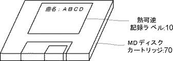
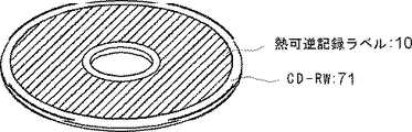
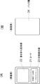
<18> 前記<1>から<17>のいずれかに記載の熱可逆記録媒体における画像を形成する面と反対側の面に、接着剤層及び粘着剤層のいずれかを有することを特徴とする熱可逆記録ラベルである。
<19> 情報記憶部と可逆表示部とを有し、該可逆表示部が前記<1>から<17>のいずれかに記載の熱可逆記録媒体を含むことを特徴とする熱可逆記録部材である。
<20> 情報記憶部と可逆表示部とが一体化された前記<19>に記載の熱可逆記録部材である。
<21> 情報記録部が、磁気記録層、磁気ストライプ、ICメモリ、光メモリ、RF−IDタグカード、ディスク、ディスクカートリッジ及びテープカセットから選択される前記<19>から<20>のいずれかに記載の熱可逆記録部材である。
<22> 印刷可能部分を有する前記<19>から<21>のいずれかに記載の熱可逆記録部材である。
<23> 不可逆な可視情報が、予め感熱層側表面及び裏面の少なくとも一部に形成されている前記<19>から<22>のいずれかに記載の熱可逆記録部材である。
<24> 熱可逆記録媒体を加熱して該熱可逆記録媒体に画像を形成する画像形成手段と、熱可逆記録媒体を加熱して該熱可逆記録媒体に形成された画像を消去する画像消去手段との少なくともいずれかを有してなり、該熱可逆記録媒体が前記<1>から<17>のいずれかに記載の熱可逆記録媒体であることを特徴とする画像処理装置である。
<25> 画像形成手段が、サーマルヘッド及びレーザー照射装置のいずれかである前記<24>に記載の画像処理装置である。
<26> 画像消去手段が、サーマルヘッド、セラミックヒータ、ヒートロール、ホットスタンプ、ヒートブロック及びレーザーから選択されるいずれかである前記<24>から<25>のいずれかに記載の画像処理装置である。
<27> 熱可逆記録媒体を加熱して該熱可逆記録媒体に画像を形成すること、及び、熱可逆記録媒体を加熱して該熱可逆記録媒体に形成された画像を消去することの少なくともいずれかを含み、該熱可逆記録媒体が前記<1>から<17>のいずれかに記載の熱可逆記録媒体であることを特徴とする画像処理方法である。
<28> 画像の形成がサーマルヘッド及びレーザー照射装置のいずれかを用いて行われる前記<27>に記載の画像処理方法である。
<29> 画像の消去がサーマルヘッド、セラミックヒータ、ヒートロール、ホットスタンプ、ヒートブロック及びレーザーから選択されるいずれかを用いて行われる前記<27>から<28>のいずれかに記載の画像処理方法である。
<30> サーマルヘッドを用いて画像を消去しつつ新しい画像を形成する前記<27>から<29>のいずれかに記載の画像処理方法である。
Means for solving the problems are as follows. That is,
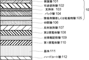
<1> A support, a heat-sensitive layer whose color tone reversibly changes depending on temperature on the support, a protective layer on the heat-sensitive layer, and a surface of the support opposite to the surface on which the heat-sensitive layer is provided. A thermoreversible recording medium comprising a back layer, wherein the back layer contains at least an acicular conductive filler.
<2> The thermoreversible recording medium according to <1>, wherein the protective layer and the back layer include a needle-like conductive filler.
<3> The heat according to any one of <1> to <2>, wherein the long axis of the acicular conductive filler includes a size of 1 μm or more and 10 μm or less, and the short axis includes a size of 0.1 μm or more and 0.5 μm or less. It is a reversible recording medium.
<4> The thermoreversible recording medium according to any one of <1> to <3>, wherein the acicular conductive filler is obtained by surface-treating acicular crystals with a conductive agent.
<5> The thermoreversible recording medium according to <4>, wherein the acicular conductive filler is titanium oxide coated with antimony-doped tin oxide.
<6> The thermoreversible recording medium according to any one of <1> to <5>, wherein the surface resistance value of the exposed outermost layer is 1 × 10 11 Ω / □ or less.
<7> The thermoreversible recording medium according to any one of <1> to <6>, wherein the content of the acicular conductive filler in the layer containing the acicular conductive filler is 10 to 40% by mass. .
<8> The thermoreversible recording medium according to any one of <1> to <7>, wherein a difference in static friction coefficient between the back layer and the protective layer is 0.1 or less.
<9> The thermoreversible recording medium according to any one of <1> to <8>, wherein the static friction coefficient between the back layer and the protective layer is 0.3 or less.
<10> The thermoreversible recording according to any one of <1> to <9>, wherein the back layer and the protective layer contain a binder resin, and the binder resin in the back layer and the binder resin in the protective layer are the same type. It is a medium.
<11> The thermoreversible recording medium according to <10>, wherein the binder resin is at least one of an ultraviolet curable resin and a thermosetting resin.
<12> The thermoreversible recording medium according to <11>, wherein the ultraviolet curable resin is one of a resin that is crosslinked by ultraviolet irradiation and the thermosetting resin is a resin that is crosslinked by an isocyanate compound.
<13> The thermoreversible recording medium according to any one of <1> to <12>, wherein the heat-sensitive layer includes at least an electron donating color-forming compound and an electron-accepting compound.
<14> The thermoreversible recording medium according to <13>, wherein the electron-accepting compound is a phenol compound having an alkyl chain having 8 or more carbon atoms.
<15> The thermoreversible recording medium according to any one of <13> to <14>, wherein the electron donating coloring compound is a leuco dye.
<16> The thermoreversible recording medium according to any one of <1> to <15>, wherein an intermediate layer containing at least an ultraviolet absorber and a curable resin is provided between the thermosensitive layer and the protective layer.
<17> The thermoreversible recording medium according to any one of <1> to <16>, wherein the thermoreversible recording medium is processed into either a card shape or a sheet shape.
<18> The thermoreversible recording medium according to any one of <1> to <17>, wherein an adhesive layer and a pressure-sensitive adhesive layer are provided on a surface opposite to a surface on which an image is formed. This is a thermoreversible recording label.
<19> A thermoreversible recording member comprising an information storage unit and a reversible display unit, wherein the reversible display unit includes the thermoreversible recording medium according to any one of <1> to <17>. is there.
<20> The thermoreversible recording member according to <19>, wherein the information storage unit and the reversible display unit are integrated.
<21> The information recording unit according to any one of <19> to <20>, wherein the information recording unit is selected from a magnetic recording layer, a magnetic stripe, an IC memory, an optical memory, an RF-ID tag card, a disk, a disk cartridge, and a tape cassette. This is a thermoreversible recording member.
<22> The thermoreversible recording member according to any one of <19> to <21>, having a printable part.
<23> The thermoreversible recording member according to any one of <19> to <22>, wherein irreversible visible information is formed in advance on at least a part of the heat-sensitive layer side surface and the back surface.
<24> Image forming means for heating the thermoreversible recording medium to form an image on the thermoreversible recording medium, and image erasing means for heating the thermoreversible recording medium to erase the image formed on the thermoreversible recording medium And the thermoreversible recording medium is the thermoreversible recording medium according to any one of <1> to <17>.
<25> The image processing apparatus according to <24>, wherein the image forming unit is any one of a thermal head and a laser irradiation apparatus.
<26> The image processing apparatus according to any one of <24> to <25>, wherein the image erasing unit is any one selected from a thermal head, a ceramic heater, a heat roll, a hot stamp, a heat block, and a laser. is there.
<27> At least one of heating the thermoreversible recording medium to form an image on the thermoreversible recording medium and heating the thermoreversible recording medium to erase the image formed on the thermoreversible recording medium And the thermoreversible recording medium is the thermoreversible recording medium according to any one of <1> to <17>.
<28> The image processing method according to <27>, wherein the image is formed using either a thermal head or a laser irradiation apparatus.
<29> The image processing according to any one of <27> to <28>, wherein the image is erased using any one selected from a thermal head, a ceramic heater, a heat roll, a hot stamp, a heat block, and a laser. Is the method.
<30> The image processing method according to any one of <27> to <29>, wherein a new image is formed while erasing the image using a thermal head.
本発明の熱可逆記録媒体は、支持体と、該支持体上に温度に依存して色調が可逆的に変化する感熱層と、該感熱層上に保護層と、前記支持体の感熱層を設ける面と反対側にバック層を有し、該バック層が、針状導電性フィラーを少なくとも含む。該本発明の熱可逆記録媒体においては、バック層が、針状導電性フィラーを少なくとも含むことによって、搬送時のローラとの摩擦や熱可逆記録媒体同士の擦れにより発生する静電気を熱可逆記録媒体に溜めることなくリークすることができる。その結果、熱可逆記録媒体同士の貼り付きが抑えられると共に、消去印字時に印字不良の原因となるチリやホコリを吸着しないという効果がある。また、バック層内に針状導電性フィラーを含めることによって各針状導電性フィラーが絡み合い、繰り返し消去印字を行っても熱履歴によるカール発生を抑えることができる。更に、針状導電性フィラーであるため、熱可逆記録媒体の表面にフィラーの端部が現れやすくなり、熱可逆記録媒体表面に凹凸を設けることができ、搬送性が向上する。 The thermoreversible recording medium of the present invention comprises a support, a heat-sensitive layer whose color tone reversibly changes depending on temperature, a protective layer on the heat-sensitive layer, and a heat-sensitive layer of the support. A back layer is provided on the side opposite to the surface to be provided, and the back layer includes at least an acicular conductive filler. In the thermoreversible recording medium of the present invention, the back layer includes at least a needle-like conductive filler, so that static electricity generated by friction with a roller during transportation or friction between thermoreversible recording media is thermally reversible recording medium. It is possible to leak without accumulating. As a result, sticking between thermoreversible recording media can be suppressed, and there is an effect that dust and dust that cause printing defects during erasure printing are not adsorbed. In addition, by including the acicular conductive filler in the back layer, the acicular conductive fillers are entangled and curling due to thermal history can be suppressed even if repeated erasure printing is performed. Furthermore, since it is a needle-like conductive filler, the end of the filler is likely to appear on the surface of the thermoreversible recording medium, and irregularities can be provided on the surface of the thermoreversible recording medium, thereby improving the transportability.
本発明の熱可逆記録ラベルは、本発明の前記熱可逆記録媒体における画像を形成する面と反対側の面に、接着剤層及び粘着剤層のいずれかを有する。該熱可逆記録ラベルでは、前記熱可逆記録媒体部分において、バック層が、針状導電性フィラーを少なくとも含むことによって、帯電防止及びカール発生の防止を図れ、搬送性を著しく向上させることができ、視認性等に優れた画像が形成される。また、前記接着剤層及び粘着剤層のいずれかを有するので、前記感熱層を直接塗布することが困難な磁気ストライプ付塩化ビニル製カード等の厚手の基板、カードサイズよりも大きなシートサイズの容器、ステッカー、大画面、など広範な用途に適用できる。 The thermoreversible recording label of the present invention has either an adhesive layer or a pressure-sensitive adhesive layer on the surface opposite to the image forming surface of the thermoreversible recording medium of the present invention. In the thermoreversible recording label, in the thermoreversible recording medium portion, the back layer includes at least a needle-like conductive filler, thereby preventing charging and curling, and can significantly improve transportability. An image having excellent visibility and the like is formed. Moreover, since it has any one of the adhesive layer and the pressure-sensitive adhesive layer, it is difficult to directly apply the heat-sensitive layer, a thick substrate such as a card made of vinyl chloride with a magnetic stripe, a container having a sheet size larger than the card size , Stickers, large screens, etc.
本発明の熱可逆記録部材は、情報記憶部と可逆表示部とを有し、該可逆表示部が本発明の前記熱可逆記録媒体である。該熱可逆記録部材は、前記可逆表示部において、バック層が、針状導電性フィラーを少なくとも含むことによって、帯電防止及びカール発生の防止を図れ、搬送性を著しく向上させることができ、所望の画像が所望のタイミングで形成され消去される。そして、コントラスト、視認性等に優れた画像が形成される。一方、前記情報記録部では磁気記録層、磁気ストライプ、ICメモリ、光メモリ、RF−IDタグカード、ディスク、ディスクカートリッジ、テープカセット、等の種類に応じた記録方式により、文字情報、画像情報、音楽情報、映像情報等の所望の諸情報が記録され消去される。 The thermoreversible recording member of the present invention has an information storage unit and a reversible display unit, and the reversible display unit is the thermoreversible recording medium of the present invention. In the thermoreversible recording member, in the reversible display portion, the back layer includes at least a needle-like conductive filler, so that antistatic and curling can be prevented, and the transportability can be remarkably improved. An image is formed and erased at a desired timing. And an image excellent in contrast, visibility, etc. is formed. On the other hand, in the information recording section, character information, image information, music, etc. are recorded by a recording method corresponding to the type of magnetic recording layer, magnetic stripe, IC memory, optical memory, RF-ID tag card, disk, disk cartridge, tape cassette, etc. Desired information such as information and video information is recorded and erased.
本発明の画像処理装置は、前記本発明の熱可逆記録媒体を加熱し、画像を形成する画像形成手段及び画像の消去を行う画像消去手段の少なくともいずれかを有する。該画像処理装置においては、前記画像消去手段が、本発明の前記熱可逆記録媒体を加熱して該熱可逆記録媒体に画像を形成する。一方、前記画像形成手段が、本発明の前記熱可逆記録媒体を加熱して該熱可逆記録媒体に形成された画像を消去する。本発明では、前記熱可逆記録媒体として帯電防止及びカール発生の防止を図れ、搬送性が著しく向上した前記本発明の熱可逆記録媒体を用いているので、印字と消去を繰り返してもカールの発生がなく、熱可逆記録媒体が重送や紙詰まりなどの搬送不良となることが防止できる。 The image processing apparatus of the present invention includes at least one of an image forming unit for forming an image by heating the thermoreversible recording medium of the present invention and an image erasing unit for erasing the image. In the image processing apparatus, the image erasing unit heats the thermoreversible recording medium of the present invention to form an image on the thermoreversible recording medium. On the other hand, the image forming means erases the image formed on the thermoreversible recording medium by heating the thermoreversible recording medium of the present invention. In the present invention, as the thermoreversible recording medium, the thermoreversible recording medium of the present invention, which can prevent charging and curl generation and has significantly improved transportability, can be used to generate curl even when printing and erasing are repeated. Therefore, it is possible to prevent the thermoreversible recording medium from being poorly conveyed such as double feeding or paper jam.
本発明の画像処理方法は、前記本発明の熱可逆記録媒体を加熱して画像の形成及び画像の消去の少なくともいずれかを行う。該画像処理方法においては、本発明の前記熱可逆記録媒体を加熱して該熱可逆記録媒体に画像を形成する。一方、本発明の前記熱可逆記録媒体を加熱して該熱可逆記録媒体に形成された画像を消去する。本発明では、前記熱可逆記録媒体として帯電防止及びカール発生の防止を図れ、搬送性が著しく向上した前記本発明の熱可逆記録媒体を用いているので、印字と消去を繰り返し使用してもカールの発生がなく、熱可逆記録媒体が重送や紙詰まりなどの搬送不良が防止できる。 In the image processing method of the present invention, the thermoreversible recording medium of the present invention is heated to perform at least one of image formation and image erasure. In the image processing method, the thermoreversible recording medium of the present invention is heated to form an image on the thermoreversible recording medium. On the other hand, the thermoreversible recording medium of the present invention is heated to erase an image formed on the thermoreversible recording medium. In the present invention, as the thermoreversible recording medium, the thermoreversible recording medium of the present invention, which can prevent charging and curl generation and has significantly improved transportability, is used. Therefore, the thermoreversible recording medium can be prevented from being poorly conveyed such as double feeding or paper jam.
本発明によると、従来における諸問題を解決でき、熱エネルギーを制御することにより発色画像の形成と消去が可能な熱可逆記録媒体において、プリンター搬送性に優れ、繰り返し使用しても媒体同士の貼り付きが無く、しかも繰り返し使用によるカールの発生がなく、使用中にゴミなどの付着がしにくく、使用環境が低温低湿環境から高温高湿環境で使用しても搬送性に優れた熱可逆記録媒体等を提供することができる。 According to the present invention, in a thermoreversible recording medium that can solve various problems in the past and can form and erase a color image by controlling thermal energy, the printer is excellent in transportability and can be stuck between repeated use. A thermoreversible recording medium that has no sticking, does not cause curling due to repeated use, is less likely to adhere dust during use, and has excellent transportability even when used in a low-temperature, low-humidity environment to a high-temperature, high-humidity environment Etc. can be provided.
(熱可逆記録媒体)
本発明の熱可逆記録媒体は、支持体と、バック層と、保護層と、感熱層とを少なくとも有してなり、更に必要に応じてその他の層を有してなる。
(Thermal reversible recording medium)
The thermoreversible recording medium of the present invention includes at least a support, a back layer, a protective layer, and a heat-sensitive layer, and further includes other layers as necessary.
<支持体>
前記支持体としては、その形状、構造、大きさ等については、特に制限はなく、目的に応じて適宜選択することができ、前記形状としては、例えば平板状などが挙げられ、前記構造としては、単層構造であってもいし、積層構造であってもよく、前記大きさとしては、前記熱可逆記録媒体の大きさ等に応じて適宜選択することができる。
<Support>
The support is not particularly limited in its shape, structure, size, etc., and can be appropriately selected according to the purpose. Examples of the shape include a flat plate shape. It may be a single layer structure or a laminated structure, and the size can be appropriately selected according to the size of the thermoreversible recording medium.
前記支持体の材料としては、例えば、無機材料、有機材料、などが挙げられる。前記無機材料としては、例えば、ガラス、石英、シリコン、酸化シリコン、酸化アルミニウム、SiO2、金属等が挙げられる。前記有機材料としては、例えば、紙、三酢酸セルロース等のセルロース誘導体、合成紙、ポリエチレンテレフタレート、ポリカーボネート、ポリスチレン、ポリメチルメタクリレート等が挙げられる。これらは、1種単独で使用してもよいし、2種以上を併用してもよい。 Examples of the material for the support include inorganic materials and organic materials. Examples of the inorganic material include glass, quartz, silicon, silicon oxide, aluminum oxide, SiO 2 and metal. Examples of the organic material include paper, cellulose derivatives such as cellulose triacetate, synthetic paper, polyethylene terephthalate, polycarbonate, polystyrene, and polymethyl methacrylate. These may be used individually by 1 type and may use 2 or more types together.
前記支持体には、塗布層の接着性を向上させる目的で、コロナ放電処理、酸化反応処理(クロム酸等)、エッチング処理、易接着処理、帯電防止処理、等により表面改質することが好ましい。また、前記支持体には、酸化チタン等の白色顔料などを添加して白色にすることが好ましい。
前記支持体の厚みとしては、特に制限はなく、目的に応じて適宜選択することができ、50〜2,000μmが好ましく、100〜1,000μmがより好ましい。
The support is preferably surface-modified by corona discharge treatment, oxidation reaction treatment (chromic acid, etc.), etching treatment, easy adhesion treatment, antistatic treatment, etc. for the purpose of improving the adhesion of the coating layer. . Moreover, it is preferable to add a white pigment such as titanium oxide to the support to make it white.
There is no restriction | limiting in particular as thickness of the said support body, According to the objective, it can select suitably, 50-2,000 micrometers is preferable and 100-1,000 micrometers is more preferable.
<バック層>
前記バック層は、前記支持体の感熱層を設ける面と反対側の面(裏面)に形成されていれば特に制限はなく、目的に応じて適宜選択することができ、1層以上の複数層に形成してもよく、特に、露出した最表面(最裏面)であることが好ましい。
前記バック層には、針状導電性フィラーを少なくとも含有し、バインダー樹脂、更に必要に応じて、他のフィラー、滑剤、着色顔料等のその他の成分を含有してなる。
<Back layer>
The back layer is not particularly limited as long as it is formed on the surface (back surface) opposite to the surface on which the heat-sensitive layer of the support is provided, and can be appropriately selected according to the purpose. In particular, the exposed outermost surface (outermost surface) is preferable.
The back layer contains at least an acicular conductive filler, and contains a binder resin and, if necessary, other components such as other fillers, lubricants, and color pigments.
本発明においては、前記バック層が針状導電性フィラーを含むことにより、搬送時のローラとの摩擦や熱可逆記録媒体同士の擦れにより発生する静電気を熱可逆記録媒体に溜めることなくリークすることができる。これにより、熱可逆記録媒体の貼り付きが抑えられると共に、消去印字時に印字不良の原因となるチリやホコリを吸着しないという効果がある。また、バック層内に針状導電性フィラーを含めることによって各針状導電性フィラーが絡み合うために繰り返し消去印字を行っても熱履歴によるカール発生を抑えることができる。しかも、針状導電性フィラーであるため、熱可逆記録媒体表面にフィラーの端部が現れやすくなり、熱可逆記録媒体表面に凹凸を設けることができ、搬送性が向上する。 In the present invention, the back layer contains a needle-like conductive filler, so that static electricity generated due to friction with a roller during transportation or friction between thermoreversible recording media leaks without accumulating in the thermoreversible recording medium. Can do. As a result, sticking of the thermoreversible recording medium is suppressed, and there is an effect that dust and dust that cause printing defects during erasure printing are not adsorbed. Further, by including the acicular conductive filler in the back layer, the acicular conductive fillers are entangled with each other, so that the occurrence of curling due to the thermal history can be suppressed even if repeated erasure printing is performed. Moreover, since it is a needle-like conductive filler, the end of the filler is likely to appear on the surface of the thermoreversible recording medium, and irregularities can be provided on the surface of the thermoreversible recording medium, thereby improving the transportability.
−針状導電性フィラー−
前記針状導電性フィラーとしては、特に制限はなく、目的に応じて適宜選択することができ、例えば、針状結晶を導電剤で表面処理したもの、などが好適である。
-Needle-shaped conductive filler-
There is no restriction | limiting in particular as said acicular conductive filler, According to the objective, it can select suitably, For example, what surface-treated the acicular crystal | crystallization with the electrically conductive agent etc. are suitable.
前記針状結晶としては、例えば、酸化チタン、チタン酸カリウム、ホウ酸アルミニウム、炭化珪素、窒化珪素、等が挙げられる。これらの中でも、結晶成長のコントロールし易さ、安定したサイズの結晶を得ることが可能な点から、酸化チタンが特に好ましい。また、前記酸化チタンは、塗工液を作成する際の分散時に破壊されない強度を持ち、塗膜にした時の表面を粗し、表面強度と硬さを維持できる点からも好適である。 Examples of the acicular crystals include titanium oxide, potassium titanate, aluminum borate, silicon carbide, and silicon nitride. Among these, titanium oxide is particularly preferable from the viewpoint of easy control of crystal growth and the ability to obtain crystals of a stable size. The titanium oxide is also preferable in that it has a strength that is not destroyed during dispersion when creating a coating liquid, can roughen the surface of the coating film, and maintain the surface strength and hardness.
前記導電剤としては、特に制限はなく、目的に応じて適宜選択することができ、例えば、アンチモンドープ酸化スズ、スズドープ酸化インジウム、アルミドープ酸化亜鉛、フッ素ドープ酸化スズ、等が挙げられる。これらの中でも、表面電気抵抗率の安定性、金属電気伝導性、安定性、コストの点から、アンチモンドープ酸化スズが特に好ましい。該アンチモンドープ酸化スズで針状結晶を被覆することによって、水の介在が無くても記録媒体に発生した静電気をリークすることができる機能を失うことがなく、バック層は湿度依存性が無い物性となる。 There is no restriction | limiting in particular as said electrically conductive agent, According to the objective, it can select suitably, For example, antimony dope tin oxide, tin dope indium oxide, aluminum dope zinc oxide, fluorine dope tin oxide etc. are mentioned. Among these, antimony-doped tin oxide is particularly preferable from the viewpoints of surface electrical resistivity stability, metal electrical conductivity, stability, and cost. By covering the acicular crystals with the antimony-doped tin oxide, the back layer has no humidity dependency without losing the function of leaking static electricity generated in the recording medium without the presence of water. It becomes.
前記針状導電性フィラーとしては、具体的には、アンチモンドープ酸化スズで表面が被覆されている酸化チタンが特に好ましい。前記針状導電性フィラーが酸化チタンからなるためフィラーの強度を高めることができることにより、繰り返し消去印字時のヘッドによる熱と圧力の影響、搬送ローラとの摩擦、接触、熱可逆記録媒体同士が擦れ合う時の摩擦の影響を受けずに表面に凹凸を設けることができる。 Specifically, the needle-like conductive filler is particularly preferably titanium oxide whose surface is coated with antimony-doped tin oxide. Since the needle-like conductive filler is made of titanium oxide, the strength of the filler can be increased, so that the influence of heat and pressure by the head during repeated erasure printing, friction with the conveying roller, contact, and thermoreversible recording media rub against each other. Irregularities can be provided on the surface without being affected by friction at the time.
前記針状導電性フィラーは、フィラー同士が有効に重なり合って、静電気のリーク効果を向上させることができる観点から、長軸は1μm以上10μm以下であり、かつ短軸は0.1μm以上0.5μm以下が好ましく、長軸は2μm以上8μm以下であり、かつ短軸は0.15μm以上0.4μm以下がより好ましく、長軸は3μm以上7μm以下であり、かつ短軸は0.2μm以上0.35μm以下が特に好ましい。
前記長軸が1μm未満であると、フィラーの重なりが不十分となり静電気のリーク効果が低下してしまうことがあり、また、塗工膜の表面にフィラーが現れなくなり静電気の逃げ場がなくなると共に、表面が平滑となり、熱可逆記録媒体の密着による搬送不良が発生することがある。一方、長軸が10μmを超えると、熱可逆記録媒体の表面に大きく浮き出し、搬送の妨げとなることがある。
また、前記短軸が0.1μm未満であると、フィラーの強度が不十分となり、特に表面に現れている部分が繰り返し消去印字を行っていく過程で摩耗が発生し、初期状態の効果を維持することが難しくなることがある。一方、0.5μmを超えると、針状導電性フィラーが太くなりすぎるため、表面に大きな凹凸が現れて搬送時の妨げとなることがある。
The needle-shaped conductive filler has a major axis of 1 μm or more and 10 μm or less and a minor axis of 0.1 μm or more and 0.5 μm from the viewpoint that fillers can be effectively overlapped to improve the static electricity leakage effect. The major axis is 2 μm or more and 8 μm or less, the minor axis is more preferably 0.15 μm or more and 0.4 μm or less, the major axis is 3 μm or more and 7 μm or less, and the minor axis is 0.2 μm or more and 0.2 μm or less. 35 μm or less is particularly preferable.
If the long axis is less than 1 μm, the overlap of fillers may be insufficient and the static electricity leakage effect may be reduced, the filler may not appear on the surface of the coating film, and there will be no static electricity escape. May become smooth and poor conveyance may occur due to adhesion of the thermoreversible recording medium. On the other hand, if the major axis exceeds 10 μm, it may be greatly raised on the surface of the thermoreversible recording medium, which may hinder conveyance.
Further, if the minor axis is less than 0.1 μm, the strength of the filler becomes insufficient, and wear occurs particularly in the process of repeatedly erasing and printing the portion appearing on the surface, maintaining the effect of the initial state. Can be difficult to do. On the other hand, when the thickness exceeds 0.5 μm, the needle-like conductive filler becomes too thick, so that large irregularities appear on the surface, which may hinder transportation.
前記針状導電性フィラーの前記バック層中における含有量は、10〜40質量%が好ましく、15〜35質量%がより好ましく、17〜25質量%が更に好ましい。
前記含有量が10質量%未満であると、針状導電性フィラーの重なり合いが不十分となり、急激に表面抵抗値が高くなり、結果として搬送不良が発生することがあり、40質量%を超えると、表面に多くのフィラーが現れ、熱可逆記録媒体表面に大きな凹凸が現れ、熱可逆記録媒体の搬送性を低下させてしまうと共に、搬送用ローラやサーマルヘッドやその他の部材を摩耗させてしまうことがある。
10-40 mass% is preferable, as for content in the said back layer of the said acicular conductive filler, 15-35 mass% is more preferable, and 17-25 mass% is still more preferable.
When the content is less than 10% by mass, the overlapping of the needle-like conductive fillers becomes insufficient, the surface resistance value rapidly increases, and as a result, conveyance failure may occur, and when the content exceeds 40% by mass. Many fillers appear on the surface, large irregularities appear on the surface of the thermoreversible recording medium, which deteriorates the transportability of the thermoreversible recording medium and wears the transport roller, thermal head, and other members. There is.
−バインダー樹脂−
前記バインダー樹脂としては、特に制限はなく、目的に応じて適宜選択することができ、例えば、熱硬化性樹脂、紫外線(UV)硬化性樹脂、電子線硬化性樹脂、等が挙げられ、これらの中でも、紫外線(UV)硬化性樹脂、熱硬化性樹脂が特に好ましい。
前記UV硬化性樹脂は、硬化後非常に硬い膜を形成することができ、繰り返し耐久性に優れたバック層が得られる。また、前記熱硬化性樹脂は、前記UV硬化性樹脂にはやや劣るが表面を硬くすることができ、繰り返し耐久性に優れる。
-Binder resin-
There is no restriction | limiting in particular as said binder resin, According to the objective, it can select suitably, For example, a thermosetting resin, an ultraviolet-ray (UV) curable resin, an electron beam curable resin, etc. are mentioned, These Among these, ultraviolet (UV) curable resins and thermosetting resins are particularly preferable.
The UV curable resin can form a very hard film after curing, and a back layer excellent in repeated durability can be obtained. The thermosetting resin is slightly inferior to the UV curable resin, but can harden the surface and is excellent in repeated durability.
前記UV硬化性樹脂としては、特に制限はなく、公知のものの中から目的に応じて適宜選択することができ、例えば、ウレタンアクリレート系、エポキシアクリレート系、ポリエステルアクリレート系、ポリエーテルアクリレート系、ビニル系、不飽和ポリエステル系のオリゴマーや各種単官能、多官能のアクリレート、メタクリレート、ビニルエステル、エチレン誘導体、アリル化合物等のモノマーが挙げられる。これらの中でも、4官能以上の多官能性のモノマー又はオリゴマーが特に好ましい。これらのモノマー又はオリゴマーを2種類以上混合することで樹脂膜の硬さ、収縮度、柔軟性、塗膜強度等を適宜調節することができる。 There is no restriction | limiting in particular as said UV curable resin, According to the objective, it can select suitably according to the objective, for example, urethane acrylate type, epoxy acrylate type, polyester acrylate type, polyether acrylate type, vinyl type And monomers such as unsaturated polyester oligomers and various monofunctional and polyfunctional acrylates, methacrylates, vinyl esters, ethylene derivatives, and allyl compounds. Among these, tetrafunctional or higher polyfunctional monomers or oligomers are particularly preferable. By mixing two or more of these monomers or oligomers, the hardness, shrinkage, flexibility, coating strength, etc. of the resin film can be appropriately adjusted.
前記多官能性モノマー又はオリゴマーとしては、例えば、トリメチロールプロパントリアクリレート、ペンタエリスリトールトリアクリレート、グリセリンPO付加トリアクリレート、トリスアクリロイルオキシエチルフォスフェート、ペンタエリスリトールテトラアクリレート、トリメチロールプロパンのプロピレンオキサイド3モル付加物のトリアクリレート、グリセリルプロポキシトリアクリレート、ジペンタエリスリトール・ポリアクリレート、ジペンタエリスリトールのカプロラクトン付加物のポリアクリレート、プロピオン酸・ジペンタエリスリトールトリアクリレート、ヒドロキシピバルアルデヒド変性ジメチロールプロピントリアクリレート、プロピオン酸・ジペンタエリスリトールのテトラアクリレート、ジトリメチロールプロパンテトラアクリレート、プロピオン酸ジペンタエリスリトールのペンタアクリレート、トリメチロールプロパントリアクリレート付加ウレタンプレポリマー、ジペンタエリスリトールヘキサアクリレート(DPHA)、DPHAのε−カプロラクトン付加物、等が挙げられる。 Examples of the polyfunctional monomer or oligomer include trimethylolpropane triacrylate, pentaerythritol triacrylate, glycerin PO-added triacrylate, trisacryloyloxyethyl phosphate, pentaerythritol tetraacrylate, trimethylolpropane propylene oxide 3 mol addition Triacrylate, glyceryl propoxytriacrylate, dipentaerythritol polyacrylate, polyacrylate of dipentaerythritol caprolactone adduct, propionic acid / dipentaerythritol triacrylate, hydroxypivalaldehyde-modified dimethylolpropyne triacrylate, propion Acid / dipentaerythritol tetraacrylate, ditrimethylo Propane tetraacrylate, pentaacrylate of dipentaerythritol propionate, trimethylolpropane triacrylate added urethane prepolymer, dipentaerythritol hexaacrylate (DPHA), .epsilon.-caprolactone adduct of DPHA, and the like.
また、前記モノマー又はオリゴマーを紫外線を用いて硬化させるためには、光重合開始剤、光重合促進剤を用いる必要がある。
前記光重合開始剤としては、ラジカル反応型とイオン反応型に大別でき、更に、ラジカル反応型は光開裂型と水素引抜き型とに分けられる。
前記光重合開始剤としては、例えば、イソブチルベンゾインエーテル、イソプロピルベンゾインエーテル、ベンゾインエチルエーテルベンゾインメチルエーテル、1−フェニル−1,2−プロパンジオン−2−(o−エトキシシカルボニル)オキシム、2,2−ジメトキシ−2−フェニルアセトフェノンベンジル、ヒドロキシシクロヘキシルフェニルケトン、ジエトキシアセトフェノン、2−ヒドロキシ−2−メチル−1−フェニルプロパン−1−オン、ベンゾフェノン、クロロチオキサントン、2−クロロチオキサントン、イソプロピルチオキサントン、2−メチルチオキサントン、塩素置換ベンゾフェノン等が挙げられ、単独で又は2種以上混合して使用されるが、これらに限定されるものではない。
In order to cure the monomer or oligomer using ultraviolet rays, it is necessary to use a photopolymerization initiator and a photopolymerization accelerator.
The photopolymerization initiator can be roughly classified into a radical reaction type and an ion reaction type, and the radical reaction type is further classified into a photocleavage type and a hydrogen abstraction type.
Examples of the photopolymerization initiator include isobutyl benzoin ether, isopropyl benzoin ether, benzoin ethyl ether benzoin methyl ether, 1-phenyl-1,2-propanedione-2- (o-ethoxycycarbonyl) oxime, 2,2 -Dimethoxy-2-phenylacetophenone benzyl, hydroxycyclohexyl phenyl ketone, diethoxyacetophenone, 2-hydroxy-2-methyl-1-phenylpropan-1-one, benzophenone, chlorothioxanthone, 2-chlorothioxanthone, isopropylthioxanthone, 2- Examples thereof include methylthioxanthone and chlorine-substituted benzophenone, and are used alone or as a mixture of two or more thereof, but are not limited thereto.
前記光重合促進剤としては、ベンゾフェノン系やチオキサントン系などの水素引抜きタイプの光重合開始剤に対し、硬化速度を向上させる効果を有するものが好ましく、例えば、芳香族系の第3級アミンや脂肪族アミン系、などが挙げられる。具体的には、p−ジメチルアミノ安息香酸イソアミルエステル、p−ジメチルアミノ安息香酸エチルエステルなどが挙げられる。これら光重合促進剤は単独で又は2種以上混合して使用される。
前記光重合開始剤又は光重合促進剤の添加量は、前記バック層の樹脂成分の全質量に対し0.1〜20質量%が好ましく、1〜10質量%がより好ましい。
As the photopolymerization accelerator, those having an effect of improving the curing rate with respect to hydrogen abstraction type photopolymerization initiators such as benzophenone series and thioxanthone series are preferable. For example, aromatic tertiary amines and Group amine-based, and the like. Specific examples include p-dimethylaminobenzoic acid isoamyl ester and p-dimethylaminobenzoic acid ethyl ester. These photopolymerization accelerators are used alone or in combination of two or more.
0.1-20 mass% is preferable with respect to the total mass of the resin component of the said back layer, and, as for the addition amount of the said photoinitiator or a photoinitiator, 1-10 mass% is more preferable.
前記熱硬化性樹脂としては、特に制限はなく、公知のものの中から目的に応じて適宜選択することができ、例えば、水酸基やカルボキシル基等の架橋剤と反応する基を持つ樹脂、又は水酸基やカルボキシル基等を持つモノマーとそれ以外のモノマーを共重合した樹脂などが挙げられる。このような熱硬化性樹脂としては、例えば、フェノキシ樹脂、ポリビニルブチラール樹脂、セルロースアセテートプロピオネート樹脂、セルロースアセテートブチレート樹脂、アクリルポリオール樹脂、ポリエステルポリオール樹脂、ポリウレタンポリオール樹脂、等が挙げられる。これらの中でも、アクリルポリオール樹脂、ポリエステルポリオール樹脂、ポリウレタンポリオール樹脂が特に好ましい。 The thermosetting resin is not particularly limited and can be appropriately selected from known ones according to the purpose. For example, a resin having a group that reacts with a crosslinking agent such as a hydroxyl group or a carboxyl group, or a hydroxyl group or Examples thereof include a resin obtained by copolymerizing a monomer having a carboxyl group or the like and another monomer. Examples of such thermosetting resins include phenoxy resins, polyvinyl butyral resins, cellulose acetate propionate resins, cellulose acetate butyrate resins, acrylic polyol resins, polyester polyol resins, polyurethane polyol resins, and the like. Among these, acrylic polyol resin, polyester polyol resin, and polyurethane polyol resin are particularly preferable.
前記アクリルポリオール樹脂は、(メタ)アクリル酸エステル単量体と、カルボン酸基を有する不飽和単量体、水酸基を有する不飽和単量体、及びその他のエチレン性不飽和単量体とを用い、公知の溶液重合法、懸濁重合法、乳化重合法等に従って合成することができる。
前記水酸基を有する不飽和単量体としては、例えば、ヒドロキシエチルアクリレート(HEA)、ヒドロキシプロピルアクリレート(HPA)、2−ヒドロキシエチルメタクリレート(HEMA)、2−ヒドロキシプロピルメタクリレート(HPMA)、2−ヒドロキシブチルモノアクリレート(2−HBA)、1,4−ヒドロキシブチルモノアクリレート(1−HBA)などが用いられるが、第1級水酸基をもつモノマーを使用した方が塗膜のワレ抵抗性や耐久性が良いことから、2−ヒドロキシエチルメタクリレートが好ましく用いられる。
前記アクリルポリオール樹脂は、画像の印字・消去の繰返し耐久性を向上させる観点からは、架橋剤を用いて架橋させておくことが好ましい。該架橋は、例えば、熱、紫外線、電子線などにより行うことができる。これらの中でも、低コストで容易に行うことができ、硬化のための長期保存が不要な点で、熱や紫外線による架橋が好ましい。
The acrylic polyol resin uses a (meth) acrylic acid ester monomer, an unsaturated monomer having a carboxylic acid group, an unsaturated monomer having a hydroxyl group, and other ethylenically unsaturated monomers. It can be synthesized according to a known solution polymerization method, suspension polymerization method, emulsion polymerization method and the like.
Examples of the unsaturated monomer having a hydroxyl group include hydroxyethyl acrylate (HEA), hydroxypropyl acrylate (HPA), 2-hydroxyethyl methacrylate (HEMA), 2-hydroxypropyl methacrylate (HPMA), and 2-hydroxybutyl. Monoacrylate (2-HBA), 1,4-hydroxybutyl monoacrylate (1-HBA) and the like are used, but the use of a monomer having a primary hydroxyl group has better crack resistance and durability of the coating film. Therefore, 2-hydroxyethyl methacrylate is preferably used.
The acrylic polyol resin is preferably cross-linked using a cross-linking agent from the viewpoint of improving the repeated durability of image printing / erasing. The crosslinking can be performed by, for example, heat, ultraviolet light, electron beam or the like. Among these, crosslinking by heat or ultraviolet rays is preferable because it can be easily carried out at low cost and does not require long-term storage for curing.
前記架橋剤としては、特に制限はなく、目的に応じて適宜選択することができ、例えば、イソシアネート類、アミノ樹脂、フェノール樹脂、アミン類、エポキシ化合物、等が挙げられる。これらの中でも、イソシアネート類が好ましく、特に好ましくはイソシアネート基を複数持つポリイソシアネート化合物である。
前記イソシアネート類としては、例えば、ヘキサメチレンジイソシアネート(HDI)、トリレンジイソシアネート(TDI)、キシリレンジイソシアネート(XDI)、又はこれらのトリメチロールプロパン等によるアダクトタイプ、ビュレットタイプ、イソシアヌレートタイプ、又はブロック化イソシアネート類等が挙げられる。
There is no restriction | limiting in particular as said crosslinking agent, According to the objective, it can select suitably, For example, isocyanate, amino resin, a phenol resin, amines, an epoxy compound, etc. are mentioned. Among these, isocyanates are preferable, and polyisocyanate compounds having a plurality of isocyanate groups are particularly preferable.
Examples of the isocyanates include hexamethylene diisocyanate (HDI), tolylene diisocyanate (TDI), xylylene diisocyanate (XDI), or adduct type, burette type, isocyanurate type, or blocking with trimethylolpropane. Isocyanates and the like.
前記架橋剤のバインダー樹脂に対する添加量は、バインダー樹脂中に含まれる活性基の数に対する架橋剤の官能基の比は0.01〜2が好ましい。これ以下では熱強度が不足してしまい、また、これ以上添加すると発色・消色特性に悪影響を及ぼす。
更に、架橋促進剤としてこの種の反応に用いられる触媒を用いてもよい。該架橋促進剤としては、例えば、1,4−ジアザビシクロ〔2,2,2〕オクタン等の3級アミン類、有機スズ化合物等の金属化合物、などが挙げられる。
前記熱架橋した場合の熱硬化性樹脂のゲル分率は、30%以上が好ましく、50%以上がより好ましく、70%以上が更に好ましい。前記ゲル分率が30%未満であると、架橋状態が十分でなく耐久性に劣ることがある。
As for the addition amount with respect to the binder resin of the said crosslinking agent, the ratio of the functional group of a crosslinking agent with respect to the number of the active groups contained in binder resin has 0.01-2. Below this temperature, the heat intensity is insufficient, and when added more than this, the coloring / decoloring properties are adversely affected.
Furthermore, you may use the catalyst used for this kind of reaction as a crosslinking accelerator. Examples of the crosslinking accelerator include tertiary amines such as 1,4-diazabicyclo [2,2,2] octane, metal compounds such as organotin compounds, and the like.
The gel fraction of the thermosetting resin when thermally crosslinked is preferably 30% or more, more preferably 50% or more, and still more preferably 70% or more. When the gel fraction is less than 30%, the crosslinked state is not sufficient and the durability may be inferior.
前記熱硬化性樹脂の水酸基価は70KOHmg/g以上が好ましく、90KOHmg/g以上がより好ましい。前記水酸基価が70KOHmg/g以上であると、耐久性、塗膜表面硬度、ワレ抵抗性が向上する。 The hydroxyl value of the thermosetting resin is preferably 70 KOHmg / g or more, more preferably 90 KOHmg / g or more. When the hydroxyl value is 70 KOHmg / g or more, durability, coating surface hardness, and crack resistance are improved.
前記バック層には、前記針状導電性フィラー及び前記バインダー樹脂の他に、更に必要に応じて、他のフィラー、滑剤、着色顔料等のその他の成分を添加することができる。 In addition to the acicular conductive filler and the binder resin, other components such as other fillers, lubricants, and color pigments can be added to the back layer as necessary.
前記他のフィラーとしては、針状導電性フィラー以外であれば特に制限はなく、球状等の形状であってもよく、例えば、無機フィラー、有機フィラーなどが挙げられる。
前記無機フィラーとしては、例えば、炭酸塩、ケイ酸塩、金属酸化物、硫酸化合物、等が挙げられる。前記有機フィラーとしては、例えば、シリコーン樹脂、セルロース樹脂、エポキシ樹脂、ナイロン樹脂、フェノール樹脂、ポリウレタン樹脂、ユリア樹脂、メラミン樹脂、ポリエステル樹脂、ポリカーボネート樹脂、スチレン系樹脂、アクリル系樹脂、ポリエチレン樹脂、ホルムアルデヒド系樹脂、ポリメチルメタクリレート樹脂、等が挙げられる。
前記他のフィラーの前記バック層における含有量は、1〜20質量%が好ましい。
前記含有量が、1質量%未満であると、フィラー添加による表面性に効果がなくなることがあり、20質量%を超えると、針状導電性フィラーの帯電防止効果を弱めてしまうことがある。
The other filler is not particularly limited as long as it is other than the acicular conductive filler, and may be spherical or the like, and examples thereof include an inorganic filler and an organic filler.
Examples of the inorganic filler include carbonates, silicates, metal oxides, sulfate compounds, and the like. Examples of the organic filler include silicone resin, cellulose resin, epoxy resin, nylon resin, phenol resin, polyurethane resin, urea resin, melamine resin, polyester resin, polycarbonate resin, styrene resin, acrylic resin, polyethylene resin, formaldehyde Resin, polymethyl methacrylate resin, and the like.
The content of the other filler in the back layer is preferably 1 to 20% by mass.
When the content is less than 1% by mass, the effect on the surface properties due to the addition of the filler may be lost, and when it exceeds 20% by mass, the antistatic effect of the acicular conductive filler may be weakened.
前記滑剤としては、例えば、合成ワックス類、植物性ワックス類、動物性ワックス類、高級アルコール類、高級脂肪酸類、高級脂肪酸エステル類、アミド類、などが挙げられる。また、バック層を着色して表裏の区別ができるように着色してもよい。該着色させるには染料や顔料を用いることが好ましく、熱により繰り返し履歴がかかるため顔料を用いることが特に好ましい。 Examples of the lubricant include synthetic waxes, vegetable waxes, animal waxes, higher alcohols, higher fatty acids, higher fatty acid esters, amides, and the like. Moreover, you may color so that a back layer can be colored and the front and back can be distinguished. For coloring, it is preferable to use a dye or a pigment, and it is particularly preferable to use a pigment because it takes a repeated history due to heat.
前記バック層の形成方法としては、特に制限はなく、目的に応じて適宜選択することができ、前記針状導電性フィラー、前記バインダー樹脂、前記その他の添加物を、溶媒と一緒に混合してなる混合物を均一に混合分散させて調製した塗液を用いる。 The method for forming the back layer is not particularly limited and can be appropriately selected according to the purpose. The acicular conductive filler, the binder resin, and the other additives are mixed together with a solvent. A coating liquid prepared by uniformly mixing and dispersing the resulting mixture is used.
前記溶媒としては、特に制限はなく、目的に応じて適宜選択することができ、例えば、水、アルコール、ケトン、アミド、エーテル類、グリコール類、グリコールエーテル類、グリコールエステルアセテート類、エステル類、芳香族炭化水素類、脂肪族炭化水素類、ハロゲン化炭化水素類、スルホキシド類、ピロリドン類、等が挙げられる。これらの中でも、水、メタノール、エタノール、イソプロパノール,n−ブタノール、アセトン、メチルエチルケトン、メチルイソブチルケトン、シクロヘキサノン、N,N−ジメチルホルムアミド、N,N−ジメチルアセトアミド、テトラヒドロフラン、1,4−ジオキサン、3,4−ジヒドロ−2H−ピラン、2−メトキシエタノール、2−エトキシエタノール、2−ブトキシエタノール、酢酸メチル、酢酸エチル、酢酸ブチル、トルエン、キシレン、ヘキサン、ヘプタン、シクロヘキサン、ジメチルスルホキシド、等が好適である。更に、水、イソプロパノール、n−ブタノール、メチルエチルケトン、メチルイソブチルケトン、シクロヘキサノン、テトラヒドロフラン、酢酸エチル、酢酸ブチル、トルエン、キシレン、等が特に好適である。
なお、前記塗液の調製は、例えば、ペイントシェーカー、ボールミル、アトライター、三本ロールミル、ケディーミル、サンドミル、ダイノミル、コロイドミル、等の公知の塗液分散装置を用いて行うことができる。
The solvent is not particularly limited and may be appropriately selected depending on the intended purpose. For example, water, alcohol, ketone, amide, ethers, glycols, glycol ethers, glycol ester acetates, esters, aromatics Aromatic hydrocarbons, aliphatic hydrocarbons, halogenated hydrocarbons, sulfoxides, pyrrolidones, and the like. Among these, water, methanol, ethanol, isopropanol, n-butanol, acetone, methyl ethyl ketone, methyl isobutyl ketone, cyclohexanone, N, N-dimethylformamide, N, N-dimethylacetamide, tetrahydrofuran, 1,4-dioxane, 3, 4-dihydro-2H-pyran, 2-methoxyethanol, 2-ethoxyethanol, 2-butoxyethanol, methyl acetate, ethyl acetate, butyl acetate, toluene, xylene, hexane, heptane, cyclohexane, dimethyl sulfoxide, etc. are preferred. . Furthermore, water, isopropanol, n-butanol, methyl ethyl ketone, methyl isobutyl ketone, cyclohexanone, tetrahydrofuran, ethyl acetate, butyl acetate, toluene, xylene and the like are particularly suitable.
The coating liquid can be prepared using a known coating liquid dispersing apparatus such as a paint shaker, a ball mill, an attritor, a three roll mill, a keddy mill, a sand mill, a dyno mill, or a colloid mill.
前記バック層の塗工方法としては、特に制限はなく、目的に応じて適宜選択することができ、ロール状で連続して、又はシート状に裁断した支持体を搬送し、該支持体上に、例えば、ブレード塗工、ワイヤーバー塗工、スプレー塗工、エアナイフ塗工、ビード塗工、カーテン塗工、グラビア塗工、キス塗工、リバースロール塗工、ディップ塗工、ダイ塗工等公知の方法で塗布する。そして、塗布したシートは、引き続き、送風乾燥機の中に搬送され、30〜150℃にて10秒〜10分間乾燥される。 The coating method for the back layer is not particularly limited and may be appropriately selected depending on the purpose. A support that is continuously cut in a roll shape or cut into a sheet shape is transported on the support. For example, blade coating, wire bar coating, spray coating, air knife coating, bead coating, curtain coating, gravure coating, kiss coating, reverse roll coating, dip coating, die coating, etc. Apply by the method. And the apply | coated sheet | seat is continuously conveyed in a ventilation dryer, and is dried for 10 seconds-10 minutes at 30-150 degreeC.
この場合特に、無欠陥塗工を行うためには、塗布液は事前や送液中に通常の濾紙の他、ステンレスメッシュ、ナイロンメッシュ等の網、又はコットンフィルター、ファイバーカーボンフィルター等の天然又は合成繊維系フィルター、メンブランフィルター等の膜濾過を通したり、超音波を1分〜200時間、好ましくは10分〜80時間掛けることによって異物を除いたり、泡の混入、分散物の凝集を避けることができる。 In this case, in particular, in order to perform defect-free coating, the coating solution is natural or synthetic such as a conventional filter paper, a mesh such as stainless mesh, nylon mesh, or a cotton filter, a fiber carbon filter, etc. in advance or during feeding. To avoid foreign matters, avoid mixing of bubbles, and agglomeration of dispersions by passing through membrane filtration such as fiber filters and membrane filters, or applying ultrasonic waves for 1 minute to 200 hours, preferably 10 minutes to 80 hours. it can.
また、前記塗布は、クラス10,000以下のクリーンルーム内で行うことが好ましい。
前記乾燥には、フィルター及び除湿装置を通した空気又は窒素等の不活性ガスを熱し、これを表面から、裏面から、又は双方から吹き付けるのが好ましい。これらの中でも、コットンフィルターやメンブランフィルターによる濾過や超音波照射が好ましい。上記のような装置を適宜選択して使用することにより塗布層の均一性が向上する。
The application is preferably performed in a clean room of class 10,000 or less.
For the drying, it is preferable to heat an inert gas such as air or nitrogen that has passed through a filter and a dehumidifier, and spray this from the front surface, the back surface, or both. Among these, filtration by a cotton filter or a membrane filter or ultrasonic irradiation is preferable. The uniformity of the coating layer is improved by appropriately selecting and using the apparatus as described above.
前記バック層が熱硬化の場合には、塗布乾燥した後、更に必要に応じてキュアを行うことが好ましい。該キュアによって、熱架橋の場合は架橋を促進することができる。それ以外の場合も残留溶剤を低減させて品質安定化を図れる。恒温槽等を用いて比較的高温で短時間でもよく、また、比較的低温で長時間かけて熱処理してもよい。前記キュア条件は10〜130℃程度の温度条件で1分〜200時間程度加温することが好ましく、15〜100℃の温度条件で2分〜180時間程度加温することがより好ましい。
前記バック層の製造では、生産性を重視するので、架橋が充分完了するまで時間をかけるのは困難である。したがって、40〜100℃の温度条件で2分〜120時間程度加温することが好ましい。前記キュアは温風を塗布面に直接当ててもよく、ロール状、あるいはシート状に裁断してまとめた状態で恒温槽に静置しても良い。温度をかけたくない場合は減圧乾燥法でも良い。温度を段階的に上昇又は下降させるか、あるいは上層塗布後あるいは単純に時間を分割するなど複数回に分けることによって、物性を制御したり生産工程を効率化することもできる。
When the back layer is heat-cured, it is preferable to perform curing as necessary after coating and drying. This curing can promote crosslinking in the case of thermal crosslinking. In other cases, the residual solvent can be reduced to stabilize the quality. A thermostatic bath or the like may be used for a relatively short time at a relatively high temperature, or a heat treatment may be performed at a relatively low temperature for a long time. The curing condition is preferably about 1 minute to 200 hours under a temperature condition of about 10 to 130 ° C., more preferably about 2 minutes to 180 hours under a temperature condition of 15 to 100 ° C.
In the production of the back layer, since productivity is emphasized, it is difficult to take time until the crosslinking is sufficiently completed. Therefore, it is preferable to heat for about 2 minutes to 120 hours under a temperature condition of 40 to 100 ° C. The curing may be performed by directly applying warm air to the application surface, or may be left in a thermostatic bath in a state of being cut into a roll shape or a sheet shape. When it is not desired to apply temperature, a vacuum drying method may be used. The physical properties can be controlled and the production process can be made more efficient by increasing or decreasing the temperature stepwise, or by dividing into multiple times such as after application of the upper layer or simply by dividing the time.
前記紫外線による膜の形成は、塗布乾燥後に紫外線照射装置で光重合反応を施して行うことが好ましい。該紫外線硬化には、従来公知の照射装置を用いることができ、前記光源としては、例えば、水銀ランプ、メタルハライドランプ、ガリウムランプ、水銀キセノンランプ、フラッシュランプ、などが挙げられる。
前記光重合開始剤又は光重合促進剤の紫外線吸収波長に対応した発光スペクトルを有する光源を使用すればよい。また、前記照射条件としては、樹脂を架橋させるために必要な照射エネルギーに応じて、ランプ出力、搬送速度を決めればよい。また、電子線による架橋硬化を行う場合、電子線照射装置としては、照射面積、照射線量などの目的に応じて、走査形、非走査形いずれかを選べば良く、前記照射条件としては、樹脂を架橋するのに必要な線量に応じて、電流、照射幅、搬送速度を決めれば良い。
The film formation by ultraviolet rays is preferably performed by applying a photopolymerization reaction with an ultraviolet irradiation device after coating and drying. For the ultraviolet curing, a conventionally known irradiation apparatus can be used, and examples of the light source include a mercury lamp, a metal halide lamp, a gallium lamp, a mercury xenon lamp, and a flash lamp.
A light source having an emission spectrum corresponding to the ultraviolet absorption wavelength of the photopolymerization initiator or photopolymerization accelerator may be used. Moreover, as said irradiation conditions, what is necessary is just to determine a lamp output and a conveyance speed according to irradiation energy required in order to bridge | crosslink resin. In addition, when performing cross-linking curing with an electron beam, the electron beam irradiation device may be selected from a scanning type and a non-scanning type depending on the purpose of the irradiation area, irradiation dose, etc. What is necessary is just to determine an electric current, irradiation width, and a conveyance speed according to the dose required for bridge | crosslinking.
本発明の熱可逆記録媒体において、バック層(露出している最表面)の表面抵抗値は、5℃−30RH%から35℃−85RH%のいずれの環境下においても1×10¹¹Ω/□以下が好ましい。前記表面抵抗値が1×1012Ω/□以上では帯電する特性を示すが、1×1012Ω/□以下では帯電するがすぐに減衰してしまい、1×109Ω/□以下では帯電しない。また、表面抵抗値が1×1011Ω/□を有する塗膜を低湿環境で測定すると抵抗値が1×1012Ω/□以上になることがある。これは、使用する帯電防止剤が湿度影響を受けないものであっても、そのバインダーとなる樹脂が帯電することにより効果が不十分となってしまうためである。このため、5℃−30RH%から35℃−85RH%のいずれの環境下においても、バック層の表面抵抗値が1×1011Ω/□以下の表面抵抗値を保つように設計することにより、各使用環境での静電気の帯電がなくなり、搬送不良の現象が現れない。
ここで、前記表面抵抗値は、例えば、公知の表面抵抗測定装置を用いて測定することができる。
In the thermoreversible recording medium of the present invention, the surface resistance value of the back layer (exposed outermost surface) is 1 × 10 11 Ω / □ in any environment of 5 ° C.-30 RH% to 35 ° C.-85 RH%. The following is preferred. When the surface resistance value is 1 × 10 12 Ω / □ or more, it shows a charging characteristic, but when it is 1 × 10 12 Ω / □ or less, it is charged but quickly decays, and when it is 1 × 10 9 Ω / □ or less do not do. Further, when a coating film having a surface resistance value of 1 × 10 11 Ω / □ is measured in a low humidity environment, the resistance value may be 1 × 10 12 Ω / □ or more. This is because even if the antistatic agent to be used is not affected by humidity, the effect becomes insufficient by charging the resin as the binder. Therefore, by designing the back layer to have a surface resistance value of 1 × 10 11 Ω / □ or less in any environment of 5 ° C.-30 RH% to 35 ° C.-85 RH%, There is no static charge in each use environment, and the phenomenon of conveyance failure does not appear.
Here, the said surface resistance value can be measured using a well-known surface resistance measuring apparatus, for example.
<保護層>
本発明の熱可逆記録媒体には、前記感熱層を保護する目的で該感熱層上に保護層を設ける。該保護層は、特に制限はなく、目的に応じて適宜選択することができ、例えば、1層以上に形成してもよく、露出している最表面に設けることが好ましい。
<Protective layer>
In the thermoreversible recording medium of the present invention, a protective layer is provided on the thermosensitive layer for the purpose of protecting the thermosensitive layer. There is no restriction | limiting in particular in this protective layer, According to the objective, it can select suitably, For example, you may form in 1 or more layers, and it is preferable to provide in the outermost surface exposed.
前記保護層には、針状導電性フィラーを添加してもよいし、針状導電性フィラーを添加しなくてもよいが、前記熱可逆記録媒体の重送や紙詰まりなどの搬送不良を防止する観点から、針状導電性フィラーを添加することが望ましい。該針状導電性フィラーとしては、上記バック層と同様のものを用いることができる。
前記保護層(露出している最表面)の表面抵抗値は、5℃−30RH%から35℃−85RH%のいずれの環境下においても1×10¹¹Ω/□以下が好ましい。
前記針状導電性フィラーの前記保護層における含有量は、10〜40質量%が好ましく、15〜35質量%がより好ましく、17〜25質量%が更に好ましい。
The protective layer may contain a needle-like conductive filler or may not contain a needle-like conductive filler, but it prevents conveyance failure such as double feeding or paper jam of the thermoreversible recording medium. Therefore, it is desirable to add an acicular conductive filler. As the acicular conductive filler, those similar to the back layer can be used.
The surface resistance value of the protective layer (exposed outermost surface) is preferably 1 × 10 11 Ω / □ or less in any environment of 5 ° C.-30 RH% to 35 ° C.-85 RH%.
10-40 mass% is preferable, as for content in the said protective layer of the said acicular conductive filler, 15-35 mass% is more preferable, and 17-25 mass% is still more preferable.
前記保護層には、前記針状導電性フィラー以外にも、バインダー樹脂、その他の成分を含むことができる。
前記バインダー樹脂としては、例えば、熱硬化性樹脂、紫外線(UV)硬化性樹脂、電子線硬化性樹脂、等が挙げられる。これらの中でも、保護層とバック層に同種類のUV硬化性樹脂層又は熱硬化性樹脂層を設けることでカールのバランスを取ることが可能となる。即ち、繰り返し消去印字時にサーマルヘッド、ヒートローラ、イレーズバー等で加熱されるが、その際に加熱された樹脂が収縮を起こすが、前記UV硬化性樹脂では、特に収縮率が大きく、熱硬化性樹脂もUV硬化性樹脂ほどではないが収縮率が大きい。そのため、保護層とバック層に同種類のUV硬化性樹脂層又は熱硬化性樹脂層を設けることでカールのバランスを取ることが可能となる。これに対し、前記保護層とバック層に異なる種類のUV硬化性樹脂層又は熱硬化性樹脂層を用いると樹脂特性の違いから、熱可逆記録媒体同士が擦れた時に帯電しやすくなり、帯電防止フィラーの効果を十分に発揮することができなくなってしまう。
In addition to the acicular conductive filler, the protective layer may contain a binder resin and other components.
Examples of the binder resin include a thermosetting resin, an ultraviolet (UV) curable resin, an electron beam curable resin, and the like. Among these, it is possible to balance the curl by providing the same type of UV curable resin layer or thermosetting resin layer on the protective layer and the back layer. That is, during repeated erasure printing, it is heated by a thermal head, a heat roller, an erase bar, etc., and the heated resin causes shrinkage. However, the UV curable resin has a particularly large shrinkage rate, and the thermosetting resin. However, the shrinkage is not as high as that of the UV curable resin. Therefore, it is possible to balance the curl by providing the same type of UV curable resin layer or thermosetting resin layer on the protective layer and the back layer. On the other hand, if different types of UV curable resin layer or thermosetting resin layer are used for the protective layer and the back layer, it becomes easier to charge when the thermoreversible recording media rub against each other due to the difference in resin characteristics. The effect of the filler cannot be exhibited sufficiently.
前記保護層の厚みとしては、特に制限はなく、目的に応じて適宜選択することができ、例えば、0.1〜10.0μmが好ましい。前記保護層の厚みが0.1μm未満であると、前記感熱層の保護効果が十分でないことがあり、10.0μmを超えると、熱感度が低下することがある。 There is no restriction | limiting in particular as thickness of the said protective layer, According to the objective, it can select suitably, For example, 0.1-10.0 micrometers is preferable. When the thickness of the protective layer is less than 0.1 μm, the protective effect of the heat-sensitive layer may not be sufficient, and when it exceeds 10.0 μm, the thermal sensitivity may decrease.
本発明の熱可逆記録媒体においては、前記バック層と前記保護層、前記バック層同士、前記保護層同士の静摩擦係数の差が、それぞれ0.1以下が好ましい。これは、熱可逆記録媒体をプリンターにセットした時に、その表裏を間違えてセットしても熱可逆記録媒体がプリンター内で搬送不良を起こすことがないようにするためである。即ち、プリンターに熱可逆記録媒体をセットすると給紙ローラと分離パッドにより媒体を1枚ずつ搬送するが、このとき摩擦係数の差が0.1よりも大きくなると熱可逆記録媒体の間に摩擦力が生じ、1枚ずつ給紙をする際に給紙ローラと分離パッドで分離するときに熱可逆記録媒体同士の摩擦差があることによって分離できない現象が発生する。より理想的にはそれぞれの摩擦係数の差が0に近いほど良い。 In the thermoreversible recording medium of the present invention, the difference in the static friction coefficient between the back layer and the protective layer, between the back layers, and between the protective layers is preferably 0.1 or less. This is so that when the thermoreversible recording medium is set in the printer, the thermoreversible recording medium will not cause a conveyance failure in the printer even if the front and back are set incorrectly. In other words, when a thermoreversible recording medium is set in the printer, the medium is conveyed one by one by a paper feed roller and a separation pad. At this time, if the difference in the friction coefficient becomes larger than 0.1, a frictional force is generated between the thermoreversible recording media. When the sheets are fed one by one, there is a phenomenon in which separation is not possible due to the frictional difference between the thermoreversible recording media when the sheet is separated by the sheet feeding roller and the separation pad. More ideally, the difference between the respective friction coefficients is closer to zero.
また、前記バック層と前記保護層、前記バック層同士、前記保護層同士の静摩擦係数の値は0.05〜0.3が好ましい。
前記静摩擦係数が0.05未満であると、重ねた熱可逆記録媒体が滑りやすくなり熱可逆記録媒体を重ねた状態で維持することが難しくなり、扱いづらいものとなる。また、熱可逆記録媒体同士が動き易いために使用する前に熱可逆記録媒体が擦れ合い表面に傷がついてしまうという問題もある。0.3よりも大きくなると熱可逆記録媒体同士の摩擦力が大きくなるため、給紙系における熱可逆記録媒体表面と給紙ローラとの摩擦力、熱可逆記録媒体裏面と分離パッドとの摩擦力との関係で分離パッドと裏面との摩擦力と熱可逆記録媒体同士の摩擦力の関係が近づく、あるいは逆転する現象が発生し、熱可逆記録媒体を搬送することができなくなってしまい、また、分離パッドの設計範囲が限られてしまう。
Moreover, as for the value of the static friction coefficient of the said back layer, the said protective layer, the said back layers, and the said protective layers, 0.05-0.3 are preferable.
When the static friction coefficient is less than 0.05, the stacked thermoreversible recording media are slippery and it is difficult to maintain the stacked thermoreversible recording media in a stacked state, which is difficult to handle. Further, since the thermoreversible recording media are easy to move, there is also a problem that the thermoreversible recording media rub against each other before use and the surface is damaged. If it exceeds 0.3, the frictional force between the thermoreversible recording media increases, so the frictional force between the thermoreversible recording medium surface and the paper feed roller in the paper feed system, the frictional force between the thermoreversible recording medium back surface and the separation pad. The relationship between the frictional force between the separation pad and the back surface of the separation pad and the frictional force between the thermoreversible recording media is close or reversed, and the thermoreversible recording medium cannot be transported. The design range of the separation pad is limited.
<感熱層>
前記感熱層は、温度に依存して色調が可逆的に変化する材料からなり、例えば、電子供与性呈色化合物及び電子受容性化合物を少なくとも含み、バインダー樹脂、架橋剤、更に必要に応じてその他の成分を含んでなる。
<Thermosensitive layer>
The heat-sensitive layer is made of a material whose color tone reversibly changes depending on the temperature. For example, the heat-sensitive layer contains at least an electron-donating color-forming compound and an electron-accepting compound. Comprising the ingredients.
前記感熱層における「温度に依存して色調が可逆的に変化する材料」とは、温度変化によって目に見える変化を可逆的に起こす現象を意味し、加熱温度及び加熱後の冷却速度の違いにより相対的に発色した状態と消色した状態を形成し得ることを意味する。この場合、該目に見える変化は色の状態の変化と形状の変化に分けられるが、本発明においては、主に色の状態の変化を起こす材料を使用する。色の状態の変化には、透過率、反射率、吸収波長、散乱度などの変化があり、実際の熱可逆記録材料はこれらの変化の組合せで表示を行っている。より具体的には、熱により透明度や色調が可逆的に変化するものであれば特に制限はなく、目的に応じて適宜選択することができるが、例えば、常温より高い第一の特定温度で第一の色の状態となり、第一の特定温度よりも高い第二の特定温度で加熱し、その後、冷却することにより第二の色の状態となるもの、等が挙げられる。これらの中でも、特に第一の特定温度と第二の特定温度で色の状態が変化するものが好適に用いられる。 The “material whose color tone reversibly changes depending on temperature” in the heat-sensitive layer means a phenomenon that causes a visible change reversibly due to a temperature change, and is caused by a difference in heating temperature and cooling rate after heating. It means that a relatively colored state and a decolored state can be formed. In this case, the visible change can be divided into a change in color state and a change in shape, but in the present invention, a material that mainly causes a change in color state is used. The change in the color state includes a change in transmittance, reflectance, absorption wavelength, scattering degree, and the like, and an actual thermoreversible recording material displays by combining these changes. More specifically, there is no particular limitation as long as the transparency and color tone are reversibly changed by heat, and it can be appropriately selected according to the purpose. For example, the first specific temperature higher than normal temperature is Examples thereof include a state of one color, which is heated at a second specific temperature higher than the first specific temperature and then cooled to be in a second color state. Among these, those in which the color state changes particularly at the first specific temperature and the second specific temperature are preferably used.
これらの例としては、第一の特定温度で透明状態となり、第二の特定温度で白濁状態となるもの(特開昭55−154198号公報)、第二の特定温度で発色し、第一の特定温度で消色するもの(特開平4−224996号公報、特開平4−247985号公報、特開平4−267190号公報など)、第一の特定温度で白濁状態となり、第二の特定温度で透明状態となるもの(特開平3−169590号公報)、第一の特定温度で黒、赤、青等に発色し、第二の特定温度で消色するもの(特開平2−188293号、特開平2−188294号公報)等が挙げられる。
これらの中でも、特に後述する電子供与性呈色化合物(発色剤)と、電子受容性化合物(顕色剤)を用いた系が好ましい。
Examples of these are those that become transparent at the first specific temperature and become cloudy at the second specific temperature (Japanese Patent Laid-Open No. 55-154198), develop color at the second specific temperature, Those which are decolored at a specific temperature (JP-A-4-224996, JP-A-4-247985, JP-A-4-267190, etc.), become cloudy at the first specific temperature, and at the second specific temperature Those that become transparent (Japanese Patent Laid-Open No. 3-169590), those that develop black, red, blue, etc. at the first specific temperature and decolorize at the second specific temperature (Japanese Patent Laid-Open No. 2-188293, (Kaihei 2-188294).
Among these, a system using an electron-donating color-forming compound (color former) and an electron-accepting compound (developer) described later is particularly preferable.
−電子供与性呈色化合物−
前記電子供与性呈色化合物としては、特に制限はなく、目的に応じて適宜選択することができ、例えば、ロイコ染料などが挙げられる。
該ロイコ染料は、それ自体無色又は淡色の染料前駆体であり、特に制限はなく、従来公知のものの中から適宜選択することができ、例えば、トリフェニルメタンフタリド系、トリアリルメタン系、フルオラン系、フェノチジアン系、チオフェルオラン系、キサンテン系、インドフタリル系、スピロピラン系、アザフタリド系、クロメノピラゾール系、メチン系、ローダミンアニリノラクタム系、ローダミンラクタム系、キナゾリン系、ジアザキサンテン系、ビスラクトン系等のロイコ化合物が好ましく用いられる。これらの中で、発消色特性、色彩、保存性等の点からフルオラン系又はフタリド系のロイコ染料が好ましく、3−ジエチルアミノ−6−メチル−7−アニリノフルオラン、3−(N−エチル−N−p−トルイジノ)アミノ−6−メチル−7−アニリノフルオラン、3−ジ(n−ブチルアミノ)−6−メチル−7−アニリノフルオラン、3−n−メチル−N−プロピルアミノ−6−メチル−7−アニリノフルオラン等の黒発色系のロイコ染料;3−ジエチルアミノ−7,8−ベンゾフルオラン、3−(N−エチル−N−イソアミル)−7,8−ベンゾフルオラン、1,3−ジメチル−6−ジエチルアミノフルオラン、1,3−ジメチル−6−ジ−n−ブチルアミノフルオラン、3−ジエチルアミノ−7−メチルフルオラン、3,3−ビス(1−n−ブチル−2−メチルインドール−3−イル)フタリド等の赤発色系のロイコ染料;クリスタルバイオレットラクトン、3−(4−ジエチルアミノ−2−エトキシフェニル)−3−(1−エチル−2−メチルインドール−1−イル)−4−アザフタリド、3−(4−ジエチルアミノフェニル)−3−(1−エチル−2−インドール−3−イル)フタリド等の青発色系のロイコ染料;10−ジエチルアミノ−2−エチルベンゾ[1,4]チアジノ[3,2−b]フルオラン、3,3−ビス(1−n−ブチル−2−メチルインドール−3−イル)フタリド、3,3−ビス(4−ジエチルアミノ−2−エトキシフェニル)−4−アザフタリド、3−[2,2−ビス(1−エチル−2−メチル−3−インドリル)ビニル]−3−(4−ジエチルアミノフェニル)フタリド、3−[1,1−ビス(4−ジエチルアミノフェニル)エチレン−2−イル]−6−ジメチルアミノフタリド等の赤外域に吸収を持つロイコ染料、などが挙げられる。これらの中でも、2−アニリノ−3−メチル−6−ジエチルアミノフルオラン、2−アニリノ−3−メチル−6−ジ(n−ブチルアミノ)フルオランなどの2−アニリノ−3−メチル−6−二置換アミノフルオランや、クリスタルバイオレットラクトン、3−(4−ジエチルアミノ−2−エトキシフェニル)−3−(1−エチル−2−メチルインドール−1−イル)−4−アザフタリドが色調、発色消色特性の点から好ましい。これらは単独で用いても混合しても良いし、異なる色調に発色する層を積層する事によってマルチカラー、フルカラーにすることもできる。
-Electron donating color compound-
There is no restriction | limiting in particular as said electron-donating coloring compound, According to the objective, it can select suitably, For example, a leuco dye etc. are mentioned.
The leuco dye itself is a colorless or light-colored dye precursor and is not particularly limited and can be appropriately selected from conventionally known dyes such as triphenylmethane phthalide, triallyl methane, and fluorane. Phenothiocyan, thioferolane, xanthene, indophthalyl, spiropyran, azaphthalide, chromenopyrazole, methine, rhodamine anilinolactam, rhodamine lactam, quinazoline, diazaxanthene, bislactone Etc. are preferably used. Among these, fluorane-based or phthalide-based leuco dyes are preferable from the viewpoint of color development / decoloration characteristics, color, storage stability, and the like. 3-Diethylamino-6-methyl-7-anilinofluorane, 3- (N-ethyl) -Np-toluidino) amino-6-methyl-7-anilinofluorane, 3-di (n-butylamino) -6-methyl-7-anilinofluorane, 3-n-methyl-N-propyl Black color leuco dyes such as amino-6-methyl-7-anilinofluorane; 3-diethylamino-7,8-benzofluorane, 3- (N-ethyl-N-isoamyl) -7,8-benzo Fluorane, 1,3-dimethyl-6-diethylaminofluorane, 1,3-dimethyl-6-di-n-butylaminofluorane, 3-diethylamino-7-methylfluorane, 3,3-bis (1- Red chromogenic leuco dyes such as butyl-2-methylindole-3-yl) phthalide; crystal violet lactone, 3- (4-diethylamino-2-ethoxyphenyl) -3- (1-ethyl-2-methylindole) -1-yl) -4-azaphthalide, 3- (4-diethylaminophenyl) -3- (1-ethyl-2-indol-3-yl) phthalide and other blue-coloring leuco dyes; 10-diethylamino-2- Ethylbenzo [1,4] thiazino [3,2-b] fluorane, 3,3-bis (1-n-butyl-2-methylindol-3-yl) phthalide, 3,3-bis (4-diethylamino-2) -Ethoxyphenyl) -4-azaphthalide, 3- [2,2-bis (1-ethyl-2-methyl-3-indolyl) vinyl] -3- (4-diethylamino) Phenyl) phthalide, 3- [1,1-bis (4-diethylamino-phenyl) ethylene-2-yl] -6-dimethylamino phthalide leuco dye having absorption in the infrared region, such as de, and the like. Among these, 2-anilino-3-methyl-6-disubstituted such as 2-anilino-3-methyl-6-diethylaminofluorane, 2-anilino-3-methyl-6-di (n-butylamino) fluorane Aminofluorane, crystal violet lactone, 3- (4-diethylamino-2-ethoxyphenyl) -3- (1-ethyl-2-methylindol-1-yl) -4-azaphthalide has color tone and color-decoloring properties. It is preferable from the point. These may be used alone or mixed, and can be multicolored or full-colored by laminating layers that develop colors of different colors.
−電子受容性化合物−
前記電子受容性化合物としては、熱を因子として発消色を可逆的に行うことができるものであれば特に制限はなく、(1)電子供与性呈色化合物(発色剤)を発色させる顕色能を有する構造(例えば、フェノール性水酸基、カルボン酸基、リン酸基など)及び(2)分子間の凝集力を制御する構造(例えば、長鎖炭化水素基が連結した構造)、から選択される構造を分子内に1つ以上有する化合物が好適である。なお、連結部分にはヘテロ原子を含む2価以上の連結基を介していてもよく、また、長鎖炭化水素基中にも同様の連結基及び芳香族基の少なくともいずれかが含まれていてもよい。これらの中でも特に、下記一般式(1)で表わされる炭素数8以上のアルキル鎖を有するフェノール化合物を用いることが好ましい。
-Electron-accepting compound-
The electron-accepting compound is not particularly limited as long as it can reversibly develop and decolorize by using heat as a factor. (1) Color development for developing an electron-donating color-forming compound (color former) Having a function (for example, phenolic hydroxyl group, carboxylic acid group, phosphoric acid group, etc.) and (2) a structure for controlling cohesion between molecules (for example, a structure in which long-chain hydrocarbon groups are linked). A compound having at least one structure in the molecule is preferred. The linking moiety may be connected to a divalent or higher valent linking group containing a hetero atom, and the long chain hydrocarbon group contains at least one of the same linking group and aromatic group. Also good. Among these, it is particularly preferable to use a phenol compound having an alkyl chain having 8 or more carbon atoms represented by the following general formula (1).

前記一般式(1)中、nは、1〜3の整数を示す。
R1は、置換基を有していてもよい炭素数2以上の脂肪族炭化水素基を表し、好ましくは炭素数5以上の脂肪族炭化水素基であり、更に好ましくは炭素数10以上の脂肪族炭化水素基である。R2は、炭素数1以上14以下の脂肪族炭化水素基を表し、R2の炭素数が8以上14以下がより好ましい。これらは1種又は2種以上を混合して用いてもよい。
前記脂肪族炭化水素基は直鎖でも分枝していてもよく、不飽和結合を有していてもよい。また、炭化水素基につく置換基としては、例えば、水酸基、ハロゲン原子、アルコキシ基等がある。
R1、R2の炭素数の和が7以下では発色の安定性や消色性が低下するため、炭素数は8以上が好ましく、11以上であることが更に好ましい。
Xは、N原子又はO原子を含む2価の基を表し、好ましくはアミド基、尿素基であり、更に好ましくは尿素基である。
In the general formula (1), n represents an integer of 1 to 3.
R 1 represents an optionally substituted aliphatic hydrocarbon group having 2 or more carbon atoms, preferably an aliphatic hydrocarbon group having 5 or more carbon atoms, more preferably an aliphatic hydrocarbon group having 10 or more carbon atoms. Group hydrocarbon group. R 2 represents an aliphatic hydrocarbon group having 1 to 14 carbon atoms, and R 2 preferably has 8 to 14 carbon atoms. You may use these 1 type or in mixture of 2 or more types.
The aliphatic hydrocarbon group may be linear or branched, and may have an unsaturated bond. In addition, examples of the substituent attached to the hydrocarbon group include a hydroxyl group, a halogen atom, and an alkoxy group.
When the sum of the carbon number of R 1 and R 2 is 7 or less, the stability of color development and decoloring properties are lowered. Therefore, the carbon number is preferably 8 or more, and more preferably 11 or more.
X represents a divalent group containing an N atom or an O atom, preferably an amide group or a urea group, and more preferably a urea group.
前記電子受容性化合物(顕色剤)は、消色促進剤として分子中に−NHCO−基、−OCONH−基を少なくとも一つ以上有する化合物を併用することにより、消色状態を形成する過程において消色促進剤と顕色剤の間に分子間相互作用が誘起され、発消色特性が向上するので好ましい。前記消色促進剤としては、特に制限はなく、目的に応じて適宜選択することができ、例えば、下記一般式(2)〜(8)で表される化合物、などが好ましい。 The electron-accepting compound (developer) is used in the process of forming a decolored state by using a compound having at least one -NHCO- group or -OCONH- group in the molecule as a decoloring accelerator. It is preferable because an intermolecular interaction is induced between the decolorization accelerator and the developer, and the color development and decoloring characteristics are improved. There is no restriction | limiting in particular as said decoloring accelerator, According to the objective, it can select suitably, For example, the compound represented by following General formula (2)-(8) etc. are preferable.
前記一般式(2)〜(8)において、R1、R2、R4は、炭素数7以上22以下の直鎖アルキル基、分枝アルキル基、又は不飽和アルキル基を表す。R3は、炭素数1〜10の2価の官能基を表す。R5は、炭素数4〜10の3価の官能基を表す。 In the general formulas (2) to (8), R 1 , R 2 , and R 4 represent a linear alkyl group, a branched alkyl group, or an unsaturated alkyl group having 7 to 22 carbon atoms. R 3 represents a divalent functional group having 1 to 10 carbon atoms. R 5 represents a trivalent functional group having 4 to 10 carbon atoms.
前記電子供与性呈色化合物(発色剤)と、前記電子受容性化合物(顕色剤)との混合割合は、使用する化合物の組み合わせにより適切な範囲が変化し一概には規定できないが、おおむねモル比で発色剤1に対し顕色剤が0.1〜20の範囲が好ましく、0.2〜10の範囲がより好ましい。この好適範囲より顕色剤が少なくても多くても発色状態の濃度が低下し問題となる。
また、前記消色促進剤を添加する場合は、その割合は顕色剤に対し0.1〜300質量%が好ましく、3〜100質量%がより好ましい。なお、前記発色剤と前記顕色剤はマイクロカプセル中に内包して用いることもできる。
The mixing ratio of the electron-donating color-forming compound (color-developing agent) and the electron-accepting compound (developer) varies in an appropriate range depending on the combination of the compounds to be used, but cannot be generally specified. The ratio of the developer to the color former 1 is preferably from 0.1 to 20, and more preferably from 0.2 to 10. Even if the amount of the developer is less or more than this preferred range, the density of the colored state is lowered, which causes a problem.
Moreover, when adding the said decoloring accelerator, 0.1-300 mass% is preferable with respect to a color developer, and 3-100 mass% is more preferable. The color former and the developer can be used in a microcapsule.
前記発色層には、バインダー樹脂、更に必要に応じて発色層の塗布特性や発色消色特性を改善したり制御するための各種添加剤を用いることができる。これらの添加剤としては、例えば、界面活性剤、導電剤、充填剤、酸化防止剤、光安定化剤、発色安定化剤、消色促進剤、などが挙げられる。 In the color developing layer, a binder resin and, if necessary, various additives for improving and controlling the coating characteristics and the color erasing characteristics of the color developing layer can be used. Examples of these additives include a surfactant, a conductive agent, a filler, an antioxidant, a light stabilizer, a color developing stabilizer, and a decoloring accelerator.
−バインダー樹脂−
前記バインダー樹脂としては、支持体上に感熱層を結着することができれば特に制限はなく、目的に応じて適宜選択することができるが、従来から公知の樹脂の中から1種又は2種以上を混合して用いることができる。これらの中でも、繰り返し時の耐久性を向上させるため、熱、紫外線、電子線などによって硬化可能な樹脂が好ましく用いられ、特にイソシアネート系化合物などを架橋剤として用いた熱硬化性樹脂が好適である。該熱硬化性樹脂としては、例えば、前記バック層で用いられたバインダー樹脂と同様なものを好適に用いることができる。
-Binder resin-
The binder resin is not particularly limited as long as the heat-sensitive layer can be bound on the support, and can be appropriately selected according to the purpose. However, one or more kinds of conventionally known resins can be selected. Can be mixed and used. Among these, in order to improve durability at the time of repetition, a resin curable by heat, ultraviolet rays, electron beams, or the like is preferably used, and a thermosetting resin using an isocyanate compound or the like as a crosslinking agent is particularly preferable. . As the thermosetting resin, for example, the same resin as the binder resin used in the back layer can be suitably used.
前記感熱層中における前記発色剤とバインダー樹脂との混合割合(質量比)は、発色剤1に対して0.1〜10が好ましい。バインダー樹脂が少なすぎると、前記感熱層の熱強度が不足することがあり、一方、バインダー樹脂が多すぎると、発色濃度が低下して問題となることがある。 The mixing ratio (mass ratio) of the color former and the binder resin in the heat sensitive layer is preferably 0.1 to 10 with respect to the color former 1. If the amount of the binder resin is too small, the thermal strength of the heat-sensitive layer may be insufficient. On the other hand, if the amount of the binder resin is too large, the color density may be lowered, causing a problem.
なお、前記感熱層を架橋させた場合、該感熱層のゲル分率は30%以上が好ましく、50%以上がより好ましく、70%以上が更に好ましい。前記ゲル分率が30%未満であると、架橋状態が十分でなく耐久性に劣ることがある。 When the heat sensitive layer is crosslinked, the gel fraction of the heat sensitive layer is preferably 30% or more, more preferably 50% or more, and still more preferably 70% or more. When the gel fraction is less than 30%, the crosslinked state is not sufficient and the durability may be inferior.
前記架橋剤としては、特に制限はなく、目的に応じて適宜選択することができ、例えばイソシアネート系硬化剤、などが好適である。該イソシアネート系硬化剤については、前記バック層で用いられた硬化剤を用いることができる。
前記バインダー樹脂が架橋状態にあるのか非架橋状態にあるのかを区別する方法としては、例えば、塗膜を溶解性の高い溶媒中に浸すことによって区別することができる。すなわち、非架橋状態にあるバインダー樹脂は、溶媒中に該樹脂が溶けだし溶質中には残らなくなる。
There is no restriction | limiting in particular as said crosslinking agent, According to the objective, it can select suitably, For example, an isocyanate type hardening | curing agent etc. are suitable. About this isocyanate type hardening | curing agent, the hardening | curing agent used by the said back layer can be used.
As a method for distinguishing whether the binder resin is in a crosslinked state or in a non-crosslinked state, for example, it can be distinguished by immersing the coating film in a highly soluble solvent. That is, the binder resin in a non-crosslinked state is dissolved in the solvent and does not remain in the solute.
前記感熱層におけるその他の成分としては、特に制限はなく、目的に応じて適宜選択することができ、例えば、画像の形成を容易にする観点から、界面活性剤、可塑剤、などが挙げられる。
前記界面活性剤としては、特に制限はなく、目的に応じて適宜選択することができ、例えば、陰イオン界面活性剤、陽イオン界面活性剤、非イオン界面活性剤、両性界面活性剤、などが挙げられる。
前記可塑剤としては、特に制限はなく、目的に応じて適宜選択することができ、例えば、リン酸エステル、脂肪酸エステル、フタル酸エステル、二塩基酸エステル、グリコール、ポリエステル系可塑剤、エポキシ系可塑剤、などが挙げられる。
The other components in the heat-sensitive layer are not particularly limited and may be appropriately selected depending on the intended purpose. Examples thereof include surfactants and plasticizers from the viewpoint of facilitating image formation.
The surfactant is not particularly limited and may be appropriately selected depending on the intended purpose. Examples thereof include an anionic surfactant, a cationic surfactant, a nonionic surfactant, and an amphoteric surfactant. Can be mentioned.
The plasticizer is not particularly limited and may be appropriately selected depending on the purpose. For example, phosphoric acid ester, fatty acid ester, phthalic acid ester, dibasic acid ester, glycol, polyester plasticizer, epoxy plasticizer Agents, and the like.
前記感熱層用塗液に用いられる溶媒、塗液の分散装置、感熱層の塗工方法、乾燥・硬化方法等は前記バック層で用いられた公知の方法を用いることができる。
なお、感熱層用塗布液は前記分散装置を用いて各材料を溶媒中に分散しても良いし、各々単独で溶媒中に分散して混ぜ合わせても良い。更に加熱溶解して急冷又は徐冷によって析出させても良い。
As the solvent used in the heat-sensitive layer coating liquid, the coating liquid dispersion device, the heat-sensitive layer coating method, the drying / curing method, etc., known methods used in the back layer can be used.
In the heat-sensitive layer coating solution, each material may be dispersed in a solvent by using the dispersing device, or each material may be separately dispersed in a solvent and mixed. Further, it may be dissolved by heating and precipitated by rapid cooling or slow cooling.
前記感熱層を形成する方法としては、特に制限はなく、目的に応じて適宜選択することができ、例えば、(1)前記樹脂、及び前記電子供与性呈色化合物及び電子受容性化合物を溶媒中に溶解乃至分散させた感熱層用塗布液を支持体上に塗布し、該溶媒を蒸発させてシート状等にするのと同時に又はその後に架橋する方法、(2)前記樹脂のみを溶解した溶媒に前記電子供与性呈色化合物及び電子受容性化合物を分散させた感熱層用塗布液を支持体上に塗布し、該溶媒を蒸発させてシート状等にすると同時に又はその後に架橋する方法、(3)溶媒を用いず、前記樹脂と前記電子供与性呈色化合物及び電子受容性化合物とを加熱溶融して互いに混合し、この溶融混合物をシート状等に成形して冷却した後に架橋する方法、などが好適に挙げられる。なお、これらにおいて、前記支持体を用いることなく、シート状の熱可逆記録媒体として成形することもできる。 The method for forming the heat-sensitive layer is not particularly limited and may be appropriately selected depending on the intended purpose. For example, (1) the resin, the electron-donating color-forming compound, and the electron-accepting compound are contained in a solvent. A method in which a coating solution for a heat-sensitive layer dissolved or dispersed in is coated on a support, and the solvent is evaporated to form a sheet or the like, or at the same time or thereafter, (2) a solvent in which only the resin is dissolved A method in which a coating solution for a heat-sensitive layer in which the electron-donating color-forming compound and the electron-accepting compound are dispersed is applied on a support, and the solvent is evaporated to form a sheet or the like, or at the same time or thereafter, 3) A method in which the resin, the electron-donating coloring compound and the electron-accepting compound are heated and melted and mixed with each other without using a solvent, and the molten mixture is formed into a sheet or the like and cooled and then crosslinked. Etc. That. In these, a sheet-like thermoreversible recording medium can be formed without using the support.
前記(1)又は(2)において用いる溶剤としては、前記樹脂及び前記電子供与性呈色化合物及び電子受容性化合物の種類等によって異なり一概には規定することはできないが、例えば、テトラヒドロフラン、メチルエチルケトン、メチルイソブチルケトン、クロロホルム、四塩化炭素、エタノール、トルエン、ベンゼン、などが挙げられる。
なお、前記電子受容性化合物は、前記感熱層中では粒子状に分散して存在している。
The solvent used in (1) or (2) varies depending on the type of the resin and the electron-donating color-forming compound and the electron-accepting compound, and cannot be defined unconditionally. For example, tetrahydrofuran, methyl ethyl ketone, Examples include methyl isobutyl ketone, chloroform, carbon tetrachloride, ethanol, toluene, benzene, and the like.
The electron-accepting compound is dispersed in the form of particles in the heat-sensitive layer.
前記感熱層用塗布液には、コーティング材料用としての高度な性能を発現させる目的で、各種顔料、消泡剤、顔料、分散剤、スリップ剤、防腐剤、架橋剤、可塑剤等を添加してもよい。
前記感熱層の塗工方法としては、特に制限はなく、目的に応じて適宜選択することができ、ロール状で連続して、又はシート状に裁断した支持体を搬送し、該支持体上に、例えば、ブレード塗工、ワイヤーバー塗工、スプレー塗工、エアナイフ塗工、ビード塗工、カーテン塗工、グラビア塗工、キス塗工、リバースロール塗工、ディップ塗工、ダイ塗工等公知の方法で塗布する。
前記感熱層用塗布液の乾燥条件としては、特に制限はなく、目的に応じて適宜選択することができ、例えば、室温〜140℃の温度で、10分間〜1時間程度、などが挙げられる。
Various pigments, antifoaming agents, pigments, dispersants, slip agents, preservatives, crosslinking agents, plasticizers, etc. are added to the coating solution for the heat sensitive layer for the purpose of expressing high performance as a coating material. May be.
The method for applying the heat-sensitive layer is not particularly limited and may be appropriately selected depending on the intended purpose. A support that has been cut in a roll or continuously or into a sheet is transported on the support. For example, blade coating, wire bar coating, spray coating, air knife coating, bead coating, curtain coating, gravure coating, kiss coating, reverse roll coating, dip coating, die coating, etc. Apply by the method.
There is no restriction | limiting in particular as drying conditions of the said coating liquid for heat sensitive layers, According to the objective, it can select suitably, For example, about 10 minutes-about 1 hour at the temperature of room temperature-140 degreeC etc. are mentioned.
前記感熱層における前記樹脂を硬化させるには、加熱、紫外線照射、電子線照射などにより行うことができる。これらの手段で硬化させる方法としては、具体的には、アクリル共重合体(アクリル樹脂)とポリイソシアネート化合物とを反応させることにより硬化させる。 The resin in the heat-sensitive layer can be cured by heating, ultraviolet irradiation, electron beam irradiation, or the like. As a method for curing by these means, specifically, curing is performed by reacting an acrylic copolymer (acrylic resin) with a polyisocyanate compound.
前記紫外線照射は、公知の紫外線照射装置を用いて行うことができ、該装置としては、例えば、光源、灯具、電源、冷却装置、搬送装置等を備えたものが挙げられる。
前記光源としては、例えば、水銀ランプ、メタルハライドランプ、カリウムランプ、水銀キセノンランプ、フラッシュランプなどが挙げられる。該光源の波長は、前記熱可逆記録媒体用組成物に添加されている光重合開始剤及び光重合促進剤の紫外線吸収波長に応じて適宜選択することができる。
前記紫外線照射の条件としては、特に制限はなく、目的に応じて適宜選択することができ、例えば、前記樹脂を架橋するために必要な照射エネルギーに応じてランプ出力、搬送速度等を決めればよい。
The said ultraviolet irradiation can be performed using a well-known ultraviolet irradiation apparatus, As this apparatus, what was provided with the light source, the lamp, the power supply, the cooling device, the conveying apparatus etc. is mentioned, for example.
Examples of the light source include a mercury lamp, a metal halide lamp, a potassium lamp, a mercury xenon lamp, and a flash lamp. The wavelength of the light source can be appropriately selected according to the ultraviolet absorption wavelength of the photopolymerization initiator and photopolymerization accelerator added to the thermoreversible recording medium composition.
The conditions for the ultraviolet irradiation are not particularly limited and may be appropriately selected depending on the purpose. For example, the lamp output, the conveyance speed, etc. may be determined according to the irradiation energy necessary for crosslinking the resin. .
前記電子線照射は、公知の電子線照射装置を用いて行うことができ、該電子線照射装置は、走査型(スキャンビーム)又は非走査型(エリアビーム)の2種に大別でき、その条件としては照射面積、照射線量等に応じて選択することができる。また、電子線照射条件は、樹脂を架橋するために必要な線量に応じて、電子流、照射幅、搬送スピードを考慮し、下記数式から決定することができる。
D=(△E/△R)・η・I/(W・V)
前記数式中、Dは、必要線量(Mrad)を表す。△E/△Rは、平均エネルギー損失を表す。ηは、効率を表す。Iは、電子流(mA)を表す。Wは、照射幅(cm)を表す。Vは、搬送速度(cm/s)を表す。
なお、工業的には、前記数式を簡略化し、下記数式を用いることが好ましい。
D・V=K・I/W
なお、装置定格は、Mrad・m/minで表され、電子流定格は、20〜500mA程度が選択される。
The electron beam irradiation can be performed using a known electron beam irradiation apparatus, and the electron beam irradiation apparatus can be roughly classified into two types, a scanning type (scan beam) and a non-scanning type (area beam). Conditions can be selected according to the irradiation area, irradiation dose, and the like. Further, the electron beam irradiation conditions can be determined from the following formula in consideration of the electron flow, the irradiation width, and the conveyance speed in accordance with the dose necessary for crosslinking the resin.
D = (△ E / △ R) ・ η ・ I / (W ・ V)
In the above formula, D represents a required dose (Mrad). ΔE / ΔR represents average energy loss. η represents efficiency. I represents the electron current (mA). W represents the irradiation width (cm). V represents a conveyance speed (cm / s).
Industrially, it is preferable to simplify the mathematical formula and use the following mathematical formula.
D ・ V = K ・ I / W
The device rating is represented by Mrad · m / min, and the electron current rating is selected to be about 20 to 500 mA.
前記感熱層の膜厚は、特に制限はなく、目的に応じて適宜選択することができ、例えば、1〜20μmが好ましく、3〜15μmがより好ましい。
前記感熱層の厚みが、薄すぎると発色濃度が低くなるため、画像のコントラストが低くなることがあり、一方、厚すぎると層内での熱分布が大きくなり、発色温度に達せず発色しない部分が発生し、希望とする発色濃度を得ることができなくなることがある。
There is no restriction | limiting in particular in the film thickness of the said thermosensitive layer, According to the objective, it can select suitably, For example, 1-20 micrometers is preferable and 3-15 micrometers is more preferable.
If the thickness of the heat-sensitive layer is too thin, the color density will be low, and the contrast of the image may be low. May occur, making it impossible to obtain a desired color density.
本発明の熱可逆記録媒体は、前記感熱層の他に、更に必要に応じて適宜選択した、中間層、アンダーコート層、光熱変換層、着色層、空気層、光反射層、接着層、中間層、保護層、接着剤層、粘着層等のその他の層を有していてもよい。これら各層は、単層構造であってもよいし、積層構造であってもよい。 In addition to the thermosensitive layer, the thermoreversible recording medium of the present invention is further appropriately selected as necessary, such as an intermediate layer, an undercoat layer, a photothermal conversion layer, a colored layer, an air layer, a light reflecting layer, an adhesive layer, an intermediate layer. You may have other layers, such as a layer, a protective layer, an adhesive bond layer, and an adhesion layer. Each of these layers may have a single layer structure or a laminated structure.
−中間層−
前記熱可逆記録媒体には、保護層形成液の溶剤やモノマー成分等から感熱層を保護する目的で、前記保護層と前記感熱層との間に中間層を設けることができる(例えば、特開平1−133781号公報参照)。
前記中間層の材料としては、感熱層中のバインダー樹脂の材料として挙げたもの以外に、熱可塑性樹脂、熱硬化性樹脂等の樹脂成分を用いることができる。該樹脂成分としては、例えば、ポリエチレン、ポリプロピレン、ポリスチレン、ポリビニルアルコール、ポリビニルブチラール、ポリウレタン、飽和ポリエステル、不飽和ポリエステル、エポキシ樹脂、フェノール樹脂、ポリカーボネート、ポリアミド、などが挙げられる。
-Intermediate layer-
In the thermoreversible recording medium, an intermediate layer can be provided between the protective layer and the heat-sensitive layer for the purpose of protecting the heat-sensitive layer from the solvent, monomer component, etc. of the protective layer forming liquid (for example, JP No. 1-133781).
As the material for the intermediate layer, resin components such as a thermoplastic resin and a thermosetting resin can be used in addition to those mentioned as the material for the binder resin in the heat-sensitive layer. Examples of the resin component include polyethylene, polypropylene, polystyrene, polyvinyl alcohol, polyvinyl butyral, polyurethane, saturated polyester, unsaturated polyester, epoxy resin, phenol resin, polycarbonate, polyamide, and the like.
また、前記中間層には、紫外線吸収剤を含有させることが好ましい。該紫外線吸収剤としては、有機系及び無機系化合物のいずれでも用いることができる。
前記有機系紫外線吸収剤としては、例えば、ベンゾトリアゾール系、ベンゾフェノン系、サリチル酸エステル系、シアノアクリレート系、ケイ皮酸系の紫外線吸収剤が挙げられ、好ましくはベンゾトリアゾール系である。これらの中でも、水酸基を隣接する嵩高い官能基で保護したものが特に好ましく、さらには2−(2’−ヒドロキシ−3’,5’−ジ−t−ブチルフェニル)ベンゾトリアゾール、2−(2’−ヒドロキシ−3’−t−ブチル−5’−メチルフェニル)ベンゾトリアゾール、2−(2’−ヒドロキシ−3’,5’−ジ−t−ブチルフェニル)−5−クロロベンゾトリアゾール、2−(2’−ヒドロキシ−3’−t−ブチル−5’−メチルフェニル)−5−クロロベンゾトリアゾール等が好ましい。アクリル系樹脂、スチレン系樹脂等の共重合した高分子にこのような紫外線吸収能を有する骨格のものをペンダントしても良い。
前記有機系紫外線吸収剤の含有量は、前記中間層の樹脂成分全質量に対し0.5〜10質量%が好ましい。
The intermediate layer preferably contains a UV absorber. As the ultraviolet absorber, any of organic and inorganic compounds can be used.
Examples of the organic ultraviolet absorber include benzotriazole-based, benzophenone-based, salicylic acid ester-based, cyanoacrylate-based, and cinnamic acid-based ultraviolet absorbers, with benzotriazole-based being preferred. Among these, those in which a hydroxyl group is protected with an adjacent bulky functional group are particularly preferable, and 2- (2′-hydroxy-3 ′, 5′-di-t-butylphenyl) benzotriazole, 2- (2 '-Hydroxy-3'-t-butyl-5'-methylphenyl) benzotriazole, 2- (2'-hydroxy-3', 5'-di-t-butylphenyl) -5-chlorobenzotriazole, 2- (2′-hydroxy-3′-t-butyl-5′-methylphenyl) -5-chlorobenzotriazole and the like are preferable. A skeleton having such an ultraviolet absorbing ability may be pendant to a copolymerized polymer such as an acrylic resin or a styrene resin.
As for content of the said organic type ultraviolet absorber, 0.5-10 mass% is preferable with respect to the resin component total mass of the said intermediate | middle layer.
前記無機系紫外線吸収剤としては、平均粒径100nm以下の金属系化合物が好適であり、例えば、酸化亜鉛、酸化インジウム、アルミナ、シリカ、酸化ジルコニア、酸化スズ、酸化セリウム、酸化鉄、酸化アンチモン、酸化バリウム、酸化カルシウム、酸化バリウム、酸化ビスマス、酸化ニッケル、酸化マグネシウム、酸化クロム、酸化マンガン、酸化タンタル、酸化ニオブ、酸化トリウム、酸化ハフニウム、酸化モリブデン、鉄フェライト、ニッケルフェライト、コバルトフェライト、チタン酸バリウム、チタン酸カリウムのような金属酸化物又はこれらの複合酸化物、硫化亜鉛、硫酸バリウムのような金属硫化物又は硫酸化合物、チタンカーバイド、シリコンカーバイド、モリブデンカーバイド、タングステンカーバイド、タンタルカーバイドのような金属炭化物、窒化アルミニウム、窒化珪素、窒化ホウ素、窒化ジルコニウム、窒化バナジウム、窒化チタニウム、窒化ニオブ、窒化ガリウムのような金属窒化物等が挙げられる。これらの中でも、好ましくは金属酸化物系超微粒子であり、さらに好ましいのはシリカ、アルミナ、酸化亜鉛、酸化チタン、酸化セリウムである。これらは、表面をシリコーン、ワックス、有機シラン、又はシリカ等で処理することもできる。
前記無機系紫外線吸収剤の含有量は、体積分率で1〜95%の範囲が好ましい。なお、これらの有機系及び無機系紫外線吸収剤は感熱層に含有させてもよい。
As the inorganic ultraviolet absorber, a metal compound having an average particle size of 100 nm or less is suitable. For example, zinc oxide, indium oxide, alumina, silica, zirconia, tin oxide, cerium oxide, iron oxide, antimony oxide, Barium oxide, calcium oxide, barium oxide, bismuth oxide, nickel oxide, magnesium oxide, chromium oxide, manganese oxide, tantalum oxide, niobium oxide, thorium oxide, hafnium oxide, molybdenum oxide, iron ferrite, nickel ferrite, cobalt ferrite, titanic acid Metal oxides such as barium and potassium titanate or composite oxides thereof, zinc sulfide, metal sulfides or sulfate compounds such as barium sulfate, titanium carbide, silicon carbide, molybdenum carbide, tungsten carbide, tantalum carbide Metal carbides, such as carbide, aluminum nitride, silicon nitride, boron nitride, zirconium nitride, vanadium nitride, titanium nitride, niobium nitride, and metal nitrides such as gallium nitride. Among these, metal oxide ultrafine particles are preferable, and silica, alumina, zinc oxide, titanium oxide, and cerium oxide are more preferable. These can also be treated with silicone, wax, organosilane, silica or the like on the surface.
The content of the inorganic ultraviolet absorber is preferably in the range of 1 to 95% in terms of volume fraction. These organic and inorganic ultraviolet absorbers may be contained in the heat sensitive layer.
前記中間層の膜厚は、0.1〜20μmが好ましく、0.5〜5μmがより好ましい。前記中間層の塗液に用いられる溶媒、塗液の分散装置、中間層の塗工方法、中間層の乾燥・硬化方法等は、前記バック層、感熱層、保護層で用いられた公知の方法を用いることができる。 The thickness of the intermediate layer is preferably 0.1 to 20 μm, and more preferably 0.5 to 5 μm. Solvents used in the intermediate layer coating solution, coating liquid dispersing device, intermediate layer coating method, intermediate layer drying / curing method, etc. are known methods used in the back layer, heat-sensitive layer, and protective layer. Can be used.
前記熱可逆記録媒体には、印加した熱を有効に利用するため、支持体と感熱層の間に断熱性のアンダーコート層を設けることができる。アンダーコート層は、有機又は無機の微小中空体粒子を含有したバインダー樹脂を用いて塗布することにより形成できる。また、支持体と感熱層の接着性の改善や支持体への感熱層材料の浸透防止を目的としたアンダーコート層を設けることもできる。
前記アンダーコート層には、前記の感熱層用、又は保護層用の樹脂と同様の樹脂を用いることができる。また、感熱層及びアンダーコート層には、炭酸カルシウム、炭酸マグネシウム、酸化チタン、酸化ケイ素、水酸化アルミニウム、カオリン、タルクなどの無機フィラー及び各種有機フィラーの少なくともいずれかを含有させることができる。その他、滑剤、界面活性剤、分散剤などを含有させることもできる。
In the thermoreversible recording medium, a heat-insulating undercoat layer can be provided between the support and the heat-sensitive layer in order to effectively use the applied heat. The undercoat layer can be formed by coating using a binder resin containing organic or inorganic fine hollow particles. It is also possible to provide an undercoat layer for the purpose of improving the adhesion between the support and the heat-sensitive layer and preventing the heat-sensitive layer material from penetrating into the support.
For the undercoat layer, a resin similar to the resin for the heat sensitive layer or the protective layer can be used. Further, the heat-sensitive layer and the undercoat layer can contain at least one of inorganic fillers such as calcium carbonate, magnesium carbonate, titanium oxide, silicon oxide, aluminum hydroxide, kaolin, and talc, and various organic fillers. In addition, a lubricant, a surfactant, a dispersant, and the like can be contained.
前記熱可逆記録媒体には、前記支持体と前記感熱層との間に視認性を向上させる目的で、着色層を設けることが好ましい。前記着色層は、着色剤及び樹脂バインダーを含有する溶液、又は分散液を対象面に塗布し、乾燥するか、あるいは、単に着色シートを貼り合せることにより形成することができる。 The thermoreversible recording medium is preferably provided with a colored layer for the purpose of improving visibility between the support and the thermosensitive layer. The colored layer can be formed by applying a solution or dispersion containing a colorant and a resin binder to a target surface and drying, or simply pasting a colored sheet.
前記熱可逆記録媒体には、カラー印刷層を設けることができる、前記カラー印刷層における着色剤としては、従来のフルカラー印刷に使用されるカラーインク中に含まれる各種の染料及び顔料等が挙げられ、前記樹脂バインダーとしては各種の熱可塑性、熱硬化性、紫外線硬化性又は電子線硬化性樹脂、等が挙げられる。該カラー印刷層の厚みとしては、印刷色濃度に対して適宜変更されるため、所望の印刷色濃度に合わせて選択することができる。 The thermoreversible recording medium can be provided with a color print layer. Examples of the colorant in the color print layer include various dyes and pigments contained in color inks used in conventional full color printing. Examples of the resin binder include various thermoplastic, thermosetting, ultraviolet curable, and electron beam curable resins. Since the thickness of the color printing layer is appropriately changed with respect to the printing color density, it can be selected according to the desired printing color density.
前記熱可逆記録媒体は、前記支持体と前記感熱層との間に、空気層による非密着部を有していてもよい。前記感熱層に用いられる前記有機高分子化合物の屈折率が1.4〜1.6程度であり、空気の屈折率1.0との差が大きいため、該空気層を有すると、前記感熱層と前記非密着部との界面で光が反射し、該感熱層が白濁状態の時に白濁度を増幅することができ、視認性を向上させることができ、該空気層による非密着部を表示部として好適に用いることができる。
前記空気層は、断熱層としても機能するため、感熱度を向上させることができ、また、クッション層としても機能し、サーマルヘッドからの圧力を分散させることができ、前記感熱層の変形、物理的な力による表面削れ等を防ぎ、繰返し耐久性を向上させることができる。
The thermoreversible recording medium may have a non-adhered portion due to an air layer between the support and the heat-sensitive layer. Since the refractive index of the organic polymer compound used in the heat-sensitive layer is about 1.4 to 1.6 and has a large difference from the refractive index of air 1.0, the heat-sensitive layer has the air layer. When light is reflected at the interface between the heat-sensitive layer and the heat-sensitive layer, the turbidity can be amplified when the heat-sensitive layer is cloudy, and the visibility can be improved. Can be suitably used.
Since the air layer also functions as a heat insulating layer, it can improve the heat sensitivity, and also functions as a cushion layer, and can disperse the pressure from the thermal head. It is possible to prevent surface abrasion or the like due to natural force and to improve durability repeatedly.
また、前記熱可逆記録媒体には、ヘッドマッチング層を設けてもよい。前記ヘッドマッチング層の材料としては、耐熱性樹脂、無機顔料、などが挙げられる。前記耐熱性樹脂としては、前記保護層中に用いられる耐熱性樹脂と同じものが好適に用いられる。前記無機顔料としては、例えば、炭酸カルシウム、カオリン、シリカ、水酸化アルミニウム、アルミナ、ケイ酸アルミニウム、水酸化マグネシウム、炭酸マグネシウム、酸化マグネシウム、酸化チタン、酸化亜鉛、硫酸バリウム、タルク、等が挙げられる。これらは、1種単独で使用してもよいし、2種以上を併用してもよい。前記無機顔料の粒径としては、例えば、0.01〜10.0μmが好ましく、0.05〜8.0μmがより好ましい。該無機顔料の添加量としては、前記耐熱性樹脂1質量部に対し、0.001〜2質量部が好ましく、0.005〜1質量部がより好ましい。 The thermoreversible recording medium may be provided with a head matching layer. Examples of the material of the head matching layer include a heat resistant resin and an inorganic pigment. As the heat resistant resin, the same heat resistant resin as that used in the protective layer is preferably used. Examples of the inorganic pigment include calcium carbonate, kaolin, silica, aluminum hydroxide, alumina, aluminum silicate, magnesium hydroxide, magnesium carbonate, magnesium oxide, titanium oxide, zinc oxide, barium sulfate, and talc. . These may be used individually by 1 type and may use 2 or more types together. As a particle size of the said inorganic pigment, 0.01-10.0 micrometers is preferable, for example, and 0.05-8.0 micrometers is more preferable. The added amount of the inorganic pigment is preferably 0.001 to 2 parts by mass, more preferably 0.005 to 1 part by mass with respect to 1 part by mass of the heat resistant resin.
また、支持体と感熱層の間に、レーザー記録を可能とするため、レーザー光を吸収して光エネルギーを熱エネルギーに変換する光熱変換層を設けても構わない。
更に、前記感熱層のデザイン性を向上させるため、少なくとも1層の印刷層を設けても良い。
In order to enable laser recording, a photothermal conversion layer that absorbs laser light and converts light energy to heat energy may be provided between the support and the heat sensitive layer.
Further, at least one printed layer may be provided in order to improve the design of the heat sensitive layer.
なお、前記保護層、前記カラー印刷層、前記ヘッドマッチング層中に含まれる樹脂を、熱、紫外線、電子線等により硬化させる場合には、前記バック層、感熱層の樹脂を架橋させるために用いた架橋剤、光重合開始剤、光重合促進剤を添加することが好ましい。 In addition, when the resin contained in the protective layer, the color printing layer, and the head matching layer is cured by heat, ultraviolet light, electron beam, or the like, it is used for crosslinking the resin of the back layer and the heat sensitive layer. It is preferable to add a crosslinking agent, a photopolymerization initiator, and a photopolymerization accelerator.
本発明の熱可逆記録媒体は、その用途に応じて所望の形状に加工することができ、例えば、カード状、シート状、ロール状などに加工される。本発明では、特にカードサイズよりも大きいA5サイズからA4サイズのシートサイズに加工されていることが好ましい。また、カード状に加工されたものについてはプリペイドカードやポイントカード、さらにはクレジットカードなどへの応用が挙げられる。カードサイズよりも大きなシートサイズでは印字する範囲が広くなるため一般文書や工程管理用の指示書等に使用することができる。また、塵やゴミの発生が無いため、クリーンルーム等で使用することもできる。 The thermoreversible recording medium of the present invention can be processed into a desired shape according to the application, for example, processed into a card shape, a sheet shape, a roll shape, or the like. In the present invention, it is particularly preferable that the sheet size is processed from an A5 size larger than the card size to an A4 size. In addition, as for the card processed, it can be applied to prepaid cards, point cards, credit cards, and the like. If the sheet size is larger than the card size, the printing range is widened, so it can be used for general documents, process management instructions, and the like. Moreover, since there is no generation | occurrence | production of dust and garbage, it can also be used in a clean room etc.
本発明の熱可逆記録媒体は、非可逆性感熱層を併用しても構わない。この場合、それぞれの感熱層の発色色調は同じでも異なってもよい。また、本発明の熱可逆記録媒体の感熱層と同一面の一部もしくは全面、又は/もしくは反対面の一部分に、オフセット印刷、グラビア印刷などの印刷、又はインクジェットプリンター、熱転写プリンター、昇華型プリンターなどによって任意の絵柄などを施した着色層を設けても良く、さらに着色層上の一部分もしくは全面に硬化性樹脂を主成分とするOPニス層を設けてもよい。前記任意の絵柄としては、文字、模様、図柄、写真、赤外線で検知する情報、などが挙げられる。また、単純に構成する各層のいずれかに染料や顔料を添加して着色することもできる。
更に、本発明の熱可逆記録媒体には、セキュリティのためにホログラムを設けることもできる。また、意匠性付与のためにレリーフ状、インタリヨ状に凹凸を付けて人物像や社章、シンボルマーク等のデザインを設けることもできる。
The thermoreversible recording medium of the present invention may be used in combination with an irreversible thermosensitive layer. In this case, the color tone of each heat sensitive layer may be the same or different. Further, printing such as offset printing, gravure printing, ink jet printer, thermal transfer printer, sublimation printer, etc. on a part or the whole of the same surface as the thermosensitive layer of the thermoreversible recording medium of the present invention, and / or a part of the opposite surface. A colored layer with an arbitrary pattern may be provided, and an OP varnish layer mainly composed of a curable resin may be provided on a part or the entire surface of the colored layer. Examples of the arbitrary pattern include characters, patterns, patterns, photographs, information detected by infrared rays, and the like. It is also possible to add a dye or pigment to any one of the simply configured layers for coloring.
Further, the thermoreversible recording medium of the present invention can be provided with a hologram for security. In addition, in order to impart design properties, it is possible to provide a relief image, an intaglio shape, or a design such as a person image, a company emblem, or a symbol mark.
前記熱可逆記録媒体に対する画像の形成及び消去は、公知の画像処理装置を用いて行うことができ、後述する本発明の画像処理装置を用いて行うのが好ましい。 Formation and erasure of an image on the thermoreversible recording medium can be performed using a known image processing apparatus, and is preferably performed using the image processing apparatus of the present invention described later.
前記画像処理装置としては、例えば、前記熱可逆記録媒体に対し、画像の形成を行うための画像形成手段と、画像の消去を行うための画像消去手段とを備えたものが好適に挙げられ、これらの中でも、処理時間が短かい点で、前記画像形成手段と前記画像消去手段とを兼用した画像形成兼消去手段を備えたものが好ましく、具体的には、サーマルヘッドを用い、該サーマルヘッドに印加するエネルギーを変化させることにより画像を処理可能な画像処理装置、又は、画像形成手段がサーマルヘッドであり、画像消去手段がサーマルヘッド、セラミックヒータ(アルミナ基板上に発熱抵抗体をスクリーン印刷した発熱体)、ホットスタンプ、ヒートローラ、ヒートブロック等の発熱体を接着させる接触押圧型手段、あるいは温風や赤外線などを用いた非接触型手段のうち一つから選択される画像処理装置などが挙げられる。 Suitable examples of the image processing apparatus include an image forming unit for forming an image on the thermoreversible recording medium and an image erasing unit for erasing the image. Among these, in view of a short processing time, it is preferable to include an image forming and erasing unit that serves both as the image forming unit and the image erasing unit. Specifically, a thermal head is used and the thermal head is used. An image processing apparatus that can process an image by changing the energy applied to it, or an image forming means is a thermal head, an image erasing means is a thermal head, a ceramic heater (a heating resistor is screen-printed on an alumina substrate) Heating element), hot stamp, heat roller, contact pressing type means for bonding heating elements such as heat blocks, or hot air or infrared And the like such as an image processing apparatus is selected from one of the non-contact type means had.
(熱可逆記録部材)
本発明の熱可逆記録部材は、前記可逆表示可能な感熱層と情報記憶部とを、同一のカードに設け(一体化させ)、該情報記憶部の記憶情報の一部を感熱層に表示することにより、カード所有者等は特別な装置がなくてもカードを見るだけで情報を確認することができ、利便性に優れる。また、情報記憶部の内容を書き換えた時には熱可逆性記録部の表示を書き換えることで、熱可逆記録媒体を繰り返し何度も使用することができる。
なお、前記情報記憶部としては、特に制限はないが、例えば、磁気記録層や磁気ストライプ、ICメモリー、光メモリー、RF−IDタグなどが好ましく用いられる。特にカードサイズよりも大きなサイズのシート媒体では、ICメモリー、RF−IDタグが好ましく用いられる。なお、前記RF−IDタグはICチップと、該ICチップに接続したアンテナとから構成されている。
前記感熱層としては、通常用いられる酸化鉄、バリウムフェライト等と塩ビ系やウレタン系樹脂、ナイロン系樹脂等を用い、支持体上に塗工形成されるか、又は蒸着・スパッタリング等の方法により樹脂を用いず形成される。前記感熱層は支持体における該感熱層とは反対側の面に設けてもよいし、支持体と該感熱層との間、該感熱層上の一部に設けてもよい。また、表示に用いる可逆感熱材料をバーコード、2次元コード等により記憶部に用いてもよい。これらの中では磁気記録、ICが更に好ましい。
(Thermo-reversible recording member)
In the thermoreversible recording member of the present invention, the thermosensitive layer capable of reversible display and the information storage unit are provided (integrated) on the same card, and a part of the stored information of the information storage unit is displayed on the thermosensitive layer. Thus, the cardholder can check the information just by looking at the card without using a special device, which is excellent in convenience. In addition, when the contents of the information storage unit are rewritten, the thermoreversible recording medium can be used over and over again by rewriting the display of the thermoreversible recording unit.
The information storage unit is not particularly limited. For example, a magnetic recording layer, a magnetic stripe, an IC memory, an optical memory, an RF-ID tag, or the like is preferably used. In particular, in a sheet medium having a size larger than the card size, an IC memory and an RF-ID tag are preferably used. The RF-ID tag includes an IC chip and an antenna connected to the IC chip.
As the heat-sensitive layer, commonly used iron oxide, barium ferrite, etc. and vinyl chloride-based, urethane-based resin, nylon-based resin, etc. are used, and the resin is formed by coating on a support or by a method such as vapor deposition / sputtering. It is formed without using. The heat-sensitive layer may be provided on the surface of the support opposite to the heat-sensitive layer, or may be provided between the support and the heat-sensitive layer, on a part of the heat-sensitive layer. Further, a reversible thermosensitive material used for display may be used in the storage unit by a barcode, a two-dimensional code, or the like. Of these, magnetic recording and IC are more preferable.
ここで、更に具体的には、以下の本発明の熱可逆記録ラベル、熱可逆記録部材、画像処理装置及び画像処理方法などに特に好適に使用することができる。なお、本発明において、熱可逆記録媒体表面とは、感熱層側表面のことを意味し、保護層に限ったものでなく、印刷層表面、OP層表面など印字消去の際サーマルヘッドに接触する全て又は一部の面を意味している。 More specifically, it can be particularly suitably used for the following thermoreversible recording label, thermoreversible recording member, image processing apparatus and image processing method of the present invention. In the present invention, the thermoreversible recording medium surface means the surface of the thermosensitive layer side and is not limited to the protective layer, but contacts the thermal head when erasing printing such as the surface of the printing layer and the surface of the OP layer. It means all or part of the surface.
本発明の熱可逆記録部材は、前記可逆表示可能な感熱層と情報記憶部とを有し、該情報記憶部の好適なものとしてRF−IDタグが挙げられる。図1は、RF−IDタグ85の概略図を示す。このRF−IDタグ85はICチップ81と、該ICチップに接続したアンテナ82とから構成されている。前記ICチップ81は記憶部、電源調整部、送信部、受信部の4つに区分されており、それぞれが働きを分担して通信を行っている。通信はRF−IDタグとリーダライタのアンテナが電波により通信してデータのやり取りを行う。具体的には、RF−IDのアンテナがリーダライタからの電波を受信し共振作用により電磁誘導等により起電力が発生する。これによりRF−IDタグ内のICチップが起動し、チップ内の情報を信号化し、その後、RF−IDタグから信号を発信する。この情報をリーダライタ側のアンテナで受信してデータ処理装置で認識し、ソフト側でデータ処理を行う。
前記RF−IDタグはラベル状又はカード状に加工されており、図2に示すように、RF−IDタグ85を本発明の前記熱可逆記録媒体に貼り付けることができる。RF−IDタグ85は記録層面又はバック層面に貼ることができるが、バック層面に貼ることが望ましい。RF−IDタグと熱可逆記録媒体を貼り合わせるためには公知の接着剤又は粘着剤を使用することができる。
The thermoreversible recording member of the present invention includes the thermosensitive layer capable of reversible display and an information storage unit, and a suitable example of the information storage unit is an RF-ID tag. FIG. 1 shows a schematic diagram of the RF-ID tag 85. The RF-ID tag 85 includes an IC chip 81 and an antenna 82 connected to the IC chip. The IC chip 81 is divided into a storage unit, a power supply adjustment unit, a transmission unit, and a reception unit, and each performs communication by sharing the function. In the communication, the RF-ID tag and the reader / writer antenna communicate with each other by radio waves to exchange data. Specifically, an RF-ID antenna receives a radio wave from a reader / writer, and an electromotive force is generated by electromagnetic induction or the like by a resonance action. This activates the IC chip in the RF-ID tag, converts the information in the chip into a signal, and then transmits a signal from the RF-ID tag. This information is received by the antenna on the reader / writer side and recognized by the data processing device, and data processing is performed on the software side.
The RF-ID tag is processed into a label shape or a card shape, and the RF-ID tag 85 can be attached to the thermoreversible recording medium of the present invention as shown in FIG. The RF-ID tag 85 can be attached to the recording layer surface or the back layer surface, but is preferably attached to the back layer surface. In order to bond the RF-ID tag and the thermoreversible recording medium, a known adhesive or pressure-sensitive adhesive can be used.
図3は、熱可逆記録媒体を産業用リライタブルシート(熱可逆記録部材)90に適用した例を示し、図3(A)に示すように、感熱層側には書き換え可能な表示部が設けられており、裏面(バック層)には、図3(B)に示すように、RF―IDタグを貼り合わせてもよく、図2に示すようにRF−IDタグを貼り付けてもよいが、利便性が向上する点でRF−IDタグを有するものが好ましい。
図4に、本発明の前記熱可逆記録媒体(リライタブルシート)とRF−IDタグを組み合わせた産業用リライタブルシートの使い方の例を示す。まず、納品された原材料に対して物品名と数量などの情報をシートとRF−IDタグに記録し、通い箱等に添付し検品される。次工程では納入された原材料に加工指示が与えられ、リライタブルシートとRF−IDタグに情報が記録され加工指示書となり加工工程へと進む。次いで、加工された商品には発注指示書として発注情報が記録されたリライタブルシートとRF−IDタグが添付され、商品出荷後にリライタブルシートを回収し出荷情報を読み取り、再度納品書として使われる。
FIG. 3 shows an example in which a thermoreversible recording medium is applied to an industrial rewritable sheet (thermoreversible recording member) 90. As shown in FIG. 3A, a rewritable display portion is provided on the thermosensitive layer side. As shown in FIG. 3B, an RF-ID tag may be attached to the back surface (back layer), or an RF-ID tag may be attached as shown in FIG. Those having an RF-ID tag are preferable in terms of convenience.
FIG. 4 shows an example of how to use an industrial rewritable sheet combining the thermoreversible recording medium (rewritable sheet) of the present invention and an RF-ID tag. First, information such as an article name and quantity is recorded on a sheet and an RF-ID tag with respect to delivered raw materials, and attached to a returnable box or the like for inspection. In the next process, a processing instruction is given to the delivered raw material, information is recorded in the rewritable sheet and the RF-ID tag, and a processing instruction document is obtained, and the process proceeds to the processing process. Next, the processed product is attached with a rewritable sheet on which ordering information is recorded as an ordering instruction and an RF-ID tag. After the product is shipped, the rewritable sheet is collected, the shipping information is read, and used again as an invoice.
本発明の熱可逆記録ラベルは、本発明の前記熱可逆記録媒体における画像を形成する面と反対側の面(支持体の上に前記感熱層を有する場合には、該支持体における前記感熱層を形成した面の反対側の面)に接着剤層及び粘着剤層の少なくともいずれかを有してなり、更に必要に応じて適宜選択したその他の層を有してなる。 The thermoreversible recording label of the present invention is a surface opposite to the image-forming surface of the thermoreversible recording medium of the present invention (if the thermosensitive layer is provided on a support, the thermosensitive layer of the support The surface on the opposite side of the surface on which is formed) has at least one of an adhesive layer and a pressure-sensitive adhesive layer, and further has other layers appropriately selected as necessary.
前記接着剤層乃至前記粘着剤層の形状、構造、大きさ等については、特に制限はなく、目的に応じて適宜選択することができ、例えば、前記形状としては、シート状、フィルム状などが挙げられ、前記構造としては、単層構造であってもよいし、積層構造であってもよく、前記大きさとしては、前記感熱層よりも大きくてもよいし、小さくてもよい。
前記接着剤層乃至前記粘着剤層の材料としては、特に制限はなく、目的に応じて適宜選択することができ、例えば、ユリア樹脂、メラミン樹脂、フェノール樹脂、エポキシ樹脂、酢ビ系樹脂、酢酸ビニル−アクリル系共重合体、エチレン−酢酸ビニル共重合体、アクリル系樹脂、ポリビニルエーテル系樹脂、塩化ビニル−酢酸ビニル系共重合体、ポリスチレン系樹脂、ポリエステル系樹脂、ポリウレタン系樹脂、ポリアミド系樹脂、塩素化ポリオレフィン系樹脂、ポリビニルブチラール系樹脂、アクリル酸エステル系共重合体、メタクリル酸エステル系共重合体、天然ゴム、シアノアクリレート系樹脂、シリコーン系樹脂、などが挙げられる。これらは、1種単独で使用してもよいし、2種以上を併用してもよく、また、ホットメルトタイプでもよく、また、剥離紙を用いてもよいし、無剥離紙タイプでもよい。
The shape, structure, size and the like of the adhesive layer to the pressure-sensitive adhesive layer are not particularly limited and may be appropriately selected depending on the purpose. For example, the shape may be a sheet shape, a film shape, or the like. The structure may be a single-layer structure or a laminated structure, and the size may be larger or smaller than the heat-sensitive layer.
The material of the adhesive layer to the pressure-sensitive adhesive layer is not particularly limited and may be appropriately selected depending on the intended purpose. For example, urea resin, melamine resin, phenol resin, epoxy resin, vinyl acetate resin, acetic acid Vinyl-acrylic copolymer, ethylene-vinyl acetate copolymer, acrylic resin, polyvinyl ether resin, vinyl chloride-vinyl acetate copolymer, polystyrene resin, polyester resin, polyurethane resin, polyamide resin Chlorinated polyolefin resin, polyvinyl butyral resin, acrylic ester copolymer, methacrylic ester copolymer, natural rubber, cyanoacrylate resin, silicone resin, and the like. These may be used individually by 1 type, may use 2 or more types together, may be a hot melt type, may use a release paper, and may be a non-release paper type.
前記熱可逆記録ラベルが前記接着剤層及び前記粘着剤層の少なくともいずれかを有していると、前記感熱層の塗布が困難な磁気ストライプ付塩化ビニル製カード等の厚手基板の全面又は一部に、貼付可能であり、磁気に記憶された情報の一部を表示可能とすることができる。
前記熱可逆記録ラベルは、フレキシブルディスク(FD)、MD、DVD−RAM、等の記録情報が書換可能なディスクを内蔵したディスクカートリッジ上の表示ラベルの代替品とすることができる。
When the thermoreversible recording label has at least one of the adhesive layer and the pressure-sensitive adhesive layer, the entire surface or a part of a thick substrate such as a card made of vinyl chloride with a magnetic stripe which is difficult to apply the heat-sensitive layer. In addition, it can be pasted and a part of information stored in the magnetism can be displayed.
The thermoreversible recording label can be used as a substitute for a display label on a disk cartridge having a built-in disk capable of rewriting recording information, such as a flexible disk (FD), MD, and DVD-RAM.
図5は、本発明の熱可逆記録ラベル10をMDのディスクカートリッジ70上に貼付した例を示す。この場合、MDへの記憶内容の変更に応じて自動的に表示内容を変更するなどの用途への応用が可能である。なお、CD−RW等のディスクカートリッジを用いないディスクの場合には、直接ディスクに本発明の前記熱可逆記録ラベルを貼付してもよい。
図6は、本発明の熱可逆記録ラベル10をCD−RW71上に貼付した例を示す。この場合、CD−RWの変わりにCR−R等の追記型ディスク上に、前記熱可逆記録ラベルを貼付して、そのCD−Rに追記した記憶情報の一部を替換え表示することが可能である。
FIG. 5 shows an example in which the
FIG. 6 shows an example in which the
図7は、AgInSbTe系の相変化形記憶材料を用いた光情報記録媒体(CD−RW)上に、本発明の前記熱可逆記録ラベルを貼付した例である。このCD−RWの基本的な構成は、案内溝を有する基体111上に、第1誘電体層110、光情報記憶層109、第2誘電体層108、反射放熱層107、中間層106がこの順に設けられ、基体111の裏面にハードコート層112を有する。このCD−RWの中間層106上に、本発明の熱可逆記録ラベル10が貼付されている。熱可逆記録ラベル10は、接着剤層及び粘着剤のいずれかの層105、バック層104、支持体103、可逆感熱層102、及び保護層101をこの順に有してなる。なお、前記誘電体層は必ずしも前記光情報記憶層の両側に設ける必要はないが、前記基体がポリカーボネート樹脂のように耐熱性が低い材料の場合には、第一誘電体層110を設けることが望ましい。
FIG. 7 shows an example in which the thermoreversible recording label of the present invention is pasted on an optical information recording medium (CD-RW) using an AgInSbTe phase change storage material. The basic configuration of this CD-RW is that a first dielectric layer 110, an optical information storage layer 109, a second dielectric layer 108, a reflective heat dissipation layer 107, and an intermediate layer 106 are formed on a base 111 having a guide groove. The hard coat layer 112 is provided on the back surface of the substrate 111 in order. The
図8は、本発明の熱可逆記録ラベル10をビデオカセット72上に貼付した例を示す。この場合、ビデオテープカセットへの記憶内容の変更に応じて自動的に表示内容を変更するなどの用途への応用が可能である。
FIG. 8 shows an example in which the
前記熱可逆記録機能を、カード、ディスク、ディスクカートリッジ、及びテープカセット上に設ける方法としては、前記熱可逆記録ラベルを貼る方法以外に、それらの上に前記感熱層を直接塗布する方法、予め別の支持体上に前記感熱層を形成しておき、前記カード、前記ディスク、前記ディスクカートリッジ及び前記テープカセット上に該感熱層を転写する方法、などが挙げられる。前記感熱層を転写する方法の場合には、前記感熱層上にホットメルトタイプなどの前記接着層や前記粘着層を設けておいてもよい。前記カード、前記ディスク、前記ディスクカートリッジ及びテープカセットなどのように剛直なものの上に前記熱可逆記録ラベルを貼付したり、前記感熱層を設ける場合には、サーマルヘッドとの接触性を向上させて画像を均一に形成するために弾力があり、クッションとなる層、又はシートを剛直な基体とラベル若しくは前記感熱層の間に設けることが好ましい。 As a method of providing the thermoreversible recording function on a card, a disk, a disk cartridge, and a tape cassette, in addition to the method of attaching the thermoreversible recording label, a method of directly applying the thermosensitive layer on them, And a method of forming the heat-sensitive layer on the support and transferring the heat-sensitive layer onto the card, the disk, the disk cartridge, and the tape cassette. In the case of the method for transferring the heat-sensitive layer, the adhesive layer such as a hot-melt type or the pressure-sensitive adhesive layer may be provided on the heat-sensitive layer. When the thermoreversible recording label is affixed on a rigid object such as the card, the disk, the disk cartridge, and the tape cassette, or when the thermosensitive layer is provided, the contact with the thermal head is improved. In order to form an image uniformly, it is preferable to provide a layer serving as a cushion or a sheet or a sheet between a rigid substrate and a label or the heat-sensitive layer.
本発明の熱可逆記録媒体は、例えば、図9に示すように、支持体11上に、可逆性感熱層13、中間層14、及び保護層15を設け、支持体11の裏面にバック層16を設けてなるフィルム、図10に示すように、支持体11上に、可逆性感熱層13、及び保護層15を設け、支持体11の裏面にバック層16を設けてなるフィルム、などの態様をとることができる。
これら各態様のフィルム(熱可逆記録媒体)は、例えば、図2に示すRF−IDタグ85を設けたシート状の各種産業用リライタブルシートなどに好適に使用することができる。また、例えば、図11Aに示すように、印刷表示部23を有する熱可逆記録カード21に加工した形態として使用することができる。なお、図11Bに示すように、カードの裏面側は磁気記録部と、該磁気記録部の上にバック層24が形成されている。
In the thermoreversible recording medium of the present invention, for example, as shown in FIG. 9, a reversible thermosensitive layer 13, an intermediate layer 14, and a protective layer 15 are provided on a support 11, and a
The film (thermo-reversible recording medium) of each aspect can be suitably used, for example, for various industrial rewritable sheets in the form of a sheet provided with the RF-ID tag 85 shown in FIG. Further, for example, as shown in FIG. 11A, the
また、図12Aに示す熱可逆記録部材(カード)は、支持体上に、可逆性感熱層、保護層を設けてなるフィルムをカード状に加工し、ICチップを納める窪み部25を形成すると共に、カード状に加工したものである。図12Aでは、カード状の熱可逆記録媒体に書き換え記録部26がラベル加工されるとともに、カートの裏面側には所定箇所にICチップ埋め込み用窪み部25が形成されている。この窪み部25に、図12Bに示すようにウエハ231が組込まれて固定される。ウエハ231は、ウエハ基板232上に、集積回路233が設けられると共に、集積回路233に電気的に接続されている複数の接触端子234がウエハ基板232に設けられる。この接触端子234はウエハ基板232の裏面側に露出しており、専用のプリンタ(リーダライタ)が、接触端子234に電気的に接触して所定の情報を読み出したり書き換えたりできるように構成されている。
In addition, the thermoreversible recording member (card) shown in FIG. 12A is formed on a support by processing a film provided with a reversible thermosensitive layer and a protective layer into a card shape to form a recess 25 for accommodating an IC chip. , Processed into a card shape. In FIG. 12A, the rewrite recording portion 26 is labeled on a card-like thermoreversible recording medium, and an IC chip embedding recess 25 is formed at a predetermined location on the back side of the cart. As shown in FIG. 12B, the wafer 231 is assembled and fixed in the recess 25. In the wafer 231, an
次に、前記熱可逆記録カードについて図13を参照しつつ、その機能について説明する。図13Aは、集積回路233を示す概略の構成ブロック図である。また、図13Bは、RAMの記憶データの一例を示す構成ブロック図である。集積回路233は、例えば、LSIで構成されており、その中には制御動作を所定の手順で実行することのできるCPU235と、CPU235の動作プログラムデータを格納するROM236と、必要なデータの書き込み及び読み出しができるRAM237を含む。更に、集積回路233は、入力信号を受けてCPU235に入力データを与えるとともにCPU235からの出力信号を受けて外部に出力する入出力インターフェース238と、図示を省略しているが、パワーオンリセット回路、クロック発生回路、パルス分周回路(割込パルス発生回路)、アドレスデコーダ回路とを含む。
CPU235は、パルス分周回路から定期的に与えられる割込パルスに応じて、割込制御ルーチンの動作を実行することが可能となる。また、アドレスデコード回路は、CPU235からのアドレスデータをデコードし、ROM236、RAM237、入出力インターフェース238にそれぞれ信号を与える。入出力インターフェース238には、複数(図13中では8個)の接触端子234が接続されており、前記専用プリンタ(リーダライタ)からの所定データがこの接触端子234から入出力インターフェース238を介してCPU235に入力される。CPU235は、入力信号に応答して、かつROM236内に格納されたプログラムデータに従って、各動作を行い、かつ所定のデータ、信号を入出力インターフェース238を介してシートリーダライタに出力する。
Next, the function of the thermoreversible recording card will be described with reference to FIG. FIG. 13A is a schematic configuration block diagram showing the
The CPU 235 can execute the operation of the interrupt control routine according to the interrupt pulse periodically given from the pulse frequency dividing circuit. The address decoding circuit decodes address data from the CPU 235 and provides signals to the
図13Bに示すように、RAM237は、複数の記憶領域239a〜239gを含む。例えば、領域239aにはシート番号が記憶されている。例えば、記憶領域239bには、シート管理者の氏名、所属、電話番号等のIDデータが記憶されている。例えば、記憶領域239cには、使用者の使用しうる残存余白又は取り扱いに関する情報が記憶されている。例えば、記憶領域239d、記憶領域239e、記憶領域239f及び記憶領域239gには、前管理責任者、前使用者に関する情報、などが記憶される。
As illustrated in FIG. 13B, the
本発明の前記熱可逆記録ラベル及び前記熱可逆記録部材の少なくともいずれかは、特に制限はなく、各種画像処理方法及び画像処理装置により、画像処理することができが、後述する本発明の画像処理装置を用いて好適に画像の形成及び消去を行うことができる。 There is no particular limitation on at least one of the thermoreversible recording label and the thermoreversible recording member of the present invention, and image processing can be performed by various image processing methods and image processing apparatuses. An image can be suitably formed and erased using the apparatus.
(画像処理方法及び画像処理装置)
本発明の画像処理装置は、画像形成手段及び画像消去手段の少なくともいずれかを有し、更に必要に応じて適宜選択したその他の手段、例えば、搬送手段、制御手段等を有してなる。
本発明の画像処理方法は、前記本発明の前記熱可逆記録媒体を加熱して画像の形成及び消去の少なくともいずれかを行い、更に必要に応じて適宜選択したその他の工程、例えば、搬送工程、制御工程等を有してなる。
(Image processing method and image processing apparatus)
The image processing apparatus of the present invention includes at least one of an image forming unit and an image erasing unit, and further includes other units selected as necessary, for example, a transport unit, a control unit, and the like.
In the image processing method of the present invention, the thermoreversible recording medium of the present invention is heated to perform at least one of formation and erasure of an image, and other processes appropriately selected as necessary, for example, a transport process, It has a control process etc.
本発明の画像処理方法は、本発明の画像処理装置により好適に実施することができ、前記本発明の熱可逆記録媒体を加熱して画像の形成及び画像の消去の少なくともいずれかは前記画像形成手段及び画像消去手段の少なくともいずれかにより行うことができ、前記その他の工程は前記その他の手段により行うことができる。 The image processing method of the present invention can be preferably carried out by the image processing apparatus of the present invention. At least one of image formation and image erasure by heating the thermoreversible recording medium of the present invention is the image formation. The other steps can be performed by the other means.
−画像形成手段及び画像消去手段−
前記画像形成手段は、本発明の前記熱可逆記録媒体を加熱して画像を形成する手段である。また、前記画像消去手段は、前記本発明の熱可逆記録媒体を加熱して画像を消去する手段である。
前記画像形成手段としては、特に制限はなく、目的に応じて適宜選択することができ、例えば、サーマルヘッド、レーザーなどが挙げられる。これらは、1種単独で使用してもよいし、2種以上を併用してもよい。
前記画像消去手段としては、本発明の前記熱可逆記録媒体を加熱して画像を消去する手段であり、例えば、ホットスタンプ、セラミックヒータ、ヒートローラ、ヒートブロック、熱風等や、サーマルヘッド、レーザー照射装置、等が挙げられる。これらの中では、セラミックヒータが好適である。前記セラミックヒータを用いることにより、装置が小型化でき、かつ安定した消去状態が得られ、コントラストのよい画像が得られる。前記セラミックヒータの設定温度としては、特に制限はなく、目的に応じて適宜選択することができ、例えば、110℃以上が好ましく、112℃以上がより好ましく、115℃以上が特に好ましい。
-Image forming means and image erasing means-
The image forming means is a means for forming an image by heating the thermoreversible recording medium of the present invention. The image erasing means is means for erasing an image by heating the thermoreversible recording medium of the present invention.
There is no restriction | limiting in particular as said image formation means, According to the objective, it can select suitably, For example, a thermal head, a laser, etc. are mentioned. These may be used individually by 1 type and may use 2 or more types together.
The image erasing means is means for erasing an image by heating the thermoreversible recording medium of the present invention. For example, a hot stamp, a ceramic heater, a heat roller, a heat block, hot air, etc., a thermal head, laser irradiation Apparatus, etc. Among these, a ceramic heater is preferable. By using the ceramic heater, the apparatus can be miniaturized, a stable erased state can be obtained, and an image with good contrast can be obtained. There is no restriction | limiting in particular as preset temperature of the said ceramic heater, According to the objective, it can select suitably, For example, 110 degreeC or more is preferable, 112 degreeC or more is more preferable, and 115 degreeC or more is especially preferable.
前記サーマルヘッドを用いることにより、更に小型化が可能となり、また、消費電力を低減することが可能であり、バッテリー駆動のハンディタイプの装置も可能となる。また、前記画像の記録及び消去を兼ねて一つのサーマルヘッドとすることができ、この場合は、更に小型化が可能となる。一つのサーマルヘッドで記録と消去とを行う場合、一旦前画像を全部消去した後、改めて新しい画像を記録してもよいし、画像毎にエネルギーを変えて一度に前の画像を消去し、新しい画像を記録していくオーバーライト方式も可能である。該オーバーライト方式においては、前記画像の記録及び消去を合わせた時間が少なくなり、記録のスピードアップにつながる。
前記感熱層と情報記憶部とを有する熱可逆記録部材(カード)を用いる場合、上記装置には、情報記憶部の記憶を読み取る手段と書き換える手段なども含まれる。
By using the thermal head, the size can be further reduced, the power consumption can be reduced, and a battery-driven handy type device can also be realized. Also, a single thermal head can be used for recording and erasing the image. In this case, the size can be further reduced. When recording and erasing with one thermal head, once all the previous images are erased, a new image may be recorded again, or the energy is changed for each image and the previous image is erased at one time. An overwrite method for recording images is also possible. In the overwrite method, the time required for recording and erasing the image is reduced, leading to an increase in recording speed.
When a thermoreversible recording member (card) having the thermosensitive layer and the information storage unit is used, the device includes means for reading and rewriting the memory of the information storage unit.
前記搬送手段は、前記熱可逆記録媒体を順次搬送する機能を有している限り特に制限はなく、目的に応じて適宜選択することができ、例えば、搬送ベルト、搬送ローラ、搬送ベルトと搬送ローラとの組合せ、などが挙げられる。 The transport unit is not particularly limited as long as it has a function of sequentially transporting the thermoreversible recording medium, and can be appropriately selected according to the purpose. For example, the transport belt, the transport roller, the transport belt, and the transport roller And combinations thereof.
前記制御手段は、前記各工程を制御する機能を有する限り特に制限はなく、各工程の制御を行うことができ、例えば、シークエンサー、コンピュータ等の機器が挙げられる。 The control means is not particularly limited as long as it has a function of controlling each step, and can control each step, and examples thereof include devices such as a sequencer and a computer.
本発明の画像処理装置により本発明の画像処理方法を実施する一の態様について、図14〜図16を参照しながら説明する。図14に示すように、画像処理装置100は、ヒートローラ96と、サーマルヘッド95、及び搬送ローラを備えている。この画像処理装置においては、ヒートローラ96にて感熱層に記録された画像を加熱消去する。次いで、処理された新しい情報がサーマルヘッド95により感熱層に記録される。
One mode for carrying out the image processing method of the present invention by the image processing apparatus of the present invention will be described with reference to FIGS. As shown in FIG. 14, the
また、熱可逆記録媒体がRF−IDタグを有している場合には、図15及び図16に示すように、更に、RF−ID読み取り装置99を備えている。この場合、図16に示すような並列タイプの画像処理装置の態様もある。
図15及び図16に示すように、この画像処理装置100においては、最初、熱可逆記録媒体に貼り付けられたRF−IDタグの情報をRF―IDリーダライタ99により読み取り、新しい情報をRF−IDに入力した後に、ヒートローラ96にて感熱記録層に記録された画像を加熱消去する。更に、RF−IDリーダライタによって読み取り書き換えた情報を基にして、処理された新しい情報をサーマルヘッドにより可逆感熱記録層に記録される。
なお、RF−IDリーダライタ以外ではバーコード読み取り装置や、磁気ヘッド等を用いても良い。バーコード読み取り装置の場合には可逆感熱記録層に既に記録されているバーコード情報を読み取った後、ヒートローラにより可逆感熱記録層に記録されたバーコード及び可視化情報を消去し、バーコードから読み取った情報を基に処理された新しい情報がバーコード及び可視化情報としてサーマルヘッドにより可逆感熱記録層に記録される。
図14又は図15に示す画像処理装置については、可逆性感熱記録媒体をスタックしておくトレーがあり、ここから媒体がフリクションパッド方式等の給紙方法により1枚ずつピックアップされる。搬送された媒体は搬送ローラにより搬送され、RF―IDリーダライタ部分へと送られ、ここでデータの読み書きが行われる。更に、搬送ローラにより消去ユニットであるヒートローラ部へ媒体が搬送され、媒体に記録されている可視化情報が消去される。その後、サーマルヘッド部へと搬送され、媒体に新しい情報を記録する。その後、搬送ローラにより媒体が搬送され、上部の排紙部より媒体が搬出される。
ここで、ヒートローラの設定温度は可逆性感熱記録媒体の消去温度にマッチングする温度設定にすることが望ましい。例えば、ヒートローラ表面温度は、100℃以上190℃以下が好ましく、110℃以上180℃以下がより好ましく、115℃以上170℃以下が更に好ましい。
When the thermoreversible recording medium has an RF-ID tag, an RF-ID reader 99 is further provided as shown in FIGS. In this case, there is also an aspect of a parallel type image processing apparatus as shown in FIG.
As shown in FIGS. 15 and 16, in this
Other than the RF-ID reader / writer, a bar code reader, a magnetic head, or the like may be used. In the case of a barcode reader, after reading the barcode information already recorded on the reversible thermosensitive recording layer, the barcode and visualization information recorded on the reversible thermosensitive recording layer are erased by the heat roller, and the barcode is read from the barcode. New information processed based on the recorded information is recorded on the reversible thermosensitive recording layer by the thermal head as a barcode and visualization information.
The image processing apparatus shown in FIG. 14 or FIG. 15 has a tray on which a reversible thermosensitive recording medium is stacked, and the medium is picked up one by one from here by a paper feeding method such as a friction pad method. The transported medium is transported by transport rollers and sent to the RF-ID reader / writer, where data is read and written. Further, the medium is transported by the transport roller to the heat roller section which is an erasing unit, and the visualization information recorded on the medium is erased. Then, it is conveyed to the thermal head unit and new information is recorded on the medium. Thereafter, the medium is transported by the transport roller, and the medium is unloaded from the upper paper discharge unit.
Here, it is desirable that the set temperature of the heat roller is set to match the erasing temperature of the reversible thermosensitive recording medium. For example, the heat roller surface temperature is preferably 100 ° C. or higher and 190 ° C. or lower, more preferably 110 ° C. or higher and 180 ° C. or lower, and still more preferably 115 ° C. or higher and 170 ° C. or lower.
更に、図17を参照しながら説明する。図17Aに示す画像処理装置は、前記加熱処理手段としてのサーマルヘッド53と、セラミックヒータ38と、磁気ヘッド34と、搬送ローラ31、40及び47とを備えている。
図17Aに示すように、この画像処理装置においては、最初、熱可逆記録媒体の磁気感熱層に記憶された情報を磁気ヘッドで読み取る。次に、セラミックヒータで可逆性感熱層に記録された画像を加熱消去する。更に、磁気ヘッドで読み取られた情報をもとにして、処理された新たな情報がサーマルヘッドにより、可逆性感熱層に記録される。その後、磁気感熱層の情報も新たな情報に書き替えられる。
図17Aに示す画像処理装置においては、感熱層の反対側に磁気感熱層を設けた熱可逆記録媒体1は往復の矢印で図示されている搬送路に沿って搬送され、或いは搬送路に沿って装置内を逆方向に搬送される。熱可逆記録媒体1は、磁気ヘッド34及び搬送ローラ31間で磁気感熱層に磁気記録乃至消去され、セラミックヒータ38及び搬送ローラ40間で画像消去のため加熱処理され、サーマルヘッド53及び領域搬送ローラ47間で画像形成される。その後、装置外に搬出される。先に説明したように、セラミックヒータ38の設定温度は110℃以上が好ましく、112℃以上が更に好ましく、115℃以上が特に好ましい。ただし、磁気記録の書替えはセラミックヒータによる画像消去の前であってもよいし、後であってもよい。また、所望により、セラミックヒータ38及び搬送ローラ40間を通過後、又はサーマルヘッド53及び搬送ローラ47間を通過後、搬送路を逆方向に搬送される。セラミックヒータ38よる再度の熱処理、サーマルヘッド53による再度の印字処理を施すことができる。
Further description will be made with reference to FIG. The image processing apparatus shown in FIG. 17A includes a thermal head 53, a ceramic heater 38, a magnetic head 34, and conveying
As shown in FIG. 17A, in this image processing apparatus, first, information stored in a magnetic thermosensitive layer of a thermoreversible recording medium is read by a magnetic head. Next, the image recorded on the reversible thermosensitive layer is erased by heating with a ceramic heater. Further, new processed information is recorded on the reversible thermosensitive layer by the thermal head based on the information read by the magnetic head. Thereafter, the information of the magnetic thermosensitive layer is also rewritten with new information.
In the image processing apparatus shown in FIG. 17A, the
図17Bの画像処理装置においては、出入口30から挿入された熱可逆記録媒体1は、一点破線で図示されている搬送路50に沿って進行し、或いは搬送路50に沿って装置内を逆方向に進行する。出入口30から挿入された熱可逆記録媒体1は、搬送ローラ31及びガイドローラ32により記録装置内を搬送される。搬送路50の所定位置に到達するとセンサ33により制御手段34cを介してその存在を認識され、磁気ヘッド34とプラテンローラ35との間で磁気感熱層に磁気記録或いは記録消去され、ガイドローラ36及び搬送ローラ37間を通過し、ガイドローラ39及び搬送ローラ40間を通過し、センサ43により、セラミックヒータ制御手段38cを介してその存在を認識して作動するセラミックヒータ38とプラテンローラ44との間で画像消去のため加熱処理され、搬送ローラ45、46及び47により搬送路50内を搬送され、所定位置にてセンサ51により、サーマルヘッド制御手段53cを介してその存在を認識して作動するサーマルヘッド53及びプラテンローラ52間で画像形成され、搬送路56aから搬送ローラ59及びガイドローラ60により出口61を経て装置外に搬出される。ここで、セラミックヒータ38の設定温度としては、特に制限はなく、目的に応じて適宜選択することができ、上述したように、110℃以上が好ましく、112℃以上が更に好ましく、115℃以上が特に好ましい。
In the image processing apparatus of FIG. 17B, the
また、所望により、搬送路切換手段55aを切り替えることにより搬送路56bに導き、熱可逆記録媒体1の押圧により入力するリミットスイッチ57aの作動により逆方向に動く搬送ベルト58によって、熱可逆記録媒体1を再度、サーマルヘッド53及びプラテンローラ52間で熱処理した後、搬送路切換手段55bを切り替えることにより通じる搬送路49b、リミットスイッチ57b、搬送ベルト48を介して順方向に搬送し、搬送路56aから搬送ローラ59及びガイドローラ60により出口61を経て装置外に搬出することができる。更に、このような分岐した搬送路及び搬送切換手段は、セラミックヒータ38の両側に設けることもできる。その場合には、センサ43aを、プラテンローラ44と搬送ローラ45との間に設けることが望ましい。
If desired, the
本発明の画像処理装置及び画像処理方法によると、帯電防止及びカール発生の防止を図れ、搬送性が著しく向上した前記本発明の熱可逆記録媒体を用いているので、印字と消去を繰り返してもカールの発生がなく、熱可逆記録媒体が重送や紙詰まりなどの搬送不良となることが防止でき、高速で処理可能であり、高コントラストな画像を形成することができる。 According to the image processing apparatus and the image processing method of the present invention, since the thermoreversible recording medium of the present invention, which can prevent charging and curl generation and has significantly improved transportability, is used, printing and erasing can be repeated. Curling does not occur, and the thermoreversible recording medium can be prevented from being poorly conveyed such as double feeding or paper jam, can be processed at high speed, and a high-contrast image can be formed.
以下、実施例により本発明について詳細に説明するが、本発明は、下記実施例に何ら限定されるものではない。 EXAMPLES Hereinafter, although an Example demonstrates this invention in detail, this invention is not limited to the following Example at all.
(実施例1)
−熱可逆記録媒体の作製−
(1)支持体
支持体として、厚み125μmの白濁ポリエステルフィルム(帝人デュポン株式会社製、テトロンフィルムU2L98W)を用いた。
Example 1
-Production of thermoreversible recording media-
(1) Support As a support, a 125 μm thick cloudy polyester film (manufactured by Teijin DuPont Co., Ltd., Tetron film U2L98W) was used.
(2)感熱層
−感熱層用塗布液の調製−
下記構造式で表される顕色剤3質量部、ジアルキル尿素(日本化成株式会社製、ハクリーンSB)1質量部、アクリルポリオール50質量%溶液(三菱レイヨン株式会社製、LR327)9質量部、及びメチルエチルケトン70質量部を、ボールミルを用いて平均粒径が約1μmまでなるように粉砕分散した。
3 parts by weight of a developer represented by the following structural formula, 1 part by weight of a dialkylurea (manufactured by Nippon Kasei Co., Ltd., Haclean SB), 9 parts by weight of an
次に、この顕色剤を粉砕分散させた分散液に、2−アニリノ−3−メチル−6ジブチルアミノフルオラン1質量部、及びイソシアネート(日本ポリウレタン株式会社製、コロネートHL)3質量部を加え、良く撹拌させて感熱層用塗布液を調製した。
次に、得られた感熱層用塗布液を前記支持体上にワイヤーバーを用いて塗布し、100℃にて2分で乾燥後、60℃にて24時間キュアーを行って膜厚約11μmの感熱層を形成した。
Next, 1 part by mass of 2-anilino-3-methyl-6dibutylaminofluorane and 3 parts by mass of isocyanate (manufactured by Nippon Polyurethane Co., Ltd., Coronate HL) are added to the dispersion obtained by pulverizing and dispersing the developer. Then, the mixture was thoroughly stirred to prepare a coating solution for the thermosensitive layer.
Next, the obtained heat-sensitive layer coating solution was applied onto the support using a wire bar, dried at 100 ° C. for 2 minutes, and then cured at 60 ° C. for 24 hours to obtain a film thickness of about 11 μm. A heat sensitive layer was formed.
(3)中間層
−中間層用塗布液の調製−
アクリルポリオール樹脂50質量%溶液(三菱レーヨン株式会社製、LR327)3質量部、酸化亜鉛微粒子30質量%分散液(住友セメント株式会社製、ZS303)7質量部、イソシアネート(日本ポリウレタン株式会社製、コロネートHL)1.5質量部、及びメチルエチルケトン7質量部を加え、良く攪拌して中間層用塗布液を調製した。
次に、前記感熱層を塗布済み支持体上に、前記中間層用塗布液をワイヤーバーにて塗布し90℃にて1分の加熱乾燥後、60℃にて2時間加熱し、膜厚約2μmの中間層を形成した。
(3) Intermediate layer—Preparation of intermediate layer coating solution—
Next, the heat-sensitive layer is applied onto the support, and the intermediate layer coating solution is applied with a wire bar, heated and dried at 90 ° C. for 1 minute, and then heated at 60 ° C. for 2 hours to obtain a film thickness of about A 2 μm intermediate layer was formed.
(4)保護層
−保護層用塗布液の調製−
ペンタエリスルトールヘキサアクリレート(日本化薬株式会社製、KAYARAD DPHA)3質量部、ウレタンアクリレートオリゴマー(根上工業株式会社製、アートレジンUN−3320HA)3質量部、ジペンタエリスリトールカプロラクトンのアクリル酸エステル(日本化薬株式会社製、KAYARAD DPCA−120)3質量部、シリカ(水澤化学工業株式会社製、P−526)1質量部、光重合開始剤(日本チバガイギー株式会社製、イルガキュア184)0.5質量部、及びイソプロピルアルコール11質量部を加え、ボールミルにて良く攪拌して平均粒径が約3μmまでになるように分散し、保護層用塗布液を調製した。
次に、前記感熱層、及び中間層を塗布済み支持体上に、前記保護層用塗布液をワイヤーバーにて塗布し90℃にて1分の加熱乾燥後、80W/cmの紫外線ランプで架橋させて、膜厚約4μmの保護層を形成した。
(4) Protective layer-Preparation of coating solution for protective layer-
3 parts by mass of pentaerythritol hexaacrylate (manufactured by Nippon Kayaku Co., Ltd., KAYARAD DPHA), 3 parts by mass of urethane acrylate oligomer (manufactured by Negami Kogyo Co., Ltd., Art Resin UN-3320HA), acrylic ester of dipentaerythritol caprolactone ( Nippon Kayaku Co., Ltd., KAYARAD DPCA-120) 3 parts by mass, silica (Mizusawa Chemical Co., Ltd., P-526) 1 part by mass, photopolymerization initiator (Nippon Ciba Geigy Co., Ltd., Irgacure 184) 0.5 Part by mass and 11 parts by mass of isopropyl alcohol were added, and the mixture was well stirred by a ball mill and dispersed so that the average particle size was about 3 μm to prepare a coating solution for a protective layer.
Next, the heat-sensitive layer and the intermediate layer are coated on the support, and the coating solution for the protective layer is coated with a wire bar, dried by heating at 90 ° C. for 1 minute, and then crosslinked with an 80 W / cm ultraviolet lamp. Thus, a protective layer having a thickness of about 4 μm was formed.
(5)バック層
−バック層用塗布液の調製−
ペンタエリスリトールヘキサアクリレート(日本化薬株式会社製、KAYARAD DPHA)7.5質量部、ウレタンアクリレートオリゴマー(根上工業株式会社製、アートレジンUN−3320HA)2.5質量部、導電性ウィスカー(大塚化学株式会社製、デントールWK−200、長軸=10〜20μm、短軸=0.4〜0.7μm、構成:K2O・nTiO2/SnO2Sb2O6)2.5質量部、光重合開始剤(日本チバガイギー株式会社製、イルガキュア184)0.5質量部、及びイソプロピルアルコール13質量部を加え、ボールミルにて良く攪拌してバック層用塗布液を調製した。
次に、前記感熱層、中間層、及び保護層を塗布済み支持体の塗工されていない側の面上に、バック層用塗布液をワイヤーバーにて塗布し、90℃にて1分の加熱乾燥後、80W/cmの紫外線ランプで架橋させて、膜厚約5μmのバック層を形成した。
以上により、実施例1の熱可逆記録媒体を作製した。
(5) Back layer-Preparation of coating solution for back layer-
Pentaerythritol hexaacrylate (Nippon Kayaku Co., Ltd., KAYARAD DPHA) 7.5 parts by mass, urethane acrylate oligomer (Negami Kogyo Co., Ltd., Art Resin UN-3320HA) 2.5 parts by mass, conductive whisker (Otsuka Chemical Co., Ltd.) DENTOR WK-200 manufactured by company, major axis = 10-20 μm, minor axis = 0.4-0.7 μm, constitution: K 2 O · nTiO 2 / SnO 2 Sb 2 O 6 ) 2.5 parts by mass, photopolymerization 0.5 parts by mass of an initiator (manufactured by Ciba Geigy Japan, Inc., Irgacure 184) and 13 parts by mass of isopropyl alcohol were added, and the mixture was well stirred in a ball mill to prepare a coating solution for a back layer.
Next, a coating solution for a back layer is applied with a wire bar on the surface of the support on which the heat-sensitive layer, the intermediate layer, and the protective layer have been applied, and is applied at 90 ° C. for 1 minute. After drying by heating, it was crosslinked with an 80 W / cm ultraviolet lamp to form a back layer having a thickness of about 5 μm.
Thus, a thermoreversible recording medium of Example 1 was produced.
(実施例2)
−熱可逆記録媒体の作製−
実施例1において、支持体、感熱層、中間層及び保護層は、実施例1と同じものを使用し、バック層については、下記の組成からなるものを用いた以外は、実施例1と同様にして、実施例2の熱可逆記録媒体を作製した。
(Example 2)
-Production of thermoreversible recording media-
In Example 1, the support, the heat-sensitive layer, the intermediate layer, and the protective layer were the same as those in Example 1, and the back layer was the same as in Example 1 except that the back layer having the following composition was used. Thus, a thermoreversible recording medium of Example 2 was produced.
−バック層用塗布液の調製−
ペンタエリスリトールヘキサアクリレート(日本化薬株式会社製、KAYARAD DPHA)7質量部、ウレタンアクリレートオリゴマー(根上工業株式会社製、アートレジンUN−3320HA)3質量部、針状導電性酸化チタン(石原産業株式会社製、FT−1000、長軸=1.68μm、短軸=0.13μm、構成:アンチモンドープ酸化スズ被覆の酸化チタン)2.5質量部、光重合開始剤(日本チバガイギー株式会社製、イルガキュア184)0.5質量部、及びイソプロピルアルコール13質量部を加え、ボールミルにて良く攪拌してバック層用塗布液を調製した。
-Preparation of coating solution for back layer-
7 parts by mass of pentaerythritol hexaacrylate (manufactured by Nippon Kayaku Co., Ltd., KAYARAD DPHA), 3 parts by mass of urethane acrylate oligomer (manufactured by Negami Kogyo Co., Ltd., Art Resin UN-3320HA), acicular conductive titanium oxide (Ishihara Sangyo Co., Ltd.) Manufactured, FT-1000, major axis = 1.68 μm, minor axis = 0.13 μm, constitution: 2.5 parts by mass of antimony-doped tin oxide-coated titanium oxide, photopolymerization initiator (manufactured by Ciba Geigy Japan, Irgacure 184) ) 0.5 parts by mass and 13 parts by mass of isopropyl alcohol were added, and the mixture was well stirred by a ball mill to prepare a coating solution for a back layer.
次に、前記感熱層、中間層、及び保護層を塗布済み支持体の塗工されていない側の面上に、前記バック層用塗布液をワイヤーバーにて塗布し、90℃にて1分の加熱乾燥後、80W/cmの紫外線ランプで架橋させて、膜厚約4μmのバック層を形成した。 Next, the back layer coating solution is applied with a wire bar on the surface of the support on which the heat-sensitive layer, the intermediate layer, and the protective layer have already been applied, and is applied at 90 ° C. for 1 minute. After heating and drying, a back layer having a thickness of about 4 μm was formed by crosslinking with an 80 W / cm ultraviolet lamp.
(実施例3)
−熱可逆記録媒体の作製−
実施例1において、塗布する支持体、可逆性感熱層、中間層、及び保護層は、実施例1と同じものを使用し、バック層については、下記の組成からなるものを用いた以外は、実施例1と同様にして、実施例3の熱可逆記録媒体を作製した。
(Example 3)
-Production of thermoreversible recording media-
In Example 1, the support, the reversible thermosensitive layer, the intermediate layer, and the protective layer to be applied were the same as those in Example 1, and the back layer was used except that the following composition was used. In the same manner as in Example 1, a thermoreversible recording medium of Example 3 was produced.
−バック層用塗布液の調製−
ウレタンアクリレート(新中村化学株式会社製、U−15HA)7.5質量部、ウレタンアクリレートオリゴマー(根上工業株式会社製、アートレジンUN−3320HA)2.5質量部、針状導電性酸化チタン(石原産業株式会社製、FT−2000、長軸=2.86μm、短軸=0.21μm、構成:アンチモンドープ酸化スズ被覆の酸化チタン)2.5質量部、光重合開始剤(日本チバガイギー株式会社製、イルガキュア184)0.5質量部、及びイソプロピルアルコール13質量部を加え、ボールミルにて良く攪拌してバック層用塗布液を調製した。
次に、前記感熱層、中間層、及び保護層を塗布済み支持体の塗工されていない側の面上に、前記バック層用塗布液をワイヤーバーにて塗布し、90℃にて1分の加熱乾燥後、80W/cmの紫外線ランプで架橋させて、膜厚約4μmのバック層を形成した。
-Preparation of coating solution for back layer-
Urethane acrylate (Shin Nakamura Chemical Co., Ltd., U-15HA) 7.5 parts by mass, Urethane acrylate oligomer (Negami Kogyo Co., Ltd., Art Resin UN-3320HA) 2.5 parts by mass, acicular conductive titanium oxide (Ishihara) Sangyo Co., Ltd., FT-2000, major axis = 2.86 μm, minor axis = 0.21 μm, composition: 2.5 parts by mass of antimony-doped tin oxide-coated titanium oxide, photopolymerization initiator (manufactured by Ciba Geigy Japan) , Irgacure 184) 0.5 parts by mass and 13 parts by mass of isopropyl alcohol were added, and the mixture was thoroughly stirred with a ball mill to prepare a back layer coating solution.
Next, the back layer coating liquid is applied with a wire bar on the surface of the support on which the heat-sensitive layer, the intermediate layer, and the protective layer have been applied, and is applied at 90 ° C. for 1 minute. After heating and drying, a back layer having a film thickness of about 4 μm was formed by crosslinking with an 80 W / cm ultraviolet lamp.
(実施例4)
−熱可逆記録媒体の作製−
実施例1において、支持体、感熱層、中間層及び保護層は、実施例1と同じものを使用し、バック層については、下記の組成からなるものを用いた以外は、実施例1と同様にして、実施例4の熱可逆記録媒体を作製した。
(Example 4)
-Production of thermoreversible recording media-
In Example 1, the support, the heat-sensitive layer, the intermediate layer, and the protective layer were the same as those in Example 1, and the back layer was the same as in Example 1 except that the back layer having the following composition was used. Thus, a thermoreversible recording medium of Example 4 was produced.
−バック層用塗布液の調製−
ペンタエリスリトールヘキサアクリレート(日本化薬株式会社製、KAYARAD DPHA)6.5質量部、ウレタンアクリレートオリゴマー(根上工業株式会社製、アートレジンUN−3320HA)3.5質量部、針状導電性酸化チタン(石原産業株式会社製、FT−3000、長軸=5.15μm、短軸=0.27μm、構成:アンチモンドープ酸化スズ被覆の酸化チタン)1.3質量部、光重合開始剤(日本チバガイギー株式会社製、イルガキュア184)0.5質量部、シリカ(水澤化学工業株式会社製、P−526)0.5質量部、及びイソプロピルアルコール14質量部を加え、ボールミルにて良く攪拌してバック層用塗布液を調製した。
次に、前記感熱層、中間層、及び保護層を塗布済み支持体の塗工されていない側の面上に、前記バック層用塗布液をワイヤーバーにて塗布し、90℃にて1分の加熱乾燥後、80W/cmの紫外線ランプで架橋させて、膜厚約4μmのバック層を形成した。
-Preparation of coating solution for back layer-
Pentaerythritol hexaacrylate (Nippon Kayaku Co., Ltd., KAYARAD DPHA) 6.5 parts by mass, urethane acrylate oligomer (Negami Kogyo Co., Ltd., Art Resin UN-3320HA) 3.5 parts by mass, acicular conductive titanium oxide ( FT-3000 manufactured by Ishihara Sangyo Co., Ltd., major axis = 5.15 μm, minor axis = 0.27 μm, composition: 1.3 parts by mass of antimony-doped tin oxide-coated titanium oxide, photopolymerization initiator (Nippon Ciba-Geigy Corporation) Manufactured by Irgacure 184), 0.5 parts by mass of silica (manufactured by Mizusawa Chemical Co., Ltd., P-526), and 14 parts by mass of isopropyl alcohol. A liquid was prepared.
Next, the back layer coating liquid is applied with a wire bar on the surface of the support on which the heat-sensitive layer, the intermediate layer, and the protective layer have been applied, and is applied at 90 ° C. for 1 minute. After heating and drying, a back layer having a film thickness of about 4 μm was formed by crosslinking with an 80 W / cm ultraviolet lamp.
(実施例5)
−熱可逆記録媒体の作製−
実施例1において、支持体、感熱層、中間層、及び保護層は、実施例1と同じものを使用し、バック層については、下記の組成からなるものを用いた以外は、実施例1と同様にして、実施例5の熱可逆記録媒体を作製した。
(Example 5)
-Production of thermoreversible recording media-
In Example 1, the support, the heat-sensitive layer, the intermediate layer, and the protective layer are the same as in Example 1, and the back layer is the same as in Example 1 except that the back layer is composed of the following composition. Similarly, a thermoreversible recording medium of Example 5 was produced.
−バック層用塗布液の調製−
ペンタエリスリトールヘキサアクリレート(日本化薬株式会社製、KAYARAD DPHA)7.5質量部、ウレタンアクリレートオリゴマー(根上工業株式会社製、アートレジンUN−3320HA)2.5質量部、針状導電性酸化チタン(石原産業株式会社製、FT−3000、長軸=5.15μm、短軸=0.27μm、構成=アンチモンドープ酸化スズ被覆の酸化チタン)2.5質量部、光重合開始剤(日本チバガイギー株式会社製、イルガキュア184)0.5質量部、及びイソプロピルアルコール13質量部を加えボールミルにて良く攪拌してバック層用塗布液を調製した。
次に、前記感熱層、中間層、及び保護層を塗布済み支持体の塗工されていない側の面上に、バック層用塗布液をワイヤーバーにて塗布し、90℃にて1分の加熱乾燥後、80W/cmの紫外線ランプで架橋させて、膜厚約4μmのバック層を形成した。
-Preparation of coating solution for back layer-
Pentaerythritol hexaacrylate (manufactured by Nippon Kayaku Co., Ltd., KAYARAD DPHA) 7.5 parts by mass, urethane acrylate oligomer (manufactured by Negami Kogyo Co., Ltd., Art Resin UN-3320HA) 2.5 parts by mass, acicular conductive titanium oxide ( FT-3000 manufactured by Ishihara Sangyo Co., Ltd., major axis = 5.15 μm, minor axis = 0.27 μm, composition = antimony-doped tin oxide-coated titanium oxide 2.5 parts by mass, photopolymerization initiator (Nippon Ciba-Geigy Corporation) Manufactured, Irgacure 184) and 0.5 parts by mass of isopropyl alcohol and 13 parts by mass of isopropyl alcohol were added, and the mixture was thoroughly stirred with a ball mill to prepare a coating solution for a back layer.
Next, a coating solution for a back layer is applied with a wire bar on the surface of the support on which the heat-sensitive layer, the intermediate layer, and the protective layer have been applied, and is applied at 90 ° C. for 1 minute. After drying by heating, it was crosslinked with an 80 W / cm ultraviolet lamp to form a back layer having a thickness of about 4 μm.
(実施例6)
−熱可逆記録媒体の作製−
実施例1において、支持体、感熱層、中間層、及び保護層は、実施例1と同じものを使用し、バック層については、下記の組成からなるものを用いた以外は、実施例1と同様にして、実施例6の熱可逆記録媒体を作製した。
(Example 6)
-Production of thermoreversible recording media-
In Example 1, the support, the heat-sensitive layer, the intermediate layer, and the protective layer are the same as in Example 1, and the back layer is the same as in Example 1 except that the back layer is composed of the following composition. Similarly, a thermoreversible recording medium of Example 6 was produced.
−バック層用塗布液の調製−
ペンタエリスリトールヘキサアクリレート(日本化薬株式会社製、KAYARAD DPHA)8質量部、ウレタンアクリレートオリゴマー(根上工業株式会社製、アートレジンUN−3320HA)2質量部、針状導電性酸化チタン(石原産業株式会社製、FT−3000、長軸=5.15μm、短軸=0.27μm、構成:アンチモンドープ酸化スズ被覆の酸化チタン)7質量部、光重合開始剤(日本チバガイギー株式会社製、イルガキュア184)0.5質量部、及びイソプロピルアルコール17.5質量部を加え、ボールミルにて良く攪拌してバック層用塗布液を調製した。
次に、前記感熱層、中間層、及び保護層を塗布済み支持体の塗工されていない側の面上に、前記バック層用塗布液をワイヤーバーにて塗布し、90℃にて1分の加熱乾燥後、80W/cmの紫外線ランプで架橋させて、膜厚約4μmのバック層を形成した。
-Preparation of coating solution for back layer-
Pentaerythritol hexaacrylate (Nippon Kayaku Co., Ltd., KAYARAD DPHA) 8 parts by mass, urethane acrylate oligomer (Negami Kogyo Co., Ltd., Art Resin UN-3320HA) 2 parts by mass, acicular conductive titanium oxide (Ishihara Sangyo Co., Ltd.) FT-3000, major axis = 5.15 μm, minor axis = 0.27 μm, composition: 7 parts by mass of antimony-doped tin oxide-coated titanium oxide, photopolymerization initiator (manufactured by Ciba Geigy Japan, Irgacure 184) 0 0.5 parts by mass and 17.5 parts by mass of isopropyl alcohol were added, and the mixture was thoroughly stirred with a ball mill to prepare a coating solution for a back layer.
Next, the back layer coating liquid is applied with a wire bar on the surface of the support on which the heat-sensitive layer, the intermediate layer, and the protective layer have been applied, and is applied at 90 ° C. for 1 minute. After heating and drying, a back layer having a film thickness of about 4 μm was formed by crosslinking with an 80 W / cm ultraviolet lamp.
(実施例7)
−熱可逆記録媒体の作製−
実施例1において、支持体、感熱層、中間層は、実施例1と同じものを使用し、保護層及びバック層については、下記の組成からなるものを用いた以外は、実施例1と同様にして、実施例7の熱可逆記録媒体を作製した。
(Example 7)
-Production of thermoreversible recording media-
In Example 1, the support, the heat-sensitive layer, and the intermediate layer were the same as in Example 1, and the protective layer and the back layer were the same as in Example 1 except that those having the following composition were used. Thus, a thermoreversible recording medium of Example 7 was produced.
−保護層用塗布液の調製−
ペンタエリスルトールヘキサアクリレート(日本化薬株式会社製、KAYARAD DPHA)3質量部、ウレタンアクリレートオリゴマー(根上工業株式会社製、アートレジンUN−3320HA)3質量部、ジペンタエリスリトールカプロラクトンのアクリル酸エステル(日本化薬株式会社製、KAYARAD DPCA−120)3質量部、針状導電性酸化チタン(石原産業株式会社製、FT−3000、長軸=5.15μm、短軸=0.27μm、構成:アンチモンドープ酸化スズ被覆の酸化チタン)2.5質量部、光重合開始剤(日本チバガイギー株式会社製、イルガキュア184)0.5質量部、及びイソプロピルアルコール11質量部を加え、ボールミルにて良く攪拌して平均粒径約3μmまでなるように分散し、保護層用塗布液を調製した。
次に、前記感熱層、及び中間層を塗布済み支持体上に、前記保護層用塗布液をワイヤーバーにて塗布し90℃にて1分の加熱乾燥後、80W/cmの紫外線ランプで架橋させて、膜厚約4μmの保護層を形成した。
-Preparation of coating solution for protective layer-
3 parts by mass of pentaerythritol hexaacrylate (manufactured by Nippon Kayaku Co., Ltd., KAYARAD DPHA), 3 parts by mass of urethane acrylate oligomer (manufactured by Negami Kogyo Co., Ltd., Art Resin UN-3320HA), acrylic ester of dipentaerythritol caprolactone ( Nippon Kayaku Co., Ltd., KAYARAD DPCA-120 3 parts by mass, acicular conductive titanium oxide (manufactured by Ishihara Sangyo Co., Ltd., FT-3000, long axis = 5.15 μm, short axis = 0.27 μm, configuration: antimony Add 2.5 parts by weight of titanium oxide coated with doped tin oxide), 0.5 parts by weight of photopolymerization initiator (manufactured by Ciba Geigy Japan Ltd., Irgacure 184) and 11 parts by weight of isopropyl alcohol, and stir well in a ball mill. Disperse so as to have an average particle size of about 3 μm, and a protective layer coating solution It was prepared.
Next, the heat-sensitive layer and the intermediate layer are coated on the support, and the coating solution for the protective layer is coated with a wire bar, dried by heating at 90 ° C. for 1 minute, and then crosslinked with an 80 W / cm ultraviolet lamp. Thus, a protective layer having a thickness of about 4 μm was formed.
−バック層用塗布液の調製−
ペンタエリスリトールヘキサアクリレート(日本化薬株式会社製、KAYARAD DPHA)7.5質量部、ウレタンアクリレートオリゴマー(根上工業株式会社製、アートレジンUN−3320HA)2.5質量部、針状導電性酸化チタン(石原産業株式会社製、FT−3000、長軸=5.15μm、短軸=0.27μm、構成:アンチモンドープ酸化スズ被覆の酸化チタン)2.5質量部、光重合開始剤(日本チバガイギー株式会社製、イルガキュア184)0.5質量部、及びイソプロピルアルコール13質量部を加え、ボールミルにて良く攪拌してバック層用塗布液を調製した。
次に、前記感熱層、中間層、及び保護層を塗布済み支持体の塗工されていない側の面上に、前記バック層用塗布液をワイヤーバーにて塗布し、90℃にて1分の加熱乾燥後、80W/cmの紫外線ランプで架橋させて、膜厚約4μmのバック層を形成した。
-Preparation of coating solution for back layer-
Pentaerythritol hexaacrylate (manufactured by Nippon Kayaku Co., Ltd., KAYARAD DPHA) 7.5 parts by mass, urethane acrylate oligomer (manufactured by Negami Kogyo Co., Ltd., Art Resin UN-3320HA) 2.5 parts by mass, acicular conductive titanium oxide ( FT-3000 manufactured by Ishihara Sangyo Co., Ltd., long axis = 5.15 μm, short axis = 0.27 μm, composition: 2.5 parts by mass of titanium oxide coated with antimony-doped tin oxide, photopolymerization initiator (Nippon Ciba-Geigy Corporation) Manufactured, Irgacure 184) and 0.5 parts by mass of isopropyl alcohol and 13 parts by mass of isopropyl alcohol were added, and the mixture was thoroughly stirred with a ball mill to prepare a coating solution for a back layer.
Next, the back layer coating liquid is applied with a wire bar on the surface of the support on which the heat-sensitive layer, the intermediate layer, and the protective layer have been applied, and is applied at 90 ° C. for 1 minute. After heating and drying, a back layer having a film thickness of about 4 μm was formed by crosslinking with an 80 W / cm ultraviolet lamp.
(実施例8)
−熱可逆記録媒体の作製−
実施例1において、支持体、感熱層、及び中間層は、実施例1と同じものを使用し、保護層、及びバック層については、下記の組成からなるものを用いた以外は、実施例1と同様にして、実施例8の熱可逆記録媒体を作製した。
(Example 8)
-Production of thermoreversible recording media-
In Example 1, the support, the heat-sensitive layer, and the intermediate layer were the same as those in Example 1, and the protective layer and the back layer were the same as in Example 1 except that those having the following composition were used. In the same manner as described above, a thermoreversible recording medium of Example 8 was produced.
−保護層用塗布液の調製−
アクリルポリオール50質量%溶液(三菱レイヨン株式会社製、LR327)10質量部、イソシアネート系硬化剤(日本ポリウレタン株式会社製、コロネートHL)3質量部、シリカ(水澤化学工業株式会社製、P−526)1質量部、及びメチルエチルケトン16質量部を加え、ボールミルにて良く攪拌して平均粒径約3μmまでなるように分散し、保護層用塗布液を調製した。
次に、前記感熱層、及び中間層を塗布済み支持体上に、保護層用塗布液をワイヤーバーにて塗布し100℃2分で乾燥後、60℃にて24時間キュアーを行って、膜厚約4μmの保護層を形成した。
-Preparation of coating solution for protective layer-
Next, the heat-sensitive layer and the intermediate layer are coated on the support, the protective layer coating solution is applied with a wire bar, dried at 100 ° C. for 2 minutes, and then cured at 60 ° C. for 24 hours to form a film. A protective layer having a thickness of about 4 μm was formed.
−バック層用塗布液の調製−
アクリルポリオール50質量%溶液(三菱レイヨン株式会社製、LR327)10質量部、イソシアネート系硬化剤(日本ポリウレタン株式会社製、コロネートHX)2質量部、針状導電性酸化チタン(石原産業株式会社製、FT−3000、長軸=5.15μm、短軸=0.27μm、構成:アンチモンドープ酸化スズ被覆の酸化チタン)2質量部、及びメチルエチルケトン6質量部を加え、ボールミルにて良く攪拌してバック層用塗布液を調製した。
次に、前記感熱層、中間層、及び保護層を塗布済み支持体の塗工されていない側の面上に、前記バック層用塗布液をワイヤーバーにて塗布し、100℃にて2分で乾燥後、60℃にて24時間キュアーを行って、膜厚約9μmのバック層を形成した。
-Preparation of coating solution for back layer-
10 mass parts of
Next, the back layer coating liquid is applied with a wire bar on the surface of the support on which the heat-sensitive layer, the intermediate layer, and the protective layer have already been applied, and then at 100 ° C. for 2 minutes. And dried at 60 ° C. for 24 hours to form a back layer having a thickness of about 9 μm.
(比較例1)
−熱可逆記録媒体の作製−
実施例5において、バック層用塗布液における針状導電性フィラーをシリカ(水澤化学工業株式会社製、P−526、形状:不定形、平均粒径約=3μm)に変えた以外は、実施例5と同様にして、支持体に感熱層、中間層、保護層、及びバック層を設け、比較例1の熱可逆記録媒体を作製した。
(Comparative Example 1)
-Production of thermoreversible recording media-
In Example 5, the needle-like conductive filler in the coating solution for the back layer was changed to silica (Mizusawa Chemical Co., Ltd., P-526, shape: amorphous, average particle size of about 3 μm). In the same manner as in Example 5, a thermosensitive layer, an intermediate layer, a protective layer, and a back layer were provided on the support, and a thermoreversible recording medium of Comparative Example 1 was produced.
(比較例2)
−熱可逆記録媒体の作製−
実施例5において、バック層用塗布液における針状導電性フィラーを白色導電性酸化チタン(石原産業株式会社製、ET−500W、形状:球状、平均粒径=0.2〜0.3μm)に変えた以外は、実施例5と同様にして、支持体に感熱層、中間層、保護層、及びバック層を設け、比較例2の熱可逆記録媒体を作製した。
(Comparative Example 2)
-Production of thermoreversible recording media-
In Example 5, the needle-like conductive filler in the coating solution for the back layer was changed to white conductive titanium oxide (Ishihara Sangyo Co., Ltd., ET-500W, shape: spherical, average particle size = 0.2 to 0.3 μm). A thermoreversible recording medium of Comparative Example 2 was produced in the same manner as in Example 5 except that the support was provided with a heat-sensitive layer, an intermediate layer, a protective layer, and a back layer.
(比較例3)
−熱可逆記録媒体の作製−
実施例1において、支持体、感熱層、中間層、及び保護層については実施例1と同様に設け、以下の構成のバック層を設けた以外は、実施例1と同様にして、比較例3の熱可逆記録媒体を作製した。
(Comparative Example 3)
-Production of thermoreversible recording media-
In Example 1, the support, the heat-sensitive layer, the intermediate layer, and the protective layer were provided in the same manner as in Example 1, except that a back layer having the following configuration was provided. A thermoreversible recording medium was prepared.
−バック層用塗布液の調製−
ペンタエリスリトールヘキサアクリレート(日本化薬株式会社製、KAYARAD DPHA)7.5質量部、ウレタンアクリレートオリゴマー(根上工業株式会社製、アートレジンUN−3320HA)2.5質量部、透明導電剤(石原産業株式会社製、SNS−10M、固形分30質量%、50%粒径=0.115±0.015μm、構成=アンチモンドープ酸化スズ、形状:球状)55質量部、光重合開始剤(日本チバガイギー株式会社製、イルガキュア184)0.5質量部、及びイソプロピルアルコール24.5質量部を混合して、常法によりバック層用塗布液を調製した。
次に、前記感熱層、中間層、及び保護層を塗布済み支持体の塗工されていない側の面上に、前記バック層用塗布液をワイヤーバーにて塗布し、100℃にて2分で乾燥後、60℃にて24時間キュアーを行って、膜厚約9μmのバック層を形成した。
-Preparation of coating solution for back layer-
Pentaerythritol hexaacrylate (Nippon Kayaku Co., Ltd., KAYARAD DPHA) 7.5 parts by mass, Urethane acrylate oligomer (Negami Kogyo Co., Ltd., Art Resin UN-3320HA) 2.5 parts by mass, transparent conductive agent (Ishihara Sangyo Co., Ltd.) SNS-10M,
Next, the back layer coating liquid is applied with a wire bar on the surface of the support on which the heat-sensitive layer, the intermediate layer, and the protective layer have already been applied, and then at 100 ° C. for 2 minutes. And dried at 60 ° C. for 24 hours to form a back layer having a thickness of about 9 μm.
(比較例4)
−熱可逆記録媒体の作製−
実施例8において、支持体、感熱層、中間層、及び保護層については実施例8と同様に設け、以下の構成のバック層を設けた以外は、実施例8と同様にして、比較例4の熱可逆記録媒体を作製した。
(Comparative Example 4)
-Production of thermoreversible recording media-
In Example 8, the support, the heat-sensitive layer, the intermediate layer, and the protective layer were provided in the same manner as in Example 8, and in the same manner as in Example 8 except that a back layer having the following configuration was provided. Comparative Example 4 A thermoreversible recording medium was prepared.
−バック層用塗布液の調製−
アクリルポリオール50質量%溶液(三菱レイヨン株式会社製、LR327)10質量部、イソシアネート系硬化剤(日本ポリウレタン株式会社製、コロネートHX)2質量部、アクリル系カチオン帯電防止剤(三菱化学株式会社製、サフトマーST−2100)7質量部、及びメチルエチルケトン16質量部を混合して、常法によりバック層用塗布液を調製した。
次に、前記感熱層、中間層、及び保護層を塗布済み支持体の塗工されていない側の面上に、前記バック層用塗布液をワイヤーバーにて塗布し、100℃にて2分で乾燥後、60℃にて24時間キュアーを行って、膜厚約9μmのバック層を形成した。
-Preparation of coating solution for back layer-
Next, the back layer coating liquid is applied with a wire bar on the surface of the support on which the heat-sensitive layer, the intermediate layer, and the protective layer have already been applied, and then at 100 ° C. for 2 minutes. And dried at 60 ° C. for 24 hours to form a back layer having a thickness of about 9 μm.
(比較例5)
−熱可逆記録媒体の作製−
実施例1において、支持体、感熱層、中間層、及び保護層については実施例1と同様に設け、以下の構成のバック層を設けた以外は、実施例1と同様にして、比較例5の熱可逆記録媒体を作製した。
(Comparative Example 5)
-Production of thermoreversible recording media-
In Example 1, the support, the heat-sensitive layer, the intermediate layer, and the protective layer were provided in the same manner as in Example 1, except that a back layer having the following configuration was provided. A thermoreversible recording medium was prepared.
−バック層用塗布液の調製−
ペンタエリスリトールヘキサアクリレート(日本化薬株式会社製、KAYARAD DPHA)3質量部、紫外線硬化型帯電防止剤(新中村化学株式会社製、U−201PA−60)7質量部、光重合開始剤(日本チバガイギー株式会社製、イルガキュア184)0.5質量部、シリカ(水澤化学工業株式会社製、P−526)1質量部、及びイソプロピルアルコール17.5質量部を混合して、常法によりバック層用塗布液を調製した。
次に、前記感熱層、中間層、及び保護層を塗布済み支持体の塗工されていない側の面上に、前記バック層用塗布液をワイヤーバーにて塗布し、100℃にて2分で乾燥後、60℃にて24時間キュアーを行って、膜厚約9μmのバック層を形成した。
-Preparation of coating solution for back layer-
3 parts by mass of pentaerythritol hexaacrylate (manufactured by Nippon Kayaku Co., Ltd., KAYARAD DPHA), 7 parts by mass of an ultraviolet curable antistatic agent (manufactured by Shin-Nakamura Chemical Co., Ltd., U-201PA-60), a photopolymerization initiator (Nippon Ciba Geigy) Co., Ltd., Irgacure 184) 0.5 parts by mass, 1 part by mass of silica (manufactured by Mizusawa Chemical Co., Ltd., P-526), and 17.5 parts by mass of isopropyl alcohol are mixed and applied for the back layer by a conventional method. A liquid was prepared.
Next, the back layer coating liquid is applied with a wire bar on the surface of the support on which the heat-sensitive layer, the intermediate layer, and the protective layer have already been applied, and then at 100 ° C. for 2 minutes. And dried at 60 ° C. for 24 hours to form a back layer having a thickness of about 9 μm.
(比較例6)
−熱可逆記録媒体の作製−
実施例1において、支持体、感熱層、中間層、及び保護層については実施例1と同様に設け、以下の構成の導電層及びバック層を設けた以外は、実施例1と同様にして、比較例6の熱可逆記録媒体を作製した。
(Comparative Example 6)
-Production of thermoreversible recording media-
In Example 1, the support, the heat-sensitive layer, the intermediate layer, and the protective layer were provided in the same manner as in Example 1, except that a conductive layer and a back layer having the following configurations were provided. A thermoreversible recording medium of Comparative Example 6 was produced.
−導電層用塗布液の調製−
ポリウレタン樹脂(日本ポリウレタン株式会社製、ニッポランN−5199)20質量部、針状導電性酸化チタン(石原産業株式会社製、FT−3000、長軸=5.15μm、短軸=0.27μm、構成:アンチモンドープ酸化スズ被覆の酸化チタン)20質量部、メチルエチルケトン25質量部、トルエン25質量部、及びイソプロピルアルコール10質量部を混合し、ボールミルにて良く攪拌して導電層用塗布液を調製した。
次に、前記感熱層、中間層、及び保護層を塗布済み支持体の塗工されていない側の面上に、前記導電層用塗布液をワイヤーバーにて塗布し、90℃にて1分の加熱乾燥して、膜厚約1.5μmの導電層を形成した。
-Preparation of coating solution for conductive layer-
20 parts by mass of polyurethane resin (manufactured by Nippon Polyurethane Co., Ltd., Nipponporan N-5199), acicular conductive titanium oxide (manufactured by Ishihara Sangyo Co., Ltd., FT-3000, major axis = 5.15 μm, minor axis = 0.27 μm, constitution : Titanium oxide coated with antimony-doped tin oxide) 20 parts by mass, 25 parts by mass of methyl ethyl ketone, 25 parts by mass of toluene, and 10 parts by mass of isopropyl alcohol were mixed and stirred well in a ball mill to prepare a coating solution for a conductive layer.
Next, the conductive layer coating solution is applied with a wire bar on the surface of the support on which the heat-sensitive layer, the intermediate layer, and the protective layer have been applied, and is applied at 90 ° C. for 1 minute. Was dried by heating to form a conductive layer having a thickness of about 1.5 μm.
−バック層用塗布液の調製−
アクリル樹脂(三菱レイヨン株式会社製、BR−85)20質量部、ナイロンフィラー(神東塗料株式会社製、MW−330)0.6質量部、メチルエチルケトン39質量部、及びトルエン39質量部を混合して、ボールミルにて良く攪拌してバック層用塗布液を調製した。
次に、前記感熱層、中間層、及び保護層を設け、その反対面に導電層を塗布した支持体の導電層の表面にワイヤーバーにて塗布し、90℃にて1分の加熱乾燥して、膜厚約5μmのバック層を形成した。
-Preparation of coating solution for back layer-
20 parts by mass of acrylic resin (manufactured by Mitsubishi Rayon Co., Ltd., BR-85), 0.6 part by mass of nylon filler (manufactured by Shinto Paint Co., Ltd., MW-330), 39 parts by mass of methyl ethyl ketone, and 39 parts by mass of toluene were mixed. Then, the mixture was thoroughly stirred with a ball mill to prepare a back layer coating solution.
Next, the heat sensitive layer, the intermediate layer, and the protective layer are provided, and the conductive layer is coated on the opposite surface with a wire bar on the surface of the support, and heated and dried at 90 ° C. for 1 minute. Thus, a back layer having a thickness of about 5 μm was formed.
次に、作製した実施例1〜8及び比較例1〜6の熱可逆記録媒体について、以下のようにして、繰り返し消去印字テスト、カール性、及び表面抵抗値の測定を行った。 Next, with respect to the thermoreversible recording media of Examples 1 to 8 and Comparative Examples 1 to 6, the erasure print test, the curling property, and the surface resistance value were measured as follows.
<シート用リライタブルプリンターを用いた繰り返し消去印字テスト>
使用したシート用リライタブルプリンターは、消去部と印字部からなり、該消去部はヒートローラ、前記印字部はサーマルヘッドで構成されている。ヒートローラは熱可逆記録媒体が消去できる130℃に設定した。サーマルヘッドは京セラ株式会社製8dot/mmのA4サイズを使用し、印加電圧24Vにて印字を行った。搬送速度は30mm/secにて行った。
各熱可逆記録媒体は給紙トレーに50枚をスタックさせ、フリクションパッド給紙方式にて1枚ずつ搬送して消去部にて記録画像の消去を行い、印字部にて画像の印字を行った。スタックした50枚の熱可逆記録媒体を全て印字した後、再び使用した熱可逆記録媒体をスタックさせて消去印字を行い、これを繰り返し100回行った。結果を表1に示す。
〔試験環境〕
前記100回繰り返し消去印字テストは、大型定温恒温高湿器内にリライタブルプリンターをセットして5℃−30RH%環境、20℃−50RH%環境、及び35℃−85RH%環境の3環境にて繰り返し耐久性試験を行った。
〔評価基準〕
各環境下にて繰り返し消去印字テストを行っている際に、熱可逆記録媒体の搬送性を確認した。搬送性については以下のようにして判定した。
「優」・・・試験中に搬送不良や熱可逆記録媒体の重送の発生が無い。
「可」・・・重送の発生は無いが印字画像にズレが発生する。
「重送不良」・・・重送して搬送不良が発生する。
「給紙不良」・・・熱可逆記録媒体が給紙部で搬送できずにつまりが発生する。
<Repeat erase printing test using rewritable printer for sheet>
The used sheet rewritable printer includes an erasing unit and a printing unit. The erasing unit includes a heat roller, and the printing unit includes a thermal head. The heat roller was set to 130 ° C. at which the thermoreversible recording medium can be erased. The thermal head used was an A4 size of 8 dots / mm manufactured by Kyocera Corporation, and printing was performed at an applied voltage of 24V. The conveyance speed was 30 mm / sec.
Each thermoreversible recording medium was stacked in a paper feed tray with 50 sheets, conveyed one by one using a friction pad paper feed method, erased recorded images at the erasing unit, and printed images at the printing unit. . After printing all 50 stacked thermoreversible recording media, the reusable thermoreversible recording media were stacked again for erasure printing, and this was repeated 100 times. The results are shown in Table 1.
〔Test environment〕
The 100 times repeated erasure print test was repeated in 3 environments of 5 ° C-30RH% environment, 20 ° C-50RH% environment, and 35 ° C-85RH% environment with a rewritable printer set in a large constant temperature, constant temperature and humidity chamber. A durability test was conducted.
〔Evaluation criteria〕
The transportability of the thermoreversible recording medium was confirmed during repeated erasure print tests in each environment. The transportability was determined as follows.
“Excellent”: No conveyance failure or double feeding of the thermoreversible recording medium occurred during the test.
“Yes”: No double feed occurs, but the printed image is misaligned.
“Double feed failure”: Double feed causes a conveyance failure.
“Paper feed failure”... The thermoreversible recording medium cannot be transported by the paper feed unit, and clogging occurs.
<カール性の評価>
カール性の評価は、100回繰り返し消去印字テスト終了後の熱可逆記録媒体を、水平な面に置き、該熱可逆記録媒体の四隅がカールしている状態を直尺にて測定し、平均した値を求めた。カール性については以下の評価基準に基づき判定した。結果を表2に示す。
〔評価基準〕
◎・・・カールが5mm未満である。
○・・・カールが5mm以上10mm未満である。
△・・・カールが10mm以上15mm未満である。
×・・・カールが15mm以上である。
<Evaluation of curling properties>
The evaluation of curling property was conducted by placing the thermoreversible recording medium after completion of the
〔Evaluation criteria〕
A curl is less than 5 mm.
○: The curl is 5 mm or more and less than 10 mm.
Δ: The curl is 10 mm or more and less than 15 mm.
X: The curl is 15 mm or more.
<表面抵抗値の測定>
各熱可逆記録媒体のバック層(支持体の感熱層を設ける面と反対側の露出している最表面層)の表面抵抗値は、表面抵抗測定器(ダイアインスツルメンツ株式会社製、ハイレスタUP)を用い、測定電圧10Vにて測定した。測定は、5℃−30RH%、20℃−50RH%、及び35℃−85RH%の3環境にて測定を行った。結果を表3に示す。なお、100回繰り返し消去印字テスト終了後の熱可逆記録媒体の表面抵抗値も同様の結果であった。
<Measurement of surface resistance value>
The surface resistance value of the back layer of each thermoreversible recording medium (exposed outermost surface layer on the side opposite to the surface on which the thermosensitive layer of the support is provided) is measured by a surface resistance measuring device (Hiresta UP, manufactured by Dia Instruments Co., Ltd.). Used and measured at a measurement voltage of 10V. The measurement was performed in three environments of 5 ° C-30RH%, 20 ° C-50RH%, and 35 ° C-85RH%. The results are shown in Table 3. In addition, the surface resistance value of the thermoreversible recording medium after the completion of the
表1〜表3の結果から、実施例1〜8の熱可逆記録媒体は、カール発生が防止でき、重送して搬送不良が起きることもなく、また、給紙部において搬送ができずに紙詰まりが発生しないことが認められる。
これに対し、比較例1では、消去と印字を繰り返していく間に静電気が発生し、熱可逆記録媒体同士が貼り付いて重送が発生した。
比較例2では、低温低湿環境にて媒体の貼り付きにより重送が発生した。また、これ以外の環境下では、画像のズレが発生した。
比較例3及び比較例4では、消去と印字による熱により熱可逆記録媒体のカールが大きくなったため、給紙部で熱可逆記録媒体を搬送することができず、紙詰まりが発生した。
比較例5及び比較例6では、熱可逆記録媒体のカール発生による搬送不良が発生し、低温低湿環境では静電気による熱可逆記録媒体の貼り付きによる重送不良が発生した。
From the results of Tables 1 to 3, the thermoreversible recording media of Examples 1 to 8 can prevent curling, do not cause poor conveyance due to double feeding, and cannot be conveyed in the paper feeding unit. It is observed that there is no paper jam.
On the other hand, in Comparative Example 1, static electricity was generated while erasing and printing were repeated, and heat reversible recording media were stuck to each other and double feeding occurred.
In Comparative Example 2, double feeding occurred due to the sticking of the medium in a low temperature and low humidity environment. Also, image misalignment occurred under other environments.
In Comparative Example 3 and Comparative Example 4, curling of the thermoreversible recording medium was increased due to heat generated by erasing and printing, so the thermoreversible recording medium could not be transported by the paper feeding unit, and paper jam occurred.
In Comparative Example 5 and Comparative Example 6, a conveyance failure due to curling of the thermoreversible recording medium occurred, and in a low temperature and low humidity environment, a multifeed failure due to sticking of the thermoreversible recording medium due to static electricity occurred.
本発明の熱可逆記録媒体は、カード状に加工されたものについてはプリペイドカード、ポイントカード、更には、クレジットカードなどに用いられる。カードサイズよりも大きなシートサイズでは印字する範囲が広くなるため、一般文書や工程管理用の指示書等に使用することができる。従って、本発明の熱可逆記録媒体は、入出チケット、冷凍食品用容器、工業製品、各種薬品容器等のステッカー、物流管理用途、製造工程管理用途などの大きな画面、多様な表示に幅広く用いることができ、更には、塵やゴミの発生が無いため、クリーンルーム等で使用することもできる。 The thermoreversible recording medium of the present invention is used for a prepaid card, a point card, a credit card or the like when processed into a card shape. A sheet size larger than the card size widens the printing range, and can be used for general documents, process management instructions, and the like. Therefore, the thermoreversible recording medium of the present invention can be widely used for large screens and various displays such as entrance / exit tickets, frozen food containers, industrial products, stickers for various chemical containers, logistics management applications, manufacturing process management applications, etc. Furthermore, since there is no dust or dust generation, it can be used in a clean room or the like.
1 熱可逆記録媒体
10 熱可逆記録ラベル
11 支持体
13 可逆性感熱層
14 中間層
15 保護層
16 バック層
22 書き換え記録部
23 印刷表示部
24 バック層
25 窪み部
26 書き換え記録部
30 出入口
31 搬送ローラ
32 ガイドローラ
33 センサ
34 磁気ヘッド
34c 制御手段
35 プラテンローラ
36 ガイドローラ
37 搬送ローラ
38 セラミックヒータ
38c セラミックヒータ制御手段
39 ガイドローラ
40 搬送ローラ
43 センサ
43a センサ
44 プラテンローラ
45 搬送ローラ
46 搬送ローラ
47 搬送ローラ
48 搬送ベルト
49b 搬送路
50 搬送路
51 センサ
52 プラテンローラ
53 サーマルヘッド
53c サーマルヘッド制御手段
55a 搬送路切換手段
55b 搬送路切換手段
56a 搬送路
56b 搬送路
57a リミットスイッチ
57b リミットスイッチ
58 搬送ベルト
59 搬送ローラ
60 ガイドローラ
61 出口
70 MDディスクカートリッジ
71 CD−RW
72 ビデオカセット
81 ICチップ
82 アンテナ
85 RF−IDタグ
90 産業用リライタブルシート(熱可逆記録部材)
94 セラミックヒータ
95 サーマルヘッド
96 ヒートローラ
97 給紙トレイ
98 熱可逆記録媒体(リライタブルシート)
99 RF−IDリーダライタ
100 画像処理装置
101 保護層
102 可逆感熱層
103 支持体
104 バック層
105 接着剤層又は粘着剤層
106 中間層
107 反射放熱層
108 第2誘電体層
109 光情報記憶層
110 第1誘電体層
111 基体
112 ハードコート層
231 ウエハ
232 ウエハ基板
233 集積回路
234 接触端子
235 CPU
236 ROM
237 RAM
238 入出力インターフェース
239a〜239g 記憶領域
DESCRIPTION OF
72 Video cassette 81 IC chip 82 Antenna 85 RF-
94
99 RF-ID reader /
236 ROM
237 RAM
238 I /
Claims (20)
Priority Applications (6)
| Application Number | Priority Date | Filing Date | Title |
|---|---|---|---|
| JP2004002942A JP4335017B2 (en) | 2004-01-08 | 2004-01-08 | Thermoreversible recording medium, thermoreversible recording member, and image processing method |
| US11/024,277 US7371708B2 (en) | 2004-01-08 | 2004-12-28 | Thermoreversible recording medium, thermoreversible recording label and thermoreversible recording member, and, image processing apparatus and image processing method |
| EP05000278A EP1552952B1 (en) | 2004-01-08 | 2005-01-07 | Thermoreversible recording medium, and image processing apparatus and image processing method |
| AT05000278T ATE359916T1 (en) | 2004-01-08 | 2005-01-07 | HEAT-SENSITIVE REVERSIBLE RECORDING MEDIUM, AND METHOD AND DEVICE FOR IMAGE PROCESSING |
| DE602005000884T DE602005000884T2 (en) | 2004-01-08 | 2005-01-07 | Heat-sensitive reversible recording medium, and method and apparatus for image processing |
| CNB2005100518581A CN100393531C (en) | 2004-01-08 | 2005-01-08 | Thermoreversible recording medium, thermoreversible recording label and thermoreversible recording member, and image processing apparatus and image processing method |
Applications Claiming Priority (1)
| Application Number | Priority Date | Filing Date | Title |
|---|---|---|---|
| JP2004002942A JP4335017B2 (en) | 2004-01-08 | 2004-01-08 | Thermoreversible recording medium, thermoreversible recording member, and image processing method |
Publications (2)
| Publication Number | Publication Date |
|---|---|
| JP2005193564A JP2005193564A (en) | 2005-07-21 |
| JP4335017B2 true JP4335017B2 (en) | 2009-09-30 |
Family
ID=34587701
Family Applications (1)
| Application Number | Title | Priority Date | Filing Date |
|---|---|---|---|
| JP2004002942A Expired - Lifetime JP4335017B2 (en) | 2004-01-08 | 2004-01-08 | Thermoreversible recording medium, thermoreversible recording member, and image processing method |
Country Status (6)
| Country | Link |
|---|---|
| US (1) | US7371708B2 (en) |
| EP (1) | EP1552952B1 (en) |
| JP (1) | JP4335017B2 (en) |
| CN (1) | CN100393531C (en) |
| AT (1) | ATE359916T1 (en) |
| DE (1) | DE602005000884T2 (en) |
Families Citing this family (34)
| Publication number | Priority date | Publication date | Assignee | Title |
|---|---|---|---|---|
| TWI346332B (en) * | 2003-01-30 | 2011-08-01 | Toppan Printing Co Ltd | Optical disc and method for producing the same |
| KR100515573B1 (en) * | 2003-03-20 | 2005-09-20 | 주식회사 엘지화학 | Electro-magnetic shielding filter for plasma display panel and method for preparating the same |
| US7452847B2 (en) * | 2004-11-02 | 2008-11-18 | Ricoh Company, Ltd. | Reversible thermosensitive recording medium, reversible thermosensitive recording label, reversible thermosensitive recording device, image processing apparatus, and image processing method |
| US7883118B2 (en) * | 2005-03-29 | 2011-02-08 | Sumitomo Metal Industries, Ltd. | Threaded joint for steel pipes |
| JP4561438B2 (en) * | 2005-03-30 | 2010-10-13 | ヤマハ株式会社 | Optical disc recording medium |
| JP2006310195A (en) * | 2005-04-28 | 2006-11-09 | Tdk Corp | Transparent conductor |
| JP4868802B2 (en) * | 2005-09-15 | 2012-02-01 | 株式会社リコー | Thermal recording medium, method for producing the same, and image forming method |
| JP5151195B2 (en) * | 2006-03-17 | 2013-02-27 | 株式会社リコー | Reversible thermosensitive recording medium, reversible thermosensitive recording label, reversible thermosensitive recording member, image processing apparatus and image processing method |
| ATE408520T1 (en) * | 2006-03-17 | 2008-10-15 | Ricoh Kk | REVERSIBLE HEAT SENSITIVE RECORDING MEDIUM AND REVERSIBLE HEAT SENSITIVE RECORDING LABEL, REVERSIBLE HEAT SENSITIVE RECORDING ELEMENT, IMAGE PROCESSING APPARATUS AND IMAGE PROCESSING METHOD |
| JP2007307827A (en) * | 2006-05-19 | 2007-11-29 | Ricoh Co Ltd | Image processor, image processing method, digital information storage medium and reversibility indication recording medium |
| JPWO2008026749A1 (en) * | 2006-08-29 | 2010-01-21 | リンテック株式会社 | Non-contact type rewritable recording medium and IC tag using the same |
| JP4086252B2 (en) * | 2006-09-08 | 2008-05-14 | 株式会社リコー | Information record erasing device |
| JP2008179052A (en) * | 2007-01-24 | 2008-08-07 | Toshiba Tec Corp | Recording apparatus and its method |
| JP5120921B2 (en) * | 2007-03-15 | 2013-01-16 | 株式会社リコー | Thermoreversible recording medium, thermoreversible recording member, image processing apparatus and image processing method |
| JP2008230041A (en) * | 2007-03-20 | 2008-10-02 | Oji Paper Co Ltd | Heat-sensitive recording medium |
| US8142866B2 (en) * | 2007-08-29 | 2012-03-27 | Denso Corporation | Display panel, method for producing the same and composition of ink used by the method for producing the same |
| JP5015702B2 (en) * | 2007-09-11 | 2012-08-29 | 株式会社リコー | Information recording device |
| US8227379B2 (en) | 2008-02-25 | 2012-07-24 | Ricoh Company, Ltd. | Thermosensitive recording medium and recording method |
| JP5428412B2 (en) * | 2008-03-18 | 2014-02-26 | 株式会社リコー | Heat resistance improver and reversible thermosensitive recording medium |
| JP5230460B2 (en) * | 2009-01-21 | 2013-07-10 | シンフォニアテクノロジー株式会社 | Information recording device |
| US20110065574A1 (en) * | 2009-09-15 | 2011-03-17 | Kabushiki Kaisha Toshiba | Image decoloring apparatus, image decoloring method, and sheet transfer apparatus |
| JP5416634B2 (en) * | 2010-03-29 | 2014-02-12 | 三菱製紙株式会社 | Reversible thermosensitive recording material |
| JP5659636B2 (en) | 2010-08-31 | 2015-01-28 | 株式会社リコー | Reversible thermosensitive recording medium and reversible thermosensitive recording member |
| US8523312B2 (en) | 2010-11-08 | 2013-09-03 | Seagate Technology Llc | Detection system using heating element temperature oscillations |
| CN103155037B (en) | 2010-11-17 | 2016-06-08 | 希捷科技有限公司 | Use Asperity model and the head-media contact detection of the multistage temperature factor of resistive transducer |
| JP5879832B2 (en) * | 2011-09-02 | 2016-03-08 | 株式会社リコー | Reversible thermosensitive recording medium |
| JP5834706B2 (en) * | 2011-09-28 | 2015-12-24 | 富士ゼロックス株式会社 | Image inspection apparatus and image forming apparatus |
| JP2014065246A (en) * | 2012-09-26 | 2014-04-17 | Dainippon Printing Co Ltd | Method for manufacturing thermal transfer system and printed matter |
| CN106232369B (en) * | 2014-03-13 | 2017-11-07 | 株式会社理光 | Pipeline system and conveying containers |
| JP6444156B2 (en) * | 2014-12-15 | 2018-12-26 | 共同印刷株式会社 | Reversible thermal recording card |
| CN104772985A (en) * | 2015-04-13 | 2015-07-15 | 于丰 | UV printer adopting plasma technology or corona technology |
| CN111645231B (en) * | 2020-06-12 | 2021-02-09 | 西南民族大学 | Preparation facilities of easy recovery, polymer information material that can rewrite repeatedly |
| CN115491924B (en) * | 2021-06-18 | 2023-04-18 | 上海吉康生化技术有限公司 | Temperature-regulated thermosensitive dyeing material |
| CN114960275A (en) * | 2022-05-23 | 2022-08-30 | 杭州东仪纸业有限公司 | High-grade hot-melt blueprint paper and production method thereof |
Family Cites Families (40)
| Publication number | Priority date | Publication date | Assignee | Title |
|---|---|---|---|---|
| DE2907352A1 (en) | 1979-02-24 | 1980-08-28 | Dabisch Tipp Ex Tech | BODY WITH REVERSIBLE, FIXABLE AND TEMPERATURE VARIABLE LIGHT TEXT INK |
| JP2708464B2 (en) | 1987-08-31 | 1998-02-04 | 株式会社リコー | Reversible thermosensitive recording material |
| JPH0197681A (en) * | 1987-10-08 | 1989-04-17 | Kanzaki Paper Mfg Co Ltd | Thermosensitive recording medium |
| JPH02188294A (en) | 1989-01-18 | 1990-07-24 | Toppan Printing Co Ltd | Reversible thermosensitive recording medium |
| JPH02188293A (en) | 1989-01-18 | 1990-07-24 | Toppan Printing Co Ltd | Reversible thermosensitive recording medium |
| JP2558362B2 (en) | 1989-11-28 | 1996-11-27 | 沖電気工業株式会社 | Thermoreversible recording material |
| JP3054662B2 (en) | 1990-12-26 | 2000-06-19 | 株式会社リコー | Thermal recording material |
| JP2981558B2 (en) | 1990-12-26 | 1999-11-22 | 株式会社リコー | Reversible thermochromic composition, recording medium and recording method using the same |
| JPH04247985A (en) | 1991-01-24 | 1992-09-03 | Ricoh Co Ltd | Reversible thermal recording material |
| JPH04267190A (en) | 1991-02-21 | 1992-09-22 | Ricoh Co Ltd | Reversible thermal discoloring material |
| JP2665857B2 (en) * | 1991-05-27 | 1997-10-22 | 株式会社リコー | Reversible thermosensitive recording material |
| US5310718A (en) * | 1991-12-20 | 1994-05-10 | Ricoh Company, Ltd. | Method of compensating for distortion in recording layer in reversible thermosensitive recording medium |
| JP2683764B2 (en) * | 1992-03-11 | 1997-12-03 | 株式会社リコー | Reversible thermosensitive recording material and image display using the same |
| JP3177060B2 (en) | 1992-04-13 | 2001-06-18 | 株式会社リコー | Reversible thermosensitive recording label and card |
| JP3380277B2 (en) * | 1992-06-17 | 2003-02-24 | 三菱製紙株式会社 | Reversible thermosensitive recording material |
| US5448065A (en) * | 1992-06-30 | 1995-09-05 | Ricoh Company, Ltd. | Image recording method |
| US5614461A (en) * | 1992-11-30 | 1997-03-25 | Ricoh Company, Ltd. | Image formation method using a reversible thermosensitive recording material |
| JPH06328864A (en) * | 1993-03-23 | 1994-11-29 | Fuji Photo Film Co Ltd | Heat-sensitive recording material |
| JPH06286312A (en) | 1993-03-30 | 1994-10-11 | Mitsubishi Paper Mills Ltd | Thermal fixing of toner to thermal recording material and thermal recording material capable of fixing toner |
| US5609824A (en) * | 1994-07-13 | 1997-03-11 | I-Stat Corporation | Methods and apparatus for rapid equilibration of dissolved gas composition |
| JPH08187941A (en) | 1995-01-12 | 1996-07-23 | Mitsubishi Paper Mills Ltd | Reversible thermal recording material |
| US5700746A (en) * | 1995-03-06 | 1997-12-23 | Ricoh Company, Ltd. | Reversible thermosensitive recording medium |
| US5869422A (en) * | 1995-07-19 | 1999-02-09 | Ricoh Company, Ltd. | Reversible thermosensitive recording medium and method for producing the medium |
| US5869421A (en) * | 1996-08-22 | 1999-02-09 | Ricoh Company, Ltd. | Reversible thermosensitive recording material |
| US6096683A (en) * | 1996-10-24 | 2000-08-01 | Ricoh Company, Ltd. | Reversible thermosensitive recording medium and method for producing the medium |
| JPH10250239A (en) * | 1997-03-11 | 1998-09-22 | Hitachi Maxell Ltd | Reversible thermal recording medium |
| JPH1178255A (en) * | 1997-09-03 | 1999-03-23 | Dainippon Printing Co Ltd | Thermal transfer image receiving sheet |
| JPH1191243A (en) | 1997-09-18 | 1999-04-06 | Mitsubishi Paper Mills Ltd | Reversible heat-sensitive recording material |
| JP3674824B2 (en) * | 1997-12-27 | 2005-07-27 | 株式会社リコー | Printing / erasing method |
| JPH11254822A (en) | 1998-03-12 | 1999-09-21 | Oji Paper Co Ltd | Reversible thermal recording medium |
| FR2776232B1 (en) * | 1998-03-23 | 2001-05-18 | Ricoh Kk | REVERSIBLE THERMOSENSITIVE RECORDING MEDIUM AND IMAGE FORMATION AND ERASING METHOD USING THE SAME |
| JP2000094866A (en) | 1998-09-25 | 2000-04-04 | Toppan Printing Co Ltd | Reversible heat-sensitive recording sheet, and information recording medium using the same |
| JP2000251042A (en) | 1999-02-25 | 2000-09-14 | Kyodo Printing Co Ltd | Non-contact ic card and production thereof |
| JP2001063228A (en) | 1999-08-30 | 2001-03-13 | Mitsubishi Plastics Ind Ltd | Reversible heat-sensitive recording film |
| US6613715B2 (en) * | 1999-12-17 | 2003-09-02 | Ricoh Company, Ltd. | Method of using reversible thermosensitive recording medium and the reversible thermosensitive recording medium |
| JP2002103654A (en) | 2000-09-28 | 2002-04-09 | Ricoh Co Ltd | Reversible thermal recorder and reversible thermal recording card |
| US6579826B2 (en) * | 2000-10-10 | 2003-06-17 | Ricoh Company Limited | Reversible thermosensitive recording medium and image forming and erasing method using the recording medium |
| US6693061B2 (en) * | 2000-11-24 | 2004-02-17 | Ricoh Company, Ltd. | Light-permeable thermosensitive recording material |
| JP3970117B2 (en) * | 2001-07-19 | 2007-09-05 | 株式会社リコー | Thermoreversible recording medium, label, card, disk cartridge, disk, tape cassette, and image recording / erasing method |
| EP1502764B1 (en) | 2002-04-23 | 2014-05-07 | Ricoh Company, Ltd. | Information recording/displaying card, image processing method using same, and image processor |
-
2004
- 2004-01-08 JP JP2004002942A patent/JP4335017B2/en not_active Expired - Lifetime
- 2004-12-28 US US11/024,277 patent/US7371708B2/en active Active
-
2005
- 2005-01-07 EP EP05000278A patent/EP1552952B1/en active Active
- 2005-01-07 AT AT05000278T patent/ATE359916T1/en active
- 2005-01-07 DE DE602005000884T patent/DE602005000884T2/en active Active
- 2005-01-08 CN CNB2005100518581A patent/CN100393531C/en active Active
Also Published As
| Publication number | Publication date |
|---|---|
| DE602005000884T2 (en) | 2008-01-17 |
| CN100393531C (en) | 2008-06-11 |
| CN1660601A (en) | 2005-08-31 |
| US7371708B2 (en) | 2008-05-13 |
| EP1552952A1 (en) | 2005-07-13 |
| JP2005193564A (en) | 2005-07-21 |
| US20050176582A1 (en) | 2005-08-11 |
| EP1552952B1 (en) | 2007-04-18 |
| DE602005000884D1 (en) | 2007-05-31 |
| ATE359916T1 (en) | 2007-05-15 |
Similar Documents
| Publication | Publication Date | Title |
|---|---|---|
| JP4335017B2 (en) | Thermoreversible recording medium, thermoreversible recording member, and image processing method | |
| JP2005035276A (en) | Reversible thermosensitive recording medium, reversible thermosensitive recording label, reversible thermosensitive recording member, image processing apparatus, and image processing method | |
| EP1571005B1 (en) | Reversible thermosensitive recording medium, imaging device and imaging method | |
| JP5515546B2 (en) | Image erasing method of thermoreversible recording medium | |
| CN101041308B (en) | Reversible thermosensitive recording medium, label, member, image processing apparatus and method | |
| JP2010094985A (en) | Method for erasing image on thermoreversible recording medium | |
| JP2016175408A (en) | Thermoreversible recording medium, image processing apparatus using the same and conveyor line system | |
| JP5120921B2 (en) | Thermoreversible recording medium, thermoreversible recording member, image processing apparatus and image processing method | |
| JP2006167996A (en) | Reversible thermosensitive recording medium, reversible thermosensitive recording label, reversible thermosensitive recording member, image processing device and image processing method | |
| JP5659636B2 (en) | Reversible thermosensitive recording medium and reversible thermosensitive recording member | |
| JP2010173266A (en) | Heat reversible recording medium and image processing method using the same | |
| JP5151195B2 (en) | Reversible thermosensitive recording medium, reversible thermosensitive recording label, reversible thermosensitive recording member, image processing apparatus and image processing method | |
| JP5315875B2 (en) | Image processing method and image processing apparatus | |
| JP4746401B2 (en) | Reversible thermosensitive recording medium, reversible thermosensitive recording label, reversible thermosensitive recording member, image processing apparatus and image processing method | |
| JP4382539B2 (en) | Reversible thermosensitive recording medium, reversible thermosensitive recording label, reversible thermosensitive recording member, image processing apparatus and image processing method | |
| JP6206016B2 (en) | Image processing method | |
| JP4732931B2 (en) | Reversible thermosensitive recording medium, reversible thermosensitive recording label, reversible thermosensitive recording member, and image processing method | |
| JP4382541B2 (en) | Reversible thermosensitive recording medium, reversible thermosensitive recording label, reversible thermosensitive recording member, image processing apparatus and image processing method | |
| JP2005262782A (en) | Reversible thermal layer composition and reversible thermal recording medium, and reversible thermal recording label, reversible thermal recording member, image processing apparatus and image processing method | |
| JP2010069632A (en) | Image processing method |
Legal Events
| Date | Code | Title | Description |
|---|---|---|---|
| A621 | Written request for application examination |
Free format text: JAPANESE INTERMEDIATE CODE: A621 Effective date: 20060517 |
|
| A131 | Notification of reasons for refusal |
Free format text: JAPANESE INTERMEDIATE CODE: A131 Effective date: 20090310 |
|
| A521 | Request for written amendment filed |
Free format text: JAPANESE INTERMEDIATE CODE: A523 Effective date: 20090508 |
|
| TRDD | Decision of grant or rejection written | ||
| A01 | Written decision to grant a patent or to grant a registration (utility model) |
Free format text: JAPANESE INTERMEDIATE CODE: A01 Effective date: 20090623 |
|
| A01 | Written decision to grant a patent or to grant a registration (utility model) |
Free format text: JAPANESE INTERMEDIATE CODE: A01 |
|
| A61 | First payment of annual fees (during grant procedure) |
Free format text: JAPANESE INTERMEDIATE CODE: A61 Effective date: 20090624 |
|
| FPAY | Renewal fee payment (event date is renewal date of database) |
Free format text: PAYMENT UNTIL: 20120703 Year of fee payment: 3 |
|
| R150 | Certificate of patent or registration of utility model |
Ref document number: 4335017 Country of ref document: JP Free format text: JAPANESE INTERMEDIATE CODE: R150 Free format text: JAPANESE INTERMEDIATE CODE: R150 |
|
| FPAY | Renewal fee payment (event date is renewal date of database) |
Free format text: PAYMENT UNTIL: 20120703 Year of fee payment: 3 |
|
| FPAY | Renewal fee payment (event date is renewal date of database) |
Free format text: PAYMENT UNTIL: 20130703 Year of fee payment: 4 |
|
| EXPY | Cancellation because of completion of term |