JP4331106B2 - Image enhancement camera - Google Patents
Image enhancement camera Download PDFInfo
- Publication number
- JP4331106B2 JP4331106B2 JP2004513842A JP2004513842A JP4331106B2 JP 4331106 B2 JP4331106 B2 JP 4331106B2 JP 2004513842 A JP2004513842 A JP 2004513842A JP 2004513842 A JP2004513842 A JP 2004513842A JP 4331106 B2 JP4331106 B2 JP 4331106B2
- Authority
- JP
- Japan
- Prior art keywords
- sensor
- image
- light
- digital
- data
- Prior art date
- Legal status (The legal status is an assumption and is not a legal conclusion. Google has not performed a legal analysis and makes no representation as to the accuracy of the status listed.)
- Expired - Fee Related
Links
Images


Classifications
-
- H—ELECTRICITY
- H01—ELECTRIC ELEMENTS
- H01J—ELECTRIC DISCHARGE TUBES OR DISCHARGE LAMPS
- H01J31/00—Cathode ray tubes; Electron beam tubes
- H01J31/08—Cathode ray tubes; Electron beam tubes having a screen on or from which an image or pattern is formed, picked up, converted, or stored
- H01J31/50—Image-conversion or image-amplification tubes, i.e. having optical, X-ray, or analogous input, and optical output
-
- H—ELECTRICITY
- H04—ELECTRIC COMMUNICATION TECHNIQUE
- H04N—PICTORIAL COMMUNICATION, e.g. TELEVISION
- H04N23/00—Cameras or camera modules comprising electronic image sensors; Control thereof
- H04N23/10—Cameras or camera modules comprising electronic image sensors; Control thereof for generating image signals from different wavelengths
- H04N23/11—Cameras or camera modules comprising electronic image sensors; Control thereof for generating image signals from different wavelengths for generating image signals from visible and infrared light wavelengths
-
- H—ELECTRICITY
- H04—ELECTRIC COMMUNICATION TECHNIQUE
- H04N—PICTORIAL COMMUNICATION, e.g. TELEVISION
- H04N23/00—Cameras or camera modules comprising electronic image sensors; Control thereof
- H04N23/70—Circuitry for compensating brightness variation in the scene
- H04N23/75—Circuitry for compensating brightness variation in the scene by influencing optical camera components
-
- H—ELECTRICITY
- H04—ELECTRIC COMMUNICATION TECHNIQUE
- H04N—PICTORIAL COMMUNICATION, e.g. TELEVISION
- H04N5/00—Details of television systems
- H04N5/30—Transforming light or analogous information into electric information
- H04N5/33—Transforming infrared radiation
Description
本願は “IMAGE INTENSIFICATION CAMERA”と題する2002年6月12日出願の米国仮特許出願第60/319,309号の利益を主張するものである。 This application claims the benefit of US Provisional Patent Application No. 60 / 319,309, filed June 12, 2002, entitled “IMAGE INTENSIFICATION CAMERA”.
本発明は概して画像装置の分野に関し、特に複数のセンサーを使ってイメージデータを収集するためのデジタルイメージ増強カメラに関する。 The present invention relates generally to the field of imaging devices, and more particularly to a digital image intensifier camera for collecting image data using a plurality of sensors.
複数センサー画像装置は複数のセンサーを使って収集したデータを融合することにより物体の画像を生成する。しかし、複数のセンサーを使用して画像データを収集することは挑戦をもたらした。ある装置では、センサーは別々の孔から受け取った光を検出する。しかし、別々の孔からの電磁放射または光から生成されたデータはデータをひとつの画像に融合するために調整する必要がある物体の異なる視点を記述する。付加的に、異なるセンサーに対して別々の孔を使用することは画像装置の寸法を増加させる。 The multi-sensor image device generates an image of an object by fusing data collected using a plurality of sensors. However, collecting image data using multiple sensors has presented challenges. In some devices, the sensor detects light received from separate holes. However, data generated from electromagnetic radiation or light from separate holes describes different viewpoints of the object that need to be adjusted to fuse the data into a single image. In addition, using separate holes for different sensors increases the size of the imaging device.
他の装置では、孔からの電磁放射または光はセンサーに入射する前に成分に分割される。典型的に、異なるセンサーへ光を向けるのに反射及び屈折エレメントが使用される。例えば、Hallらの米国特許第5,729,376号に記載された装置は、ひとつのセンサー方向へ光を反射させかつ他のセンサー方向へ光を屈折させるレンズのような複数の反射及び屈折エレメントを含む。
しかし、各個々のセンサーは光の特定の波長の成分のみを検出するため、完全スペクトルの画像データを生成することができない。さらに、複数の反射及び屈折エレメントは画像装置の寸法及び重量を増加させる。結果として、複数のセンサーから画像データを収集することは画像装置の設計に対して問題となっていた。 However, since each individual sensor detects only a specific wavelength component of light, it cannot generate full spectrum image data. In addition, multiple reflective and refractive elements increase the size and weight of the imaging device. As a result, collecting image data from multiple sensors has been a problem for the design of imaging devices.
上記引例は多くの利点及び技術的改良を開示するが、本発明によって達成される特定の目的を完全に満たしてはいない。 While the above references disclose many advantages and technical improvements, they do not fully meet the specific objectives achieved by the present invention.
既知のアプローチは以前に比べ改良をもたらしたが、画像装置分野の挑戦はより大きな効果を有するより良い技術に対する要求とともに増加しつづけた。こうして、複数のセンサーを使用してイメージデータを収集するための新規な方法及び装置への要求が高まった。 Although the known approaches have led to improvements over the past, the challenges of the imaging device field have continued to increase with the demand for better technology with greater effectiveness. Thus, there has been an increasing demand for new methods and apparatus for collecting image data using multiple sensors.
本発明に従う、イメージデータを収集するためのイメージ増強カメラ装置は受光した光を増幅させるためのイメージ増強管を含む。CMOSまたはCCDデバイスのようなデジタルイメージセンサーとイメージ増強管との間には光学リレイまたは光ファイバー組立体が接続されている。イメージまたは関連データを処理または出力するためにデジタル論理回路が使用される。 An image intensifying camera device for collecting image data according to the present invention includes an image intensifying tube for amplifying received light. An optical relay or optical fiber assembly is connected between a digital image sensor such as a CMOS or CCD device and the image intensifier tube. Digital logic is used to process or output the image or related data.
本発明の実施例は有効かつコンパクトな方法で複数のセンサーからのイメージデータを収集するための装置及び方法を与える。 Embodiments of the present invention provide an apparatus and method for collecting image data from multiple sensors in an effective and compact manner.
本発明のこれら及び他の目的、利点及び特徴は好適実施例を示した図面を参照して以下の詳細な説明から明らかとなる。 These and other objects, advantages and features of the present invention will become apparent from the following detailed description with reference to the drawings, which illustrate preferred embodiments.
本発明の上記特徴、利点及び目的が達成される方法が詳細に理解されるように、上で要約された本発明の特定の説明が添付図面に図示される実施例を参照してもたらされる。すべての図面において、同じ数字は同一エレメントを表す。 So that the manner in which the above features, advantages, and objects of the present invention are achieved will be understood in detail, a specific description of the invention summarized above will be provided with reference to the embodiments illustrated in the accompanying drawings. The same number represents the same element in all drawings.
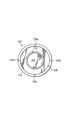
図1Aは2個のセンサーからのイメージデータを収集するためのシステム100のひとつの実施例の側面図を示す。システム100は物体110から反射された光またはエネルギー信号を受信しかつ光または入力信号からの情報を収集してディスプレイ142に物体110のイメージを生成する。システム100は光が通過する孔114を有する外部ケーシング112を含む。外部ケーシング112は直径8〜12cm(例えば、約10cm)で長さが12〜15cm(例えば、約14cm)の円筒のような適当な形状を有する。システム100は図1Bに示されるようなブレース124により外部ケーシング112へ結合された内部組立体116を含む。図1Bはブレース124によりケーシング112へ結合された内部組立体116の正面図を示す。
FIG. 1A shows a side view of one embodiment of a
図1Aを参照して、内部組立体116は光学要素118及びセンサー120を含み、各々は内部ケーシング117へ結合されている。内部ケーシング117は直径3〜6cm(例えば、約4.5cm)で長さが7〜10cm(例えば、約8cm)の円筒のような適当な形状を有する。光学要素118は物体110から反射された光をセンサー120上へ集束させる。光学要素118は例えば3〜5cm(例えば、約4cm)の半径及び20〜22mm(例えば、約22mm)の焦点距離を有するガラスまたはポリマーから成るレンズを含む。しかし、光学要素118は物体110からの光をセンサー120上へ集束させるためのあらゆる適当な光学要素または光学要素の組合せを含む。
Referring to FIG. 1A, the
センサー120は孔114を直接通過する(すなわち、遮るものがない経路を通る)物体110からの反射光を検出する。センサー120は光が物体110から孔114へ進む方向で光を受けるように配置される。センサー120は光のある種のエネルギー(例えば、赤外線エネルギー)を検出することもできる。センサー120は、例えばイメージ増強管またはセンサーのような光または信号のある特徴を強化することもできる。しかし、センサー120は例えば、長波長赤外線センサー、低光レベル電荷結合デバイス(LLLCCD)、または相補型金属酸化膜半導体(CMOS)センサーのようなあらゆる適当なセンサーから成る。概して増強管の設計は赤外線を受光しかつ可視光出力信号を生成するものであり、一方センサーの設計は可視光を受光するようなものである。
センサー120は受光した光に応答してセンサーデータセットS1を生成する。センサーデータセットS1は光の点に対応する画素に割り当てられた値を含み、その値は光の点に関連する明るさまたは色のようなイメージ情報を表す。センサー120はセンサーデータセットS1を融合モジュール140へ送信する。
The
システム100はまた反射面130及び132並びにセンサー134から成る外部組立体138を含む。反射面130及びセンサー134は外部ケーシング112へ結合され、反射面132は内部ケーシング117へ結合される。しかし、あらゆる適当な構成が使用可能であり、例えば外部組立体138はシュミットカセグラン・カタジオプトリック光学組立体、回折光学システム、または適当な構成の任意の組合せとして構成される。
反射面130は孔114を通じて物体110からの光を受光し、受光した光を反射する。反射面130は直径8〜10cm(例えば、約9cm)で焦点距離が24〜26mm(例えば、約25mm)の金属またはダイクロイックミラーから成る。しかし、反射面130は任意の材料から成り、孔114を通じて光を受光しかつその光を反射面132へ反射させるあらゆる適当な形状を有する。反射面132は反射面130からの光を受光し、受光した光を反射する。反射面132は直径7〜10cm(例えば、約8cm)で焦点距離が24〜26mm(例えば、約25mm)の金属またはダイクロイックミラーから成る。しかし反射面132は任意の材料から成り、反射面130からの光を受光しかつその光をセンサー134のレセプター領域133へ反射させるあらゆる適当な形状を有する。
The reflecting
センサー134のレセプター領域133は反射面132から反射された光を検出する。センサー134は例えば赤外線センサーまたはイメージ増強管センサーを含む。しかし、センサー134は例えば、長波長赤外線センサー、中間波長赤外線センサー、短波長赤外線センサー、低光レベル電荷結合素子(LLLCCD)または相補型金属酸化膜半導体(CMOS)センサー等のあらゆる適当なセンサーから成ることもできる。センサー134は受光した光に応答してセンサーデータS2を生成する。センサー134はセンサー120によって生成されたものと異なるタイプのデータセットを生成する。例えば、センサー120はデータセットを生成するべく受光した光の赤外線エネルギーを検出する赤外線センサーを含み、センサー134は異なるタイプのデータセットを生成するべく受光した光のある特徴を強化するイメージ増強センサーを含む。センサーデータセットS2は光の点に対応する画素に割り当てられた値を含み、該値は光の点に関連するイメージ情報を表す。センサー134は融合モジュール140へセンサーデータS2を送信する。
The
システム100は物体110からセンサー134のレセプター領域133への光路にほぼ沿って配置された中心軸線136を有する。センサー120及びセンサー134は中心軸線136にほぼ沿った点で光を受光するように実質的に同軸に配置されている。センサー120及びセンサー134は、内部組立体116の直径が反射面130の直径より小さくかつ内部組立体116が図1Bに示されるように反射面130に対してほぼ中心に配置されるように構成されている。図1Bはシステム100の正面図を示し、内部組立体116は反射面130の正面のほぼ中央に配置されている。図示された実施例において、センサー120及びセンサー134の構成により、センサー120及びセンサー134は最少の反射及び屈折エレメントにより同一の孔114からの光を受光することができ、その結果コンパクトな画像装置を与えることができる。
融合モジュール140はセンサー120及びセンサー134からそれぞれセンサーデータS1及びS2を受信する。融合モジュール140は融合データを生成するべくセンサーデータセットS1及びS2を融合させる。例えば、融合モジュール140は融合データを生成するべく光の同一点に対応するデータ単位または画素用のセンサーデータセットS1及びS2の値を結合する。融合モジュール140は例えば、デジタルイメージ処理、光学オーバレイまたはアナログビデオ処理のようなデータセットS1及びS2を融合するためのあらゆる適当な処理を使用する。
Fusion module 140 receives sensor data S1 and S2 from
図示された実施例において、センサー120及びセンサー134は同一の孔114を通じて受光した光を検出し、その結果センサー120及び134は物体110の同じ視点を記述する光を受光する。結果として、融合モジュール140は異なる視点を結合するデータ処理を実行する必要がない。付加的に、最少の反射及び屈折要素が使用されるため、センサー120及び134により検出された光はほとんど変更されない。結果として、融合モジュール140は複数の反射及び屈折要素による変更を補償するための処理を実行する必要がない。
In the illustrated embodiment,
ディスプレイ142は融合モジュール140から融合データを受信し、該融合データを使って物体110のイメージを生成する。ディスプレイ142は、パネルディスプレイ、接眼レンズディスプレイ、または眼付近ディスプレイフォーマットの、有機発光ダイオード(OLED)、ネマチック液晶ディスプレイ(LCD)、または電界放出ディスプレイ(FED)のようなイメージデータを表示するためのあらゆる適当な装置を含む。付加的に、ディスプレイ142は外部VGA若しくは他のディスプレイ、テレビ、USBタイプ接続、IEEE1394またはファイヤワイヤ型接続である。図示される実施例は2つのセンサー120及び134を有するが、本発明に係るシステムは図2で説明されるように任意の数のセンサーを含むことができる。
Display 142 receives the fusion data from fusion module 140 and uses the fusion data to generate an image of
図2はイメージデータを収集するための3個のセンサーを含むシステム200のひとつの実施例のブロック図である。システム200は外部ケーシング212へ結合された内部組立体216を含む。内部組立体は実質的に図1のシステム100と類似し、2個のセンサー120及び134を含む。外部組立体238は外部組立体138と実質的に類似する。すなわち、反射面130及び132と実質的に類似する反射面230及び232がそれぞれ内部組立体216及び外部ケーシング212へ結合される。付加的に、センサー134と実質的に類似するセンサー234が外部ケーシング212へ結合される。センサー120、134及び234は実質的に同軸である。融合モジュール140がセンサー120、134及び234へ接続され、ディスプレイ142が融合モジュール140へ接続される。
FIG. 2 is a block diagram of one embodiment of a
動作中、システム200は物体110からの反射光を受光する。内部組立体216は図1のシステム100と実質的に類似の方法でデータセットS1及びS2を生成する。センサー234はセンサー134と実質的に類似の方法で反射面230及び232からの反射光を受光しデータセットS3を生成する。融合モジュール140はデータセットS1、S2及びS3を受信し、該データセットを融合して融合データを生成する。ディスプレイ142は融合データを受信しかつ該融合データからイメージを生成する。さらに多くのセンサーがシステム200に付加されてもよい。
During operation,
図3は図1のシステム100を使ってイメージデータを収集するための方法のひとつの実施例を示すフローチャートである。当該方法は、物体110からの反射光が孔114により受光されるところの工程210で始まる。反射光は物体110のイメージを形成するのに使用されるイメージ情報を含む。工程212において、センサー120は受光した光を検出する。光をセンサー120へ集束させるために光学エレメント118が使用される。工程214において、センサー120は検出された光からデータセットS1を生成しかつデータセットS1を融合モジュール140へ送信する。例えば、センサー120は物体110から反射された赤外線を検出しかつ赤外線を記述するデータセットS1を生成してもよい。
FIG. 3 is a flowchart illustrating one embodiment of a method for collecting image data using the
工程216において、反射面130は物体110から光を受光しかつ受光した光を反射面132へ反射させる。工程218において、反射面132は反射光を受光しかつ受光した光をセンサー134へ反射させる。工程220において、センサー134は反射面132から反射された光を検出する。工程222において、センサー134は受光した光からデータセットS2を生成する。センサー134は物体110から受光した光のある特徴を強化するイメージ増強センサーを含み、強化された特徴を記述するデータセットを生成する。
In
工程224において、融合モジュール140はデータセットS1及びS2を受信しかつ受信したデータセットを融合して融合データを生成する。融合モジュール140は例えば光の同一点に対応する画素に対するデータセットS1及びS2からの値を組み合わせる。ディスプレイ142は融合データを受信し、その後工程226で物体110のイメージを表示する。イメージを表示した後、方法は終了する。
In step 224, the merge module 140 receives the data sets S1 and S2 and merges the received data sets to generate fused data. The fusion module 140 combines values from the data sets S1 and S2 for pixels corresponding to the same point of light, for example. Display 142 receives the fusion data and then displays an image of
特定的に図4を参照して、デジタルイメージ増強(I2)カメラ装置Cのひとつの実施例が多重スペクトル融合イメージ装置において使用される。 With particular reference to FIG. 4, one embodiment of a digital image enhancement (I2) camera device C is used in a multispectral fusion image device.
好適には、I2カメラCは以下のコンポーネント、すなわち
・ 観測すべき情景314から受光した光を増幅するイメージ増強管装置310
・ イメージ増強管310とデジタルイメージセンサー318の間を結合し、イメージ増強管310により生成された出力信号を伝達するための光学リレイ組立体または光ファイバー316
・ CMOSデバイスまたは電荷結合デバイス(CCD)のようなイメージセンサー318
・ イメージまたは関連データを所望により処理、強化及び/または出力するためのデジタル論理回路322
から成る。
Preferably, the I2 camera C has the following components: an image
An optical relay assembly or
An
Consists of.
付加的に、I2カメラCは、a)適応情景解析及び強化、b)自動不良センサー画素検出及び補正、及びc)外部または内部カメラ制御、同期またはタイミング、を制御、モニターまたは作用するための電子回路322を含む。デジタル論理回路322はセンサー318からの入力信号324を受信する。デジタル論理回路322はひとつまたはそれ以上の制御信号326を生成し、それはデジタル論理回路322の出力328を介してイメージ増強管310またはセンサー318のいずれかまたは両方へ送信される。さらに、デジタル論理回路322は付加的に制御プロセッササブシステム330を含み、それとデジタル論理回路322内部に設計された他のサブシステムとの間で信号332が伝達される。
Additionally, the I2 camera C is an electronic device for controlling, monitoring or acting on a) adaptive scene analysis and enhancement, b) automatic bad sensor pixel detection and correction, and c) external or internal camera control, synchronization or timing.
イメージ増強管組立体310は既知のイメージ増強管及びその動作用の典型的な付属電子回路を含む。
The image
適応情景解析及び強化:デジタル論理回路322はセンサー318により感知したイメージ320の全部または特定領域の連続輝度プロファイルを維持する。また、デジタル論理回路322は、全体または局所的な明るさ、空間周波数組成、または類似特性若しくは変数のようなさまざまなデータセット距離のプロファイルを維持する。その後以下のパラメータのいずれかまたはすべてがデジタル論理回路322またはユーザーによって自動的または手動で調節され、任意の情景に対する最適イメージを作る。
Adaptive scene analysis and enhancement: The
概して、自動最適化アルゴリズムは現イメージを調べ、それを入力情景条件に対する最適イメージパラメータに関する保存情報と比較する。例えば、明るい光の下で、カメラCはイメージ増強管310及び利得を減少させ、センサー318ADCに基準電圧を立ち上げ、出力情景内のある非常に明るい特徴部分をデジタル的に弱める。情景の明るさが減少するに従い、デジタル論理回路322は増強管の寿命及び信号対ノイズ比を維持するよう増強管利得を増加させる前にセンサー利得を増加させる。非常に暗い情景では、デジタル論理回路322はセンサーの利得を相当な動作限界まで上げ、増強管の利得を上げ、イメージ露光時間を増加させるようフレーム速度をできるだけ減少させる。
In general, the automatic optimization algorithm examines the current image and compares it with stored information about the optimal image parameters for the input scene conditions. For example, under bright light, camera C reduces
そのようなカメラは、さまざまな光条件に応答するイメージ増強管の事前知識から利益を得る。それぞれの場合、イメージパラメータは他の同様に取り付けられたカメラ以上のイメージ性能を達成するよう同時に調節される。 Such cameras benefit from prior knowledge of image intensifier tubes that respond to various light conditions. In each case, the image parameters are adjusted simultaneously to achieve image performance over other similarly mounted cameras.
別々に調節可能なパラメータの分類は以下の通りである。 The classification of parameters that can be adjusted separately is as follows.
1.センサーフレーム速度
センサー318のフレーム速度及び露光時間はダイナミックに変化する。例えば、薄暗い情景では、イメージ増強管の利得が減少(信号対ノイズ比は増加)し、フレーム速度が減少する。これにより付加的な入力光が無くてもイメージ品質が増加する。
1. Sensor frame speed The frame speed and exposure time of the
2.コントラスト/輝度/デジタルイメージ強化
デジタル論理回路322は感知した情景の画素の最適な輝度分布を数学的に決定することによりコントラストをダイナミックに増加させる。この自動強化は好適なユーザー輝度パラメータまたはプリセットイメージモード(例えば、晴れモード、霧モード等)により重み付けされる。デジタル論理回路は完全な入力輝度解像度を使用する。例えば、ひとつの実施例において、デジタル論理回路322は最小の2ビットを単純に打ち切る代わりに、10ビット入力データから8ビット出力データへディザ技術を使ってダイナミックにマッピングする。
2. Contrast / Luminance / Digital Image Enhancement The
3.デジタル的に制御されたイメージ増強管利得
増強管利得は、システム目標に応じて、寿命、信号対ノイズ比、または情景輝度を増加させるよう自動的または手動で調節される。
3. Digitally controlled image intensifier gain The intensifier gain is automatically or manually adjusted to increase lifetime, signal-to-noise ratio, or scene brightness, depending on system goals.
4.デジタル的に制御されたイメージ増強管ゲート
デジタル論理回路322は、イメージ増強管310をデジタルセンサー318露光時間と同期させる。これは、増強管露光頻度とセンサー露光頻度との差によって生じる情景の間に輝度の変動が存在しないことを保証する。この機能はグラフィカル・ユーザー・インターフェース(GUI)を通じてユーザーが制御可能である。
4). Digitally controlled image intensifier gate
5.電子的及び手動的に制御可能な、露光時間、利得等のデジタルセンサーアナログ参照及びデジタルセンサー制御
イメージセンサー318のイメージ及びタイミング制御パラメータは自動的に制御可能であり、すべての光条件に対して最適なイメージパラメータを与える。イメージ増強管310とイメージセンサー318パラメータとの間の最適なバランスがあらゆる外光条件に対して見つけられる。ユーザーはGUIを介してこれらのパラメータを手動で調節することができる。
5. Electronic and manually controllable digital sensor analog reference and digital sensor control such as exposure time, gain, etc. Image and timing control parameters of
自動不良センサー画素検出及び補正:付加的に、本実施例のI2カメラCはセンサー318に明るさ(または暗さ)を残す画素を補間によって自動的にデジタル検出及び補正する。
Automatic defective sensor pixel detection and correction: In addition, the I2 camera C of this embodiment automatically detects and corrects pixels that leave brightness (or darkness) in the
外部または内部カメラ同期及びタイミング:カメラCは、外部装置からの要求に応じて、所望のフレーム速度で連続的に動作し、デジタルデータを一度に一本のラインだけ出力334へ与えることができる。この能力により、単一のイメージ融合装置内で単一センサー及び複数センサーの両方に理想的なカメラCが作成される。
External or internal camera synchronization and timing: Camera C can continuously operate at the desired frame rate and provide digital data to
本発明の上記開示及び説明は例示に過ぎず、発明の思想から離れることなく図示された構成のサイズ、形状及び材料のさまざまな変更が可能である。 The above disclosure and description of the present invention are illustrative only, and various changes in the size, shape and material of the illustrated configuration are possible without departing from the spirit of the invention.
Claims (7)
受光した光を増幅するためのイメージ増強管と、
前記イメージ増強管からの増幅された光を受光しかつ電子的に変換するための複数のデジタルイメージセンサーであって、前記複数のデジタルイメージセンサーは、前記イメージ増強管の中心軸線に沿って別々に配置され、かつ、それぞれ異なる種類のデータを生成するところのデジタルイメージセンサーと、
前記イメージ増強管からの増幅された光を伝達するべく前記イメージ増強管と前記複数のデジタルイメージセンサーとの間にある光伝送組立体と、
イメージまたは関連データを処理するべく少なくとも前記複数のデジタルイメージセンサーと電子的に結合されたデジタル論理回路と、
を含むことを特徴とする装置。An image intensifying camera device for collecting image data,
An image intensifier tube for amplifying the received light;
A plurality of digital image sensors for receiving and electronically converting amplified light from the image intensifier tube , the plurality of digital image sensors separately along a central axis of the image intensifier tube; Digital image sensors that are arranged and generate different types of data ,
A light transmission assembly between the image intensifier tube and the plurality of digital image sensors to transmit amplified light from the image intensifier tube;
Digital logic circuitry electronically coupled to at least the plurality of digital image sensors to process images or related data;
The apparatus characterized by including.
Applications Claiming Priority (3)
| Application Number | Priority Date | Filing Date | Title |
|---|---|---|---|
| US31930902P | 2002-06-12 | 2002-06-12 | |
| PCT/US2003/017358 WO2003107088A2 (en) | 2002-06-01 | 2003-06-02 | Image intensification camera |
| US10/250,065 US7129462B2 (en) | 2002-06-12 | 2003-06-02 | Digitally enhanced image intensification camera |
Publications (2)
| Publication Number | Publication Date |
|---|---|
| JP2005530388A JP2005530388A (en) | 2005-10-06 |
| JP4331106B2 true JP4331106B2 (en) | 2009-09-16 |
Family
ID=29739161
Family Applications (1)
| Application Number | Title | Priority Date | Filing Date |
|---|---|---|---|
| JP2004513842A Expired - Fee Related JP4331106B2 (en) | 2002-06-12 | 2003-06-02 | Image enhancement camera |
Country Status (6)
| Country | Link |
|---|---|
| US (1) | US7129462B2 (en) |
| EP (2) | EP1512166A4 (en) |
| JP (1) | JP4331106B2 (en) |
| AU (1) | AU2003239931A1 (en) |
| IL (2) | IL165053A0 (en) |
| WO (1) | WO2003107088A2 (en) |
Families Citing this family (20)
| Publication number | Priority date | Publication date | Assignee | Title |
|---|---|---|---|---|
| US7331523B2 (en) * | 2001-07-13 | 2008-02-19 | Hand Held Products, Inc. | Adaptive optical image reader |
| US6970190B2 (en) * | 2002-06-12 | 2005-11-29 | Litton Systems, Inc. | Event synchronization for detector systems |
| US8134637B2 (en) * | 2004-01-28 | 2012-03-13 | Microsoft Corporation | Method and system to increase X-Y resolution in a depth (Z) camera using red, blue, green (RGB) sensing |
| US8139141B2 (en) * | 2004-01-28 | 2012-03-20 | Microsoft Corporation | Single chip red, green, blue, distance (RGB-Z) sensor |
| TWI279924B (en) * | 2005-05-17 | 2007-04-21 | Unimems Mfg Co Ltd | Dual band reflective thermal imaging system |
| FR2895146A1 (en) * | 2005-12-15 | 2007-06-22 | Eurofeedback Sa | Light amplifier device for nocturnal viewing apparatus of gun, has digital processing unit to control cyclic ratio for supplying photocathode, supply frequency of photocathode and gain adjustment and maximum current of screen |
| US7589309B2 (en) * | 2006-03-22 | 2009-09-15 | Ikonisys, Inc. | Imager system for an automated microscope |
| US8139142B2 (en) | 2006-06-01 | 2012-03-20 | Microsoft Corporation | Video manipulation of red, green, blue, distance (RGB-Z) data including segmentation, up-sampling, and background substitution techniques |
| WO2008085553A1 (en) * | 2006-08-25 | 2008-07-17 | Eliezer Jacob | Improved digital camera with non-uniform image resolution |
| CN102016392B (en) * | 2008-04-23 | 2014-03-12 | 皇家飞利浦电子股份有限公司 | Illumination device with improved remote control |
| DE112010004379T5 (en) * | 2009-11-13 | 2012-11-29 | Steven Donald Edelson | Surveillance and camera system and procedures |
| RU2446613C2 (en) * | 2010-05-26 | 2012-03-27 | Федеральное государственное унитарное предприятие "Российский Федеральный ядерный центр - Всероссийский научно-исследовательский институт экспериментальной физики" - ФГУП "РФЯЦ-ВНИИЭФ" | Device for recording images generated using radiation |
| US8717464B2 (en) | 2011-02-09 | 2014-05-06 | Blackberry Limited | Increased low light sensitivity for image sensors by combining quantum dot sensitivity to visible and infrared light |
| RU2515222C1 (en) * | 2012-11-20 | 2014-05-10 | Российская Федерация, от имени которой выступает Государственная корпорация по атомной энергии "Росатом"-Госкорпорация "Росатом" | Apparatus and methods of adjusting magnetic system for forming beam of protons in object plane of proton graphic system, matching magnetic induction of magnetooptical imaging system and monitoring adjustment of multiframe for recording proton images |
| US10121817B2 (en) | 2015-12-17 | 2018-11-06 | General Electric Company | Radiation detector for use as an image intensifier |
| GB2559733B (en) * | 2017-02-08 | 2022-10-05 | Sesanti Ltd | Long-range viewing apparatus |
| US10937622B2 (en) * | 2018-12-19 | 2021-03-02 | Elbit Systems Of America, Llc | Programmable performance configurations for night vision device |
| RU2708541C1 (en) * | 2019-03-18 | 2019-12-09 | Российская Федерация, от имени которой выступает Государственная корпорация по атомной энергии "Росатом" (Госкорпорация "Росатом") | Method of tuning a magnetooptical system of a protonographic complex |
| RU2727326C1 (en) * | 2019-12-16 | 2020-07-21 | Российская Федерация, от имени которой выступает Государственная корпорация по атомной энергии "Росатом" (Госкорпорация "Росатом") | Method of tuning a magnetooptical system of a protonographic complex (versions) |
| RU2750693C1 (en) * | 2020-07-27 | 2021-07-01 | Российская Федерация, от имени которой выступает Государственная корпорация по атомной энергии "Росатом" (Госкорпорация "Росатом") | Method for tuning magneto-optical system of protonographic complex |
Family Cites Families (28)
| Publication number | Priority date | Publication date | Assignee | Title |
|---|---|---|---|---|
| US1599A (en) * | 1840-05-12 | withet | ||
| DE3119751C2 (en) * | 1981-05-18 | 1985-09-26 | Siemens AG, 1000 Berlin und 8000 München | X-ray diagnostic facility |
| US4463252A (en) * | 1982-01-04 | 1984-07-31 | Baird Corporation | Night vision goggle system |
| US4602861A (en) * | 1982-12-23 | 1986-07-29 | Minolta Camera Kabushiki Kaisha | Auto-focusing system |
| FR2569510B1 (en) * | 1984-08-21 | 1986-11-21 | Thomson Csf | VIDEO SIGNAL CORRECTION DEVICE FOR FAST SIGNAL ACQUISITION AND ANALYSIS SYSTEM USING SLOT CAMERA |
| US4679068A (en) | 1985-07-25 | 1987-07-07 | General Electric Company | Composite visible/thermal-infrared imaging system |
| US4751571A (en) * | 1987-07-29 | 1988-06-14 | General Electric Company | Composite visible/thermal-infrared imaging apparatus |
| US4935817A (en) | 1988-12-22 | 1990-06-19 | Sperry Marine Inc. | Dual mode all - light level television camera |
| US5264961A (en) * | 1989-10-10 | 1993-11-23 | Unisys Corporation | Techniques for trapping beams of infra-red energy |
| US5035472A (en) * | 1990-06-20 | 1991-07-30 | The United States Of America As Represented By The Secretary Of The Army | Integrated multispectral man portable weapon sight |
| US5400383A (en) * | 1991-12-09 | 1995-03-21 | General Electric Company | Fluoroscopic imager with frame-filling apparatus |
| AU7687994A (en) * | 1993-08-20 | 1995-03-21 | Intevac, Inc. | Life extender and bright light protection for cctv camera system with image intensifier |
| JP2001518241A (en) * | 1995-06-07 | 2001-10-09 | ストリカー・コーポレーション | An imaging system that processes visible light energy and infrared light energy separately |
| USH1599H (en) | 1995-07-05 | 1996-10-01 | The United States Of America As Represented By The Secretary Of The Air Force | Synthetic-color night vision |
| US5872595A (en) * | 1995-08-16 | 1999-02-16 | Monahan; John F. | Methods and apparatus for providing wide range exposure control for image intensifier cameras |
| US5793322A (en) * | 1995-11-07 | 1998-08-11 | California Institute Of Technology | Successive approximation analog-to-digital converter using balanced charge integrating amplifiers |
| US6282261B1 (en) * | 1996-02-21 | 2001-08-28 | Lunar Corporation | Multi-mode x-ray image intensifier system |
| US5729376A (en) | 1996-07-01 | 1998-03-17 | The United States Of America As Represented By The Secretary Of The Army | Catadioptric multi-functional optical assembly |
| EP0894421A1 (en) | 1996-07-08 | 1999-02-03 | Koninklijke Philips Electronics N.V. | Correction of fixed pattern noise |
| US5729010A (en) * | 1996-09-11 | 1998-03-17 | The United States Of America As Represented By The Secretary Of The Air Force | Night vision device localized irradiance attenuation |
| US5959668A (en) * | 1996-09-26 | 1999-09-28 | Lockheed Martin Tactical Defense Systems, Inc. | Automatic exposure and gain control for a sensor using video feedback |
| US5847499A (en) * | 1997-01-31 | 1998-12-08 | Sunnybrook Hospital | Apparatus for generating multiple X-ray images of an object from a single X-ray exposure |
| EP0978008B1 (en) * | 1997-04-09 | 2004-03-31 | Richardson Technologies Inc. | Color translating uv microscope |
| US7053928B1 (en) | 2000-03-20 | 2006-05-30 | Litton Systems, Inc. | Method and system for combining multi-spectral images of a scene |
| US6985181B2 (en) * | 2000-05-09 | 2006-01-10 | Pixim, Inc. | CMOS sensor array with a memory interface |
| US6747258B2 (en) * | 2001-10-09 | 2004-06-08 | Itt Manufacturing Enterprises, Inc. | Intensified hybrid solid-state sensor with an insulating layer |
| US6560029B1 (en) | 2001-12-21 | 2003-05-06 | Itt Manufacturing Enterprises, Inc. | Video enhanced night vision goggle |
| US6707054B2 (en) * | 2002-03-21 | 2004-03-16 | Eastman Kodak Company | Scannerless range imaging system having high dynamic range |
-
2003
- 2003-06-02 AU AU2003239931A patent/AU2003239931A1/en not_active Abandoned
- 2003-06-02 US US10/250,065 patent/US7129462B2/en not_active Expired - Lifetime
- 2003-06-02 WO PCT/US2003/017358 patent/WO2003107088A2/en active Application Filing
- 2003-06-02 IL IL16505303A patent/IL165053A0/en unknown
- 2003-06-02 JP JP2004513842A patent/JP4331106B2/en not_active Expired - Fee Related
- 2003-06-02 EP EP03734342A patent/EP1512166A4/en not_active Withdrawn
- 2003-06-02 EP EP12007851A patent/EP2562785A1/en not_active Withdrawn
-
2004
- 2004-11-04 IL IL165053A patent/IL165053A/en not_active IP Right Cessation
Also Published As
| Publication number | Publication date |
|---|---|
| WO2003107088A8 (en) | 2005-02-17 |
| US7129462B2 (en) | 2006-10-31 |
| AU2003239931A8 (en) | 2003-12-31 |
| US20030230707A1 (en) | 2003-12-18 |
| IL165053A0 (en) | 2005-12-18 |
| EP1512166A4 (en) | 2009-12-09 |
| EP2562785A1 (en) | 2013-02-27 |
| EP1512166A2 (en) | 2005-03-09 |
| IL165053A (en) | 2010-06-30 |
| WO2003107088A3 (en) | 2004-02-26 |
| WO2003107088A2 (en) | 2003-12-24 |
| AU2003239931A1 (en) | 2003-12-31 |
| JP2005530388A (en) | 2005-10-06 |
Similar Documents
| Publication | Publication Date | Title |
|---|---|---|
| JP4331106B2 (en) | Image enhancement camera | |
| JP5165625B2 (en) | InGaAs image enhancement camera | |
| US9648255B2 (en) | Multi-modal optoelectronic vision system and uses thereof | |
| KR100415464B1 (en) | IR camera | |
| US20180109739A1 (en) | Apparatus, system and method of modifying an image sensor to achieve hyperspectral imaging in low light | |
| US7646406B2 (en) | Image taking apparatus | |
| EP1410419B1 (en) | Gathering image data using multiple sensors | |
| JP4369365B2 (en) | Event synchronization device for detection system | |
| JP2012182626A (en) | Imaging apparatus | |
| JP2008017079A (en) | Video camera | |
| WO1990005426A1 (en) | T.v. surveillance camera | |
| FR2838016A1 (en) | PROCESS FOR REAL-TIME PROCESSING OF AN IMAGE REPRESENTATIVE SIGNAL | |
| KR101586698B1 (en) | Surveillance camera | |
| JP2004229034A (en) | Day/night camera incorporating infrared illumination | |
| JP4530149B2 (en) | High dynamic range camera system | |
| KR101475468B1 (en) | Infrared camera system with infrared LED | |
| KR20060104566A (en) | Cctv camera for day and night with ir injection method | |
| KR20010027312A (en) | CCD camera in combination with zoom lens | |
| KR101613605B1 (en) | Video Control System For Color Camera Having Radiation Tolerant | |
| WO2020021674A1 (en) | Display system and display system control method | |
| Vermeulen | Light sources and closed-circuit television | |
| Furgal | Video Cameras. | |
| JPS62248382A (en) | Night vision device | |
| KR20160006036A (en) | Surveillance camera | |
| JP2011160320A (en) | Video camera and video monitoring system using the same |
Legal Events
| Date | Code | Title | Description |
|---|---|---|---|
| A621 | Written request for application examination |
Free format text: JAPANESE INTERMEDIATE CODE: A621 Effective date: 20060125 |
|
| RD04 | Notification of resignation of power of attorney |
Free format text: JAPANESE INTERMEDIATE CODE: A7424 Effective date: 20080519 |
|
| A977 | Report on retrieval |
Free format text: JAPANESE INTERMEDIATE CODE: A971007 Effective date: 20080710 |
|
| A131 | Notification of reasons for refusal |
Free format text: JAPANESE INTERMEDIATE CODE: A131 Effective date: 20080717 |
|
| A521 | Request for written amendment filed |
Free format text: JAPANESE INTERMEDIATE CODE: A523 Effective date: 20081017 |
|
| A02 | Decision of refusal |
Free format text: JAPANESE INTERMEDIATE CODE: A02 Effective date: 20081118 |
|
| A521 | Request for written amendment filed |
Free format text: JAPANESE INTERMEDIATE CODE: A523 Effective date: 20090302 |
|
| A521 | Request for written amendment filed |
Free format text: JAPANESE INTERMEDIATE CODE: A523 Effective date: 20090324 |
|
| A911 | Transfer to examiner for re-examination before appeal (zenchi) |
Free format text: JAPANESE INTERMEDIATE CODE: A911 Effective date: 20090331 |
|
| TRDD | Decision of grant or rejection written | ||
| A01 | Written decision to grant a patent or to grant a registration (utility model) |
Free format text: JAPANESE INTERMEDIATE CODE: A01 Effective date: 20090611 |
|
| A01 | Written decision to grant a patent or to grant a registration (utility model) |
Free format text: JAPANESE INTERMEDIATE CODE: A01 |
|
| A61 | First payment of annual fees (during grant procedure) |
Free format text: JAPANESE INTERMEDIATE CODE: A61 Effective date: 20090617 |
|
| R150 | Certificate of patent or registration of utility model |
Free format text: JAPANESE INTERMEDIATE CODE: R150 |
|
| FPAY | Renewal fee payment (event date is renewal date of database) |
Free format text: PAYMENT UNTIL: 20120626 Year of fee payment: 3 |
|
| FPAY | Renewal fee payment (event date is renewal date of database) |
Free format text: PAYMENT UNTIL: 20130626 Year of fee payment: 4 |
|
| LAPS | Cancellation because of no payment of annual fees |