JP4330539B2 - Self-cleaning spray nozzle - Google Patents
Self-cleaning spray nozzle Download PDFInfo
- Publication number
- JP4330539B2 JP4330539B2 JP2004561101A JP2004561101A JP4330539B2 JP 4330539 B2 JP4330539 B2 JP 4330539B2 JP 2004561101 A JP2004561101 A JP 2004561101A JP 2004561101 A JP2004561101 A JP 2004561101A JP 4330539 B2 JP4330539 B2 JP 4330539B2
- Authority
- JP
- Japan
- Prior art keywords
- spray nozzle
- temperature
- carrier
- composition
- nozzle
- Prior art date
- Legal status (The legal status is an assumption and is not a legal conclusion. Google has not performed a legal analysis and makes no representation as to the accuracy of the status listed.)
- Expired - Lifetime
Links
- 239000007921 spray Substances 0.000 title claims abstract description 146
- 238000004140 cleaning Methods 0.000 title abstract description 14
- 230000002776 aggregation Effects 0.000 claims abstract description 38
- 238000005054 agglomeration Methods 0.000 claims abstract description 27
- 239000000203 mixture Substances 0.000 claims description 155
- 238000002844 melting Methods 0.000 claims description 49
- 230000008018 melting Effects 0.000 claims description 49
- 239000007788 liquid Substances 0.000 claims description 21
- 229910001220 stainless steel Inorganic materials 0.000 claims description 12
- 239000010935 stainless steel Substances 0.000 claims description 12
- 238000005507 spraying Methods 0.000 claims description 7
- 238000011144 upstream manufacturing Methods 0.000 claims description 5
- 238000007599 discharging Methods 0.000 claims description 3
- 238000002156 mixing Methods 0.000 claims description 3
- 239000000758 substrate Substances 0.000 claims description 2
- 239000013543 active substance Substances 0.000 abstract description 45
- 239000011236 particulate material Substances 0.000 abstract description 27
- 239000002245 particle Substances 0.000 abstract description 24
- 238000000034 method Methods 0.000 abstract description 23
- 239000008194 pharmaceutical composition Substances 0.000 abstract description 12
- 230000012010 growth Effects 0.000 abstract description 7
- 238000002144 chemical decomposition reaction Methods 0.000 abstract description 2
- 238000002360 preparation method Methods 0.000 abstract 2
- 229920001223 polyethylene glycol Polymers 0.000 description 64
- -1 polyethylene Polymers 0.000 description 44
- 239000008187 granular material Substances 0.000 description 31
- 239000000463 material Substances 0.000 description 24
- 239000002202 Polyethylene glycol Substances 0.000 description 23
- XLYOFNOQVPJJNP-UHFFFAOYSA-N water Substances O XLYOFNOQVPJJNP-UHFFFAOYSA-N 0.000 description 22
- GUBGYTABKSRVRQ-XLOQQCSPSA-N Alpha-Lactose Chemical compound O[C@@H]1[C@@H](O)[C@@H](O)[C@@H](CO)O[C@H]1O[C@@H]1[C@@H](CO)O[C@H](O)[C@H](O)[C@H]1O GUBGYTABKSRVRQ-XLOQQCSPSA-N 0.000 description 20
- GUBGYTABKSRVRQ-QKKXKWKRSA-N Lactose Natural products OC[C@H]1O[C@@H](O[C@H]2[C@H](O)[C@@H](O)C(O)O[C@@H]2CO)[C@H](O)[C@@H](O)[C@H]1O GUBGYTABKSRVRQ-QKKXKWKRSA-N 0.000 description 19
- 229920002584 Polyethylene Glycol 6000 Polymers 0.000 description 19
- 239000008101 lactose Substances 0.000 description 19
- 229960001375 lactose Drugs 0.000 description 19
- 238000004519 manufacturing process Methods 0.000 description 18
- 239000000546 pharmaceutical excipient Substances 0.000 description 17
- 239000003826 tablet Substances 0.000 description 16
- 229940079593 drug Drugs 0.000 description 15
- 239000003814 drug Substances 0.000 description 15
- 239000008118 PEG 6000 Substances 0.000 description 14
- 235000014113 dietary fatty acids Nutrition 0.000 description 14
- 239000000194 fatty acid Substances 0.000 description 14
- 229930195729 fatty acid Natural products 0.000 description 14
- 239000000047 product Substances 0.000 description 14
- 239000000126 substance Substances 0.000 description 14
- 239000007787 solid Substances 0.000 description 13
- 239000004094 surface-active agent Substances 0.000 description 13
- 230000001225 therapeutic effect Effects 0.000 description 13
- DNIAPMSPPWPWGF-UHFFFAOYSA-N Propylene glycol Chemical compound CC(O)CO DNIAPMSPPWPWGF-UHFFFAOYSA-N 0.000 description 11
- 238000004220 aggregation Methods 0.000 description 11
- 238000000889 atomisation Methods 0.000 description 11
- 239000006199 nebulizer Substances 0.000 description 11
- 239000011230 binding agent Substances 0.000 description 10
- FUFJGUQYACFECW-UHFFFAOYSA-L calcium hydrogenphosphate Chemical compound [Ca+2].OP([O-])([O-])=O FUFJGUQYACFECW-UHFFFAOYSA-L 0.000 description 10
- 238000010438 heat treatment Methods 0.000 description 10
- 230000000069 prophylactic effect Effects 0.000 description 10
- 235000019700 dicalcium phosphate Nutrition 0.000 description 9
- 229920001983 poloxamer Polymers 0.000 description 9
- PEDCQBHIVMGVHV-UHFFFAOYSA-N Glycerol Natural products OCC(O)CO PEDCQBHIVMGVHV-UHFFFAOYSA-N 0.000 description 8
- LYCAIKOWRPUZTN-UHFFFAOYSA-N Ethylene glycol Chemical compound OCCO LYCAIKOWRPUZTN-UHFFFAOYSA-N 0.000 description 7
- 229910000593 SAF 2205 Inorganic materials 0.000 description 7
- 229920006362 Teflon® Polymers 0.000 description 7
- WMGSQTMJHBYJMQ-UHFFFAOYSA-N aluminum;magnesium;silicate Chemical compound [Mg+2].[Al+3].[O-][Si]([O-])([O-])[O-] WMGSQTMJHBYJMQ-UHFFFAOYSA-N 0.000 description 7
- 229940093429 polyethylene glycol 6000 Drugs 0.000 description 7
- 239000004809 Teflon Substances 0.000 description 6
- 239000002537 cosmetic Substances 0.000 description 6
- 238000009826 distribution Methods 0.000 description 6
- 150000004665 fatty acids Chemical class 0.000 description 6
- 239000012051 hydrophobic carrier Substances 0.000 description 6
- 239000000314 lubricant Substances 0.000 description 6
- 230000008569 process Effects 0.000 description 6
- WSVLPVUVIUVCRA-KPKNDVKVSA-N Alpha-lactose monohydrate Chemical compound O.O[C@@H]1[C@@H](O)[C@@H](O)[C@@H](CO)O[C@H]1O[C@@H]1[C@@H](CO)O[C@H](O)[C@H](O)[C@H]1O WSVLPVUVIUVCRA-KPKNDVKVSA-N 0.000 description 5
- 108091006146 Channels Proteins 0.000 description 5
- 229920002560 Polyethylene Glycol 3000 Polymers 0.000 description 5
- 239000003795 chemical substances by application Substances 0.000 description 5
- 230000008021 deposition Effects 0.000 description 5
- JAUGGEIKQIHSMF-UHFFFAOYSA-N dialuminum;dimagnesium;dioxido(oxo)silane;oxygen(2-);hydrate Chemical compound O.[O-2].[O-2].[Mg+2].[Mg+2].[Al+3].[Al+3].[O-][Si]([O-])=O.[O-][Si]([O-])=O.[O-][Si]([O-])=O JAUGGEIKQIHSMF-UHFFFAOYSA-N 0.000 description 5
- 239000012052 hydrophilic carrier Substances 0.000 description 5
- 238000012545 processing Methods 0.000 description 5
- 239000002904 solvent Substances 0.000 description 5
- JNYAEWCLZODPBN-JGWLITMVSA-N (2r,3r,4s)-2-[(1r)-1,2-dihydroxyethyl]oxolane-3,4-diol Chemical class OC[C@@H](O)[C@H]1OC[C@H](O)[C@H]1O JNYAEWCLZODPBN-JGWLITMVSA-N 0.000 description 4
- VTYYLEPIZMXCLO-UHFFFAOYSA-L Calcium carbonate Chemical compound [Ca+2].[O-]C([O-])=O VTYYLEPIZMXCLO-UHFFFAOYSA-L 0.000 description 4
- FBPFZTCFMRRESA-JGWLITMVSA-N D-glucitol Chemical compound OC[C@H](O)[C@@H](O)[C@H](O)[C@H](O)CO FBPFZTCFMRRESA-JGWLITMVSA-N 0.000 description 4
- 241001465754 Metazoa Species 0.000 description 4
- 229920000168 Microcrystalline cellulose Polymers 0.000 description 4
- 229920000881 Modified starch Polymers 0.000 description 4
- RVGRUAULSDPKGF-UHFFFAOYSA-N Poloxamer Chemical compound C1CO1.CC1CO1 RVGRUAULSDPKGF-UHFFFAOYSA-N 0.000 description 4
- RJKFOVLPORLFTN-LEKSSAKUSA-N Progesterone Chemical compound C1CC2=CC(=O)CC[C@]2(C)[C@@H]2[C@@H]1[C@@H]1CC[C@H](C(=O)C)[C@@]1(C)CC2 RJKFOVLPORLFTN-LEKSSAKUSA-N 0.000 description 4
- 229920002472 Starch Polymers 0.000 description 4
- MUMGGOZAMZWBJJ-DYKIIFRCSA-N Testostosterone Chemical compound O=C1CC[C@]2(C)[C@H]3CC[C@](C)([C@H](CC4)O)[C@@H]4[C@@H]3CCC2=C1 MUMGGOZAMZWBJJ-DYKIIFRCSA-N 0.000 description 4
- DPXJVFZANSGRMM-UHFFFAOYSA-N acetic acid;2,3,4,5,6-pentahydroxyhexanal;sodium Chemical compound [Na].CC(O)=O.OCC(O)C(O)C(O)C(O)C=O DPXJVFZANSGRMM-UHFFFAOYSA-N 0.000 description 4
- 239000003963 antioxidant agent Substances 0.000 description 4
- 235000006708 antioxidants Nutrition 0.000 description 4
- 229920001400 block copolymer Polymers 0.000 description 4
- 238000009529 body temperature measurement Methods 0.000 description 4
- 239000001506 calcium phosphate Substances 0.000 description 4
- OSGAYBCDTDRGGQ-UHFFFAOYSA-L calcium sulfate Chemical compound [Ca+2].[O-]S([O-])(=O)=O OSGAYBCDTDRGGQ-UHFFFAOYSA-L 0.000 description 4
- 239000000969 carrier Substances 0.000 description 4
- 239000004359 castor oil Substances 0.000 description 4
- 235000019438 castor oil Nutrition 0.000 description 4
- 238000004581 coalescence Methods 0.000 description 4
- 238000000576 coating method Methods 0.000 description 4
- 150000002148 esters Chemical class 0.000 description 4
- ZEMPKEQAKRGZGQ-XOQCFJPHSA-N glycerol triricinoleate Natural products CCCCCC[C@@H](O)CC=CCCCCCCCC(=O)OC[C@@H](COC(=O)CCCCCCCC=CC[C@@H](O)CCCCCC)OC(=O)CCCCCCCC=CC[C@H](O)CCCCCC ZEMPKEQAKRGZGQ-XOQCFJPHSA-N 0.000 description 4
- NOESYZHRGYRDHS-UHFFFAOYSA-N insulin Chemical compound N1C(=O)C(NC(=O)C(CCC(N)=O)NC(=O)C(CCC(O)=O)NC(=O)C(C(C)C)NC(=O)C(NC(=O)CN)C(C)CC)CSSCC(C(NC(CO)C(=O)NC(CC(C)C)C(=O)NC(CC=2C=CC(O)=CC=2)C(=O)NC(CCC(N)=O)C(=O)NC(CC(C)C)C(=O)NC(CCC(O)=O)C(=O)NC(CC(N)=O)C(=O)NC(CC=2C=CC(O)=CC=2)C(=O)NC(CSSCC(NC(=O)C(C(C)C)NC(=O)C(CC(C)C)NC(=O)C(CC=2C=CC(O)=CC=2)NC(=O)C(CC(C)C)NC(=O)C(C)NC(=O)C(CCC(O)=O)NC(=O)C(C(C)C)NC(=O)C(CC(C)C)NC(=O)C(CC=2NC=NC=2)NC(=O)C(CO)NC(=O)CNC2=O)C(=O)NCC(=O)NC(CCC(O)=O)C(=O)NC(CCCNC(N)=N)C(=O)NCC(=O)NC(CC=3C=CC=CC=3)C(=O)NC(CC=3C=CC=CC=3)C(=O)NC(CC=3C=CC(O)=CC=3)C(=O)NC(C(C)O)C(=O)N3C(CCC3)C(=O)NC(CCCCN)C(=O)NC(C)C(O)=O)C(=O)NC(CC(N)=O)C(O)=O)=O)NC(=O)C(C(C)CC)NC(=O)C(CO)NC(=O)C(C(C)O)NC(=O)C1CSSCC2NC(=O)C(CC(C)C)NC(=O)C(NC(=O)C(CCC(N)=O)NC(=O)C(CC(N)=O)NC(=O)C(NC(=O)C(N)CC=1C=CC=CC=1)C(C)C)CC1=CN=CN1 NOESYZHRGYRDHS-UHFFFAOYSA-N 0.000 description 4
- HQKMJHAJHXVSDF-UHFFFAOYSA-L magnesium stearate Chemical compound [Mg+2].CCCCCCCCCCCCCCCCCC([O-])=O.CCCCCCCCCCCCCCCCCC([O-])=O HQKMJHAJHXVSDF-UHFFFAOYSA-L 0.000 description 4
- 239000000155 melt Substances 0.000 description 4
- 235000019813 microcrystalline cellulose Nutrition 0.000 description 4
- 239000008108 microcrystalline cellulose Substances 0.000 description 4
- 229940016286 microcrystalline cellulose Drugs 0.000 description 4
- GLDOVTGHNKAZLK-UHFFFAOYSA-N octadecan-1-ol Chemical compound CCCCCCCCCCCCCCCCCCO GLDOVTGHNKAZLK-UHFFFAOYSA-N 0.000 description 4
- QIQXTHQIDYTFRH-UHFFFAOYSA-N octadecanoic acid Chemical compound CCCCCCCCCCCCCCCCCC(O)=O QIQXTHQIDYTFRH-UHFFFAOYSA-N 0.000 description 4
- 229920003023 plastic Polymers 0.000 description 4
- 239000004033 plastic Substances 0.000 description 4
- 229920000223 polyglycerol Polymers 0.000 description 4
- 229920000642 polymer Polymers 0.000 description 4
- 239000000843 powder Substances 0.000 description 4
- 238000001878 scanning electron micrograph Methods 0.000 description 4
- 235000019698 starch Nutrition 0.000 description 4
- 229940032147 starch Drugs 0.000 description 4
- 239000008107 starch Substances 0.000 description 4
- 239000001993 wax Substances 0.000 description 4
- WWYNJERNGUHSAO-XUDSTZEESA-N (+)-Norgestrel Chemical compound O=C1CC[C@@H]2[C@H]3CC[C@](CC)([C@](CC4)(O)C#C)[C@@H]4[C@@H]3CCC2=C1 WWYNJERNGUHSAO-XUDSTZEESA-N 0.000 description 3
- FBPFZTCFMRRESA-FSIIMWSLSA-N D-Glucitol Natural products OC[C@H](O)[C@H](O)[C@@H](O)[C@H](O)CO FBPFZTCFMRRESA-FSIIMWSLSA-N 0.000 description 3
- FBPFZTCFMRRESA-KVTDHHQDSA-N D-Mannitol Chemical compound OC[C@@H](O)[C@@H](O)[C@H](O)[C@H](O)CO FBPFZTCFMRRESA-KVTDHHQDSA-N 0.000 description 3
- 239000004375 Dextrin Substances 0.000 description 3
- 229920001353 Dextrin Polymers 0.000 description 3
- WQZGKKKJIJFFOK-GASJEMHNSA-N Glucose Natural products OC[C@H]1OC(O)[C@H](O)[C@@H](O)[C@@H]1O WQZGKKKJIJFFOK-GASJEMHNSA-N 0.000 description 3
- 229920002153 Hydroxypropyl cellulose Polymers 0.000 description 3
- 229930195725 Mannitol Natural products 0.000 description 3
- 229920003091 Methocel™ Polymers 0.000 description 3
- WHNWPMSKXPGLAX-UHFFFAOYSA-N N-Vinyl-2-pyrrolidone Chemical compound C=CN1CCCC1=O WHNWPMSKXPGLAX-UHFFFAOYSA-N 0.000 description 3
- 235000021355 Stearic acid Nutrition 0.000 description 3
- 229910000831 Steel Inorganic materials 0.000 description 3
- CZMRCDWAGMRECN-UGDNZRGBSA-N Sucrose Chemical compound O[C@H]1[C@H](O)[C@@H](CO)O[C@@]1(CO)O[C@@H]1[C@H](O)[C@@H](O)[C@H](O)[C@@H](CO)O1 CZMRCDWAGMRECN-UGDNZRGBSA-N 0.000 description 3
- 229930006000 Sucrose Natural products 0.000 description 3
- 235000010443 alginic acid Nutrition 0.000 description 3
- 229920000615 alginic acid Polymers 0.000 description 3
- 239000003125 aqueous solvent Substances 0.000 description 3
- 235000013871 bee wax Nutrition 0.000 description 3
- 239000012166 beeswax Substances 0.000 description 3
- 239000002775 capsule Substances 0.000 description 3
- 210000004027 cell Anatomy 0.000 description 3
- 239000001913 cellulose Substances 0.000 description 3
- KRKNYBCHXYNGOX-UHFFFAOYSA-N citric acid Chemical compound OC(=O)CC(O)(C(O)=O)CC(O)=O KRKNYBCHXYNGOX-UHFFFAOYSA-N 0.000 description 3
- 239000011248 coating agent Substances 0.000 description 3
- 235000019425 dextrin Nutrition 0.000 description 3
- 239000003085 diluting agent Substances 0.000 description 3
- 239000006185 dispersion Substances 0.000 description 3
- 229940088679 drug related substance Drugs 0.000 description 3
- 150000002191 fatty alcohols Chemical class 0.000 description 3
- 125000005456 glyceride group Chemical group 0.000 description 3
- 239000003102 growth factor Substances 0.000 description 3
- IPCSVZSSVZVIGE-UHFFFAOYSA-N hexadecanoic acid Chemical compound CCCCCCCCCCCCCCCC(O)=O IPCSVZSSVZVIGE-UHFFFAOYSA-N 0.000 description 3
- 239000001863 hydroxypropyl cellulose Substances 0.000 description 3
- 235000010979 hydroxypropyl methyl cellulose Nutrition 0.000 description 3
- 239000001866 hydroxypropyl methyl cellulose Substances 0.000 description 3
- 229920003088 hydroxypropyl methyl cellulose Polymers 0.000 description 3
- UFVKGYZPFZQRLF-UHFFFAOYSA-N hydroxypropyl methyl cellulose Chemical compound OC1C(O)C(OC)OC(CO)C1OC1C(O)C(O)C(OC2C(C(O)C(OC3C(C(O)C(O)C(CO)O3)O)C(CO)O2)O)C(CO)O1 UFVKGYZPFZQRLF-UHFFFAOYSA-N 0.000 description 3
- 229960004400 levonorgestrel Drugs 0.000 description 3
- 230000033001 locomotion Effects 0.000 description 3
- 238000012423 maintenance Methods 0.000 description 3
- 239000000594 mannitol Substances 0.000 description 3
- 235000010355 mannitol Nutrition 0.000 description 3
- 238000007909 melt granulation Methods 0.000 description 3
- OQCDKBAXFALNLD-UHFFFAOYSA-N octadecanoic acid Natural products CCCCCCCC(C)CCCCCCCCC(O)=O OQCDKBAXFALNLD-UHFFFAOYSA-N 0.000 description 3
- 239000003921 oil Substances 0.000 description 3
- 235000019198 oils Nutrition 0.000 description 3
- ZQPPMHVWECSIRJ-KTKRTIGZSA-N oleic acid Chemical compound CCCCCCCC\C=C/CCCCCCCC(O)=O ZQPPMHVWECSIRJ-KTKRTIGZSA-N 0.000 description 3
- 102000004196 processed proteins & peptides Human genes 0.000 description 3
- 108090000765 processed proteins & peptides Proteins 0.000 description 3
- 108090000623 proteins and genes Proteins 0.000 description 3
- 235000010356 sorbitol Nutrition 0.000 description 3
- 239000000600 sorbitol Substances 0.000 description 3
- 239000003381 stabilizer Substances 0.000 description 3
- 239000007858 starting material Substances 0.000 description 3
- 239000008117 stearic acid Substances 0.000 description 3
- 239000010959 steel Substances 0.000 description 3
- 230000001954 sterilising effect Effects 0.000 description 3
- 238000004659 sterilization and disinfection Methods 0.000 description 3
- 239000005720 sucrose Substances 0.000 description 3
- TUNFSRHWOTWDNC-HKGQFRNVSA-N tetradecanoic acid Chemical compound CCCCCCCCCCCCC[14C](O)=O TUNFSRHWOTWDNC-HKGQFRNVSA-N 0.000 description 3
- QORWJWZARLRLPR-UHFFFAOYSA-H tricalcium bis(phosphate) Chemical compound [Ca+2].[Ca+2].[Ca+2].[O-]P([O-])([O-])=O.[O-]P([O-])([O-])=O QORWJWZARLRLPR-UHFFFAOYSA-H 0.000 description 3
- 235000015112 vegetable and seed oil Nutrition 0.000 description 3
- 239000008158 vegetable oil Substances 0.000 description 3
- 235000013343 vitamin Nutrition 0.000 description 3
- 239000011782 vitamin Substances 0.000 description 3
- 229940088594 vitamin Drugs 0.000 description 3
- 229930003231 vitamin Natural products 0.000 description 3
- BLSQLHNBWJLIBQ-OZXSUGGESA-N (2R,4S)-terconazole Chemical compound C1CN(C(C)C)CCN1C(C=C1)=CC=C1OC[C@@H]1O[C@@](CN2N=CN=C2)(C=2C(=CC(Cl)=CC=2)Cl)OC1 BLSQLHNBWJLIBQ-OZXSUGGESA-N 0.000 description 2
- ZORQXIQZAOLNGE-UHFFFAOYSA-N 1,1-difluorocyclohexane Chemical compound FC1(F)CCCCC1 ZORQXIQZAOLNGE-UHFFFAOYSA-N 0.000 description 2
- VBICKXHEKHSIBG-UHFFFAOYSA-N 1-monostearoylglycerol Chemical compound CCCCCCCCCCCCCCCCCC(=O)OCC(O)CO VBICKXHEKHSIBG-UHFFFAOYSA-N 0.000 description 2
- VOXZDWNPVJITMN-ZBRFXRBCSA-N 17β-estradiol Chemical compound OC1=CC=C2[C@H]3CC[C@](C)([C@H](CC4)O)[C@@H]4[C@@H]3CCC2=C1 VOXZDWNPVJITMN-ZBRFXRBCSA-N 0.000 description 2
- SGTNSNPWRIOYBX-UHFFFAOYSA-N 2-(3,4-dimethoxyphenyl)-5-{[2-(3,4-dimethoxyphenyl)ethyl](methyl)amino}-2-(propan-2-yl)pentanenitrile Chemical compound C1=C(OC)C(OC)=CC=C1CCN(C)CCCC(C#N)(C(C)C)C1=CC=C(OC)C(OC)=C1 SGTNSNPWRIOYBX-UHFFFAOYSA-N 0.000 description 2
- XZIIFPSPUDAGJM-UHFFFAOYSA-N 6-chloro-2-n,2-n-diethylpyrimidine-2,4-diamine Chemical compound CCN(CC)C1=NC(N)=CC(Cl)=N1 XZIIFPSPUDAGJM-UHFFFAOYSA-N 0.000 description 2
- 235000019489 Almond oil Nutrition 0.000 description 2
- 239000005995 Aluminium silicate Substances 0.000 description 2
- CIWBSHSKHKDKBQ-JLAZNSOCSA-N Ascorbic acid Chemical compound OC[C@H](O)[C@H]1OC(=O)C(O)=C1O CIWBSHSKHKDKBQ-JLAZNSOCSA-N 0.000 description 2
- 102000007644 Colony-Stimulating Factors Human genes 0.000 description 2
- 108010071942 Colony-Stimulating Factors Proteins 0.000 description 2
- 229920002261 Corn starch Polymers 0.000 description 2
- 229920002785 Croscarmellose sodium Polymers 0.000 description 2
- ULGZDMOVFRHVEP-RWJQBGPGSA-N Erythromycin Chemical compound O([C@@H]1[C@@H](C)C(=O)O[C@@H]([C@@]([C@H](O)[C@@H](C)C(=O)[C@H](C)C[C@@](C)(O)[C@H](O[C@H]2[C@@H]([C@H](C[C@@H](C)O2)N(C)C)O)[C@H]1C)(C)O)CC)[C@H]1C[C@@](C)(OC)[C@@H](O)[C@H](C)O1 ULGZDMOVFRHVEP-RWJQBGPGSA-N 0.000 description 2
- 102000003951 Erythropoietin Human genes 0.000 description 2
- 108090000394 Erythropoietin Proteins 0.000 description 2
- 102000004877 Insulin Human genes 0.000 description 2
- 108090001061 Insulin Proteins 0.000 description 2
- CPLXHLVBOLITMK-UHFFFAOYSA-N Magnesium oxide Chemical compound [Mg]=O CPLXHLVBOLITMK-UHFFFAOYSA-N 0.000 description 2
- 239000004368 Modified starch Substances 0.000 description 2
- 108010025020 Nerve Growth Factor Proteins 0.000 description 2
- 102000015336 Nerve Growth Factor Human genes 0.000 description 2
- SNIOPGDIGTZGOP-UHFFFAOYSA-N Nitroglycerin Chemical compound [O-][N+](=O)OCC(O[N+]([O-])=O)CO[N+]([O-])=O SNIOPGDIGTZGOP-UHFFFAOYSA-N 0.000 description 2
- 235000019483 Peanut oil Nutrition 0.000 description 2
- 229920003171 Poly (ethylene oxide) Polymers 0.000 description 2
- 239000004696 Poly ether ether ketone Substances 0.000 description 2
- 239000004698 Polyethylene Substances 0.000 description 2
- 239000004721 Polyphenylene oxide Substances 0.000 description 2
- ZTHYODDOHIVTJV-UHFFFAOYSA-N Propyl gallate Chemical compound CCCOC(=O)C1=CC(O)=C(O)C(O)=C1 ZTHYODDOHIVTJV-UHFFFAOYSA-N 0.000 description 2
- VMHLLURERBWHNL-UHFFFAOYSA-M Sodium acetate Chemical compound [Na+].CC([O-])=O VMHLLURERBWHNL-UHFFFAOYSA-M 0.000 description 2
- 102100022831 Somatoliberin Human genes 0.000 description 2
- 101710142969 Somatoliberin Proteins 0.000 description 2
- IYFATESGLOUGBX-YVNJGZBMSA-N Sorbitan monopalmitate Chemical compound CCCCCCCCCCCCCCCC(=O)OC[C@@H](O)[C@H]1OC[C@H](O)[C@H]1O IYFATESGLOUGBX-YVNJGZBMSA-N 0.000 description 2
- HVUMOYIDDBPOLL-XWVZOOPGSA-N Sorbitan monostearate Chemical compound CCCCCCCCCCCCCCCCCC(=O)OC[C@@H](O)[C@H]1OC[C@H](O)[C@H]1O HVUMOYIDDBPOLL-XWVZOOPGSA-N 0.000 description 2
- 229930182558 Sterol Natural products 0.000 description 2
- RAHZWNYVWXNFOC-UHFFFAOYSA-N Sulphur dioxide Chemical compound O=S=O RAHZWNYVWXNFOC-UHFFFAOYSA-N 0.000 description 2
- 229920002359 Tetronic® Polymers 0.000 description 2
- 206010049040 Weight fluctuation Diseases 0.000 description 2
- 239000000783 alginic acid Substances 0.000 description 2
- 229960001126 alginic acid Drugs 0.000 description 2
- 150000004781 alginic acids Chemical class 0.000 description 2
- HZVVJJIYJKGMFL-UHFFFAOYSA-N almasilate Chemical compound O.[Mg+2].[Al+3].[Al+3].O[Si](O)=O.O[Si](O)=O HZVVJJIYJKGMFL-UHFFFAOYSA-N 0.000 description 2
- 239000008168 almond oil Substances 0.000 description 2
- 235000012211 aluminium silicate Nutrition 0.000 description 2
- 230000000181 anti-adherent effect Effects 0.000 description 2
- 230000000844 anti-bacterial effect Effects 0.000 description 2
- 229940124599 anti-inflammatory drug Drugs 0.000 description 2
- 229940035678 anti-parkinson drug Drugs 0.000 description 2
- 239000003146 anticoagulant agent Substances 0.000 description 2
- 229940127219 anticoagulant drug Drugs 0.000 description 2
- 239000000935 antidepressant agent Substances 0.000 description 2
- 229940005513 antidepressants Drugs 0.000 description 2
- 239000003472 antidiabetic agent Substances 0.000 description 2
- 229940121375 antifungal agent Drugs 0.000 description 2
- 229940125715 antihistaminic agent Drugs 0.000 description 2
- 239000000739 antihistaminic agent Substances 0.000 description 2
- 239000002220 antihypertensive agent Substances 0.000 description 2
- 229940127088 antihypertensive drug Drugs 0.000 description 2
- 230000003078 antioxidant effect Effects 0.000 description 2
- 206010003246 arthritis Diseases 0.000 description 2
- WQZGKKKJIJFFOK-VFUOTHLCSA-N beta-D-glucose Chemical compound OC[C@H]1O[C@@H](O)[C@H](O)[C@@H](O)[C@@H]1O WQZGKKKJIJFFOK-VFUOTHLCSA-N 0.000 description 2
- 230000015572 biosynthetic process Effects 0.000 description 2
- 229910000019 calcium carbonate Inorganic materials 0.000 description 2
- 229910000389 calcium phosphate Inorganic materials 0.000 description 2
- 235000011010 calcium phosphates Nutrition 0.000 description 2
- CJZGTCYPCWQAJB-UHFFFAOYSA-L calcium stearate Chemical compound [Ca+2].CCCCCCCCCCCCCCCCCC([O-])=O.CCCCCCCCCCCCCCCCCC([O-])=O CJZGTCYPCWQAJB-UHFFFAOYSA-L 0.000 description 2
- 229940095672 calcium sulfate Drugs 0.000 description 2
- 238000004364 calculation method Methods 0.000 description 2
- 239000001768 carboxy methyl cellulose Substances 0.000 description 2
- 239000004203 carnauba wax Substances 0.000 description 2
- 235000013869 carnauba wax Nutrition 0.000 description 2
- 230000015556 catabolic process Effects 0.000 description 2
- 235000010980 cellulose Nutrition 0.000 description 2
- 229920002678 cellulose Polymers 0.000 description 2
- 230000008859 change Effects 0.000 description 2
- HVYWMOMLDIMFJA-DPAQBDIFSA-N cholesterol Chemical compound C1C=C2C[C@@H](O)CC[C@]2(C)[C@@H]2[C@@H]1[C@@H]1CC[C@H]([C@H](C)CCCC(C)C)[C@@]1(C)CC2 HVYWMOMLDIMFJA-DPAQBDIFSA-N 0.000 description 2
- CBGUOGMQLZIXBE-XGQKBEPLSA-N clobetasol propionate Chemical compound C1CC2=CC(=O)C=C[C@]2(C)[C@]2(F)[C@@H]1[C@@H]1C[C@H](C)[C@@](C(=O)CCl)(OC(=O)CC)[C@@]1(C)C[C@@H]2O CBGUOGMQLZIXBE-XGQKBEPLSA-N 0.000 description 2
- 229940110456 cocoa butter Drugs 0.000 description 2
- 235000019868 cocoa butter Nutrition 0.000 description 2
- 239000003240 coconut oil Substances 0.000 description 2
- 235000019864 coconut oil Nutrition 0.000 description 2
- OROGSEYTTFOCAN-DNJOTXNNSA-N codeine Chemical compound C([C@H]1[C@H](N(CC[C@@]112)C)C3)=C[C@H](O)[C@@H]1OC1=C2C3=CC=C1OC OROGSEYTTFOCAN-DNJOTXNNSA-N 0.000 description 2
- 239000003086 colorant Substances 0.000 description 2
- 239000002131 composite material Substances 0.000 description 2
- 239000003433 contraceptive agent Substances 0.000 description 2
- 239000008120 corn starch Substances 0.000 description 2
- 229960001681 croscarmellose sodium Drugs 0.000 description 2
- 235000010947 crosslinked sodium carboxy methyl cellulose Nutrition 0.000 description 2
- GVJHHUAWPYXKBD-UHFFFAOYSA-N d-alpha-tocopherol Natural products OC1=C(C)C(C)=C2OC(CCCC(C)CCCC(C)CCCC(C)C)(C)CCC2=C1C GVJHHUAWPYXKBD-UHFFFAOYSA-N 0.000 description 2
- 238000006731 degradation reaction Methods 0.000 description 2
- JWAHBTQSSMYISL-MHTWAQMVSA-N demegestone Chemical compound C1CC2=CC(=O)CCC2=C2[C@@H]1[C@@H]1CC[C@@](C(=O)C)(C)[C@@]1(C)CC2 JWAHBTQSSMYISL-MHTWAQMVSA-N 0.000 description 2
- 229960001853 demegestone Drugs 0.000 description 2
- 150000005690 diesters Chemical class 0.000 description 2
- MTHSVFCYNBDYFN-UHFFFAOYSA-N diethylene glycol Chemical compound OCCOCCO MTHSVFCYNBDYFN-UHFFFAOYSA-N 0.000 description 2
- 238000000113 differential scanning calorimetry Methods 0.000 description 2
- 238000001938 differential scanning calorimetry curve Methods 0.000 description 2
- HSUGRBWQSSZJOP-RTWAWAEBSA-N diltiazem Chemical compound C1=CC(OC)=CC=C1[C@H]1[C@@H](OC(C)=O)C(=O)N(CCN(C)C)C2=CC=CC=C2S1 HSUGRBWQSSZJOP-RTWAWAEBSA-N 0.000 description 2
- 229960004166 diltiazem Drugs 0.000 description 2
- 208000037265 diseases, disorders, signs and symptoms Diseases 0.000 description 2
- 239000007884 disintegrant Substances 0.000 description 2
- 239000002934 diuretic Substances 0.000 description 2
- UKMSUNONTOPOIO-UHFFFAOYSA-N docosanoic acid Chemical compound CCCCCCCCCCCCCCCCCCCCCC(O)=O UKMSUNONTOPOIO-UHFFFAOYSA-N 0.000 description 2
- POULHZVOKOAJMA-UHFFFAOYSA-N dodecanoic acid Chemical compound CCCCCCCCCCCC(O)=O POULHZVOKOAJMA-UHFFFAOYSA-N 0.000 description 2
- 238000007908 dry granulation Methods 0.000 description 2
- 230000000694 effects Effects 0.000 description 2
- 229940105423 erythropoietin Drugs 0.000 description 2
- 229960005309 estradiol Drugs 0.000 description 2
- 229930182833 estradiol Natural products 0.000 description 2
- JYILPERKVHXLNF-QMNUTNMBSA-N ethynodiol Chemical compound O[C@H]1CC[C@@H]2[C@H]3CC[C@](C)([C@](CC4)(O)C#C)[C@@H]4[C@@H]3CCC2=C1 JYILPERKVHXLNF-QMNUTNMBSA-N 0.000 description 2
- 229960000218 etynodiol Drugs 0.000 description 2
- 239000000945 filler Substances 0.000 description 2
- 239000012530 fluid Substances 0.000 description 2
- 229960001347 fluocinolone acetonide Drugs 0.000 description 2
- FEBLZLNTKCEFIT-VSXGLTOVSA-N fluocinolone acetonide Chemical compound C1([C@@H](F)C2)=CC(=O)C=C[C@]1(C)[C@]1(F)[C@@H]2[C@@H]2C[C@H]3OC(C)(C)O[C@@]3(C(=O)CO)[C@@]2(C)C[C@@H]1O FEBLZLNTKCEFIT-VSXGLTOVSA-N 0.000 description 2
- 238000009472 formulation Methods 0.000 description 2
- 150000002334 glycols Chemical class 0.000 description 2
- 238000005469 granulation Methods 0.000 description 2
- 230000003179 granulation Effects 0.000 description 2
- LNEPOXFFQSENCJ-UHFFFAOYSA-N haloperidol Chemical compound C1CC(O)(C=2C=CC(Cl)=CC=2)CCN1CCCC(=O)C1=CC=C(F)C=C1 LNEPOXFFQSENCJ-UHFFFAOYSA-N 0.000 description 2
- 229940088597 hormone Drugs 0.000 description 2
- 239000005556 hormone Substances 0.000 description 2
- 235000019866 hydrogenated palm kernel oil Nutrition 0.000 description 2
- 239000008172 hydrogenated vegetable oil Substances 0.000 description 2
- 230000002209 hydrophobic effect Effects 0.000 description 2
- 235000010977 hydroxypropyl cellulose Nutrition 0.000 description 2
- CGIGDMFJXJATDK-UHFFFAOYSA-N indomethacin Chemical compound CC1=C(CC(O)=O)C2=CC(OC)=CC=C2N1C(=O)C1=CC=C(Cl)C=C1 CGIGDMFJXJATDK-UHFFFAOYSA-N 0.000 description 2
- 229910052500 inorganic mineral Inorganic materials 0.000 description 2
- 229940125396 insulin Drugs 0.000 description 2
- NLYAJNPCOHFWQQ-UHFFFAOYSA-N kaolin Chemical compound O.O.O=[Al]O[Si](=O)O[Si](=O)O[Al]=O NLYAJNPCOHFWQQ-UHFFFAOYSA-N 0.000 description 2
- 229960001021 lactose monohydrate Drugs 0.000 description 2
- 150000002632 lipids Chemical class 0.000 description 2
- 239000007791 liquid phase Substances 0.000 description 2
- 235000019359 magnesium stearate Nutrition 0.000 description 2
- 239000003550 marker Substances 0.000 description 2
- 229920000609 methyl cellulose Polymers 0.000 description 2
- 239000001923 methylcellulose Substances 0.000 description 2
- 235000010981 methylcellulose Nutrition 0.000 description 2
- 229960000282 metronidazole Drugs 0.000 description 2
- VAOCPAMSLUNLGC-UHFFFAOYSA-N metronidazole Chemical compound CC1=NC=C([N+]([O-])=O)N1CCO VAOCPAMSLUNLGC-UHFFFAOYSA-N 0.000 description 2
- 239000011707 mineral Substances 0.000 description 2
- 235000010755 mineral Nutrition 0.000 description 2
- 235000019426 modified starch Nutrition 0.000 description 2
- BQJCRHHNABKAKU-KBQPJGBKSA-N morphine Chemical compound O([C@H]1[C@H](C=C[C@H]23)O)C4=C5[C@@]12CCN(C)[C@@H]3CC5=CC=C4O BQJCRHHNABKAKU-KBQPJGBKSA-N 0.000 description 2
- GOQYKNQRPGWPLP-UHFFFAOYSA-N n-heptadecyl alcohol Natural products CCCCCCCCCCCCCCCCCO GOQYKNQRPGWPLP-UHFFFAOYSA-N 0.000 description 2
- 229940053128 nerve growth factor Drugs 0.000 description 2
- HYIMSNHJOBLJNT-UHFFFAOYSA-N nifedipine Chemical compound COC(=O)C1=C(C)NC(C)=C(C(=O)OC)C1C1=CC=CC=C1[N+]([O-])=O HYIMSNHJOBLJNT-UHFFFAOYSA-N 0.000 description 2
- 229960001597 nifedipine Drugs 0.000 description 2
- 229940053934 norethindrone Drugs 0.000 description 2
- VIKNJXKGJWUCNN-XGXHKTLJSA-N norethisterone Chemical compound O=C1CC[C@@H]2[C@H]3CC[C@](C)([C@](CC4)(O)C#C)[C@@H]4[C@@H]3CCC2=C1 VIKNJXKGJWUCNN-XGXHKTLJSA-N 0.000 description 2
- VQOXZBDYSJBXMA-NQTDYLQESA-N nystatin A1 Chemical compound O[C@H]1[C@@H](N)[C@H](O)[C@@H](C)O[C@H]1O[C@H]1/C=C/C=C/C=C/C=C/CC/C=C/C=C/[C@H](C)[C@@H](O)[C@@H](C)[C@H](C)OC(=O)C[C@H](O)C[C@H](O)C[C@H](O)CC[C@@H](O)[C@H](O)C[C@](O)(C[C@H](O)[C@H]2C(O)=O)O[C@H]2C1 VQOXZBDYSJBXMA-NQTDYLQESA-N 0.000 description 2
- 239000002674 ointment Substances 0.000 description 2
- 229940049964 oleate Drugs 0.000 description 2
- 239000004006 olive oil Substances 0.000 description 2
- 235000008390 olive oil Nutrition 0.000 description 2
- 239000003346 palm kernel oil Substances 0.000 description 2
- 235000019865 palm kernel oil Nutrition 0.000 description 2
- 239000000312 peanut oil Substances 0.000 description 2
- 229960000502 poloxamer Drugs 0.000 description 2
- 229920000570 polyether Polymers 0.000 description 2
- 229920002530 polyetherether ketone Polymers 0.000 description 2
- 229920000573 polyethylene Polymers 0.000 description 2
- 229920002523 polyethylene Glycol 1000 Polymers 0.000 description 2
- 229920001451 polypropylene glycol Polymers 0.000 description 2
- 229920000036 polyvinylpyrrolidone Polymers 0.000 description 2
- 235000013855 polyvinylpyrrolidone Nutrition 0.000 description 2
- OXCMYAYHXIHQOA-UHFFFAOYSA-N potassium;[2-butyl-5-chloro-3-[[4-[2-(1,2,4-triaza-3-azanidacyclopenta-1,4-dien-5-yl)phenyl]phenyl]methyl]imidazol-4-yl]methanol Chemical compound [K+].CCCCC1=NC(Cl)=C(CO)N1CC1=CC=C(C=2C(=CC=CC=2)C2=N[N-]N=N2)C=C1 OXCMYAYHXIHQOA-UHFFFAOYSA-N 0.000 description 2
- 229960003387 progesterone Drugs 0.000 description 2
- 239000000186 progesterone Substances 0.000 description 2
- 239000003380 propellant Substances 0.000 description 2
- 230000001681 protective effect Effects 0.000 description 2
- 230000008439 repair process Effects 0.000 description 2
- YGSDEFSMJLZEOE-UHFFFAOYSA-N salicylic acid Chemical compound OC(=O)C1=CC=CC=C1O YGSDEFSMJLZEOE-UHFFFAOYSA-N 0.000 description 2
- 239000001632 sodium acetate Substances 0.000 description 2
- 235000017281 sodium acetate Nutrition 0.000 description 2
- 235000019812 sodium carboxymethyl cellulose Nutrition 0.000 description 2
- 229920001027 sodium carboxymethylcellulose Polymers 0.000 description 2
- 239000007909 solid dosage form Substances 0.000 description 2
- 239000008247 solid mixture Substances 0.000 description 2
- 239000000243 solution Substances 0.000 description 2
- 229940035044 sorbitan monolaurate Drugs 0.000 description 2
- 235000011069 sorbitan monooleate Nutrition 0.000 description 2
- 239000001593 sorbitan monooleate Substances 0.000 description 2
- 229940035049 sorbitan monooleate Drugs 0.000 description 2
- 235000011071 sorbitan monopalmitate Nutrition 0.000 description 2
- 239000001570 sorbitan monopalmitate Substances 0.000 description 2
- 229940031953 sorbitan monopalmitate Drugs 0.000 description 2
- 235000011076 sorbitan monostearate Nutrition 0.000 description 2
- 239000001587 sorbitan monostearate Substances 0.000 description 2
- 229940035048 sorbitan monostearate Drugs 0.000 description 2
- 150000003432 sterols Chemical class 0.000 description 2
- 235000003702 sterols Nutrition 0.000 description 2
- 239000003760 tallow Substances 0.000 description 2
- 229960000580 terconazole Drugs 0.000 description 2
- 229960003604 testosterone Drugs 0.000 description 2
- HLZKNKRTKFSKGZ-UHFFFAOYSA-N tetradecan-1-ol Chemical compound CCCCCCCCCCCCCCO HLZKNKRTKFSKGZ-UHFFFAOYSA-N 0.000 description 2
- 235000010384 tocopherol Nutrition 0.000 description 2
- 229960001295 tocopherol Drugs 0.000 description 2
- 229930003799 tocopherol Natural products 0.000 description 2
- 239000011732 tocopherol Substances 0.000 description 2
- 229960001722 verapamil Drugs 0.000 description 2
- GVJHHUAWPYXKBD-IEOSBIPESA-N α-tocopherol Chemical compound OC1=C(C)C(C)=C2O[C@@](CCC[C@H](C)CCC[C@H](C)CCCC(C)C)(C)CCC2=C1C GVJHHUAWPYXKBD-IEOSBIPESA-N 0.000 description 2
- DNXHEGUUPJUMQT-UHFFFAOYSA-N (+)-estrone Natural products OC1=CC=C2C3CCC(C)(C(CC4)=O)C4C3CCC2=C1 DNXHEGUUPJUMQT-UHFFFAOYSA-N 0.000 description 1
- PROQIPRRNZUXQM-UHFFFAOYSA-N (16alpha,17betaOH)-Estra-1,3,5(10)-triene-3,16,17-triol Natural products OC1=CC=C2C3CCC(C)(C(C(O)C4)O)C4C3CCC2=C1 PROQIPRRNZUXQM-UHFFFAOYSA-N 0.000 description 1
- DRAWQKGUORNASA-UHFFFAOYSA-N (2-hydroxy-3-octadec-9-enoyloxypropyl) octadec-9-enoate Chemical compound CCCCCCCCC=CCCCCCCCC(=O)OCC(O)COC(=O)CCCCCCCC=CCCCCCCCC DRAWQKGUORNASA-UHFFFAOYSA-N 0.000 description 1
- RWBRUCCWZPSBFC-RXRZZTMXSA-N (20S)-20-hydroxypregn-4-en-3-one Chemical compound C1CC2=CC(=O)CC[C@]2(C)[C@@H]2[C@@H]1[C@@H]1CC[C@H]([C@@H](O)C)[C@@]1(C)CC2 RWBRUCCWZPSBFC-RXRZZTMXSA-N 0.000 description 1
- XMAYWYJOQHXEEK-OZXSUGGESA-N (2R,4S)-ketoconazole Chemical compound C1CN(C(=O)C)CCN1C(C=C1)=CC=C1OC[C@@H]1O[C@@](CN2C=NC=C2)(C=2C(=CC(Cl)=CC=2)Cl)OC1 XMAYWYJOQHXEEK-OZXSUGGESA-N 0.000 description 1
- XBNDESPXQUOOBQ-LSMLZNGOSA-N (2r,3s)-4-[[(2s)-1-[[2-[[(2s)-1-[[2-[[(2r,3s)-1-[[(2s)-1-[(2s)-2-[[(1s)-1-[(3s,9ar)-1,4-dioxo-3,6,7,8,9,9a-hexahydro-2h-pyrido[1,2-a]pyrazin-3-yl]ethyl]carbamoyl]pyrrolidin-1-yl]-3-methyl-1-oxobutan-2-yl]amino]-3-amino-1-oxobutan-2-yl]amino]-2-oxoethyl]am Chemical compound CCC(C)CCCCC\C=C\CC(=O)N[C@@H](CC(O)=O)C(=O)N[C@@H]([C@@H](C)C(O)=O)C(=O)N[C@@H](CC(O)=O)C(=O)NCC(=O)N[C@@H](CC(O)=O)C(=O)NCC(=O)N[C@H]([C@H](C)N)C(=O)N[C@@H](C(C)C)C(=O)N1CCC[C@H]1C(=O)N[C@@H](C)[C@H]1C(=O)N2CCCC[C@@H]2C(=O)N1 XBNDESPXQUOOBQ-LSMLZNGOSA-N 0.000 description 1
- LJRDOKAZOAKLDU-UDXJMMFXSA-N (2s,3s,4r,5r,6r)-5-amino-2-(aminomethyl)-6-[(2r,3s,4r,5s)-5-[(1r,2r,3s,5r,6s)-3,5-diamino-2-[(2s,3r,4r,5s,6r)-3-amino-4,5-dihydroxy-6-(hydroxymethyl)oxan-2-yl]oxy-6-hydroxycyclohexyl]oxy-4-hydroxy-2-(hydroxymethyl)oxolan-3-yl]oxyoxane-3,4-diol;sulfuric ac Chemical compound OS(O)(=O)=O.N[C@@H]1[C@@H](O)[C@H](O)[C@H](CN)O[C@@H]1O[C@H]1[C@@H](O)[C@H](O[C@H]2[C@@H]([C@@H](N)C[C@@H](N)[C@@H]2O)O[C@@H]2[C@@H]([C@@H](O)[C@H](O)[C@@H](CO)O2)N)O[C@@H]1CO LJRDOKAZOAKLDU-UDXJMMFXSA-N 0.000 description 1
- PAFJZWHXMSQJKV-UQZRNVAESA-N (3r,4s)-2-[(1r)-1,2-dihydroxyethyl]oxolane-3,4-diol;octadecanoic acid Chemical compound OC[C@@H](O)C1OC[C@H](O)[C@H]1O.OC[C@@H](O)C1OC[C@H](O)[C@H]1O.OC[C@@H](O)C1OC[C@H](O)[C@H]1O.CCCCCCCCCCCCCCCCCC(O)=O.CCCCCCCCCCCCCCCCCC(O)=O PAFJZWHXMSQJKV-UQZRNVAESA-N 0.000 description 1
- WRIDQFICGBMAFQ-UHFFFAOYSA-N (E)-8-Octadecenoic acid Natural products CCCCCCCCCC=CCCCCCCC(O)=O WRIDQFICGBMAFQ-UHFFFAOYSA-N 0.000 description 1
- TVYLLZQTGLZFBW-ZBFHGGJFSA-N (R,R)-tramadol Chemical compound COC1=CC=CC([C@]2(O)[C@H](CCCC2)CN(C)C)=C1 TVYLLZQTGLZFBW-ZBFHGGJFSA-N 0.000 description 1
- XLYMOEINVGRTEX-ONEGZZNKSA-N (e)-4-ethoxy-4-oxobut-2-enoic acid Chemical compound CCOC(=O)\C=C\C(O)=O XLYMOEINVGRTEX-ONEGZZNKSA-N 0.000 description 1
- FFJCNSLCJOQHKM-CLFAGFIQSA-N (z)-1-[(z)-octadec-9-enoxy]octadec-9-ene Chemical compound CCCCCCCC\C=C/CCCCCCCCOCCCCCCCC\C=C/CCCCCCCC FFJCNSLCJOQHKM-CLFAGFIQSA-N 0.000 description 1
- LDVVTQMJQSCDMK-UHFFFAOYSA-N 1,3-dihydroxypropan-2-yl formate Chemical compound OCC(CO)OC=O LDVVTQMJQSCDMK-UHFFFAOYSA-N 0.000 description 1
- OCAPBUJLXMYKEJ-UHFFFAOYSA-N 1-[biphenyl-4-yl(phenyl)methyl]imidazole Chemical compound C1=NC=CN1C(C=1C=CC(=CC=1)C=1C=CC=CC=1)C1=CC=CC=C1 OCAPBUJLXMYKEJ-UHFFFAOYSA-N 0.000 description 1
- OKMWKBLSFKFYGZ-UHFFFAOYSA-N 1-behenoylglycerol Chemical compound CCCCCCCCCCCCCCCCCCCCCC(=O)OCC(O)CO OKMWKBLSFKFYGZ-UHFFFAOYSA-N 0.000 description 1
- CMCBDXRRFKYBDG-UHFFFAOYSA-N 1-dodecoxydodecane Chemical compound CCCCCCCCCCCCOCCCCCCCCCCCC CMCBDXRRFKYBDG-UHFFFAOYSA-N 0.000 description 1
- IXPNQXFRVYWDDI-UHFFFAOYSA-N 1-methyl-2,4-dioxo-1,3-diazinane-5-carboximidamide Chemical compound CN1CC(C(N)=N)C(=O)NC1=O IXPNQXFRVYWDDI-UHFFFAOYSA-N 0.000 description 1
- LEZWWPYKPKIXLL-UHFFFAOYSA-N 1-{2-(4-chlorobenzyloxy)-2-(2,4-dichlorophenyl)ethyl}imidazole Chemical compound C1=CC(Cl)=CC=C1COC(C=1C(=CC(Cl)=CC=1)Cl)CN1C=NC=C1 LEZWWPYKPKIXLL-UHFFFAOYSA-N 0.000 description 1
- OWEGMIWEEQEYGQ-UHFFFAOYSA-N 100676-05-9 Natural products OC1C(O)C(O)C(CO)OC1OCC1C(O)C(O)C(O)C(OC2C(OC(O)C(O)C2O)CO)O1 OWEGMIWEEQEYGQ-UHFFFAOYSA-N 0.000 description 1
- BFPYWIDHMRZLRN-UHFFFAOYSA-N 17alpha-ethynyl estradiol Natural products OC1=CC=C2C3CCC(C)(C(CC4)(O)C#C)C4C3CCC2=C1 BFPYWIDHMRZLRN-UHFFFAOYSA-N 0.000 description 1
- WCOXQTXVACYMLM-UHFFFAOYSA-N 2,3-bis(12-hydroxyoctadecanoyloxy)propyl 12-hydroxyoctadecanoate Chemical compound CCCCCCC(O)CCCCCCCCCCC(=O)OCC(OC(=O)CCCCCCCCCCC(O)CCCCCC)COC(=O)CCCCCCCCCCC(O)CCCCCC WCOXQTXVACYMLM-UHFFFAOYSA-N 0.000 description 1
- 239000000263 2,3-dihydroxypropyl (Z)-octadec-9-enoate Substances 0.000 description 1
- RFVNOJDQRGSOEL-UHFFFAOYSA-N 2-hydroxyethyl octadecanoate Chemical compound CCCCCCCCCCCCCCCCCC(=O)OCCO RFVNOJDQRGSOEL-UHFFFAOYSA-N 0.000 description 1
- BHIZVZJETFVJMJ-UHFFFAOYSA-N 2-hydroxypropyl dodecanoate Chemical compound CCCCCCCCCCCC(=O)OCC(C)O BHIZVZJETFVJMJ-UHFFFAOYSA-N 0.000 description 1
- LQJBNNIYVWPHFW-UHFFFAOYSA-N 20:1omega9c fatty acid Natural products CCCCCCCCCCC=CCCCCCCCC(O)=O LQJBNNIYVWPHFW-UHFFFAOYSA-N 0.000 description 1
- RZRNAYUHWVFMIP-GDCKJWNLSA-N 3-oleoyl-sn-glycerol Chemical compound CCCCCCCC\C=C/CCCCCCCC(=O)OC[C@H](O)CO RZRNAYUHWVFMIP-GDCKJWNLSA-N 0.000 description 1
- HIQIXEFWDLTDED-UHFFFAOYSA-N 4-hydroxy-1-piperidin-4-ylpyrrolidin-2-one Chemical compound O=C1CC(O)CN1C1CCNCC1 HIQIXEFWDLTDED-UHFFFAOYSA-N 0.000 description 1
- XCQBENAYFZFNAR-UHFFFAOYSA-N 5-chloroquinolin-8-ol;7-chloroquinolin-8-ol;5,7-dichloroquinolin-8-ol Chemical compound C1=CN=C2C(O)=CC=C(Cl)C2=C1.C1=CN=C2C(O)=C(Cl)C=CC2=C1.C1=CN=C2C(O)=C(Cl)C=C(Cl)C2=C1 XCQBENAYFZFNAR-UHFFFAOYSA-N 0.000 description 1
- FHVDTGUDJYJELY-UHFFFAOYSA-N 6-{[2-carboxy-4,5-dihydroxy-6-(phosphanyloxy)oxan-3-yl]oxy}-4,5-dihydroxy-3-phosphanyloxane-2-carboxylic acid Chemical class O1C(C(O)=O)C(P)C(O)C(O)C1OC1C(C(O)=O)OC(OP)C(O)C1O FHVDTGUDJYJELY-UHFFFAOYSA-N 0.000 description 1
- VHRSUDSXCMQTMA-PJHHCJLFSA-N 6alpha-methylprednisolone Chemical compound C([C@@]12C)=CC(=O)C=C1[C@@H](C)C[C@@H]1[C@@H]2[C@@H](O)C[C@]2(C)[C@@](O)(C(=O)CO)CC[C@H]21 VHRSUDSXCMQTMA-PJHHCJLFSA-N 0.000 description 1
- QSBYPNXLFMSGKH-UHFFFAOYSA-N 9-Heptadecensaeure Natural products CCCCCCCC=CCCCCCCCC(O)=O QSBYPNXLFMSGKH-UHFFFAOYSA-N 0.000 description 1
- OYHQOLUKZRVURQ-HZJYTTRNSA-M 9-cis,12-cis-Octadecadienoate Chemical compound CCCCC\C=C/C\C=C/CCCCCCCC([O-])=O OYHQOLUKZRVURQ-HZJYTTRNSA-M 0.000 description 1
- QTBSBXVTEAMEQO-UHFFFAOYSA-M Acetate Chemical compound CC([O-])=O QTBSBXVTEAMEQO-UHFFFAOYSA-M 0.000 description 1
- 229920001817 Agar Polymers 0.000 description 1
- 229920000936 Agarose Polymers 0.000 description 1
- ATXHVCQZZJYMCF-XUDSTZEESA-N Allylestrenol Chemical compound C1CC[C@@H]2[C@H]3CC[C@](C)([C@](CC4)(O)CC=C)[C@@H]4[C@@H]3CCC2=C1 ATXHVCQZZJYMCF-XUDSTZEESA-N 0.000 description 1
- 229940124810 Alzheimer's drug Drugs 0.000 description 1
- APKFDSVGJQXUKY-KKGHZKTASA-N Amphotericin-B Natural products O[C@H]1[C@@H](N)[C@H](O)[C@@H](C)O[C@H]1O[C@H]1C=CC=CC=CC=CC=CC=CC=C[C@H](C)[C@@H](O)[C@@H](C)[C@H](C)OC(=O)C[C@H](O)C[C@H](O)CC[C@@H](O)[C@H](O)C[C@H](O)C[C@](O)(C[C@H](O)[C@H]2C(O)=O)O[C@H]2C1 APKFDSVGJQXUKY-KKGHZKTASA-N 0.000 description 1
- 108010001478 Bacitracin Proteins 0.000 description 1
- 235000021357 Behenic acid Nutrition 0.000 description 1
- GUBGYTABKSRVRQ-DCSYEGIMSA-N Beta-Lactose Chemical compound OC[C@H]1O[C@@H](O[C@H]2[C@H](O)[C@@H](O)[C@H](O)O[C@@H]2CO)[C@H](O)[C@@H](O)[C@H]1O GUBGYTABKSRVRQ-DCSYEGIMSA-N 0.000 description 1
- 239000004255 Butylated hydroxyanisole Substances 0.000 description 1
- 239000004322 Butylated hydroxytoluene Substances 0.000 description 1
- NLZUEZXRPGMBCV-UHFFFAOYSA-N Butylhydroxytoluene Chemical compound CC1=CC(C(C)(C)C)=C(O)C(C(C)(C)C)=C1 NLZUEZXRPGMBCV-UHFFFAOYSA-N 0.000 description 1
- 102400000113 Calcitonin Human genes 0.000 description 1
- 108060001064 Calcitonin Proteins 0.000 description 1
- OYPRJOBELJOOCE-UHFFFAOYSA-N Calcium Chemical compound [Ca] OYPRJOBELJOOCE-UHFFFAOYSA-N 0.000 description 1
- 229940127291 Calcium channel antagonist Drugs 0.000 description 1
- 241000282472 Canis lupus familiaris Species 0.000 description 1
- QCDFBFJGMNKBDO-UHFFFAOYSA-N Clioquinol Chemical compound C1=CN=C2C(O)=C(I)C=C(Cl)C2=C1 QCDFBFJGMNKBDO-UHFFFAOYSA-N 0.000 description 1
- GJSURZIOUXUGAL-UHFFFAOYSA-N Clonidine Chemical compound ClC1=CC=CC(Cl)=C1NC1=NCCN1 GJSURZIOUXUGAL-UHFFFAOYSA-N 0.000 description 1
- 244000060011 Cocos nucifera Species 0.000 description 1
- 235000013162 Cocos nucifera Nutrition 0.000 description 1
- 102000008186 Collagen Human genes 0.000 description 1
- 108010035532 Collagen Proteins 0.000 description 1
- ZAKOWWREFLAJOT-CEFNRUSXSA-N D-alpha-tocopherylacetate Chemical compound CC(=O)OC1=C(C)C(C)=C2O[C@@](CCC[C@H](C)CCC[C@H](C)CCCC(C)C)(C)CCC2=C1C ZAKOWWREFLAJOT-CEFNRUSXSA-N 0.000 description 1
- SHZGCJCMOBCMKK-UHFFFAOYSA-N D-mannomethylose Natural products CC1OC(O)C(O)C(O)C1O SHZGCJCMOBCMKK-UHFFFAOYSA-N 0.000 description 1
- 229920002307 Dextran Polymers 0.000 description 1
- 235000019739 Dicalciumphosphate Nutrition 0.000 description 1
- IIUZTXTZRGLYTI-UHFFFAOYSA-N Dihydrogriseofulvin Natural products COC1CC(=O)CC(C)C11C(=O)C(C(OC)=CC(OC)=C2Cl)=C2O1 IIUZTXTZRGLYTI-UHFFFAOYSA-N 0.000 description 1
- LVGKNOAMLMIIKO-UHFFFAOYSA-N Elaidinsaeure-aethylester Natural products CCCCCCCCC=CCCCCCCCC(=O)OCC LVGKNOAMLMIIKO-UHFFFAOYSA-N 0.000 description 1
- 102000004190 Enzymes Human genes 0.000 description 1
- 108090000790 Enzymes Proteins 0.000 description 1
- DNXHEGUUPJUMQT-CBZIJGRNSA-N Estrone Chemical compound OC1=CC=C2[C@H]3CC[C@](C)(C(CC4)=O)[C@@H]4[C@@H]3CCC2=C1 DNXHEGUUPJUMQT-CBZIJGRNSA-N 0.000 description 1
- BFPYWIDHMRZLRN-SLHNCBLASA-N Ethinyl estradiol Chemical compound OC1=CC=C2[C@H]3CC[C@](C)([C@](CC4)(O)C#C)[C@@H]4[C@@H]3CCC2=C1 BFPYWIDHMRZLRN-SLHNCBLASA-N 0.000 description 1
- 239000001856 Ethyl cellulose Substances 0.000 description 1
- ZZSNKZQZMQGXPY-UHFFFAOYSA-N Ethyl cellulose Chemical compound CCOCC1OC(OC)C(OCC)C(OCC)C1OC1C(O)C(O)C(OC)C(CO)O1 ZZSNKZQZMQGXPY-UHFFFAOYSA-N 0.000 description 1
- IAYPIBMASNFSPL-UHFFFAOYSA-N Ethylene oxide Chemical compound C1CO1 IAYPIBMASNFSPL-UHFFFAOYSA-N 0.000 description 1
- 102000018233 Fibroblast Growth Factor Human genes 0.000 description 1
- 108050007372 Fibroblast Growth Factor Proteins 0.000 description 1
- 108090000386 Fibroblast Growth Factor 1 Proteins 0.000 description 1
- 102100031706 Fibroblast growth factor 1 Human genes 0.000 description 1
- 108090000379 Fibroblast growth factor 2 Proteins 0.000 description 1
- 102100024785 Fibroblast growth factor 2 Human genes 0.000 description 1
- 229930091371 Fructose Natural products 0.000 description 1
- 239000005715 Fructose Substances 0.000 description 1
- RFSUNEUAIZKAJO-ARQDHWQXSA-N Fructose Chemical compound OC[C@H]1O[C@](O)(CO)[C@@H](O)[C@@H]1O RFSUNEUAIZKAJO-ARQDHWQXSA-N 0.000 description 1
- IECPWNUMDGFDKC-UHFFFAOYSA-N Fusicsaeure Natural products C12C(O)CC3C(=C(CCC=C(C)C)C(O)=O)C(OC(C)=O)CC3(C)C1(C)CCC1C2(C)CCC(O)C1C IECPWNUMDGFDKC-UHFFFAOYSA-N 0.000 description 1
- 108700012941 GNRH1 Proteins 0.000 description 1
- 108010010803 Gelatin Proteins 0.000 description 1
- CEAZRRDELHUEMR-URQXQFDESA-N Gentamicin Chemical compound O1[C@H](C(C)NC)CC[C@@H](N)[C@H]1O[C@H]1[C@H](O)[C@@H](O[C@@H]2[C@@H]([C@@H](NC)[C@@](C)(O)CO2)O)[C@H](N)C[C@@H]1N CEAZRRDELHUEMR-URQXQFDESA-N 0.000 description 1
- 229930182566 Gentamicin Natural products 0.000 description 1
- 239000000579 Gonadotropin-Releasing Hormone Substances 0.000 description 1
- UXWOXTQWVMFRSE-UHFFFAOYSA-N Griseoviridin Natural products O=C1OC(C)CC=C(C(NCC=CC=CC(O)CC(O)C2)=O)SCC1NC(=O)C1=COC2=N1 UXWOXTQWVMFRSE-UHFFFAOYSA-N 0.000 description 1
- 239000000095 Growth Hormone-Releasing Hormone Substances 0.000 description 1
- 229920002907 Guar gum Polymers 0.000 description 1
- HTTJABKRGRZYRN-UHFFFAOYSA-N Heparin Chemical compound OC1C(NC(=O)C)C(O)OC(COS(O)(=O)=O)C1OC1C(OS(O)(=O)=O)C(O)C(OC2C(C(OS(O)(=O)=O)C(OC3C(C(O)C(O)C(O3)C(O)=O)OS(O)(=O)=O)C(CO)O2)NS(O)(=O)=O)C(C(O)=O)O1 HTTJABKRGRZYRN-UHFFFAOYSA-N 0.000 description 1
- FOGXJPFPZOHSQS-AYVLZSQQSA-N Hydrocortisone butyrate propionate Chemical compound C1CC2=CC(=O)CC[C@]2(C)[C@@H]2[C@@H]1[C@@H]1CC[C@@](C(=O)COC(=O)CC)(OC(=O)CCC)[C@@]1(C)C[C@@H]2O FOGXJPFPZOHSQS-AYVLZSQQSA-N 0.000 description 1
- UFHFLCQGNIYNRP-UHFFFAOYSA-N Hydrogen Chemical compound [H][H] UFHFLCQGNIYNRP-UHFFFAOYSA-N 0.000 description 1
- 239000004354 Hydroxyethyl cellulose Substances 0.000 description 1
- 229920000663 Hydroxyethyl cellulose Polymers 0.000 description 1
- HEFNNWSXXWATRW-UHFFFAOYSA-N Ibuprofen Chemical compound CC(C)CC1=CC=C(C(C)C(O)=O)C=C1 HEFNNWSXXWATRW-UHFFFAOYSA-N 0.000 description 1
- 102000014150 Interferons Human genes 0.000 description 1
- 108010050904 Interferons Proteins 0.000 description 1
- 108010002350 Interleukin-2 Proteins 0.000 description 1
- 102000000588 Interleukin-2 Human genes 0.000 description 1
- PWWVAXIEGOYWEE-UHFFFAOYSA-N Isophenergan Chemical compound C1=CC=C2N(CC(C)N(C)C)C3=CC=CC=C3SC2=C1 PWWVAXIEGOYWEE-UHFFFAOYSA-N 0.000 description 1
- SHGAZHPCJJPHSC-NUEINMDLSA-N Isotretinoin Chemical compound OC(=O)C=C(C)/C=C/C=C(C)C=CC1=C(C)CCCC1(C)C SHGAZHPCJJPHSC-NUEINMDLSA-N 0.000 description 1
- QAQJMLQRFWZOBN-LAUBAEHRSA-N L-ascorbyl-6-palmitate Chemical compound CCCCCCCCCCCCCCCC(=O)OC[C@H](O)[C@H]1OC(=O)C(O)=C1O QAQJMLQRFWZOBN-LAUBAEHRSA-N 0.000 description 1
- 239000011786 L-ascorbyl-6-palmitate Substances 0.000 description 1
- FBOZXECLQNJBKD-ZDUSSCGKSA-N L-methotrexate Chemical compound C=1N=C2N=C(N)N=C(N)C2=NC=1CN(C)C1=CC=C(C(=O)N[C@@H](CCC(O)=O)C(O)=O)C=C1 FBOZXECLQNJBKD-ZDUSSCGKSA-N 0.000 description 1
- XNSAINXGIQZQOO-UHFFFAOYSA-N L-pyroglutamyl-L-histidyl-L-proline amide Natural products NC(=O)C1CCCN1C(=O)C(NC(=O)C1NC(=O)CC1)CC1=CN=CN1 XNSAINXGIQZQOO-UHFFFAOYSA-N 0.000 description 1
- SHZGCJCMOBCMKK-JFNONXLTSA-N L-rhamnopyranose Chemical compound C[C@@H]1OC(O)[C@H](O)[C@H](O)[C@H]1O SHZGCJCMOBCMKK-JFNONXLTSA-N 0.000 description 1
- PNNNRSAQSRJVSB-UHFFFAOYSA-N L-rhamnose Natural products CC(O)C(O)C(O)C(O)C=O PNNNRSAQSRJVSB-UHFFFAOYSA-N 0.000 description 1
- 239000004166 Lanolin Substances 0.000 description 1
- 239000005639 Lauric acid Substances 0.000 description 1
- 235000010643 Leucaena leucocephala Nutrition 0.000 description 1
- 240000007472 Leucaena leucocephala Species 0.000 description 1
- YNVGQYHLRCDXFQ-XGXHKTLJSA-N Lynestrenol Chemical compound C1CC[C@@H]2[C@H]3CC[C@](C)([C@](CC4)(O)C#C)[C@@H]4[C@@H]3CCC2=C1 YNVGQYHLRCDXFQ-XGXHKTLJSA-N 0.000 description 1
- 239000005913 Maltodextrin Substances 0.000 description 1
- 229920002774 Maltodextrin Polymers 0.000 description 1
- GUBGYTABKSRVRQ-PICCSMPSSA-N Maltose Natural products O[C@@H]1[C@@H](O)[C@H](O)[C@@H](CO)O[C@@H]1O[C@@H]1[C@@H](CO)OC(O)[C@H](O)[C@H]1O GUBGYTABKSRVRQ-PICCSMPSSA-N 0.000 description 1
- 241000124008 Mammalia Species 0.000 description 1
- 229920003107 Methocel™ A15C Polymers 0.000 description 1
- 229920003106 Methocel™ A4C Polymers 0.000 description 1
- 229920003108 Methocel™ A4M Polymers 0.000 description 1
- BYBLEWFAAKGYCD-UHFFFAOYSA-N Miconazole Chemical compound ClC1=CC(Cl)=CC=C1COC(C=1C(=CC(Cl)=CC=1)Cl)CN1C=NC=C1 BYBLEWFAAKGYCD-UHFFFAOYSA-N 0.000 description 1
- ZFMITUMMTDLWHR-UHFFFAOYSA-N Minoxidil Chemical compound NC1=[N+]([O-])C(N)=CC(N2CCCCC2)=N1 ZFMITUMMTDLWHR-UHFFFAOYSA-N 0.000 description 1
- CMWTZPSULFXXJA-UHFFFAOYSA-N Naproxen Natural products C1=C(C(C)C(O)=O)C=CC2=CC(OC)=CC=C21 CMWTZPSULFXXJA-UHFFFAOYSA-N 0.000 description 1
- DDUHZTYCFQRHIY-UHFFFAOYSA-N Negwer: 6874 Natural products COC1=CC(=O)CC(C)C11C(=O)C(C(OC)=CC(OC)=C2Cl)=C2O1 DDUHZTYCFQRHIY-UHFFFAOYSA-N 0.000 description 1
- 229930193140 Neomycin Natural products 0.000 description 1
- ZBBHBTPTTSWHBA-UHFFFAOYSA-N Nicardipine Chemical compound COC(=O)C1=C(C)NC(C)=C(C(=O)OCCN(C)CC=2C=CC=CC=2)C1C1=CC=CC([N+]([O-])=O)=C1 ZBBHBTPTTSWHBA-UHFFFAOYSA-N 0.000 description 1
- 239000000006 Nitroglycerin Substances 0.000 description 1
- PHVGLTMQBUFIQQ-UHFFFAOYSA-N Nortryptiline Chemical compound C1CC2=CC=CC=C2C(=CCCNC)C2=CC=CC=C21 PHVGLTMQBUFIQQ-UHFFFAOYSA-N 0.000 description 1
- 239000004677 Nylon Substances 0.000 description 1
- 239000005642 Oleic acid Substances 0.000 description 1
- ZQPPMHVWECSIRJ-UHFFFAOYSA-N Oleic acid Natural products CCCCCCCCC=CCCCCCCCC(O)=O ZQPPMHVWECSIRJ-UHFFFAOYSA-N 0.000 description 1
- UQCNKQCJZOAFTQ-ISWURRPUSA-N Oxymorphone Chemical compound O([C@H]1C(CC[C@]23O)=O)C4=C5[C@@]12CCN(C)[C@@H]3CC5=CC=C4O UQCNKQCJZOAFTQ-ISWURRPUSA-N 0.000 description 1
- 239000004100 Oxytetracycline Substances 0.000 description 1
- 102400000050 Oxytocin Human genes 0.000 description 1
- 101800000989 Oxytocin Proteins 0.000 description 1
- XNOPRXBHLZRZKH-UHFFFAOYSA-N Oxytocin Natural products N1C(=O)C(N)CSSCC(C(=O)N2C(CCC2)C(=O)NC(CC(C)C)C(=O)NCC(N)=O)NC(=O)C(CC(N)=O)NC(=O)C(CCC(N)=O)NC(=O)C(C(C)CC)NC(=O)C1CC1=CC=C(O)C=C1 XNOPRXBHLZRZKH-UHFFFAOYSA-N 0.000 description 1
- 235000021314 Palmitic acid Nutrition 0.000 description 1
- 229930182555 Penicillin Natural products 0.000 description 1
- JGSARLDLIJGVTE-MBNYWOFBSA-N Penicillin G Chemical compound N([C@H]1[C@H]2SC([C@@H](N2C1=O)C(O)=O)(C)C)C(=O)CC1=CC=CC=C1 JGSARLDLIJGVTE-MBNYWOFBSA-N 0.000 description 1
- 229920002012 Pluronic® F 38 Polymers 0.000 description 1
- 229920002511 Poloxamer 237 Polymers 0.000 description 1
- 229920002517 Poloxamer 338 Polymers 0.000 description 1
- 229920000604 Polyethylene Glycol 200 Polymers 0.000 description 1
- 229920002565 Polyethylene Glycol 400 Polymers 0.000 description 1
- 229920001030 Polyethylene Glycol 4000 Polymers 0.000 description 1
- 229920002582 Polyethylene Glycol 600 Polymers 0.000 description 1
- 229920002586 Polyethylene Glycol 7000 Polymers 0.000 description 1
- 229920002593 Polyethylene Glycol 800 Polymers 0.000 description 1
- 229920002594 Polyethylene Glycol 8000 Polymers 0.000 description 1
- 108010093965 Polymyxin B Proteins 0.000 description 1
- GOOHAUXETOMSMM-UHFFFAOYSA-N Propylene oxide Chemical compound CC1CO1 GOOHAUXETOMSMM-UHFFFAOYSA-N 0.000 description 1
- 235000019484 Rapeseed oil Nutrition 0.000 description 1
- VYPSYNLAJGMNEJ-UHFFFAOYSA-N Silicium dioxide Chemical compound O=[Si]=O VYPSYNLAJGMNEJ-UHFFFAOYSA-N 0.000 description 1
- 235000019887 Solka-Floc® Nutrition 0.000 description 1
- 102000005157 Somatostatin Human genes 0.000 description 1
- 108010056088 Somatostatin Proteins 0.000 description 1
- 239000004147 Sorbitan trioleate Substances 0.000 description 1
- PRXRUNOAOLTIEF-ADSICKODSA-N Sorbitan trioleate Chemical compound CCCCCCCC\C=C/CCCCCCCC(=O)OC[C@@H](OC(=O)CCCCCCC\C=C/CCCCCCCC)[C@H]1OC[C@H](O)[C@H]1OC(=O)CCCCCCC\C=C/CCCCCCCC PRXRUNOAOLTIEF-ADSICKODSA-N 0.000 description 1
- XZAGBDSOKNXTDT-UHFFFAOYSA-N Sucrose monopalmitate Chemical compound CCCCCCCCCCCCCCCC(O)=O.OC1C(O)C(CO)OC1(CO)OC1C(O)C(O)C(O)C(CO)O1 XZAGBDSOKNXTDT-UHFFFAOYSA-N 0.000 description 1
- 102000019197 Superoxide Dismutase Human genes 0.000 description 1
- 108010012715 Superoxide dismutase Proteins 0.000 description 1
- GUGOEEXESWIERI-UHFFFAOYSA-N Terfenadine Chemical compound C1=CC(C(C)(C)C)=CC=C1C(O)CCCN1CCC(C(O)(C=2C=CC=CC=2)C=2C=CC=CC=2)CC1 GUGOEEXESWIERI-UHFFFAOYSA-N 0.000 description 1
- 239000004098 Tetracycline Substances 0.000 description 1
- 239000000627 Thyrotropin-Releasing Hormone Substances 0.000 description 1
- 102400000336 Thyrotropin-releasing hormone Human genes 0.000 description 1
- 101800004623 Thyrotropin-releasing hormone Proteins 0.000 description 1
- AOBORMOPSGHCAX-UHFFFAOYSA-N Tocophersolan Chemical compound OCCOC(=O)CCC(=O)OC1=C(C)C(C)=C2OC(CCCC(C)CCCC(C)CCCC(C)C)(C)CCC2=C1C AOBORMOPSGHCAX-UHFFFAOYSA-N 0.000 description 1
- 241000224526 Trichomonas Species 0.000 description 1
- HWHLPVGTWGOCJO-UHFFFAOYSA-N Trihexyphenidyl Chemical group C1CCCCC1C(C=1C=CC=CC=1)(O)CCN1CCCCC1 HWHLPVGTWGOCJO-UHFFFAOYSA-N 0.000 description 1
- LEHOTFFKMJEONL-UHFFFAOYSA-N Uric Acid Chemical compound N1C(=O)NC(=O)C2=C1NC(=O)N2 LEHOTFFKMJEONL-UHFFFAOYSA-N 0.000 description 1
- TVWHNULVHGKJHS-UHFFFAOYSA-N Uric acid Natural products N1C(=O)NC(=O)C2NC(=O)NC21 TVWHNULVHGKJHS-UHFFFAOYSA-N 0.000 description 1
- 102000003990 Urokinase-type plasminogen activator Human genes 0.000 description 1
- 108090000435 Urokinase-type plasminogen activator Proteins 0.000 description 1
- GXBMIBRIOWHPDT-UHFFFAOYSA-N Vasopressin Natural products N1C(=O)C(CC=2C=C(O)C=CC=2)NC(=O)C(N)CSSCC(C(=O)N2C(CCC2)C(=O)NC(CCCN=C(N)N)C(=O)NCC(N)=O)NC(=O)C(CC(N)=O)NC(=O)C(CCC(N)=O)NC(=O)C1CC1=CC=CC=C1 GXBMIBRIOWHPDT-UHFFFAOYSA-N 0.000 description 1
- 108010004977 Vasopressins Proteins 0.000 description 1
- 102000002852 Vasopressins Human genes 0.000 description 1
- 235000010724 Wisteria floribunda Nutrition 0.000 description 1
- TVXBFESIOXBWNM-UHFFFAOYSA-N Xylitol Natural products OCCC(O)C(O)C(O)CCO TVXBFESIOXBWNM-UHFFFAOYSA-N 0.000 description 1
- NCHJGQKLPRTMAO-XWVZOOPGSA-N [(2R)-2-[(2R,3R,4S)-3,4-dihydroxyoxolan-2-yl]-2-hydroxyethyl] 16-methylheptadecanoate Chemical compound CC(C)CCCCCCCCCCCCCCC(=O)OC[C@@H](O)[C@H]1OC[C@H](O)[C@H]1O NCHJGQKLPRTMAO-XWVZOOPGSA-N 0.000 description 1
- AQKOHYMKBUOXEB-RYNSOKOISA-N [(2R)-2-[(2R,3R,4S)-4-hydroxy-3-(16-methylheptadecanoyloxy)oxolan-2-yl]-2-(16-methylheptadecanoyloxy)ethyl] 16-methylheptadecanoate Chemical compound CC(C)CCCCCCCCCCCCCCC(=O)OC[C@@H](OC(=O)CCCCCCCCCCCCCCC(C)C)[C@H]1OC[C@H](O)[C@H]1OC(=O)CCCCCCCCCCCCCCC(C)C AQKOHYMKBUOXEB-RYNSOKOISA-N 0.000 description 1
- IJCWFDPJFXGQBN-RYNSOKOISA-N [(2R)-2-[(2R,3R,4S)-4-hydroxy-3-octadecanoyloxyoxolan-2-yl]-2-octadecanoyloxyethyl] octadecanoate Chemical compound CCCCCCCCCCCCCCCCCC(=O)OC[C@@H](OC(=O)CCCCCCCCCCCCCCCCC)[C@H]1OC[C@H](O)[C@H]1OC(=O)CCCCCCCCCCCCCCCCC IJCWFDPJFXGQBN-RYNSOKOISA-N 0.000 description 1
- TTZKGYULRVDFJJ-GIVMLJSASA-N [(2r)-2-[(2s,3r,4s)-3,4-dihydroxyoxolan-2-yl]-2-[(z)-octadec-9-enoyl]oxyethyl] (z)-octadec-9-enoate Chemical compound CCCCCCCC\C=C/CCCCCCCC(=O)OC[C@@H](OC(=O)CCCCCCC\C=C/CCCCCCCC)[C@H]1OC[C@H](O)[C@H]1O TTZKGYULRVDFJJ-GIVMLJSASA-N 0.000 description 1
- KGUHOFWIXKIURA-VQXBOQCVSA-N [(2r,3s,4s,5r,6r)-6-[(2s,3s,4s,5r)-3,4-dihydroxy-2,5-bis(hydroxymethyl)oxolan-2-yl]oxy-3,4,5-trihydroxyoxan-2-yl]methyl dodecanoate Chemical compound O[C@@H]1[C@@H](O)[C@H](O)[C@@H](COC(=O)CCCCCCCCCCC)O[C@@H]1O[C@@]1(CO)[C@@H](O)[C@H](O)[C@@H](CO)O1 KGUHOFWIXKIURA-VQXBOQCVSA-N 0.000 description 1
- YWXYYJSYQOXTPL-JGWLITMVSA-N [(3r,3ar,6s,6as)-3-hydroxy-2,3,3a,5,6,6a-hexahydrofuro[3,2-b]furan-6-yl] nitrate Chemical compound [O-][N+](=O)O[C@H]1CO[C@@H]2[C@H](O)CO[C@@H]21 YWXYYJSYQOXTPL-JGWLITMVSA-N 0.000 description 1
- DERCOWNWEPPIHD-SOMXGXJRSA-N [(8s,9r,10s,11s,13s,14s,16s,17r)-17-(2-chloroacetyl)-9-fluoro-11-hydroxy-10,13,16-trimethyl-3-oxo-6,7,8,11,12,14,15,16-octahydrocyclopenta[a]phenanthren-17-yl] butanoate Chemical compound C1CC2=CC(=O)C=C[C@]2(C)[C@]2(F)[C@@H]1[C@@H]1C[C@H](C)[C@@](C(=O)CCl)(OC(=O)CCC)[C@@]1(C)C[C@@H]2O DERCOWNWEPPIHD-SOMXGXJRSA-N 0.000 description 1
- 238000010521 absorption reaction Methods 0.000 description 1
- 239000002253 acid Substances 0.000 description 1
- 239000002535 acidifier Substances 0.000 description 1
- 239000012190 activator Substances 0.000 description 1
- 239000004480 active ingredient Substances 0.000 description 1
- 239000008186 active pharmaceutical agent Substances 0.000 description 1
- 239000000654 additive Substances 0.000 description 1
- 230000000274 adsorptive effect Effects 0.000 description 1
- 239000008272 agar Substances 0.000 description 1
- 235000010419 agar Nutrition 0.000 description 1
- 150000001298 alcohols Chemical class 0.000 description 1
- 229940072056 alginate Drugs 0.000 description 1
- 230000003113 alkalizing effect Effects 0.000 description 1
- 150000005215 alkyl ethers Chemical class 0.000 description 1
- 150000008051 alkyl sulfates Chemical class 0.000 description 1
- SHGAZHPCJJPHSC-YCNIQYBTSA-N all-trans-retinoic acid Chemical compound OC(=O)\C=C(/C)\C=C\C=C(/C)\C=C\C1=C(C)CCCC1(C)C SHGAZHPCJJPHSC-YCNIQYBTSA-N 0.000 description 1
- 229960002692 allylestrenol Drugs 0.000 description 1
- 229950006446 amfomycin Drugs 0.000 description 1
- 150000001408 amides Chemical class 0.000 description 1
- 108010079465 amphomycin Proteins 0.000 description 1
- 239000002280 amphoteric surfactant Substances 0.000 description 1
- APKFDSVGJQXUKY-INPOYWNPSA-N amphotericin B Chemical compound O[C@H]1[C@@H](N)[C@H](O)[C@@H](C)O[C@H]1O[C@H]1/C=C/C=C/C=C/C=C/C=C/C=C/C=C/[C@H](C)[C@@H](O)[C@@H](C)[C@H](C)OC(=O)C[C@H](O)C[C@H](O)CC[C@@H](O)[C@H](O)C[C@H](O)C[C@](O)(C[C@H](O)[C@H]2C(O)=O)O[C@H]2C1 APKFDSVGJQXUKY-INPOYWNPSA-N 0.000 description 1
- 229960003942 amphotericin b Drugs 0.000 description 1
- HSNWZBCBUUSSQD-UHFFFAOYSA-N amyl nitrate Chemical compound CCCCCO[N+]([O-])=O HSNWZBCBUUSSQD-UHFFFAOYSA-N 0.000 description 1
- 230000000202 analgesic effect Effects 0.000 description 1
- 125000000129 anionic group Chemical group 0.000 description 1
- 239000003945 anionic surfactant Substances 0.000 description 1
- 230000000578 anorexic effect Effects 0.000 description 1
- 239000005557 antagonist Substances 0.000 description 1
- 230000000507 anthelmentic effect Effects 0.000 description 1
- NUZWLKWWNNJHPT-UHFFFAOYSA-N anthralin Chemical compound C1C2=CC=CC(O)=C2C(=O)C2=C1C=CC=C2O NUZWLKWWNNJHPT-UHFFFAOYSA-N 0.000 description 1
- 230000007131 anti Alzheimer effect Effects 0.000 description 1
- 239000003242 anti bacterial agent Substances 0.000 description 1
- 239000004004 anti-anginal agent Substances 0.000 description 1
- 230000000049 anti-anxiety effect Effects 0.000 description 1
- 230000001088 anti-asthma Effects 0.000 description 1
- 230000001078 anti-cholinergic effect Effects 0.000 description 1
- 230000001773 anti-convulsant effect Effects 0.000 description 1
- 230000001430 anti-depressive effect Effects 0.000 description 1
- 230000003178 anti-diabetic effect Effects 0.000 description 1
- 230000003474 anti-emetic effect Effects 0.000 description 1
- 230000000843 anti-fungal effect Effects 0.000 description 1
- 230000001384 anti-glaucoma Effects 0.000 description 1
- 230000003388 anti-hormonal effect Effects 0.000 description 1
- 230000000078 anti-malarial effect Effects 0.000 description 1
- 239000000883 anti-obesity agent Substances 0.000 description 1
- 239000000924 antiasthmatic agent Substances 0.000 description 1
- 229940124350 antibacterial drug Drugs 0.000 description 1
- 229940088710 antibiotic agent Drugs 0.000 description 1
- 239000001961 anticonvulsive agent Substances 0.000 description 1
- 229940125683 antiemetic agent Drugs 0.000 description 1
- 239000002111 antiemetic agent Substances 0.000 description 1
- 229960003965 antiepileptics Drugs 0.000 description 1
- 239000003429 antifungal agent Substances 0.000 description 1
- 239000003430 antimalarial agent Substances 0.000 description 1
- 229940124433 antimigraine drug Drugs 0.000 description 1
- 239000002246 antineoplastic agent Substances 0.000 description 1
- 229940041181 antineoplastic drug Drugs 0.000 description 1
- 239000000164 antipsychotic agent Substances 0.000 description 1
- 239000002221 antipyretic Substances 0.000 description 1
- 229940127217 antithrombotic drug Drugs 0.000 description 1
- 239000003434 antitussive agent Substances 0.000 description 1
- 229940124584 antitussives Drugs 0.000 description 1
- 239000003699 antiulcer agent Substances 0.000 description 1
- 239000003443 antiviral agent Substances 0.000 description 1
- 239000002249 anxiolytic agent Substances 0.000 description 1
- 239000010477 apricot oil Substances 0.000 description 1
- KBZOIRJILGZLEJ-LGYYRGKSSA-N argipressin Chemical compound C([C@H]1C(=O)N[C@@H](CCC(N)=O)C(=O)N[C@@H](CC(N)=O)C(=O)N[C@@H](CSSC[C@@H](C(N[C@@H](CC=2C=CC(O)=CC=2)C(=O)N1)=O)N)C(=O)N1[C@@H](CCC1)C(=O)N[C@@H](CCCN=C(N)N)C(=O)NCC(N)=O)C1=CC=CC=C1 KBZOIRJILGZLEJ-LGYYRGKSSA-N 0.000 description 1
- 235000010323 ascorbic acid Nutrition 0.000 description 1
- 239000011668 ascorbic acid Substances 0.000 description 1
- 229960005070 ascorbic acid Drugs 0.000 description 1
- 235000010385 ascorbyl palmitate Nutrition 0.000 description 1
- 229960003071 bacitracin Drugs 0.000 description 1
- 229930184125 bacitracin Natural products 0.000 description 1
- CLKOFPXJLQSYAH-ABRJDSQDSA-N bacitracin A Chemical compound C1SC([C@@H](N)[C@@H](C)CC)=N[C@@H]1C(=O)N[C@@H](CC(C)C)C(=O)N[C@H](CCC(O)=O)C(=O)N[C@@H]([C@@H](C)CC)C(=O)N[C@@H]1C(=O)N[C@H](CCCN)C(=O)N[C@@H]([C@@H](C)CC)C(=O)N[C@H](CC=2C=CC=CC=2)C(=O)N[C@@H](CC=2N=CNC=2)C(=O)N[C@H](CC(O)=O)C(=O)N[C@@H](CC(N)=O)C(=O)NCCCC1 CLKOFPXJLQSYAH-ABRJDSQDSA-N 0.000 description 1
- 238000010923 batch production Methods 0.000 description 1
- OGBUMNBNEWYMNJ-UHFFFAOYSA-N batilol Chemical class CCCCCCCCCCCCCCCCCCOCC(O)CO OGBUMNBNEWYMNJ-UHFFFAOYSA-N 0.000 description 1
- 229940092705 beclomethasone Drugs 0.000 description 1
- NBMKJKDGKREAPL-DVTGEIKXSA-N beclomethasone Chemical compound C1CC2=CC(=O)C=C[C@]2(C)[C@]2(Cl)[C@@H]1[C@@H]1C[C@H](C)[C@@](C(=O)CO)(O)[C@@]1(C)C[C@@H]2O NBMKJKDGKREAPL-DVTGEIKXSA-N 0.000 description 1
- 235000015278 beef Nutrition 0.000 description 1
- 229940116226 behenic acid Drugs 0.000 description 1
- 230000009286 beneficial effect Effects 0.000 description 1
- 239000000440 bentonite Substances 0.000 description 1
- 229910000278 bentonite Inorganic materials 0.000 description 1
- 235000012216 bentonite Nutrition 0.000 description 1
- SVPXDRXYRYOSEX-UHFFFAOYSA-N bentoquatam Chemical compound O.O=[Si]=O.O=[Al]O[Al]=O SVPXDRXYRYOSEX-UHFFFAOYSA-N 0.000 description 1
- GIJXKZJWITVLHI-PMOLBWCYSA-N benzatropine Chemical compound O([C@H]1C[C@H]2CC[C@@H](C1)N2C)C(C=1C=CC=CC=1)C1=CC=CC=C1 GIJXKZJWITVLHI-PMOLBWCYSA-N 0.000 description 1
- 229960001081 benzatropine Drugs 0.000 description 1
- 229940124748 beta 2 agonist Drugs 0.000 description 1
- 229940125388 beta agonist Drugs 0.000 description 1
- 239000002876 beta blocker Substances 0.000 description 1
- GUBGYTABKSRVRQ-QUYVBRFLSA-N beta-maltose Chemical compound OC[C@H]1O[C@H](O[C@H]2[C@H](O)[C@@H](O)[C@H](O)O[C@@H]2CO)[C@H](O)[C@@H](O)[C@@H]1O GUBGYTABKSRVRQ-QUYVBRFLSA-N 0.000 description 1
- 229960002537 betamethasone Drugs 0.000 description 1
- UREBDLICKHMUKA-DVTGEIKXSA-N betamethasone Chemical compound C1CC2=CC(=O)C=C[C@]2(C)[C@]2(F)[C@@H]1[C@@H]1C[C@H](C)[C@@](C(=O)CO)(O)[C@@]1(C)C[C@@H]2O UREBDLICKHMUKA-DVTGEIKXSA-N 0.000 description 1
- 229960001102 betamethasone dipropionate Drugs 0.000 description 1
- CIWBQSYVNNPZIQ-XYWKZLDCSA-N betamethasone dipropionate Chemical compound C1CC2=CC(=O)C=C[C@]2(C)[C@]2(F)[C@@H]1[C@@H]1C[C@H](C)[C@@](C(=O)COC(=O)CC)(OC(=O)CC)[C@@]1(C)C[C@@H]2O CIWBQSYVNNPZIQ-XYWKZLDCSA-N 0.000 description 1
- SNHRLVCMMWUAJD-SUYDQAKGSA-N betamethasone valerate Chemical compound C1CC2=CC(=O)C=C[C@]2(C)[C@]2(F)[C@@H]1[C@@H]1C[C@H](C)[C@@](C(=O)CO)(OC(=O)CCCC)[C@@]1(C)C[C@@H]2O SNHRLVCMMWUAJD-SUYDQAKGSA-N 0.000 description 1
- 229960002206 bifonazole Drugs 0.000 description 1
- 239000003833 bile salt Substances 0.000 description 1
- 229940093761 bile salts Drugs 0.000 description 1
- 229940088623 biologically active substance Drugs 0.000 description 1
- 238000009835 boiling Methods 0.000 description 1
- OZVBMTJYIDMWIL-AYFBDAFISA-N bromocriptine Chemical compound C1=CC(C=2[C@H](N(C)C[C@@H](C=2)C(=O)N[C@]2(C(=O)N3[C@H](C(N4CCC[C@H]4[C@]3(O)O2)=O)CC(C)C)C(C)C)C2)=C3C2=C(Br)NC3=C1 OZVBMTJYIDMWIL-AYFBDAFISA-N 0.000 description 1
- 229960002802 bromocriptine Drugs 0.000 description 1
- 229940124630 bronchodilator Drugs 0.000 description 1
- 239000000872 buffer Substances 0.000 description 1
- RMRJXGBAOAMLHD-IHFGGWKQSA-N buprenorphine Chemical compound C([C@]12[C@H]3OC=4C(O)=CC=C(C2=4)C[C@@H]2[C@]11CC[C@]3([C@H](C1)[C@](C)(O)C(C)(C)C)OC)CN2CC1CC1 RMRJXGBAOAMLHD-IHFGGWKQSA-N 0.000 description 1
- 229960001736 buprenorphine Drugs 0.000 description 1
- 235000019282 butylated hydroxyanisole Nutrition 0.000 description 1
- 229940043253 butylated hydroxyanisole Drugs 0.000 description 1
- CZBZUDVBLSSABA-UHFFFAOYSA-N butylated hydroxyanisole Chemical compound COC1=CC=C(O)C(C(C)(C)C)=C1.COC1=CC=C(O)C=C1C(C)(C)C CZBZUDVBLSSABA-UHFFFAOYSA-N 0.000 description 1
- 235000010354 butylated hydroxytoluene Nutrition 0.000 description 1
- 229940095259 butylated hydroxytoluene Drugs 0.000 description 1
- 229960004015 calcitonin Drugs 0.000 description 1
- BBBFJLBPOGFECG-VJVYQDLKSA-N calcitonin Chemical compound N([C@H](C(=O)N[C@@H](CC(C)C)C(=O)NCC(=O)N[C@@H](CCCCN)C(=O)N[C@@H](CC(C)C)C(=O)N[C@@H](CO)C(=O)N[C@@H](CCC(N)=O)C(=O)N[C@@H](CCC(O)=O)C(=O)N[C@@H](CC(C)C)C(=O)N[C@@H](CC=1NC=NC=1)C(=O)N[C@@H](CCCCN)C(=O)N[C@@H](CC(C)C)C(=O)N[C@@H](CCC(N)=O)C(=O)N[C@@H]([C@@H](C)O)C(=O)N[C@@H](CC=1C=CC(O)=CC=1)C(=O)N1[C@@H](CCC1)C(=O)N[C@@H](CCCNC(N)=N)C(=O)N[C@@H]([C@@H](C)O)C(=O)N[C@@H](CC(N)=O)C(=O)N[C@@H]([C@@H](C)O)C(=O)NCC(=O)N[C@@H](CO)C(=O)NCC(=O)N[C@@H]([C@@H](C)O)C(=O)N1[C@@H](CCC1)C(N)=O)C(C)C)C(=O)[C@@H]1CSSC[C@H](N)C(=O)N[C@@H](CO)C(=O)N[C@@H](CC(N)=O)C(=O)N[C@@H](CC(C)C)C(=O)N[C@@H](CO)C(=O)N[C@@H]([C@@H](C)O)C(=O)N1 BBBFJLBPOGFECG-VJVYQDLKSA-N 0.000 description 1
- 239000011575 calcium Substances 0.000 description 1
- 229910052791 calcium Inorganic materials 0.000 description 1
- 235000001465 calcium Nutrition 0.000 description 1
- 229960003563 calcium carbonate Drugs 0.000 description 1
- 235000010216 calcium carbonate Nutrition 0.000 description 1
- 239000000480 calcium channel blocker Substances 0.000 description 1
- 239000008116 calcium stearate Substances 0.000 description 1
- 235000013539 calcium stearate Nutrition 0.000 description 1
- 235000011132 calcium sulphate Nutrition 0.000 description 1
- 150000001720 carbohydrates Chemical class 0.000 description 1
- 235000014633 carbohydrates Nutrition 0.000 description 1
- DLJKPYFALUEJCK-MRVZPHNRSA-N carboprost Chemical compound CCCCC[C@](C)(O)\C=C\[C@H]1[C@H](O)C[C@H](O)[C@@H]1C\C=C\CCCC(O)=O DLJKPYFALUEJCK-MRVZPHNRSA-N 0.000 description 1
- 229960003395 carboprost Drugs 0.000 description 1
- 150000007942 carboxylates Chemical class 0.000 description 1
- 125000002057 carboxymethyl group Chemical group [H]OC(=O)C([H])([H])[*] 0.000 description 1
- 229920003090 carboxymethyl hydroxyethyl cellulose Polymers 0.000 description 1
- 229940097217 cardiac glycoside Drugs 0.000 description 1
- 239000002368 cardiac glycoside Substances 0.000 description 1
- 230000003177 cardiotonic effect Effects 0.000 description 1
- 235000010418 carrageenan Nutrition 0.000 description 1
- 239000000679 carrageenan Substances 0.000 description 1
- 229920001525 carrageenan Polymers 0.000 description 1
- 229940113118 carrageenan Drugs 0.000 description 1
- 125000002091 cationic group Chemical group 0.000 description 1
- 239000003093 cationic surfactant Substances 0.000 description 1
- 210000003169 central nervous system Anatomy 0.000 description 1
- 230000002490 cerebral effect Effects 0.000 description 1
- 229960000541 cetyl alcohol Drugs 0.000 description 1
- 239000002738 chelating agent Substances 0.000 description 1
- 239000003638 chemical reducing agent Substances 0.000 description 1
- SOYKEARSMXGVTM-UHFFFAOYSA-N chlorphenamine Chemical compound C=1C=CC=NC=1C(CCN(C)C)C1=CC=C(Cl)C=C1 SOYKEARSMXGVTM-UHFFFAOYSA-N 0.000 description 1
- 229960003291 chlorphenamine Drugs 0.000 description 1
- 229960002172 chlorquinaldol Drugs 0.000 description 1
- GPTXWRGISTZRIO-UHFFFAOYSA-N chlorquinaldol Chemical compound ClC1=CC(Cl)=C(O)C2=NC(C)=CC=C21 GPTXWRGISTZRIO-UHFFFAOYSA-N 0.000 description 1
- 235000012000 cholesterol Nutrition 0.000 description 1
- 229960002227 clindamycin Drugs 0.000 description 1
- KDLRVYVGXIQJDK-AWPVFWJPSA-N clindamycin Chemical compound CN1C[C@H](CCC)C[C@H]1C(=O)N[C@H]([C@H](C)Cl)[C@@H]1[C@H](O)[C@H](O)[C@@H](O)[C@@H](SC)O1 KDLRVYVGXIQJDK-AWPVFWJPSA-N 0.000 description 1
- 229960005228 clioquinol Drugs 0.000 description 1
- 229960002842 clobetasol Drugs 0.000 description 1
- 229960004703 clobetasol propionate Drugs 0.000 description 1
- 229960002896 clonidine Drugs 0.000 description 1
- 229960004022 clotrimazole Drugs 0.000 description 1
- VNFPBHJOKIVQEB-UHFFFAOYSA-N clotrimazole Chemical compound ClC1=CC=CC=C1C(N1C=NC=C1)(C=1C=CC=CC=1)C1=CC=CC=C1 VNFPBHJOKIVQEB-UHFFFAOYSA-N 0.000 description 1
- 239000007931 coated granule Substances 0.000 description 1
- 229960004126 codeine Drugs 0.000 description 1
- 239000002475 cognitive enhancer Substances 0.000 description 1
- 229920001436 collagen Polymers 0.000 description 1
- 239000008119 colloidal silica Substances 0.000 description 1
- 239000008139 complexing agent Substances 0.000 description 1
- 150000001875 compounds Chemical class 0.000 description 1
- 238000007906 compression Methods 0.000 description 1
- 230000006835 compression Effects 0.000 description 1
- 229940124558 contraceptive agent Drugs 0.000 description 1
- 230000002254 contraceptive effect Effects 0.000 description 1
- 239000002872 contrast media Substances 0.000 description 1
- 238000007796 conventional method Methods 0.000 description 1
- 235000005687 corn oil Nutrition 0.000 description 1
- 239000002285 corn oil Substances 0.000 description 1
- 239000003246 corticosteroid Substances 0.000 description 1
- 229960001334 corticosteroids Drugs 0.000 description 1
- BMCQMVFGOVHVNG-TUFAYURCSA-N cortisol 17-butyrate Chemical compound C1CC2=CC(=O)CC[C@]2(C)[C@@H]2[C@@H]1[C@@H]1CC[C@@](C(=O)CO)(OC(=O)CCC)[C@@]1(C)C[C@@H]2O BMCQMVFGOVHVNG-TUFAYURCSA-N 0.000 description 1
- 235000012343 cottonseed oil Nutrition 0.000 description 1
- 239000002385 cottonseed oil Substances 0.000 description 1
- 239000006071 cream Substances 0.000 description 1
- 229960000913 crospovidone Drugs 0.000 description 1
- POZRVZJJTULAOH-LHZXLZLDSA-N danazol Chemical compound C1[C@]2(C)[C@H]3CC[C@](C)([C@](CC4)(O)C#C)[C@@H]4[C@@H]3CCC2=CC2=C1C=NO2 POZRVZJJTULAOH-LHZXLZLDSA-N 0.000 description 1
- 229960000766 danazol Drugs 0.000 description 1
- 239000000850 decongestant Substances 0.000 description 1
- 229940124581 decongestants Drugs 0.000 description 1
- 206010061428 decreased appetite Diseases 0.000 description 1
- 230000007812 deficiency Effects 0.000 description 1
- 230000002950 deficient Effects 0.000 description 1
- 230000003111 delayed effect Effects 0.000 description 1
- 229960004976 desogestrel Drugs 0.000 description 1
- RPLCPCMSCLEKRS-BPIQYHPVSA-N desogestrel Chemical compound C1CC[C@@H]2[C@H]3C(=C)C[C@](CC)([C@](CC4)(O)C#C)[C@@H]4[C@@H]3CCC2=C1 RPLCPCMSCLEKRS-BPIQYHPVSA-N 0.000 description 1
- 229960003662 desonide Drugs 0.000 description 1
- WBGKWQHBNHJJPZ-LECWWXJVSA-N desonide Chemical compound C1CC2=CC(=O)C=C[C@]2(C)[C@@H]2[C@@H]1[C@@H]1C[C@H]3OC(C)(C)O[C@@]3(C(=O)CO)[C@@]1(C)C[C@@H]2O WBGKWQHBNHJJPZ-LECWWXJVSA-N 0.000 description 1
- 229960003957 dexamethasone Drugs 0.000 description 1
- UREBDLICKHMUKA-CXSFZGCWSA-N dexamethasone Chemical compound C1CC2=CC(=O)C=C[C@]2(C)[C@]2(F)[C@@H]1[C@@H]1C[C@@H](C)[C@@](C(=O)CO)(O)[C@@]1(C)C[C@@H]2O UREBDLICKHMUKA-CXSFZGCWSA-N 0.000 description 1
- 239000008121 dextrose Substances 0.000 description 1
- GUJOJGAPFQRJSV-UHFFFAOYSA-N dialuminum;dioxosilane;oxygen(2-);hydrate Chemical compound O.[O-2].[O-2].[O-2].[Al+3].[Al+3].O=[Si]=O.O=[Si]=O.O=[Si]=O.O=[Si]=O GUJOJGAPFQRJSV-UHFFFAOYSA-N 0.000 description 1
- 229940038472 dicalcium phosphate Drugs 0.000 description 1
- 229910000390 dicalcium phosphate Inorganic materials 0.000 description 1
- CGMRCMMOCQYHAD-UHFFFAOYSA-K dicalcium;phosphate;hydrate Chemical compound O.[Ca+2].[Ca+2].[O-]P([O-])([O-])=O CGMRCMMOCQYHAD-UHFFFAOYSA-K 0.000 description 1
- 229960003839 dienestrol Drugs 0.000 description 1
- NFDFQCUYFHCNBW-SCGPFSFSSA-N dienestrol Chemical compound C=1C=C(O)C=CC=1\C(=C/C)\C(=C\C)\C1=CC=C(O)C=C1 NFDFQCUYFHCNBW-SCGPFSFSSA-N 0.000 description 1
- RGLYKWWBQGJZGM-ISLYRVAYSA-N diethylstilbestrol Chemical compound C=1C=C(O)C=CC=1C(/CC)=C(\CC)C1=CC=C(O)C=C1 RGLYKWWBQGJZGM-ISLYRVAYSA-N 0.000 description 1
- 229960000452 diethylstilbestrol Drugs 0.000 description 1
- HESHRHUZIWVEAJ-JGRZULCMSA-N dihydroergotamine Chemical compound C([C@H]1C(=O)N2CCC[C@H]2[C@]2(O)O[C@@](C(N21)=O)(C)NC(=O)[C@H]1CN([C@H]2[C@@H](C3=CC=CC4=NC=C([C]34)C2)C1)C)C1=CC=CC=C1 HESHRHUZIWVEAJ-JGRZULCMSA-N 0.000 description 1
- 229960004704 dihydroergotamine Drugs 0.000 description 1
- GXGAKHNRMVGRPK-UHFFFAOYSA-N dimagnesium;dioxido-bis[[oxido(oxo)silyl]oxy]silane Chemical compound [Mg+2].[Mg+2].[O-][Si](=O)O[Si]([O-])([O-])O[Si]([O-])=O GXGAKHNRMVGRPK-UHFFFAOYSA-N 0.000 description 1
- XEYBRNLFEZDVAW-ARSRFYASSA-N dinoprostone Chemical compound CCCCC[C@H](O)\C=C\[C@H]1[C@H](O)CC(=O)[C@@H]1C\C=C/CCCC(O)=O XEYBRNLFEZDVAW-ARSRFYASSA-N 0.000 description 1
- 201000010099 disease Diseases 0.000 description 1
- 230000006806 disease prevention Effects 0.000 description 1
- 208000035475 disorder Diseases 0.000 description 1
- 229960002311 dithranol Drugs 0.000 description 1
- 230000001882 diuretic effect Effects 0.000 description 1
- 229940030606 diuretics Drugs 0.000 description 1
- 229960000394 droperidol Drugs 0.000 description 1
- RMEDXOLNCUSCGS-UHFFFAOYSA-N droperidol Chemical compound C1=CC(F)=CC=C1C(=O)CCCN1CC=C(N2C(NC3=CC=CC=C32)=O)CC1 RMEDXOLNCUSCGS-UHFFFAOYSA-N 0.000 description 1
- 238000012377 drug delivery Methods 0.000 description 1
- 229960003913 econazole Drugs 0.000 description 1
- 230000002526 effect on cardiovascular system Effects 0.000 description 1
- 239000003792 electrolyte Substances 0.000 description 1
- 239000003995 emulsifying agent Substances 0.000 description 1
- 230000001804 emulsifying effect Effects 0.000 description 1
- 239000000839 emulsion Substances 0.000 description 1
- 239000002702 enteric coating Substances 0.000 description 1
- 238000009505 enteric coating Methods 0.000 description 1
- 229940088598 enzyme Drugs 0.000 description 1
- OFKDAAIKGIBASY-VFGNJEKYSA-N ergotamine Chemical compound C([C@H]1C(=O)N2CCC[C@H]2[C@]2(O)O[C@@](C(N21)=O)(C)NC(=O)[C@H]1CN([C@H]2C(C3=CC=CC4=NC=C([C]34)C2)=C1)C)C1=CC=CC=C1 OFKDAAIKGIBASY-VFGNJEKYSA-N 0.000 description 1
- 229960004943 ergotamine Drugs 0.000 description 1
- XCGSFFUVFURLIX-UHFFFAOYSA-N ergotaminine Natural products C1=C(C=2C=CC=C3NC=C(C=23)C2)C2N(C)CC1C(=O)NC(C(N12)=O)(C)OC1(O)C1CCCN1C(=O)C2CC1=CC=CC=C1 XCGSFFUVFURLIX-UHFFFAOYSA-N 0.000 description 1
- 229960003276 erythromycin Drugs 0.000 description 1
- PROQIPRRNZUXQM-ZXXIGWHRSA-N estriol Chemical compound OC1=CC=C2[C@H]3CC[C@](C)([C@H]([C@H](O)C4)O)[C@@H]4[C@@H]3CCC2=C1 PROQIPRRNZUXQM-ZXXIGWHRSA-N 0.000 description 1
- 229960001348 estriol Drugs 0.000 description 1
- 229960003399 estrone Drugs 0.000 description 1
- UUXNRWQEPOCOIW-UHFFFAOYSA-N ethanol;octadecanamide Chemical compound CCO.CCCCCCCCCCCCCCCCCC(N)=O UUXNRWQEPOCOIW-UHFFFAOYSA-N 0.000 description 1
- 229960002568 ethinylestradiol Drugs 0.000 description 1
- MVPICKVDHDWCJQ-UHFFFAOYSA-N ethyl 3-pyrrolidin-1-ylpropanoate Chemical compound CCOC(=O)CCN1CCCC1 MVPICKVDHDWCJQ-UHFFFAOYSA-N 0.000 description 1
- 235000019325 ethyl cellulose Nutrition 0.000 description 1
- 229920001249 ethyl cellulose Polymers 0.000 description 1
- LVGKNOAMLMIIKO-QXMHVHEDSA-N ethyl oleate Chemical compound CCCCCCCC\C=C/CCCCCCCC(=O)OCC LVGKNOAMLMIIKO-QXMHVHEDSA-N 0.000 description 1
- 229940093471 ethyl oleate Drugs 0.000 description 1
- 230000029142 excretion Effects 0.000 description 1
- 239000003172 expectorant agent Substances 0.000 description 1
- 230000003419 expectorant effect Effects 0.000 description 1
- 229940066493 expectorants Drugs 0.000 description 1
- 238000002474 experimental method Methods 0.000 description 1
- 239000000284 extract Substances 0.000 description 1
- 239000003925 fat Substances 0.000 description 1
- 235000019197 fats Nutrition 0.000 description 1
- 229940126864 fibroblast growth factor Drugs 0.000 description 1
- 239000007888 film coating Substances 0.000 description 1
- 238000009501 film coating Methods 0.000 description 1
- 239000000796 flavoring agent Substances 0.000 description 1
- RFHAOTPXVQNOHP-UHFFFAOYSA-N fluconazole Chemical compound C1=NC=NN1CC(C=1C(=CC(F)=CC=1)F)(O)CN1C=NC=N1 RFHAOTPXVQNOHP-UHFFFAOYSA-N 0.000 description 1
- 229960004884 fluconazole Drugs 0.000 description 1
- 229960004413 flucytosine Drugs 0.000 description 1
- XRECTZIEBJDKEO-UHFFFAOYSA-N flucytosine Chemical compound NC1=NC(=O)NC=C1F XRECTZIEBJDKEO-UHFFFAOYSA-N 0.000 description 1
- 229960003469 flumetasone Drugs 0.000 description 1
- WXURHACBFYSXBI-GQKYHHCASA-N flumethasone Chemical compound C1([C@@H](F)C2)=CC(=O)C=C[C@]1(C)[C@]1(F)[C@@H]2[C@@H]2C[C@@H](C)[C@@](C(=O)CO)(O)[C@@]2(C)C[C@@H]1O WXURHACBFYSXBI-GQKYHHCASA-N 0.000 description 1
- SMANXXCATUTDDT-QPJJXVBHSA-N flunarizine Chemical compound C1=CC(F)=CC=C1C(C=1C=CC(F)=CC=1)N1CCN(C\C=C\C=2C=CC=CC=2)CC1 SMANXXCATUTDDT-QPJJXVBHSA-N 0.000 description 1
- 229960000326 flunarizine Drugs 0.000 description 1
- 235000013305 food Nutrition 0.000 description 1
- 235000012041 food component Nutrition 0.000 description 1
- 235000013355 food flavoring agent Nutrition 0.000 description 1
- 239000005417 food ingredient Substances 0.000 description 1
- 235000003599 food sweetener Nutrition 0.000 description 1
- XLYMOEINVGRTEX-UHFFFAOYSA-N fumaric acid monoethyl ester Natural products CCOC(=O)C=CC(O)=O XLYMOEINVGRTEX-UHFFFAOYSA-N 0.000 description 1
- 230000000855 fungicidal effect Effects 0.000 description 1
- 239000000417 fungicide Substances 0.000 description 1
- 229960004675 fusidic acid Drugs 0.000 description 1
- IECPWNUMDGFDKC-MZJAQBGESA-N fusidic acid Chemical compound O[C@@H]([C@@H]12)C[C@H]3\C(=C(/CCC=C(C)C)C(O)=O)[C@@H](OC(C)=O)C[C@]3(C)[C@@]2(C)CC[C@@H]2[C@]1(C)CC[C@@H](O)[C@H]2C IECPWNUMDGFDKC-MZJAQBGESA-N 0.000 description 1
- 239000000499 gel Substances 0.000 description 1
- 239000008273 gelatin Substances 0.000 description 1
- 229920000159 gelatin Polymers 0.000 description 1
- 235000019322 gelatine Nutrition 0.000 description 1
- 235000011852 gelatine desserts Nutrition 0.000 description 1
- 229960002518 gentamicin Drugs 0.000 description 1
- 239000008103 glucose Substances 0.000 description 1
- 229940049654 glyceryl behenate Drugs 0.000 description 1
- 229940080812 glyceryl caprate Drugs 0.000 description 1
- 229940087068 glyceryl caprylate Drugs 0.000 description 1
- 125000005908 glyceryl ester group Chemical group 0.000 description 1
- 125000003976 glyceryl group Chemical group [H]C([*])([H])C(O[H])([H])C(O[H])([H])[H] 0.000 description 1
- 229940075507 glyceryl monostearate Drugs 0.000 description 1
- 229960003711 glyceryl trinitrate Drugs 0.000 description 1
- 229940100242 glycol stearate Drugs 0.000 description 1
- 239000008202 granule composition Substances 0.000 description 1
- 239000008169 grapeseed oil Substances 0.000 description 1
- DDUHZTYCFQRHIY-RBHXEPJQSA-N griseofulvin Chemical compound COC1=CC(=O)C[C@@H](C)[C@@]11C(=O)C(C(OC)=CC(OC)=C2Cl)=C2O1 DDUHZTYCFQRHIY-RBHXEPJQSA-N 0.000 description 1
- 229960002867 griseofulvin Drugs 0.000 description 1
- 230000007773 growth pattern Effects 0.000 description 1
- 235000010417 guar gum Nutrition 0.000 description 1
- 239000000665 guar gum Substances 0.000 description 1
- 229960002154 guar gum Drugs 0.000 description 1
- 229960003878 haloperidol Drugs 0.000 description 1
- 229960002897 heparin Drugs 0.000 description 1
- 229920000669 heparin Polymers 0.000 description 1
- BXWNKGSJHAJOGX-UHFFFAOYSA-N hexadecan-1-ol Chemical compound CCCCCCCCCCCCCCCCO BXWNKGSJHAJOGX-UHFFFAOYSA-N 0.000 description 1
- 229940125697 hormonal agent Drugs 0.000 description 1
- 239000012943 hotmelt Substances 0.000 description 1
- OROGSEYTTFOCAN-UHFFFAOYSA-N hydrocodone Natural products C1C(N(CCC234)C)C2C=CC(O)C3OC2=C4C1=CC=C2OC OROGSEYTTFOCAN-UHFFFAOYSA-N 0.000 description 1
- 229960001524 hydrocortisone butyrate Drugs 0.000 description 1
- 229960002846 hydrocortisone probutate Drugs 0.000 description 1
- 239000000017 hydrogel Substances 0.000 description 1
- 239000010514 hydrogenated cottonseed oil Substances 0.000 description 1
- 239000010512 hydrogenated peanut oil Substances 0.000 description 1
- 239000008173 hydrogenated soybean oil Substances 0.000 description 1
- WVLOADHCBXTIJK-YNHQPCIGSA-N hydromorphone Chemical compound O([C@H]1C(CC[C@H]23)=O)C4=C5[C@@]12CCN(C)[C@@H]3CC5=CC=C4O WVLOADHCBXTIJK-YNHQPCIGSA-N 0.000 description 1
- 229960001410 hydromorphone Drugs 0.000 description 1
- WGCNASOHLSPBMP-UHFFFAOYSA-N hydroxyacetaldehyde Natural products OCC=O WGCNASOHLSPBMP-UHFFFAOYSA-N 0.000 description 1
- 235000019447 hydroxyethyl cellulose Nutrition 0.000 description 1
- 229940071676 hydroxypropylcellulose Drugs 0.000 description 1
- 230000000147 hypnotic effect Effects 0.000 description 1
- 229940126904 hypoglycaemic agent Drugs 0.000 description 1
- 229960001680 ibuprofen Drugs 0.000 description 1
- 239000012216 imaging agent Substances 0.000 description 1
- 229960004801 imipramine Drugs 0.000 description 1
- BCGWQEUPMDMJNV-UHFFFAOYSA-N imipramine Chemical compound C1CC2=CC=CC=C2N(CCCN(C)C)C2=CC=CC=C21 BCGWQEUPMDMJNV-UHFFFAOYSA-N 0.000 description 1
- 238000007654 immersion Methods 0.000 description 1
- 239000007943 implant Substances 0.000 description 1
- 230000006872 improvement Effects 0.000 description 1
- 229960000905 indomethacin Drugs 0.000 description 1
- 239000004615 ingredient Substances 0.000 description 1
- 238000002347 injection Methods 0.000 description 1
- 239000007924 injection Substances 0.000 description 1
- 238000009434 installation Methods 0.000 description 1
- 238000009413 insulation Methods 0.000 description 1
- 229940079322 interferon Drugs 0.000 description 1
- 239000002563 ionic surfactant Substances 0.000 description 1
- QXJSBBXBKPUZAA-UHFFFAOYSA-N isooleic acid Natural products CCCCCCCC=CCCCCCCCCC(O)=O QXJSBBXBKPUZAA-UHFFFAOYSA-N 0.000 description 1
- 125000001449 isopropyl group Chemical group [H]C([H])([H])C([H])(*)C([H])([H])[H] 0.000 description 1
- XUGNVMKQXJXZCD-UHFFFAOYSA-N isopropyl palmitate Chemical compound CCCCCCCCCCCCCCCC(=O)OC(C)C XUGNVMKQXJXZCD-UHFFFAOYSA-N 0.000 description 1
- MOYKHGMNXAOIAT-JGWLITMVSA-N isosorbide dinitrate Chemical compound [O-][N+](=O)O[C@H]1CO[C@@H]2[C@H](O[N+](=O)[O-])CO[C@@H]21 MOYKHGMNXAOIAT-JGWLITMVSA-N 0.000 description 1
- 229960000201 isosorbide dinitrate Drugs 0.000 description 1
- 229960005280 isotretinoin Drugs 0.000 description 1
- BJHIKXHVCXFQLS-PQLUHFTBSA-N keto-D-tagatose Chemical compound OC[C@@H](O)[C@H](O)[C@H](O)C(=O)CO BJHIKXHVCXFQLS-PQLUHFTBSA-N 0.000 description 1
- 229960004125 ketoconazole Drugs 0.000 description 1
- 239000000832 lactitol Substances 0.000 description 1
- 235000010448 lactitol Nutrition 0.000 description 1
- VQHSOMBJVWLPSR-JVCRWLNRSA-N lactitol Chemical compound OC[C@H](O)[C@@H](O)[C@@H]([C@H](O)CO)O[C@@H]1O[C@H](CO)[C@H](O)[C@H](O)[C@H]1O VQHSOMBJVWLPSR-JVCRWLNRSA-N 0.000 description 1
- 229960003451 lactitol Drugs 0.000 description 1
- 235000019388 lanolin Nutrition 0.000 description 1
- 229940039717 lanolin Drugs 0.000 description 1
- 238000007561 laser diffraction method Methods 0.000 description 1
- 239000008141 laxative Substances 0.000 description 1
- 229940125722 laxative agent Drugs 0.000 description 1
- 238000012886 linear function Methods 0.000 description 1
- 229940049918 linoleate Drugs 0.000 description 1
- 239000003589 local anesthetic agent Substances 0.000 description 1
- 229960005015 local anesthetics Drugs 0.000 description 1
- 239000006210 lotion Substances 0.000 description 1
- 229960001910 lynestrenol Drugs 0.000 description 1
- 239000000395 magnesium oxide Substances 0.000 description 1
- 239000000391 magnesium silicate Substances 0.000 description 1
- 229940099273 magnesium trisilicate Drugs 0.000 description 1
- 229910000386 magnesium trisilicate Inorganic materials 0.000 description 1
- 235000019793 magnesium trisilicate Nutrition 0.000 description 1
- 229940035034 maltodextrin Drugs 0.000 description 1
- 239000011159 matrix material Substances 0.000 description 1
- 238000005259 measurement Methods 0.000 description 1
- 229960004616 medroxyprogesterone Drugs 0.000 description 1
- FRQMUZJSZHZSGN-HBNHAYAOSA-N medroxyprogesterone Chemical compound C([C@@]12C)CC(=O)C=C1[C@@H](C)C[C@@H]1[C@@H]2CC[C@]2(C)[C@@](O)(C(C)=O)CC[C@H]21 FRQMUZJSZHZSGN-HBNHAYAOSA-N 0.000 description 1
- YECBIJXISLIIDS-UHFFFAOYSA-N mepyramine Chemical compound C1=CC(OC)=CC=C1CN(CCN(C)C)C1=CC=CC=N1 YECBIJXISLIIDS-UHFFFAOYSA-N 0.000 description 1
- 229960000582 mepyramine Drugs 0.000 description 1
- HEBKCHPVOIAQTA-UHFFFAOYSA-N meso ribitol Natural products OCC(O)C(O)C(O)CO HEBKCHPVOIAQTA-UHFFFAOYSA-N 0.000 description 1
- 229960001390 mestranol Drugs 0.000 description 1
- IMSSROKUHAOUJS-MJCUULBUSA-N mestranol Chemical compound C1C[C@]2(C)[C@@](C#C)(O)CC[C@H]2[C@@H]2CCC3=CC(OC)=CC=C3[C@H]21 IMSSROKUHAOUJS-MJCUULBUSA-N 0.000 description 1
- 229910052751 metal Inorganic materials 0.000 description 1
- 239000002184 metal Substances 0.000 description 1
- PYWBJEDBESDHNP-UHFFFAOYSA-N methestrol Chemical compound C=1C=C(O)C(C)=CC=1C(CC)C(CC)C1=CC=C(O)C(C)=C1 PYWBJEDBESDHNP-UHFFFAOYSA-N 0.000 description 1
- 229960000485 methotrexate Drugs 0.000 description 1
- YLGXILFCIXHCMC-JHGZEJCSSA-N methyl cellulose Chemical compound COC1C(OC)C(OC)C(COC)O[C@H]1O[C@H]1C(OC)C(OC)C(OC)OC1COC YLGXILFCIXHCMC-JHGZEJCSSA-N 0.000 description 1
- 229960004584 methylprednisolone Drugs 0.000 description 1
- 229960004503 metoclopramide Drugs 0.000 description 1
- TTWJBBZEZQICBI-UHFFFAOYSA-N metoclopramide Chemical compound CCN(CC)CCNC(=O)C1=CC(Cl)=C(N)C=C1OC TTWJBBZEZQICBI-UHFFFAOYSA-N 0.000 description 1
- IUBSYMUCCVWXPE-UHFFFAOYSA-N metoprolol Chemical compound COCCC1=CC=C(OCC(O)CNC(C)C)C=C1 IUBSYMUCCVWXPE-UHFFFAOYSA-N 0.000 description 1
- 229960002237 metoprolol Drugs 0.000 description 1
- 229960002509 miconazole Drugs 0.000 description 1
- 229960003632 minoxidil Drugs 0.000 description 1
- 238000012986 modification Methods 0.000 description 1
- 230000004048 modification Effects 0.000 description 1
- XLFWDASMENKTKL-UHFFFAOYSA-N molsidomine Chemical compound O1C(N=C([O-])OCC)=C[N+](N2CCOCC2)=N1 XLFWDASMENKTKL-UHFFFAOYSA-N 0.000 description 1
- 229960004027 molsidomine Drugs 0.000 description 1
- 239000001788 mono and diglycerides of fatty acids Substances 0.000 description 1
- RZRNAYUHWVFMIP-UHFFFAOYSA-N monoelaidin Natural products CCCCCCCCC=CCCCCCCCC(=O)OCC(O)CO RZRNAYUHWVFMIP-UHFFFAOYSA-N 0.000 description 1
- PJUIMOJAAPLTRJ-UHFFFAOYSA-N monothioglycerol Chemical compound OCC(O)CS PJUIMOJAAPLTRJ-UHFFFAOYSA-N 0.000 description 1
- 229910052901 montmorillonite Inorganic materials 0.000 description 1
- 229960005181 morphine Drugs 0.000 description 1
- MINDHVHHQZYEEK-HBBNESRFSA-N mupirocin Chemical compound C[C@H](O)[C@H](C)[C@@H]1O[C@H]1C[C@@H]1[C@@H](O)[C@@H](O)[C@H](C\C(C)=C\C(=O)OCCCCCCCCC(O)=O)OC1 MINDHVHHQZYEEK-HBBNESRFSA-N 0.000 description 1
- 210000003205 muscle Anatomy 0.000 description 1
- 229940049018 mycostatin Drugs 0.000 description 1
- 239000003158 myorelaxant agent Substances 0.000 description 1
- 229940043348 myristyl alcohol Drugs 0.000 description 1
- WQEPLUUGTLDZJY-UHFFFAOYSA-N n-Pentadecanoic acid Natural products CCCCCCCCCCCCCCC(O)=O WQEPLUUGTLDZJY-UHFFFAOYSA-N 0.000 description 1
- 229960002009 naproxen Drugs 0.000 description 1
- CMWTZPSULFXXJA-VIFPVBQESA-N naproxen Chemical compound C1=C([C@H](C)C(O)=O)C=CC2=CC(OC)=CC=C21 CMWTZPSULFXXJA-VIFPVBQESA-N 0.000 description 1
- 229960004927 neomycin Drugs 0.000 description 1
- 229960001783 nicardipine Drugs 0.000 description 1
- 150000002828 nitro derivatives Chemical class 0.000 description 1
- NXFQHRVNIOXGAQ-YCRREMRBSA-N nitrofurantoin Chemical compound O1C([N+](=O)[O-])=CC=C1\C=N\N1C(=O)NC(=O)C1 NXFQHRVNIOXGAQ-YCRREMRBSA-N 0.000 description 1
- 229960000564 nitrofurantoin Drugs 0.000 description 1
- 229960000417 norgestimate Drugs 0.000 description 1
- KIQQMECNKUGGKA-NMYWJIRASA-N norgestimate Chemical compound O/N=C/1CC[C@@H]2[C@H]3CC[C@](CC)([C@](CC4)(OC(C)=O)C#C)[C@@H]4[C@@H]3CCC2=C\1 KIQQMECNKUGGKA-NMYWJIRASA-N 0.000 description 1
- 229960001158 nortriptyline Drugs 0.000 description 1
- 235000015097 nutrients Nutrition 0.000 description 1
- 229920001778 nylon Polymers 0.000 description 1
- 229960000988 nystatin Drugs 0.000 description 1
- 229920002113 octoxynol Polymers 0.000 description 1
- 235000021313 oleic acid Nutrition 0.000 description 1
- 229940005483 opioid analgesics Drugs 0.000 description 1
- 230000003647 oxidation Effects 0.000 description 1
- 238000007254 oxidation reaction Methods 0.000 description 1
- 229960005118 oxymorphone Drugs 0.000 description 1
- 229960000625 oxytetracycline Drugs 0.000 description 1
- IWVCMVBTMGNXQD-PXOLEDIWSA-N oxytetracycline Chemical compound C1=CC=C2[C@](O)(C)[C@H]3[C@H](O)[C@H]4[C@H](N(C)C)C(O)=C(C(N)=O)C(=O)[C@@]4(O)C(O)=C3C(=O)C2=C1O IWVCMVBTMGNXQD-PXOLEDIWSA-N 0.000 description 1
- 235000019366 oxytetracycline Nutrition 0.000 description 1
- 229940094443 oxytocics prostaglandins Drugs 0.000 description 1
- 229960001723 oxytocin Drugs 0.000 description 1
- XNOPRXBHLZRZKH-DSZYJQQASA-N oxytocin Chemical compound C([C@H]1C(=O)N[C@H](C(N[C@@H](CCC(N)=O)C(=O)N[C@@H](CC(N)=O)C(=O)N[C@@H](CSSC[C@H](N)C(=O)N1)C(=O)N1[C@@H](CCC1)C(=O)N[C@@H](CC(C)C)C(=O)NCC(N)=O)=O)[C@@H](C)CC)C1=CC=C(O)C=C1 XNOPRXBHLZRZKH-DSZYJQQASA-N 0.000 description 1
- NWVVVBRKAWDGAB-UHFFFAOYSA-N p-methoxyphenol Chemical compound COC1=CC=C(O)C=C1 NWVVVBRKAWDGAB-UHFFFAOYSA-N 0.000 description 1
- 238000012856 packing Methods 0.000 description 1
- 125000000913 palmityl group Chemical group [H]C([*])([H])C([H])([H])C([H])([H])C([H])([H])C([H])([H])C([H])([H])C([H])([H])C([H])([H])C([H])([H])C([H])([H])C([H])([H])C([H])([H])C([H])([H])C([H])([H])C([H])([H])C([H])([H])[H] 0.000 description 1
- FJKROLUGYXJWQN-UHFFFAOYSA-N papa-hydroxy-benzoic acid Natural products OC(=O)C1=CC=C(O)C=C1 FJKROLUGYXJWQN-UHFFFAOYSA-N 0.000 description 1
- 229920001277 pectin Polymers 0.000 description 1
- 235000010987 pectin Nutrition 0.000 description 1
- 239000001814 pectin Substances 0.000 description 1
- 239000008188 pellet Substances 0.000 description 1
- 229960001639 penicillamine Drugs 0.000 description 1
- 229940049954 penicillin Drugs 0.000 description 1
- 239000000810 peripheral vasodilating agent Substances 0.000 description 1
- 229960002116 peripheral vasodilator Drugs 0.000 description 1
- 239000012071 phase Substances 0.000 description 1
- ACVYVLVWPXVTIT-UHFFFAOYSA-N phosphinic acid Chemical compound O[PH2]=O ACVYVLVWPXVTIT-UHFFFAOYSA-N 0.000 description 1
- 150000003904 phospholipids Chemical class 0.000 description 1
- 150000003014 phosphoric acid esters Chemical class 0.000 description 1
- 230000035790 physiological processes and functions Effects 0.000 description 1
- PHUTUTUABXHXLW-UHFFFAOYSA-N pindolol Chemical compound CC(C)NCC(O)COC1=CC=CC2=NC=C[C]12 PHUTUTUABXHXLW-UHFFFAOYSA-N 0.000 description 1
- 229960002508 pindolol Drugs 0.000 description 1
- 239000011505 plaster Substances 0.000 description 1
- 229960000540 polacrilin potassium Drugs 0.000 description 1
- 229920001993 poloxamer 188 Polymers 0.000 description 1
- 229940044519 poloxamer 188 Drugs 0.000 description 1
- 229920001992 poloxamer 407 Polymers 0.000 description 1
- 229940044476 poloxamer 407 Drugs 0.000 description 1
- 229920000058 polyacrylate Polymers 0.000 description 1
- 239000004417 polycarbonate Substances 0.000 description 1
- 229920000515 polycarbonate Polymers 0.000 description 1
- 229940093688 polyestradiol Drugs 0.000 description 1
- 229920000059 polyethylene glycol stearate Polymers 0.000 description 1
- 229920000024 polymyxin B Polymers 0.000 description 1
- 229960005266 polymyxin b Drugs 0.000 description 1
- 229920002503 polyoxyethylene-polyoxypropylene Polymers 0.000 description 1
- 229920001296 polysiloxane Polymers 0.000 description 1
- 229920000136 polysorbate Polymers 0.000 description 1
- 229920001343 polytetrafluoroethylene Polymers 0.000 description 1
- 239000004810 polytetrafluoroethylene Substances 0.000 description 1
- 229920000915 polyvinyl chloride Polymers 0.000 description 1
- 239000004800 polyvinyl chloride Substances 0.000 description 1
- 235000013809 polyvinylpolypyrrolidone Nutrition 0.000 description 1
- 229920000523 polyvinylpolypyrrolidone Polymers 0.000 description 1
- 229910052700 potassium Inorganic materials 0.000 description 1
- RWPGFSMJFRPDDP-UHFFFAOYSA-L potassium metabisulfite Chemical compound [K+].[K+].[O-]S(=O)S([O-])(=O)=O RWPGFSMJFRPDDP-UHFFFAOYSA-L 0.000 description 1
- 229940043349 potassium metabisulfite Drugs 0.000 description 1
- 235000010263 potassium metabisulphite Nutrition 0.000 description 1
- LJCNRYVRMXRIQR-OLXYHTOASA-L potassium sodium L-tartrate Chemical compound [Na+].[K+].[O-]C(=O)[C@H](O)[C@@H](O)C([O-])=O LJCNRYVRMXRIQR-OLXYHTOASA-L 0.000 description 1
- WVWZXTJUCNEUAE-UHFFFAOYSA-M potassium;1,2-bis(ethenyl)benzene;2-methylprop-2-enoate Chemical compound [K+].CC(=C)C([O-])=O.C=CC1=CC=CC=C1C=C WVWZXTJUCNEUAE-UHFFFAOYSA-M 0.000 description 1
- 229920001592 potato starch Polymers 0.000 description 1
- 229940069328 povidone Drugs 0.000 description 1
- 229920003124 powdered cellulose Polymers 0.000 description 1
- 235000019814 powdered cellulose Nutrition 0.000 description 1
- 239000003755 preservative agent Substances 0.000 description 1
- 239000011164 primary particle Substances 0.000 description 1
- 229960003910 promethazine Drugs 0.000 description 1
- AQHHHDLHHXJYJD-UHFFFAOYSA-N propranolol Chemical compound C1=CC=C2C(OCC(O)CNC(C)C)=CC=CC2=C1 AQHHHDLHHXJYJD-UHFFFAOYSA-N 0.000 description 1
- 235000010388 propyl gallate Nutrition 0.000 description 1
- 239000000473 propyl gallate Substances 0.000 description 1
- 229940075579 propyl gallate Drugs 0.000 description 1
- 229940026235 propylene glycol monolaurate Drugs 0.000 description 1
- 150000003180 prostaglandins Chemical class 0.000 description 1
- 239000011253 protective coating Substances 0.000 description 1
- 102000004169 proteins and genes Human genes 0.000 description 1
- XNSAINXGIQZQOO-SRVKXCTJSA-N protirelin Chemical compound NC(=O)[C@@H]1CCCN1C(=O)[C@@H](NC(=O)[C@H]1NC(=O)CC1)CC1=CN=CN1 XNSAINXGIQZQOO-SRVKXCTJSA-N 0.000 description 1
- MCJGNVYPOGVAJF-UHFFFAOYSA-N quinolin-8-ol Chemical compound C1=CN=C2C(O)=CC=CC2=C1 MCJGNVYPOGVAJF-UHFFFAOYSA-N 0.000 description 1
- LKUNXBRZDFMZOK-UHFFFAOYSA-N rac-1-monodecanoylglycerol Chemical compound CCCCCCCCCC(=O)OCC(O)CO LKUNXBRZDFMZOK-UHFFFAOYSA-N 0.000 description 1
- GHBFNMLVSPCDGN-UHFFFAOYSA-N rac-1-monooctanoylglycerol Chemical compound CCCCCCCC(=O)OCC(O)CO GHBFNMLVSPCDGN-UHFFFAOYSA-N 0.000 description 1
- 239000012217 radiopharmaceutical Substances 0.000 description 1
- 229940121896 radiopharmaceutical Drugs 0.000 description 1
- 230000002799 radiopharmaceutical effect Effects 0.000 description 1
- 238000007712 rapid solidification Methods 0.000 description 1
- 239000002990 reinforced plastic Substances 0.000 description 1
- 230000004044 response Effects 0.000 description 1
- 229940100486 rice starch Drugs 0.000 description 1
- WBHHMMIMDMUBKC-XLNAKTSKSA-N ricinelaidic acid Chemical compound CCCCCC[C@@H](O)C\C=C\CCCCCCCC(O)=O WBHHMMIMDMUBKC-XLNAKTSKSA-N 0.000 description 1
- 229940066675 ricinoleate Drugs 0.000 description 1
- WBHHMMIMDMUBKC-QJWNTBNXSA-M ricinoleate Chemical compound CCCCCC[C@@H](O)C\C=C/CCCCCCCC([O-])=O WBHHMMIMDMUBKC-QJWNTBNXSA-M 0.000 description 1
- 229960003656 ricinoleic acid Drugs 0.000 description 1
- FEUQNCSVHBHROZ-UHFFFAOYSA-N ricinoleic acid Natural products CCCCCCC(O[Si](C)(C)C)CC=CCCCCCCCC(=O)OC FEUQNCSVHBHROZ-UHFFFAOYSA-N 0.000 description 1
- 229960004889 salicylic acid Drugs 0.000 description 1
- 229910000275 saponite Inorganic materials 0.000 description 1
- 229930195734 saturated hydrocarbon Natural products 0.000 description 1
- 239000000932 sedative agent Substances 0.000 description 1
- 230000001624 sedative effect Effects 0.000 description 1
- 239000008159 sesame oil Substances 0.000 description 1
- 235000011803 sesame oil Nutrition 0.000 description 1
- 239000000344 soap Substances 0.000 description 1
- 235000010413 sodium alginate Nutrition 0.000 description 1
- 239000000661 sodium alginate Substances 0.000 description 1
- 229940005550 sodium alginate Drugs 0.000 description 1
- WXMKPNITSTVMEF-UHFFFAOYSA-M sodium benzoate Chemical compound [Na+].[O-]C(=O)C1=CC=CC=C1 WXMKPNITSTVMEF-UHFFFAOYSA-M 0.000 description 1
- 235000010234 sodium benzoate Nutrition 0.000 description 1
- 239000004299 sodium benzoate Substances 0.000 description 1
- HRZFUMHJMZEROT-UHFFFAOYSA-L sodium disulfite Chemical compound [Na+].[Na+].[O-]S(=O)S([O-])(=O)=O HRZFUMHJMZEROT-UHFFFAOYSA-L 0.000 description 1
- 229940001584 sodium metabisulfite Drugs 0.000 description 1
- 235000010262 sodium metabisulphite Nutrition 0.000 description 1
- 239000001476 sodium potassium tartrate Substances 0.000 description 1
- 235000011006 sodium potassium tartrate Nutrition 0.000 description 1
- 229920003109 sodium starch glycolate Polymers 0.000 description 1
- 239000008109 sodium starch glycolate Substances 0.000 description 1
- 229940079832 sodium starch glycolate Drugs 0.000 description 1
- 229940045902 sodium stearyl fumarate Drugs 0.000 description 1
- AKHNMLFCWUSKQB-UHFFFAOYSA-L sodium thiosulfate Chemical compound [Na+].[Na+].[O-]S([O-])(=O)=S AKHNMLFCWUSKQB-UHFFFAOYSA-L 0.000 description 1
- 229940001474 sodium thiosulfate Drugs 0.000 description 1
- 235000019345 sodium thiosulphate Nutrition 0.000 description 1
- 239000012439 solid excipient Substances 0.000 description 1
- 239000011343 solid material Substances 0.000 description 1
- 238000007711 solidification Methods 0.000 description 1
- 230000008023 solidification Effects 0.000 description 1
- 229960000553 somatostatin Drugs 0.000 description 1
- NHXLMOGPVYXJNR-ATOGVRKGSA-N somatostatin Chemical compound C([C@H]1C(=O)N[C@H](C(N[C@@H](CO)C(=O)N[C@@H](CSSC[C@@H](C(=O)N[C@@H](CCCCN)C(=O)N[C@@H](CC(N)=O)C(=O)N[C@@H](CC=2C=CC=CC=2)C(=O)N[C@@H](CC=2C=CC=CC=2)C(=O)N[C@@H](CC=2C3=CC=CC=C3NC=2)C(=O)N[C@@H](CCCCN)C(=O)N[C@H](C(=O)N1)[C@@H](C)O)NC(=O)CNC(=O)[C@H](C)N)C(O)=O)=O)[C@H](O)C)C1=CC=CC=C1 NHXLMOGPVYXJNR-ATOGVRKGSA-N 0.000 description 1
- 229940100515 sorbitan Drugs 0.000 description 1
- 235000019337 sorbitan trioleate Nutrition 0.000 description 1
- 229960000391 sorbitan trioleate Drugs 0.000 description 1
- 235000011078 sorbitan tristearate Nutrition 0.000 description 1
- 239000001589 sorbitan tristearate Substances 0.000 description 1
- 229960004129 sorbitan tristearate Drugs 0.000 description 1
- 239000003549 soybean oil Substances 0.000 description 1
- 235000012424 soybean oil Nutrition 0.000 description 1
- LXMSZDCAJNLERA-ZHYRCANASA-N spironolactone Chemical compound C([C@@H]1[C@]2(C)CC[C@@H]3[C@@]4(C)CCC(=O)C=C4C[C@H]([C@@H]13)SC(=O)C)C[C@@]21CCC(=O)O1 LXMSZDCAJNLERA-ZHYRCANASA-N 0.000 description 1
- 229960002256 spironolactone Drugs 0.000 description 1
- 125000004079 stearyl group Chemical group [H]C([*])([H])C([H])([H])C([H])([H])C([H])([H])C([H])([H])C([H])([H])C([H])([H])C([H])([H])C([H])([H])C([H])([H])C([H])([H])C([H])([H])C([H])([H])C([H])([H])C([H])([H])C([H])([H])C([H])([H])C([H])([H])[H] 0.000 description 1
- 229930002534 steroid glycoside Natural products 0.000 description 1
- 150000008143 steroidal glycosides Chemical class 0.000 description 1
- 150000003431 steroids Chemical class 0.000 description 1
- 239000000021 stimulant Substances 0.000 description 1
- 238000006467 substitution reaction Methods 0.000 description 1
- 229940032085 sucrose monolaurate Drugs 0.000 description 1
- 229960005158 sulfamethizole Drugs 0.000 description 1
- VACCAVUAMIDAGB-UHFFFAOYSA-N sulfamethizole Chemical compound S1C(C)=NN=C1NS(=O)(=O)C1=CC=C(N)C=C1 VACCAVUAMIDAGB-UHFFFAOYSA-N 0.000 description 1
- 150000003871 sulfonates Chemical class 0.000 description 1
- 229940044609 sulfur dioxide Drugs 0.000 description 1
- 150000003467 sulfuric acid derivatives Chemical class 0.000 description 1
- 235000010269 sulphur dioxide Nutrition 0.000 description 1
- 239000013589 supplement Substances 0.000 description 1
- 239000000829 suppository Substances 0.000 description 1
- 239000000725 suspension Substances 0.000 description 1
- 239000003765 sweetening agent Substances 0.000 description 1
- 230000002889 sympathetic effect Effects 0.000 description 1
- 208000024891 symptom Diseases 0.000 description 1
- 239000006188 syrup Substances 0.000 description 1
- 235000020357 syrup Nutrition 0.000 description 1
- 239000007916 tablet composition Substances 0.000 description 1
- 239000000454 talc Substances 0.000 description 1
- 229910052623 talc Inorganic materials 0.000 description 1
- 239000006068 taste-masking agent Substances 0.000 description 1
- 229960000351 terfenadine Drugs 0.000 description 1
- IWVCMVBTMGNXQD-UHFFFAOYSA-N terramycin dehydrate Natural products C1=CC=C2C(O)(C)C3C(O)C4C(N(C)C)C(O)=C(C(N)=O)C(=O)C4(O)C(O)=C3C(=O)C2=C1O IWVCMVBTMGNXQD-UHFFFAOYSA-N 0.000 description 1
- 229960002180 tetracycline Drugs 0.000 description 1
- 229930101283 tetracycline Natural products 0.000 description 1
- 235000019364 tetracycline Nutrition 0.000 description 1
- 150000003522 tetracyclines Chemical class 0.000 description 1
- 229940034199 thyrotropin-releasing hormone Drugs 0.000 description 1
- 229940042585 tocopherol acetate Drugs 0.000 description 1
- 150000003611 tocopherol derivatives Chemical class 0.000 description 1
- 229960004880 tolnaftate Drugs 0.000 description 1
- FUSNMLFNXJSCDI-UHFFFAOYSA-N tolnaftate Chemical compound C=1C=C2C=CC=CC2=CC=1OC(=S)N(C)C1=CC=CC(C)=C1 FUSNMLFNXJSCDI-UHFFFAOYSA-N 0.000 description 1
- 230000000699 topical effect Effects 0.000 description 1
- 229960004380 tramadol Drugs 0.000 description 1
- TVYLLZQTGLZFBW-GOEBONIOSA-N tramadol Natural products COC1=CC=CC([C@@]2(O)[C@@H](CCCC2)CN(C)C)=C1 TVYLLZQTGLZFBW-GOEBONIOSA-N 0.000 description 1
- 239000003204 tranquilizing agent Substances 0.000 description 1
- 230000002936 tranquilizing effect Effects 0.000 description 1
- 230000032258 transport Effects 0.000 description 1
- 229960001727 tretinoin Drugs 0.000 description 1
- 150000003626 triacylglycerols Chemical class 0.000 description 1
- 229960002117 triamcinolone acetonide Drugs 0.000 description 1
- YNDXUCZADRHECN-JNQJZLCISA-N triamcinolone acetonide Chemical compound C1CC2=CC(=O)C=C[C@]2(C)[C@]2(F)[C@@H]1[C@@H]1C[C@H]3OC(C)(C)O[C@@]3(C(=O)CO)[C@@]1(C)C[C@@H]2O YNDXUCZADRHECN-JNQJZLCISA-N 0.000 description 1
- 229940078499 tricalcium phosphate Drugs 0.000 description 1
- 229910000391 tricalcium phosphate Inorganic materials 0.000 description 1
- 235000019731 tricalcium phosphate Nutrition 0.000 description 1
- 229960001032 trihexyphenidyl Drugs 0.000 description 1
- 229960001128 triprolidine Drugs 0.000 description 1
- CBEQULMOCCWAQT-WOJGMQOQSA-N triprolidine Chemical compound C1=CC(C)=CC=C1C(\C=1N=CC=CC=1)=C/CN1CCCC1 CBEQULMOCCWAQT-WOJGMQOQSA-N 0.000 description 1
- 229940116269 uric acid Drugs 0.000 description 1
- VBEQCZHXXJYVRD-GACYYNSASA-N uroanthelone Chemical compound C([C@@H](C(=O)N[C@H](C(=O)N[C@@H](CS)C(=O)N[C@@H](CC(N)=O)C(=O)N[C@@H](CS)C(=O)N[C@H](C(=O)N[C@@H]([C@@H](C)CC)C(=O)NCC(=O)N[C@@H](CC=1C=CC(O)=CC=1)C(=O)N[C@@H](CO)C(=O)NCC(=O)N[C@@H](CC(O)=O)C(=O)N[C@@H](CCCNC(N)=N)C(=O)N[C@@H](CS)C(=O)N[C@@H](CCC(N)=O)C(=O)N[C@@H]([C@@H](C)O)C(=O)N[C@@H](CCCNC(N)=N)C(=O)N[C@@H](CC(O)=O)C(=O)N[C@@H](CC(C)C)C(=O)N[C@@H](CCCNC(N)=N)C(=O)N[C@@H](CC=1C2=CC=CC=C2NC=1)C(=O)N[C@@H](CC=1C2=CC=CC=C2NC=1)C(=O)N[C@@H](CCC(O)=O)C(=O)N[C@@H](CC(C)C)C(=O)N[C@@H](CCCNC(N)=N)C(O)=O)C(C)C)[C@@H](C)O)NC(=O)[C@H](CO)NC(=O)[C@H](CC(O)=O)NC(=O)[C@H](CC(C)C)NC(=O)[C@H](CO)NC(=O)[C@H](CCC(O)=O)NC(=O)[C@@H](NC(=O)[C@H](CC=1NC=NC=1)NC(=O)[C@H](CCSC)NC(=O)[C@H](CS)NC(=O)[C@@H](NC(=O)CNC(=O)CNC(=O)[C@H](CC(N)=O)NC(=O)[C@H](CC(C)C)NC(=O)[C@H](CS)NC(=O)[C@H](CC=1C=CC(O)=CC=1)NC(=O)CNC(=O)[C@H](CC(O)=O)NC(=O)[C@H](CC=1C=CC(O)=CC=1)NC(=O)[C@H](CO)NC(=O)[C@H](CO)NC(=O)[C@H]1N(CCC1)C(=O)[C@H](CS)NC(=O)CNC(=O)[C@H]1N(CCC1)C(=O)[C@H](CC=1C=CC(O)=CC=1)NC(=O)[C@H](CO)NC(=O)[C@@H](N)CC(N)=O)C(C)C)[C@@H](C)CC)C1=CC=C(O)C=C1 VBEQCZHXXJYVRD-GACYYNSASA-N 0.000 description 1
- 229960005356 urokinase Drugs 0.000 description 1
- 239000005526 vasoconstrictor agent Substances 0.000 description 1
- 229940124549 vasodilator Drugs 0.000 description 1
- 239000003071 vasodilator agent Substances 0.000 description 1
- 229960003726 vasopressin Drugs 0.000 description 1
- 229960005080 warfarin Drugs 0.000 description 1
- PJVWKTKQMONHTI-UHFFFAOYSA-N warfarin Chemical compound OC=1C2=CC=CC=C2OC(=O)C=1C(CC(=O)C)C1=CC=CC=C1 PJVWKTKQMONHTI-UHFFFAOYSA-N 0.000 description 1
- 238000005550 wet granulation Methods 0.000 description 1
- 238000009736 wetting Methods 0.000 description 1
- 239000000080 wetting agent Substances 0.000 description 1
- 239000002023 wood Substances 0.000 description 1
- 239000000811 xylitol Substances 0.000 description 1
- 235000010447 xylitol Nutrition 0.000 description 1
- HEBKCHPVOIAQTA-SCDXWVJYSA-N xylitol Chemical compound OC[C@H](O)[C@@H](O)[C@H](O)CO HEBKCHPVOIAQTA-SCDXWVJYSA-N 0.000 description 1
- 229960002675 xylitol Drugs 0.000 description 1
- UHVMMEOXYDMDKI-JKYCWFKZSA-L zinc;1-(5-cyanopyridin-2-yl)-3-[(1s,2s)-2-(6-fluoro-2-hydroxy-3-propanoylphenyl)cyclopropyl]urea;diacetate Chemical compound [Zn+2].CC([O-])=O.CC([O-])=O.CCC(=O)C1=CC=C(F)C([C@H]2[C@H](C2)NC(=O)NC=2N=CC(=CC=2)C#N)=C1O UHVMMEOXYDMDKI-JKYCWFKZSA-L 0.000 description 1
- 229930195727 α-lactose Natural products 0.000 description 1
- 229930195724 β-lactose Natural products 0.000 description 1
Images


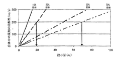
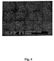
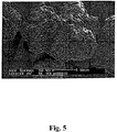


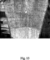


Classifications
-
- B—PERFORMING OPERATIONS; TRANSPORTING
- B05—SPRAYING OR ATOMISING IN GENERAL; APPLYING FLUENT MATERIALS TO SURFACES, IN GENERAL
- B05B—SPRAYING APPARATUS; ATOMISING APPARATUS; NOZZLES
- B05B7/00—Spraying apparatus for discharge of liquids or other fluent materials from two or more sources, e.g. of liquid and air, of powder and gas
- B05B7/02—Spray pistols; Apparatus for discharge
- B05B7/12—Spray pistols; Apparatus for discharge designed to control volume of flow, e.g. with adjustable passages
- B05B7/1209—Spray pistols; Apparatus for discharge designed to control volume of flow, e.g. with adjustable passages the controlling means for each liquid or other fluent material being manual and interdependent
-
- B—PERFORMING OPERATIONS; TRANSPORTING
- B05—SPRAYING OR ATOMISING IN GENERAL; APPLYING FLUENT MATERIALS TO SURFACES, IN GENERAL
- B05B—SPRAYING APPARATUS; ATOMISING APPARATUS; NOZZLES
- B05B15/00—Details of spraying plant or spraying apparatus not otherwise provided for; Accessories
- B05B15/50—Arrangements for cleaning; Arrangements for preventing deposits, drying-out or blockage; Arrangements for detecting improper discharge caused by the presence of foreign matter
- B05B15/55—Arrangements for cleaning; Arrangements for preventing deposits, drying-out or blockage; Arrangements for detecting improper discharge caused by the presence of foreign matter using cleaning fluids
-
- B—PERFORMING OPERATIONS; TRANSPORTING
- B05—SPRAYING OR ATOMISING IN GENERAL; APPLYING FLUENT MATERIALS TO SURFACES, IN GENERAL
- B05B—SPRAYING APPARATUS; ATOMISING APPARATUS; NOZZLES
- B05B7/00—Spraying apparatus for discharge of liquids or other fluent materials from two or more sources, e.g. of liquid and air, of powder and gas
- B05B7/02—Spray pistols; Apparatus for discharge
- B05B7/04—Spray pistols; Apparatus for discharge with arrangements for mixing liquids or other fluent materials before discharge
- B05B7/0416—Spray pistols; Apparatus for discharge with arrangements for mixing liquids or other fluent materials before discharge with arrangements for mixing one gas and one liquid
- B05B7/0441—Spray pistols; Apparatus for discharge with arrangements for mixing liquids or other fluent materials before discharge with arrangements for mixing one gas and one liquid with one inner conduit of liquid surrounded by an external conduit of gas upstream the mixing chamber
- B05B7/0475—Spray pistols; Apparatus for discharge with arrangements for mixing liquids or other fluent materials before discharge with arrangements for mixing one gas and one liquid with one inner conduit of liquid surrounded by an external conduit of gas upstream the mixing chamber with means for deflecting the peripheral gas flow towards the central liquid flow
-
- B—PERFORMING OPERATIONS; TRANSPORTING
- B05—SPRAYING OR ATOMISING IN GENERAL; APPLYING FLUENT MATERIALS TO SURFACES, IN GENERAL
- B05B—SPRAYING APPARATUS; ATOMISING APPARATUS; NOZZLES
- B05B7/00—Spraying apparatus for discharge of liquids or other fluent materials from two or more sources, e.g. of liquid and air, of powder and gas
- B05B7/02—Spray pistols; Apparatus for discharge
- B05B7/06—Spray pistols; Apparatus for discharge with at least one outlet orifice surrounding another approximately in the same plane
- B05B7/062—Spray pistols; Apparatus for discharge with at least one outlet orifice surrounding another approximately in the same plane with only one liquid outlet and at least one gas outlet
- B05B7/066—Spray pistols; Apparatus for discharge with at least one outlet orifice surrounding another approximately in the same plane with only one liquid outlet and at least one gas outlet with an inner liquid outlet surrounded by at least one annular gas outlet
Abstract
Description
本発明は、自己清掃噴霧ノズルに関し、特に、制御された凝集方法、すなわち、制御された粒子サイズの成長方法による粒状材料の製造のための装置で使用される自己清掃噴霧ノズルに関する。この装置は、特に、比較的低い水溶性を有し、及び/又は化学分解しやすく、治療的及び/又は予防的に活性な物質を含む医薬組成物の製造での使用に適している。 The present invention relates to a self-cleaning spray nozzle, and more particularly to a self-cleaning spray nozzle used in an apparatus for the production of particulate material by a controlled agglomeration method, ie a controlled particle size growth method. This device is particularly suitable for use in the manufacture of pharmaceutical compositions that have a relatively low water solubility and / or are susceptible to chemical degradation and contain therapeutically and / or prophylactically active substances.
制御された凝集方法は、本出願人に譲渡された国際特許出願番号PCT/DK02/00472に開示されている。この方法は、医薬組成物から適切に活性物質を放出し、循環系への活性物質の吸収を可能にする経口使用のための医薬組成物の製造を可能にする。 A controlled agglomeration method is disclosed in International Patent Application No. PCT / DK02 / 00472, assigned to the present applicant. This method allows the production of a pharmaceutical composition for oral use that appropriately releases the active substance from the pharmaceutical composition and allows absorption of the active substance into the circulatory system.
制御された凝集方法は、例えば高せん断又は低せん断ミキサー又は流動床内で実行される。この方法によれば、担体又は担体組成物は、ミキサー又は流動床に載せられた第二組成物上に噴霧される。一般に、担体又は担体組成物は、担体及び/又は担体組成物の融点を超える温度に加熱される。一方、第二組成物は、加熱されず、周囲温度に留まる。担体と第二組成物間の温度差により、担体は急速に凝固し、粒子サイズの成長が制御される。従って、発明者らは、このような条件を採用することにより、凝集過程を制御し、それによって、粒子サイズの成長を制御することが可能であることを見出した。 The controlled agglomeration process is carried out, for example, in a high shear or low shear mixer or fluidized bed. According to this method, the carrier or carrier composition is sprayed onto a second composition mounted on a mixer or fluidized bed. In general, the carrier or carrier composition is heated to a temperature above the melting point of the carrier and / or carrier composition. On the other hand, the second composition is not heated and remains at ambient temperature. Due to the temperature difference between the carrier and the second composition, the carrier rapidly solidifies and particle size growth is controlled. Therefore, the inventors have found that by adopting such conditions, it is possible to control the aggregation process and thereby control the growth of the particle size.
本説明を通して、「担体」という用語は、「担体組成物」の略語として用いられる。担体組成物は、1つ以上の担体を含み、1つ以上の他の成分を含んでもよい。従って、担体組成物は、親水性及び/又は疎水性担体及び/又は界面活性剤の混合物を含んでもよい。担体組成物は、1つ以上の治療的及び/又は予防的活性物質及び/又は1つ以上の医薬的に受容可能な賦形剤を含んでもよい。 Throughout this description, the term “carrier” is used as an abbreviation for “carrier composition”. The carrier composition includes one or more carriers and may include one or more other components. Thus, the carrier composition may comprise a mixture of hydrophilic and / or hydrophobic carriers and / or surfactants. The carrier composition may comprise one or more therapeutic and / or prophylactic active substances and / or one or more pharmaceutically acceptable excipients.
本発明の目的は、制御された凝集方法に従って動作する装置において、例えばせん断ミキサー又は流動床と確実に協働可能な自己清掃噴霧ノズルを提供することである。 It is an object of the present invention to provide a self-cleaning spray nozzle that can reliably cooperate with, for example, a shear mixer or a fluidized bed, in an apparatus that operates according to a controlled agglomeration method.
この噴霧ノズルでは、流動化された粒子、担体の液滴、凝固した担体粒子の何れの付着も生じないはずである。 The spray nozzle should not cause any adhesion of fluidized particles, carrier droplets, or solidified carrier particles.
本発明によれば、上述した目的及びその他の目的は、液体を供給するための中央通路を有する中央管を備え、前記通路は、液体を放出するためのオリフィスで終わり、中央管を囲む第二管を備え、それによって中央管と第二管の間に一次空気を供給するための第一通路が形成され、第二管の端に配置され、第一通路の第一放出間隙の外側の周囲を形成し、かつ第一通路を通って供給された空気を前記液体と混合して液体/基体噴霧を提供するノズル錐体と、第二管を囲む第三管を備え、それによって第二及び第三管の間に二次空気を供給するための第二通路が形成され、第三管の端に配置され、第二通路の第二放出間隙の外側の周囲を形成する外装を備える噴霧ノズルによって達成される。 In accordance with the present invention, the above and other objects comprise a central tube having a central passage for supplying liquid, said passage terminating in an orifice for discharging liquid and surrounding a central tube. A first passage for providing primary air between the central tube and the second tube is formed, and is arranged at the end of the second tube and around the outside of the first discharge gap of the first passage And a nozzle cone for mixing the liquid supplied through the first passage with the liquid to provide a liquid / substrate spray, and a third tube surrounding the second tube, whereby the second and A spray nozzle having a sheath formed with a second passage for supplying secondary air between the third tubes, disposed at an end of the third tube, and forming a periphery outside the second discharge gap of the second passage. Achieved by:
さらに、本発明による噴霧ノズルと第二組成物の流動化のための流動床を備える、制御された凝集用装置が提供される。 Furthermore, there is provided a controlled agglomeration device comprising a spray nozzle according to the present invention and a fluidized bed for fluidizing the second composition.
噴霧ノズルは、当該技術分野で周知なように、流動床の上部、流動床の側部、又は流動床の下部に取り付けることができる。 The spray nozzle can be attached to the top of the fluidized bed, the side of the fluidized bed, or the bottom of the fluidized bed, as is well known in the art.
流動床は、例えば回転(roto)流動床、ウルスター(Wurster)流動床、クーゲルコーター(Kugel coater)、ファーマスチールファスト(Pharma Steel Phast)流動床などにすることができる。 The fluidized bed can be, for example, a roto fluidized bed, a Wurster fluidized bed, a Kugel coater, a Pharma Steel Phast fluidized bed, and the like.
さらに、噴霧ノズルと第二組成物の混合のためのインテンシブミキサーを備える装置が提供される。 Furthermore, an apparatus is provided comprising an intensive mixer for mixing the spray nozzle and the second composition.
インテンシブミキサーは、高せん断ミキサー、低せん断ミキサー、水平ミキサー、垂直ミキサーなどにすることができる。 Intensive mixers can be high shear mixers, low shear mixers, horizontal mixers, vertical mixers, and the like.
さらに、噴霧乾燥機に取り付けられた、例えば、噴霧乾燥機の上部に取り付けられた、又は噴霧乾燥機の下部に取り付けられた噴霧ノズルを備える装置が提供される。 Furthermore, an apparatus is provided comprising a spray nozzle attached to the spray dryer, for example attached to the top of the spray dryer or attached to the bottom of the spray dryer.
第二組成物は、最も高くても担体の融点に対応する温度、例えば担体の融点よりも少なくても約2℃、少なくても約5℃、少なくても約10℃低い温度を有することができる。この装置では、噴霧ノズルは、液状の担体を含む第一組成物を流動床で流動化された、又はインテンシブミキサーで混合された第二組成物上に噴霧するために取り付けられる。又は、噴霧ノズルは、噴霧乾燥機において、第一組成物を噴霧乾燥するために取り付けられる。 The second composition may have a temperature corresponding at most to the melting point of the carrier, for example at least about 2 ° C., at least about 5 ° C., at least about 10 ° C. below the melting point of the carrier. it can. In this apparatus, the spray nozzle is mounted for spraying a first composition comprising a liquid carrier onto a second composition fluidized in a fluidized bed or mixed with an intensive mixer. Alternatively, the spray nozzle is attached to spray dry the first composition in a spray dryer.
第一組成物を含む温度及ぶ圧力制御されたタンクは、中央通路を有する中央管に連結されており、担体の融点を超える温度で第一組成物を供給する。さらに、温度制御された第一加圧空気供給部は、第一通路に連結され、温度制御された一次空気を噴霧ノズルに供給し、温度制御された第二加圧空気供給部は、第二通路に連結され、温度制御された二次空気を噴霧ノズルに供給する。 A temperature and pressure controlled tank containing the first composition is connected to a central tube having a central passage and supplies the first composition at a temperature above the melting point of the carrier. Furthermore, the temperature-controlled first pressurized air supply unit is connected to the first passage, supplies temperature-controlled primary air to the spray nozzle, and the temperature-controlled second pressurized air supply unit Secondary air connected to the passage and temperature controlled is supplied to the spray nozzle.
流動床、インテンシブミキサー、噴霧乾燥機と協働中に、本発明の噴霧ノズルは、第一組成物の粒子又は液滴及び第二組成物の粒子を噴霧ノズル表面に輸送する複雑な空気流中に配置される。噴霧ノズルの第二放出間隙から供給される、温度制御された二次空気は、このような粒子が噴霧ノズル表面に付着するのを抑制し、実質的に防止する。従って、噴霧ノズルは、必要とされるプロセス時間中を通して、噴霧を持続する In cooperation with a fluidized bed, intensive mixer, spray dryer, the spray nozzle of the present invention is in a complex air stream that transports particles or droplets of the first composition and particles of the second composition to the surface of the spray nozzle. Placed in. The temperature-controlled secondary air supplied from the second discharge gap of the spray nozzle suppresses and substantially prevents such particles from adhering to the spray nozzle surface. Thus, the spray nozzle will sustain the spray throughout the required process time
噴霧角度は、二次空気流を適切に調節することによって、さらに制御することができる。二次空気流は、オリフィスでの圧力を増大させ、それによって噴霧錐体の噴霧角度を減少させるために利用可能である。噴霧角度は、20°未満、好ましくは15°未満、さらに好ましくは10°未満、さらに好ましくは5°未満に設定することができる。噴霧錐体の小さな値は、噴霧された材料が容器の壁に衝突する量を最小限にし、好ましい。 The spray angle can be further controlled by appropriately adjusting the secondary air flow. The secondary air flow can be used to increase the pressure at the orifice, thereby reducing the spray angle of the spray cone. The spray angle can be set to less than 20 °, preferably less than 15 °, more preferably less than 10 °, more preferably less than 5 °. A small value for the spray cone is preferred, as it minimizes the amount of sprayed material hitting the container wall.
本噴霧ノズルは、高温溶融物をどんな環境中に噴霧するのにも非常に適している。二次空気の有益な清掃効果は、二次空気による表面加熱と組み合わさって、二次空気流自体によってもたらされていると思われる。二次空気には最適な温度範囲がある。二次空気の温度が高すぎると、粒子又は液滴は、表面に付着する傾向があり、温度が低すぎると、液滴は、表面で固化する傾向がある。 The spray nozzle is very suitable for spraying hot melts into any environment. The beneficial cleaning effect of secondary air appears to be brought about by the secondary air flow itself in combination with surface heating by the secondary air. Secondary air has an optimal temperature range. If the temperature of the secondary air is too high, the particles or droplets tend to adhere to the surface, and if the temperature is too low, the droplets tend to solidify on the surface.
最適な温度範囲は、担体の融点に関連している。 The optimum temperature range is related to the melting point of the support.
担体は、約5℃以上、例えば約10℃以上、約20℃以上又は約25℃以上の融点を有することができる。 The carrier can have a melting point of about 5 ° C or higher, such as about 10 ° C or higher, about 20 ° C or higher, or about 25 ° C or higher.
二次空気の温度は、ノズル先の表面を担体の融点範囲の下端に冷却するのに十分に低くなければならない。それよりも温度が高いと、液滴の付着により、固体の第二組成物材料が付着する結果になるであろう。それより温度が低いと、液滴は、固化し、付着蓄積のための種として働くであろう。 The temperature of the secondary air must be low enough to cool the nozzle tip surface to the lower end of the support melting point range. At higher temperatures, the deposition of the droplets will result in the deposition of the solid second composition material. Below that temperature, the droplets will solidify and serve as seeds for deposit buildup.
後述するが、第一組成物の適切な霧化には、ノズルオリフィスでの一次空気温度が担体の融点を超えるか、少なくともこれと一致することが必要である。ノズルオリフィスに対する距離で温度が急速に降下するため、一次空気は、高温であることが好ましい。温度の上限は、担体の沸点によって定められる。しかし、一次空気は、ノズルを加熱し、それによってノズル外表面を加熱する。従って、ノズルの断熱特性は、使用可能な(obtainable)一次空気の最大温度に影響を与える。 As will be described later, proper atomization of the first composition requires that the primary air temperature at the nozzle orifice exceeds or at least matches the melting point of the carrier. The primary air is preferably hot because the temperature drops rapidly with distance to the nozzle orifice. The upper temperature limit is determined by the boiling point of the support. However, the primary air heats the nozzle and thereby heats the nozzle outer surface. Thus, the thermal insulation properties of the nozzle affect the maximum temperature of the primary air that is obtainable.
ノズルオリフィス、第一及び第二放出間隙、及びその相互配置は、噴霧形成及び自己清掃が最適になるように選択される。例えば、形成された噴霧錐体の噴霧角度は、噴霧が容器の壁に衝突しないように、低い値が選択される。 The nozzle orifice, first and second discharge gaps, and their interposition are selected to optimize spray formation and self-cleaning. For example, the spray angle of the formed spray cone is selected to be low so that the spray does not hit the container wall.
本発明の好ましい実施形態では、第一放出間隙は、オリフィスとほぼ同心にすることができ、オリフィスに対して、ある距離をおいて上流に配置することができる。 In a preferred embodiment of the invention, the first discharge gap can be substantially concentric with the orifice and can be located upstream with respect to the orifice.
本発明の好ましい実施形態では、第二放出間隙は、第一放出間隙とほぼ同心にすることができ、第一放出間隙に対して、ある距離をおいて上流に配置することができる。 In a preferred embodiment of the present invention, the second discharge gap can be substantially concentric with the first discharge gap and can be located upstream with respect to the first discharge gap.
ノズルオリフィスの直径は、0.1mm〜0.3mm、好ましくは、0.5mm〜2mmにすることができる。 The diameter of the nozzle orifice can be 0.1 mm to 0.3 mm, preferably 0.5 mm to 2 mm.
第一放出間隙の幅は、3mm未満、好ましくは、0.1mm〜0.4mmにすることができる。 The width of the first discharge gap can be less than 3 mm, preferably 0.1 mm to 0.4 mm.
第二放出間隙の幅は、3mm未満、好ましくは、0.1mm〜0.4mmにすることができる。 The width of the second discharge gap can be less than 3 mm, preferably 0.1 mm to 0.4 mm.
好ましくは、噴霧ノズルは、オリフィスと中央通路の一部を含むノズル先を備える。ノズル先は、噴霧ノズルに取り外し可能に配置することができる。これによって、メンテナンス、例えば清掃及び殺菌が容易になる。 Preferably, the spray nozzle comprises a nozzle tip that includes an orifice and a portion of the central passage. The nozzle tip can be detachably disposed on the spray nozzle. This facilitates maintenance, for example cleaning and sterilization.
好ましくは、噴霧ノズルは、内側に中央通路が形成される中央管を備える。中央管は、ステンレス鋼、例えば耐酸鋼,例えばAISI 316、又は二段溶解鋼(duplex steel)、例えばSAF 2205などで形成することができる。 Preferably, the spray nozzle comprises a central tube in which a central passage is formed. The central tube can be formed of stainless steel, such as acid resistant steel, such as AISI 316, or duplex steel, such as SAF 2205.
好ましい実施形態では、中央管は、噴霧ノズル内への設置を容易にするために、柔軟なホースである。ホースは、耐熱性プラスチック、例えばPTFE,シリコーン,PVC,ポリエチレン,テフロン(登録商標),ポリエーテルエーテルケトン(PEEK)、fluorerscentなどで形成することができ、ホースの一端には、ホースをノズル先に固定するためのネジ山を設けることができる。好ましい実施形態では、中央管には、テフロン(登録商標)の裏地を設け、この裏地を、保護カバー、例えばステンレス鋼カバー又は柔軟なカバー、例えばステンレス鋼の編組カバー又はプラスチックカバーで補強する。 In a preferred embodiment, the central tube is a flexible hose to facilitate installation within the spray nozzle. The hose can be made of heat-resistant plastic such as PTFE, silicone, PVC, polyethylene, Teflon (registered trademark), polyetheretherketone (PEEK), fluorerscent, etc. Screw threads can be provided for fixing. In a preferred embodiment, the central tube is provided with a Teflon lining, which is reinforced with a protective cover, such as a stainless steel cover or a flexible cover, such as a stainless steel braided cover or a plastic cover.
好ましくは、中央管は、噴霧ノズルに取り外し可能に配置され、使用後に廃棄することができる。これによって、噴霧ノズルの清掃及び殺菌が容易になる。好ましくは、中央管及びノズル先は、取り外し可能に噴霧ノズル内に配置されるユニットを形成し、使用後に廃棄することができる。これによって、噴霧ノズルの清掃及び殺菌が容易になる。これによって、バッチ生産の合間の面倒で時間のかかる中央管及びノズル先の清掃は、完全になくなる。 Preferably, the central tube is removably disposed in the spray nozzle and can be discarded after use. This facilitates cleaning and sterilization of the spray nozzle. Preferably, the central tube and nozzle tip form a unit that is removably disposed within the spray nozzle and can be discarded after use. This facilitates cleaning and sterilization of the spray nozzle. This eliminates the tedious and time-consuming cleaning of the central tube and nozzle tip between batch productions.
さらに、噴霧ノズルは、中央管を囲む第二管を備えることができる。第一通路は、中央管と第二管の間に形成される。好ましくは、第二管は、ステンレス鋼、例えばAISI 316又はSAF 2205で形成される。 Furthermore, the spray nozzle can comprise a second tube surrounding the central tube. The first passage is formed between the central tube and the second tube. Preferably, the second tube is formed of stainless steel, such as AISI 316 or SAF 2205.
噴霧ノズルは、第二管を囲む第三管を備えることができる。第二通路は、第二管と第三管の間に形成される。好ましくは、第三管は、ステンレス鋼、例えばAISI 316又はSAF 2205で形成される。 The spray nozzle can comprise a third tube surrounding the second tube. The second passage is formed between the second pipe and the third pipe. Preferably, the third tube is formed of stainless steel, such as AISI 316 or SAF 2205.
第二管の端に配置され、かつ第一放出間隙の周囲を形成するノズル錐体を設けることができる。好ましくは、ノズル錐体は、プラスチック、例えばポリカーボネート又はナイロンなどで形成される。さらに好ましくは、ノズル錐体は、ステンレス鋼、例えばAISI 316又はSAF 2205で形成される。ノズル錐体は、最適な噴霧形成のための第一放出間隙のサイズ調節のために、第二管の端に調節可能に配置することができる。さらに、ノズル錐体は、噴霧ノズルのメンテナンスと修理を容易にするために、第二管に取り外し可能に取り付けることができる。例えば、ノズル錐体は、第二管に設けられる対応するネジ山に係合するネジ山を備えることができる。ノズルオリフィスに対する第一放出間隙の位置は、第二管に対するノズル錐体の回転によって調節することができる。ネジ山のピッチが、回転角の関数として位置調節を決定する。ノズル錐体がオリフィスに向かって先細りであるとき、第一放出間隙の位置変化は、第一放出間隙の幅も変化させる。第二管に目盛りを設け、ノズル錐体にマークを設けることもできるし、その逆も可能である。これにより、ノズル錐体の対応する回転により目盛りに対してマーカーを適切に配置することによって、所望の第一放出間隙幅にセットすることができる。 A nozzle cone may be provided that is disposed at the end of the second tube and that forms the periphery of the first discharge gap. Preferably, the nozzle cone is formed of plastic, such as polycarbonate or nylon. More preferably, the nozzle cone is formed of stainless steel, such as AISI 316 or SAF 2205. The nozzle cone can be adjustably disposed at the end of the second tube for size adjustment of the first discharge gap for optimal spray formation. Further, the nozzle cone can be removably attached to the second tube to facilitate maintenance and repair of the spray nozzle. For example, the nozzle cone can include threads that engage corresponding threads provided on the second tube. The position of the first discharge gap relative to the nozzle orifice can be adjusted by rotation of the nozzle cone relative to the second tube. The pitch of the thread determines the position adjustment as a function of the rotation angle. When the nozzle cone tapers toward the orifice, the change in position of the first discharge gap also changes the width of the first discharge gap. A scale can be provided on the second tube, and a mark can be provided on the nozzle cone, and vice versa. Thereby, it is possible to set the desired first discharge gap width by appropriately arranging the marker with respect to the scale by the corresponding rotation of the nozzle cone.
第三管の端に配置され、かつ第二放出間隙の周囲を形成する外装を設けることができる。さらに、外装は、最適な自己清掃性能のための第二放出間隙のサイズ調節のために、第三管の端に調節可能に配置することができる。外装は、噴霧ノズルのメンテナンスと修理を容易にするために、第三管に取り外し可能に取り付けることができる。 A sheath can be provided that is disposed at the end of the third tube and that forms the periphery of the second discharge gap. Furthermore, the sheath can be adjustably placed at the end of the third tube for size adjustment of the second discharge gap for optimal self-cleaning performance. The sheath can be removably attached to the third tube to facilitate maintenance and repair of the spray nozzle.
例えば、ノズル外装は、第三管に設けられる対応するネジ山に係合するネジ山を備えることができる。第一放出間隙に対する第二放出間隙の位置は、第三管に対するノズル外装の回転によって調節することができる。ネジ山のピッチが、回転角の関数として位置調節を決定する。ノズル錐体が第一放出間隙に向かって先細りであるとき、第二放出間隙の位置変化は、第二放出間隙の幅も変化させる。第三管に目盛りを設け、ノズル外装にマークを設けることもできるし、その逆も可能である。これにより、ノズル外装の対応する回転により目盛りに対してマーカーを適切に配置することによって、所望の第二放出間隙幅にセットすることができる。 For example, the nozzle sheath can include threads that engage corresponding threads provided on the third tube. The position of the second discharge gap relative to the first discharge gap can be adjusted by rotation of the nozzle sheath relative to the third tube. The pitch of the thread determines the position adjustment as a function of the rotation angle. When the nozzle cone is tapered toward the first discharge gap, the change in position of the second discharge gap also changes the width of the second discharge gap. A scale can be provided on the third tube, and a mark can be provided on the nozzle exterior, and vice versa. Thereby, it is possible to set the desired second discharge gap width by appropriately arranging the marker with respect to the scale by the corresponding rotation of the nozzle exterior.
好ましくは、外装は、第二放出間隙に向かって先細りである。これによって、噴霧の間、外装には水平面が実質的に存在せず、噴霧ノズルへの物質の付着がさらに少なくなる。 Preferably, the sheath is tapered towards the second discharge gap. Thus, during spraying, there is substantially no horizontal surface on the exterior, and material adhesion to the spray nozzle is further reduced.
外装は、ステンレス鋼、例えばAISI 316又はSAF 2205で形成することができる。好ましくは、外装は、強化プラスチック材料、例えばPeekなどで形成される。これによって、熱に安定でべたつきがなく、湿気を吸収しない外装が得られる。 The sheath can be made of stainless steel, such as AISI 316 or SAF 2205. Preferably, the sheath is formed of a reinforced plastic material such as Peek. As a result, it is possible to obtain an exterior that is stable to heat, does not stick, and does not absorb moisture.
好ましくは、例えばノズル錐体と第二管のようにネジ山係合で互いに移動可能に取り付けられた噴霧ノズルの異なる部品は、互いに対する部品の移動による材料の穴の拡大を避けるために、異なるタイプのステンレス鋼、例えばそれぞれAISI 316及びSAF 2205で形成する。 Preferably, different parts of the spray nozzle which are mounted movably relative to each other with thread engagement, for example the nozzle cone and the second tube, are different in order to avoid expansion of the material hole due to movement of the parts relative to each other Formed with a type of stainless steel, eg AISI 316 and SAF 2205 respectively.
噴霧ノズルにはテフロン(登録商標) コーティングの表面を設けることができる。例えば、外装をテフロン(登録商標)コーティングし、ノズル錐体をテフロン(登録商標) コーティングし、それぞれの表面への粒子の付着をさらに抑制することができる。 The spray nozzle can be provided with a Teflon-coated surface. For example, the exterior can be coated with Teflon (registered trademark), and the nozzle cone can be coated with Teflon (registered trademark) to further suppress the adhesion of particles to each surface.
噴霧ノズルは、角度をつけることができ、又は曲げることができる。この場合、噴霧ノズルは、第一軸に沿って延びる第一部品と、第一軸と角度αをなす第二軸に沿って延びる第二部品とを備える。角度αは、90°にほぼ等しいか、それより小さく、例えば60°にほぼ等しくすることができる。これによって、せん断ミキサー又は流動床などにおいて噴霧ノズルの配置が容易になる。 The spray nozzle can be angled or bent. In this case, the spray nozzle includes a first part extending along the first axis and a second part extending along the second axis that forms an angle α with the first axis. The angle α can be approximately equal to 90 ° or smaller, for example approximately equal to 60 °. This facilitates the placement of the spray nozzles in a shear mixer or fluidized bed.
噴霧錐体の噴霧角度をさらに制御するために、一次空気の通路用アパーチャー又はチャネルを備える部材をノズル錐体に設けることができる。アパーチャー又はチャネルの縦軸は、第二管の縦軸とある角度をなすことができる。これによって、一次空気流に渦流が誘起される。流れの渦巻き運動は、渦巻きと比較的圧力の低い領域を形成し、それによって、噴霧角度が増大する。 In order to further control the spray angle of the spray cone, the nozzle cone can be provided with a member comprising a primary air passage aperture or channel. The longitudinal axis of the aperture or channel can form an angle with the longitudinal axis of the second tube. This induces a vortex in the primary air flow. The swirling motion of the flow forms a relatively low pressure area with the swirl, thereby increasing the spray angle.
本装置は、多くの量の担体を固体材料に取り込むことを可能にする。この担体は、例えばその溶解特性により、比較的低い水溶性を有し、治療的及び/又は予防的に活性な物質を多く取り込むことができるタイプである。担体は、通常、固体又は半固体であり、通常、粘着性、油性又は蝋質の特性を有している。しかし、担体は、室温や5℃以下の温度で流動性を有するものであってもよい。このような場合、本装置は、第二組成物を冷却して、動かされると思われる。新規な制御された凝集用装置を用いることによって、多くの量の担体を含む粒状材料を製造することができ、その結果得られる粒状材料は、固体の粒状粉体となる。新規な装置によって得られる粒状材料は、流動性、充填密度、密集性に関して優れた特性を有しており、例えば錠剤の製造での使用に適している。粒状材料は実質的に粘着性の性質を持った担体を多く含むことがあるが、製造される粒状材料は、錠剤の製造の際の錠剤パンチ及び/又は鋳型への付着は、あったとしても最小限である。 The device allows a large amount of carrier to be incorporated into the solid material. This carrier is of the type that has a relatively low water solubility, for example due to its solubility characteristics, and can incorporate a large amount of therapeutically and / or prophylactically active substances. The carrier is usually a solid or semi-solid and usually has sticky, oily or waxy properties. However, the carrier may have fluidity at room temperature or a temperature of 5 ° C. or lower. In such a case, the device would be moved with the second composition cooled. By using a new controlled agglomeration device, it is possible to produce a granular material containing a large amount of carrier, and the resulting granular material is a solid granular powder. The granular material obtained by the new apparatus has excellent properties with respect to fluidity, packing density and compactness and is suitable for use in the production of tablets, for example. The granular material may contain a large amount of substantially sticky carrier, but the produced granular material may be attached to the tablet punch and / or mold during the manufacture of the tablet, if any. Minimal.
担体
担体は、例えば低くても約30℃、低くても約35℃又は低くても約40℃のような低くても約25℃の融点を有するタイプである。実用的な理由から、融点は高すぎず、したがって、担体は、通常、例えば高くても約250℃、高くても約200℃、高くても約150℃又は高くても約100℃のような高くても約300℃の融点を有する。融点がより高いと、溶融した担体を噴霧剤の形態で提供することが必要な噴霧装置に担体を送達する間、充分に高い温度を保つことを確実にすることが非常に困難になる。さらに、例えば治療的及び/又は予防的活性物質が担体に含まれる場合、比較的高い温度は、該物質の例えば酸化又は他の種類の分解を促進するであろう。
Carrier The carrier is of the type having a melting point of at most about 25 ° C., such as at least about 30 ° C., at least about 35 ° C. or at least about 40 ° C. For practical reasons, the melting point is not too high, so the support is usually such as at most about 250 ° C., at most about 200 ° C., at most about 150 ° C. or at most about 100 ° C. At most, it has a melting point of about 300 ° C. The higher melting point makes it very difficult to ensure that a sufficiently high temperature is maintained during delivery of the carrier to a spray device that requires providing the molten carrier in the form of a propellant. Furthermore, if a therapeutic and / or prophylactically active substance is included in the carrier, for example, a relatively high temperature will promote, for example, oxidation or other types of degradation of the substance.
本発明との関係において、融点はDSC(示差走査熱量測定)により測定される。融点は、DSCカーブの直線的な増加が温度軸と交わる温度として測定される(更なる詳細は図6を参照)。 In the context of the present invention, the melting point is measured by DSC (differential scanning calorimetry). The melting point is measured as the temperature at which the linear increase in the DSC curve intersects the temperature axis (see Figure 6 for further details).
好適な担体は、いわゆる溶融結合剤もしくは固体溶剤(固体投与形態の形態にある)のような、又は局所使用の薬剤における共溶剤もしくは処方成分のような薬剤の製造において用いられる一般的な物質である。 Suitable carriers are common substances used in the manufacture of drugs such as so-called melt binders or solid solvents (in the form of solid dosage forms) or as co-solvents or formulation ingredients in drugs for topical use. is there.
担体は、親水性、疎水性であってもよく、及び/又は表面活性特性を有していてもよい。一般的に、親水性及び/又は疎水性の担体は、比較的低い水溶解性を有する治療的及び/又は予防的活性物質を含む医薬組成物の製造における使用において、及び/又は医薬組成物からの活性物質の放出を即時もしくは非修飾となるように設計するときに好適である。一方、疎水性の担体は、修飾放出(modified release)医薬組成物の製造において通常用いられる。上述の考察は、一般的な原則を説明するのに単純化されているが、他の担体の組み合わせ、及び他の目的が適切な場合が多くあり、したがって、上記の例示は本発明を限定するものではない。 The carrier may be hydrophilic, hydrophobic and / or have surface active properties. In general, hydrophilic and / or hydrophobic carriers are used in the manufacture of pharmaceutical compositions and / or from pharmaceutical compositions comprising therapeutic and / or prophylactically active substances with relatively low water solubility. This is suitable when the release of the active substance is designed to be immediate or unmodified. On the other hand, hydrophobic carriers are commonly used in the manufacture of modified release pharmaceutical compositions. Although the above discussion has been simplified to illustrate the general principles, other carrier combinations and other purposes are often appropriate, and thus the above illustrations limit the invention It is not a thing.
好適な担体の例は、親水性担体、疎水性担体、界面活性剤又はこれらの混合物である。 Examples of suitable carriers are hydrophilic carriers, hydrophobic carriers, surfactants or mixtures thereof.
典型的には、好適な親水性担体は:例えばポリエチレングリコール、ポリプロピレングリコールのようなポリエーテルグリコール;ポリオキシエチレン;ポリオキシプロピレン;ポロキサマー及びこれらの混合物からなる群より選択されるか、又は:キシリトール、ソルビトール、酒石酸ナトリウムカリウム、スクローストリベヘネート、グルコース、ラムノース、ラクチトール、ベヘン酸、ヒドロキノンモノメチルエーテル、酢酸ナトリウム、フマル酸エチル、ミリスチン酸、クエン酸、Gelucire 50/13、例えばGelucire 44/14などのほかのGelucireタイプ、Gelucire 50/10、Gelucire 62/05、Sucro-ester 7、Sucro-ester 11、Sucro-ester 15、マルトース、マンニトール及びこれらの混合物からなる群より選択することができる。
Typically, suitable hydrophilic carriers are selected from the group consisting of: polyether glycols such as polyethylene glycol, polypropylene glycol; polyoxyethylene; polyoxypropylene; poloxamers and mixtures thereof, or: xylitol Sorbitol, sodium potassium tartrate, sucrose tribehenate, glucose, rhamnose, lactitol, behenic acid, hydroquinone monomethyl ether, sodium acetate, ethyl fumarate, myristic acid, citric acid,
本発明の装置において用いる疎水性担体は:直鎖状飽和炭化水素、ソルビタンエステル、パラフィン;例えばカカオバター、牛脂、ラード、ポリエーテルグリコールエステルのような油脂;例えばステアリン酸、ミリスチン酸、パルミチン酸のような高級脂肪酸、例えばセタノール、ステアリルアルコールなどの高級アルコール、例えばグリセリルモノステアレート、硬化獣脂のような低融点ワックス、ミリスチルアルコール、ステアリルアルコール、置換及び/又は非置換のモノグリセリド、置換及び/又は非置換のジグリセリド、置換及び/又は非置換のトリグリセリド、蜜ろう、さらし蜜ろう、カルナウバワックス、カストールワックス、木ろう、アセチレートモノグリセリド;NVPポリマー、PVPポリマー、アクリルポリマー、又はこれらの混合物からなる群より選択することができる。 Hydrophobic carriers used in the apparatus of the present invention are: linear saturated hydrocarbons, sorbitan esters, paraffins; fats and oils such as cocoa butter, beef tallow, lard, polyether glycol esters; for example stearic acid, myristic acid, palmitic acid Higher fatty acids such as higher alcohols such as cetanol, stearyl alcohol, such as glyceryl monostearate, low melting waxes such as hardened tallow, myristyl alcohol, stearyl alcohol, substituted and / or unsubstituted monoglycerides, substituted and / or non Substituted diglycerides, substituted and / or unsubstituted triglycerides, beeswax, bleached beeswax, carnauba wax, castor wax, wood wax, acetylate monoglyceride; NVP polymer, PVP polymer, acrylic polymer, or a mixture thereof It can be selected from the group consisting of compounds.
興味のある実施形態では、担体は、例えば約800〜約35,000、約1,000〜約35,000のような約400〜約35,000の範囲の平均分子量を有するポリエチレングリコール、例えばポリエチレングリコール1,000、ポリエチレングリコール2,000、ポリエチレングリコール3,000、ポリエチレングリコール4,000、ポリエチレングリコール5,000、ポリエチレングリコール6,000、ポリエチレングリコール7,000、ポリエチレングリコール8,000、ポリエチレングリコール9,000、ポリエチレングリコール10,000、ポリエチレングリコール15,000、ポリエチレングリコール20,000、又はポリエチレングリコール35,000である。ある状況では、ポリエチレングリコールは約35,000〜約100,000の分子量のものを用いてもよい。 In an embodiment of interest, the carrier is a polyethylene glycol having an average molecular weight in the range of about 400 to about 35,000, such as about 800 to about 35,000, about 1,000 to about 35,000, such as polyethylene glycol 1,000, polyethylene glycol 2,000, polyethylene. Glycol 3,000, polyethylene glycol 4,000, polyethylene glycol 5,000, polyethylene glycol 6,000, polyethylene glycol 7,000, polyethylene glycol 8,000, polyethylene glycol 9,000, polyethylene glycol 10,000, polyethylene glycol 15,000, polyethylene glycol 20,000, or polyethylene glycol 35,000. In certain situations, polyethylene glycols having a molecular weight of about 35,000 to about 100,000 may be used.
他の興味のある実施形態においては、担体は、例えば約2,000〜約100,000、約5,000〜約75,000、約10,000〜約60,000、約15,000〜約50,000、約20,000〜約40,000のような約2,000〜約7,000,000、例えば約100,000〜約1,000,000、約100,000〜約600,000、約100,000〜約400,000、又は約100,000〜約300,000のような約100,000〜約7,000,000の分子量を有するポリエチレンオキサイドである。 In other interesting embodiments, the carrier can be from about 2,000 to about 100,000, such as from about 2,000 to about 100,000, from about 5,000 to about 75,000, from about 10,000 to about 60,000, from about 15,000 to about 50,000, from about 20,000 to about 40,000. Polyethylene oxide having a molecular weight of from about 100,000 to about 7,000,000, such as from about 100,000 to about 1,000,000, from about 100,000 to about 600,000, from about 100,000 to about 400,000, or from about 100,000 to about 300,000.
他の実施形態においては、担体は、例えばポロキサマー188、ポロキサマー237、ポロキサマー338もしくはポロキサマー407のようなポロキサマー、又はPluronic(登録商標)及び/又はTetronic(登録商標)シリーズのようなエチレンオキサイドならびにプロピレンオキサイドのその他のブロックコポリマーである。Pluronic(登録商標)シリーズの好適なブロックコポリマーは、例えば約4,000〜約20,000のような約3,000以上の分子量、及び/又は例えば約250〜約3,000 cpsのような約200〜約4,000 cpsの粘度(Brookfield)を有するポリマーを含む。好適な例は、Pluronic(登録商標)F38、P65、P68LF、P75、F77、P84、P85、F87、F88、F98、P103、P104、P105、F108、P123、F123、F127、10R8、17R8、25R5、25R8などを含む。Tetronic(登録商標)シリーズの好適なブロックコポリマーは、例えば約9,000〜約35,000のような約8,000以上の分子量、及び/又は例えば約600〜約40,000 cpsのような約500〜約45,000 cpsの粘度(Brookfield)を有するポリマーを含む。上記の粘度は、室温でペーストである物質については60℃で、室温で固体である物質については77℃で測定する。 In other embodiments, the carrier is, for example, a poloxamer such as poloxamer 188, poloxamer 237, poloxamer 338 or poloxamer 407, or ethylene oxide and propylene oxide such as Pluronic® and / or Tetronic® series. Other block copolymers. Pluronic® series of suitable block copolymers have a molecular weight of, for example, about 3,000 or more, such as from about 4,000 to about 20,000, and / or a viscosity of about 200 to about 4,000 cps, such as from about 250 to about 3,000 cps ( Brookfield). Suitable examples are Pluronic® F38, P65, P68LF, P75, F77, P84, P85, F87, F88, F98, P103, P104, P105, F108, P123, F123, F127, 10R8, 17R8, 25R5, Including 25R8. Suitable block copolymers of the Tetronic® series include molecular weights of about 8,000 or more, such as from about 9,000 to about 35,000, and / or viscosities from about 500 to about 45,000 cps, such as from about 600 to about 40,000 cps ( Brookfield). The viscosity is measured at 60 ° C. for substances that are pastes at room temperature and 77 ° C. for substances that are solids at room temperature.
担体は、例えばソルビタンジ−イソステアレート、ソルビタンジオレエート、ソルビタンモノラウレート、ソルビタンモノイソステアレート、ソルビタンモノオレエート、ソルビタンモノパルミテート、ソルビタンモノステアレート、ソルビタンセスキ−イソステアレート、ソルビタンセスキオレエート、ソルビタンセスキステアレート、ソルビタントリ−イソステアレート、ソルビタントリオレエート、ソルビタントリステアレート、又はこれらの混合物のようなソルビタンエステルであってもよい。 Examples of the carrier include sorbitan di-isostearate, sorbitan dioleate, sorbitan monolaurate, sorbitan monoisostearate, sorbitan monooleate, sorbitan monopalmitate, sorbitan monostearate, sorbitan sesqui-isostearate, sorbitan It may be a sorbitan ester such as sesquioleate, sorbitan sesquistearate, sorbitan tri-isostearate, sorbitan trioleate, sorbitan tristearate, or mixtures thereof.
担体組成物は、当然、例えば親水性及び/又は疎水性の担体の混合物のような異なる担体の混合物を含むことができる。 The carrier composition can of course comprise a mixture of different carriers, for example a mixture of hydrophilic and / or hydrophobic carriers.
他の興味のある実施形態においては、担体は、界面活性剤又は界面活性特性を有する物質である。このような物質は、例えば溶けにくい活性物質の湿潤に関与し、したがって活性物質の溶解特性の向上に貢献すると考えられる。 In other interesting embodiments, the carrier is a surfactant or a substance having surface active properties. Such a substance is considered to be involved in, for example, wetting of an active substance that is difficult to dissolve, and thus contributes to an improvement in the solubility characteristics of the active substance.
界面活性剤の例を次に示す。担体としての使用に適するためには、本明細書で論じる融点及び/又は粘度に関する基準を満たさなければならない。しかしながら、界面活性剤は医薬的に許容される賦形剤として担体組成物に添加することもできるので、以下のリストは一般的な界面活性剤を包含している。 Examples of surfactants are shown below. In order to be suitable for use as a carrier, the melting point and / or viscosity criteria discussed herein must be met. However, the following list includes common surfactants since surfactants can also be added to the carrier composition as pharmaceutically acceptable excipients.
担体組成物としての使用(及び、上述したように、担体自体としての使用)に好適な賦形剤は、例えばLipocine, Incの名義でWO 00/50007の中に記載されたもののような疎水性及び/又は親水性の界面活性剤などの界面活性剤である。好適な界面活性剤の例は、 Excipients suitable for use as a carrier composition (and as described above for use as the carrier itself) are hydrophobic, such as those described in WO 00/50007 in the name of Lipocine, Inc. And / or a surfactant such as a hydrophilic surfactant. Examples of suitable surfactants are:
i) 例えばラウリン酸、オレイン酸、ステアリン酸、ミリスチン酸、リシノール酸とポリエチレングリコールとのモノ−又はジエステルのような、ポリエチレングリコールの脂肪酸モノ−もしくはジエステル、又はこれらの混合物などのポリエトキシル化脂肪酸であって、ポリエチレングリコールは、PEG 4、PEG 5、PEG 6、PEG 7、PEG 8、PEG 9、PEG 10、PEG 12、PEG 15、PEG 20、PEG 25、PEG 30、PEG 32、PEG 40、PEG 45、PEG 50、PEG 55、PEG 100、PEG 200、PEG 400、PEG 600、PEG 800、PEG 1000、PEG 2000、PEG 3000、PEG 4000、PEG 5000、PEG 6000、PEG 7000、PEG 8000、PEG 9000、PEG 1000、PEG 10,000、PEG 15,000、PEG 20,000、PEG 35,000から選択することができる、
i) Polyethoxylated fatty acids such as fatty acid mono- or diesters of polyethylene glycol, such as lauric acid, oleic acid, stearic acid, myristic acid, mono- or diesters of ricinoleic acid and polyethylene glycol, or mixtures thereof. Polyethylene glycol is PEG 4, PEG 5, PEG 6, PEG 7, PEG 8, PEG 9,
ii) ポリエチレングリコールグリセロール脂肪酸エステル、すなわち上述したようなエステルであるが、各脂肪酸のグリセリルエステルの形態にあるもの; ii) polyethylene glycol glycerol fatty acid esters, ie esters as described above, but in the form of glyceryl esters of each fatty acid;
iii) 例えば硬化ひまし油、アーモンド油、パーム核油、ひまし油、杏仁油、オリーブ油、ピーナッツ油、硬化パーム核油などのような植物油とのグリセロール、プロピレングリコール、エチレングリコール、PEG、又はソルビトールエステル、 iii) glycerol, propylene glycol, ethylene glycol, PEG or sorbitol esters with vegetable oils such as hydrogenated castor oil, almond oil, palm kernel oil, castor oil, apricot oil, olive oil, peanut oil, hydrogenated palm kernel oil, etc.
iv) 例えばポリグリセロールステアレート、ポリグリセロールオレエート、ポリグリセロールリシノレート、ポリグリセロールリノレートのようなポリグリセリン化脂肪酸、 iv) polyglycerinated fatty acids such as polyglycerol stearate, polyglycerol oleate, polyglycerol ricinoleate, polyglycerol linoleate,
v) 例えばプロピレングリコールモノラウレート、プロピレングリコールリシノレートなどのようなプロピレングリコール脂肪酸エステル、 v) propylene glycol fatty acid esters such as propylene glycol monolaurate, propylene glycol ricinolate, etc.
vi) 例えばグリセリルモノオレエート、グリセリルジオレエート、グリセリルモノ−及び/又はジオレエート、グリセリルカプリレート、グリセリルカプレートなどのようなモノ−及びジグリセリド; vi) mono- and diglycerides such as glyceryl monooleate, glyceryl dioleate, glyceryl mono- and / or dioleate, glyceryl caprylate, glyceryl caprate, etc .;
vii) ステロール及びステロール誘導体; vii) sterols and sterol derivatives;
viii) 上記の種々の分子量を有するPEGのエステル、及び種々のTween(登録商標)シリーズのようなポリエチレングリコールソルビタン脂肪酸エステル(PEG-ソルビタン脂肪酸エステル); viii) PEG esters having various molecular weights as described above, and polyethylene glycol sorbitan fatty acid esters (PEG-sorbitan fatty acid esters) such as various Tween® series;
ix) 例えばPEGオレイルエーテル及びPEGラウリルエーテルのようなポリエチレングリコールアルキルエーテル; ix) polyethylene glycol alkyl ethers such as PEG oleyl ether and PEG lauryl ether;
x) 例えばスクロースモノパルミテート及びスクロースモノラウレートのような糖エステル; x) sugar esters such as sucrose monopalmitate and sucrose monolaurate;
xi) 例えばTriton (登録商標) X又はNシリーズなどのポリエチレングリコールアルキルフェノール; xi) Polyethylene glycol alkylphenols such as Triton® X or N series;
xii) 例えばPluronic (登録商標)シリーズ、Synperonic (登録商標)シリーズ、Emkalyx (登録商標)、Lutrol (登録商標)、 Supronic (登録商標)などのようなポリオキシエチレン−ポリオキシプロピレンブロックコポリマー。これらのポリマーの一般名は、「ポロキサマー」であり、本発明との関係における適切な例は、ポロキサマー105、108、122、123、124、181、182、183、184、185、188、212、215、217、231、234、235、237、238、282、284、288、331、333、334、335、338、401、402、403及び407である; xii) Polyoxyethylene-polyoxypropylene block copolymers such as Pluronic® series, Synperonic® series, Emkalyx®, Lutrol®, Supronic®, etc. The generic name for these polymers is “poloxamer” and suitable examples in the context of the present invention are poloxamers 105, 108, 122, 123, 124, 181, 182, 183, 184, 185, 188, 212, 215, 217, 231, 234, 235, 237, 238, 282, 284, 288, 331, 333, 334, 335, 338, 401, 402, 403 and 407;
xiii) 例えばソルビタンモノラウレート、ソルビタンモノパルミテート、ソルビタンモノオレエート、ソルビタンモノステアレートなどのようなSpan (登録商標)シリーズ又はAriacel (登録商標)シリーズのようなソルビタン脂肪酸エステル; xiii) Sorbitan fatty acid esters such as Span® series or Ariacel® series such as sorbitan monolaurate, sorbitan monopalmitate, sorbitan monooleate, sorbitan monostearate, etc .;
xiv) 例えばオレエート、イソプロピルミリステート、イソプロピルパルミテートなどのような低級アルコール脂肪酸エステル; xiv) lower alcohol fatty acid esters such as oleate, isopropyl myristate, isopropyl palmitate, etc .;
xv) 例えば脂肪酸塩、胆汁酸塩、リン脂質、リン酸エステル、カルボキシレート、サルフェート及びスルホネートなどのような、カチオン、アニオン及び両性界面活性剤を含むイオン性界面活性剤。 xv) ionic surfactants including cationic, anionic and amphoteric surfactants such as fatty acid salts, bile salts, phospholipids, phosphate esters, carboxylates, sulfates and sulfonates.
担体組成物中に界面活性剤もしくは界面活性剤の混合物が存在する場合、界面活性剤の濃度は、通常、例えば約0.1〜約20% w/w、約0.1〜約15% w/w、約0.5〜約10% w/wのような約0.1〜75% w/wの範囲であるか、又は代わりに、担体もしくは担体組成物の部分として適用できる場合に、例えば約25〜約70% w/w、約30〜約60% w/wのような約20〜約75% w/wである。 When a surfactant or mixture of surfactants is present in the carrier composition, the concentration of the surfactant is typically about 0.1 to about 20% w / w, about 0.1 to about 15% w / w, about In the range of about 0.1 to 75% w / w, such as 0.5 to about 10% w / w, or alternatively when applicable as part of a carrier or carrier composition, for example about 25 to about 70% w / w, about 20 to about 75% w / w, such as about 30 to about 60% w / w.
担体組成物中の他の好適な賦形剤は、例えばプロピレングリコール、Gelucire 44/14を含むポリグリコール化グリセリド、カカオ脂、カルナウバワックス、例えばアーモンド油、ココナツ油、コーン油、綿実油、ごま油、大豆油、オリーブ油、ひまし油、パーム核油、ピーナツ油、なたね油、グレープシード油などのような植物油、例えば硬化ピーナツ油、硬化パーム核油、硬化綿実油、硬化大豆油、硬化ひまし油、硬化ココナツ油のような硬化植物油を含む植物起源の複合脂肪性物質;蜜ろう、ラノリン、セチル、ステアリル、ラウリック、ミリスチック、パルミチック、ステアリック脂肪性アルコールを含む脂肪性アルコールを含む動物起源の天然脂肪性物質;グリセロールステアレート、グリコールステアレート、エチルオレエート、イソプロピルミリステートを含むエステル;Miglycol 810/812を含む液体エステル交換化半合成グリセリド;ステアラミドエタノール、ココナツ脂肪酸のジエタノールアミドなどを含むアミド又は脂肪酸アルコールアミドのような、溶剤又は半固体の賦形剤である。 Other suitable excipients in the carrier composition include, for example, propylene glycol, polyglycolized glycerides including Gelucire 44/14, cocoa butter, carnauba wax such as almond oil, coconut oil, corn oil, cottonseed oil, sesame oil, Vegetable oils such as soybean oil, olive oil, castor oil, palm kernel oil, peanut oil, rapeseed oil, grape seed oil etc., such as hydrogenated peanut oil, hydrogenated palm kernel oil, hydrogenated cottonseed oil, hydrogenated soybean oil, hydrogenated castor oil, hydrogenated coconut oil Natural fatty substances of animal origin including fatty alcohols including fatty alcohols including beeswax, lanolin, cetyl, stearyl, lauric, myristic, palmitic, stearic fatty alcohols; glycerol stears Rate, glycol stearate, ethyl oleate, isopropyl Esters containing pyrmyristate; Liquid transesterified semi-synthetic glycerides containing Miglycol 810/812; Solvents or semi-solid excipients such as stearamide ethanol, amides containing coconut fatty acid diethanolamide, or fatty acid alcohol amides It is.
担体組成物中の他の添加剤は、例えばアスコルビン酸、アスコルビルパルミテート、ブチル化ヒドロキシアニソール、ブチル化ヒドロキシトルエン、次亜リン酸、モノチオグリセロール、メタ重亜硫酸カリウム、没食子酸プロピル、ソディウムホルムアルデヒドスルホキシレート、メタ重亜硫酸ナトリウム、チオ硫酸ナトリウム、二酸化硫黄、トコフェロール、酢酸トコフェロール、トコフェロールへミスクシネート、TPGS又はその他のトコフェロール誘導体などのような抗酸化剤であってもよい。担体組成物は、例えば安定化剤を含んでいてもよい。担体組成物中の抗酸化剤及び/又は安定化剤の濃度は、通常、約0.1% w/w〜約5% w/wである。 Other additives in the carrier composition include, for example, ascorbic acid, ascorbyl palmitate, butylated hydroxyanisole, butylated hydroxytoluene, hypophosphorous acid, monothioglycerol, potassium metabisulfite, propyl gallate, sodium formaldehyde sulfone It may be an antioxidant such as xylate, sodium metabisulfite, sodium thiosulfate, sulfur dioxide, tocopherol, tocopherol acetate, tocopherol hemisuccinate, TPGS or other tocopherol derivatives. The carrier composition may contain, for example, a stabilizer. The concentration of antioxidant and / or stabilizer in the carrier composition is typically about 0.1% w / w to about 5% w / w.
担体組成物を用いる場合、上述した融点に関する要件は、通常、担体組成物にも適用され、特に担体組成物中に少量の水が含まれる場合である。しかしながら、担体組成物が加熱されると、担体組成物は2以上の相の形態になる(例えば明らかな2つの液相、又は例えばそこに分散した活性物質を含む液相)。このような場合、融点は本来の融点ではなく、単に担体組成物が噴霧装置において用いるのに適した液体形状になる加熱点である。このような加熱点は、しばしば実用的な目的のために、担体自体の融点に相当する。 When using a carrier composition, the above-mentioned requirements regarding the melting point usually apply to the carrier composition, particularly when a small amount of water is contained in the carrier composition. However, when the carrier composition is heated, the carrier composition is in the form of two or more phases (eg, two distinct liquid phases, or a liquid phase containing, for example, the active substance dispersed therein). In such cases, the melting point is not the original melting point, but simply the heating point at which the carrier composition is in a liquid form suitable for use in a spray device. Such a heating point often corresponds to the melting point of the support itself for practical purposes.
担体組成物中の担体の全濃度は、通常、例えば約10〜99.5% w/w、約15〜99% w/w、約15〜98% w/w、約15〜97% w/w、約20〜95% w/w、例えば少なくとも約25% w/w、少なくとも約30% w/w、少なくとも約35% w/w、少なくとも約40% w/w、少なくとも約45% w/w、少なくとも約50% w/w、少なくとも約55% w/w、少なくとも約60% w/w、少なくとも約65% w/w、少なくとも約70% w/w、少なくとも約75% w/w、少なくとも約80% w/w、少なくとも約85% w/w、少なくとも約90% w/w、少なくとも約95% w/w又は少なくとも約98% w/wのような約5〜100% w/wの範囲である。 The total concentration of the carrier in the carrier composition is typically about 10-99.5% w / w, about 15-99% w / w, about 15-98% w / w, about 15-97% w / w, About 20-95% w / w, such as at least about 25% w / w, at least about 30% w / w, at least about 35% w / w, at least about 40% w / w, at least about 45% w / w, At least about 50% w / w, at least about 55% w / w, at least about 60% w / w, at least about 65% w / w, at least about 70% w / w, at least about 75% w / w, at least about A range of about 5-100% w / w, such as 80% w / w, at least about 85% w / w, at least about 90% w / w, at least about 95% w / w or at least about 98% w / w It is.
上述したように、本発明による方法においては、担体及び/又は担体組成物を溶融させる温度に担体及び/又は担体組成物を加熱することにより、担体又は担体組成物を液状の形態にし、液状形態にある担体(又は溶液又は分散液)を第二組成物上に噴霧する。 As described above, in the method according to the present invention, the carrier and / or the carrier composition is heated to a temperature at which the carrier and / or the carrier composition is melted to make the carrier or the carrier composition into a liquid form. The carrier (or solution or dispersion) in is sprayed onto the second composition.
上述したように、溶融又は液状の形態にある担体組成物を第二組成物上に噴霧する。したがって、担体又は担体組成物は適切な粘度を有するべきである。もし粘度が高すぎると、担体又は担体組成物は非常に「濃厚」になり、ノズルに付着する傾向になり、ノズルからの送達が停止することになる。本発明の目的について、担体及び/又は担体組成物の粘度は、最高100℃の温度で、例えば最大で700、最大で600、最大で500 mPasのような最大で約800 mPasの粘度(Brookfield DV-III)であれば適切である。担体及び/又は担体組成物の融点が約80℃を超える場合、上記の粘度の値は、融点より約40℃高い温度におけるものである。 As described above, the carrier composition in molten or liquid form is sprayed onto the second composition. Thus, the carrier or carrier composition should have an appropriate viscosity. If the viscosity is too high, the carrier or carrier composition will be very “thick” and will tend to adhere to the nozzle and delivery from the nozzle will cease. For the purposes of the present invention, the viscosity of the carrier and / or carrier composition is a viscosity of up to about 800 mPas (Brookfield DV, such as up to 700, up to 600, up to 500 mPas) at temperatures up to 100 ° C. -III) is appropriate. When the melting point of the carrier and / or carrier composition exceeds about 80 ° C, the above viscosity value is at a temperature about 40 ° C above the melting point.
本発明による装置により得られる粒状材料において、担体の濃度は、例えば約5〜約90% w/w、約5〜約85% w/w、約5〜約80% w/w、約10〜約75% w/w、約15〜約75% w/w、約20〜約75% w/w、約25%〜約75% w/w、約30%〜約75% w/w、約35%〜約75% w/w、約25%〜約70% w/w約30%〜約70% w/w、約35%〜約70 % w/w、約40%〜約70% w/w、約45%〜約65% w/w又は約45%〜約60% w/wのような約5〜約95% w/wである。 In the particulate material obtained with the device according to the invention, the carrier concentration is for example about 5 to about 90% w / w, about 5 to about 85% w / w, about 5 to about 80% w / w, about 10 to About 75% w / w, about 15 to about 75% w / w, about 20 to about 75% w / w, about 25% to about 75% w / w, about 30% to about 75% w / w, about 35% to about 75% w / w, about 25% to about 70% w / w about 30% to about 70% w / w, about 35% to about 70% w / w, about 40% to about 70% w / w, about 45% to about 65% w / w, or about 5% to about 95% w / w, such as about 45% to about 60% w / w.
第二組成物が比較的高い粒子密度を有する医薬的に許容される賦形剤を含む場合、本発明の装置により得られる粒状材料中の担体の濃度は、例えば約5〜約90% v/v、約5〜約85% v/v、約5〜約80% v/v、約10〜約75% v/v、約15〜約75% v/v、約20〜約75% v/v、約25%〜約75% v/v、約30%〜約75% v/v、約35%〜約75% v/v、約25%〜約70% v/v、約30%〜約70% v/v、約35%〜約70 % v/v、約40%〜約70% v/v、約45%〜約65% v/v又は約45%〜約60% v/vのような約5〜約95% v/vである。 When the second composition includes a pharmaceutically acceptable excipient having a relatively high particle density, the concentration of the carrier in the particulate material obtained by the device of the present invention is, for example, from about 5 to about 90% v / v, about 5 to about 85% v / v, about 5 to about 80% v / v, about 10 to about 75% v / v, about 15 to about 75% v / v, about 20 to about 75% v / v v, about 25% to about 75% v / v, about 30% to about 75% v / v, about 35% to about 75% v / v, about 25% to about 70% v / v, about 30% to About 70% v / v, about 35% to about 70% v / v, about 40% to about 70% v / v, about 45% to about 65% v / v, or about 45% to about 60% v / v About 5 to about 95% v / v.
次に、計算例を示す:
% w/wから% v/v(全組成物の)への再計算:
ラクトースの粒子密度:1.56 g/cm3
無水リン酸水素カルシウムの粒子密度:2.89 g/cm3
PEG 6000の粒子密度:1.17 g/cm3
ラクトースについて: w/w比50%のPEG 6000/ (ラクトース+ PEG 6000)= % v/v が56%
無水リン酸水素カルシウムについて: w/w比50%のPEG 6000 / (無水リン酸水素カルシウム+ PEG 6000)= % v/vが 71%
Here is an example calculation:
Recalculation from% w / w to% v / v (for all compositions):
Lactose particle density: 1.56 g / cm 3
Anhydrous calcium hydrogen phosphate particle density: 2.89 g / cm 3
PEG 6000 particle density: 1.17 g / cm 3
About lactose: 50% w / w PEG 6000 / (Lactose + PEG 6000) = 56%% v / v
About anhydrous calcium hydrogen phosphate: w /
多くの場合、担体又は担体組成物中に、治療的及び/又は予防的活性物質を溶解又は分散することが好適である。好適な治療的及び/又は予防的活性物質は、以下に論じる。 In many cases, it will be preferable to dissolve or disperse the therapeutic and / or prophylactically active agents in the carrier or carrier composition. Suitable therapeutic and / or prophylactic active substances are discussed below.
本発明による装置においては、適切なサイズの凝集物をつくるために、例えば結合剤とともに、水又は水性溶媒を用いることは必要でない。凝集は、水のない、又は実質的に水のない条件で好適に起こる。よって、本装置は、水に影響されやすい(例えば水性条件下で分解する)活性物質又はその他の処方成分を用いる場合にも非常に有用である。しかしながら、もちろん、所望により担体組成物に水又は水性溶媒を添加してもよい。担体組成物は、通常、本質的に非水性であるが、水はある程度まで存在してもよく、担体組成物中の水の濃度は、例えば最大で約15% w/w、最大で約10% w/w、最大で約5% w/w、又は最大で約2.5% w/wのような最大で約20% w/wの水である。 In the device according to the invention, it is not necessary to use water or an aqueous solvent, for example with a binder, in order to produce a suitably sized aggregate. Aggregation preferably occurs in conditions that are free of water or substantially free of water. Thus, the device is also very useful when using active substances or other formulation components that are sensitive to water (eg, degrade under aqueous conditions). However, of course, if desired, water or an aqueous solvent may be added to the carrier composition. The carrier composition is usually essentially non-aqueous, but water may be present to some extent and the concentration of water in the carrier composition is, for example, up to about 15% w / w, up to about 10 Water of up to about 20% w / w, such as% w / w, up to about 5% w / w, or up to about 2.5% w / w.
治療的及び/又は予防的活性物質
本発明の好ましい実施形態においては、本発明の装置により得られる粒状材料は治療的及び/又は予防的活性物質を含む。粒状材料は、ともに、又は代わりに化粧品用の活性物質(又は、化粧品組成物に用いられる物質)を含むことができる。本発明による装置においては、活性物質は担体組成物及び/又は第二組成物に含まれ得る。
Therapeutic and / or prophylactic active substance In a preferred embodiment of the invention, the particulate material obtained by the device of the invention comprises a therapeutic and / or prophylactic active substance. The particulate material can include, or alternatively, a cosmetic active substance (or a substance used in a cosmetic composition). In the device according to the invention, the active substance may be included in the carrier composition and / or the second composition.
本発明の関係において、治療的及び/又は予防的活性物質は、ヒトのような哺乳類などの動物に対して機能を有する、いずれの生物学的及び/又は生理学的活性物質をも含む。この語は、薬剤物質、ホルモン、遺伝子又は遺伝子配列、抗体含有物質、タンパク質、ペプチド、例えばビタミン、ミネラル、脂質及び炭水化物などの栄養分、ならびにこれらの混合物を含む。したがって、この語は、動物もしくはヒトに影響する疾患もしくは異常の治療及び/又は予防において、又はいずれの動物もしくはヒトの生理学的状態の制御において有用性を有する物質を含む。この語は、有効量で投与された場合に生存細胞又は生物に効果を有する、いずれの生物学的活性物質をも含む。 In the context of the present invention, therapeutic and / or prophylactic active substances include any biological and / or physiologically active substance that has a function on animals such as mammals such as humans. The term includes drug substances, hormones, genes or gene sequences, antibody-containing substances, proteins, peptides, nutrients such as vitamins, minerals, lipids and carbohydrates, and mixtures thereof. Thus, this term includes substances that have utility in the treatment and / or prevention of diseases or disorders affecting animals or humans or in the control of the physiological state of any animal or human. The term includes any biologically active substance that has an effect on living cells or organisms when administered in an effective amount.
多くの活性物質及び多くの将来の薬剤物質が、特に水溶解性及び経口の生物学的利用能に関する望まれない特性を有しているか、有すると予想される。したがって、比較的簡単な手段で特に治療的及び/又は予防的活性物質を体に送達することを可能にし、同時に所望の治療的及び/又は予防的応答を可能にする新規の技術が高く望まれている。 Many active substances and many future drug substances have or are expected to have undesirable properties, particularly with respect to water solubility and oral bioavailability. Therefore, new techniques that allow the delivery of particularly therapeutic and / or prophylactic active substances to the body by relatively simple means while at the same time enabling the desired therapeutic and / or prophylactic response are highly desirable. ing.
本発明による装置を用いることにより、特に発明者らがビーグル犬の研究で得た見込みのある結果の観点において、この目的は多くのこのような物質について達成されると考えられる。よって、本発明者らは、水溶解性が非常に低い活性物質を含む粒状材料の製造に本発明の装置を用いた場合に、生物学的利用能に関して非常に見込みのある結果を見出した。よって、本発明の装置は、25℃及びpH 7.4で、例えば最大で約2 mg/ml、最大で約1 mg/ml、最大で約750 μg/ml、最大で約500 ML/ml、最大で約250 ML/ml、最大で約100 ML/ml、最大で約50 ML/ml、最大で約25 ML/ml、最大で約20 ML/ml、又は最大で約10 ML/mlのような最大で約3 mg/mlの水溶解性を有する活性物質を含む粒状材料の製造のための使用に特に適している。特定の実施形態では、活性物質の溶解性は、例えば最大で約1 ML/ml、最大で約100 ng/ml、最大で約75 ng/ml、例えば最大で約50 ng/mlのように、さらにより低くてもよい。 By using the device according to the invention, this goal is believed to be achieved for many such substances, especially in terms of the promising results that we have obtained in the study of beagle dogs. Thus, the inventors have found very promising results regarding bioavailability when the device of the present invention is used for the production of particulate materials containing active substances with very low water solubility. Thus, the device of the present invention is at 25 ° C. and pH 7.4, for example up to about 2 mg / ml, up to about 1 mg / ml, up to about 750 μg / ml, up to about 500 ML / ml, up to Maximum such as about 250 ML / ml, up to about 100 ML / ml, up to about 50 ML / ml, up to about 25 ML / ml, up to about 20 ML / ml, or up to about 10 ML / ml Particularly suitable for use in the manufacture of granular materials containing active substances having a water solubility of about 3 mg / ml. In certain embodiments, the solubility of the active agent is, for example, up to about 1 ML / ml, up to about 100 ng / ml, up to about 75 ng / ml, such as up to about 50 ng / ml, It may be even lower.
上述したように、本発明の装置は、水又は水性溶媒を用いることなく有利に行うことができる。したがって、本装置は、水により品質が落ちるか、分解されるか、さもなければ影響を受ける活性物質の使用に特に適している。 As described above, the apparatus of the present invention can be advantageously performed without using water or an aqueous solvent. The device is therefore particularly suitable for the use of active substances whose quality is degraded, decomposed or otherwise affected by water.
本発明による粒状材料の使用に適した活性物質の例は、原則として、例えば溶けやすい、及び溶けにくい又は溶けない活性物質のようないずれの活性物質でもある。したがって、使用に適した活性物質の例は、例えば抗菌性物質、抗ヒスタミン剤、及びうっ血除去薬、抗炎症薬、駆虫薬、抗ウイルス剤、局所麻酔薬、抗真菌薬、抗アメーバ薬又は殺トリコモナス薬、鎮痛薬、抗不安薬、抗凝固薬、抗関節炎薬、抗喘息薬、抗関節炎薬、凝固阻止薬、抗痙攣薬、抗うつ薬、抗糖尿病薬、抗緑内障薬、抗マラリア薬、抗菌薬、抗腫瘍薬、抗肥満薬、抗精神病薬、抗高血圧薬、鎮咳薬、抗免疫不全薬、抗不能剤、抗パーキンソン病薬、抗アルツハイマー病薬、解熱薬、抗コリン作用薬、抗潰瘍薬、食欲低下薬(anorexic)、ベータ受容体遮断薬、ベータ−2アゴニスト、ベータアゴニスト、血糖低下薬、気管支拡張薬、中枢神経系に効果がある剤、心血管薬、認知エンハンサー、避妊薬、コレステロール減少剤、細胞増殖抑制剤、利尿薬、殺菌剤、H-2遮断薬、ホルモン剤、催眠薬、強心薬、筋弛緩薬、筋収縮剤、賦活薬、鎮静薬、交神経作用薬、血管拡張剤、血管収縮薬、トランキライザー、電解質サプリメント、ビタミン、反対刺激薬、興奮薬、抗ホルモン、薬物拮抗剤、脂質調整剤、尿酸排泄薬、強心配糖体、去痰薬、下剤、造影剤(contrast materials)、放射性医薬品、造影剤(imaging agents)、ペプチド、酵素、成長因子などである。 Examples of active substances suitable for the use of the particulate material according to the invention are in principle any active substance, for example active substances which are soluble and difficult or insoluble. Thus, examples of active substances suitable for use include, for example, antibacterial substances, antihistamines, and decongestants, anti-inflammatory drugs, anthelmintic drugs, antiviral drugs, local anesthetics, antifungal drugs, anti-amoeba drugs or trichomonas drugs , Analgesic, anti-anxiety, anticoagulant, anti-arthritis, anti-asthma, anti-arthritis, anticoagulant, anticonvulsant, antidepressant, antidiabetic, antiglaucoma, antimalarial, antibacterial Antitumor drugs, antiobesity drugs, antipsychotic drugs, antihypertensive drugs, antitussive drugs, antiimmune deficiency drugs, anti-deficient drugs, antiparkinsonian drugs, anti-Alzheimer's drugs, antipyretic drugs, anticholinergic drugs, antiulcer drugs , Anorexic, beta-receptor blocker, beta-2 agonist, beta agonist, hypoglycemic agent, bronchodilator, central nervous system, cardiovascular, cognitive enhancer, contraceptive, cholesterol Reducer, cell increase Suppressor, diuretic, fungicide, H-2 blocker, hormone, hypnotic, cardiotonic, muscle relaxant, muscle contractor, activator, sedative, sympathetic agent, vasodilator, vasoconstrictor , Tranquilizers, electrolyte supplements, vitamins, counterstimulants, stimulants, antihormones, drug antagonists, lipid regulators, uric acid excretion drugs, cardiac glycosides, expectorants, laxatives, contrast materials, radiopharmaceuticals, Such as imaging agents, peptides, enzymes, growth factors.
特定の例は、例えば Specific examples are for example
例えばイブプロフェン、インドメタシン、ナプロキセン、ナロルフィン(nalophine)のような抗炎症薬; Anti-inflammatory drugs such as ibuprofen, indomethacin, naproxen, nalophine;
例えばブロモクリプチン、ビペリデン(biperidin)、トリヘキシフェニジル、ベンズトロピンなどのような抗パーキンソン病薬、 Antiparkinsonian drugs such as bromocriptine, biperidin, trihexyphenidyl, benztropine, etc.
例えばイミプラミン、ノルトリプチリン、プリチプチリン(pritiptyline)などのような抗うつ薬、 Antidepressants such as imipramine, nortriptyline, pritiptyline,
例えばクリンダマイシン、エリトロマイシン、フシジン酸、ゲンタマイシン、ムピロシン(mupirocine)、アンフォマイシン(amfomycin)、ネオマイシン、メトロニダゾール、スルファメチゾール、バシトラシン、フラマイセチン、ポリミキシンB、アシトロマイシン(acitromycin)などのような抗生物質、 For example, clindamycin, erythromycin, fusidic acid, gentamicin, mupirocine, amfomycin, neomycin, metronidazole, sulfamethizole, bacitracin, flamicetin, polymyxin B, acitromycin, etc. Antibiotics, such as
例えばミコナゾール、ケトコナゾール、クロトリマゾール、 アンフォテリシンB、ナイスタチン、ピリラミン、エコナゾール、フルコナゾール、フルシトシン、グリセオフルビン、ビフォナゾール、アモロフィン(amorofine)、マイコスタチン、イトコナゾール(itrconazole)、テルベナフィン(terbenafine)、テルコナゾール(terconazole)、トルナフテートなどのような抗真菌剤、 For example, miconazole, ketoconazole, clotrimazole, amphotericin B, nystatin, pyrilamine, econazole, fluconazole, flucytosine, griseofulvin, bifonazole, amorofine, mycostatin, itrconazole, terbenafine, terconazole, terconazole Antifungal agents such as tolnaftate, etc.
例えばメトロニダゾール、テトラサイクリン、オキシテトラサイクリン、ペニシリンなどのような抗菌薬、 Antibacterial drugs such as metronidazole, tetracycline, oxytetracycline, penicillin,
例えばメトクロプラミド、ドロペリドール、ハロペリドール、プロメタジンなどのような鎮吐剤、 Antiemetics such as metoclopramide, droperidol, haloperidol, promethazine, etc.
例えばクロルフェニラミン、テルフェナジン(terfenadine)、トリプロリジンなどのような抗ヒスタミン剤、 Antihistamines such as chlorpheniramine, terfenadine, triprolidine, etc.,
例えばジヒドロエルゴタミン、エルゴタミン、ピゾフィリン(pizofylline)などのような抗偏頭痛薬、 Anti-migraine drugs such as dihydroergotamine, ergotamine, pizofylline, etc.
例えばニフェジピン、ジルチアゼムなどのような冠血管、脳血管又は末梢血管の拡張薬、 Coronary, cerebral or peripheral vasodilators such as nifedipine, diltiazem, etc.
例えばグリセリルニトレート、イソソルビドジニトレート、モルシドミン、ベラパミルなどのような抗狭心症薬、 Anti-anginal drugs such as glyceryl nitrate, isosorbide dinitrate, molsidomine, verapamil, etc.
例えばベラパミル、ニフェジピン、ジルチアゼム、ニカルジピンなどのようなカルシウムチャネル遮断薬、 Calcium channel blockers such as verapamil, nifedipine, diltiazem, nicardipine, etc.
例えばエストラジオール、エストロン、エストリオール、ポリエストラジオール、ポリエストリオール、ジエネストロール、ジエチルスチルベストロール、プロゲステロン、ジヒドロプロゲステロン、シプロステロン(cyprosterone)、ダナゾール、テストステロンなどのようなホルモン剤、 Hormonal agents such as estradiol, estrone, estriol, polyestradiol, polyestriol, dienestrol, diethylstilbestrol, progesterone, dihydroprogesterone, cyprosterone, danazol, testosterone,
例えばエチニルエストラジオール、リネストレノール、エチノジオール、ノルエチステロン、メストラノール、ノルゲストレル、レボノルゲストレル(levonorgestrel)、デソデストレル(desodestrel)、メドロキシプロゲステロンなどのような避妊薬、 Contraceptives such as ethinylestradiol, linestrenol, ethinodiol, norethisterone, mestranol, norgestrel, levonorgestrel, desodestrel, medroxyprogesterone, etc.
例えばヘパリン、ワルファリンなどのような抗血栓薬、 Antithrombotic drugs such as heparin, warfarin, etc.
例えばヒドロクロロチアジン、フルナリジン、ミノキシジルなどのような利尿薬、 Diuretics such as hydrochlorothiazine, flunarizine, minoxidil etc.,
例えばプロパノロール、メトプロロール、クロニジン、ピンドロールなどのような抗高血圧薬、 Antihypertensive drugs such as propanolol, metoprolol, clonidine, pindolol,
例えばベクロメタゾン、ベタメタゾン、ベタメタゾン-17-バレレート、ベタメタゾン-ジプロピオネート、クロベタゾール、クロベタゾール-17-ブチレート、クロベタゾール-プロピオネート、デソニド、デゾキシメタゾン、デキサメタゾン、ジフルコルトロン、フルメタゾン、フルメタゾン-ピバレート、フルオシノロン アセトニド、フルオシノニド、ヒドロコルチゾン、ヒドロコルチゾン-17-ブチレート、ヒドロコルチゾンブテプレート(hydrocortisonebuteprate)、メチルプレドニソロン、トリアムシノロン アセトニド、ハルシノニド、フルプレドニド アセテート、アルクロメタゾン-ジプロピオネート(alklometasone-dipropionate)、フルオコルトロン、フルチカゾン-プロピオネート(fluticason-propionte)、モメタゾン-フレート(mometasone-furate)、デゾキシメタゾン、ジフロラゾン-ジアセテート、ハルキノール、クリオキノール、クロルキナルドール、フルオシノロン-アセトニドなどのようなコルチコステロイド、 For example, beclomethasone, betamethasone, betamethasone-17-valerate, betamethasone-dipropionate, clobetasol, clobetasol-17-butyrate, clobetasol-propionate, desonide, dezoxymethazone, dexamethasone, diflucortron, flumethasone, flumethosone hydropionate, fluocinolone acetonide Hydrocortisone-17-butyrate, hydrocortisone buteprate, methylprednisolone, triamcinolone acetonide, halsinonide, fluprednide acetate, alklometasone-dipropionate, flulocortron, fluticasone-propionate-propionate (mometasone-furate), dezoxymetasone, di Corticosteroids such as florazone-diacetate, halquinol, clioquinol, chlorquinaldol, fluocinolone-acetonide, etc.
例えばニトロフラントイン、ジトラノール、クリオキノール、ヒドロキシキノリン、イソトレチノイン、メトキサレン、メトトレキサート、トレチノイン、トリオキサレン、サリチル酸、ペニシラミンなどのような外皮用薬、 Skin drugs such as nitrofurantoin, dithranol, cryoquinol, hydroxyquinoline, isotretinoin, metoxalene, methotrexate, tretinoin, trioxalene, salicylic acid, penicillamine,
例えばエストラジオール、プロゲステロン、ノルエチンドロン、レボノルゲストレル、エチノジオール、レボノルゲストロール(levonorgestrol)、ノルゲスチメート(norgestimate)、ゲスタニン(gestanin)、デソゲストレル(desogestrel)、3-ケトン-デソゲステレル(3-keton-desogesterel)、デメゲストン(demegestone)、プロメトエストロール(promethoestrol)、テストステロン、スピロノラクトン、及びこれらのエステルなどのようなステロイド、 For example, estradiol, progesterone, norethindrone, levonorgestrel, ethinodiol, levonorgestrol, norgestimate, gestanin, desogestrel, 3-keton-desogesterel, demegestone ( steroids such as demegestone), promethoestrol, testosterone, spironolactone, and their esters,
例えばアミルニトレート、ニトログリセリン及びイソソルビドニトレートなどのようなニトロ化合物、 Nitro compounds such as amyl nitrate, nitroglycerin and isosorbide nitrate,
例えばモルヒネ、ブプレノルフィン、オキシモルフォン、ヒドロモルフォン、コデイン、トラマドールなどのようなオピオイド、 Opioids such as morphine, buprenorphine, oxymorphone, hydromorphone, codeine, tramadol, etc.
例えばミノプロストール(minoprostol)、ジノプロストン、カルボプロスト、エネプロスチル(eneprostil)などのような、例えばPGA、PGB、PGE又はPGFシリーズの一員のようなプロスタグランジン、 Prostaglandins such as minoprostol, dinoproston, carboprost, eneprostil, etc., such as members of the PGA, PGB, PGE or PGF series,
例えば成長ホルモン放出因子、成長因子(例えば上皮成長因子(EGF)、神経成長因子(NGF)、TGF、PDGF、インシュリン成長因子(IGF)、線維芽細胞成長因子(aFGF、bFGFなど))、ソマトスタチン、カルシトニン、インシュリン、バソプレシン、インターフェロン、IL-2など、ウロキナーゼ、セラチオペプチダーゼ、スーパーオキシドジスムターゼ、チロトロピン放出ホルモン、黄体形成ホルモン放出ホルモン(GHRH)、オキシトシン、エリスロポエチン(EPO)、コロニー刺激因子(CSF)などのようなペプチド。 For example, growth hormone releasing factor, growth factor (e.g. epidermal growth factor (EGF), nerve growth factor (NGF), TGF, PDGF, insulin growth factor (IGF), fibroblast growth factor (aFGF, bFGF, etc.)), somatostatin, Calcitonin, insulin, vasopressin, interferon, IL-2, etc., urokinase, seratopeptidase, superoxide dismutase, thyrotropin releasing hormone, luteinizing hormone releasing hormone (GHRH), oxytocin, erythropoietin (EPO), colony stimulating factor (CSF), etc. Peptides like
水に溶けにくい、やや溶けにくい又は溶けない活性物質の興味のある例を、次の表に示す: Interesting examples of active substances that are poorly soluble in water, slightly insoluble or insoluble are shown in the following table:

粒状材料中(及び/又は医薬品、化粧品もしくは食品組成物中)に組込まれる活性物質の量は、公知の医薬処方の原理に従って選択することができる。一般的には、本発明の粒状材料中に存在する活性物質の投与量は、とりわけ特定の薬剤物質、治療される患者ならびに疾患の年齢及び症状に依存する。 The amount of active substance incorporated in the particulate material (and / or in the pharmaceutical, cosmetic or food composition) can be selected in accordance with known pharmaceutical formulation principles. In general, the dosage of active substance present in the particulate material of the invention depends inter alia on the particular drug substance, the patient being treated and the age and symptoms of the disease.
本発明の粒状材料は、化粧品用の活性成分及び/又は食品成分を含むことができる。特定の例としては、ビタミン、ミネラル、植物油、硬化植物油などを含む。 The granular material of the present invention may contain cosmetic active ingredients and / or food ingredients. Specific examples include vitamins, minerals, vegetable oils, hydrogenated vegetable oils, and the like.
第二組成物
上記のように、担体又は担体組成物は、第二組成物上に噴霧される。最終の粒状材料中における高い担体の量を達成し、第二組成物中に含まれる粒子の制御された凝集を可能にするために、本発明者らは、驚くべきことに、特定の実施形態においては、第二組成物が、担体又は担体組成物の融点(又は、上述したように、担体組成物の加熱点)より、例えば少なくとも約15℃、少なくとも約20℃、少なくとも約25℃、又は少なくとも約30℃のような少なくとも約10℃低い温度を最初に有するべきであることを見出した。しかしながら、上述したように、少なくとも約10℃の温度差は常に必要なわけではない。したがって、第二組成物は、例えば少なくとも約2℃、少なくとも約5℃の温度のような、最大で担体及び/又は担体組成物の融点と相当する温度を有すればよい。本発明の装置において、第二組成物の外部からの加熱は通常行わないが、入口空気を通して冷却を行うことが有利な場合がある。しかしながら、第二組成物の温度は、組成物の作業により少し上昇することがある。しかしながら、温度は、例えば担体又は担体組成物の融点より最大で約5℃、例えば最大で約10℃、最大で約15℃、最大で約20℃低いような、高くても担体又は担体組成物の融点より高くてはならない(又は、高くならない)。よって、本発明の装置は、第二組成物の加熱なしに行うことができ、すなわち周囲温度又は室温(すなわち通常、約20℃〜約25℃の範囲)で行うことができる。
Second Composition As described above, the carrier or carrier composition is sprayed onto the second composition. In order to achieve a high carrier level in the final particulate material and to allow controlled agglomeration of the particles contained in the second composition, the inventors have surprisingly found that certain embodiments Wherein the second composition is, for example, at least about 15 ° C., at least about 20 ° C., at least about 25 ° C., or higher than the melting point of the carrier or carrier composition (or the heating point of the carrier composition as described above), or It has been found that it should initially have a temperature at least about 10 ° C. lower, such as at least about 30 ° C. However, as mentioned above, a temperature difference of at least about 10 ° C. is not always necessary. Thus, the second composition may have a temperature corresponding at most to the melting point of the support and / or support composition, such as a temperature of at least about 2 ° C., at least about 5 ° C. In the apparatus of the present invention, external heating of the second composition is not usually performed, but it may be advantageous to cool through the inlet air. However, the temperature of the second composition may increase slightly due to the working of the composition. However, the temperature of the carrier or carrier composition at most, for example, up to about 5 ° C., eg, up to about 10 ° C., up to about 15 ° C., up to about 20 ° C. below the melting point of the carrier or carrier composition. Must not be higher (or higher) than the melting point of. Thus, the apparatus of the present invention can be performed without heating the second composition, i.e., at ambient or room temperature (i.e., typically in the range of about 20 <0> C to about 25 <0> C).
これに対して、公知の溶融造粒方法は、溶融結合剤とともに、顆粒化される(又は凝集される)材料の外部からの加熱を含む。 In contrast, known melt granulation methods involve heating from the outside of the material to be granulated (or agglomerated) with a melt binder.
第二組成物は医薬的及び/又は化粧品用に許容される賦形剤を含み、第二組成物中には、さらに治療的及び/又は予防的活性物質が存在することができる。 The second composition comprises pharmaceutically and / or cosmetically acceptable excipients, and further therapeutic and / or prophylactic active substances can be present in the second composition.
本発明の関係において、「医薬的に許容される賦形剤」及び「化粧品用に許容される賦形剤」の語は、それ自体が治療的及び/又は予防的効果を本質的に有さない意味において不活性な、いずれの材料をも意味することを意図する。このような賦形剤は、許容される技術的特性を有する医薬品及び/又は化粧品組成物を得ることを可能にする目的で添加することができる。 In the context of the present invention, the terms “pharmaceutically acceptable excipient” and “cosmetically acceptable excipient” per se have essentially a therapeutic and / or prophylactic effect. It is intended to mean any material that is inert in no sense. Such excipients can be added for the purpose of making it possible to obtain pharmaceutical and / or cosmetic compositions having acceptable technical properties.
第二組成物中での使用に好適な賦形剤の例は、充填剤、希釈剤、崩壊剤、結合剤、滑沢剤など、又はこれらの混合物である。本発明の装置により得られる粒状材料は異なる目的に用いることができるので、賦形剤の選択は、このような異なる使用を考慮に入れて通常行われる。第二組成物中(及び/又は担体組成物中)における使用のための、他の医薬的に許容される賦形剤は、例えば酸性化剤、アルカリ化剤、防腐剤、抗酸化剤、緩衝剤、キレート剤、着色剤、錯化剤、乳化及び/又は可溶化剤、矯味矯臭剤及び香料、湿潤剤、甘味剤、加湿剤などである。 Examples of excipients suitable for use in the second composition are fillers, diluents, disintegrants, binders, lubricants, etc., or mixtures thereof. Since the particulate material obtained by the device of the invention can be used for different purposes, the choice of excipient is usually made taking into account such different uses. Other pharmaceutically acceptable excipients for use in the second composition (and / or in the carrier composition) include, for example, acidifying agents, alkalizing agents, preservatives, antioxidants, buffers. Agents, chelating agents, coloring agents, complexing agents, emulsifying and / or solubilizing agents, flavoring and flavoring agents, wetting agents, sweetening agents, humidifying agents and the like.
好適な充填剤、希釈剤及び/又は結合剤の例は、ラクトース(例えば噴霧乾燥タガトース、ラクトース、α−ラクトース、β−ラクトース、Tabletose(登録商標)、種々のグレードのPharmatose(登録商標)、Microtose(登録商標)又はFast-Floc(登録商標))、微結晶性セルロース(種々のグレードのAvicel(登録商標)、Elcema(登録商標)、Vivacel(登録商標)、Ming Tai(登録商標)又はSolka-Floc(登録商標))、ヒドロキシプロピルセルロース、L-ヒドロキシプロピルセルロース(低置換)、ヒドロキシプロピルメチルセルロース(HPMC)(例えば4,000 cpsグレードのメトセル(Methocel) E及びメトロース(Metolose) 60 SH、4,000 cpsグレードのメトセルF及びメトロース65 SH、4,000、15,000及び100,000 cpsグレードのメトセルK;4,000、15,000、39,000及び100,000グレードのメトロース90 SHなどの、信越化学工業株式会社のメトセルE、FならびにK、メトロースSH)、メチルセルロースポリマー(例えばメトセルA、メトセルA4C、メトセルA15C、メトセルA4M)、ヒドロキシエチルセルロース、カルボキシメチルセルロースナトリウム、カルボキシメチレン、カルボキシメチルヒドロキシエチルセルロース、ならびに他のセルロース誘導体、スクロース、アガロース、ソルビトール、マンニトール、デキストリン、モルトデキストリン、デンプンもしくは化工デンプン(バレイショデンプン、トウモロコシデンプン及びコメデンプンを含む)、リン酸カルシウム(例えば塩基性リン酸カルシウム、リン酸水素カルシウム、リン酸二カルシウム水和物)、硫酸カルシウム、炭酸カルシウム、アルギン酸ナトリウム、コラーゲンなどを含む。
Examples of suitable fillers, diluents and / or binders include lactose (e.g. spray dried tagatose, lactose, α-lactose, β-lactose, Tabletose®, various grades of Pharmatose®, Microtose (Registered trademark) or Fast-Floc (registered trademark)), microcrystalline cellulose (various grades of Avicel®, Elcema®, Vivacel®, Ming Tai® or Solka- Floc®), hydroxypropylcellulose, L-hydroxypropylcellulose (low substitution), hydroxypropylmethylcellulose (HPMC) (e.g., 4,000 cps grade Methocel E and
希釈剤の特定の例は、例えば炭酸カルシウム、第二リン酸カルシウム、第三リン酸カルシウム、硫酸カルシウム、微結晶性セルロース、粉末セルロース、デキストラン、デキストリン、デキストロース、フラクトース、カオリン、ラクトース、マンニトール、ソルビトール、デンプン、α化デンプン、スクロース、砂糖などである。 Specific examples of diluents include, for example, calcium carbonate, dicalcium phosphate, tricalcium phosphate, calcium sulfate, microcrystalline cellulose, powdered cellulose, dextran, dextrin, dextrose, fructose, kaolin, lactose, mannitol, sorbitol, starch, α Such as modified starch, sucrose and sugar.
崩壊剤の特定の例は、例えばアルギン酸又はアルジネート、微結晶性セルロース、ヒドロキシプロピルセルロース及び他のセルロース誘導体、クロスカルメロースナトリウム、クロスポビドン、ポラクリリンカリウム(polacrillin potassium)、ソディウムスターチグリコレート、デンプン、α化デンプン、カルボキシルメチルデンプン(例えばPrimogel (登録商標)及びExplotab (登録商標))などである。 Specific examples of disintegrants include, for example, alginic acid or alginate, microcrystalline cellulose, hydroxypropyl cellulose and other cellulose derivatives, croscarmellose sodium, crospovidone, polacrilin potassium, sodium starch glycolate, starch, pregelatinized starch, carboxymethyl starch (eg Primogel® and Explotab®), and the like.
結合剤の特定の例は、例えばアカシア、アルギン酸、アガー、カルシウムカラギーナン、カルボキシメチルセルロースナトリウム、微結晶性セルロース、デキストリン、エチルセルロース、ゼラチン、液状グルコース、グアーガム、ヒドロキシプロピルメチルセルロース、メチルセルロース、ペクチン、PEG、ポビドン、α化デンプンなどである。 Specific examples of binders include, for example, acacia, alginic acid, agar, calcium carrageenan, sodium carboxymethylcellulose, microcrystalline cellulose, dextrin, ethylcellulose, gelatin, liquid glucose, guar gum, hydroxypropyl methylcellulose, methylcellulose, pectin, PEG, povidone, such as pregelatinized starch.
第二組成物は、滑剤(glidants)及び滑沢剤を含むことができる。例としては、ステアリン酸、ステアリン酸マグネシウム、ステアリン酸カルシウム、又は他のステアリン酸金属塩、タルク、ワックス及びグリセリド、軽油、PEG、グリセリルベヘネート、コロイドシリカ、硬化植物油、コーンスターチ、ソディウムステアリルフマレート、ポリエチレングリコール、アルキルサルフェート、安息香酸ナトリウム、酢酸ナトリウムなどを含む。 The second composition can include glidants and lubricants. Examples include stearic acid, magnesium stearate, calcium stearate, or other metal stearates, talc, waxes and glycerides, light oil, PEG, glyceryl behenate, colloidal silica, hydrogenated vegetable oil, corn starch, sodium stearyl fumarate, Contains polyethylene glycol, alkyl sulfate, sodium benzoate, sodium acetate and the like.
第二組成物中(及び/又は担体組成物中)に含むことができる他の賦形剤としては、例えば着色剤、呈味隠ぺい剤、pH調整剤、可溶化剤、安定化剤、加湿剤、界面活性剤、抗酸化剤、修飾放出のための剤などである。 Other excipients that can be included in the second composition (and / or in the carrier composition) include, for example, colorants, taste masking agents, pH adjusters, solubilizers, stabilizers, and humidifiers. , Surfactants, antioxidants, modified release agents and the like.
粒状材料中にマグネシウムアルミノメタシリケートを組込むことが有利な場合がある。これは、第二組成物の部分であってもよく、粒状材料のさらなる加工(例えばカプセル又は錠剤のような固体投与形態を製造する)を促進するために、後から添加してもよい。マグネシウムアルミノメタシリケートは、ノイシリンの名の下で販売されており、富士化学工業から入手可能である。ノイシリンは、添加したときの粉末及び顆粒の充填能ならびに打錠特性を向上させるために、通常用いられる。ノイシリンは、重量変動を減少させ、錠剤の硬度と崩壊性を向上させると考えられている。最後に、ノイシリンは吸着能を有し、油抽出物及びワックスのようなワックス様材料を医薬組成物に加工する場合の使用に適したものにする。特にノイシリンUFL2及びUS2は、このような使用に適すると言われている。 It may be advantageous to incorporate magnesium aluminometasilicate in the particulate material. This may be part of the second composition and may be added later to facilitate further processing of the particulate material (eg to produce a solid dosage form such as a capsule or tablet). Magnesium aluminometasilicate is sold under the name of Neusilin and is available from Fuji Chemical. Neusilin is commonly used to improve powder and granule filling ability and tableting properties when added. Neusilin is believed to reduce weight fluctuations and improve tablet hardness and disintegration. Finally, neucillin has adsorptive capacity, making it suitable for use in processing wax-like materials such as oil extracts and waxes into pharmaceutical compositions. In particular, Neusilin UFL2 and US2 are said to be suitable for such use.
したがって一つの観点において、本発明は、第二組成物がノイシリンS1、ノイシリンFH2、ノイシリンUS2、ノイシリンUFL2などのマグネシウムアルミノシリケート及び/又はマグネシウムアルミノメタシリケートを含む方法に関する。他の好適な物質は、ベントナイト、カオリン、マグネシウムトリシリケート、モンモリロナイト及び/又はサポナイトが考えられる。更なる実施形態においては、第二組成物は、例えばノイシリンなどのマグネシウムアルミノシリケート及び/又はマグネシウムアルミノメタシリケートを含み、得られた粒状材料は、例えば少なくとも約40% v/v、少なくとも約50% v/v、少なくとも約60% v/v、少なくとも約70% v/v、少なくとも約75% v/v、少なくとも約80% v/v、少なくとも約85% v/v、又は少なくとも約90% v/vのような少なくとも約30% v/vの担体の含量を有する。 Accordingly, in one aspect, the invention relates to a method wherein the second composition comprises magnesium aluminosilicate and / or magnesium aluminometasilicate, such as neucillin S1, neucillin FH2, neucillin US2, neucillin UFL2. Other suitable materials may be bentonite, kaolin, magnesium trisilicate, montmorillonite and / or saponite. In a further embodiment, the second composition comprises a magnesium aluminosilicate and / or magnesium aluminometasilicate such as, for example, neusilin, and the resulting particulate material is, for example, at least about 40% v / v, at least about 50%. v / v, at least about 60% v / v, at least about 70% v / v, at least about 75% v / v, at least about 80% v / v, at least about 85% v / v, or at least about 90% v having a carrier content of at least about 30% v / v, such as / v.
ノイシリンの公知の使用のほかにも、本発明者らは、マグネシウムアルミノメタシリケート(ノイシリン)が、おそらくはノイシリンの多孔性の構造により、滑剤又は抗付着剤として優れた特性を有することを見出している。したがって、特に製錠機において粒状材料の製造装置へのいずれの付着をも減少させるために、ノイシリンを添加することが有利である。本明細書における実施例は、公知の滑沢剤と比較したノイシリンの抗付着特性の比較を示し、ノイシリンは非常に有望であり、滑沢剤として新規の候補であると思われる。 In addition to the known use of neucillin, the inventors have found that magnesium aluminometasilicate (neucillin) has excellent properties as a lubricant or anti-adhesive, probably due to the porous structure of neucillin. . Therefore, it is advantageous to add neucillin to reduce any adherence to the granular material production equipment, especially in tablet machines. The examples herein show a comparison of the anti-adhesion properties of Neusilin compared to known lubricants, which are very promising and appear to be new candidates as lubricants.
本発明の装置は、高又は低せん断ミキサー又は流動床を備えることができる。担体を含む第一組成物は、噴霧ノズルで、前記ミキサー又は流動床上に載せられた第二組成物上に噴霧される。一般に、担体は、担体及び/又は担体組成物の融点を超える温度に加熱される。第二組成物は、加熱されず、その温度は、通常の周囲温度である。担体と第二組成物の間の温度差により、担体は、急速に固化し、粒子サイズの成長が制御される。 The apparatus of the present invention can comprise a high or low shear mixer or fluidized bed. The first composition containing the carrier is sprayed with a spray nozzle onto the second composition mounted on the mixer or fluidized bed. In general, the carrier is heated to a temperature above the melting point of the carrier and / or carrier composition. The second composition is not heated and its temperature is normal ambient temperature. Due to the temperature difference between the carrier and the second composition, the carrier quickly solidifies and the particle size growth is controlled.
本発明の関係において、「制御された凝集」という用語は、材料の平均幾何直径の増大が、担体組成物中の担体濃度の線形又はほぼ線形の関数である(図2を参照)ことを意味することを意図している。制御された凝集は、20%の担体を含む担体組成物が第二組成物に加えられたときに、500μm以下の幾何学的重量平均径dgwが得られる場合にも、存在している。 In the context of the present invention, the term “controlled aggregation” means that the increase in the average geometric diameter of the material is a linear or nearly linear function of the carrier concentration in the carrier composition (see FIG. 2). Is intended to be. Controlled agglomeration is also present when a geometric weight average diameter d gw of 500 μm or less is obtained when a carrier composition containing 20% carrier is added to the second composition.
幾何学的重量平均径は、得られた粒状材料(又は出発材料)を空気中に分散させたレーザー回折法を用いて決定することができる。測定は、等価球形の分布を記録するSympatec Helosの装置で、1バールの分散圧力で行った。この分布は、容量−サイズlog正規分布に適合させる。 The geometric weight average diameter can be determined using a laser diffraction method in which the obtained granular material (or starting material) is dispersed in air. Measurements were made with a Sympatec Helos device that records the distribution of equivalent spheres at a dispersion pressure of 1 bar. This distribution is fitted to a capacity-size log normal distribution.
ここで使用されるときは、「幾何学的重量平均径」は、容量−サイズlog正規分布の平均径を意味する。 As used herein, “geometric weight average diameter” means the average diameter of a volume-size log normal distribution.
図1は、本発明による制御された凝集用装置の好ましい実施形態を概略的に示す。図示された装置40は、本発明による噴霧ノズル10を備える。
FIG. 1 schematically shows a preferred embodiment of a controlled agglomeration device according to the invention. The illustrated
装置40は、第二組成物の流動化のための流動床42をさらに備える。噴霧ノズル10は、流動床42上方に取り付けられ、液状の担体48を含む第一組成物46を流動床42内で流動化された第二組成物44上に噴霧する。
The
装置40の、温度及び圧力制御されたタンク50は、第一組成物46を含み、中央通路12を有する中央管26に連結されており、担体48の融点を超える温度で第一組成物46を供給する。
The temperature and pressure controlled
温度制御された一次空気は、第二管28に連結され、かつ温度制御された第一加圧空気供給部52から噴霧ノズル10に供給される。
The temperature-controlled primary air is connected to the
温度制御された二次空気は、第三管30に連結され、かつ温度制御された第二加圧空気供給部54から噴霧ノズル10に供給される。
The temperature-controlled secondary air is connected to the
凝集を制御することの可能性は、例えば溶融造粒のような従来の方法を用いたときに記載されたものよりもはるかに多い、非常に多くの量の担体を有する粒状材料を得ることを可能にする。上述したように、担体の量を多くすることは、粒状材料が水に溶けにくいか、水にやや溶けにくいか、又は溶けない活性物質を含んで製造される場合に特に重要であることが示されている。図2は、全組成物重量を500 mgと想定して、粒状材料中の異なる担体濃度における、得ることができる投与量と担体組成物中の薬剤溶解性との関係を示す、理論的に算出されたカーブである。担体の濃度を20%から70%に増加することにより、投与量を約3.5倍増加させることができることがわかる。従来の溶融造粒、すなわち溶融結合剤及び賦形剤の加熱を行うことによる方法によると、通常、溶融結合剤の量は、最大で約15% w/w(最終組成物について計算)になる。結合剤と造粒される材料とを同じ温度で用いる他の造粒方法は、従来の造粒法であり、湿潤又は乾燥の造粒法のいずれかにより行われる。 The possibility of controlling agglomeration is to obtain a granular material with a very large amount of support, much more than that described when using conventional methods such as melt granulation. enable. As mentioned above, increasing the amount of carrier is shown to be particularly important when the particulate material is manufactured with active substances that are difficult to dissolve in water, slightly soluble in water, or insoluble. Has been. Figure 2 is a theoretical calculation showing the relationship between the dose that can be obtained and the drug solubility in the carrier composition at different carrier concentrations in the particulate material, assuming a total composition weight of 500 mg. It is a curved curve. It can be seen that by increasing the carrier concentration from 20% to 70%, the dosage can be increased about 3.5 times. According to conventional melt granulation, i.e. by heating the melt binder and excipients, the amount of melt binder is usually up to about 15% w / w (calculated for the final composition) . Another granulation method that uses the binder and the material to be granulated at the same temperature is a conventional granulation method, which is performed by either wet or dry granulation.
図4のSEM顕微鏡写真は、本発明の装置により製造された粒状材料を示す。担体としてPEG 6000を用い、第二の組成物としてラクトースを用いている。図4は、ラクトースの一次粒子がPEG 6000の小滴中への浸漬により、又はより大きい凝集物の間での合体(coalescence)により凝集していることを示す。凝集物は、PEG 6000で部分的に被覆されている。生成物の温度をPEGの融点より少なくとも10℃低い温度に維持することによるPEGの迅速な固化により、合体による凝集物の成長の蓋然性は減少する。 The SEM micrograph in FIG. 4 shows the granular material produced by the apparatus of the present invention. PEG 6000 is used as the carrier and lactose is used as the second composition. FIG. 4 shows that the primary particles of lactose are agglomerated by immersion in PEG 6000 droplets or by coalescence between larger agglomerates. The agglomerates are partially coated with PEG 6000. The rapid solidification of PEG by maintaining the product temperature at least 10 ° C. below the melting point of PEG reduces the likelihood of aggregate growth due to coalescence.
これに対して、図5のSEM顕微鏡写真に、制御されていない凝集を示す。粒状材料は、本明細書中の実施例2 (制御されていない凝集)に従って、担体としてPEG 6000、賦形剤としてラクトースを用いて製造する。図5は、粒状材料が凝集物の表面において過剰の液状化PEGとともにより大きい凝集物を有し、上昇した生成物の温度において合体による凝集物の成長の蓋然性が増加することを示す。 In contrast, the SEM micrograph in FIG. 5 shows uncontrolled aggregation. The particulate material is produced according to Example 2 (uncontrolled aggregation) herein using PEG 6000 as the carrier and lactose as the excipient. FIG. 5 shows that the particulate material has larger agglomerates with excess liquefied PEG at the surface of the agglomerates, increasing the likelihood of agglomerate growth due to coalescence at elevated product temperatures.
本発明の装置により得られる粒状材料は、例えば≧20μm、約20〜約2000、約30〜約2000、約50〜約2000、約60〜約2000のような≧10μm、例えば約100〜約1500μm、約100〜約1000μm、又は約100〜約700μmのような約75〜約2000の幾何学的重量平均径dgwを有する。特定の実施形態では、幾何学的重量平均径dgwは、例えば約50〜約400μm、例えば約50〜約350μm、約50〜約300μm、約50〜約250μm、もしくは約100〜約300μmのような、最大で約400μm又は最大で300μmである。 The granular material obtained by the apparatus of the present invention is ≧ 10 μm, such as ≧ 20 μm, about 20 to about 2000, about 30 to about 2000, about 50 to about 2000, about 60 to about 2000, for example about 100 to about 1500 μm. Having a geometric weight average diameter d gw of about 75 to about 2000, such as about 100 to about 1000 μm, or about 100 to about 700 μm. In certain embodiments, the geometric weight average diameter d gw is, for example, from about 50 to about 400 μm, such as from about 50 to about 350 μm, from about 50 to about 300 μm, from about 50 to about 250 μm, or from about 100 to about 300 μm. It is about 400 μm at the maximum or 300 μm at the maximum.
本発明の装置により得られた粒状材料の多くの特性については、すでに論じた。まとめとして、粒状材料は良好な流動性及び圧縮性を含む、良好な製錠特性を有する。それ自体が、もしくは通常量の滑沢剤の添加後に、製錠装置に対してほとんど又は全く付着性を有さない。非常に低い溶解性、及び/又は非常に低い生物学的利用能をもつ活性物質、又は水の存在下における分解の対象である活性物質の添加について優れた代案である(本発明は、いずれの水も存在することなく行うことができる)。 Many properties of the particulate material obtained with the device of the invention have already been discussed. In summary, the particulate material has good tableting properties including good flowability and compressibility. As such, or after addition of a normal amount of lubricant, has little or no adhesion to the tableting device. It is an excellent alternative for the addition of active substances with very low solubility and / or very low bioavailability, or active substances that are subject to degradation in the presence of water. Can be done without the presence of water).
したがって、本発明の粒状材料は、例えば錠剤へのさらなる加工のために優れている。カプセルに比べて錠剤は、通常、製造するのがより容易で、より安価であり、錠剤はしばしば患者に好まれる。さらに、錠剤製剤は、例えば活性物質の放出、サイズなどに関する特定の要件を調整するのが比較的容易である。 Thus, the granular material of the present invention is excellent for further processing, for example into tablets. Tablets are usually easier to manufacture and cheaper than capsules, and tablets are often preferred by patients. Furthermore, tablet formulations are relatively easy to adjust for specific requirements, eg regarding active agent release, size, etc.
本発明による装置により得られる医薬組成物は、そのまま用いることができるか、又は1つ以上の適切な医薬的及び/又は化粧品用に許容される賦形剤を添加することにより、医薬品及び/又は化粧品組成物の製造にさらに加工することができる。さらに、得られた粒状材料は、コーティングを供給して、被覆された粒子、顆粒又はペレットを得ることができる。活性物質の即時又は修飾放出のための組成物を得るために、適切なコーティングを用いることができ、用いるコーティングは、通常、フィルムコーティング(即時又は修飾された放出)及び腸溶コーティングもしくはその他の修飾放出コーティング、保護コーティング又は抗付着性コーティングからなる群より選択される。 The pharmaceutical composition obtained by the device according to the invention can be used as such or by adding one or more suitable pharmaceutical and / or cosmetically acceptable excipients and / or It can be further processed to produce a cosmetic composition. Furthermore, the resulting granular material can be supplied with a coating to obtain coated particles, granules or pellets. In order to obtain a composition for immediate or modified release of the active substance, suitable coatings can be used, which are usually film coatings (immediate or modified release) and enteric coatings or other modifications. Selected from the group consisting of release coating, protective coating or anti-adhesive coating.
本発明の装置により得られる粒状材料は、さらに錠剤に加工するために特に好適である。この材料は、製錠の目的に適した特性を有する(以下参照)が、錠剤の製造前に、さらに治療的及び/又は予防的活性物質及び/又は賦形剤を粒状材料に添加するのが好適な場合もある。例えば、i) 修飾放出被覆された顆粒又は修飾放出マトリクスの形態にある顆粒に含まれた活性物質と、ii) 自由に利用できる形態にある活性物質との混合物を用いることにより、活性物質の比較的速い放出に続いて、同じ又は異なる活性物質の修飾された(すなわち、しばしば遅延された)放出を行うために好適な放出パターンを設計することができる。 The granular material obtained by the device according to the invention is particularly suitable for further processing into tablets. This material has properties suitable for tableting purposes (see below), but it is possible to add further therapeutic and / or prophylactic active substances and / or excipients to the granular material before the manufacture of the tablet. It may be preferred. For example, comparison of active substances by using a mixture of i) active substance contained in a modified release coated granule or granule in the form of a modified release matrix and ii) an active substance in a freely available form A suitable release pattern can be designed to provide a modified (ie, often delayed) release of the same or different active agent following a rapid release.
上記からわかるように、本発明の方法により得られた粒状材料は、直接打錠により得られる錠剤の製造における使用に適している。さらに、粒状材料は、乾燥造粒方法において用いる結合剤としてそれ自体に用いることができる。 As can be seen from the above, the particulate material obtained by the method of the present invention is suitable for use in the production of tablets obtained by direct tableting. Furthermore, the particulate material can be used as such as a binder used in the dry granulation process.
本発明による方法により得られる粒状材料は、固体粒状材料の使用が適用できる、いずれ種類の医薬組成物にも用いることができる。したがって、適切な医薬組成物は、例えば固体、半固体、流体もしくは液体の組成物、又は噴霧剤の形態にある組成物である。粒状材料は、例えば経皮膏薬、膣への使用のための装置、又はインプラントのような適切な薬剤送達装置に組込むこともできる。 The particulate material obtained by the method according to the invention can be used in any kind of pharmaceutical composition to which the use of solid particulate material can be applied. Thus, suitable pharmaceutical compositions are, for example, solid, semi-solid, fluid or liquid compositions, or compositions in the form of propellants. The particulate material can also be incorporated into a suitable drug delivery device such as, for example, a transdermal plaster, a device for vaginal use, or an implant.
固体組成物は、粉末、及び例えば錠剤、カプセル、サッシェ、膏薬、注入のための粉末などの投与量単位の形態にある組成物を含む。 Solid compositions include compositions in the form of powders and dosage units such as tablets, capsules, sachets, salves, powders for injection, and the like.
半固体組成物は、軟膏、クリーム、ローション、坐薬、膣坐薬(vagitories)、ゲル、ヒドロゲル、石鹸剤などの組成物を含む。 Semi-solid compositions include compositions such as ointments, creams, lotions, suppositories, vagitories, gels, hydrogels, soaps and the like.
流体又は液体組成物は、溶液、例えばエマルジョン、懸濁液、混合液、シロップなどの分散液を含む。 Fluid or liquid compositions include dispersions such as solutions, for example emulsions, suspensions, mixtures, syrups and the like.
本発明による噴霧ノズル10の好ましい実施形態を図7aに示す。噴霧ノズル10は、液体をノズル先13に供給するための中央通路12を有する中央管26を備える。中央管26は、保護プラスチックカバーで補強されたテフロン(登録商標)の裏地を備える柔軟なホースである。ホース26は、ノズル先13に取り付けられている。ホース26及びノズル先13は、噴霧ノズル10に取り外し可能に取り付けられたユニットを形成する。このユニットは、バッチ処理の間に、取り外し、廃棄し、新しいユニットに交換することができる。従って、噴霧ノズルの清掃及び殺菌を簡単に行うことができる。ノズル先13は、中央通路12の一部を含む。中央通路12は、液体を放出するためのノズルオリフィス14で終わる。中央管26は、第二管28によって囲まれる。これによって、中央管26と第二管28の間に、中央通路12をほぼ囲み、これとほぼ同心である一次空気の供給のための第一通路16が、形成される。
A preferred embodiment of the
第二管28は、第二管28の端にあるノズル錐体32で終わる。これによって、第一通路16の一部が、ノズル先13とノズル錐体32の間に形成される。第一放出間隙18は、オリフィス14に近位のノズル錐体32の端において、ノズル錐体32とノズル先13の間に形成される。第二管28の端に、ノズル錐体32内部に設けられた対応するネジ山に係合するネジ山19が設けられる。ノズル錐体32は、ネジ山係合で、取り外し可能に第二管28に取り付けられる。第一放出間隙18のサイズは、ノズル錐体32の回転によって調節することができる。
The
第二管28は、第三管30によって囲まれる。これによって、第二管28と第三管30の間に、第一通路16を囲み、これと同心である二次空気の供給のための第二通路22が形成される。外装34は、第三管30の端に設けられる。これによって、第二通路22の一部が、ノズル錐体32と外装34の間に形成される。第一放出間隙18とほぼ同心である第二放出間隙24は、第一放出間隙18に対してある距離をおいて上流であって、かつ外装34とノズル錐体32の間に形成される。第三管30の端に、ノズル外装34にある対応するネジ山に係合するネジ山31が設けられる。外装34は、ネジ山係合で、第三管30に取り付けられる。第二放出間隙24のサイズは、外装の回転によって調節することができる。
The
第二通路22を通って供給される温度制御された空気は、オリフィス14に隣接した噴霧ノズルの外表面への材料の付着を防止する。
Temperature controlled air supplied through the
管28,30、ノズル先13及びノズル錐体32は、異なるタイプのステンレス鋼、例えばAISI 316及びSAF 2205で形成される。穴の拡大を防止するために、互いに可動に係合する部品、例えば第一管28とノズル錐体32、を異なるタイプのステンレス鋼で形成することは重要である。
The
外装34は、第二放出間隙に向かって先細りである。これによって、噴霧の間、外装34には水平面が実質的に存在せず、噴霧ノズルへの物質の付着がさらに少なくなる。
The
さらに、噴霧ノズルの表面の、特にオリフィス14の近傍を、例えばテフロン(登録商標)でコーティングすることができる。これにより、噴霧ノズルを詰まらせて清掃無しでのさらなる実施を妨げる噴霧ノズル10での材料の付着がさらに抑制される。
Further, the surface of the spray nozzle, particularly in the vicinity of the
一次空気の通路のためのアパーチャー又はチャネル17を有する部材15を備えた、ノズル先13の2つの実施形態を図7bに示す。上側の実施形態では、チャネル17は、一次空気流の方向を変えずに、部材15を通って一次空気を真っ直ぐ導く。下側の実施形態では、アパーチャー又はチャネル17の縦軸が、中央管の縦軸とある角度をなしている。これによって、一次空気流に渦流が誘起される。流れの渦巻き運動は、渦巻きと比較的圧力の低い領域を形成し、それによって、噴霧角度が増大する。
Two embodiments of the
図8−16は、一次空気及び二次空気の種々の実施温度での制御された凝集用装置での実施後の噴霧ノズル10への付着の写真である。
FIGS. 8-16 are photographs of deposition on the
図8−16の全てに対して、次のパラメータ値が妥当である。
・噴霧器空気流:1.9m3/h
・二次空気流:2.4m3/h
・担体タンク50の温度設定:90℃
・供給管温度:85℃
・第一組成物流れ:10−20g/min
・第二組成物:300gラクトース 200メッシュ
・流動化空気流:周囲温度(20−23℃)で20−40m3/h
・使用した担体の量:250g
The following parameter values are valid for all of Figures 8-16.
-Nebulizer air flow: 1.9m 3 / h
・ Secondary air flow: 2.4m 3 / h
・ Temperature setting of carrier tank 50: 90 ℃
・ Supply tube temperature: 85 ℃
・ First composition flow: 10-20g / min
・ Second composition: 300
・ Amount of carrier used: 250 g
図8−12では、48−54℃の範囲の融点を有するPEG3000を第二組成物に噴霧した。図8及び9は、噴霧器空気温度を100℃に設定し、二次空気温度を60℃に設定して実施した後の噴霧ノズルを示す。図8及び9で分かるように、材料が噴霧ノズルに付着していて、霧化が妨げられていた。これらの条件では、第一及び第二組成物は無しであるが、噴霧ノズルでの温度の測定値は48℃、すなわち、PEG3000の融点の下端であった。これは、ノズルの先端で、溶融担体の固化を生じさせると思われる。 In FIGS. 8-12, PEG 3000 having a melting point in the range of 48-54 ° C. was sprayed onto the second composition. 8 and 9 show the spray nozzle after it has been run with the nebulizer air temperature set at 100 ° C and the secondary air temperature set at 60 ° C. As can be seen in FIGS. 8 and 9, the material adhered to the spray nozzle, preventing atomization. Under these conditions, the first and second compositions were absent, but the temperature measurement at the spray nozzle was 48 ° C., ie the lower end of the melting point of PEG 3000. This appears to cause solidification of the molten carrier at the tip of the nozzle.
図10は、噴霧器空気温度を140℃に設定し、二次空気温度を80℃に設定して実施した後の噴霧ノズルを示す。図10で分かるように、材料が噴霧ノズルに付着していたが、霧化は妨げられていなかった。これらの条件では、第一及び第二組成物は無しであるが、噴霧ノズルでの温度の測定値は59℃、すなわち、PEG3000の融点を超えていた。ノズル表面温度が高すぎるので、ノズルの先端に溶融担体の付着が生じると思われる。 FIG. 10 shows the spray nozzle after it has been implemented with the nebulizer air temperature set at 140 ° C. and the secondary air temperature set at 80 ° C. As can be seen in FIG. 10, the material was attached to the spray nozzle, but atomization was not hindered. Under these conditions, the first and second compositions were absent, but the temperature measurement at the spray nozzle was 59 ° C., ie, above the melting point of PEG3000. Since the nozzle surface temperature is too high, it seems that adhesion of the molten carrier occurs at the tip of the nozzle.
図11及び12は、噴霧器空気温度を140℃に設定し、二次空気温度を60℃に設定して実施した後の噴霧ノズルを示す。図11及び12で分かるように、材料が噴霧ノズルに付着しているが、霧化は妨げられていなかった。これらの条件では、第一及び第二組成物は無しであるが、噴霧ノズルでの温度の測定値は58℃、すなわち、PEG3000の融点を超えていた。ノズル表面温度が高すぎるので、ノズルの先端に溶融担体の付着が生じると思われる。 FIGS. 11 and 12 show the spray nozzle after being run with the nebulizer air temperature set to 140 ° C. and the secondary air temperature set to 60 ° C. As can be seen in FIGS. 11 and 12, the material adhered to the spray nozzle, but the atomization was not hindered. Under these conditions, the first and second compositions were absent, but the measured temperature at the spray nozzle was 58 ° C., ie, above the melting point of PEG3000. Since the nozzle surface temperature is too high, it seems that adhesion of the molten carrier occurs at the tip of the nozzle.
図13−16では、55−63℃の範囲の融点を有するPEG6000を第二組成物に噴霧した。 In FIGS. 13-16, PEG6000 having a melting point in the range of 55-63 ° C. was sprayed onto the second composition.
図13は、噴霧器空気温度を140℃に設定し、二次空気温度を100℃に設定して実施した後の噴霧ノズルを示す。図13で分かるように、材料が噴霧ノズルに付着していたが、霧化は妨げられていなかった。これらの条件では、第一及び第二組成物は無しであるが、噴霧ノズルでの温度の測定値は59℃であった。付着は、おそらく、固体粒子がさらに付着するための種として働く液滴によって引き起こされている。 FIG. 13 shows the spray nozzle after the sprayer air temperature was set to 140 ° C. and the secondary air temperature set to 100 ° C. As can be seen in FIG. 13, the material was attached to the spray nozzle, but atomization was not hindered. Under these conditions, the first and second compositions were absent, but the temperature measurement at the spray nozzle was 59 ° C. Adhesion is probably caused by droplets that act as seeds for further attachment of solid particles.
図14は、噴霧器空気温度を140℃に設定し、二次空気温度を70℃に設定して実施した後の噴霧ノズルを示す。図10で分かるように、材料が噴霧ノズルに付着していて、霧化は非常に乏しかった。これらの条件では、第一及び第二組成物は無しであるが、噴霧ノズルでの温度の測定値は52℃、すなわち、PEG6000の融点範囲以下であった。固化した液滴と第二組成物の固体粒子の付着が材料の付着を引き起こすと考えられる。 FIG. 14 shows the spray nozzle after it has been implemented with the nebulizer air temperature set at 140 ° C. and the secondary air temperature set at 70 ° C. As can be seen in FIG. 10, the material was attached to the spray nozzle and the atomization was very poor. Under these conditions, the first and second compositions were absent, but the measured temperature at the spray nozzle was 52 ° C., ie below the melting point range of PEG6000. It is thought that the adhesion of the solidified droplet and the solid particles of the second composition causes the adhesion of the material.
図15は、噴霧器空気温度を140℃に設定し、二次空気温度を40℃に設定して実施した後の噴霧ノズルを示す。図15で分かるように、多量の材料が噴霧ノズルに付着していて、霧化は起こらなかった。 FIG. 15 shows the spray nozzle after it has been performed with the nebulizer air temperature set at 140 ° C. and the secondary air temperature set at 40 ° C. As can be seen in FIG. 15, a large amount of material adhered to the spray nozzle and no atomization occurred.
図16は、噴霧器空気温度を140℃に設定し、二次空気温度を80℃に設定して実施した後の噴霧ノズルを示す。図16で分かるように、ほんの少しの材料が噴霧ノズルに付着していて、信頼できる霧化が達成された。これらの条件では、第一及び第二組成物は無しであるが、噴霧ノズルでの温度の測定値は54℃、すなわち、PEG6000の融点範囲の下端に近かった。 FIG. 16 shows the spray nozzle after it has been implemented with the nebulizer air temperature set at 140 ° C. and the secondary air temperature set at 80 ° C. As can be seen in FIG. 16, only a small amount of material was attached to the spray nozzle and a reliable atomization was achieved. Under these conditions, the first and second compositions were absent, but the temperature measurement at the spray nozzle was 54 ° C., ie, close to the lower end of the melting point range of PEG6000.
このように、第一組成物の適切な霧化には、ノズルオリフィスでの霧化温度が担体の融点を超えるか、少なくともこれと一致することが必要である。さらに、噴霧器空気流は、第一組成物の霧化に十分でなければならない。 Thus, proper atomization of the first composition requires that the atomization temperature at the nozzle orifice exceeds or at least matches the melting point of the support. Further, the nebulizer air flow must be sufficient for atomization of the first composition.
二次空気の温度は、ノズル先の表面を担体の融点範囲の下端に冷却するのに十分に低くなければならない。それよりも温度が高いと、液滴の付着により、固体の第二組成物材料が付着する結果になるであろう。それより温度が低いと、液滴は、固化し、付着蓄積のための種として働くであろう。 The temperature of the secondary air must be low enough to cool the nozzle tip surface to the lower end of the support melting point range. At higher temperatures, the deposition of the droplets will result in the deposition of the solid second composition material. Below that temperature, the droplets will solidify and serve as seeds for deposit buildup.
二次空気流は、ノズル周りに加熱ゾーンを形成し、流動床の逆方向の空気流において、オリフィスの周りの固体粒子の付着を減少させるのに十分であるべきである。 The secondary air flow should be sufficient to form a heating zone around the nozzle and reduce solid particle adhesion around the orifice in the air flow in the opposite direction of the fluidized bed.
本発明による装置で粒状材料の製造を行った実施例をいくつか示す。 Several examples of the production of granular materials with the apparatus according to the invention are shown.
材料
使用した全ての材料は、薬剤グレードであった。
リン酸水素カルシウム(Di-cafos A): Budenheim
クロスカルメロース・ナトリウム Ac-Di-Sol: FMC
ステアリン酸マグネシウム:Magnesia株式会社
ポリエチレングリコール:Hoechst
ラクトース:DMV
使用した他の材料は、以下の実施例から現れる。
Materials All materials used were drug grade.
Calcium hydrogen phosphate (Di-cafos A): Budenheim
Croscarmellose sodium Ac-Di-Sol: FMC
Magnesium stearate: Magnesia polyethylene glycol: Hoechst
Lactose: DMV
Other materials used emerge from the examples below.
本発明による装置での粒状材料の製造
この実施例は、比較的多くの量の担体を含む粒状材料の製造を示す。得られた粒状材料は、良好な流動性、良好な密集性を示し、優れた錠剤化特性を有している。従って、粒状材料は、例えば錠剤の製造を可能にし、その錠剤は、担体の量が比較的多いにも関わらず、圧縮の際に、錠剤パンチ又は鋳型への付着が、あるとしても最小限になる。さらに、得られた錠剤は、崩壊性、重量変動、及び硬度の点からも受容できる特性を有している。
Production of granular material with the device according to the invention This example illustrates the production of a granular material comprising a relatively large amount of carrier. The resulting granular material exhibits good flowability, good compactness, and has excellent tableting properties. Thus, the particulate material allows for the production of tablets, for example, which, despite the relatively high amount of carrier, minimizes any, if any, sticking to the tablet punch or mold during compression. Become. Furthermore, the tablets obtained have acceptable properties in terms of disintegration, weight fluctuation and hardness.
出発材料
ラクトース一水和物(DMV) 125メッシュ
無水リン酸水素カルシウム(Di-Ca-Fos P)
融点約60℃のポリエチレングリコール6000(PEG6000)
Starting material lactose monohydrate (DMV) 125 mesh anhydrous calcium hydrogen phosphate (Di-Ca-Fos P)
Polyethylene glycol 6000 (PEG6000) with a melting point of about 60 ° C
装置
0.8mmのオリフィスを有する本発明の噴霧ノズルを取り付けた流動床Strea-1 (Aeromatic-Fielderから)
apparatus
0.8 Fluidized bed Strea-1 (from Aeromatic-Fielder) fitted with a spray nozzle according to the invention with an orifice of 8 mm
顆粒状の組成物
組成物1.1
ラクトース 500 g
PEG 6000 420 g (ラクトース上に噴霧)
組成物は担体濃度が45.6% w/wである。
組成物1.2
無水リン酸水素カルシウム 500 g
PEG 6000 210 g (リン酸水素カルシウム上に噴霧)
組成物は担体濃度が29.6% w/wである。
Granular Composition Composition 1.1
Lactose 500 g
PEG 420 g (sprayed on lactose)
The composition has a carrier concentration of 45.6% w / w.
Composition 1.2
Anhydrous calcium hydrogen phosphate 500 g
PEG 210 g (sprayed on calcium hydrogen phosphate)
The composition has a carrier concentration of 29.6% w / w.
処理条件−説明
ラクトース(又は組成物1.2については無水リン酸水素カルシウム)を適切な入口空気流にて流動化した。入口空気は加熱しなかった。PEG 6000を電気的に加熱した圧力タンクを用いて溶融した。温度を約85℃、すなわちPEG 6000の融点より高い温度に維持した。溶融物を加熱された管を通してタンクからノズルにポンプで運んだ。管では温度を80℃に維持した。タンク中の圧力が溶融物の流速を決定した。上部噴霧ノズルを通して運ばれた噴霧器空気を加熱することによりノズルを加熱して、小滴を液化された段階に保った。
Treatment Conditions-Description Lactose (or anhydrous calcium hydrogen phosphate for composition 1.2) was fluidized with an appropriate inlet air stream. The inlet air was not heated. PEG 6000 was melted using an electrically heated pressure tank. The temperature was maintained at about 85 ° C., ie above the melting point of PEG 6000. The melt was pumped from the tank to the nozzle through a heated tube. The temperature of the tube was maintained at 80 ° C. The pressure in the tank determined the melt flow rate. The nozzle was heated by heating the nebulizer air carried through the upper spray nozzle to keep the droplets in the liquefied stage.
設定
入口空気流:1時間当たり30〜50 m3
入口空気温度:周囲温度(20〜25℃)
タンク温度:85℃
タンク圧力:流速14〜15 g/分に相当する1.5 Bar
管温度:80℃
一次空気温度:100℃
プロセス時間:28分
平衡での生成物温度:40℃ (15分後)
Set inlet air flow: 1 hour per 30 to 50 m 3
Inlet air temperature: Ambient temperature (20-25 ° C)
Tank temperature: 85 ℃
Tank pressure: 1.5 Bar corresponding to a flow rate of 14-15 g / min
Tube temperature: 80 ℃
Primary air temperature: 100 ℃
Process time: 28 minutes Product temperature at equilibrium: 40 ° C (after 15 minutes)
生成物の特性
生成物(組成物1.1及び1.2)は、平均顆粒サイズがおよそ300〜500μmの、自由に流動する顆粒物質である。
Product Characteristics The products (Compositions 1.1 and 1.2) are free-flowing granular materials with an average granule size of approximately 300-500 μm.
制御された凝縮−概念の証明 Controlled condensation-proof of concept
方法
制御された凝集は、担体の融点よりも少なくとも10℃低く生成物温度を保つことにより得られ、合体による凝集の蓋然性を低下させる。制御された凝集は、担体の使用量の関数としての平均顆粒サイズ(幾何学的重量平均径dgw)の漸増を特徴とする。これに比べて、制御されていない凝集は、顆粒サイズの迅速な増加を示す。概念の証明として、顆粒成長パターンを、次の条件に対応して比較する:
・ 周囲温度の入口流動空気温度:20〜25℃
・ 生成物の温度を約50〜60℃に導く、入口流動空気温度85℃
Method Controlled agglomeration is obtained by keeping the product temperature at least 10 ° C. below the melting point of the support, reducing the probability of aggregation due to coalescence. Controlled agglomeration is characterized by a gradual increase in average granule size (geometric weight average diameter d gw ) as a function of carrier usage. In comparison, uncontrolled aggregation indicates a rapid increase in granule size. As a proof of concept, granule growth patterns are compared corresponding to the following conditions:
・ Ambient temperature inlet air temperature: 20-25 ℃
Inlet fluidized air temperature of 85 ° C, leading the product temperature to about 50-60 ° C
出発材料
ラクトース一水和物125メッシュ
ポリエチレングリコール6000
Starting material lactose monohydrate 125 mesh polyethylene glycol 6000
装置
上部噴霧バイナリーノズルを備えた流動床Strea-1
Fluidized bed Strea-1 with binary spray nozzle at the top of the device
顆粒組成物
ラクトース 400 g
PEG 6000 別個の実験において逐次的に増加させる(最終組成物中に0%〜約60%)
Granule composition lactose 400 g
PEG 6000 increases sequentially in separate experiments (0% to about 60% in final composition)
プロセス条件
条件は、実施例1において記載したのと同じであった。
Process conditions The conditions were the same as described in Example 1.
設定(制御された凝集)
入口空気流:1時間当たり30〜50 m3
入口空気温度:周囲温度(20〜25℃)
タンク温度:90℃
タンク圧力:流速14〜15 g/分に相当する1.5 Bar
管温度:85℃
噴霧器空気温度:100℃
平衡での生成物温度:40℃
Setting (controlled aggregation)
Inlet air flow: 1 hour per 30 to 50 m 3
Inlet air temperature: Ambient temperature (20-25 ° C)
Tank temperature: 90 ℃
Tank pressure: 1.5 Bar corresponding to a flow rate of 14-15 g / min
Tube temperature: 85 ℃
Nebulizer air temperature: 100 ℃
Product temperature at equilibrium: 40 ° C
設定(制御されていない凝集)
入口空気流:1時間当たり30〜50 m3
入口空気温度:85℃
タンク温度:90℃
タンク圧力:流速14〜15 g/分に相当する1.5 Bar
管温度:85℃
噴霧器空気温度:100℃
平衡での生成物温度:55〜65℃
Settings (uncontrolled aggregation)
Inlet air flow: 1 hour per 30 to 50 m 3
Inlet air temperature: 85 ℃
Tank temperature: 90 ℃
Tank pressure: 1.5 Bar corresponding to a flow rate of 14-15 g / min
Tube temperature: 85 ℃
Nebulizer air temperature: 100 ℃
Product temperature at equilibrium: 55-65 ° C
生成物の特徴
流動化したラクトース粒子上にPEGを量を増加させて噴霧し、生成物の粒子サイズの分布を、凝集物を空気中に分散させてレーザー回折法により分析した。平均顆粒サイズ(幾何学的重量平均径dgw)と用いた担体量との間の関係は、図2及び表3に示すように、制御された凝集と制御されていない凝集との間の差異を示す。表3は、サイズ分布の幅に関する幾何学的標準偏差Sgを含む。
Product Characteristics The PEG was sprayed in increasing amounts onto fluidized lactose particles, and the particle size distribution of the product was analyzed by laser diffraction with the aggregates dispersed in air. The relationship between the average granule size (geometric weight average diameter d gw ) and the amount of carrier used is the difference between controlled and uncontrolled aggregation as shown in Figure 2 and Table 3. Indicates. Table 3 contains the geometric standard deviation S g for the width of the size distribution.
表3。PEG 6000濃度の異なる使用量で、加熱又は非加熱の入口空気条件における流動床での溶融噴霧による凝集により製造した顆粒生成物の粒子サイズの特徴。Dgw:幾何学的重量平均径。Sg:幾何学的標準偏差。 Table 3. Particle size characteristics of granule products produced by agglomeration by melt spraying in a fluidized bed in heated or unheated inlet air conditions at different usages of PEG 6000 concentration. D gw : Geometric weight average diameter. S g : Geometric standard deviation.
図17は、約5°という小さな噴霧角度で実施中の、本発明による噴霧ノズルの好ましい実施形態の写真を示す。 FIG. 17 shows a photograph of a preferred embodiment of a spray nozzle according to the present invention being performed at a spray angle as small as about 5 °.
Claims (22)
前記通路は、液体を放出するためのオリフィス(14)で終わり、
中央管(26)を囲む第二管(28)を備え、それによって中央管(26)と第二管(28)の間に一次空気を供給するための第一通路(16)が形成され、
第二管(28)の端に配置され、第一通路(16)の第一放出間隙(18)の外側の周囲を形成し、かつ第一通路(16)を通って供給された空気を前記液体と混合して液体/基体噴霧を提供するノズル錐体(32)と、
第二管(28)を囲む第三管(30)を備え、それによって第二及び第三管(30)の間に二次空気を供給するための第二通路(22)が形成され、
第三管(30)の端に配置され、第二通路(22)の第二放出間隙(24)の外側の周囲を形成する外装(34)を備え、
ノズル錐体(32)は、第一放出間隙(18)のサイズ調節のために、第二管(28)の端に調節可能に配置されることを特徴とする噴霧ノズル(10)。Comprising a central tube (26) having a central passage (12) for supplying liquid;
The passage ends with an orifice (14) for discharging liquid,
A second pipe (28) surrounding the central pipe (26), thereby forming a first passage (16) for supplying primary air between the central pipe (26) and the second pipe (28);
Air disposed at the end of the second pipe (28), forming the outer periphery of the first discharge gap (18) of the first passage (16), and supplying the air supplied through the first passage (16) A nozzle cone (32) that mixes with the liquid to provide a liquid / substrate spray;
A third pipe (30) surrounding the second pipe (28), thereby forming a second passage (22) for supplying secondary air between the second and third pipes (30);
An exterior (34) disposed at the end of the third pipe (30) and forming the outer periphery of the second discharge gap (24) of the second passage (22);
The spray nozzle (10), wherein the nozzle cone (32) is adjustably disposed at the end of the second pipe (28) for adjusting the size of the first discharge gap (18).
担体(48)の融点と同じか,それよりも低い温度を有する第二組成物(44)の流動化のための流動床(42)を備え、噴霧ノズル(10)は、液状の担体(48)を含む第一組成物(46)を流動床(42)で流動化された第二組成物(44)上に噴霧するために流動床(42)に取り付けられ、
第一組成物(46)を含み、かつ中央通路(12)に連結され、担体(48)の融点を超える温度で第一組成物(46)を供給するための、温度及び圧力制御されたタンク(50)と、
第一通路(16)に連結され、温度制御された一次空気を噴霧ノズル(10)に供給する温度制御された第一加圧空気供給部(52)と、
第二通路(22)に連結され、温度制御された二次空気を噴霧ノズル(10)に供給する温度制御された第二加圧空気供給部(54)とを備える、制御された凝集用装置(40)。The spray nozzle (10) according to any one of claims 1 to 12,
A fluidized bed (42) for fluidizing the second composition (44) having a temperature equal to or lower than the melting point of the carrier (48) is provided, and the spray nozzle (10) is a liquid carrier (48). Is attached to the fluidized bed (42) for spraying onto the second composition (44) fluidized in the fluidized bed (42),
A temperature and pressure controlled tank containing the first composition (46) and connected to the central passage (12) for supplying the first composition (46) at a temperature above the melting point of the carrier (48) (50) and
A temperature-controlled first pressurized air supply unit (52) connected to the first passage (16) and supplying temperature-controlled primary air to the spray nozzle (10);
A controlled agglomeration device comprising a temperature-controlled second pressurized air supply unit (54) connected to the second passage (22) and supplying temperature-controlled secondary air to the spray nozzle (10) (40).
の装置(40)。The apparatus (40) according to any one of claims 13 to 16, wherein the spray nozzle (10) is attached to the upper or lower part of the fluidized bed (42).
Equipment (40).
担体(48)の融点と同じか,それよりも低い温度を有する第二組成物(44)の混合のためのインテンシブミキサーを備え、噴霧ノズル(10)は、液状の担体(48)を含む第一組成物(46)をインテンシブミキサーで混合中の第二組成物(44)上に噴霧するために前記ミキサーに取り付けられ、
第一組成物(46)を含み、かつ中央通路(12)に連結され、担体(48)の融点を超える温度で第一組成物(46)を供給するための、温度及び圧力が制御されたタンク(50)と、
第一通路(16)に連結され、温度制御された一次空気を噴霧ノズル(10)に供給する温度制御された第一加圧空気供給部(52)と、
第二通路(22)に連結され、温度制御された二次空気を噴霧ノズル(10)に供給する温度制御された第二加圧空気供給部(54)とを備える、制御された凝集用装置(40)。The spray nozzle (10) according to any one of claims 1 to 12,
An intensive mixer for mixing the second composition (44) having a temperature equal to or lower than the melting point of the carrier (48), the spray nozzle (10) comprising a liquid carrier (48); Attached to said mixer for spraying one composition (46) onto a second composition (44) being mixed in an intensive mixer;
The temperature and pressure were controlled to supply the first composition (46) at a temperature above the melting point of the carrier (48), including the first composition (46) and connected to the central passage (12). Tank (50),
A temperature-controlled first pressurized air supply unit (52) connected to the first passage (16) and supplying temperature-controlled primary air to the spray nozzle (10);
A controlled agglomeration device comprising a temperature-controlled second pressurized air supply unit (54) connected to the second passage (22) and supplying temperature-controlled secondary air to the spray nozzle (10) (40).
Applications Claiming Priority (2)
| Application Number | Priority Date | Filing Date | Title |
|---|---|---|---|
| DKPA200201987 | 2002-12-20 | ||
| PCT/DK2003/000932 WO2004056487A1 (en) | 2002-12-20 | 2003-12-22 | A self-cleaning spray nozzle |
Publications (3)
| Publication Number | Publication Date |
|---|---|
| JP2006510476A JP2006510476A (en) | 2006-03-30 |
| JP2006510476A5 JP2006510476A5 (en) | 2006-08-03 |
| JP4330539B2 true JP4330539B2 (en) | 2009-09-16 |
Family
ID=32668629
Family Applications (1)
| Application Number | Title | Priority Date | Filing Date |
|---|---|---|---|
| JP2004561101A Expired - Lifetime JP4330539B2 (en) | 2002-12-20 | 2003-12-22 | Self-cleaning spray nozzle |
Country Status (11)
| Country | Link |
|---|---|
| US (1) | US7252247B2 (en) |
| EP (1) | EP1497034B1 (en) |
| JP (1) | JP4330539B2 (en) |
| CN (1) | CN100415383C (en) |
| AT (1) | ATE332756T1 (en) |
| AU (1) | AU2003291973A1 (en) |
| CA (1) | CA2511150C (en) |
| DE (1) | DE60306760T2 (en) |
| DK (1) | DK1497034T3 (en) |
| ES (1) | ES2268434T3 (en) |
| WO (1) | WO2004056487A1 (en) |
Families Citing this family (42)
| Publication number | Priority date | Publication date | Assignee | Title |
|---|---|---|---|---|
| EP1675576A1 (en) * | 2003-10-03 | 2006-07-05 | LifeCycle Pharma A/S | A method for preparing modified release pharmaceutical compositions |
| JP4171007B2 (en) * | 2005-07-06 | 2008-10-22 | 本田技研工業株式会社 | How to clean the application gun |
| DE102005048489A1 (en) * | 2005-10-07 | 2007-04-19 | Dieter Prof. Dr.-Ing. Wurz | Two-fluid nozzle with annular gap atomization |
| JP2007160262A (en) * | 2005-12-15 | 2007-06-28 | Fuji Paudal Co Ltd | Fluidized layer apparatus |
| CN100391652C (en) * | 2006-10-10 | 2008-06-04 | 陈华 | Nozzle device with automatic on-line dirt eliminating function |
| JP5333892B2 (en) * | 2007-06-11 | 2013-11-06 | 株式会社リコー | Granulation / coating method and apparatus, and electrophotographic carrier coating method and electrophotographic carrier using the method |
| US8408480B2 (en) * | 2008-04-25 | 2013-04-02 | Confluent Surgical, Inc. | Self-cleaning spray tip |
| US8033483B2 (en) * | 2008-04-25 | 2011-10-11 | Confluent Surgical Inc. | Silicone spray tip |
| US8210453B2 (en) * | 2008-09-12 | 2012-07-03 | Confluent Surgical, Inc. | Spray applicator |
| CH699808A1 (en) * | 2008-10-30 | 2010-04-30 | Medmix Systems Ag | Spray head and spray apparatus with such a spray head. |
| WO2011038460A1 (en) * | 2009-10-01 | 2011-04-07 | Spray Nozzel Engineering Pty. Limited | Improved spray nozzle surfaces |
| KR101187802B1 (en) | 2010-04-30 | 2012-10-16 | 한국과학기술원 | Aerosol jetting apparatus |
| CN101884962B (en) * | 2010-07-09 | 2013-05-08 | 中冶京诚工程技术有限公司 | Conical-face spray nozzle without blockage or air resistance and method for forming conical-face aerial fog |
| JP2012035235A (en) * | 2010-08-11 | 2012-02-23 | Chugai Ro Co Ltd | Spray device and powder production apparatus |
| JP2012223724A (en) * | 2011-04-21 | 2012-11-15 | Ihi Corp | Spray gun for coating and coating device |
| US10290381B2 (en) | 2011-12-30 | 2019-05-14 | Ge-Hitachi Nuclear Energy Americas Llc | Method and apparatus for a high-temperature deposition solution injector |
| US10309430B2 (en) | 2012-08-10 | 2019-06-04 | Confluent Surgical, Inc. | Pneumatic actuation assembly |
| US9761336B2 (en) | 2012-12-20 | 2017-09-12 | Ge-Hitachi Nuclear Energy Americas Llc | Insulated solution injector, system including the same, and method of injecting using the same |
| DE102014100605A1 (en) * | 2014-01-21 | 2015-07-23 | Paperchine Gmbh | Nozzle arrangement with self-cleaning front surface |
| EP3125774B1 (en) | 2014-04-04 | 2020-05-27 | HyperBranch Medical Technology, Inc. | Extended tip spray applicator for two-component surgical selant, and methods of use thereof |
| CN107961741A (en) * | 2014-05-26 | 2018-04-27 | 英尼奥斯欧洲股份公司 | Entry nozzle for acid addition |
| CN104069976B (en) * | 2014-06-11 | 2016-08-24 | 华南理工大学 | A kind of atomizer removing nozzle kiss-coating |
| DE102015114202A1 (en) | 2015-07-17 | 2017-01-19 | Sms Group Gmbh | Spray head for the cooling lubrication of at least one die of a forming machine and method for producing such a spray head |
| US10515729B2 (en) * | 2015-11-04 | 2019-12-24 | Ge-Hitachi Nuclear Energy Americas Llc | Insulated solution injector including an insulating liner, system including the same, and method of injecting using the same |
| WO2017175057A1 (en) * | 2016-04-05 | 2017-10-12 | Jan Franck | Device and method for the dosing of active substances for the preparation of medicaments |
| DE102017100438A1 (en) * | 2017-01-11 | 2018-07-12 | Sms Group Gmbh | Two-fluid nozzle, spray head and method for atomizing a mixture of spray and spray air by means of a two-fluid nozzle |
| JP2018130224A (en) * | 2017-02-14 | 2018-08-23 | 株式会社フェザーグラス | Inhalation device |
| CN208098453U (en) * | 2017-10-25 | 2018-11-16 | 惠科股份有限公司 | Cleaning device and filming equipment |
| CN108580076A (en) * | 2018-04-28 | 2018-09-28 | 北京航天发射技术研究所 | A kind of atomization nozzle and the atomization nozzle using the atomization nozzle |
| DE102018111083A1 (en) * | 2018-05-08 | 2019-11-14 | Broetje-Automation Gmbh | Atomizer unit of a minimal quantity lubrication system |
| CN108644600A (en) * | 2018-05-18 | 2018-10-12 | 东莞安默琳机械制造技术有限公司 | Micro lubricating nozzle |
| JP7147523B2 (en) * | 2018-12-06 | 2022-10-05 | 三生医薬株式会社 | Granulation method |
| DE102019205740A1 (en) | 2019-04-18 | 2020-12-31 | Glatt Gesellschaft Mit Beschränkter Haftung | Lockable nozzle |
| DE102019205743A1 (en) | 2019-04-18 | 2020-10-22 | Glatt Gesellschaft Mit Beschränkter Haftung | Method for controlling or regulating the volume flow of a nozzle |
| DE102019205737A1 (en) | 2019-04-18 | 2020-10-22 | Glatt Gesellschaft Mit Beschränkter Haftung | Method for monitoring a nozzle mouthpiece for deposits on a nozzle |
| DE102019205738A1 (en) * | 2019-04-18 | 2020-10-22 | Glatt Gesellschaft Mit Beschränkter Haftung | A one-piece inner tube having a self-cleaning nozzle |
| DE102019205741A1 (en) * | 2019-04-18 | 2020-10-22 | Glatt Gesellschaft Mit Beschränkter Haftung | Self-cleaning nozzle |
| CN110369169B (en) * | 2019-06-21 | 2021-04-20 | 汇专科技集团股份有限公司 | Atomizing nozzle and atomizing device |
| KR102388407B1 (en) * | 2019-07-02 | 2022-04-21 | 세메스 주식회사 | Nozzle Apparatus, Apparatus and method for treating substrate |
| CN110404486B (en) * | 2019-07-05 | 2024-04-02 | 金华职业技术学院 | Preparation method of gel pellets |
| DE102020213179A1 (en) | 2020-10-19 | 2022-04-21 | Glatt Gesellschaft Mit Beschränkter Haftung | Nozzle for spraying substances and method for controlling or regulating the nozzle |
| DE102021107482A1 (en) | 2021-03-25 | 2022-09-29 | Verein zur Förderung von Innovationen durch Forschung, Entwicklung und Technologietransfer e.V. (Verein INNOVENT e.V.) | atomizer nozzle |
Family Cites Families (16)
| Publication number | Priority date | Publication date | Assignee | Title |
|---|---|---|---|---|
| US2712961A (en) | 1950-12-21 | 1955-07-12 | Research Corp | Spray device |
| FR1125303A (en) * | 1954-05-27 | 1956-10-29 | Pressure-fed oil burner, especially for heating furnaces | |
| US3746253A (en) * | 1970-09-21 | 1973-07-17 | Walberg & Co A | Coating system |
| US3929291A (en) * | 1973-05-24 | 1975-12-30 | Pfrengle Otto | Spray mixing nozzle |
| US4347984A (en) * | 1974-04-01 | 1982-09-07 | Ppg Industries, Inc. | Electrostatic spray coating apparatus |
| US4036434A (en) | 1974-07-15 | 1977-07-19 | Aerojet-General Corporation | Fluid delivery nozzle with fluid purged face |
| DE2746489C2 (en) * | 1977-10-15 | 1982-12-30 | Hans Dr. 3300 Braunschweig Junginger | Process for the production of microcapsules with liquid and / or with solid fillings by spray drying using a triple nozzle |
| NL8303000A (en) | 1983-08-27 | 1985-03-18 | Unie Van Kunstmestfab Bv | METHOD FOR PREPARING GRANULES |
| US5697553A (en) * | 1995-03-03 | 1997-12-16 | Parker-Hannifin Corporation | Streaked spray nozzle for enhanced air/fuel mixing |
| CN2259230Y (en) * | 1996-04-03 | 1997-08-13 | 吴道洪 | Efficient liquid atomizer from two sources |
| US5884846A (en) | 1996-09-19 | 1999-03-23 | Tan; Hsiaoming Sherman | Pneumatic concentric nebulizer with adjustable and capillaries |
| WO2000022207A2 (en) * | 1998-10-01 | 2000-04-20 | The University Of Akron | Process and apparatus for the production of nanofibers |
| CN2442755Y (en) * | 2000-09-14 | 2001-08-15 | 黄条祥 | Replaceable spray pistol nozzle structure |
| DE10116051B4 (en) | 2001-03-30 | 2009-01-15 | Glatt Ingenieurtechnik Gmbh | Spray nozzle for fluidized bed plants |
| GB0130131D0 (en) | 2001-12-17 | 2002-02-06 | Glaxo Group Ltd | Novel process and apparatus |
| ITMI20012693A1 (en) * | 2001-12-19 | 2003-06-19 | Zambon Spa | SPRAY UNIT OF A SPRAY DRYER |
-
2003
- 2003-12-22 CA CA2511150A patent/CA2511150C/en not_active Expired - Lifetime
- 2003-12-22 ES ES03767489T patent/ES2268434T3/en not_active Expired - Lifetime
- 2003-12-22 DK DK03767489T patent/DK1497034T3/en active
- 2003-12-22 WO PCT/DK2003/000932 patent/WO2004056487A1/en active IP Right Grant
- 2003-12-22 AU AU2003291973A patent/AU2003291973A1/en not_active Abandoned
- 2003-12-22 DE DE60306760T patent/DE60306760T2/en not_active Expired - Lifetime
- 2003-12-22 US US10/519,992 patent/US7252247B2/en active Active
- 2003-12-22 AT AT03767489T patent/ATE332756T1/en active
- 2003-12-22 EP EP03767489A patent/EP1497034B1/en not_active Expired - Lifetime
- 2003-12-22 JP JP2004561101A patent/JP4330539B2/en not_active Expired - Lifetime
- 2003-12-22 CN CNB2003801068798A patent/CN100415383C/en not_active Expired - Lifetime
Also Published As
| Publication number | Publication date |
|---|---|
| DE60306760D1 (en) | 2006-08-24 |
| DK1497034T3 (en) | 2006-11-13 |
| AU2003291973A1 (en) | 2004-07-14 |
| EP1497034B1 (en) | 2006-07-12 |
| ES2268434T3 (en) | 2007-03-16 |
| US20050242209A1 (en) | 2005-11-03 |
| DE60306760T2 (en) | 2007-08-16 |
| JP2006510476A (en) | 2006-03-30 |
| US7252247B2 (en) | 2007-08-07 |
| CA2511150C (en) | 2010-07-06 |
| CN1729059A (en) | 2006-02-01 |
| EP1497034A1 (en) | 2005-01-19 |
| CN100415383C (en) | 2008-09-03 |
| CA2511150A1 (en) | 2004-07-08 |
| ATE332756T1 (en) | 2006-08-15 |
| WO2004056487A1 (en) | 2004-07-08 |
Similar Documents
| Publication | Publication Date | Title |
|---|---|---|
| JP4330539B2 (en) | Self-cleaning spray nozzle | |
| JP4570357B2 (en) | Controlled aggregation | |
| AU2002325192A1 (en) | Controlled agglomeration | |
| KR101352299B1 (en) | Porous tablets as carriers for liquid formulations | |
| CN101365428B (en) | Disintegrating loadable tablets | |
| WO2004062643A1 (en) | Dry dispersions | |
| US20070122482A1 (en) | Method for preparing modified release pharmaceutical compositions | |
| EP1694305A2 (en) | Pharmaceutical compositions comprising lercanidipine | |
| JP2006507036A (en) | Method for coating drug particles | |
| CN1758901B (en) | Use of a silica or silica derivative as a sorption material | |
| MXPA06014888A (en) | Method of modulating cellular activity involving sphingosine kinase and agents for same, and sphingosine kinase variants. |
Legal Events
| Date | Code | Title | Description |
|---|---|---|---|
| A521 | Request for written amendment filed |
Free format text: JAPANESE INTERMEDIATE CODE: A523 Effective date: 20060616 |
|
| A621 | Written request for application examination |
Free format text: JAPANESE INTERMEDIATE CODE: A621 Effective date: 20060616 |
|
| A131 | Notification of reasons for refusal |
Free format text: JAPANESE INTERMEDIATE CODE: A131 Effective date: 20081209 |
|
| TRDD | Decision of grant or rejection written | ||
| A01 | Written decision to grant a patent or to grant a registration (utility model) |
Free format text: JAPANESE INTERMEDIATE CODE: A01 Effective date: 20090609 |
|
| A01 | Written decision to grant a patent or to grant a registration (utility model) |
Free format text: JAPANESE INTERMEDIATE CODE: A01 |
|
| A61 | First payment of annual fees (during grant procedure) |
Free format text: JAPANESE INTERMEDIATE CODE: A61 Effective date: 20090616 |
|
| R150 | Certificate of patent or registration of utility model |
Free format text: JAPANESE INTERMEDIATE CODE: R150 Ref document number: 4330539 Country of ref document: JP Free format text: JAPANESE INTERMEDIATE CODE: R150 |
|
| FPAY | Renewal fee payment (event date is renewal date of database) |
Free format text: PAYMENT UNTIL: 20120626 Year of fee payment: 3 |
|
| FPAY | Renewal fee payment (event date is renewal date of database) |
Free format text: PAYMENT UNTIL: 20130626 Year of fee payment: 4 |
|
| R250 | Receipt of annual fees |
Free format text: JAPANESE INTERMEDIATE CODE: R250 |
|
| S533 | Written request for registration of change of name |
Free format text: JAPANESE INTERMEDIATE CODE: R313533 |
|
| FPAY | Renewal fee payment (event date is renewal date of database) |
Free format text: PAYMENT UNTIL: 20130626 Year of fee payment: 4 |
|
| R350 | Written notification of registration of transfer |
Free format text: JAPANESE INTERMEDIATE CODE: R350 |
|
| FPAY | Renewal fee payment (event date is renewal date of database) |
Free format text: PAYMENT UNTIL: 20140626 Year of fee payment: 5 |
|
| R250 | Receipt of annual fees |
Free format text: JAPANESE INTERMEDIATE CODE: R250 |
|
| R250 | Receipt of annual fees |
Free format text: JAPANESE INTERMEDIATE CODE: R250 |
|
| R250 | Receipt of annual fees |
Free format text: JAPANESE INTERMEDIATE CODE: R250 |
|
| R250 | Receipt of annual fees |
Free format text: JAPANESE INTERMEDIATE CODE: R250 |
|
| R250 | Receipt of annual fees |
Free format text: JAPANESE INTERMEDIATE CODE: R250 |
|
| R250 | Receipt of annual fees |
Free format text: JAPANESE INTERMEDIATE CODE: R250 |
|
| R250 | Receipt of annual fees |
Free format text: JAPANESE INTERMEDIATE CODE: R250 |
|
| R250 | Receipt of annual fees |
Free format text: JAPANESE INTERMEDIATE CODE: R250 |
|
| R250 | Receipt of annual fees |
Free format text: JAPANESE INTERMEDIATE CODE: R250 |
|
| R250 | Receipt of annual fees |
Free format text: JAPANESE INTERMEDIATE CODE: R250 |
|
| R250 | Receipt of annual fees |
Free format text: JAPANESE INTERMEDIATE CODE: R250 |
|
| EXPY | Cancellation because of completion of term |