JP4328655B2 - Image forming apparatus and control method - Google Patents
Image forming apparatus and control method Download PDFInfo
- Publication number
- JP4328655B2 JP4328655B2 JP2004093165A JP2004093165A JP4328655B2 JP 4328655 B2 JP4328655 B2 JP 4328655B2 JP 2004093165 A JP2004093165 A JP 2004093165A JP 2004093165 A JP2004093165 A JP 2004093165A JP 4328655 B2 JP4328655 B2 JP 4328655B2
- Authority
- JP
- Japan
- Prior art keywords
- image
- cover
- unit
- image forming
- forming apparatus
- Prior art date
- Legal status (The legal status is an assumption and is not a legal conclusion. Google has not performed a legal analysis and makes no representation as to the accuracy of the status listed.)
- Expired - Fee Related
Links
Images


Description
本発明は、複数枚の記録紙で構成される記録紙束を包む表紙用の記録紙上に表紙用の第1画像及び第2画像に基づいた表紙用の画像を形成可能な画像形成手段を有する画像形成装置及び制御方法に関するものである。 The present invention includes an image forming unit capable of forming a cover image based on a first image and a second image for a cover on a cover recording sheet that wraps a bundle of recording sheets composed of a plurality of recording sheets. The present invention relates to an image forming apparatus and a control method.
近年の画像形成装置における画像形成ユニットの高速化に伴い、大量部数の画像形成が可能となり、更には簡単に少量部のパンフレット作成や簡易な製本ができるようになっている。このような本を作成するときは、予め表表紙と裏表紙となる画像間に一定の間隔を設けた背表紙を出力しておき、この背表紙に出力結果を挟み込み、閉じこむことで製本を行う方法が多く用いられている(例えば、特許文献1、2参照)。
しかしながら、従来の画像形成装置においては、入力された原稿画像2枚のうち、どちらを表表紙もしくは裏表紙にするかをユーザが指定することができなかった。 However, in the conventional image forming apparatus, the user cannot designate which of the two input original images is to be used as the front cover or the back cover.
そのため、ユーザは画像形成装置に入力する原稿画像の順番を意識しなければならず、操作ミスを起こしやすいという問題があった。 Therefore, the user has to be aware of the order of document images input to the image forming apparatus, and there is a problem that an operation error is likely to occur.
本発明は上記課題を解決するためになされたもので、表紙用の第1画像及び第2画像とに基づいた表紙用の画像を形成可能な画像形成手段を有する画像形成装置において、第1画像のサイズより第2画像のサイズが大きい場合であっても、第2画像を第1画像とサイズが等しくなるように切り取り、適切な表紙用の画像を表紙用の記録紙上に形成することを目的とする。 The present invention has been made in order to solve the above-described problem. In an image forming apparatus having an image forming unit capable of forming an image for a cover based on the first image and the second image for the cover, the first image Even if the size of the second image is larger than the size of the first image, the second image is cut out to be equal in size to the first image, and an appropriate cover image is formed on the cover recording paper. And
本発明は、複数枚の記録紙で構成される記録紙束を包む表紙用の記録紙上に表紙用の第1画像及び第2画像に基づいた表紙用の画像を形成可能な画像形成手段を有する画像形成装置であって、前記第1画像と前記第2画像とを入力する入力手段と、前記第1画像のサイズより前記第2画像のサイズが大きい場合に、前記第2画像を前記第1画像とサイズが等しくなるように切り取る切取手段と、前記入力手段により入力された前記第1画像と前記切取手段により切り取られた前記第2画像とに基づいた前記表紙用の画像を前記表紙用の記録紙上に形成させるよう前記画像形成手段を制御する制御手段とを有することを特徴とする。 The present invention includes an image forming unit capable of forming a cover image based on a first image and a second image for a cover on a cover recording sheet that wraps a bundle of recording sheets composed of a plurality of recording sheets. An image forming apparatus comprising: an input unit that inputs the first image and the second image; and when the size of the second image is larger than the size of the first image, the second image is converted to the first image. means cut crop to the image size is equal, the image for the cover based on said second image, taken by the the input first image cut-away means by said input means for said cover And a control unit that controls the image forming unit to form the image on a recording sheet.
また、本発明は、複数枚の記録紙で構成される記録紙束を包む表紙用の記録紙上に表紙用の第1画像及び第2画像に基づいた表紙用の画像を形成可能な画像形成手段を有する画像形成装置にて実行される制御方法であって、前記第1画像と前記第2画像とを入力する入力工程と、前記第1画像のサイズより前記第2画像のサイズが大きい場合に、前記第2画像を前記第1画像とサイズが等しくなるように切り取る切取工程と、前記入力工程において入力された前記第1画像と前記切取工程において切り取られた前記第2画像とに基づいた前記表紙用の画像を前記表紙用の記録紙上に形成させるよう前記画像形成手段を制御する制御工程とを有することを特徴とする。 In addition, the present invention provides an image forming unit capable of forming a cover image based on the first image and the second image on a cover sheet that wraps a bundle of recording sheets composed of a plurality of recording sheets. A control method executed by an image forming apparatus having the input step of inputting the first image and the second image, and when the size of the second image is larger than the size of the first image , Based on the cutting step of cutting the second image so as to be equal in size to the first image , the first image input in the input step, and the second image cut in the cutting step And a control step of controlling the image forming means so as to form an image for the cover on the recording paper for the cover.
本発明によれば、表紙用の第1画像及び第2画像とに基づいた表紙用の画像を形成可能な画像形成手段を有する画像形成装置において、第1画像のサイズより第2画像のサイズが大きい場合であっても、第2画像を第1画像とサイズが等しくなるように切り取り、適切な表紙用の画像を表紙用の記録紙上に形成することが可能となる。 According to the present invention, in the image forming apparatus having the image forming unit capable of forming the cover image based on the first image and the second image for the cover, the size of the second image is larger than the size of the first image. Even if it is large, the second image can be cut out to be the same size as the first image, and an appropriate cover image can be formed on the cover recording paper.
以下、図面を参照しながら発明を実施するための最良の形態について詳細に説明する。尚、本実施形態では、画像形成装置として、ホストコンピュータとネットワークを介して接続され、画像入力装置と画像出力装置と制御装置などで構成される画像入出力システムを例に説明する。 The best mode for carrying out the invention will be described below in detail with reference to the drawings. In the present embodiment, an image input / output system that is connected to a host computer via a network and includes an image input device, an image output device, a control device, and the like will be described as an example.
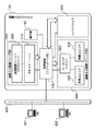
図1は、本実施形態における画像入出力システムの全体構成を示す図である。図示するように、画像入出力システム100は、画像入力装置(リーダ部)200、画像出力装置(プリンタ部)300、制御装置(コントローラ部)110、及び操作部150から構成されている。
FIG. 1 is a diagram illustrating an overall configuration of an image input / output system according to the present embodiment. As illustrated, the image input /
リーダ部200は、原稿画像を光学的に読み取り、画像データに変換する。このリーダ部200は、原稿を読み取るための機能を有するスキャナユニット210と、原稿用紙を搬送するための機能を有する原稿給紙(DF)ユニット250とで構成される。
The
プリンタ部300は、記録紙を搬送し、その上に画像データを可視画像として印字して装置外へ排紙する。このプリンタ部300は、複数サイズの記録紙カセットを備える給紙ユニット310と、画像形成された印字データを記録紙に転写、定着させる機能を有するマーキングユニット320と、印字された記録紙をソート、ステイプルして装置外へ出力する機能を有する排紙ユニット330とで構成される。
The
コントローラ部110は、リーダ部200、プリンタ部300、ハードディスク600と電気的に接続され、更にネットワーク400を介して複数のホストコンピュータ401、402と接続されている。ここで、ホストコンピュータ401、402は、パーソナルコンピュータ(PC)などの一般的なコンピュータであり、アプリケーションプログラムの印刷機能のうち、ユーザが後述する背表紙作成モードを指定すると、PCにインストールされているプリンタドライバによって背表紙作成モード設定画面がディスプレイに表示され、その設定画面からユーザは背表紙幅と背表紙のレイアウト(開き)と背表紙作成時の画像サイズ調整とを設定することができる。尚、この背表紙作成モードの詳細については更に後述する。
The
また、コントローラ部110はリーダ部200を制御して原稿の画像データを読み込み、プリンタ部300を制御してその画像データを記録用紙に出力する、コピー機能を提供する。更に、リーダ部200から読み取った画像データをコードデータに変換し、ネットワーク400を介してホストコンピュータへ送信するスキャナ機能、ホストコンピュータからネットワーク400を介して受信したコードデータを画像データに変換し、プリンタ部300に出力するプリンタ機能を有する。更に、画像データをハードディスク600に記憶する機能も有する。
The
操作部150は、コントローラ部110に接続され、液晶タッチパネルなどで構成され、画像入出力システムを操作するためのユーザI/Fを提供する。
The
図2は、リーダ部200及びプリンタ部300の構造を示す側断面図である。リーダ部200の原稿給送ユニット250は原稿を先頭順に1枚ずつプラテンガラス211上へ給送し、原稿の読み取り動作が終了した後、プラテンガラス211上の原稿を排出するものである。スキャナユニット210は原稿がプラテンガラス211上に搬送されると、ランプ212を点灯し、そして光学ユニット213の移動を開始させて原稿を露光走査する。この時の原稿からの反射光はミラー214、215、216、及びレンズ217によってCCDイメージセンサ(以下CCDという)218へ導かれる。このように、走査された原稿の画像はCCD218によって読み取られる。このCCD218から出力される画像データは、所定の処理が施された後、コントローラ部110へ転送される。
FIG. 2 is a side cross-sectional view illustrating the structure of the
一方、プリンタ部300のレーザドライバ321はレーザ発光部322を駆動するものであり、コントローラ部110から出力された画像データに応じたレーザ光をレーザ発光部322に発光させる。このレーザ光は感光ドラム323に照射され、感光ドラム323にはレーザ光に応じた潜像が形成される。この感光ドラム323の潜像の部分には現像器324によって現像剤が付着される。
On the other hand, the
そして、レーザ光の照射開始と同期したタイミングで、カセット311或いは312の何れかから記録紙を給紙して転写部325へ搬送し、感光ドラム323に付着された現像剤を記録紙に転写する。現像剤の乗った記録紙は定着部326に搬送され、定着部326の熱と圧力により現像剤が記像紙に定着される。その後、定着部326を通過した記録紙は排出ローラ327によって排出され、排紙ユニット330が排出された記録紙を束ねて記録紙の仕分けをしたり、仕分けされた記録紙のステイプルを行う。
Then, at a timing synchronized with the start of laser light irradiation, the recording paper is fed from either the
また、両面記録が設定されている場合は、排出ローラ327のところまで記録紙を搬送した後、排出ローラ327の回転方向を逆転させ、フラッパ328によって再給紙搬送路329へ導く。この再給紙搬送路329へ導かれた記録紙は上述したタイミングで転写部325へ給紙され、表面と同様に裏面への画像形成が行われる。
If double-sided recording is set, the recording paper is conveyed to the
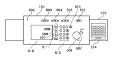
図3は、本実施形態における操作部150の構成の一例を示す図である。図3において、502は装置への電源オン/オフを示すパワーランプであり、パワースイッチ501の押下によって電源が投入されると点灯する。503はコピー機能選択キーであり、コピー機能を選択する際に押下する。504はファックス機能選択キーであり、ファックス機能を選択する際に押下する。505はパーソナルボックス選択キーであり、パーソナルボックス機能を選択する際に押下する。
FIG. 3 is a diagram illustrating an example of the configuration of the
512はテンキーであり、画像形成枚数の設定やモード設定などの数値入力に使用する。また、ファクシミリ設定画面では、電話番号の入力にも使用する。513はクリアキーであり、テンキー512で入力した設定を無効にする場合に使用する。508はリセットキーであり、設定された画像形成枚数や動作モード或いは選択給紙段等のモードを既定値に戻す場合に使用する。
506はスタートキーであり、画像形成を開始する場合に押下するキーである。507はストップキーであり、複写動作を停止する場合に使用する。509はガイドキーであり、あるキーの機能がわからない際に押下するキーであり、機能がわからないキーの説明は表示パネル516に表示する。
510はユーザモードキーであり、装置に対する各種設定を変更する際に使用するキーである。511は割り込みキーであり、画像形成動作中にユーザが他の作業をしたい場合に押下するキーである。514は20個のワンタッチダイヤルキーであり、ファクシミリ送信時にワンタッチでダイヤルする際に使用する。515は2枚の蓋であり、ワンタッチダイヤルキー514の各キー部分がくり抜かれた形状の2重の蓋になっている。
尚、不図示のセンサースイッチにより、2枚の蓋が閉じられた第1の状態と、1枚目の蓋が閉じられた第2の状態と、2枚の蓋が開いた第3の状態とを検出し、蓋の3つの開閉状態とワンタッチダイヤルキー514の組み合わせで、本実施形態では合計60個のキーが存在するのと同等の効果を持つ。
In addition, a first state in which two lids are closed by a sensor switch (not shown), a second state in which the first lid is closed, and a third state in which the two lids are opened. By combining the three open / closed states of the lid and the one-
516はタッチパネルであり、モード毎に設定画面が表示され、設定画面に描画されたキーに触れることで、各種の詳細な設定を行うことが可能である。
次に、上述した画像形成装置において背表紙画像を作成する背表紙作成モードについて説明する。 Next, a spine cover creation mode for creating a spine cover image in the above-described image forming apparatus will be described.
図4は、本実施形態における背表紙と画像のレイアウトを示す図である。図4において、604、614、624、634は背表紙作成で用いられる用紙を意味している。この背表紙用紙には、表表紙画像と裏表紙画像が背表紙幅の間隔で印刷され、背表紙幅に相当する部分は空白画像である。 FIG. 4 is a diagram illustrating a layout of a spine and an image in the present embodiment. In FIG. 4, 604, 614, 624, and 634 mean sheets used for spine creation. On this back cover paper, a front cover image and a back cover image are printed at intervals of the spine cover width, and a portion corresponding to the spine cover width is a blank image.
601、611、621、631はそれぞれ表表紙であり、背表紙画像に相当する画像「A」が印刷される。602、612、622、632はそれぞれ裏表紙であり、背表紙画像に相当する画像「B」が印刷される。603、613、623、633はユーザによって指定された背表紙幅分の空白領域である。
尚、上述の表表紙画像と裏表紙画像はユーザによって指定された背表紙のレイアウト、即ち、「開き」に応じて回転して配置される。また、背表紙作成モードにおけるプリント方法としては、表表紙画像と裏表紙画像、背表紙幅の空白画像とを連結した1つの画像をメモリ上で作成したものをプリントしても良いし、プリント時に排紙方向に従って表表紙或いは裏表紙をプリントした後、背表紙幅分の空白領域を形成するために、レーザを一定時間停止し、背表紙幅分の空白領域を形成した後、裏表紙或いは表表紙をプリントしても良い。 The front cover image and the back cover image described above are rotated and arranged in accordance with the layout of the back cover designated by the user, that is, “open”. Also, as a printing method in the back cover creation mode, an image created by linking a front cover image, a back cover image, and a blank image of the back cover width on the memory may be printed. After printing the front cover or back cover according to the paper discharge direction, in order to form a blank area for the width of the back cover, the laser is stopped for a certain period of time to form a blank area for the width of the back cover, and then the back cover or cover A cover may be printed.
次に、背表紙作成モードにおけるユーザ設定について説明する。本実施形態では、まず画像形成装置の操作部に表示される背表紙作成モード設定画面を例に説明する。 Next, user settings in the spine creation mode will be described. In the present embodiment, first, a back cover creation mode setting screen displayed on the operation unit of the image forming apparatus will be described as an example.
図5は、本実施形態における背表紙作成モード設定画面の一例を示す図である。ユーザは、この背表紙作成モード設定画面700で、背表紙幅と背表紙のレイアウト(開き)と背表紙作成時の画像サイズ調整とを設定することができる。
FIG. 5 is a diagram showing an example of a spine creation mode setting screen in the present embodiment. The user can set a spine cover width, a spine cover layout (opening), and image size adjustment at the time of spine creation on the spine cover creation
701はユーザが設定した背表紙幅の値を表示する領域である。ユーザは、プラスキー702又はマイナスキー703を押下することにより、1mm単位で背表紙幅を設定することができる。704〜707は右開き、左開き、上開き、下開きを設定するキーであり、ユーザは図4に示すような背表紙のレイアウトから何れか1つを選択可能である。
An
708は表表紙と裏表紙の画像サイズを調整するための第1の画像サイズ調整キーであり、用紙サイズに表表紙画像や裏表紙画像のサイズが一致するよう、表表紙画像と裏表紙画像の拡大縮小を行うものである。第1の画像サイズ調整キー708を設けることにより、表表紙画像や裏表紙画像が用紙より大きくても絵を切ることなく背表紙作成を行うことが可能になる。
709は裏表紙画像のサイズを表表紙画像のサイズに合わせるための第2の画像サイズ調整キーである。第2の画像サイズ調整キー709を設けることにより、リーダ部200やホストコンピュータ401から画像形成装置に入力される表表紙用原稿と裏表紙用原稿のサイズが異なっていても、画像形成装置側で表表紙画像と裏表紙画像の大きさを合わせることが可能となり、ユーザは事前に表表紙画像と裏表紙画像に相当する原稿を同じサイズにしておく必要がなくなり、背表紙作成の利便性を高めることができる。
710は設定キーであり、背表紙幅設定、開き設定、サイズ調整設定を有効化するためのキーである。711は戻るキーであり、背表紙作成モードをキャンセルし、不図示の基本画面に戻るためのキーである。
A setting
次に、画像形成装置の操作部150上の背表紙作成モード設定画面からユーザが諸設定を入力し、操作部150のスタートキー506が押下された場合、即ち、コピーモードでの背表紙作成処理について説明する。
Next, when the user inputs various settings from the spine creation mode setting screen on the
図6は、コピーモードでの背表紙作成処理を示すフローチャートである。まずステップS101において、コントローラ部110はメモリ上に設けた原稿枚数カウンタNの値を1にセットする。そして、ステップS102において、リーダ部200から読み取られたN枚目の原稿の画像データを入力してメモリに格納する。ここで、背表紙を作成するには原稿画像データが2枚分必要であるため、次のステップS103において、N枚目の原稿が最後の原稿か否かを判別する。判別した結果、最後の原稿でなければステップS104へ進み、N枚目と同様にリーダ部200から読み取られたN+1枚目の原稿の画像データを入力してメモリに格納する。また、判別した結果、N枚目の原稿が最後の原稿であればステップS105へ進み、N+1枚目のダミー画像(白画像)をメモリ上に作成する。
FIG. 6 is a flowchart showing spine cover creation processing in the copy mode. First, in step S101, the
次に、ステップS106において、図5に示した背表紙作成モード設定画面700にてユーザが設定した「背表紙幅」、「開き」、「画像サイズ調整」の各設定値を参照する。そして、ステップS107において、ステップS106で参照した設定値に基づいて表表紙と裏表紙の画像配置処理を行う。尚、この画像配置処理の詳細については、図7を参照して更に後述する。
In step S106, the setting values of “back cover width”, “open”, and “image size adjustment” set by the user on the spine creation
次に、ステップS108において、ステップS107での画像配置に基づいてプリント用紙にプリントを行う。このとき、表表紙画像と裏表紙画像、背表紙幅の空白画像を連結した1つの画像としてメモリ上で作成したものをプリントしても良いし、またプリント時に排紙方向に従って表表紙或いは裏表紙をプリントした後、背表紙幅分の空白領域を形成するためにレーザを一定時間停止してプリント用紙の搬送を進め、背表紙幅分の空白領域を形成した後、裏表紙或いは表表紙をプリントしても良い。 Next, in step S108, printing is performed on a print sheet based on the image layout in step S107. At this time, a front cover image, a back cover image, and a blank image having a width of the back cover may be printed on the memory as one image, or the front cover or the back cover may be printed according to the paper discharge direction at the time of printing. After printing, the laser is stopped for a certain period of time to form a blank area for the width of the back cover, and the print paper is transported. After forming a blank area for the width of the back cover, the back cover or the front cover is printed. You may do it.
次に、ステップS109において、次原稿があるか否かを判別する。ここで、次原稿があればステップS110へ進み、原稿枚数カウンタNの値に2を加え、ステップS102に戻り、上述の背表紙作成処理を繰り返す。また、次原稿がなければ、背表紙作成処理を終了する。 In step S109, it is determined whether there is a next original. If there is a next original, the process proceeds to step S110, 2 is added to the value of the original number counter N, the process returns to step S102, and the above-described spine cover creation process is repeated. If there is no next manuscript, the spine creation process is terminated.
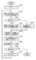
図7は、図6に示したS107での背表紙画像配置処理を示すフローチャートである。まず、ステップS201において、裏表紙画像のサイズが表表紙画像のサイズより大きいか否かを判断する。具体的には、図5に示す第2の画像調整キーが有効になっている場合に、表表紙画像の副走査幅より裏表紙画像の副走査幅が大きいか、表表紙画像の主走査幅より裏表紙画像の主走査幅が大きいか否かを判別する。そして、どちらかに該当する場合はステップS202へ進み、表表紙画像のサイズで裏表紙画像をカッティングする。また、図5に示す第2の画像調整キーが有効になっていない場合はステップS203へ進む。このステップS203では、図5に示す用紙サイズに表表紙画像及び裏表紙画像のサイズを拡大縮小させるか否かの第1の画像調整設定がなされているか否かを判別する。 FIG. 7 is a flowchart showing the spine image arrangement processing in S107 shown in FIG. First, in step S201, it is determined whether the size of the back cover image is larger than the size of the cover image. Specifically, when the second image adjustment key shown in FIG. 5 is enabled, the sub-scanning width of the back cover image is larger than the sub-scanning width of the front cover image, or the main scanning width of the front cover image. It is further determined whether or not the main scanning width of the back cover image is larger. If either of them is true, the process proceeds to step S202, and the back cover image is cut with the size of the front cover image. If the second image adjustment key shown in FIG. 5 is not enabled, the process proceeds to step S203. In step S203, it is determined whether or not the first image adjustment setting is made as to whether or not to enlarge or reduce the size of the front cover image and the back cover image to the paper size shown in FIG.
尚、上述のステップS202では、表表紙画像と裏表紙画像のサイズを合わせた状態であり、それらの副走査幅と用紙サイズの副走査幅は一致していない場合がある。そこで、ステップS203において、第1の画像調整設定がなされていると判断するとステップS204へ進み、第1の画像調整がなされていない場合はステップS210へ進む。 In step S202 described above, the sizes of the front cover image and the back cover image are the same, and the sub-scanning width and the paper size may not match. Therefore, if it is determined in step S203 that the first image adjustment setting has been made, the process proceeds to step S204, and if the first image adjustment has not been performed, the process proceeds to step S210.
このステップS204では、表表紙画像の副走査幅が用紙の副走査幅より大きいと判別された場合はステップS205へ進み、表表紙画像の副走査幅が用紙の副走査幅と等しくなるように表表紙画像を縮小し、また表表紙画像の副走査幅が用紙の副走査幅より小さいと判別された場合はステップS206へ進み、表表紙画像の副走査幅が用紙の副走査幅と等しくなるように表表紙画像を拡大する。 In this step S204, if it is determined that the sub-scanning width of the front cover image is larger than the sub-scanning width of the paper, the process proceeds to step S205, and the front cover image is displayed so that the sub-scanning width becomes equal to the sub-scanning width of the paper. If the cover image is reduced and it is determined that the sub-scanning width of the cover-cover image is smaller than the sub-scanning width of the paper, the process proceeds to step S206, and the sub-scanning width of the cover-cover image becomes equal to the sub-scanning width of the paper. Enlarge the cover image.
次に、ステップS207において、裏表紙画像の副走査幅が用紙の副走査幅より大きいと判別された場合はステップS208へ進み、裏表紙画像の副走査幅が用紙の副走査幅と等しくなるように裏表紙画像を縮小し、また裏表紙画像の副走査幅が用紙の副走査幅より小さいと判別された場合はステップS209へ進み、裏表紙画像の副走査幅が用紙の副走査幅と等しくなるように裏表紙画像を拡大する。 Next, when it is determined in step S207 that the sub-scanning width of the back cover image is larger than the sub-scanning width of the paper, the process proceeds to step S208, and the sub-scanning width of the back cover image becomes equal to the sub-scanning width of the paper. If the back cover image is reduced and the sub-scanning width of the back cover image is determined to be smaller than the sub-scanning width of the paper, the process proceeds to step S209, where the sub-scanning width of the back cover image is equal to the sub-scanning width of the paper. Enlarge the back cover image so that
次に、ステップS210において、図5に示す背表紙のレイアウト(開き)設定に従い、図4に示す画像配置となるように、メモリに格納されている表表紙画像及び裏表紙画像を回転させる。そして、ステップS211において、表表紙画像及び裏表紙画像の間に、図5に示す設定画面で入力された背表紙幅分の空白領域を設け、表表紙画像と裏表紙画像の画像配置処理を終了する。 Next, in step S210, the front cover image and the back cover image stored in the memory are rotated so that the image layout shown in FIG. 4 is obtained according to the layout (opening) setting of the back cover shown in FIG. In step S211, a blank area corresponding to the width of the back cover inputted on the setting screen shown in FIG. 5 is provided between the front cover image and the back cover image, and the image layout processing of the front cover image and the back cover image is completed. To do.
次に、ホストコンピュータにおいて、プリンタドライバが図5に示す背表紙作成モード設定画面と同様な設定画面をユーザに提供し、ユーザがその設定画面で背表紙幅と背表紙のレイアウト(開き)と背表紙作成時の画像サイズ調整とを設定した後、画像形成装置がホストコンピュータからPDLの印刷データを受信して背表紙を作成する背表紙作成処理について説明する。 Next, in the host computer, the printer driver provides the user with a setting screen similar to the back cover creation mode setting screen shown in FIG. 5, and the user uses the setting screen to display the back cover width, the back cover layout (open), and the back cover. A spine cover creation process in which the image forming apparatus receives PDL print data from the host computer and creates a spine cover after setting the image size adjustment at the time of creating the cover will be described.
図8は、PDLモードでの背表紙作成処理を示すフローチャートである。まずステップS301において、コントローラ部110はメモリ上に設けた画像枚数カウンタNの値を1にセットする。そして、ステップS302において、受信したPDLの印刷データからN枚目の画像を解析し、レンダリングを行ってメモリに画像データを格納する。ここで、背表紙を作成するには画像データが2枚分必要であるため、次のステップS303において、N枚目の画像が最後の画像か否かを判別する。判別した結果、最後の画像でなければステップS304へ進み、N枚目と同様に、N+1枚目の画像を解析し、レンダリングを行ってメモリに画像データを格納する。また、判別した結果、N枚目の画像が最後の画像であればステップS305へ進み、N+1枚目のダミー画像(白画像)をメモリ上に作成する。
FIG. 8 is a flowchart showing the spine creation process in the PDL mode. First, in step S301, the
次に、ステップS306において、プリンタドライバによって提供される図5と同様な背表紙作成モード設定画面にてユーザが設定した「背表紙幅」、「開き」、「画像サイズ調整」の各設定値を取得する。そして、ステップS307において、ステップS306で取得した設定値に基づいて表表紙と裏表紙の画像配置を行う。尚、この画像配置処理は、図7を用いて説明した処理と同様であり、その説明は省略する。 Next, in step S306, the setting values of “back cover width”, “open”, and “image size adjustment” set by the user on the back cover creation mode setting screen similar to FIG. 5 provided by the printer driver are displayed. get. In step S307, the front and back cover images are arranged based on the setting value acquired in step S306. Note that this image arrangement process is the same as the process described with reference to FIG.
次に、ステップS308において、ステップS307での画像配置に基づいてプリント用紙にプリントを行う。このとき、表表紙画像と裏表紙画像、背表紙幅の空白画像を連結した1つの画像としてメモリ上で作成したものをプリントしても良いし、またプリント時に排紙方向に従って表表紙或いは裏表紙をプリントした後、背表紙幅分の空白領域を形成するためにレーザを一定時間停止してプリント用紙の搬送を進め、背表紙幅分の空白領域を形成した後、裏表紙或いは表表紙をプリントしても良い。 Next, in step S308, printing is performed on a print sheet based on the image layout in step S307. At this time, a front cover image, a back cover image, and a blank image having a width of the back cover may be printed on the memory as one image, or the front cover or the back cover may be printed according to the paper discharge direction at the time of printing. After printing, the laser is stopped for a certain period of time to form a blank area for the width of the back cover, and the print paper is transported. After forming a blank area for the width of the back cover, the back cover or the front cover is printed. You may do it.
次に、ステップS309において、次画像があるか否かを判別する。ここで、次画像があればステップS310へ進み、画像枚数カウンタNの値に2を加え、ステップS302に戻り、上述の背表紙作成処理を繰り返す。また、次画像がなければ、背表紙作成処理を終了する。 Next, in step S309, it is determined whether there is a next image. If there is a next image, the process proceeds to step S310, 2 is added to the value of the image number counter N, the process returns to step S302, and the above-described spine cover creation process is repeated. If there is no next image, the spine cover creation process is terminated.
以上説明したように、従来の画像形成装置では、入力画像2枚のうちのどちらを表表紙或いは裏表紙にするかをユーザが指定できなかったため、画像形成装置に対して入力する画像の順番を意識せねばならず、操作ミスを起こし易いものであったが、ユーザが背表紙画像の開きを指定できるようにすることで、ユーザは画像入力の順番を意識せずに容易に背表紙を作成でき、操作性を向上させることができる。 As described above, in the conventional image forming apparatus, the user cannot designate which of the two input images is the front cover or the back cover, and therefore the order of images input to the image forming apparatus is determined. Although it was necessary to be conscious and it was easy to cause operational mistakes, by allowing the user to specify the opening of the back cover image, the user can easily create a back cover without being aware of the order of image input And operability can be improved.
特に、第1の画像サイズ調整キーを設けることにより、表表紙画像や裏表紙画像が用紙より大きくても絵を切ることなく背表紙作成を行うことが可能となる。 In particular, by providing the first image size adjustment key, it is possible to create a back cover without cutting a picture even if the front cover image and the back cover image are larger than the paper.
また、第2の画像サイズ調整キーを設けることにより、スキャナや外部装置から画像形成装置に入力する表表紙用画像と裏表紙用画像のサイズが異なっていても、画像形成装置側で表表紙画像と裏表紙画像の大きさを合わせることが可能となり、ユーザが事前に表表紙画像と裏表紙画像に相当する画像を同じサイズにしておく必要がなくなり、背表紙作成の利便性を向上させることができる。 Further, by providing the second image size adjustment key, even if the sizes of the front cover image and the back cover image input to the image forming apparatus from a scanner or an external device are different, the front cover image on the image forming apparatus side. The size of the back cover image can be matched with the size of the back cover image, so that the user does not have to make the images corresponding to the front cover image and the back cover image the same size in advance, and the convenience of creating the back cover can be improved. it can.
尚、本発明は複数の機器(例えば、ホストコンピュータ,インターフェース機器,リーダ,プリンタなど)から構成されるシステムに適用しても、1つの機器からなる装置(例えば、複写機,ファクシミリ装置など)に適用しても良い。 Even if the present invention is applied to a system composed of a plurality of devices (for example, a host computer, an interface device, a reader, a printer, etc.), it is applied to an apparatus (for example, a copier, a facsimile machine, etc.) composed of a single device. It may be applied.
また、本発明の目的は前述した実施形態の機能を実現するソフトウェアのプログラムコードを記録した記録媒体を、システム或いは装置に供給し、そのシステム或いは装置のコンピュータ(CPU若しくはMPU)が記録媒体に格納されたプログラムコードを読出し実行することによっても、達成されることは言うまでもない。 Another object of the present invention is to supply a recording medium in which a program code of software realizing the functions of the above-described embodiments is recorded to a system or apparatus, and the computer (CPU or MPU) of the system or apparatus stores the recording medium in the recording medium. Needless to say, this can also be achieved by reading and executing the programmed program code.
この場合、記録媒体から読出されたプログラムコード自体が前述した実施形態の機能を実現することになり、そのプログラムコードを記憶した記録媒体は本発明を構成することになる。 In this case, the program code itself read from the recording medium realizes the functions of the above-described embodiment, and the recording medium storing the program code constitutes the present invention.
このプログラムコードを供給するための記録媒体としては、例えばフロッピー(登録商標)ディスク,ハードディスク,光ディスク,光磁気ディスク,CD−ROM,CD−R,磁気テープ,不揮発性のメモリカード,ROMなどを用いることができる。 As a recording medium for supplying the program code, for example, a floppy (registered trademark) disk, a hard disk, an optical disk, a magneto-optical disk, a CD-ROM, a CD-R, a magnetic tape, a nonvolatile memory card, a ROM, or the like is used. be able to.
また、コンピュータが読出したプログラムコードを実行することにより、前述した実施形態の機能が実現されるだけでなく、そのプログラムコードの指示に基づき、コンピュータ上で稼働しているOS(オペレーティングシステム)などが実際の処理の一部又は全部を行い、その処理によって前述した実施形態の機能が実現される場合も含まれることは言うまでもない。 Further, by executing the program code read by the computer, not only the functions of the above-described embodiments are realized, but also an OS (operating system) operating on the computer based on the instruction of the program code. It goes without saying that a case where the function of the above-described embodiment is realized by performing part or all of the actual processing and the processing is included.
更に、記録媒体から読出されたプログラムコードが、コンピュータに挿入された機能拡張ボードやコンピュータに接続された機能拡張ユニットに備わるメモリに書込まれた後、そのプログラムコードの指示に基づき、その機能拡張ボードや機能拡張ユニットに備わるCPUなどが実際の処理の一部又は全部を行い、その処理によって前述した実施形態の機能が実現される場合も含まれることは言うまでもない。 Further, after the program code read from the recording medium is written in a memory provided in a function expansion board inserted into the computer or a function expansion unit connected to the computer, the function expansion is performed based on the instruction of the program code. It goes without saying that the CPU or the like provided in the board or the function expansion unit performs part or all of the actual processing and the functions of the above-described embodiments are realized by the processing.
100 画像入出力システム
110 制御装置(コントローラ部)
150 操作部
200 画像入力装置(リーダ部)
210 スキャナユニット
250 原稿給紙(DF)ユニット
300 画像出力装置(プリンタ部)
310 給紙ユニット
320 マーキングユニット
330 排紙ユニット
400 ネットワーク
401 ホストコンピュータ
402 ホストコンピュータ
501 パワースイッチ
502 パワーランプ
503 コピー機能選択キー
504 ファックス機能選択キー
505 パーソナルボックス選択キー
506 スタートキー
507 ストップキー
508 リセットキー
509 ガイドキー
510 ユーザモードキー
511 割り込みキー
512 テンキー
513 クリアキー
514 ワンタッチダイヤルキー
515 2枚の蓋
516 タッチパネル
600 ハードディスク
100 Image Input /
150
210
310
Claims (8)
前記第1画像と前記第2画像とを入力する入力手段と、
前記第1画像のサイズより前記第2画像のサイズが大きい場合に、前記第2画像を前記第1画像とサイズが等しくなるように切り取る切取手段と、
前記入力手段により入力された前記第1画像と前記切取手段により切り取られた前記第2画像とに基づいた前記表紙用の画像を前記表紙用の記録紙上に形成させるよう前記画像形成手段を制御する制御手段と
を有することを特徴とする画像形成装置。 An image forming apparatus having an image forming unit capable of forming a cover image based on a first image and a second image on a cover recording paper that wraps a recording paper bundle composed of a plurality of recording papers. There,
Input means for inputting the first image and the second image;
If the size of size than the second image of the first image is larger, the cut section cut out the second image to the first image and the size are equal,
Controlling the image forming means to form an image for the cover on the recording paper for the cover based on the first image input by the input means and the second image cut by the cutting means; An image forming apparatus comprising: a control unit.
前記制御手段は、前記変倍手段により変倍された前記第1画像と前記切取手段により切り取られ前記変倍手段により変倍された前記第2画像とに基づいた前記表紙用の画像を前記表紙用の記録紙上に形成させるよう前記画像形成手段を制御することを特徴とする請求項1に記載の画像形成装置。 The first image input by the input means and the second image cut by the cutting means are respectively scaled so that the size of the cover image matches the size of the cover recording paper. It further has a zooming means,
The control unit is configured to display the cover image based on the first image scaled by the scaling unit and the second image cropped by the cropping unit and scaled by the scaling unit. The image forming apparatus according to claim 1, wherein the image forming unit is controlled so as to be formed on a recording sheet.
前記制御手段は、前記受付手段で受け付けたレイアウトの設定に基づき、前記入力手段により入力された前記第1画像と前記切取手段により切り取られた前記第2画像とに基づいた前記表紙用の画像を前記表紙用の記録紙上に形成させるよう前記画像形成手段を制御することを特徴とする請求項1又は2に記載の画像形成装置。 A reception unit for receiving layout settings of the first image and the second image;
The control means is configured to display the cover image based on the first image input by the input means and the second image cut by the cutting means based on the layout setting received by the receiving means. the image forming apparatus according to claim 1 or 2, wherein the controller controls the image forming means so as to form on the recording sheet for the cover.
前記第1画像と前記第2画像とを入力する入力工程と、
前記第1画像のサイズより前記第2画像のサイズが大きい場合に、前記第2画像を前記第1画像とサイズが等しくなるように切り取る切取工程と、
前記入力工程において入力された前記第1画像と前記切取工程において切り取られた前記第2画像とに基づいた前記表紙用の画像を前記表紙用の記録紙上に形成させるよう前記画像形成手段を制御する制御工程と
を有することを特徴とする制御方法。 An image forming apparatus having an image forming unit capable of forming a cover image based on a first image and a second image on a cover sheet that wraps a bundle of recording sheets composed of a plurality of recording sheets. Control method executed by
An input step of inputting the first image and the second image;
If the size of size than the second image of the first image is larger, the step cut crop the second image to the first image and the size are equal,
The image forming means is controlled to form an image for the cover based on the first image input in the input step and the second image cut in the cut step on the cover recording paper. A control method comprising: a control step.
Priority Applications (1)
| Application Number | Priority Date | Filing Date | Title |
|---|---|---|---|
| JP2004093165A JP4328655B2 (en) | 2004-03-26 | 2004-03-26 | Image forming apparatus and control method |
Applications Claiming Priority (1)
| Application Number | Priority Date | Filing Date | Title |
|---|---|---|---|
| JP2004093165A JP4328655B2 (en) | 2004-03-26 | 2004-03-26 | Image forming apparatus and control method |
Publications (3)
| Publication Number | Publication Date |
|---|---|
| JP2005286392A JP2005286392A (en) | 2005-10-13 |
| JP2005286392A5 JP2005286392A5 (en) | 2007-05-31 |
| JP4328655B2 true JP4328655B2 (en) | 2009-09-09 |
Family
ID=35184356
Family Applications (1)
| Application Number | Title | Priority Date | Filing Date |
|---|---|---|---|
| JP2004093165A Expired - Fee Related JP4328655B2 (en) | 2004-03-26 | 2004-03-26 | Image forming apparatus and control method |
Country Status (1)
| Country | Link |
|---|---|
| JP (1) | JP4328655B2 (en) |
Families Citing this family (4)
| Publication number | Priority date | Publication date | Assignee | Title |
|---|---|---|---|---|
| JP4600302B2 (en) * | 2006-01-24 | 2010-12-15 | コニカミノルタビジネステクノロジーズ株式会社 | Image forming apparatus, image forming system, and program |
| JP4848778B2 (en) * | 2006-01-26 | 2011-12-28 | コニカミノルタビジネステクノロジーズ株式会社 | Image forming apparatus |
| JP5100157B2 (en) * | 2007-03-05 | 2012-12-19 | キヤノン株式会社 | Image forming apparatus |
| JP6699347B2 (en) * | 2016-05-20 | 2020-05-27 | 富士ゼロックス株式会社 | Imposition processing device |
Family Cites Families (8)
| Publication number | Priority date | Publication date | Assignee | Title |
|---|---|---|---|---|
| JPH0670136A (en) * | 1992-08-21 | 1994-03-11 | Canon Inc | Facsimile receiver |
| JP3733238B2 (en) * | 1998-04-15 | 2006-01-11 | キヤノン株式会社 | Image processing device |
| JP2000184154A (en) * | 1998-12-18 | 2000-06-30 | Canon Inc | Image processor and method for controlling the same |
| JP2000332987A (en) * | 1999-05-19 | 2000-11-30 | Canon Inc | Image forming device |
| JP2001197286A (en) * | 2000-01-06 | 2001-07-19 | Minolta Co Ltd | Image processor and image processing method |
| JP4014790B2 (en) * | 2000-08-11 | 2007-11-28 | セイコーエプソン株式会社 | Medium recording print preview program, print preview apparatus, and print preview method |
| JP2002361967A (en) * | 2001-06-05 | 2002-12-18 | Dainippon Screen Mfg Co Ltd | Printing system, controller, printing method, recording medium and program |
| JP3919544B2 (en) * | 2002-01-16 | 2007-05-30 | キヤノン株式会社 | Image processing apparatus and image processing apparatus control method |
-
2004
- 2004-03-26 JP JP2004093165A patent/JP4328655B2/en not_active Expired - Fee Related
Also Published As
| Publication number | Publication date |
|---|---|
| JP2005286392A (en) | 2005-10-13 |
Similar Documents
| Publication | Publication Date | Title |
|---|---|---|
| JP4323839B2 (en) | Image input / output device, image input / output system, storage medium, operation method suitable for image input / output system, and operation screen display method | |
| JP5127233B2 (en) | Image forming apparatus and image forming method | |
| JP2008217576A (en) | Device having liquid crystal touch panel and operation key | |
| JP4181661B2 (en) | Image processing apparatus, data processing method for image processing apparatus, and storage medium storing computer-readable program | |
| JP4728850B2 (en) | Image forming apparatus and control method thereof | |
| JP2007109155A (en) | Image forming apparatus | |
| JP5830490B2 (en) | Image forming apparatus | |
| JP4328655B2 (en) | Image forming apparatus and control method | |
| JP2007122279A (en) | Image processor, image processing method, and program | |
| JP2007083439A (en) | Image output unit | |
| JP6470071B2 (en) | Image processing device | |
| US7006240B1 (en) | Image forming apparatus for printing two original documents on both sides of a paper | |
| JP4343488B2 (en) | Image input system and control method thereof | |
| JP4796272B2 (en) | Image forming apparatus | |
| JP2006180044A (en) | Image processor | |
| JP2002356020A (en) | Imaging apparatus, imaging method, recording medium, and program | |
| JP2008074067A (en) | Image forming apparatus | |
| JP2001356646A (en) | Image forming device, its control method and recording medium | |
| JP4078186B2 (en) | Data processing apparatus, data processing method, program, and storage medium | |
| JP2005234253A (en) | Image forming apparatus | |
| JP2001235976A (en) | Image forming device, image forming system, image forming control method and storing medium | |
| JP2003127508A (en) | Off-line printing method, method for generating output control data, and software | |
| JP3592029B2 (en) | Image output device and image output method | |
| JP2006325176A (en) | Apparatus, system, method and program for forming image | |
| JP2005197831A (en) | Image processing method, image processing apparatus, program and storage medium |
Legal Events
| Date | Code | Title | Description |
|---|---|---|---|
| A621 | Written request for application examination |
Free format text: JAPANESE INTERMEDIATE CODE: A621 Effective date: 20070322 |
|
| A521 | Written amendment |
Free format text: JAPANESE INTERMEDIATE CODE: A523 Effective date: 20070406 |
|
| A977 | Report on retrieval |
Free format text: JAPANESE INTERMEDIATE CODE: A971007 Effective date: 20080701 |
|
| A131 | Notification of reasons for refusal |
Free format text: JAPANESE INTERMEDIATE CODE: A131 Effective date: 20080714 |
|
| A521 | Written amendment |
Free format text: JAPANESE INTERMEDIATE CODE: A523 Effective date: 20080912 |
|
| A131 | Notification of reasons for refusal |
Free format text: JAPANESE INTERMEDIATE CODE: A131 Effective date: 20090319 |
|
| A521 | Written amendment |
Free format text: JAPANESE INTERMEDIATE CODE: A523 Effective date: 20090513 |
|
| TRDD | Decision of grant or rejection written | ||
| A01 | Written decision to grant a patent or to grant a registration (utility model) |
Free format text: JAPANESE INTERMEDIATE CODE: A01 Effective date: 20090605 |
|
| A01 | Written decision to grant a patent or to grant a registration (utility model) |
Free format text: JAPANESE INTERMEDIATE CODE: A01 |
|
| A61 | First payment of annual fees (during grant procedure) |
Free format text: JAPANESE INTERMEDIATE CODE: A61 Effective date: 20090615 |
|
| FPAY | Renewal fee payment (event date is renewal date of database) |
Free format text: PAYMENT UNTIL: 20120619 Year of fee payment: 3 |
|
| R150 | Certificate of patent or registration of utility model |
Free format text: JAPANESE INTERMEDIATE CODE: R150 |
|
| FPAY | Renewal fee payment (event date is renewal date of database) |
Free format text: PAYMENT UNTIL: 20120619 Year of fee payment: 3 |
|
| FPAY | Renewal fee payment (event date is renewal date of database) |
Free format text: PAYMENT UNTIL: 20130619 Year of fee payment: 4 |
|
| LAPS | Cancellation because of no payment of annual fees |