JP4296515B2 - Operation device for motorcycle game machine - Google Patents
Operation device for motorcycle game machine Download PDFInfo
- Publication number
- JP4296515B2 JP4296515B2 JP2006191566A JP2006191566A JP4296515B2 JP 4296515 B2 JP4296515 B2 JP 4296515B2 JP 2006191566 A JP2006191566 A JP 2006191566A JP 2006191566 A JP2006191566 A JP 2006191566A JP 4296515 B2 JP4296515 B2 JP 4296515B2
- Authority
- JP
- Japan
- Prior art keywords
- vehicle body
- support shaft
- handle
- operator
- seat portion
- Prior art date
- Legal status (The legal status is an assumption and is not a legal conclusion. Google has not performed a legal analysis and makes no representation as to the accuracy of the status listed.)
- Expired - Fee Related
Links
Images


Description
本発明は、コンピュータにより制御された映像をディスプレイ上に投影して行うゲーム機の操作装置に関するものである。より具体的には、本発明は、ディスプレイの前方にオートバイを模した形状の操作装置を配置し、操作者がこの操作装置に跨ってオートバイ乗用時と同様な姿勢で操作を行うことにより、ディスプレイ上に投影される画像を変化させるようにしたオートバイゲーム機の操作装置に関する。 The present invention relates to an operating device for a game machine that projects an image controlled by a computer on a display. More specifically, in the present invention, an operation device having a shape imitating a motorcycle is arranged in front of the display, and an operator performs an operation in the same posture as riding a motorcycle across the operation device. The present invention relates to an operating device for a motorcycle game machine in which an image projected thereon is changed.
従来から、コンピュータ映像を利用したゲーム機の一つとして、オートバイゲームが知られている。このオートバイゲームは、ディスプレイ上に投影されるオートバイのレースシーンを、ディスプレイ前方に設けられた操作装置によって制御することにより、得点を競うものである。このオートバイゲーム機の操作装置には単なるレバーやボタンなどの入力装置を使用したものもあるが、特に、実物のオートバイを模した形状のものは、臨場感にあふれていることから人気が高い。 Conventionally, a motorcycle game is known as one of game machines using computer video. In this motorcycle game, a motorcycle race scene projected on a display is controlled by an operating device provided in front of the display to compete for scores. Some of the operation devices of this motorcycle game machine use an input device such as a simple lever or button, but in particular, the shape imitating a real motorcycle is very popular because it is full of realism.
このようなオートバイ型の操作装置として、特開平1−214385号公報や特開平4−22383号公報に記載のものが知られている。このような従来技術の操作装置は、床面に設置されたベースにオートバイの型の車体を左右に傾斜可能に支持し、この車体にハンドルを一体に設けたものである。この従来の操作装置では、ハンドルの両端に設けられたスロットルレバーやブレーキを操作することにより、ディスプレイ上に投影されるオートバイの前景の移動速度を制御し、車体全体を左右に傾けることにより、ディスプレイ上におけるオートバイの進行方向を制御するようになっている。 As such a motorcycle type operation device, those described in Japanese Patent Laid-Open Nos. 1-2214385 and 4-22383 are known. Such a conventional operation device is such that a motorcycle-type vehicle body is supported on a base installed on a floor surface so as to be tiltable to the left and right, and a handle is integrally provided on the vehicle body. In this conventional operating device, the moving speed of the motorcycle foreground projected on the display is controlled by operating throttle levers and brakes provided at both ends of the handle, and the entire vehicle body is tilted to the left and right. It is designed to control the direction of motorcycle travel.
ところが、以上のような従来技術においては、左右に傾斜する車体にハンドルを一体に設けているため、操作者が車体に跨った場合に、床面やベースから足を離し、車体に設けられたステップに足を乗せて操作することが不可能である。すなわち、車体にハンドルを一体に設けた操作装置を操作する際に、操作者が床面やベースから足を離してステップに足を乗せた場合、操作者は、車体に全体重を預ける形となる。そして、このように操作者が車体に全体重を預けた状態では、一旦車体を傾斜させると、車体を引き起こして元の垂直な状態に復帰させることは困難である。そのため、このような操作装置を操作する際、操作者は、両足を床面やベースにつけたままにしておき、車体を傾けた場合には、足の力を利用して車体を垂直な状態に引き起こすことになる。 However, in the prior art as described above, since the handle is integrally provided on the vehicle body that is inclined to the left and right, when the operator straddles the vehicle body, the operator removes his / her foot from the floor or base and is provided on the vehicle body. It is impossible to operate with a foot on the step. That is, when operating the operating device with the handle integrated with the vehicle body, if the operator removes his / her foot from the floor or base and puts his / her foot on the step, the operator can leave the entire weight on the vehicle body. Become. In such a state where the operator deposits the entire weight on the vehicle body, once the vehicle body is tilted, it is difficult to cause the vehicle body to return to the original vertical state. Therefore, when operating such an operating device, the operator keeps both feet on the floor and base, and when the vehicle body is tilted, it uses the power of the foot to bring the vehicle body into a vertical state. Will cause.
しかし、実際にオートバイに乗車する場合には、オートバイの車体に設けられたステップに足を乗せ、地面から足を離した状態で運転する。したがって、以上のような従来の操作装置において、足を床面やベースに付けた状態で操作を行うことは、現実のオートバイの運転感覚とはかけ離れたものであり、ゲームの臨場感を損ねるものである。 However, when actually riding a motorcycle, the user puts his / her foot on a step provided on the body of the motorcycle and drives with the foot off the ground. Therefore, in the conventional operating device as described above, operating with the feet attached to the floor or base is far from the actual driving feeling of a motorcycle, and impairs the realism of the game. It is.
また、従来の操作装置は、車体を左右に傾斜するに当たり、床面近くの低い位置に床面と平行に支軸を設け、この支軸によって車体の下部を回動自在に支持している。そのため、車体を傾斜した際に、操作者の頭部は支軸を中心として大きく左右に回動し、車体前方に配置されているディスプレイの中心から大きく外れてしまい、ディスプレイ上の画像が見難くなる欠点がある。 Further, in the conventional operation device, when the vehicle body is tilted to the left and right, a support shaft is provided in parallel with the floor surface at a low position near the floor surface, and the lower portion of the vehicle body is rotatably supported by the support shaft. For this reason, when the vehicle body is tilted, the operator's head largely rotates to the left and right around the support shaft, and is greatly out of the center of the display arranged in front of the vehicle body, making it difficult to see the image on the display. There are disadvantages.
しかも、現実にオートバイがコースの曲線部分を走行する場合、車体を単に左右に傾けるのではなく、車体と前輪とをコースの方向に合わせて曲げる操作も必要である。そのため、従来の操作装置において、単に車体を左右に傾けるだけの操作を行うことは、現実のオートバイの運転時の車体姿勢に比べてかなり不自然で違和感があり、このことも、ゲームの臨場感を損ねている。 Moreover, when a motorcycle actually travels on a curved portion of a course, it is necessary to bend the vehicle body and front wheels in accordance with the course direction, instead of simply tilting the vehicle body to the left and right. For this reason, it is quite unnatural and uncomfortable to perform the operation of simply tilting the vehicle body to the left and right in the conventional operation device, compared to the vehicle body posture when driving an actual motorcycle. Is undermined.
さらに、現実のオートバイを運転した場合は、アクセルとブレーキの操作によるオートバイの速度や加速度に応じて、コースの曲線部分を通過する車体に加わる遠心力などが異なってくるため、車体を傾斜させるのに必要な力も異なってくる。しかし、従来の操作装置においては、このような、操作に応じた車体からのリアクションを得ることができず、車体を傾斜させるのに必要な力も一定であるため、この点でも、現実のオートバイの運転感覚とはかけ離れたものであり、ゲームの臨場感を損ねている。 In addition, when driving an actual motorcycle, the centrifugal force applied to the vehicle body that passes through the curved part of the course varies depending on the speed and acceleration of the motorcycle due to the operation of the accelerator and brake. The power required for this will also vary. However, in the conventional operating device, such a reaction from the vehicle body according to the operation cannot be obtained, and the force necessary to tilt the vehicle body is constant, so in this respect as well, It is far from driving sensation and detracts from the realism of the game.
本発明の目的は、前記のような従来技術の問題点を解決して、より現実のオートバイの運転感覚に近い、臨場感にあふれた操作を行うことのでき、しかも、小型・簡略なオートバイゲーム機の操作装置を提供することである。より具体的には、本発明の目的は、次のような4つの特徴(1)〜(4)の少なくとも一つを有するオートバイゲーム機の操作装置を提供することである。 The object of the present invention is to solve the problems of the prior art as described above, and to perform an operation full of realism that is closer to the driving feeling of a real motorcycle, and is a small and simple motorcycle game. It is to provide a machine operating device. More specifically, an object of the present invention is to provide an operating device for a motorcycle game machine having at least one of the following four features (1) to (4).
(1)ステップに足をのせた状態での操作性の確保:操作者が車体のステップに足を乗せた状態で車体を左右に傾斜させて操作を行うことができる。 (1) Ensuring operability with a foot placed on a step: An operator can perform an operation by tilting the vehicle body to the left or right with the foot placed on the vehicle body step.
(2)ディスプレイに対する操作者の頭部位置の維持:左右に車体を傾けた場合でも、操作者の頭部の移動を小さく抑えることができる。 (2) Maintenance of the operator's head position with respect to the display: Even when the vehicle body is tilted left and right, the movement of the operator's head can be kept small.
(3)現実に近い車体姿勢の確保:現実のオートバイを運転している車体姿勢に近く、違和感の少ない操作を行うことができる。 (3) Ensuring vehicle body posture close to reality: Operation close to the vehicle body posture driving an actual motorcycle can be performed with little discomfort.
(4)現実に近いリアクションの確保:ディスプレイ上に表示されたコースの状況あるいはアクセルやブレーキの操作に応じて、車体からのより現実に近いリアクションを得ることができる。 (4) Ensuring reaction closer to reality: A reaction closer to reality from the vehicle body can be obtained in accordance with the course condition displayed on the display or the operation of the accelerator or brake.
請求項1に記載の発明は、ディスプレイの画面の前方にオートバイを模した操作装置が配置されるオートバイゲーム機の操作装置であって、次のようなハンドル、車体、および支軸を有することを特徴とする。この場合、ハンドルは、前記ディスプレイの前記画面の前方に配置され、前記ディスプレイに対して相対的に固定される。そして、車体は、前記ハンドルを挟んで前記ディスプレイと反対側に配置され、前記ハンドルから離れた位置に座席部を有する。また、支軸は、前記車体の前後方向に伸びるようにして設けられ、前記車体を前記ハンドルに対して相対的に回動自在に軸支する。 The invention according to claim 1 is an operation device for a motorcycle game machine in which an operation device simulating a motorcycle is arranged in front of the display screen, and has the following handle, vehicle body, and support shaft. Features. In this case, the handle is disposed in front of the screen of the display and is fixed relative to the display. The vehicle body is disposed on the opposite side of the display with the handle interposed therebetween, and has a seat portion at a position away from the handle. The support shaft is provided so as to extend in the front-rear direction of the vehicle body, and rotatably supports the vehicle body relative to the handle.
このような構成を有する請求項1の発明では、ハンドルがディスプレイに対して相対的に固定されており、車体のみがハンドルに対して相対的に回動する。その結果、操作者は、このハンドルをつかむことで体勢の支持をフレームに依存することができるため、床面やベースから足を離してステップに足を乗せ、車体にほとんど全体重を預けても、ハンドルを頼りに車体を引き起こすことが容易にできる。そして、車体が左右方向に傾斜した場合に、操作者は、ハンドルをつかんで体勢を支持することにより、ステップに足を乗せた状態のまま、車体を垂直起立位置に引き起こすことができる。したがって、操作者が床面から足を離した状態で車体を傾斜させても、車体を垂直起立位置に復帰させることが可能となり、現実のオートバイの運転時に近い操作感覚を得ることができる。 In the invention of claim 1 having such a configuration, the handle is fixed relative to the display, and only the vehicle body rotates relative to the handle. As a result, the operator can rely on the frame to support the posture by grabbing the handle, so that the operator can take his feet off the floor and base and put his feet on the step, leaving almost the entire weight on the vehicle body. Rely on the handle, you can easily raise the car body. When the vehicle body tilts in the left-right direction, the operator can raise the vehicle body to the vertical standing position while holding the foot on the step by holding the handle and supporting the posture. Therefore, even if the operator tilts the vehicle body with his feet off the floor, the vehicle body can be returned to the vertical standing position, and an operational feeling close to that when driving an actual motorcycle can be obtained.
請求項2に記載の発明は、前記請求項1の発明において、前記支軸が、前記車体の前記座席部よりも前方における床面から離れた上方位置に設けられていることを特徴とする。このような構成を有する請求項2の発明では、支軸を床面やベースの高さに配置した場合に比べて、支軸が床面から離れた高い位置にある分だけ、車体を傾斜させた場合における傾斜角度に対する車体の左右方向および上下方向への移動量が少なくなる。その結果、車体を左右方向に傾斜させた場合に、操作者の頭部の左右方向および上下方向への移動量が抑制され、操作者はディスプレイの画面を見易くなる。
The invention according to
請求項3に記載の発明は、前記請求項1または請求項2の発明において、前記支軸が、前記ハンドル側が高くなるように傾斜して配置されていることを特徴とする。このような構成を有する請求項3の発明では、ハンドルと車体とが分離して設けられており、しかも車体の回動中心の支軸が傾斜しているため、車体を傾斜させた場合には、現実のオートバイがカーブを曲がる際におけるハンドルと車体の屈曲角度、あるいは路面に対する車体の傾斜に近い感覚を得ることができる。すなわち、車体の回動中心の支軸が傾斜しているため、水平方向の力(トルク)によって車体を立て直すことが可能であり、この点で現実のバイクの操縦感覚により近付く。例えば、車体を右に傾斜させた場合には、右腕が大きく曲ると同時に左腕が前方に伸び、この状態から車体を立て直す場合には、右腕を前方に伸ばす感覚で右側ハンドルグリップを押すと同時に、左腕で左側ハンドルグリップを引き寄せる動作を行うことにより、車体を立て直すことが可能である。このようなハンドルグリップの押し出し・引き寄せ動作は、現実のオートバイの操作感覚に非常に近似している。
According to a third aspect of the present invention, in the first or second aspect of the present invention, the support shaft is disposed so as to be inclined so that the handle side becomes higher. In the invention of
また、この請求項3の発明では、ほぼ水平状態で配置された車体の傾斜した支軸との間の回動半径が、ハンドルに近い側に向かって小さくなる。そのため、車体がこのように傾斜した支軸を中心として左右方向に回動する場合に、ハンドルに近い部分の左右方向および上下方向への移動量は、ハンドルから離れた位置にある座席部に比較して小さくなる。また、操作者は、車体に乗車した状態において、車体の座席部からハンドル側に向かって上体を傾けた姿勢となるが、このような乗車姿勢において、操作者の頭部はハンドルに近い部分に位置することになる。その結果、車体を左右方向に傾斜させた場合に、ハンドルに近い部分に位置する操作者の頭部の左右方向および上下方向への移動量も少なくなり、操作者はディスプレイの画面をより見易くなる。
In the invention of
請求項4に記載の発明は、ディスプレイの画面の前方にオートバイを模した操作装置が配置されるオートバイゲーム機の操作装置であって、次のような移動フレーム、ハンドル、車体、支軸、および移動軸を有することを特徴とする。この場合、移動フレームは、前記ディスプレイの前記画面の前方に配置され、前記画面の水平方向において移動自在に構成される。そして、ハンドルは、前記移動フレームに固定される。また、車体は、前記ハンドルを挟んで前記ディスプレイと反対側に配置され、前記ハンドルから離れた位置に座席部を有する。さらに、支軸は、前記車体の前後方向に伸びるようにして設けられ、かつ前記移動フレームに支持されて、前記車体を前記ハンドルに対して相対的に回動自在に軸支する。そしてまた、移動軸は、前記車体の前記座席部下方に設けられ、前記支軸と平行で、かつ前記支軸の中心軸よりも前記座席部に近い中心軸を有し、前記水平方向における移動が規制されるように構成される。
The invention according to
このような構成を有する請求項4の発明では、ハンドルが移動フレームに対して固定されており、車体のみが移動フレームおよびハンドルに対して相対的に回動する。その結果、操作者は、このハンドルをつかむことで体勢の支持をフレームに依存することができるため、床面やベースから足を離してステップに足を乗せ、車体にほとんど全体重を預けても、ハンドルを頼りに車体を引き起こすことが容易にできる。そして、車体が左右方向に傾斜した場合に、操作者は、ハンドルをつかんで体勢を支持することにより、ステップに足を乗せた状態のまま、車体を垂直起立位置に引き起こすことができる。したがって、操作者が床面から足を離した状態で車体を傾斜させても、車体を垂直起立位置に復帰させることが可能となり、現実のオートバイの運転時に近い操作感覚を得ることができる。
In the invention of
特に、この請求項4の発明では、車体に体重を掛けて支軸を中心として左右方向の片側に傾斜させた場合に、車体に加わる荷重が、支軸を介して移動フレームを傾斜側と反対側に移動させるように作用する。すなわち、車体の左右方向の傾斜に対応してこの車体を左右方向にスライドさせることができる。その結果、単に車体を傾斜させるだけでなく、現実のオートバイの運転時に生じる横方向のズレの感覚を、操作時に得ることができる。また、車体の傾斜方向と反対側に移動フレームを移動させることができるため、操作者が上体を大きく傾斜させた場合でも、実際の横方向の移動範囲を小さくすることができ、操作者はディスプレイの画面を見易くなる。 In particular, according to the fourth aspect of the present invention, when the weight is applied to the vehicle body and the vehicle body is tilted to one side in the left-right direction around the support shaft, the load applied to the vehicle body is opposite to the inclined side via the support shaft. Acts to move to the side. That is, the vehicle body can be slid in the left-right direction corresponding to the inclination of the vehicle body in the left-right direction. As a result, it is possible not only to incline the vehicle body, but also to obtain a sense of lateral displacement that occurs when driving an actual motorcycle during operation. In addition, since the moving frame can be moved in the direction opposite to the tilt direction of the vehicle body, even if the operator greatly tilts the upper body, the actual lateral movement range can be reduced. It becomes easy to see the screen of the display.
請求項5に記載の発明は、前記請求項4の発明において、前記支軸が、前記車体の前記座席部よりも前方における床面から離れた上方位置に設けられていることを特徴とする。このような構成を有する請求項5の発明では、支軸を床面やベースの高さに配置した場合に比べて、支軸が床面から離れた高い位置にある分だけ、車体を傾斜させた場合における傾斜角度に対する車体の左右方向および上下方向への移動量が少なくなる。その結果、車体を左右方向に傾斜させた場合に、操作者の頭部の左右方向および上下方向への移動量が抑制され、操作者はディスプレイの画面を見易くなる。
The invention according to
請求項6に記載の発明は、前記請求項4または請求項5の発明において、前記支軸が、前記ハンドル側が高くなるように傾斜して配置されていることを特徴とする。このような構成を有する請求項6の発明では、ハンドルと車体とが分離して設けられており、しかも車体の回動中心の支軸が傾斜しているため、車体を傾斜させた場合には、現実のオートバイがカーブを曲がる際におけるハンドルと車体の屈曲角度、あるいは路面に対する車体の傾斜に近い感覚を得ることができる。すなわち、車体の回動中心の支軸が傾斜しているため、水平方向の力(トルク)によって車体を立て直すことが可能であり、この点で現実のバイクの操縦感覚により近付く。例えば、車体を右に傾斜させた場合には、右腕が大きく曲ると同時に左腕が前方に伸び、この状態から車体を立て直す場合には、右腕を前方に伸ばす感覚で右側ハンドルグリップを押すと同時に、左腕で左側ハンドルグリップを引き寄せる動作を行うことにより、車体を立て直すことが可能である。このようなハンドルグリップの押し出し・引き寄せ動作は、現実のオートバイの操作感覚に非常に近似している。
According to a sixth aspect of the present invention, in the fourth or fifth aspect of the present invention, the support shaft is disposed so as to be inclined so that the handle side is elevated. In the invention of
また、この請求項6の発明では、ほぼ水平状態で配置された車体の傾斜した支軸との間の回動半径が、ハンドルに近い側に向かって小さくなる。そのため、車体がこのように傾斜した支軸を中心として左右方向に回動する場合に、ハンドルに近い部分の左右方向および上下方向への移動量は、ハンドルから離れた位置にある座席部に比較して小さくなる。また、操作者は、車体に乗車した状態において、車体の座席部からハンドル側に向かって上体を傾けた姿勢となるが、このような乗車姿勢において、操作者の頭部はハンドルに近い部分に位置することになる。その結果、車体を左右方向に傾斜させた場合に、ハンドルに近い部分に位置する操作者の頭部の左右方向および上下方向への移動量も少な
請求項7に記載の発明は、請求項4から請求項6までのいずれか一つに記載の発明において、前記移動フレームを前記水平方向に移動させる駆動手段が設けられていることを特徴とする。このような構成を有する請求項7の発明では、駆動手段の駆動力により移動フレームを水平方向に移動させることが可能となる。その結果、駆動手段の駆動力を移動フレームを介して車体に伝達することができる。例えば、この駆動手段をディスプレイ上に画像を投影するコンピュータによって制御することにより、画像の内容に対応した振動、衝撃、荷重、旋回走行中に車体に作用する遠心力などのリアクションを車体に発生させることができる。ここで、駆動手段としては、油圧あるいは空気圧のシリンダを固定側と移動フレームとの間に直接連結するものや、これらのシリンダや電動モータによって駆動されるリンク機構などが使用できる。
In the invention of
請求項8に記載の発明は、前記請求項7の発明において、さらに、固定フレームと、ガイドレール、およびスライダとを備え、前記駆動手段が、次のように構成されることを特徴とする。すなわち、固定フレームは、前記ディスプレイの前記画面の前方に配置され、前記画面に対して相対的に固定される。また、ガイドレールは、前記固定フレームに、前記水平方向に伸びるようにして設けられる。スライダは、前記移動フレームに設けられ、前記ガイドレールに沿ってスライドする。また、駆動手段は、前記ガイドレールに沿って設けられたラックと、前記移動フレームに設けられた電動モータと、前記移動フレームに設けられ、前記電動モータによって駆動されかつ前記ラックに噛み合うピニオンとを備えている。 The invention according to claim 8 is the invention according to claim 7, further comprising a fixed frame, a guide rail, and a slider, wherein the driving means is configured as follows. That is, the fixed frame is disposed in front of the screen of the display and is fixed relatively to the screen. The guide rail is provided on the fixed frame so as to extend in the horizontal direction. The slider is provided on the moving frame and slides along the guide rail. The driving means includes a rack provided along the guide rail, an electric motor provided on the moving frame, and a pinion provided on the moving frame and driven by the electric motor and meshing with the rack. I have.
このような構成を有する請求項8の発明では、電動モータを駆動することにより、ピニオンが回転し、ラックに沿って左右方向に移動するので、電動モータを設けた移動フレームを固定フレームに対して左右方向に移動させることができる。このようなラックとピニオンとの組み合わせにおいては、両者の寸法を適切に設定することにより、小型の電動モータであっても、移動フレーム、車体および操作者すべての荷重を円滑に移動させることができる。 In the invention of claim 8 having such a configuration, by driving the electric motor, the pinion rotates and moves in the left-right direction along the rack. Therefore, the moving frame provided with the electric motor is attached to the fixed frame. It can be moved in the left-right direction. In such a combination of rack and pinion, by appropriately setting the dimensions of both, even the small electric motor can smoothly move the loads of the moving frame, the vehicle body, and the operator. .
請求項9に記載の発明は、前記請求項1から請求項8までのいずれか一つに記載の発明において、前記車体を垂直起立位置に回動付勢する付勢手段を備えることを特徴とする。この付勢手段としては、コイルスプリングなどの金属製のバネ、ゴムその他の樹脂製の弾性体、油圧あるいは空気圧のダンパーなどが使用できる。 The invention according to claim 9 is characterized in that in the invention according to any one of claims 1 to 8, the apparatus further comprises a biasing means for biasing the vehicle body to a vertical standing position. To do. As this urging means, a metal spring such as a coil spring, an elastic body made of rubber or other resin, a hydraulic or pneumatic damper, or the like can be used.
このような構成を有する請求項9の発明では、操作者が車体を左右方向に傾斜させた場合に、車体が、付勢手段によって常に垂直起立位置に復帰するように付勢される。その結果、操作者は、車体を傾斜させた場合に、現実のオートバイの運転時に車体を傾斜させてカーブを曲がる場合に車体から受けるリアクションと同様なリアクションを受けることができる。また、ゲーム終了後、操作者が後者した場合に、車体を垂直起立位置に維持できる。 In the invention of claim 9 having such a configuration, when the operator tilts the vehicle body in the left-right direction, the vehicle body is urged so as to always return to the vertical standing position by the urging means. As a result, when the vehicle body is tilted, the operator can receive a reaction similar to the reaction received from the vehicle body when the vehicle body is tilted to turn a curve when driving an actual motorcycle. In addition, when the operator does the latter after the game, the vehicle body can be maintained in the vertical standing position.
請求項10に記載の発明は、前記請求項1から請求項9までのいずれか一つに記載の発明において、前記支軸を中心として前記車体を回動させる回動駆動手段が設けられていることを特徴とする。このような構成を有する請求項10の発明では、回動駆動手段により、車体に対して所望の回動力を加えることができる。その結果、この回動駆動手段の駆動力を利用して、車体を垂直起立位置に復帰させたり、逆に傾斜させたりすることができる。例えば、この回動用の駆動手段をディスプレイ上に画像を投影するコンピュータによって制御することにより、画像の内容に対応した振動、衝撃、荷重、旋回走行中に車体に作用する遠心力などのリアクションを車体に発生させることができる。ここで回動駆動手段としては、支軸に取り付けた電動モータなどが使用できる。
According to a tenth aspect of the present invention, in the invention according to any one of the first to ninth aspects, a rotation driving means for rotating the vehicle body about the support shaft is provided. It is characterized by that. In the invention of
以上の通り、本発明のオートバイゲーム機の操作装置によれば、(1)ステップに足を乗せた状態での操作性を確保できる。また、(2)ディスプレイに対する操作者の頭部位置の維持、(3)現実に近い車体姿勢の確保、(4)現実に近いリアクションの確保という特徴(2)〜(4)のうちの少なくとも一つの特徴が得られる。したがって、本発明のオートバイゲーム機の操作装置によれば、従来技術に比べて、より現実のオートバイの運転感覚に近い、臨場感にあふれた操作を行うことができる上、装置全体の構成を小型・簡略化できる。 As described above, according to the operation device for a motorcycle game machine of the present invention, (1) operability in a state where the foot is put on the step can be ensured. In addition, (2) at least one of the features (2) to (4) of maintaining the head position of the operator with respect to the display, (3) ensuring the vehicle body posture close to reality, and (4) ensuring the reaction close to reality. Two features are obtained. Therefore, according to the operation device for a motorcycle game machine of the present invention, compared to the prior art, it is possible to perform an operation full of realism that is closer to the driving feeling of a real motorcycle, and the overall configuration of the device is small.・ It can be simplified.
以下、本発明のオートバイゲーム機を実施する一形態について、図面を参照して説明する。
(1)構成(1−1)構成の概略…図1、図2、図1は、本発明のオートバイゲーム機の操作装置を実施する一形態を示す側面図、図2は図1の平面図である。この図1と図2に示すように、ディスプレイ1は、図1に示すように垂直配置されており、垂直方向に伸びる画面1aを備えている。このディスプレイ1は、図2に示すように、その画面1aが水平方向に伸びるようにして配置されている。
Hereinafter, an embodiment for implementing a motorcycle game machine of the present invention will be described with reference to the drawings.
(1) Configuration (1-1) Outline of Configuration: FIG. 1, FIG. 2 and FIG. 1 are side views showing one embodiment for implementing an operating device for a motorcycle game machine of the present invention, and FIG. 2 is a plan view of FIG. It is. As shown in FIGS. 1 and 2, the display 1 is vertically arranged as shown in FIG. 1, and includes a screen 1a extending in the vertical direction. As shown in FIG. 2, the display 1 is arranged such that the screen 1a extends in the horizontal direction.
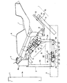
図1に示すように、操作装置は、このディスプレイ1の画面1aの前方に配置されている。この操作装置は、基本的な構成部材として、固定フレーム2、移動フレーム3、ハンドル4、支軸5、車体6、座席部7、およびステップ8を有する。操作装置はまた、これらの構成部材間の相対動作を規定する機構として、回動機構10、スライド機構20、および位置規制機構30を有する。以下にはまず、これらの要素の構成と配置関係の概略について説明する。
As shown in FIG. 1, the operating device is arranged in front of the screen 1 a of the display 1. This operating device has a fixed
図1に示すように、固定フレーム2は、ディスプレイ1の画面1aと対向するようにして床面上に水平配置されている。この固定フレーム2は、図2に示すように、ディスプレイ1の画面1aに向かって左右方向に伸びる前後一対の短辺と、ディスプレイ1の画面1aに向かって前後方向に伸びる左右一対の長辺とからなる長方形状に構成されている。そして、この固定フレーム2上の左右方向における中央部分には、画面1aと直交する方向に水平に伸びるようにして、車体6が配置されている。この車体6は、実際のオートバイの車体を模した形状とされている。また、図1に示すように、車体6のディスプレイ1と反対側の後方部分には、操作者が着座する座席部7が設けられ、車体6の座席部7よりも若干前方の下部には、操作者の足を乗せるステップ8が設けられている。
As shown in FIG. 1, the fixed
一方、図1に示すように、固定フレーム2上における車体6の前方部分の下方には、前後方向に伸びるようにして、移動フレーム3が配置されている。この移動フレーム3は、図2においては、上方の車体6によって覆われる形となるため、その前端部のみしか示されていないが、車体6と同様に、固定フレーム2上の左右方向における中央部分に、前後方向に伸びるようにして配置されている。すなわち、この移動フレーム3は、図2に示すような初期状態の垂直起立位置にある場合に、その中心軸が車体6の中心軸と垂直方向において重なるようにして配置されている。
On the other hand, as shown in FIG. 1, the moving
より詳細には、この移動フレーム3は、図1に示すように、五角形状に形成されている。すなわち、移動フレーム3は、固定フレーム2上に配置されて前後方向に伸びる下側水平部3aと、この下側水平部3aの前端部から垂直に立ち上げられた前方垂直部3bと、前方から後方に向かって下方に傾斜する傾斜部3cとを主要部分として構成されている。また、移動フレーム3の前方垂直部3bの上端部と傾斜部3cの前端部との間は、比較的短い上側水平部3dによって接続され、下側水平部3aの後端部と傾斜部3cの後端部との間は、比較的短い後方垂直部3eによって接続されている。
More specifically, the moving
さらに、図1に示すように、この移動フレーム3の上側水平部3dには、上方に突出するようにしてハンドル固定台4aが固定されており、このハンドル固定台4aには、図2に示すように、その中央部から左右斜め後方向に伸びるようにしてハンドル4が配置されている。また、移動フレーム3の傾斜部3cの上方には、この傾斜部3cと平行に支軸5が配置されており、この支軸5は、移動フレーム3に対して車体6を左右方向に回動自在に支持するように構成されている。なお、この支軸5は、移動フレーム3の傾斜部3cと同様に後方に向かって下方に傾斜しているが、その後端部は、固定フレーム2から離れた高い位置にあり、したがって、支軸5の全体が、床面より高い固定フレーム2から離れた高い位置に配置されている。そして、この支軸5と移動フレーム3の傾斜部3cを含む部分には、支軸5を中心として車体6を初期状態の垂直起立位置と左右方向における両側の傾斜位置との間で回動させる回動機構10が構成されている。
Further, as shown in FIG. 1, a
なお、図1に示すように、この移動フレーム3と固定フレーム2との間には、固定フレーム2に対して移動フレーム3を左右方向にスライドさせるスライド機構20が設けられている。また、固定フレーム2の後端部と車体6の座席部7下方との間には、固定フレーム2に対する車体6の左右方向における移動を (1−2)回動機構10の構成…図3、図4、図3は、回動機構10を示す側面図であり、図4は、回動機構10の主要部分を示す平面図(A)と断面図(B)である。図3に示すように、回動機構10は、移動フレーム3の傾斜部3cに対して支軸5を回動させ、この支軸5に支持された車体6を左右方向に回動させるための機構である。
As shown in FIG. 1, a
図3に示すように、移動フレーム3の傾斜部3cの両端部には、一対のピローブロック固定フレーム11が複数のボルト・ナット対11aによってそれぞれ固定され、各ピローブロック固定フレーム11上には、ピローブロック(軸受)12が複数のボルト・ナット対12aによってそれぞれ固定されている。そして、これらの一対のピローブロック12に支軸5が挿入され、回動自在に支持されている。
As shown in FIG. 3, a pair of pillow block fixing frames 11 are respectively fixed to both ends of the
一方、支軸5における両端小径部分の、ピローブロック12よりも中央側の部分には、マウントブロック13が一体的に接合されている。そして、この一対のマウントブロック13が、車体6側に固定されたブラケット14に取り付けられており、これによって、支軸5と車体6とが一体的に固定されている。
On the other hand, a
また、この支軸5のうち、ピローブロック12に挿入された両端部については、中央側よりも小径の円形断面とされているが、支軸5の中央の大径部分については、図4の(B)に示すように、矩形断面とされている。そして、この支軸5の矩形断面を有する中央大径部分の一部には、図4の(B)に示すように、4本の柱状の弾性材料からなる付勢手段15が、この支軸5を囲むようにして支軸5と平行に配置されている。この4本の付勢手段15は、この付勢手段15全体の外周を囲むようにして配置された固定部材16に接合されている。この固定部材16は、複数のボルト・ナット対16aによって移動フレーム4の傾斜部3cの一部に固定されている。
Further, the both ends of the
(1−3)スライド機構20の構成…図1、図5、図6
図5は、スライド機構20を示す平面図であり、図6は、図5の側面図である。図1に示すように、このスライド機構20はまず、固定フレーム2上の前方に左右方向に伸びるようにして配置されたラック付きガイドレール21と、このラック付きガイドレール21の後方に、このラック付きガイドレール21と間隔を空けて平行に配置されたガイドレール22を有する。ここで、ラック付きガイドレール21とガイドレール22は、複数のボルト・ナット対21a,22aによって固定フレーム2に固定されている。
(1-3) Configuration of
5 is a plan view showing the
一方、図5に示すように、移動フレーム3の下側水平部3aの両端部には、これらのラック付きガイドレール21とガイドレール22に沿ってスライドする各一対のスライダ23,24が設けられている。これらのスライダ23,24は、図6に示すように、スライダ取付部材25,26を介してガイドレール3に取り付けられている。ここで、スライダ23,24は、ボルト23a,24aによってスライダ取付部材25,26の各々にそれぞれ固定されており、スライダ取付部材25,26は、移動フレーム3に接合されている。このうち、後方のスライダ取付部材26については、移動フレーム3の下側水平部3aと後方垂直部3eとの接合部を兼ねており、ボルト・ナット対26aが使用されている。
On the other hand, as shown in FIG. 5, at both ends of the lower
また、図6に示すように、移動フレーム3の下側水平部3aの上方には、電動モータ27が設けられており、モータ取付部材28を介してガイドレール3に一体的に固定されている。この電動モータ27は、下方に伸びるモータシャフト27aとその先端に取り付けられたピニオン27b、および取付フランジ27cを備えている。ここで、電動モータ27の取付フランジ27cは、図5に示すように、ボルト・ナット対28aによってモータ取付部材28に固定されており、モータ取付部材28は、移動フレーム3に接合されている。また、ピニオン27bは、ラック付きガイドレール21のラックに噛み合い、電動モータ27の回転に応じて回転することにより、ラック付きガイドレール21に沿って左右方向に移動するようになっている。すなわち、このようなピニオン27bのラック付きガイドレール21に対する動作に伴い、電動モータ27と固定された移動フレーム3が左右方向に移動するようになっている。なお、モータ取付部材28上には、電動モータ27と並べてこの電動モータ27を冷却するためのファンが設けられている。
As shown in FIG. 6, an
(1−4)位置規制機構30の構成…図1、図7、図8
図7は、位置規制機構30を示す平面図(A)および背面図(B)であり、図8は、図7の(A)の側面図である。図1に示すように、この位置規制機構30はまず、固定フレーム2上の後端部に後斜め上方に伸びるようにして固定された位置規制部材31と、車体6の座席部7下方の下端部に後方に伸びるようにして一体的に固定された延設部材32を有する。このうち、延設部材32は、前方の水平部分と、位置規制部材31と平行に伸びる後方の傾斜部分とから構成されている。そして、この後方の傾斜部分の後端部には、この延設部材32の傾斜部分および位置規制部材31と直交する斜め下方に伸びる移動軸33が取付けられている。
(1-4) Configuration of
7 is a plan view (A) and a rear view (B) showing the
この移動軸33は、位置規制部材31の後端部に沿って設けられたガイド部材34内に挿入され、このガイド部材34に沿ってスライド自在に構成されている。この場合、図1に示すように、位置規制部材31、延設部材32、および移動軸33と支軸5との間には次のような配置関係がある。すなわち、移動軸33は支軸5と平行に配置され、位置規制部材31および延設部材32の傾斜部分は支軸5と直交する方向に配置されている。
The moving
より詳細には、図7の(A)に示すように、延設部材32は、上方の板状部材32aと下方のフレーム状部材32bを接合して構成されており、移動軸33は、延設部材32の後方の傾斜部分の左右方向における中央部に配置されている。また、位置規制部材31の後端部の内部には、図7の(B)に示すように一対のガイド部材34が挿入され、ガイド固定用金具34aによって位置規制部材31に固定されている。この一対のガイド部材34の相互間には、移動軸33の径にほぼ一致するガイド溝34bが形成され、このガイド溝34b内に移動軸33が挿入されるようになっている。さらに、位置規制部材31におけるガイド部材34の挿入部分には、移動軸33を挿入するための窓31aが設けられており、この窓31aの幅寸法は、移動軸33の径よりも大きくなっている。
More specifically, as shown in FIG. 7A, the extending
(2)作用および効果以上のような構成を有する本操作装置は、前述したような4つの特徴(1)〜(2)の全てを実現することができるものであり、さらに、(5)装置全体の小型・簡略化が果たされている。 (2) Operation and effect The operation device having the above-described configuration can realize all of the four characteristics (1) to (2) as described above, and (5) device. The overall size and simplification has been achieved.
(1)ステップに足を乗せた状態での操作性の確保
本操作装置においては、ハンドル4が移動フレーム3に固定されていることから、車体6のみが、回動機構10によって支軸5を中心として左右方向に傾斜する。また、操作者は、このハンドル4をつかむことで体勢の支持を移動フレーム3に依存することができるため、床面や固定フレーム2から足を離してステップ8に足を乗せ、車体6にほとんど全体重を預けても、ハンドル4を頼りに車体を引き起こすことが容易にできる。そして、車体6が左右方向に傾斜した場合に、操作者は、ハンドル4をつかんで体勢を支持することにより、ステップ8に足を乗せた状態のまま、車体6を垂直起立位置に引き起こすことができる。したがって、操作者が床面から足を離した状態で車体6を傾斜させても、車体6を垂直起立位置に復帰させることが可能となり、現実のオートバイの運転時に近い操作感覚を得ることができる。
(1) Ensuring operability with the foot on the step In the present operating device, since the
(2)ディスプレイに対する操作者の頭部位置の維持
本操作装置においては、車体6の回動の中心となる支軸5を、床面や固定フレーム2の高さに配置するのではなく、ステップ8よりもさらに高い位置に配置しているため、車体6の回動半径が小さくなっている。その上、この支軸5をハンドル4側の前方から後方に向かって下方に傾斜させているため、ほぼ水平状態で配置された車体6の回動半径は、前方に向かって小さくなっている。
(2) Maintaining the position of the operator's head relative to the display In this operating device, the
そのため、車体6がこの支軸5を中心として左右方向に回動する場合に、車体6の前方部分の左右方向および上下方向への移動量は、後方の座席部7に比較して小さくなる。また、操作者は、車体6に乗車した状態において、車体6の座席部7からハンドル側である前方に向かって上体を傾けた姿勢となるが、このような乗車姿勢において、操作者の頭部は車体6の前方に位置することになる。その結果、車体6を左右方向に傾斜させた場合に、前方に位置する操作者の頭部の左右方向および上下方向への移動量が抑制され、操作者はディスプレイ1の画面1aを見易くなる。
Therefore, when the
さらに、本操作装置においては、ハンドル4および車体6を支持する移動フレーム3自体をスライド機構20により固定フレーム2に対して左右方向にスライドさせることができる。そのため、車体6に体重を掛けて支軸5を中心として左右方向の片側に傾斜させた場合に、車体6に加わる荷重が、支軸5を介して移動フレーム3を傾斜側と反対側に移動させるように作用する。したがって、操作者が上体を大きく傾斜させた場合でも、実際の横方向の移動を小さくすることができ、操作者はディスプレイ1の画面1aをより見易くなる。
Furthermore, in this operating device, the moving
(3)現実に近い車体姿勢の確保
本操作装置においては、ハンドル4と車体6とが分離して設けられており、しかも車体6の回動中心である支軸5が傾斜しているため、車体6を傾斜させた場合には、現実のオートバイがカーブを曲がる際におけるハンドル4と車体6の屈曲角度、あるいは路面に対する車体6の傾斜に近い感覚を得ることができる。すなわち、車体6の回動中心の支軸が傾斜しているため、水平方向の力(トルク)によって車体6を立て直すことが可能であり、この点で現実のバイクの操縦感覚により近付く。例えば、車体を右に傾斜させた場合には、操作者の右腕が大きく曲ると同時に左腕が前方に伸び、この状態から車体を立て直す場合には、右腕を前方に伸ばす感覚で右側ハンドルグリップを押すと同時に、左腕で左側ハンドルグリップを引き寄せる動作を行うことにより、車体を立て直すことが可能である。このようなハンドルグリップの押し出し・引き寄せ動作は、現実のオートバイの操作感覚に非常に近似している。
(3) Ensuring vehicle body posture close to reality In this operating device, the
また、本操作装置においては、前述したように、車体6に体重を掛けて支軸5を中心として左右方向の片側に傾斜させた場合に、車体6に加わる荷重が、支軸5を介して移動フレーム3を傾斜側と反対側に移動させるように作用する。すなわち、車体6の左右方向の傾斜に対応してこの車体6を左右方向にスライドさせることができる。その結果、単に車体6を傾斜させるだけでなく、現実のオートバイの運転時に生じる横方向のズレの感覚を、操作時に得ることができる。
In the operating device, as described above, when a weight is applied to the
さらに、本操作装置においては、車体6の座席部7下方が、位置規制機構30によって左右方向における移動範囲を規制される一方で、車体6の座席部7よりも前方の部分は、スライド機構20によって移動フレーム3と共に左右方向に移動可能になっている。そのため、操作者が車体6に体重を掛けて支軸5を中心として左右方向の片側に傾斜させた場合には、車体6の座席部7下方に比べて前方の部分が傾斜側と反対側に大きく移動する。
Furthermore, in this operating device, the lower part of the seat part 7 of the
この場合、図9に示すように、車体6の座席部7下方に設けられた移動軸33が、ガイド部材34のガイド溝34bによって左右方向への移動を規制されているため、車体6は、座席部よりも前方部分の左右方向への移動に応じて、この移動軸33を中心として水平方向に回動し、初期状態の方向に対して水平方向における斜め前方向を向く形となる。この場合、車体6は、斜め前方に倒れ込むように傾斜する形となる。このような車体6の傾斜動作は、現実のオートバイがカーブを曲がる際の車体の動作ときわめてよく似ている。
In this case, as shown in FIG. 9, the
(4)現実に近いリアクションの確保
本操作装置においては、スライド機構20に電動モータ27を使用しているため、操作者が車体6の傾斜方向に体重を掛けない場合でも、この電動モータ27の駆動力により、ピニオン27bが回転し、このピニオン27bはラック付きガイドレール21のラックに対して左右方向に移動する。そして、このピニオン27bの動作により、このピニオン27bおよび電動モータ27を一体的に固定した移動フレーム3を固定フレーム2に対して左右方向に移動させることができる。その結果、電動モータ27の左右方向の駆動力を移動フレーム3を介して車体6に伝達することができる。例えば、この電動モータ27をディスプレイ1上に画像を投影するコンピュータによって制御することにより、画像の内容に対応した振動、衝撃、荷重、旋回中の車体6を引き起こすように作用する遠心力などのリアクションを車体6に発生させることができる。
(4) Ensuring reaction close to reality In this operating device, since the
また、以上のようなピニオン27bとラックの組み合わせにおいては、両者の寸法を適切に設定することにより、小型の電動モータ27であっても、移動フレーム3、車体6および操作者すべての荷重を円滑に移動させることができる。
Further, in the combination of the
さらに、本操作装置においては、支軸5と移動フレーム3との間に付勢手段15を設けているため、操作者が車体6を左右方向に傾斜させた場合には、車体6が、付勢手段15によって常に垂直起立位置に復帰するように付勢される。すなわち、車体6が傾斜した場合には、車体6に固定された支軸5が回動する結果、支軸5の矩形断面の外周と筒状の付勢手段15の矩形断面の内周とが係合し、付勢手段15を支軸5と同方向に回動させようとする。しかし、付勢手段15の外周は固定部材16を介して移動フレーム3に対して固定されているので、付勢手段15の回動は阻止され、付勢手段15の有する変形限度内で支軸5は回動する。この場合、この変形した付勢手段15には元の状態に復元しようとする力が生じ、この弾性復元力が、支軸5を垂直起立位置に復帰させる付勢力として作用することになる。その結果、操作者は、車体6を傾斜させた場合に、現実のオートバイの運転時に車体を傾斜させてカーブを曲がる場合に車体から受けるリアクションと同様なリアクションを受けることができる。
Furthermore, in this operating device, since the biasing means 15 is provided between the
また、前述したように、車体6の前方部分が、移動軸33を中心として水平方向に回動し、車体6が初期状態の方向に対して水平方向における斜め前方向を向いた場合には、進行方向における車体6の寸法が短くなるが、このような進行方向における寸法の変位量は、図9に示すような移動軸33のガイド溝34bに沿った前方下方への移動によって吸収される。したがって、この位置規制機構30により、車体6の水平方向における回動動作を円滑に行うことができる。
Further, as described above, when the front portion of the
(5)構成の小型・簡略化
本操作装置においては、構成部材間の相対動作を規定する機構として、回動機構10、スライド機構20、および位置規制機構30を設けているが、いずれの機構についても、構成が簡略であり、装置全体の小型・簡略化が果たされている。
(5) Miniaturization and simplification of configuration In this operating device, the
例えば、回動機構10については、図1からも明らかなように、支軸5の周辺に、ピローブロック12やマウントブロック13、および付勢手段15を使用しただけの簡略な構成であり、特に、支軸5を垂直起立位置に復帰させるための付勢手段としては、支軸5の外周に筒状の付勢手段15を被せているだけであるため、付勢手段の取り付けスペースが少なくて済む。
For example, as is clear from FIG. 1, the
また、スライド機構20については、図1からも明らかなように、移動フレーム3の周辺のスペースを利用して、ラック付きガイドレール21,ガイドレール22、スライダ23,24などを設けただけの簡略な構成である。この場合、スライド用の駆動手段として、電動モータ27を使用しているが、この電動モータ27についても、移動フレーム3のフレーム内に形成される空きスペースを利用して配置されているため、装置の大型化につながるものではない。また、この電動モータ27は、車体6から離れた位置に配置されているため、操作上の障害となることもない。
Further, as apparent from FIG. 1, the
さらに、位置規制機構30については、車体6の座席部7下方を支持する構成となる位置規制部材31および延設部材32をそのまま利用しているため、極めて簡略な構成である。特に、位置規制機構30において、位置規制のための専用の構成は、移動軸33とガイド部材34のみであり、この点で、装置の小型・簡略化が果たされている。
Furthermore, the
他の実施の形態本発明は、前述した形態に限定されるものではなく、他にも多種多様の形態を実施することが可能であり、回動機構、スライド機構、位置規制機構などの具体的な構成は自由に変更可能である。例えば、回動機構の支軸や付勢手段の構成は自由に変更可能である。 Other Embodiments The present invention is not limited to the above-described embodiment, and various other forms can be implemented, and specific examples such as a rotation mechanism, a slide mechanism, and a position regulation mechanism can be used. The configuration can be freely changed. For example, the structure of the support shaft and the urging means of the rotation mechanism can be freely changed.
また、スライド機構の駆動手段の構成は自由に変更可能であり、シリンダや電動モータによって駆動されるリンク機構などのアクチュエータを使用して、その一端を固定フレーム2側に連結し、他端を移動フレーム3に連結するなどの構成が可能である。一方、回動機構に回動力を与えるための回動用の駆動手段を設けることも可能であり、この場合には、操作者が力を加えない場合でも、自由に車体6を復帰させ、あるいは傾斜させることができる。
In addition, the structure of the slide mechanism drive means can be freely changed. Using an actuator such as a link mechanism driven by a cylinder or an electric motor, one end is connected to the fixed
そして、この回動用の駆動手段を、ディスプレイ上に画像を投影するコンピュータによって制御すれば、画像の内容に対応したリアルなリアクションを車体に発生させることができる。さらに、このような回動用の駆動手段とスライド用の駆動手段との両方を設けて、これらを組み合わせ、同様にコンピュータによって制御すれば、相乗効果によって臨場感を増大できる。また、スライド機構や位置規制機構を設けずに、回動機構のみを設け、移動フレーム3に相当するフレーム部分を固定フレーム2上に固定する構成なども可能であり、その場合には、装置全体の一層の小型・簡略化を実現できる。
If this driving means for rotation is controlled by a computer that projects an image on a display, a realistic reaction corresponding to the content of the image can be generated in the vehicle body. Furthermore, if both the driving means for rotation and the driving means for sliding are provided, combined, and similarly controlled by a computer, the sense of reality can be increased by a synergistic effect. Further, it is possible to provide a structure in which only a rotating mechanism is provided without providing a slide mechanism or a position restricting mechanism, and a frame portion corresponding to the moving
1:ディスプレイ
1a:画面
2:固定フレーム
3:移動フレーム
3a:下側水平部
3b:前方垂直部
3c:傾斜部
3d:上側水平部
3e:後方垂直部
4:ハンドル
4a:ハンドル固定台
5:支軸
6:車体
7:座席部
8:ステップ
10:回動機構
11:ピローブロック固定フレーム
11a:ボルト・ナット対
12:ピローブロック
12a:ボルト・ナット対
13:マウントブロック
14:ブラケット
15:付勢手段
16:固定部材
16a:ボルト・ナット対
20:スライド機構
21:ラック付きガイドレール
21a:ボルト・ナット対
22:ガイドレール
22a:ボルト・ナット対
23,24:スライダ
23a,24a:ボルト
25,26:スライダ取付部材
25a,26a:ボルト・ナット対
27:電動モータ
27a:モータシャフト
27b:取付フランジ
28:モータ取付部材
28a:ボルト・ナット対
30:位置規制機構
31:位置規制部材
31a:窓
32:延設部材
32a:板状部材
32b:フレーム状部材
33:移動軸
34:ガイド部材
34a:ガイド固定用金具
34b:ガイド溝
1: Display 1a: Screen 2: Fixed frame 3: Moving
Claims (2)
床面に水平配置される水平フレームと、該水平フレーム上に垂直に固定された垂直フレームとを有し、前記ディスプレイの画面前方に配置される固定フレームと、
前記垂直フレームと支軸を介して連結して回動可能に支持され、座席部と、該座席部に座った遊戯者の足を乗せるステップとを有する車体と、
前記画面に向かって前記座席部に座った前記遊戯者の前方に配設され、さらに、前記垂直フレームに配置されたハンドルと、
前記ハンドルを握った前記遊戯者が前記ステップに足を乗せて前記座席部に座った状態で前記車体に荷重を加えると、前記水平フレームから垂直に起立した位置を初期位置として、前記初期位置と前記初期位置から前記支軸を中心に傾斜した傾斜位置との間で、前記垂直フレームに対して前記車体を回動させる回動機構と、
前記回動機構により傾斜した前記傾斜位置に存在する前記車体を、前記遊戯者が前記ハンドルをつかんで引き起こす方向に力を付与して、前記車体を前記傾斜位置から前記初期位置に復帰させる付勢手段と、
を備え、
前記垂直フレームは、前記車体の下方に設けられ、前記座席部に対して傾斜する傾斜部を有しており、
前記傾斜部は、前記ハンドルが配置される位置から前記座席部の位置へ向かう方向に低くなるように傾斜しており、
前記支軸は、前記ハンドルの配置から前記座席部の位置へ向かう方向を軸方向とし、前記傾斜部に平行に配設した構成である、
ことを特徴とするゲーム装置。 A display device having a screen for displaying a game image generated by a computer;
A horizontal frame horizontally disposed on the floor, and a vertical frame vertically fixed on the horizontal frame, and a fixed frame disposed in front of the screen of the display;
A vehicle body connected to the vertical frame via a support shaft and rotatably supported, and having a seat portion and a step of placing a player's foot sitting on the seat portion,
Disposed in front of the player sitting on the seat portion toward the screen, and the handle further disposed on the vertical frame,
When the player who holds the handle puts his foot on the step and applies a load to the vehicle body while sitting on the seat, the initial position is defined as a position standing vertically from the horizontal frame. A rotation mechanism for rotating the vehicle body with respect to the vertical frame between the initial position and an inclined position inclined about the support shaft;
Energizing the vehicle body existing at the inclined position inclined by the rotation mechanism in a direction in which the player grabs the handle and causes the vehicle body to return from the inclined position to the initial position. Means,
With
The vertical frame is provided below the vehicle body and has an inclined portion inclined with respect to the seat portion,
The inclined portion is inclined so as to be lowered in a direction from the position where the handle is disposed toward the position of the seat portion,
The support shaft has a configuration in which a direction from the arrangement of the handle toward the position of the seat portion is an axial direction and is arranged in parallel to the inclined portion.
A game device characterized by that.
前記車体が傾斜すると前記支軸が回動し、前記固定部材の内側において前記支軸の一部が前記弾性材料と係合して当該弾性材料が弾性変形し、変形によって生じた前記弾性材料の弾性力により前記車体を前記初期位置に復帰させるように構成されてなる、請求項1に記載のゲーム装置。 The urging means is composed of four columnar elastic materials arranged in parallel so as to surround the support shaft as a center, and a fixing member arranged so as to surround the outer periphery of the four elastic materials,
When the vehicle body tilts, the support shaft rotates, and a part of the support shaft engages with the elastic material inside the fixed member, and the elastic material is elastically deformed. The game apparatus according to claim 1, wherein the game apparatus is configured to return the vehicle body to the initial position by an elastic force .
Priority Applications (1)
| Application Number | Priority Date | Filing Date | Title |
|---|---|---|---|
| JP2006191566A JP4296515B2 (en) | 2006-07-12 | 2006-07-12 | Operation device for motorcycle game machine |
Applications Claiming Priority (1)
| Application Number | Priority Date | Filing Date | Title |
|---|---|---|---|
| JP2006191566A JP4296515B2 (en) | 2006-07-12 | 2006-07-12 | Operation device for motorcycle game machine |
Related Parent Applications (1)
| Application Number | Title | Priority Date | Filing Date |
|---|---|---|---|
| JP23098095A Division JP4158126B2 (en) | 1995-09-08 | 1995-09-08 | Operation device for motorcycle game machine |
Publications (3)
| Publication Number | Publication Date |
|---|---|
| JP2006272007A JP2006272007A (en) | 2006-10-12 |
| JP2006272007A5 JP2006272007A5 (en) | 2006-12-07 |
| JP4296515B2 true JP4296515B2 (en) | 2009-07-15 |
Family
ID=37207271
Family Applications (1)
| Application Number | Title | Priority Date | Filing Date |
|---|---|---|---|
| JP2006191566A Expired - Fee Related JP4296515B2 (en) | 2006-07-12 | 2006-07-12 | Operation device for motorcycle game machine |
Country Status (1)
| Country | Link |
|---|---|
| JP (1) | JP4296515B2 (en) |
Families Citing this family (3)
| Publication number | Priority date | Publication date | Assignee | Title |
|---|---|---|---|---|
| KR20180047469A (en) * | 2016-10-31 | 2018-05-10 | (주)동호전자 | Game Simulator |
| KR20180047466A (en) * | 2016-10-31 | 2018-05-10 | (주)동호전자 | Motorcycle simulation game system |
| CN115721927A (en) * | 2021-08-31 | 2023-03-03 | 鸿富锦精密电子(烟台)有限公司 | Controller structure |
-
2006
- 2006-07-12 JP JP2006191566A patent/JP4296515B2/en not_active Expired - Fee Related
Also Published As
| Publication number | Publication date |
|---|---|
| JP2006272007A (en) | 2006-10-12 |
Similar Documents
| Publication | Publication Date | Title |
|---|---|---|
| JP4158126B2 (en) | Operation device for motorcycle game machine | |
| US6059666A (en) | Riding game system | |
| JP2945884B2 (en) | Experience drive device | |
| JP2015513123A (en) | Motion simulator | |
| US6234800B1 (en) | Simulator | |
| JPH1049035A (en) | Sheet supporting device of simulation device | |
| JP4296515B2 (en) | Operation device for motorcycle game machine | |
| US6210165B1 (en) | Operating device for motorcycle simulation apparatus | |
| US6008797A (en) | Stable foot pedal assembly | |
| JPH07199789A (en) | Game device | |
| JP3561071B2 (en) | Weight shift type steering apparatus and game apparatus using the same | |
| KR101900344B1 (en) | simulation simulator | |
| JP4349537B2 (en) | Simulator | |
| JP5688802B2 (en) | Riding simulator | |
| JPH0876678A (en) | Driving device for boarding section of simulator | |
| JP3048277B2 (en) | Image display game machine | |
| JP2920403B2 (en) | Drive game machine | |
| MXPA97003320A (en) | Device of handling for apparatus that simulate motorcycle | |
| JPH08215429A (en) | Physically sensing device for acceleration | |
| TWI796669B (en) | rocking device | |
| JP3917248B2 (en) | Amusement vehicle equipment | |
| JP2022074987A (en) | Rocking device and driving simulator | |
| TW202403693A (en) | System for simulating force sensation of driving | |
| JP2020203629A (en) | Lean type vehicle and vehicular lean unit | |
| TW202312112A (en) | Motion simulator |
Legal Events
| Date | Code | Title | Description |
|---|---|---|---|
| A621 | Written request for application examination |
Free format text: JAPANESE INTERMEDIATE CODE: A621 Effective date: 20060811 |
|
| A521 | Written amendment |
Free format text: JAPANESE INTERMEDIATE CODE: A523 Effective date: 20061020 |
|
| A131 | Notification of reasons for refusal |
Free format text: JAPANESE INTERMEDIATE CODE: A131 Effective date: 20070806 |
|
| A521 | Written amendment |
Free format text: JAPANESE INTERMEDIATE CODE: A523 Effective date: 20071005 |
|
| TRDD | Decision of grant or rejection written | ||
| A01 | Written decision to grant a patent or to grant a registration (utility model) |
Free format text: JAPANESE INTERMEDIATE CODE: A01 Effective date: 20090319 |
|
| A01 | Written decision to grant a patent or to grant a registration (utility model) |
Free format text: JAPANESE INTERMEDIATE CODE: A01 |
|
| A61 | First payment of annual fees (during grant procedure) |
Free format text: JAPANESE INTERMEDIATE CODE: A61 Effective date: 20090401 |
|
| R150 | Certificate of patent or registration of utility model |
Free format text: JAPANESE INTERMEDIATE CODE: R150 |
|
| FPAY | Renewal fee payment (event date is renewal date of database) |
Free format text: PAYMENT UNTIL: 20120424 Year of fee payment: 3 |
|
| FPAY | Renewal fee payment (event date is renewal date of database) |
Free format text: PAYMENT UNTIL: 20120424 Year of fee payment: 3 |
|
| FPAY | Renewal fee payment (event date is renewal date of database) |
Free format text: PAYMENT UNTIL: 20120424 Year of fee payment: 3 |
|
| FPAY | Renewal fee payment (event date is renewal date of database) |
Free format text: PAYMENT UNTIL: 20130424 Year of fee payment: 4 |
|
| FPAY | Renewal fee payment (event date is renewal date of database) |
Free format text: PAYMENT UNTIL: 20130424 Year of fee payment: 4 |
|
| LAPS | Cancellation because of no payment of annual fees |