JP4295593B2 - Car driving status indicator - Google Patents
Car driving status indicator Download PDFInfo
- Publication number
- JP4295593B2 JP4295593B2 JP2003350706A JP2003350706A JP4295593B2 JP 4295593 B2 JP4295593 B2 JP 4295593B2 JP 2003350706 A JP2003350706 A JP 2003350706A JP 2003350706 A JP2003350706 A JP 2003350706A JP 4295593 B2 JP4295593 B2 JP 4295593B2
- Authority
- JP
- Japan
- Prior art keywords
- lamp
- accelerator
- light
- brake
- pedal
- Prior art date
- Legal status (The legal status is an assumption and is not a legal conclusion. Google has not performed a legal analysis and makes no representation as to the accuracy of the status listed.)
- Expired - Fee Related
Links
Images


Landscapes
- Lighting Device Outwards From Vehicle And Optical Signal (AREA)
Description
本発明は、二輪や四輪の自動車における運転状況を他の自動車の運転者や歩行者などに認識させるための表示灯に関するものである。 The present invention relates to an indicator lamp for causing a driver or a pedestrian of another vehicle to recognize a driving situation in a two-wheel or four-wheel vehicle.
交通事故の多くは交差点などにおける自動車同士の事故や、道路横断中の歩行者の事故であり、例えば実際には止まる意志がないのに止まってくれるものと運転手や歩行者が対向してくる自動車の運転状況と異なる判断をしたことに起因するものが少なくない。 Many traffic accidents are accidents between cars at intersections, etc., and pedestrians while crossing the road. For example, drivers and pedestrians face things that stop without actually intending to stop. There are many things that result from making a judgment different from the driving situation of the car.
即ち、事故の多くは運転者や歩行者が停止してくれるものと自身が勝手に誤って判断したことによるものが少なくない。 In other words, many of the accidents are caused by mistakes that the driver or pedestrian stops.
そこで、車体の前方に運転状況を表示する表示灯を前方に備えた自動車が実公平6−36983号公報に提示されている。 Therefore, Japanese Utility Model Publication No. 6-36983 discloses an automobile equipped with an indicator lamp in front of the vehicle body for displaying the driving situation.
前記公報に提示されている運転状況表示灯は、それぞれ別体に形成されたブレーキランプとアクセルランプとからなり、ブレーキペダルを踏むとブレーキランプが点灯し、アクセルペダルを踏むとアクセルランプが点灯することにより、前方に位置する他の車両の運転者や歩行者に運転状況を知らせるものであり、運転状況をそのまま知らせることができる。 The driving status indicator lamps presented in the above publication are composed of a brake lamp and an accelerator lamp, which are formed separately. The brake lamp lights when the brake pedal is depressed, and the accelerator lamp lights when the accelerator pedal is depressed. By this, it notifies a driving condition to the driver and pedestrian of the other vehicle located ahead, and can notify a driving condition as it is.
しかしながら、前記公報に提示されている車体の前方に備えられた運転状況表示灯は、車体前部に設けられた運転状況表示灯が、ブレーキランプとアクセルランプとがそれぞれ別体に設けられている。そのため、運転者が例えばアクセルペタルを離してブレーキペダルを踏んだ際に、点灯していたアクセルランプが消灯してブレーキペダルが点灯するが、運転状況を他の運転者や歩行者は点灯していたアクセルランプから、アクセルランプに代わって点灯したブレーキペダルに視点を移して視認する必要があり、視認性に難点がある。特に、自動車は高速で走行するので視認の遅れが事故に結びつくことになる。 However, the driving status indicator lamp provided in front of the vehicle body disclosed in the above publication is the driving status indicator lamp provided at the front of the vehicle body, and the brake lamp and the accelerator lamp are provided separately. . For this reason, for example, when the driver releases the accelerator petal and steps on the brake pedal, the lit accelerator lamp goes off and the brake pedal lights, but the driving situation is lit by other drivers and pedestrians. It is necessary to change the viewpoint from the accelerator lamp to a brake pedal that is lit instead of the accelerator lamp, and there is a difficulty in visibility. In particular, automobiles run at high speeds, so visual delays can lead to accidents.
また、前記公報に提示されている車体の前方に備えられた運転状況表示灯は、アクセルペタルもブレーキペダルも操作していないときにはブレーキランプおよびアクセルランプの双方ともに消灯状態である。そのため、自動車がそのまま進んでくるのかその後にブレーキを踏んで停止するのかが他の運転者や歩行者にとっては判断できず、きわめて危険な状況を形成することになる。
本発明は、従来、知られている車体の前方に備えられた運転状況表示灯は、ブレーキランプとアクセルランプとがそれぞれ別体に設けられているので、他の運転者や歩行者が運転状況を視認しにくい、という前記課題を解決するためになされたものであり、他の運転者や歩行者に自動車の運転状況を確実に視認することが可能な運転状況表示灯を提供することを目的とする。 According to the present invention, in the conventional driving status indicator lamp provided in front of the vehicle body, the brake lamp and the accelerator lamp are provided separately from each other. In order to solve the above-mentioned problem that it is difficult to visually recognize the vehicle, it is an object to provide a driving status indicator capable of reliably viewing the driving status of the vehicle to other drivers and pedestrians. And
本発明は、前記課題を解決するために、発光表示部を前方に向けて車体に配置される自動車の運転状況表示灯であって、アクセルペダルを踏んでいるときに点灯または点滅するアクセルランプとブレーキペダルを踏んでいるときに点灯または点滅する前記アクセルランプと異なる色彩で発光するブレーキランプとが同一の発光表示部に一体的に配設した。 In order to solve the above-mentioned problems, the present invention provides a driving status display lamp for an automobile disposed on a vehicle body with a light emitting display portion facing forward, and an accelerator lamp that lights or blinks when an accelerator pedal is depressed, The accelerator lamp that lights up or flashes when the brake pedal is depressed and the brake lamp that emits light in a different color are integrally disposed on the same light emitting display portion.
また、アクセルペダルまたはブレーキペダルの一方を踏んでいないときに点灯または点滅する前記アクセルランプおよびブレーキペダルと異なる色彩で発光させ、更に、発光表示部に一体的に配設されているアクセルランプ、ブレーキランプおよび走行ランプが発光したときに互いに異なる所定の形状に発光させる。 In addition, the accelerator lamp and the brake pedal that are lit or blinking when one of the accelerator pedal and the brake pedal is not depressed are emitted in a color different from that of the accelerator lamp and the brake pedal. When the lamp and the running lamp emit light, they are emitted in different predetermined shapes.
それぞれ異なる色彩で発光または点滅するブレーキランプとアクセルランプとを同一の発光表示部に一体的に配設することにより、他の運転者や歩行者は発光表示部に視線を注いでいれば、視認箇所を変更することなしに運転状況の変化を容易且つ確実に確認することができる。 By arranging the brake lamp and accelerator lamp, which emit or flash in different colors, in the same light-emitting display unit, other drivers and pedestrians can see if they are looking at the light-emitting display unit. It is possible to easily and reliably confirm changes in the driving situation without changing the location.
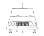
図1乃至図3は本発明を実施するための最良の形態の一例を示すものであり、運転状況表示灯1は図1に示すように例えば横長の矩形を呈する板状で、自動車の車体2の前方に配置されている。
FIG. 1 to FIG. 3 show an example of the best mode for carrying out the present invention. The driving
前記運転状況表示灯1は、図2に示すように、ブレーキペダルとアクセルペダルの双方ともに踏んでいない状態を発光表示するための青色発光ダイオードからなる走行ランプ12,ブレーキペダルを踏んでいる状態を発光表示するための赤色発光ダイオードからなるブレーキランプ13,アクセルランプを踏んでいる状態を発光表示するための緑色発光ダイオードからなるアクセルランプ14からなる発光ダイオードユニット11(以下「LEDユニット」という)の複数個のほぼ全面に配置された集合体により形成される。
As shown in FIG. 2, the driving
また、図3は前記LEDユニット11の制御回路の概略を示すものであり、制御回路20は、主としてバッテリ21、エンジンのキースイッチを兼ねる電源スイッチ22、LEDユニット11に接続される切換スイッチ23などから構成され、切換スイッチ23はアクセルペダルとブレーキペダルに配置したスイッチ(図示せず)に接続されている。
FIG. 3 shows an outline of the control circuit of the
そして、キースイッチを兼ねる電源スイッチ22をオン状態としたときには運転状況表示灯1に配置されたLEDユニット11の内、青色発光ダイオードに電流が流れ走行ランプ12が発光し、LEDユニット11が青色を表示す
When the
その後、アクセルペダルを踏んで車体2を発進させると、アクセルペダルに配置したスイッチからの信号が切換スイッチ23を制御して発光していた走行ランプ(青色発光ダイオード)12への電流を遮断し、代わりにアクセルランプ(緑色発光ダイオード)14に電流が流れ、LEDユニット11が緑色を表示する。
Thereafter, when the
そして、走行中に、アクセルペダルから足を離すと発光していたアクセルランプ(緑色発光ダイオード)14への電流を遮断し、代わりに走行ランプ(青色発光ダイオード)12に電流が流れ走行ランプ(青色発光ダイオード)12を発光させ、ブレーキペダルを踏んだときには走行ランプ(青色発光ダイオード)12が消灯し、代わってブレーキランプ(赤色発光ダイオード)13に電流が流れ、LEDユニット11が赤色を表示する。
Then, during traveling, the current to the accelerator lamp (green light emitting diode) 14 that was emitted when the foot is released from the accelerator pedal is cut off. Instead, the current flows to the traveling lamp (blue light emitting diode) 12 and the traveling lamp (blue light emitting diode). When the brake pedal is depressed, the travel lamp (blue light-emitting diode) 12 is turned off. Instead, a current flows through the brake lamp (red light-emitting diode) 13, and the
従って、運転状況表示灯1が自動車の運転状況に従って予め定めた運転状況の色彩に発光するので、他の運転者や歩行者に視認される。特に、本実施の形態では、LEDユニット11全体が光るので視認しやすいばかりか、同一のLEDユニット11の発光の色が運転状況に従って変化するので視認が容易且つ確実である。
Therefore, since the driving
以上の実施の形態によれば、運転状況を自動車の前面に配置した運転状況表示灯1に発光表示することになるので、交差点や横断歩道などを通過しようとする他の自動車の運転手や歩行者は、運転状況表示灯1が緑色に発光している場合にはアクセルペダルを踏んでいるものと、また、運転状況表示灯1が赤色に発光している場合にはブレーキペダルを踏んでいるものと、更に、運転状況表示灯1が青色に発光している場合にはアクセルペダルおよびブレーキペダルの双方を踏んでいないものと判断することができるので、従来のように単に自動車の自己の判断で自動車を合流、右折させたり、道路を横断したりすることとがなく、事故の発生を有効に防止することができる。
According to the above embodiment, since the driving status is displayed on the driving
尚、本実施の形態では、LEDユニット11は横長の矩形を呈する板状で、そのほぼ全面に走行ランプ(青色発光ダイオード)12,ブレーキランプ(赤色発光ダイオード)13,アクセルランプ(緑色発光ダイオード)14が縦および横方向に並設されている構成としたので、矩形形のLEDユニット11全体が均一に光るのできわめて視認性がよいが、LEDユニット11に例えばブレーキペダルを踏んでいるときに発光するブレーキランプ(赤色発光ダイオード)13を平面X形に(図4参照)、アクセルペダルを踏んでいるときに発光するアクセルランプ(緑色発光ダイオード)14を平面O形に(図5参照)それぞれ配置しておくと、他の運転者や歩行者は単に特定の色彩による発光の変化だけでなく特定の形状の変化も併せて確認できるので更に視認性がよくなる
In the present embodiment, the
また、本実施の形態では、運転状況表示灯1は、ブレーキペダルとアクセルペダルの双方ともに踏んでいない状態を青色に、ブレーキペダルを踏んでいる状態を赤色に、アクセルペダルを踏んでいる状態を緑色で表示するようにしたが、これは、現在の交通信号などを参考にして定めたものであるが、これに限るものでなく、他の組み合わせまたは他の異なる種類の色彩を採用してもよく、各運転状況に従って点灯する光の変化とその運転状況が確実に伝わるものであればよい。
In the present embodiment, the driving
更に、本実施の形態では、運転状況表示灯1の光源として少ない電力で高い輝度を有する発光ダイオードを用いたので、耐久性、視認性、経済性に優れているという利点を有しているが、通常自動車の表示灯として用いられている電球を用いてもよいことはいうまでもない。
Furthermore, in this embodiment, since the light emitting diode having high luminance with low power is used as the light source of the driving
1 運転状況表示灯、2 車体、11 LEDユニット、12 走行ランプ、13 ブレーキランプ、14 アクセルランプ、20 制御回路、21 バッテリー、22 スイッチ、23 切換スイッチ
DESCRIPTION OF
Claims (2)
2. The driving status display lamp for an automobile according to claim 1 , wherein when the accelerator lamp, the brake lamp, and the traveling lamp that are integrally disposed on the light emitting display portion emit light, the light is emitted in a predetermined shape different from each other .
Priority Applications (1)
| Application Number | Priority Date | Filing Date | Title |
|---|---|---|---|
| JP2003350706A JP4295593B2 (en) | 2003-10-09 | 2003-10-09 | Car driving status indicator |
Applications Claiming Priority (1)
| Application Number | Priority Date | Filing Date | Title |
|---|---|---|---|
| JP2003350706A JP4295593B2 (en) | 2003-10-09 | 2003-10-09 | Car driving status indicator |
Publications (2)
| Publication Number | Publication Date |
|---|---|
| JP2005112227A JP2005112227A (en) | 2005-04-28 |
| JP4295593B2 true JP4295593B2 (en) | 2009-07-15 |
Family
ID=34542185
Family Applications (1)
| Application Number | Title | Priority Date | Filing Date |
|---|---|---|---|
| JP2003350706A Expired - Fee Related JP4295593B2 (en) | 2003-10-09 | 2003-10-09 | Car driving status indicator |
Country Status (1)
| Country | Link |
|---|---|
| JP (1) | JP4295593B2 (en) |
Families Citing this family (6)
| Publication number | Priority date | Publication date | Assignee | Title |
|---|---|---|---|---|
| JP4161083B1 (en) * | 2007-06-27 | 2008-10-08 | 株式会社ジェイ・エー・シー | Start indicator light system in sports competitions |
| JP4177887B1 (en) * | 2007-11-05 | 2008-11-05 | 株式会社ジェイ・エー・シー | Start indicator light system |
| KR101993104B1 (en) * | 2015-09-30 | 2019-09-30 | 닛산 지도우샤 가부시키가이샤 | Vehicle status display system |
| JP6225301B1 (en) * | 2016-06-13 | 2017-11-08 | 司 小笠原 | "Security confirmation light" system |
| JP7355378B2 (en) * | 2019-05-23 | 2023-10-03 | 學 鈴木 | Brake status display device |
| CN112238807A (en) * | 2019-07-19 | 2021-01-19 | 许永明 | Locomotive throttle indicator lamp |
-
2003
- 2003-10-09 JP JP2003350706A patent/JP4295593B2/en not_active Expired - Fee Related
Also Published As
| Publication number | Publication date |
|---|---|
| JP2005112227A (en) | 2005-04-28 |
Similar Documents
| Publication | Publication Date | Title |
|---|---|---|
| US20140301101A1 (en) | Multifunctional Multiple Color Center High Mounted Stop Lamp | |
| WO2019156106A1 (en) | Automated driving display system and vehicle communication system | |
| CN108349428A (en) | Lighting Devices for Vehicles | |
| US20050099287A1 (en) | Indicator system for vehicles | |
| US10551024B2 (en) | Combination rear lamp | |
| CN1978244B (en) | Vehicle Lamps | |
| US20100177529A1 (en) | Automobile brake lamp | |
| JP6530497B2 (en) | Motorcycle and motorcycle light lighting device | |
| JP2005112227A (en) | Operation status indication lamp of automobile | |
| KR102695903B1 (en) | Lamp system for vehicle | |
| JP4615041B2 (en) | Auxiliary turn signal | |
| JP3124140U (en) | Car lighting system | |
| JP2003034179A (en) | Automobile | |
| KR200394195Y1 (en) | High Mounted Combination Lamp for Vehicle | |
| JP7456586B2 (en) | vehicle display system | |
| TWM608645U (en) | Controller of warning device | |
| TWM609114U (en) | Daytime running light structure for locomotive | |
| JPH11334464A (en) | Display device for automobile | |
| JP3125500U (en) | Automotive stop indicator light | |
| JP3219036U (en) | Vehicle blinker and hazard lamp interlock controller | |
| JPH1148860A (en) | Vehicle lighting system | |
| CN1799902A (en) | Vehicle Indicator System | |
| JP2010262889A (en) | Vehicle lamp | |
| JP3215978U (en) | Emergency stop display device | |
| KR20170001126U (en) | Vehicle taillights |
Legal Events
| Date | Code | Title | Description |
|---|---|---|---|
| A621 | Written request for application examination |
Free format text: JAPANESE INTERMEDIATE CODE: A621 Effective date: 20061006 |
|
| A977 | Report on retrieval |
Free format text: JAPANESE INTERMEDIATE CODE: A971007 Effective date: 20081211 |
|
| A131 | Notification of reasons for refusal |
Free format text: JAPANESE INTERMEDIATE CODE: A131 Effective date: 20090106 |
|
| A521 | Written amendment |
Free format text: JAPANESE INTERMEDIATE CODE: A523 Effective date: 20090303 |
|
| TRDD | Decision of grant or rejection written | ||
| A01 | Written decision to grant a patent or to grant a registration (utility model) |
Free format text: JAPANESE INTERMEDIATE CODE: A01 Effective date: 20090331 |
|
| A01 | Written decision to grant a patent or to grant a registration (utility model) |
Free format text: JAPANESE INTERMEDIATE CODE: A01 |
|
| A61 | First payment of annual fees (during grant procedure) |
Free format text: JAPANESE INTERMEDIATE CODE: A61 Effective date: 20090410 |
|
| FPAY | Renewal fee payment (prs date is renewal date of database) |
Free format text: PAYMENT UNTIL: 20120417 Year of fee payment: 3 |
|
| R150 | Certificate of patent (=grant) or registration of utility model |
Free format text: JAPANESE INTERMEDIATE CODE: R150 |
|
| LAPS | Cancellation because of no payment of annual fees |