JP4295465B2 - Image processing device - Google Patents
Image processing device Download PDFInfo
- Publication number
- JP4295465B2 JP4295465B2 JP2002070128A JP2002070128A JP4295465B2 JP 4295465 B2 JP4295465 B2 JP 4295465B2 JP 2002070128 A JP2002070128 A JP 2002070128A JP 2002070128 A JP2002070128 A JP 2002070128A JP 4295465 B2 JP4295465 B2 JP 4295465B2
- Authority
- JP
- Japan
- Prior art keywords
- image data
- color space
- image
- image processing
- gradations
- Prior art date
- Legal status (The legal status is an assumption and is not a legal conclusion. Google has not performed a legal analysis and makes no representation as to the accuracy of the status listed.)
- Expired - Fee Related
Links
Images


Description
【0001】
【発明の属する技術分野】
本発明は、画像ファイルに対して画像処理を施す画像処理装置および画像処理プログラムに関する。
【0002】
【従来の技術】
現在、様々な色空間に基づく画像データが、コンピュータ、プリンタ、ディジタルスチルカメラといった画像データの処理装置において用いられている。例えば、コンピュータでは、通常、モニタに出力することを前提としてRGB色空間に基づく画像データが用いられており、ディジタルスチルカメラ(DSC)では、生成した画像データをJPEG形式にて圧縮して保存するため、データ圧縮に適当なYCbCr色空間に基づく画像データが用いられている。したがって、例えば、DSCにて生成した画像データをコンピュータにて処理する際には、画像データの色空間を、YCbCr色空間からRGB色空間に変換する必要があった。
【0003】
【発明が解決しようとする課題】
しかしながら、画像データの色空間を第1の色空間(YCbCr)から第2の色空間(RGB)へ変換すると、第1の色空間では等間隔に並んでいた色彩値が、第2の色空間では必ずしも等間隔に並ばないことがあるため、変換後の画像データの階調数(表色数)が変換前の画像データの階調数(表色数)と比べて減少してしまうという問題があった。階調数が減少すると、再現することができる色数が減少するため、画像データの色彩を正確に表現することができず、階調飛びのある出力画像しか得られないという問題が発生する。
【0004】
本発明は、上記問題点を解決するためになされたものであり、画像処理変換の前後を通して画像データの階調数、表色数を維持することを目的とする。
【0005】
【課題を解決するための手段およびその作用・効果】
上記課題を解決するために本発明の第1の態様は、画像データに対して画像処理を実行する画像処理装置を提供する。本発明の第1の態様に係る画像処理装置は、第1の色座標系における表色系であって、第1の色数を表色可能な第1の表色系の画像データを、第2の色座標系における表色系であって、前記第1の色数よりも多い第2の色数を表色可能な第2の表色系の画像データへ、マトリクス演算により変換する色変換手段と、前記第2の表色系において前記変換された画像データに対して画像処理を実行する画像処理手段と、前記画像処理が施された画像データの表色数を低減させる表色数低減手段とを備えることを特徴とする。
【0006】
本発明の第1の態様に係る画像処理装置によれば、第1の色座標系における第1の色数を表色可能な第1の表色系の画像データを、第2の色座標系における第1の色数よりも多い第2の色数を表色可能な第2の表色系の画像データへ、マトリクス演算により変換することができるので、異なる色座標系間において色変換処理を実行した場合であっても色変換処理(画像処理)の前後を通して画像データの階調数、表色数を維持することができる。
【0007】
本発明の第1の態様に係る画像処理装置において、前記画像処理手段により実行される画像処理には、ガンマ補正処理が含まれても良く、第2のマトリクス演算を用いた色変換処理が含まれても良い。
【0008】
本発明の第1の態様に係る画像処理装置において、前記第1の表色系はYCC表色系であり、前記第2の表色系はsRGB表色系であっても良く、あるいは、前記第1の表色系はYCC表色系であり、前記第2の表色系はsRGB表色系よりも広い表色域を有するwRGB表色系であっても良い。いずれの場合にも色変換後も第1の色数は維持され、特に、wRGB表色系が用いられる場合には、sRGB表色系では表色されない負の色彩値についても表色することができる。
【0009】
本発明の第1の態様に係る画像処理装置において、前記第2の表色系の第2の色数には、前記色変換手段によって前記第1の表色系から前記第2の表色系に変換された画像データに含まれている負値によって表現される色数が含まれても良い。かかる場合には、第1の表色系から第2の表色系へと変換された画像データに負値が含まれている場合であっても、負値によって表現される色彩値を欠落することなく表色することができる。
【0010】
本発明の第2の態様は、画像データに対して画像処理を実行する画像処理装置を提供する。本発明の第1の態様に係る画像処理装置は、第1の有効数字を有する整数値で表される前記画像データの色彩値を、前記第1の有効数字の桁数よりも多い桁数を有する第1の値に変更する第1の画像処理手段と、前記第1の画像処理手段による色彩値の変更に伴う前記画像データの階調数の減少を防止する階調数減少防止手段と、前記第1の値を有する画像データの色彩値を前記第1の値から、画像出力結果に反映される第2の値に変更する第2の画像処理手段とを備えることを特徴とする。
【0011】
本発明の第2の態様に係る画像処理装置によれば、第1の値への色彩値の変更に伴う画像データの階調数の減少を防止し、第1の値を有する画像データの色彩値を第1の値から、画像出力結果に反映される第2の値に変更するので、画像処理変換の前後を通して画像データの階調数、表現色数を維持することができる。
【0012】
本発明の第2の態様に係る画像処理装置において、前記階調数減少防止手段は、前記第1の有効数字の桁数よりも多い桁数まで前記第1の値の有効数字を設定することにより、前記画像データの階調数の減少を防止しても良い。かかる場合には、異なる複数の第1の有効数字を有する整数値が同一の第1の値を取った場合であっても、有効数字の桁数が増加するので元の階調数を維持することができる。なお、前記階調数減少防止手段によって階調数の減少が防止された画像データのデータサイズは、前記第1の有効数字を有する整数値で表される画像データのデータサイズよりも大きくても良い。画像データの有効数字の桁数が増加するので、画像データのデータサイズは増加する。
【0013】
本発明の第2の態様に係る画像処理装置において、前記第1の画像処理手段は、前記画像データの色空間を第1の色空間から第2の色空間に変換する色空間変換手段であっても良い。また、前記色空間変換手段は、前記画像データの色空間をYCbCr色空間からRGB色空間へ変換し、前記第1の有効数字を有する整数値で表される前記画像データの色彩値を、小数点を含む前記第1の値に変更しても良い。有効数字の桁数を増加させることにより、第1の値が小数点を含む場合であっても、階調数を維持することができる。
【0014】
本発明の第3の態様は、画像データに対して画像処理を実行する画像処理装置を提供する。本発明の第3の態様に係る画像処理装置は、前記画像データの階調数を第1の階調数から第2の階調数に増加させると共に、画像データの色空間をYCbCr色空間からsRGB色空間に変換する第1の色空間変換手段と、前記色空間が変換された画像データに対してガンマ補正処理を実行するガンマ補正手段と、前記ガンマ補正処理が実行された画像データの色空間をsRGB色空間からsRGB色空間よりも広い定義領域を有するwRGB色空間に変換する第2の色空間変換手段と、前記色空間が変換された画像データの階調数を前記第2の階調数から前記第1の階調数に戻す階調数低減手段とを備えることを特徴とする。
【0015】
本発明の第3の態様に係る画像処理装置によれば、画像データの階調数を第1の階調数から第2の階調数に増加させつつ、画像データの色空間をYCbCr色空間からsRGB色空間に変換するので、画像処理変換の前後を通して画像データの階調数、表現色数を維持することができる。
【0016】
本発明の第3の態様に係る画像処理装置はさらに、
前記色空間が変換された画像データに対して逆ガンマ補正処理を実行する逆ガンマ補正手段を備え、
前記階調数低減手段は、前記色空間が変換された画像データに代えて、前記逆ガンマ補正が実行がされた画像データの階調数を前記第2の階調数から第1の階調数に戻しても良い。かかる場合には、逆ガンマ補正処理における階調精度を維持または向上させることができる。
【0017】
本発明の第3の態様に係る画像処理装置はさらに、
前記逆ガンマ補正が実行された画像データの画質を自動的に補正する画像補正手段を備え、
前記階調数低減手段は、前記逆ガンマ補正が実行がされた画像データに代えて、前記画質が補正された画像データの階調数を前記第2の階調数から第1の階調数に戻しても良い。かかる場合には、画像補正処理における階調精度を維持または向上させることができる。
【0018】
本発明の第4の態様は、画像処理の施された画像データを出力する出力装置を提供する。本発明の第4の態様に係る印刷装置は、本発明の第1〜第3の態様のいずれかに係る画像処理装置と、前記画像処理装置によって画像処理の施された画像データを出力する出力手段とを備えることを特徴とする。
【0019】
本発明の第4の態様に係る出力装置によれば、階調性の良い画像データを出力することができる。
【0020】
本発明の第5の態様は、画像データに対して画像処理を実行するための画像処理プログラムを提供する。本発明の第5の態様に係る画像処理プログラムは、第1の色座標系における表色系であって、第1の色数を表色可能な第1の表色系の画像データを、第2の色座標系における表色系であって、前記第1の色数よりも多い第2の色数を表色可能な第2の表色系の画像データへ、マトリクス演算により変換する機能と、前記第2の表色系において前記変換された画像データに対して画像処理を実行する機能と、前記画像処理が施された画像データの表色数を低減させる機能とをコンピュータによって実現させることを特徴とする。
その他:本手続補正書における補正は、「前記第1の色数を保持しつつ」を削除する補正であり、新規事項を導入するものではない。
【0021】
本発明の第5の態様に係る画像処理プログラムによれば、本発明の第1の態様に係る画像処理装置と同様の作用効果を得ることができる。また、本発明の第5の態様に係る画像処理プログラムは、本発明の第1の態様に係る画像処理装置と同様にして、種々の態様にて実現され得る。
【0022】
本発明の第6の態様は、画像データに対して画像処理を実行するための画像処理プログラムを提供する。本発明の第6の態様に係る画像処理プログラムは、第1の有効数字を有する整数値で表される前記画像データの色彩値を、前記第1の有効数字の桁数よりも多い桁数を有する第1の値に変更する第1の画像処理機能と、前記第1の画像処理手段による色彩値の変更に伴う前記画像データの階調数の減少を防止する機能と、前記第1の値を有する画像データの色彩値を前記第1の値から、画像出力結果に反映される第2の値に変更する第2の画像処理機能とをコンピュータによって実現させることを特徴とする。
【0023】
本発明の第6の態様に係る画像処理プログラムによれば、本発明の第2の態様に係る画像処理装置と同様の作用効果を得ることができる。また、本発明の第6の態様に係る画像処理プログラムは、本発明の第2の態様に係る画像処理装置と同様にして、種々の態様にて実現され得る。
【0024】
本発明の第7の態様は、画像データに対して画像処理を実行するための画像処理プログラムを提供する。本発明の第7の態様に係る画像処理プログラムは、前記画像データの階調数を第1の階調数から第2の階調数に増加させると共に、画像データの色空間をYCbCr色空間からsRGB色空間に変換する第1の色空間変換機能と、前記色空間が変換された画像データに対してガンマ補正処理を実行するガンマ補正機能と、前記ガンマ補正処理が実行された画像データの色空間をsRGB色空間からsRGB色空間よりも広い定義領域を有するwRGB色空間に変換する第2の色空間変換機能と、前記色空間が変換された画像データの階調数を前記第2の階調数から前記第1の階調数に戻す階調数低減機能とをコンピュータによって実現させることを特徴とする。
【0025】
本発明の第7の態様に係る画像処理プログラムによれば、本発明の第3の態様に係る画像処理装置と同様の作用効果を得ることができる。また、本発明の第7の態様に係る画像処理プログラムは、本発明の第3の態様に係る画像処理装置と同様にして、種々の態様にて実現され得る。
【0026】
【発明の実施の形態】
以下、本発明に係る画像処理装置について以下の順序にて図面を参照しつつ、いくつかの実施例に基づいて説明する。
A.画像処理システムの構成:
B.画像ファイル構造:
C.画像処理装置における画像処理:
D.その他の実施例:
【0027】
A.画像処理システムの構成:
本実施例に係る画像処理装置を適用可能な画像処理システムの構成について図1〜図4を参照して説明する。図1は本実施例に係る画像処理装置を適用可能な画像処理システムの一例を示す説明図である。図2は本実施例に係る画像処理装置が出力する画像ファイル(画像データ)を生成可能なディジタルスチルカメラの概略構成を示すブロック図である。図3は本実施例に適用され得るカラープリンタの内部構成を示す概略図である。図4はカラープリンタ20の制御回路の内部構成を示すブロック図である。
【0028】
画像処理システム10は、画像ファイルを生成する入力装置としてのディジタルスチルカメラ12、ディジタルスチルカメラ12にて生成された画像ファイルに基づいて画像処理を実行し、印刷用画像データを出力する画像処理装置としてのパーソナルコンピュータPC、印刷用画像データを出力する出力装置としてのカラープリンタ20を備えている。画像処理装置としては、パーソナルコンピュータPCの他に、例えば、スタンドアローン型のプリンタも用いられ得る。また、出力装置としては、プリンタ20の他に、CRTディスプレイ、LCDディスプレイ等のモニタ14、プロジェクタ等が用いられ得る。以下の説明では、パーソナルコンピュータPCと接続されて用いられるカラープリンタ20を出力装置として用いるものとする。
【0029】
パーソナルコンピュータPCは、一般的に用いられているタイプのコンピュータであり、本発明に係る画像処理プログラムを実行するCPU150、CPU150における演算結果、画像データ等を一時的に格納するRAM151、画像処理プログラムを格納するハードディスクドライブ(HDD)152を備えている。パーソナルコンピュータPCは、メモリカードMCを装着するためのカードスロット153、ディジタルスチルカメラ12等からの接続ケーブルを接続するための入出力端子154を備えている。
【0030】
ディジタルスチルカメラ12は、図2に示すように、光の情報をディジタルデバイス(CCDや光電子倍増管)に結像させることにより画像を取得するカメラであり、図2に示すように光情報を収集するためのCCD等を備える光学回路121、光学回路121を制御して画像を取得するための画像取得回路122、取得したディジタル画像を加工処理するための画像処理回路123、メモリを備えると共に各回路を制御する制御回路124を備えている。ディジタルスチルカメラ12は、取得した画像をディジタルデータとして記憶装置としてのメモリカードMCに保存する。ディジタルスチルカメラ12における画像データの保存形式としては、JPEG形式が一般的であるが、この他にもTIFF形式、GIF形式、BMP形式、RAWデータ形式等の保存形式が用いられ得る。
【0031】
ディジタルスチルカメラ12はまた、明度、コントラスト、露出補正量(露出補正値)、ホワイトバランス等の個別の画像処理制御パラメータ、および撮影条件に応じて予め複数の画像処理制御パラメータの値が設定されている撮影モードを設定するための選択・決定ボタン126、撮影画像をプレビューしたり、選択・決定ボタン126を用いて撮影モード等を設定するための液晶ディスプレイ127を備えている。
【0032】
本画像処理システム10に用いられるディジタルスチルカメラ12は、画像データGDに加えて画像データの画像処理制御情報GCを画像ファイルGFとしてメモリカードMCに格納する。すなわち、画像処理制御情報GCは、撮影時に画像データGDと共に自動的に画像ファイルGFを構成する情報としてメモリカードMCに自動的に格納される。
【0033】
ディジタルスチルカメラ12において生成された画像ファイルGFは、例えば、ケーブルCV、コンピュータPCを介して、あるいは、ケーブルCVを介してカラープリンタ20に送出される。あるいは、ディジタルスチルカメラ12にて画像ファイルGFが格納されたメモリカードMCが、メモリカード・スロットに装着されたコンピュータPCを介して、あるいは、メモリカードMCをプリンタ20に対して直接、接続することによって画像ファイルがカラープリンタ20に送出される。なお、以下の説明では、メモリカードMCがパーソナルコンピュータPCに対して直接、接続される場合に基づいて説明する。
【0034】
図3を参照して本実施例に用いられる画像出力装置、すなわち、カラープリンタ20の内部構成について説明する。カラープリンタ20は、カラー画像の出力が可能なプリンタであり、例えば、シアン(C)、マゼンタ(M)、イエロー(Y)、ブラック(K)の4色の色インクを印刷媒体上に噴射してドットパターンを形成することによって画像を形成するインクジェット方式のプリンタである。あるいは、カラートナーを印刷媒体上に転写・定着させて画像を形成する電子写真方式のプリンタである。色インクには、上記4色に加えて、ライトシアン(薄いシアン、LC)、ライトマゼンタ(薄いマゼンタ、LM)、ダークイエロ(暗いイエロ、DY)を用いても良い。
【0035】
カラープリンタ20は、図示するように、キャリッジ30に搭載された印字ヘッドIH1〜IH4を駆動してインクの吐出およびドット形成を行う機構と、このキャリッジ30をキャリッジモータ31によってプラテン32の軸方向に往復動させる機構と、紙送りモータ33によって印刷用のカット紙40を搬送する機構と、制御回路50とから構成されている。キャリッジ30をプラテン32の軸方向に往復動させる機構は、プラテン32の軸と並行に架設されたキャリッジ30を摺動可能に保持する摺動軸34と、キャリッジモータ31との間に無端の駆動ベルト35を張設するプーリ36等から構成されている。
【0036】
制御回路50は、プリンタの操作パネル21と信号をやり取りしつつ、紙送りモータ33やキャリッジモータ31、印字ヘッドIH1〜IH4の動きを適切に制御する。キャリッジ30にはインクカートリッジINC1とインクカートリッジINC2とが装着される。インクカートリッジINC1には黒(K)インクが収容され、インクカートリッジINC2には他のインク、すなわち、シアン(C),マゼンタ(M),イエロ(Y)の3色インクが収納されている。ライトシアン(LC),ライトマゼンタ(LM),ダークイエロ(DY)のインクも収納可能であることは既述の通りである。
【0037】
次に図4を参照してカラープリンタ20の制御回路50の内部構成について説明する。図示するように、制御回路50の内部には、CPU51,PROM52,RAM53,周辺機器入出力部(PIO)54,タイマ55,駆動バッファ56等が設けられている。PIO54には、パーソナルコンピュータPC、キャリッジモータ31、紙送りモータ33、およびエンコーダ37が接続されている。駆動バッファ56は、印字ヘッドIH1ないしIH4にドット形成のオン・オフ信号を供給するバッファとして使用される。これらは互いにバス57で接続され、相互にデータにやり取りが可能となっている。また、制御回路50には、所定周波数で駆動波形を出力する発振器58、および発振器58からの出力をインク吐出用ヘッドIH1ないしIH4に所定のタイミングで分配する分配出力器59も設けられている。制御回路50は、紙送りモータ33やキャリッジモータ31の動きと同期を採りながら、所定のタイミングでドットデータを駆動バッファ56に出力する。
【0038】
B.画像ファイル構造:
図5を参照して本実施例にて用いられ得る画像ファイルの概略構成について説明する。図5は本実施例にて用いられ得る画像ファイルの内部構成の一例を概念的に示す説明図である。本実施例に係る画像ファイルGFは、例えば、ディジタルスチルカメラ用画像ファイルフォーマット規格(Exif)に従ったファイル構造を有することができる。Exifファイルの仕様は、日本電子工業振興協会(JEIDA)によって定められている。
【0039】
Exifファイルとしての画像ファイルGFは、JPEG形式の画像データを格納するJPEG画像データ格納領域111と、格納されているJPEG画像データに関する各種情報を格納する付属情報格納領域112とを備えている。付属情報格納領域112には、撮影日時、露出、シャッター速度、ホワイトバランス、露出補正量、ターゲット色空間等といったJPEG画像を出力する際に参照される画像処理制御情報GCが格納されている。また、付属情報格納領域112には、画像処理制御情報GCに加えてJPEG画像データ格納領域111に格納されているJPEG画像のサムネイル画像データがTIFF形式にて格納されている。なお、当業者にとって周知であるように、Exif形式のファイルでは、各データを特定するためにタグが用いられており、各データはタグ名によって呼ばれることがある。なお、本実施例中におけるファイルの構造、データの構造、格納領域といった用語は、ファイルまたはデータ等が記憶装置内に格納された状態におけるファイルまたはデータのイメージを意味するものである。
【0040】
画像処理制御情報GCは、ディジタルスチルカメラ12等の画像データ生成装置において画像データが生成されたとき(撮影されたとき)の画質に関連する情報であり、撮影に伴い自動的に、あるいは、ユーザにより任意に設定され得る露出時間、ISO感度、絞り、シャッタースピード、焦点距離に関するパラメータ、およびユーザによって任意に設定される露出補正量、ホワイトバランス、撮影モード、ターゲット色空間等の画像処理制御パラメータを含み得る。
【0041】
本実施例に係る上記画像ファイルGFは、ディジタルスチルカメラ12の他、ディジタルビデオカメラ、スキャナ等の入力装置(画像ファイル生成装置)によっても生成され得る。
【0042】
C.画像処理装置における画像処理:
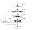
図6〜図12を参照して本実施例に係る画像処理装置として機能するパーソナルコンピュータPCにおける画像処理について説明する。図6は本実施例に係るパーソナルコンピュータPCにおいて実行される画像処理の処理ルーチンを示すフローチャートである。図7はパーソナルコンピュータPCにて実行される画像処理制御情報GCに基づく画像処理の処理ルーチンを示すフローチャートである。図8は本実施例に従う画像処理と階調数との関係を示す説明図である。図9は色空間変換の実行により、階調数が減少する様子を概念的に示す説明図である。図10は本実施例の作用効果により色空間変換の実行によっても、階調数を維持することができる様子を概念的に示す説明図である。図11はパーソナルコンピュータPCにて実行される通常画像処理の処理ルーチンを示すフローチャートである。図12はパーソナルコンピュータPCにて実行される画像データ出力処理の処理ルーチンを示すフローチャートである。
【0043】
ディジタルスチルカメラ12にて生成された画像ファイルGFは、ケーブルを介して、あるいは、メモリカードMCを介してパーソナルコンピュータPCに対して提供される。ユーザの操作によって、HDD152にインストールされている、レタッチアプリケーション、または、プリンタドライバといった画像データ処理アプリケーション(プログラム)が起動されると、CPU150は、画像ファイルGFの読み込みを開始する。
【0044】
あるいは、メモリカードMCのカードスロット153への差込、あるいは、入出力端子154に対するケーブルを介したディジタルスチルカメラ12の接続を検知することによって、CPU150は、画像処理アプリケーションを自動的に起動させ、画像ファイルGFの読み込みを開始しても良い。
【0045】
CPU150は、例えば、メモリカードMCから画像ファイルGFを読み出すと、読み出した画像ファイルGFをRAM151に一時的に格納して、画像ファイルGFの付属情報格納領域112において画像処理制御タグを検索する(ステップS100)。CPU150は、画像処理制御タグを検索・発見できた場合には(ステップS110:Yes)、画像データ生成時に書き込まれた画像処理制御情報GCを取得して解析する(ステップS120)。CPU150は、解析した画像処理制御情報GCに基づいて後に詳述する画像処理制御情報GCに基づく画像処理を実行し(ステップS130)、本処理ルーチンを終了する。
【0046】
CPU150は、画像処理制御タグを検索・発見できなかった場合には(ステップS110:No)、画像データ生成時における画像処理制御情報GCを反映させた画像処理を実行することができないので、通常の画像処理(ステップS140)を実行し、本処理ルーチンを終了する。
【0047】
パーソナルコンピュータPCにおいて実行される画像処理制御情報に基づく画像処理について図7を参照して詳細に説明する。パーソナルコンピュータPCのCPU150は、読み出した画像ファイルGFから画像データGDを取りだす(ステップS200)。このとき取り出された画像データGDは、オリジナルではなく、コピーであり、画像処理が完了するまでは、コピーの画像データGDに対して種々の画像処理が施される。
【0048】
ディジタルスチルカメラ12は、既述のように画像データをJPEG形式のファイルとして保存しており、JPEGファイルでは、圧縮率を高くするためにYCbCr色空間を用いて画像データを保存している。現在のところ、パーソナルコンピュータPCのCPUとして32ビットCPUが一般的に用いられているため、画像データの各成分、例えば、YCbCrデータで有れば、Y、Cb、Crの各成分には8ビットのデータサイズが割り当てられており、Y、Cb、Crの各成分は、0〜255の256の階調数(色数)で表され得る。そして、Y、Cb、Crの各成分の色彩値は、整数値として表され、各成分の色彩値がそれぞれ異なる整数値を取る場合には、Y、Cb、Crの各成分は、0〜255の256の階調数で表される。すなわち、階調数が大きくなった場合には画像データのデータサイズは必ず大きくなる。
【0049】
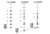
本実施例における特徴的な画像処理の概念について図9および図10を参照して説明する。本実施例では、CPU150は、画像処理を通じて元の画像データGDが有する階調数(色数)を維持するために、マトリクス演算Sによって得られた演算結果に対して有効数字の桁上げ処理を実行する。既述のように、画像データGDがYCbCr各成分について256階調(8ビット階調)で表されている場合には、図9に示すように画像データGDの色彩値は、有効数字が0〜3の整数値(0〜255)を取る。ところが、マトリクスSは、マトリクス係数に小数点を含むため、変換後の画像データGDの色彩値は、必ずしも整数値を取るとは限らない。このような画像データGDの色彩値を画像データとして取り扱うためには、整数値化する必要がある。整数値化するためには、有効数字の桁数を維持したまま小数点以下を四捨五入する等して整数値に丸め、整数値だけを有効数字として扱う方法が多く採られている。
【0050】
ところが、有効数字の桁数を維持したまま整数値への丸め処理を実行すると、図9に示すように、例えば、変換前は階調数が5であったのに対して、変換後は階調数が3に減少してしまう。すなわち、有効数字の桁数を増加すれば異なる複数の色彩値が、有効数字の桁数を維持することによって、同一の色彩値を有してしまうことになる。Sマトリクス演算は、本実施例における画像処理の最初の処理であり、この段階で階調数が減少してしまうと、後段の処理では正しく回復することはできず、画像処理の精度を低下させてしまう。また、階調数の減少は表色数の減少を意味するため、元の画像データと画像処理後の画像データとの間で、表色数が異なってしまう(少なくなってしまう)という問題も生じる。
【0051】
そこで、本実施例では、画像データGDに対してマトリクスSを実行した結果得られた変換後の画像データGDの有効数字の桁数を元の画像データGDの有効数字の桁数よりも増加させる桁上げ処理を実行する。すなわち、元の画像データGDの色彩値が1桁の場合は有効数字の桁数が1であるから、変換後の画像データGDの有効数字の桁数は2以上となり、元の画像データGDの色彩値が3桁の場合は有効数字の桁数が3であるから、変換後の画像データGDの有効数字の桁数は4以上となる。元の画像データの有効数字の桁数に対して変換後の画像データにどれだけの有効数字の桁数を認めるかは任意に決定される事項であるが、本実施例では、YCbCr、RGB各成分についての画像データの階調数を8ビット階調から18ビット階調に増加させる。このとき、画像データGDのサイズも8ビットから18ビットに増加する。
【0052】
この結果、階調数は、1024倍となり、図10に示すように、変換後のRGB色空間における色彩値の刻みが図9の場合と比較して細かくなり、小数点以下3桁までの値の色彩値で有れば変換後の画像データの色彩値を全て整数値化することができる。階調数が小数点以下3桁までの色彩値が整数値化されれば、階調数の減少を防止することが可能となり、元の画像データが有する階調数を後段の画像処理を通じて維持することができる。また、変換後の画像データの複数の色彩値が同一値を取る場合であっても、階調数が1024倍になるため、元の画像データGDの各成分について階調数256を容易に維持することが可能となり、表色数の減少を防止することができる。
【0053】
CPU150は、YCrCb色空間に基づく画像データをRGB色空間に基づく画像データに変換するために3×3マトリックス演算Sを実行する(ステップS210)。CPU150は、図8に示すようにマトリクス変換後の画像データGDの階調数を8ビット階調から18ビット階調に増加させて、マトリクス演算Sに伴う階調数の低下を防止する。マトリックス演算Sは以下に示す演算式である。
【0054】
【数1】

マトリクスS変換の結果、画像データ(色彩値)は負値あるいは256以上の正値を取ることがある(8ビット階調の場合)が、本実施例では、CPU150は、これら負値、あるいは、256以上の正値をそのまま維持して、以降の画像処理を継続する。
【0056】
CPU150は、こうして得られたRGB色空間に基づく画像データに対して、ガンマ補正を実行する(ステップS220)。ガンマ補正を実行する際には、CPU150は、画像処理制御情報GCからDSC側のガンマ値を取得し、取得したガンマ値を以下に示すガンマ補正演算式に用いて18ビット階調のガンマ補正テーブルをRAM151上に作成し、作成したガンマ補正テーブルを用いて画像データGDに対してガンマ変換処理を実行する。すなわち、ガンマ値も画像処理制御情報GCによって指定される画像処理制御パラメータ値に含まれる。ガンマ補正の演算式は以下の通りである。
【0057】
【数2】
CPU150は、ガンマ補正が実行された画像データGDに対して、原色空間とwRGB色空間とを対応付けるマトリックス演算(N-1M)を実行する(ステップS230)。CPU150は、マトリクス演算(N-1M)を実行して得られた変換後の画像データGDの階調数についても、マトリクス演算Sの場合と同様にして、図8に示すように、桁上げ処理によって18ビット階調から32ビット階調に増加させて階調数の減少を防止する。マトリクス演算における本実施例において用いられる画像ファイルGFは、画像生成時における色空間情報を含むことができるので、画像ファイルGFが色空間情報を含んでいる場合には、CPU150は、マトリックス演算(N-1M)を実行するに際して、色空間情報を参照し、画像生成時における色空間に対応するマトリックス(N-1M)を用いてマトリックス演算を実行する。
【0059】
マトリックス演算(N-1M)はRGB色空間をXYZ色空間に変換するためのマトリクスMを用いるマトリクス演算Mと、wRGB色空間をXYZ色空間に変換するためのマトリクスNを用いるマトリクス演算Nの逆マトリクス演算N-1との合成マトリクスである。マトリクスMは、sRGB色空間の表色域内には含まれないがデータとしては有効な画像データ(負の色彩値)を維持して、RGB色空間に基づく画像データを、XYZ色空間に基づく画像データに変換するためのマトリクスである。マトリクスMのマトリクス値は、色空間情報にしたがて決定される。マトリクスNの逆マトリクスNは、マトリクス演算MによってXYZ色空間に基づく画像データに変換された画像データをsRGB色空間よりも広い定義領域を有するwRGB色空間に変換(RGB色空間に戻す)ためのマトリクスである。XYZ色空間は、機器の出力特性に依存しない機器独立色空間の1つであり、RGB色空間とwRGB色空間との間における色彩値の対応付けを行うために用いられる。マトリックス演算(N-1M)は以下に示す演算式である。
【0060】
【数3】
マトリックス演算(N-1M)の実行後に得られる画像データGDの色空間はsRGB色空間よりも広い定義領域を有するwRGB色空間である。従来は、プリンタまたはコンピュータにおける画像処理に際して用いられる色空間はsRGBに固定されており、たとえ、プリンタがsRGB色空間よりも広くディジタルスチルカメラ12の表色域を含む表色域を有していてもディジタルスチルカメラ12の有する色空間を有効に活用することができなかった。これに対して、本実施例では、画像ファイルGFに色空間情報が含まれている場合には、色空間情報に対応してマトリックス演算Mに用いられるマトリックス(N-1M)を変更するので、ディジタルスチルカメラ12の有する色空間を有効に活用して、正しい色再現を実現することができる。
【0062】
CPU150は、マトリクス演算(N-1M)により得られた画像データに対して逆ガンマ補正を実行する(ステップS240)。CPU150は、図8に示すように、マトリクス演算(N-1M)により得られた画像データGDの階調数を32ビット階調から18ビット階調に減少させて、データサイズも32ビットから18ビットに減少する。階調数の減少は、32ビットの画像データGDの上位18ビットを画像データGDとして取り出すことによって実行される。ガンマ補正を実行する際には、CPU150はHDD152からプリンタ側のデフォルトのガンマ値を取得し、以下の逆ガンマ補正の演算式に取得したガンマ値の逆数を用いて逆ガンマ補正テーブルをRAM151に生成し、生成した逆ガンマ補正テーブルを用いて画像データGDに対して逆ガンマ変換処理を実行する。逆ガンマ補正に用いられる演算式は以下の通りである。
【0063】
【数4】
CPU150は、図8に示すように、逆ガンマ補正が施された画像データGDの階調数を18ビット階調から8ビット階調に減少させて、データサイズも18ビットから8ビットに減少する。逆ガンマ補正処理時には、逆ガンマ補正テーブルを生成する必要があり、階調数が大きい場合には、必要なメモリリソース量が増加すると共に、演算処理に時間を要する。一方で、人間の目によって認識される階調数は各成分について8ビット階調程度なので、出力結果には影響を及ぼさない。階調数の減少は、18ビットの画像データGDの上位8ビットを画像データGDとして取り出すことによって実行される。次に行われる自動画質調整では、R、G、Bの各成分を同時に処理する場合があり、各成分について8ビットの画像データしか扱うことができないからである。
【0065】
CPU150は、逆ガンマ補正が施された画像データGDに対して画像画質の自動調整処理を実行する(ステップS250)。本実施例における画質自動調整処理では、画像ファイルGFに含まれている画像データGDを解析して画質を示す特性パラメータ値を取得し、画像ファイルGFに含まれている画像処理制御情報GC、取得した特性パラメータ値を反映にて画像データを補正する画質の自動調整が実行される。画質自動調整処理では、補正の目標となるべき基準パラーメータを予め定めておき、基準パラメータと画像データの特性パラメータとの差分を解消または低減するように画質補正量を決定する。画像処理制御情報GCは、基準パラメータの値を変更するために用いられても良く、あるいは、画質補正量の適用レベルを変更するために用いられても良い。
【0066】
画像データの補正は、例えば、明度、コントラスト、カラーバランス等については、一般的にトーンカーブと呼ばれる、RGB信号の入力レベルと出力レベルとを関連づける特性線を用いて各画素(ピクセル)単位で実行される。また、例えば、彩度、シャープネス、ノイズ低減等については、トーンカーブ処理ではなくピクセル演算処理(フィルタ処理)がピクセル単位で実行される。
【0067】
CPU150は、画質自動調整処理を終了すると、処理済みの画像データをプリンタドライバへ出力して(ステップS260)、図6に示す処理ルーチンにリターンする。
【0068】
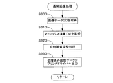
次に、パーソナルコンピュータPCにおいて実行される通常画像処理について図11を参照して詳細に説明する。なお、各ステップにおいて実行される処理のうち、図7を参照して説明した拡張画像処理における処理と同様の処理については、簡単に説明するにとどめる。パーソナルコンピュータPCのCPU150は、読み出した画像ファイルGFから画像データGDを取りだす(ステップS300)。CPU150は、YCrCb色空間に基づく画像データをsRGB色空間に基づく画像データに変換するために3×3マトリックス演算Sを実行する(ステップS310)。マトリックス演算Sは既述の演算式である。
【0069】
CPU31は、マトリクス演算Sにより得られた画像データに対して画像画質の自動調整処理を実行し(ステップS320)、画像処理を実行した画像データGDをプリンタドライバへ出力し(ステップS330)、図7に示す処理ルーチンにリターンする。
【0070】
図12を参照して、画像データGDの出力処理、すなわち、プリンタドライバ(印刷制御プログラム)によって実行される印刷制御処理について説明する。CPU150は、印刷ジョブに含まれる画像データを取得し(ステップS400)、印刷のためのRGB−CMYK色変換処理を実行する(ステップS410)。なお、色変換処理に先立って、画像データGDの解像度が印刷解像度よりも低い場合は、線形補間を行って隣接画像データ間に新たなデータを生成し、逆に印刷解像度よりも高い場合は、一定の割合でデータを間引くことによって、画像データの解像度を印刷解像度に変換する解像度変換処理が実行されても良い。
【0071】
ここまでのコピー画像データGDに対する画像処理の結果をオリジナル画像データGDに反映させる場合には、画像データの上書きを選択することにより実現される。画像ファイルGFから画像データ生成時に設定された色空間を取得できた場合であって、設定された色空間がsRGB色空間よりも広い色空間である場合には、例えば、wRGB−CMYK色変換テーブルが用いられ、画像処理制御タグを発見できない場合には、sRGB−CMYK色変換テーブルが用いられる。CPU150は、HDD152内に格納されている、wRGB色空間をCMYK色空間に関連づける変換用ルックアップテーブル(LUT)を参照し、画像データの色空間をwRGB色空間からCMYK色空間へ変更する。すなわち、R・G・Bの階調値からなる画像データをカラープリンタ20で使用する、例えば、C・M・Y・K・LC・LMの各6色の階調値のデータに変換する。
【0072】
CPU150は、ハーフトーン処理を実行し(ステップS420)、本処理ルーチンを終了する。ハーフトーン処理では、色変換済みの画像データを受け取って、階調数変換処理を行う。本実施例においては、色変換後の画像データは各色毎に256階調幅を持つデータとして表現されている。これに対し、本実施例のカラープリンタ20では、「ドットを形成する」,「ドットを形成しない」のいずれかの状態しか採り得ず、本実施例のカラープリンタ20は局所的には2階調しか表現し得ない。そこで、256階調を有する画像データを、カラープリンタ20が表現可能な2階調で表現された画像データに変換する。この2階調化(2値化)処理の代表的な方法として、誤差拡散法と呼ばれる方法と組織的ディザ法と呼ばれる方法とがある。CPU150は、ドットの形成有無を表す形式に変換された画像データを、カラープリンタ20に転送すべき順序に並べ替えてるインターレス処理をも実行する。
【0073】
以上、説明したように本実施例におけるパーソナルコンピュータPCによれば、画像データGDに対する画像処理の前後を通して画像データの階調数、表現色数を維持することができる。図9を参照して説明したように、一般的に、画像データGDの色空間を変換すると、変換後の画像データGDの色彩値の分布は不等間隔になってしまい、変換先の色空間における階調間隔に適合させる場合に(整数値化)、変換前の色空間では異なっていた複数の色彩値が変換後の色空間では同一の色彩値を取り、階調数が必ず減少してしまう。これに対して、本実施例に係るパーソナルコンピュータPCでは、画像データGDに対する最初の画像処理であるマトリクス演算Sの実行時に、階調数(画像データサイズ)を8ビットから18ビットに増加(有効数字の桁数を増加)させて、変換前の色空間で異なっていた複数の色彩値が変換後の色空間において同一の色彩値を取りにくくすることができる。また、階調数を256から262144に増加させているので、いくつかの色彩値が同一の値を取ったとしても、全体としては、256階調を維持することができる。したがって、元の画像データGDの階調数である256階調を維持することができると共に、1677万色の表色数を維持することができる。
【0074】
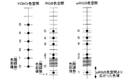
さらに、本実施例では、マトリクス演算SによりYCbCr色空間(表色系)からRGB色空間(表色系)へ色変換された画像データに含まれる負の色彩値を維持し、変換後の画像データを、発生した負の色彩値を色域内に含むwRGB色空間へマッピングする。したがって負の色彩値により表され得る色(階調)の欠落を防止し、色変換の前後において表色数の減少を防止することができる。この様子を図13および図14を参照して説明する。図13は、色空間変換の実行により発生した負の色彩値が欠落することにより、階調数が減少する様子を概念的に示す説明図である。図14は、本実施例の作用効果により色空間変換の実行によっても、負の色彩値により得られる階調数を維持することができる様子を概念的に示す説明図である。
【0075】
マトリクス演算Sにより得られたRGBデータには負の色彩値が含まれることがある。従来は図13に示すように、マトリクスSを用いた変換後得られた画像データは標準的なsRGB色空間にマッピングされていた。sRGB色空間へのマッピングにあたっては、sRGB色空間の色域外の色彩値、すなわち、負の色彩値は、256以上の色彩値(8ビットデータの場合)は、例えば、0,255の色彩値へとクリッピングする処理が実行されていた。かかる場合には、階調数を増加させたとしても、負の色彩値、256以上の色彩値は削られてしまうため、負の色彩値、256以上の色彩値によって表されていた階調、色数を維持することはできなかった。したがって、YCbCr色空間では6であった階調数(表色数)がsRGB色空間では、マトリクス演算および負の色彩値のクリッピングに伴い3に減少してしまう。
【0076】
これに対して、本実施例では、マトリクスSを用いた変換後得られた画像データはsRGB色空間よりも広い色域を有するwRGB色空間へとマッピングされる。したがって、図14に示すように、RGB色空間では負となる色彩値が、sRGB色空間より広がった色域によってwRGB色空間では正の色彩値となる。また、階調数を増加させることによって、色域の拡張およびマトリクス演算に伴う階調落ち、表色数の減少を防止することができる。この結果、YCbCr色空間では6であった階調数(表色数)は、wRGB色空間でも維持され、マトリクス演算Sの実行により予測される階調落ち、表色数の減少をより効果的に防止することができる。
【0077】
F.その他の実施例:
上記実施例では、パーソナルコンピュータPCにおいて、カラープリンタ20およびモニタ14に対して出力する画像データGDの画像処理を実行したが、全ての画像処理をカラープリンタ20にて実行しても良い。かかる場合には、カラープリンタ20によって、画像データGDの画像処理、画像処理が実行された画像データGDの印刷の全ての実現することができる。カラープリンタ20によって画像処理が実行される場合には、画像処理に利用することができるメモリリソースが限られているので、階調数の増減値を変更しても良い。例えば、各成分について8ビット階調の画像データGDに対してマトリクス演算Sを実行して18ビット階調とし、上位11ビットを用いてガンマ補正処理を実行して18ビット階調とし、マトリクス演算(N-1M)を実行して28ビット階調とし、上位12ビットを用いて逆ガンマ補正処理を実行して8ビット階調して自動画質調整処理を実行しても良い。かかる場合であっても、画像処理の途中で元の画像データの階調数に戻ることはないので、階調数は元の画像データが有する8ビットの階調は画像処理が施された後の画像データにおいても維持されることに変わりはない。
【0078】
また、画像処理の全て、または、一部をネットワークを介したサーバ上で実行するようにしても良い。
【0079】
以上、実施例に基づき本発明に係る画像処理装置、画像処理方法、画像処理プログラム、画像出力装置を説明してきたが、上記した発明の実施の形態は、本発明の理解を容易にするためのものであり、本発明を限定するものではない。本発明は、その趣旨並びに特許請求の範囲を逸脱することなく、変更、改良され得ると共に、本発明にはその等価物が含まれることはもちろんである。
【0080】
上記実施例用いた階調数はあくまでも例示に過ぎず、マトリクス演算Sを実行してから逆ガンマ補正を実行するまで32ビット階調を保持しても良い。また、パーソナルコンピュータPC等において利用可能なデータビット数が32ビットから64ビットに移行した場合には、32ビット階調に代えて64ビット階調を用いても良い。かかる場合には、画像処理時における階調落ちをさらに効果的に防止することができる。いずれの場合にも、元の画像データGDが有する8ビットの階調を画像処理終了時まで維持することができればよい。
【0081】
上記実施例では、マトリクス演算(N-1M)を実行した後に、階調数を減少させているが、逆ガンマ補正実行後、自動画質調整実行後に階調数を減少させるようにしても良い。また、本明細書中における階調数は例示に過ぎず、画像処理の前後を通して階調数が維持されればどのような階調数を取ってもよい。
【0082】
また、各数式におけるマトリックスS、N-1Mの値は例示に過ぎず、ターゲットとする色空間、あるいは、カラープリンタ20において利用可能な色空間等によって適宜変更され得ることはいうまでもない。
【0083】
上記実施例では、画像ファイル生成装置としてディジタルスチルカメラ12を用いて説明したが、この他にもスキャナ、ディジタルビデオカメラ等が用いられ得る。
【0084】
上記実施例では、画像ファイルGFの具体例としてExif形式のファイルを例にとって説明したが、本発明に係る画像ファイルの形式はこれに限られない。すなわち、画像データ生成装置において生成された画像データと、画像データの生成時条件(情報)を記述する画像処理制御情報GCとが含まれている画像ファイルであれば良い。このようなファイルであれば、画像ファイル生成装置において生成された画像データの画質を、適切に自動調整して出力装置から出力することができる。
【0085】
上記実施例では、画像データGDと画像処理制御情報GCとが同一の画像ファイルGFに含まれる場合を例にとって説明したが、画像データGDと画像処理制御情報GCとは、必ずしも同一のファイル内に格納される必要はない。すなわち、画像データGDと画像処理制御情報GCとが関連付けられていれば良く、例えば、画像データGDと画像処理制御情報GCとを関連付ける関連付けデータを生成し、1または複数の画像データと画像処理制御情報GCとをそれぞれ独立したファイルに格納し、画像データGDを処理する際に関連付けられた画像処理制御情報GCを参照しても良い。かかる場合には、画像データと画像処理制御情報GCとが別ファイルに格納されているものの、画像処理制御情報GCを利用する画像処理の時点では、画像データおよび画像処理制御情報GCとが一体不可分の関係にあり、実質的に同一のファイルに格納されている場合と同様に機能するからである。すなわち、少なくとも画像処理の時点において、画像データと画像処理制御情報GCとが関連付けられて用いられる態様は、本実施例における画像ファイルGFに含まれる。さらに、CD−ROM、CD−R、DVD−ROM、DVD−RAM等の光ディスクメディアに格納されている動画像ファイルも含まれる。
【図面の簡単な説明】
【図1】本実施例に係る画像処理装置を適用可能な画像処理システムの一例を示す説明図である。
【図2】本実施例に係る画像処理装置が処理する画像ファイル(画像データ)を生成可能なディジタルスチルカメラの概略構成を示すブロック図である。
【図3】本実施例において用いられ得るExifファイル形式にて格納されている画像ファイルの概略的な内部構造を示す説明図である。
【図4】本実施例におけるカラープリンタ20の概略構成を示すブロック図である。
【図5】本実施例に係るカラープリンタ20の制御回路30の内部構成を示す説明図である。
【図6】本実施例に係るパーソナルコンピュータPCにおいて実行される画像処理の処理ルーチンを示すフローチャートである。
【図7】パーソナルコンピュータPCにて実行される画像処理制御情報GCに基づく画像処理の処理ルーチンを示すフローチャートである。
【図8】本実施例に従う画像処理と階調数との関係を示す説明図である。
【図9】色空間変換の実行により、階調数が減少する様子を概念的に示す説明図である。
【図10】本実施例の作用効果により色空間変換の実行によっても、階調数を維持することができる様子を概念的に示す説明図である。
【図11】パーソナルコンピュータPCにて実行される通常画像処理の処理ルーチンを示すフローチャートである。
【図12】パーソナルコンピュータPCにて実行される画像データ出力処理の処理ルーチンを示すフローチャートである。
【図13】色空間変換の実行により発生した負の色彩値が欠落することにより、階調数が減少する様子を概念的に示す説明図である。
【図14】本実施例の作用効果により色空間変換の実行によっても、負の色彩値により得られる階調数を維持することができる様子を概念的に示す説明図である。
【符号の説明】
10…画像処理システム
12…ディジタルスチルカメラ
121…光学回路
122…画像取得回路
123…画像処理回路
124…制御回路
126…選択・決定ボタン
127…液晶ディスプレイ
14…ディスプレイ
150…CPU
151…RAM
152…HDD
153…カードスロット
154…入出力端子
20…カラープリンタ
21…操作パネル
30…キャリッジ
31…キャリッジモータ
32…プラテン
33…紙送りモータ
34…摺動軸
35…駆動ベルト
36…プーリ
37…エンコーダ
IH1、IH2、IH3、IH4…印字ヘッド
INC1…インクカートリッジ
INC2…インクカートリッジ
50…制御回路
51…演算処理装置(CPU)
52…プログラマブルリードオンリメモリ(PROM)
53…ランダムアクセスメモリ(RAM)
54…タイマ
55…周辺機器入出力部(PIO)
56…駆動バッファ
57…バス
58…発振器
59…分配出力器
GF…画像ファイル(Exifファイル)
GD…画像データ
111…JPEG画像データ格納領域
112…付属情報格納領域
MC…メモリカード
PC…パーソナルコンピュータ[0001]
BACKGROUND OF THE INVENTION
The present invention relates to an image processing apparatus and an image processing program that perform image processing on an image file.
[0002]
[Prior art]
Currently, image data based on various color spaces is used in image data processing apparatuses such as computers, printers, and digital still cameras. For example, in a computer, image data based on an RGB color space is normally used on the assumption that the image is output to a monitor. In a digital still camera (DSC), the generated image data is compressed and stored in the JPEG format. Therefore, image data based on a YCbCr color space suitable for data compression is used. Therefore, for example, when image data generated by DSC is processed by a computer, it is necessary to convert the color space of the image data from the YCbCr color space to the RGB color space.
[0003]
[Problems to be solved by the invention]
However, when the color space of the image data is converted from the first color space (YCbCr) to the second color space (RGB), the color values arranged at equal intervals in the first color space are converted into the second color space. In this case, the number of gradations (color number) of the converted image data is reduced compared to the number of gradations (color number) of the image data before conversion. was there. When the number of gradations decreases, the number of colors that can be reproduced decreases, so that the color of the image data cannot be accurately expressed, and there is a problem that only an output image with gradation skips can be obtained.
[0004]
The present invention has been made to solve the above problems, and an object of the present invention is to maintain the number of gradations and the number of colors of image data before and after image processing conversion.
[0005]
[Means for solving the problems and their functions and effects]
In order to solve the above problems, a first aspect of the present invention provides an image processing apparatus that performs image processing on image data. An image processing apparatus according to a first aspect of the present invention is a color system in a first color coordinate system, and image data of a first color system that can represent the first number of colors, To a second color system image data that is a color system in a color coordinate system of 2 and can color a second color number larger than the first color number. , Ma Color conversion means for converting by trick operation, image processing means for executing image processing on the converted image data in the second color system, and the number of color specifications of the image data subjected to the image processing And a means for reducing the number of colors.
[0006]
According to the image processing apparatus of the first aspect of the present invention, the image data of the first color system that can color the first number of colors in the first color coordinate system is converted into the second color coordinate system. To image data of a second color system that can represent a second color number larger than the first color number in , Ma Since it can be converted by the tricks operation, the number of gradations and the number of colors of the image data are maintained before and after the color conversion process (image processing) even when the color conversion process is executed between different color coordinate systems. be able to.
[0007]
In the image processing apparatus according to the first aspect of the present invention, the image processing executed by the image processing means may include gamma correction processing, and includes color conversion processing using a second matrix operation. It may be.
[0008]
In the image processing apparatus according to the first aspect of the present invention, the first color system may be a YCC color system, and the second color system may be an sRGB color system, or The first color system may be a YCC color system, and the second color system may be a wRGB color system having a wider color gamut than the sRGB color system. In any case, the first number of colors is maintained after color conversion. In particular, when the wRGB color system is used, negative color values that are not represented in the sRGB color system may be represented. it can.
[0009]
In the image processing apparatus according to the first aspect of the present invention, the second color number of the second color system is changed from the first color system to the second color system by the color conversion unit. The number of colors represented by a negative value included in the image data converted into may be included. In such a case, even if the image data converted from the first color system to the second color system contains a negative value, the color value represented by the negative value is lost. Color can be displayed without any problem.
[0010]
A second aspect of the present invention provides an image processing apparatus that performs image processing on image data. In the image processing apparatus according to the first aspect of the present invention, the color value of the image data represented by an integer value having a first significant digit is set to a number of digits larger than the number of digits of the first significant digit. A first image processing means for changing to a first value, and a gradation number reduction preventing means for preventing a decrease in the number of gradations of the image data due to a change in color value by the first image processing means; And a second image processing means for changing a color value of the image data having the first value from the first value to a second value reflected in an image output result.
[0011]
According to the image processing apparatus of the second aspect of the present invention, it is possible to prevent a decrease in the number of gradations of the image data due to the change of the color value to the first value, and the color of the image data having the first value. Since the value is changed from the first value to the second value reflected in the image output result, the number of gradations and the number of expression colors of the image data can be maintained before and after the image processing conversion.
[0012]
In the image processing apparatus according to the second aspect of the present invention, the gradation number reduction preventing means sets the significant digits of the first value up to the number of digits greater than the number of digits of the first significant digit. Thus, a decrease in the number of gradations of the image data may be prevented. In such a case, even when integer values having a plurality of different first significant digits take the same first value, the number of significant digits increases, so the original number of gradations is maintained. be able to. Note that the data size of the image data in which the reduction in the number of gradations is prevented by the gradation number reduction preventing means may be larger than the data size of the image data represented by the integer value having the first significant digit. good. Since the number of significant digits of the image data increases, the data size of the image data increases.
[0013]
In the image processing apparatus according to the second aspect of the present invention, the first image processing means is a color space conversion means for converting a color space of the image data from a first color space to a second color space. May be. The color space conversion unit converts the color space of the image data from a YCbCr color space to an RGB color space, and converts the color value of the image data represented by an integer value having the first significant digit to a decimal point. You may change to the said 1st value containing. By increasing the number of significant digits, the number of gradations can be maintained even when the first value includes a decimal point.
[0014]
A third aspect of the present invention provides an image processing apparatus that performs image processing on image data. The image processing apparatus according to the third aspect of the present invention increases the number of gradations of the image data from the first number of gradations to the second number of gradations, and changes the color space of the image data from the YCbCr color space. first color space conversion means for converting to sRGB color space; gamma correction means for executing gamma correction processing on the image data converted from the color space; and color of the image data on which the gamma correction processing has been executed. A second color space conversion means for converting the space from the sRGB color space to a wRGB color space having a definition area wider than the sRGB color space, and the number of gradation levels of the image data converted from the color space. Gradation number reduction means for returning the number of gradations to the first gradation number.
[0015]
According to the image processing apparatus of the third aspect of the present invention, the color space of the image data is changed to the YCbCr color space while increasing the number of gradations of the image data from the first number of gradations to the second number of gradations. To the sRGB color space, the number of gradations and the number of expression colors of the image data can be maintained before and after the image processing conversion.
[0016]
The image processing apparatus according to the third aspect of the present invention further includes
A reverse gamma correction unit that performs a reverse gamma correction process on the image data in which the color space is converted;
The gradation number reduction means changes the gradation number of the image data on which the inverse gamma correction has been executed from the second gradation number to the first gradation instead of the image data in which the color space is converted. You may return to the number. In such a case, the gradation accuracy in the inverse gamma correction process can be maintained or improved.
[0017]
The image processing apparatus according to the third aspect of the present invention further includes
Image correction means for automatically correcting the image quality of the image data subjected to the inverse gamma correction,
The gradation number reduction means changes the gradation number of the image data whose image quality has been corrected from the second gradation number to the first gradation number instead of the image data on which the inverse gamma correction has been executed. You may return to. In such a case, the gradation accuracy in the image correction process can be maintained or improved.
[0018]
A fourth aspect of the present invention provides an output device that outputs image data subjected to image processing. A printing apparatus according to a fourth aspect of the present invention includes an image processing apparatus according to any one of the first to third aspects of the present invention, and an output for outputting image data subjected to image processing by the image processing apparatus. Means.
[0019]
The output device according to the fourth aspect of the present invention can output image data with good gradation.
[0020]
A fifth aspect of the present invention provides an image processing program for executing image processing on image data. An image processing program according to a fifth aspect of the present invention is a color system in the first color coordinate system, and the image data of the first color system that can represent the first number of colors, To a second color system image data that is a color system in a color coordinate system of 2 and can color a second color number larger than the first color number. , Ma A function of converting by the trick operation, a function of executing image processing on the converted image data in the second color system, and a function of reducing the number of color specifications of the image data subjected to the image processing Is realized by a computer.
Others: The amendment in this amendment is an amendment that deletes “holding the first number of colors” and does not introduce a new matter.
[0021]
According to the image processing program of the fifth aspect of the present invention, it is possible to obtain the same operational effects as those of the image processing apparatus according to the first aspect of the present invention. Further, the image processing program according to the fifth aspect of the present invention can be realized in various aspects in the same manner as the image processing apparatus according to the first aspect of the present invention.
[0022]
A sixth aspect of the present invention provides an image processing program for executing image processing on image data. An image processing program according to a sixth aspect of the present invention provides a color value of the image data represented by an integer value having a first significant digit, a number of digits larger than the number of digits of the first significant digit. A first image processing function for changing to a first value, a function for preventing a decrease in the number of gradations of the image data associated with a change in color value by the first image processing means, and the first value And a second image processing function for changing the color value of the image data having image data from the first value to the second value reflected in the image output result.
[0023]
According to the image processing program of the sixth aspect of the present invention, it is possible to obtain the same operational effects as those of the image processing apparatus according to the second aspect of the present invention. Further, the image processing program according to the sixth aspect of the present invention can be realized in various aspects in the same manner as the image processing apparatus according to the second aspect of the present invention.
[0024]
A seventh aspect of the present invention provides an image processing program for executing image processing on image data. The image processing program according to the seventh aspect of the present invention increases the number of gradations of the image data from the first number of gradations to the second number of gradations, and changes the color space of the image data from the YCbCr color space. a first color space conversion function for converting to the sRGB color space; a gamma correction function for executing gamma correction processing on the image data converted from the color space; and the color of the image data on which the gamma correction processing has been executed. A second color space conversion function for converting the space from the sRGB color space to a wRGB color space having a wider definition area than the sRGB color space, and the number of gradations of the image data converted from the color space. A gradation reduction function for returning the number of gradations to the first gradation is realized by a computer.
[0025]
According to the image processing program concerning the 7th mode of the present invention, the same operation effect as the image processing device concerning the 3rd mode of the present invention can be obtained. Further, the image processing program according to the seventh aspect of the present invention can be realized in various aspects in the same manner as the image processing apparatus according to the third aspect of the present invention.
[0026]
DETAILED DESCRIPTION OF THE INVENTION
Hereinafter, an image processing apparatus according to the present invention will be described based on several embodiments with reference to the drawings in the following order.
A. Image processing system configuration:
B. Image file structure:
C. Image processing in the image processing apparatus:
D. Other examples:
[0027]
A. Image processing system configuration:
The configuration of an image processing system to which the image processing apparatus according to this embodiment can be applied will be described with reference to FIGS. FIG. 1 is an explanatory diagram illustrating an example of an image processing system to which the image processing apparatus according to the present embodiment can be applied. FIG. 2 is a block diagram illustrating a schematic configuration of a digital still camera capable of generating an image file (image data) output from the image processing apparatus according to the present embodiment. FIG. 3 is a schematic diagram showing the internal configuration of a color printer that can be applied to this embodiment. FIG. 4 is a block diagram showing the internal configuration of the control circuit of the
[0028]
An
[0029]
The personal computer PC is a commonly used type of computer. The
[0030]
As shown in FIG. 2, the digital
[0031]
The digital
[0032]
The digital
[0033]
The image file GF generated in the digital
[0034]
The internal configuration of the image output apparatus used in this embodiment, that is, the
[0035]
As shown in the figure, the
[0036]
The
[0037]
Next, the internal configuration of the
[0038]
B. Image file structure:
A schematic configuration of an image file that can be used in this embodiment will be described with reference to FIG. FIG. 5 is an explanatory diagram conceptually showing an example of the internal configuration of an image file that can be used in this embodiment. The image file GF according to the present embodiment can have a file structure in accordance with, for example, a digital still camera image file format standard (Exif). The specification of the Exif file is determined by the Japan Electronics Industry Promotion Association (JEIDA).
[0039]
The image file GF as an Exif file includes a JPEG image
[0040]
The image processing control information GC is information related to the image quality when image data is generated (taken) in an image data generation device such as the digital
[0041]
The image file GF according to the present embodiment can be generated not only by the digital
[0042]
C. Image processing in the image processing apparatus:
Image processing in a personal computer PC functioning as an image processing apparatus according to the present embodiment will be described with reference to FIGS. FIG. 6 is a flowchart showing a processing routine of image processing executed in the personal computer PC according to the present embodiment. FIG. 7 is a flowchart showing a processing routine of image processing based on the image processing control information GC executed by the personal computer PC. FIG. 8 is an explanatory diagram showing the relationship between image processing and the number of gradations according to the present embodiment. FIG. 9 is an explanatory diagram conceptually showing a state in which the number of gradations decreases due to the execution of color space conversion. FIG. 10 is an explanatory diagram conceptually showing a state in which the number of gradations can be maintained by executing the color space conversion by the effect of this embodiment. FIG. 11 is a flowchart showing a processing routine of normal image processing executed by the personal computer PC. FIG. 12 is a flowchart showing a processing routine of image data output processing executed by the personal computer PC.
[0043]
The image file GF generated by the digital
[0044]
Alternatively, by detecting the insertion of the memory card MC into the
[0045]
For example, when reading the image file GF from the memory card MC, the
[0046]
If the image processing control tag cannot be searched / discovered (step S110: No), the
[0047]
Image processing based on image processing control information executed in the personal computer PC will be described in detail with reference to FIG. The
[0048]
The digital
[0049]
The concept of characteristic image processing in this embodiment will be described with reference to FIGS. In the present embodiment, the
[0050]
However, when rounding to an integer value is performed while maintaining the number of significant digits, for example, as shown in FIG. The logarithm is reduced to 3. In other words, if the number of significant digits is increased, a plurality of different color values have the same color value by maintaining the number of significant digits. The S matrix calculation is the first processing of the image processing in this embodiment, and if the number of gradations decreases at this stage, it cannot be recovered correctly in the subsequent processing, reducing the accuracy of the image processing. End up. In addition, since the reduction in the number of gradations means a reduction in the number of color specifications, there is also a problem that the number of color specifications is different (reduced) between the original image data and the image data after image processing. Arise.
[0051]
Therefore, in this embodiment, the number of significant digits of the converted image data GD obtained as a result of executing the matrix S on the image data GD is increased more than the number of significant digits of the original image data GD. Execute carry processing. That is, when the color value of the original image data GD is 1 digit, the number of significant digits is 1, so that the number of significant digits of the converted image data GD is 2 or more, and the original image data GD When the color value is 3 digits, the number of significant digits is 3, so the number of significant digits of the converted image data GD is 4 or more. The number of significant digits in the converted image data with respect to the number of significant digits of the original image data is arbitrarily determined, but in this embodiment, each of YCbCr and RGB The number of gradations of the image data for the component is increased from the 8-bit gradation to the 18-bit gradation. At this time, the size of the image data GD also increases from 8 bits to 18 bits.
[0052]
As a result, the number of gradations becomes 1024 times, and as shown in FIG. 10, the increment of the color value in the RGB color space after conversion becomes finer than in the case of FIG. If it is a color value, all the color values of the converted image data can be converted to integer values. If the color value of the number of gradations up to 3 digits after the decimal point is converted to an integer value, it becomes possible to prevent the decrease in the number of gradations and maintain the gradation number of the original image data through subsequent image processing. be able to. Further, even when a plurality of color values of the converted image data have the same value, the number of gradations is 1024 times, so that the number of gradations 256 is easily maintained for each component of the original image data GD. It is possible to prevent the decrease in the number of color specifications.
[0053]
The
[0054]
[Expression 1]
As a result of the matrix S conversion, the image data (color value) may take a negative value or a positive value of 256 or more (in the case of 8-bit gradation). In this embodiment, the
[0056]
The
[0057]
[Expression 2]
The
[0059]
Matrix operation (N -1 M) is an inverse matrix operation N of a matrix operation M using a matrix M for converting the RGB color space to the XYZ color space and a matrix operation N using the matrix N for converting the wRGB color space to the XYZ color space. -1 Is a composite matrix. The matrix M is not included in the color gamut of the sRGB color space but maintains valid image data (negative color values) as data, and image data based on the RGB color space is converted into an image based on the XYZ color space. It is a matrix for converting to data. The matrix value of the matrix M is determined according to the color space information. An inverse matrix N of the matrix N is used to convert (return to the RGB color space) image data converted into image data based on the XYZ color space by the matrix operation M into a wRGB color space having a definition area wider than the sRGB color space. Matrix. The XYZ color space is one of device-independent color spaces that do not depend on the output characteristics of the device, and is used to associate color values between the RGB color space and the wRGB color space. Matrix operation (N -1 M) is an arithmetic expression shown below.
[0060]
[Equation 3]
Matrix operation (N -1 The color space of the image data GD obtained after the execution of M) is a wRGB color space having a definition area wider than the sRGB color space. Conventionally, the color space used for image processing in a printer or a computer is fixed to sRGB. For example, the printer has a color gamut including the color gamut of the digital
[0062]
The
[0063]
[Expression 4]
As shown in FIG. 8, the
[0065]
The
[0066]
Image data correction, for example, for brightness, contrast, color balance, etc., is performed for each pixel (pixel) using a characteristic line that associates the input level and output level of an RGB signal, generally called a tone curve. Is done. Further, for example, for saturation, sharpness, noise reduction, etc., pixel calculation processing (filter processing) is executed in units of pixels instead of tone curve processing.
[0067]
When the automatic image quality adjustment processing is completed, the
[0068]
Next, normal image processing executed in the personal computer PC will be described in detail with reference to FIG. Of the processing executed in each step, processing similar to that in the extended image processing described with reference to FIG. 7 will be briefly described. The
[0069]
The
[0070]
With reference to FIG. 12, the output process of the image data GD, that is, the print control process executed by the printer driver (print control program) will be described. The
[0071]
When the result of the image processing for the copy image data GD so far is reflected in the original image data GD, it is realized by selecting overwriting of the image data. When the color space set at the time of image data generation can be acquired from the image file GF and the set color space is a color space wider than the sRGB color space, for example, a wRGB-CMYK color conversion table. When the image processing control tag cannot be found, the sRGB-CMYK color conversion table is used. The
[0072]
The
[0073]
As described above, according to the personal computer PC in this embodiment, the number of gradations and the number of expression colors of the image data can be maintained before and after the image processing on the image data GD. As described with reference to FIG. 9, generally, when the color space of the image data GD is converted, the distribution of the color values of the converted image data GD becomes unequal, and the color space of the conversion destination When adapting to the gradation interval in the image (converting to an integer value), multiple color values that were different in the color space before conversion take the same color value in the color space after conversion, and the number of gradations must be reduced. End up. On the other hand, in the personal computer PC according to the present embodiment, the number of gradations (image data size) is increased from 8 bits to 18 bits (effective) when the matrix operation S which is the first image processing for the image data GD is executed. By increasing the number of digits), it is possible to make it difficult for a plurality of color values that were different in the color space before conversion to take the same color value in the color space after conversion. Also, since the number of gradations is increased from 256 to 262144, even if several color values have the same value, 256 gradations can be maintained as a whole. Therefore, it is possible to maintain 256 gradations, which is the number of gradations of the original image data GD, and to maintain the number of color specifications of 16.77 million colors.
[0074]
Furthermore, in this embodiment, the negative color value included in the image data that has been color-converted from the YCbCr color space (color system) to the RGB color space (color system) by the matrix operation S is maintained, and the converted image Data is mapped to a wRGB color space that includes the generated negative color values within the color gamut. Accordingly, it is possible to prevent a color (gradation) that can be represented by a negative color value from being lost, and to prevent a decrease in the number of color specifications before and after color conversion. This will be described with reference to FIG. 13 and FIG. FIG. 13 is an explanatory diagram conceptually illustrating a state in which the number of gradations is reduced due to the loss of negative color values generated by the execution of color space conversion. FIG. 14 is an explanatory diagram conceptually showing a state in which the number of gradations obtained by a negative color value can be maintained even by executing color space conversion by the effect of this embodiment.
[0075]
The RGB data obtained by the matrix operation S may include negative color values. Conventionally, as shown in FIG. 13, the image data obtained after conversion using the matrix S is mapped to a standard sRGB color space. In mapping to the sRGB color space, color values outside the color gamut of the sRGB color space, that is, negative color values are 256 or more (in the case of 8-bit data), for example, to 0,255 color values. Clipping processing was executed. In such a case, even if the number of gradations is increased, the negative color value, the color value of 256 or more is deleted, so the gradation represented by the negative color value, the color value of 256 or more, The number of colors could not be maintained. Therefore, in the sRGB color space, the number of gradations (color number) that was 6 in the YCbCr color space is reduced to 3 in the sRGB color space due to the matrix operation and the negative color value clipping.
[0076]
On the other hand, in this embodiment, the image data obtained after conversion using the matrix S is mapped into the wRGB color space having a wider color gamut than the sRGB color space. Therefore, as shown in FIG. 14, a color value that is negative in the RGB color space becomes a positive color value in the wRGB color space due to a color gamut that is wider than the sRGB color space. In addition, by increasing the number of gradations, it is possible to prevent gradation drop and decrease in the number of colorimetrics accompanying expansion of the color gamut and matrix calculation. As a result, the number of gradations (the number of color specifications) that was 6 in the YCbCr color space is maintained in the wRGB color space, and the gradation drop predicted by the execution of the matrix operation S and the reduction in the number of color expressions are more effective. Can be prevented.
[0077]
F. Other examples:
In the above embodiment, the image processing of the image data GD output to the
[0078]
Further, all or part of the image processing may be executed on a server via a network.
[0079]
As described above, the image processing apparatus, the image processing method, the image processing program, and the image output apparatus according to the present invention have been described based on the embodiments. However, the above-described embodiments of the present invention are intended to facilitate understanding of the present invention. However, the present invention is not limited thereto. The present invention can be changed and improved without departing from the spirit and scope of the claims, and it is needless to say that the present invention includes equivalents thereof.
[0080]
The number of gradations used in the above embodiment is merely an example, and 32-bit gradations may be held from when the matrix operation S is executed until the inverse gamma correction is executed. In addition, when the number of data bits that can be used in a personal computer PC or the like shifts from 32 bits to 64 bits, a 64-bit gradation may be used instead of the 32-bit gradation. In such a case, it is possible to more effectively prevent gradation drop during image processing. In any case, it is sufficient that the 8-bit gradation of the original image data GD can be maintained until the end of the image processing.
[0081]
In the above embodiment, matrix calculation (N -1 Although the number of gradations is decreased after executing M), the number of gradations may be decreased after execution of inverse gamma correction and after execution of automatic image quality adjustment. In addition, the number of gradations in this specification is merely an example, and any number of gradations may be taken as long as the number of gradations is maintained before and after image processing.
[0082]
In addition, the matrix S, N in each formula -1 The value of M is merely an example, and it is needless to say that the value of M can be changed as appropriate depending on the target color space or the color space available in the
[0083]
In the above embodiment, the digital
[0084]
In the above embodiment, the Exif format file has been described as a specific example of the image file GF, but the format of the image file according to the present invention is not limited to this. That is, any image file including image data generated by the image data generation device and image processing control information GC describing conditions (information) at the time of image data generation may be used. With such a file, the image quality of the image data generated by the image file generation device can be automatically adjusted appropriately and output from the output device.
[0085]
In the above embodiment, the case where the image data GD and the image processing control information GC are included in the same image file GF has been described as an example. However, the image data GD and the image processing control information GC are not necessarily included in the same file. It need not be stored. That is, it is only necessary that the image data GD and the image processing control information GC are associated with each other. For example, association data that associates the image data GD and the image processing control information GC is generated, and one or a plurality of image data and the image processing control are generated. The information GC may be stored in independent files, and the image processing control information GC associated with the processing of the image data GD may be referred to. In such a case, although the image data and the image processing control information GC are stored in separate files, the image data and the image processing control information GC are inseparably integrated at the time of image processing using the image processing control information GC. This is because they function in the same manner as when they are stored in substantially the same file. That is, an aspect in which image data and image processing control information GC are used in association with each other at least at the time of image processing is included in the image file GF in the present embodiment. Furthermore, a moving image file stored in an optical disc medium such as a CD-ROM, a CD-R, a DVD-ROM, a DVD-RAM is also included.
[Brief description of the drawings]
FIG. 1 is an explanatory diagram illustrating an example of an image processing system to which an image processing apparatus according to an embodiment can be applied.
FIG. 2 is a block diagram illustrating a schematic configuration of a digital still camera capable of generating an image file (image data) to be processed by the image processing apparatus according to the present embodiment.
FIG. 3 is an explanatory diagram showing a schematic internal structure of an image file stored in an Exif file format that can be used in this embodiment.
FIG. 4 is a block diagram illustrating a schematic configuration of a
FIG. 5 is an explanatory diagram showing an internal configuration of a
FIG. 6 is a flowchart illustrating a processing routine of image processing executed in the personal computer PC according to the present embodiment.
FIG. 7 is a flowchart showing a processing routine of image processing based on image processing control information GC executed by the personal computer PC.
FIG. 8 is an explanatory diagram showing a relationship between image processing and the number of gradations according to the present embodiment.
FIG. 9 is an explanatory diagram conceptually illustrating a state in which the number of gradations is reduced by executing color space conversion.
FIG. 10 is an explanatory diagram conceptually illustrating a state in which the number of gradations can be maintained even by executing color space conversion by the effect of the present embodiment.
FIG. 11 is a flowchart showing a processing routine of normal image processing executed by the personal computer PC.
FIG. 12 is a flowchart showing a processing routine of image data output processing executed by the personal computer PC.
FIG. 13 is an explanatory diagram conceptually illustrating a state in which the number of gradations is decreased due to the loss of negative color values generated by the execution of color space conversion.
FIG. 14 is an explanatory diagram conceptually illustrating a state in which the number of gradations obtained by a negative color value can be maintained even by executing color space conversion by the effect of the present embodiment.
[Explanation of symbols]
10. Image processing system
12 ... Digital still camera
121: Optical circuit
122. Image acquisition circuit
123: Image processing circuit
124 ... Control circuit
126 ... Select / Enter button
127 ... Liquid crystal display
14 ... Display
150 ... CPU
151 ... RAM
152 ... HDD
153: Card slot
154 ... Input / output terminals
20 Color printer
21 ... Control panel
30 ... carriage
31 ... Carriage motor
32 ... Platen
33 ... Paper feed motor
34 ... Sliding shaft
35 ... Driving belt
36 ... pulley
37 ... Encoder
IH1, IH2, IH3, IH4 ... Print head
INC1 ... ink cartridge
INC2 ... Ink cartridge
50 ... Control circuit
51. Arithmetic processing unit (CPU)
52. Programmable read only memory (PROM)
53 ... Random access memory (RAM)
54 ... Timer
55 ... Peripheral device input / output unit (PIO)
56 ... Drive buffer
57 ... Bus
58 ... Oscillator
59 ... Distribution output device
GF ... Image file (Exif file)
GD ... Image data
111 ... JPEG image data storage area
112 ... Attached information storage area
MC ... Memory card
PC ... Personal computer
Claims (5)
前記画像データの階調数を第1の階調数から第2の階調数に増加させると共に、画像データの色空間をYCbCr色空間からRGB色空間に変換する第1の色空間変換手段と、
前記色空間が変換された画像データに対してガンマ補正処理を実行するガンマ補正手段と、
前記画像データの階調数を前記第2の階調数から第3の階調数に増加させて、前記ガンマ補正処理が実行された画像データの色空間を前記RGB色空間からsRGB色空間よりも広い定義領域を有し、前記RGB色空間とは異なるwRGB色空間に変換する第2の色空間変換手段と、
前記色空間が変換された前記画像データの階調数を前記第3の階調数から前記第2の階調数に減少させて、前記色空間が変換された画像データに対して逆ガンマ補正処理を実行する逆ガンマ補正手段と、
前記逆ガンマ補正が実行がされた画像データの階調数を前記第2の階調数から前記第1の階調数に戻す階調数低減手段とを備える画像処理装置。An image processing apparatus that executes image processing on image data,
First color space conversion means for increasing the number of gradations of the image data from the first number of gradations to the second number of gradations and converting the color space of the image data from the YCbCr color space to the RGB color space; ,
Gamma correction means for performing gamma correction processing on the image data in which the color space is converted;
By increasing the number of gradations of the image data from the second number of gradations to the third number of gradations, the color space of the image data on which the gamma correction processing has been executed is changed from the RGB color space to the sRGB color space. A second color space conversion means for converting to a wRGB color space different from the RGB color space,
Inverse gamma correction is performed on the image data in which the color space has been converted by reducing the number of gradations in the image data in which the color space has been converted from the third gradation number to the second gradation number. An inverse gamma correction means for executing processing ;
An image processing apparatus comprising: a gradation number reduction unit that returns the gradation number of the image data on which the inverse gamma correction has been performed from the second gradation number to the first gradation number.
前記逆ガンマ補正が実行された画像データの画質を補正する画像補正手段を備え、
前記階調数低減手段は、前記逆ガンマ補正が実行がされた画像データに代えて、前記画質が補正された画像データの階調数を前記第2の階調数から第1の階調数に戻すことを特徴とする画像処理装置。The image processing apparatus according to claim 1 further includes:
Image correction means for correcting the image quality of the image data subjected to the inverse gamma correction;
The gradation number reduction means changes the gradation number of the image data whose image quality has been corrected from the second gradation number to the first gradation number instead of the image data on which the inverse gamma correction has been executed. An image processing apparatus, wherein
請求項1または請求項2に記載の画像処理装置と、
前記画像処理装置によって画像処理の施された画像データを出力する出力手段とを備える出力装置。An output device for outputting image data subjected to image processing,
The image processing apparatus according to claim 1 or 2 ,
An output device comprising: output means for outputting image data subjected to image processing by the image processing device.
前記画像データの階調数を第1の階調数から第2の階調数に増加させると共に、画像データの色空間をYCbCr色空間からsRGB色空間に変換する第1の色空間変換機能と、
前記色空間が変換された画像データに対してガンマ補正処理を実行するガンマ補正機能と、
前記画像データの階調数を前記第2の階調数から第3の階調数に増加させて、前記ガンマ補正処理が実行された画像データの色空間をsRGB色空間からsRGB色空間よりも広い定義領域を有するwRGB色空間に変換する第2の色空間変換機能と、
前記色空間が変換された前記画像データの階調数を前記第3の階調数から前記第2の階調数に減少させて、前記色空間が変換された画像データに対して逆ガンマ補正処理を実行する逆ガンマ補正機能と、
前記逆ガンマ補正が実行がされた画像データの階調数を前記第2の階調数から前記第1の階調数に戻す階調数低減機能とをコンピュータによって実現させる画像処理プログラム。An image processing program for executing image processing on image data,
A first color space conversion function for increasing the number of gradations of the image data from the first number of gradations to the second number of gradations and converting the color space of the image data from the YCbCr color space to the sRGB color space; ,
A gamma correction function for performing gamma correction processing on the image data in which the color space is converted;
By increasing the number of gradations of the image data from the second number of gradations to the third number of gradations, the color space of the image data subjected to the gamma correction processing is changed from the sRGB color space to the sRGB color space. A second color space conversion function for converting to a wRGB color space having a wide definition area;
Inverse gamma correction is performed on the image data in which the color space has been converted by reducing the number of gradations in the image data in which the color space has been converted from the third gradation number to the second gradation number. An inverse gamma correction function to execute the process ,
An image processing program for realizing, by a computer, a gradation number reduction function for returning the gradation number of image data on which the inverse gamma correction has been performed from the second gradation number to the first gradation number.
前記逆ガンマ補正が実行された画像データの画質を自動的に補正する画像補正機能をコンピュータによって実現させ、
前記階調数低減機能は、前記逆ガンマ補正が実行がされた画像データに代えて、前記画質が補正された画像データの階調数を前記第2の階調数から第1の階調数に戻す機能であることを特徴とする画像処理プログラム。The image processing program according to claim 4 further includes:
An image correction function for automatically correcting the image quality of the image data subjected to the inverse gamma correction is realized by a computer,
The gradation number reduction function is configured to change the gradation number of the image data whose image quality has been corrected from the second gradation number to the first gradation number instead of the image data on which the inverse gamma correction has been executed. An image processing program characterized by having the function of returning to
Priority Applications (1)
| Application Number | Priority Date | Filing Date | Title |
|---|---|---|---|
| JP2002070128A JP4295465B2 (en) | 2001-03-15 | 2002-03-14 | Image processing device |
Applications Claiming Priority (3)
| Application Number | Priority Date | Filing Date | Title |
|---|---|---|---|
| JP2001-74553 | 2001-03-15 | ||
| JP2001074553 | 2001-03-15 | ||
| JP2002070128A JP4295465B2 (en) | 2001-03-15 | 2002-03-14 | Image processing device |
Publications (3)
| Publication Number | Publication Date |
|---|---|
| JP2002344763A JP2002344763A (en) | 2002-11-29 |
| JP2002344763A5 JP2002344763A5 (en) | 2005-06-23 |
| JP4295465B2 true JP4295465B2 (en) | 2009-07-15 |
Family
ID=26611355
Family Applications (1)
| Application Number | Title | Priority Date | Filing Date |
|---|---|---|---|
| JP2002070128A Expired - Fee Related JP4295465B2 (en) | 2001-03-15 | 2002-03-14 | Image processing device |
Country Status (1)
| Country | Link |
|---|---|
| JP (1) | JP4295465B2 (en) |
Families Citing this family (6)
| Publication number | Priority date | Publication date | Assignee | Title |
|---|---|---|---|---|
| US6822758B1 (en) * | 1998-07-01 | 2004-11-23 | Canon Kabushiki Kaisha | Image processing method, system and computer program to improve an image sensed by an image sensing apparatus and processed according to a conversion process |
| US7209145B2 (en) * | 2004-04-02 | 2007-04-24 | Xerox Corporation | Color device profile having a buffered look-up table |
| JP2007005903A (en) * | 2005-06-21 | 2007-01-11 | Ichikawa Soft Laboratory:Kk | Image processing apparatus and image processing method |
| JP4560730B2 (en) * | 2005-08-22 | 2010-10-13 | 富士ゼロックス株式会社 | Image processing apparatus, image forming apparatus, image processing method, and program |
| JP4208877B2 (en) | 2005-12-28 | 2009-01-14 | キヤノン株式会社 | Image processing apparatus and method, computer program, and storage medium |
| CN114244969B (en) * | 2021-12-21 | 2024-03-15 | 上海集成电路装备材料产业创新中心有限公司 | Image brightness correction method and hardware system |
-
2002
- 2002-03-14 JP JP2002070128A patent/JP4295465B2/en not_active Expired - Fee Related
Also Published As
| Publication number | Publication date |
|---|---|
| JP2002344763A (en) | 2002-11-29 |
Similar Documents
| Publication | Publication Date | Title |
|---|---|---|
| JP5594382B2 (en) | Output image adjustment for image files | |
| JP4807415B2 (en) | Image processing device | |
| JP3991606B2 (en) | Color space conversion device and color space conversion method | |
| EP1187069A2 (en) | Apparatus, method, signal and computer program product configured to product output image adjustment for image files | |
| EP1231772A2 (en) | Output image adjustment for graphics files | |
| US20110150360A1 (en) | Adjustment for output image of image data | |
| JP3870863B2 (en) | Output image adjustment of image data | |
| US20020196346A1 (en) | Image processing apparatus | |
| US7253923B2 (en) | Image processing apparatus | |
| JP4295465B2 (en) | Image processing device | |
| JP4010306B2 (en) | Output image adjustment for image files | |
| JP4205320B2 (en) | Output image adjustment for image files | |
| JP4175004B2 (en) | Image processing device | |
| JP3666439B2 (en) | Output image adjustment for image files | |
| JP4085661B2 (en) | Print control program and image processing program | |
| JP4092882B2 (en) | Image processing apparatus and image processing method | |
| JP2006011754A (en) | Image processing device and image processing method | |
| JP4636001B2 (en) | Output image adjustment for image files | |
| JP4595965B2 (en) | Output image adjustment for image files | |
| JP5206741B2 (en) | Image file generation and output | |
| JP2010279049A (en) | Output image adjustment for image files |
Legal Events
| Date | Code | Title | Description |
|---|---|---|---|
| A521 | Written amendment |
Free format text: JAPANESE INTERMEDIATE CODE: A523 Effective date: 20040928 |
|
| A621 | Written request for application examination |
Free format text: JAPANESE INTERMEDIATE CODE: A621 Effective date: 20040928 |
|
| A977 | Report on retrieval |
Free format text: JAPANESE INTERMEDIATE CODE: A971007 Effective date: 20061207 |
|
| A131 | Notification of reasons for refusal |
Free format text: JAPANESE INTERMEDIATE CODE: A131 Effective date: 20070109 |
|
| A521 | Written amendment |
Free format text: JAPANESE INTERMEDIATE CODE: A523 Effective date: 20070309 |
|
| A131 | Notification of reasons for refusal |
Free format text: JAPANESE INTERMEDIATE CODE: A131 Effective date: 20070626 |
|
| A521 | Written amendment |
Free format text: JAPANESE INTERMEDIATE CODE: A523 Effective date: 20070821 |
|
| A02 | Decision of refusal |
Free format text: JAPANESE INTERMEDIATE CODE: A02 Effective date: 20071030 |
|
| A521 | Written amendment |
Free format text: JAPANESE INTERMEDIATE CODE: A523 Effective date: 20071219 |
|
| A911 | Transfer of reconsideration by examiner before appeal (zenchi) |
Free format text: JAPANESE INTERMEDIATE CODE: A911 Effective date: 20080115 |
|
| A912 | Removal of reconsideration by examiner before appeal (zenchi) |
Free format text: JAPANESE INTERMEDIATE CODE: A912 Effective date: 20080404 |
|
| A01 | Written decision to grant a patent or to grant a registration (utility model) |
Free format text: JAPANESE INTERMEDIATE CODE: A01 |
|
| A61 | First payment of annual fees (during grant procedure) |
Free format text: JAPANESE INTERMEDIATE CODE: A61 Effective date: 20090410 |
|
| FPAY | Renewal fee payment (event date is renewal date of database) |
Free format text: PAYMENT UNTIL: 20120417 Year of fee payment: 3 |
|
| R150 | Certificate of patent or registration of utility model |
Free format text: JAPANESE INTERMEDIATE CODE: R150 |
|
| FPAY | Renewal fee payment (event date is renewal date of database) |
Free format text: PAYMENT UNTIL: 20120417 Year of fee payment: 3 |
|
| FPAY | Renewal fee payment (event date is renewal date of database) |
Free format text: PAYMENT UNTIL: 20130417 Year of fee payment: 4 |
|
| FPAY | Renewal fee payment (event date is renewal date of database) |
Free format text: PAYMENT UNTIL: 20130417 Year of fee payment: 4 |
|
| FPAY | Renewal fee payment (event date is renewal date of database) |
Free format text: PAYMENT UNTIL: 20140417 Year of fee payment: 5 |
|
| LAPS | Cancellation because of no payment of annual fees |