JP4287375B2 - Image display apparatus and projection optical system - Google Patents
Image display apparatus and projection optical system Download PDFInfo
- Publication number
- JP4287375B2 JP4287375B2 JP2004539468A JP2004539468A JP4287375B2 JP 4287375 B2 JP4287375 B2 JP 4287375B2 JP 2004539468 A JP2004539468 A JP 2004539468A JP 2004539468 A JP2004539468 A JP 2004539468A JP 4287375 B2 JP4287375 B2 JP 4287375B2
- Authority
- JP
- Japan
- Prior art keywords
- image
- display device
- optical system
- eyeball
- image display
- Prior art date
- Legal status (The legal status is an assumption and is not a legal conclusion. Google has not performed a legal analysis and makes no representation as to the accuracy of the status listed.)
- Expired - Fee Related
Links
Images


Classifications
-
- G—PHYSICS
- G02—OPTICS
- G02B—OPTICAL ELEMENTS, SYSTEMS OR APPARATUS
- G02B17/00—Systems with reflecting surfaces, with or without refracting elements
- G02B17/08—Catadioptric systems
- G02B17/0804—Catadioptric systems using two curved mirrors
- G02B17/0816—Catadioptric systems using two curved mirrors off-axis or unobscured systems in which not all of the mirrors share a common axis of rotational symmetry, e.g. at least one of the mirrors is warped, tilted or decentered with respect to the other elements
-
- G—PHYSICS
- G02—OPTICS
- G02B—OPTICAL ELEMENTS, SYSTEMS OR APPARATUS
- G02B13/00—Optical objectives specially designed for the purposes specified below
- G02B13/06—Panoramic objectives; So-called "sky lenses" including panoramic objectives having reflecting surfaces
-
- G—PHYSICS
- G02—OPTICS
- G02B—OPTICAL ELEMENTS, SYSTEMS OR APPARATUS
- G02B17/00—Systems with reflecting surfaces, with or without refracting elements
- G02B17/02—Catoptric systems, e.g. image erecting and reversing system
- G02B17/06—Catoptric systems, e.g. image erecting and reversing system using mirrors only, i.e. having only one curved mirror
- G02B17/0605—Catoptric systems, e.g. image erecting and reversing system using mirrors only, i.e. having only one curved mirror using two curved mirrors
- G02B17/0615—Catoptric systems, e.g. image erecting and reversing system using mirrors only, i.e. having only one curved mirror using two curved mirrors off-axis or unobscured systems in wich all of the mirrors share a common axis of rotational symmetry
-
- G—PHYSICS
- G02—OPTICS
- G02B—OPTICAL ELEMENTS, SYSTEMS OR APPARATUS
- G02B17/00—Systems with reflecting surfaces, with or without refracting elements
- G02B17/08—Catadioptric systems
-
- G—PHYSICS
- G02—OPTICS
- G02B—OPTICAL ELEMENTS, SYSTEMS OR APPARATUS
- G02B23/00—Telescopes, e.g. binoculars; Periscopes; Instruments for viewing the inside of hollow bodies; Viewfinders; Optical aiming or sighting devices
- G02B23/16—Housings; Caps; Mountings; Supports, e.g. with counterweight
- G02B23/18—Housings; Caps; Mountings; Supports, e.g. with counterweight for binocular arrangements
-
- G—PHYSICS
- G02—OPTICS
- G02B—OPTICAL ELEMENTS, SYSTEMS OR APPARATUS
- G02B27/00—Optical systems or apparatus not provided for by any of the groups G02B1/00 - G02B26/00, G02B30/00
- G02B27/01—Head-up displays
- G02B27/017—Head mounted
- G02B27/0172—Head mounted characterised by optical features
-
- G—PHYSICS
- G02—OPTICS
- G02B—OPTICAL ELEMENTS, SYSTEMS OR APPARATUS
- G02B27/00—Optical systems or apparatus not provided for by any of the groups G02B1/00 - G02B26/00, G02B30/00
- G02B27/01—Head-up displays
- G02B27/0101—Head-up displays characterised by optical features
- G02B2027/011—Head-up displays characterised by optical features comprising device for correcting geometrical aberrations, distortion
-
- G—PHYSICS
- G02—OPTICS
- G02B—OPTICAL ELEMENTS, SYSTEMS OR APPARATUS
- G02B27/00—Optical systems or apparatus not provided for by any of the groups G02B1/00 - G02B26/00, G02B30/00
- G02B27/01—Head-up displays
- G02B27/0101—Head-up displays characterised by optical features
- G02B2027/0123—Head-up displays characterised by optical features comprising devices increasing the field of view
-
- G—PHYSICS
- G02—OPTICS
- G02B—OPTICAL ELEMENTS, SYSTEMS OR APPARATUS
- G02B27/00—Optical systems or apparatus not provided for by any of the groups G02B1/00 - G02B26/00, G02B30/00
- G02B27/01—Head-up displays
- G02B27/0101—Head-up displays characterised by optical features
- G02B2027/0132—Head-up displays characterised by optical features comprising binocular systems
- G02B2027/0136—Head-up displays characterised by optical features comprising binocular systems with a single image source for both eyes
Description
本発明は眼球に近接させて使用する画像表示装置、及び使用者の眼前に配置され、像を使用者の眼球内投影する投影光学系に関するものである。 The present invention relates to an image display device that is used in the vicinity of an eyeball, and a projection optical system that is disposed in front of a user's eye and projects an image in the user's eyeball.
画像表示装置には、テレビ、パソコン、プロジェクター、ビデオカメラ、携帯電話等多くの種類が存在するが、これら従来の画像表示のディスプレイは大きさに制限があり、実際に人の眼で見るような広域の画像をディスプレイから得ることはできなかった。
更に、人が持ち運び可能なディスプレイとしてはウェアラブルディスプレイと呼ばれる眼鏡型ディスプレイや頭部支持型ディスプレイが知られている。
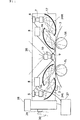
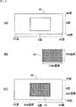
ウェアラブルディスプレイとしては図16(a)に示すような視界の一部に小さいハーフミラー40を配置し、プラズマディスプレイや液晶等の画像出力素子39から出力された画像を、投影光学系38を介して前記ハーフミラー40により偏向し、眼球の網膜に投影する方法が知られている。この方法はハーフミラーを用いているので、視界の一部に画像出力素子39から出力された画像が浮かんで見えるような方式(第1タイプ)である。しかし、視界角度としては数度程度しか得られないので、携帯電話の画面情報の提示等が使用候補としてある。
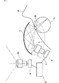
一方、もう少し大きい画像情報を得る手法としては、図16(b)に示すようなものがある。これは、眼球の手前に大きな光学素子41を配置し、複数の反射面及び投影光学系42を介して、画像出力素子39から出力された画像を眼球の網膜に投影するものである。このようなタイプでは、比較的大きな視界角度(15〜30度程度)が得られるが、視界を完全に遮るタイプのものしか提案されていない。従って、使用方法として、片方の眼の前に脱着可能なように設置し、ウェアラブルパソコンとしてのディスプレイに用いる方式のもの(第2タイプ)か、両眼に独立に同画像表示装置を設置して、テレビやプロジェクターの代わりとして使用する方式のもの(第3タイプ)が提案されていた。
上記従来技術による3タイプは、それぞれ携帯電話、ノートパソコン、テレビやプロジェクターに代わるウェアラブルディスプレイとして期待されていた。しかし、実際にはウェアラブルというメリットはあるものの、ディスプレイの視野の大きさでは従来のディスプレイとあまり差がなく、装備するときの面倒や視界を遮られることによる眼の疲れ、耳や頭に搭載する重量等を考えると、デメリットが目立つという欠点があった。
本発明はこのような事情に鑑みてなされたものであり、人間が見る視界に近い、大きな視界角度を有するウェアラブルな、又は目に近接して使用可能な画像表示装置、及び使用者の眼前に配置され、像を使用者の眼球内投影する投影光学系を提供することを目的とする。There are many types of image display devices such as TVs, computers, projectors, video cameras, and mobile phones. However, these conventional image display displays are limited in size and are actually viewed by human eyes. A wide-area image could not be obtained from the display.
Furthermore, as a display that can be carried by a person, a glasses-type display called a wearable display and a head-supported display are known.
As a wearable display, a
On the other hand, as a method for obtaining slightly larger image information, there is a method as shown in FIG. In this method, a large
The above three types according to the prior art have been expected as wearable displays to replace mobile phones, notebook computers, televisions and projectors. However, although there is a merit of wearable in reality, the size of the field of view of the display is not much different from conventional displays, and it is mounted on the ears and head due to the trouble of wearing and obstructing the field of vision when wearing it, Considering the weight and the like, there was a disadvantage that the disadvantages were conspicuous.
The present invention has been made in view of such circumstances, and is a wearable or close-to-eye image display device having a large viewing angle close to the view seen by humans, and in front of the user's eyes. It is an object of the present invention to provide a projection optical system that is arranged and projects an image into a user's eyeball.
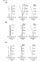
前記目的を達成するための第1の発明は、光束放出方向に直交した表示面を具備する2次元発光型の光電素子と、前記光電素子から放出された光束を使用者の眼球内に投射し、60度以上の視野角を有する魚眼型光学系とを有し、前記眼球の直前に装着される画像表示装置であって、前記魚眼型光学系は、中間像を形成し、前記中間像が形成される位置から前記眼球側に配置された光学素子のうち、前記眼球に最も近い光学素子は、単レンズからなる非球面光学素子であり、当該光学素子の前記眼球から遠い面の面形状は、前記眼球の瞳に入射する前記光束が、当該光学素子の前記眼球から遠い面にほぼ垂直に入射するようなコーニック面からなる非球面形状を有し、かつ当該コーニック面のコーニック係数が−1より小さいことを特徴とする画像表示装置である。
前記目的を達成するための第2の発明は、前記第1の発明であって、画像表示素子を構成する素子のうち、前記眼球側から数えて2番目の光学素子は、単レンズからなり、当該光学素子の眼球から遠い面の面形状は、前記眼球の瞳に入射する前記光束が、当該光学素子の前記眼球から遠い面にほぼ垂直に入射するような形状を有するものであることを特徴とするものである。
前記目的を達成するための第3の発明は、前記第1の発明又は第2の発明であって、前記魚眼型光学系が、リレー光学系を含む第1のレンズ群と、前記第1のレンズ群で形成された前記中間像を前記眼球内に投射する接眼レンズ系とを有していることを特徴とするものである。
前記目的を達成するための第4の発明は、前記第3の発明であって、前記第1のレンズ群が、少なくとも一つ以上の非球面光学素子を有することを特徴とするものである。
前記目的を達成するための第5の発明は、前記第3の発明又は第4の発明であって、前記第1のレンズ群が、テレセン性を補正する曲面ミラーを少なくとも1枚有することを特徴とするものである。
前記目的を達成するための第6の発明は、前記第1の発明から第5の発明のいずれかであって、第1画像情報と、前記第1画像情報とは異なる第2画像情報とを合成し、前記光電素子に合成画像情報を出力する画像合成手段を有することを特徴とするものである。
前記目的を達成するための第7の発明は、前記第6の発明であって、前記画像合成手段が、前記第1画像情報と前記第2画像情報の内少なくとも一方を、前記光電素子から出射した光束が、前記魚眼型光学系により生ずるディストーションを受けた際に、前記使用者に良好な画像が投射できるように、予め前記ディストーションを補正する歪を与える画像処理を行う機能を有することを特徴とするものである。
前記目的を達成するための第8の発明は、前記第6の発明から第8の発明のいずれかであって、前記画像合成手段が、少なくとも第1の画像情報又は第2の画像情報の少なくとも一方とその他の画像とが合成された部分の領域が所定以上の領域に重ならないように前記光電素子へ出力する合成画像情報を制御する画像合成手段制御部を備えたことを特徴とするものである。
前記目的を達成するための第9の発明は、前記第6の発明から第8の発明のいずれかであって、前記第1画像情報と前記第2画像情報の内少なくとも一方は、ビデオ画像、DVD出力及びハイビジョン出力情報のうち少なくとも1つを含むことを特徴とするものである。
前記目的を達成するための第10の発明は、前記第6の発明から第9の発明のいずれかであって、前記第1画像情報と前記第2画像情報の内少なくとも一方は、処理演算手段からの画像出力情報を含むことを特徴とするものである。
前記目的を達成するための第11の発明は、前記第10の発明であって、前記処理演算手段には、前記処理演算手段へ所望の情報を入力するためのキーボードが接続され、前記画像出力情報は、前記キーボードへの入力情報を含むことを特徴とするものである。
前記目的を達成するための第12の発明は、前記第11の発明であって、前記キーボードは、手に取り付けられたポータブルキーボードであることを特徴とするものである。
前記目的を達成するための第13の発明は、前記第12の発明であって、前記ポータブルキーボードは、親指に設置された電磁素子と、その他の指に設置された電磁力検出センサーとを有し、さらに、前記電磁力検出センサーにより検知された電磁場の状態から、その親指とその他の指間の距離、方向情報を認知し、前記距離、方向情報に応じて、特定の符号を与える制御部を有することを特徴とするものである。
前記目的を達成するための第14の発明は、前記第12の発明であって、前記ポータブルキーボードは、各指に設置された圧力検出センサーと、前記圧力検出センサーにより検知された各指の指圧情報を基に、特定の符号を与える制御部と有することを特徴とするものである。
前記目的を達成するための第15の発明は、前記第10の発明であって、前記処理演算手段は、マイク又はヘッドホーンに入力された有声音又は無声音をそれらに対応する特定の符号に変換し、前記特定の符号に対応した画像を前記画像出力情報として出力するものであることを特徴とするものである。
前記目的を達成するための第16の発明は、前記第1の発明から第15の発明のいずれかであって、前記魚眼型光学系が、複数の光電素子から出力された複数の画像を光学的に合成し、前記眼球内の網膜上に複数の画像を投影して結像させる光学的画像合成手段を有することを特徴とするものである。
前記目的を達成するための第17の発明は、前記第16の発明であって、前記光学的画像合成手段は、少なくとも一つの画像に対し可変倍率が2倍以上の光学的ズーム機構を有し、更に、前記一つの画像とその他の画像とが合成された部分の領域が所定以上の領域に重ならないように前記光学的ズーム機構を制御する光学的画像合成手段制御部を備えたことを特徴とするものである。
前記目的を達成するための第18の発明は、前記第1の発明から第17の発明のいずれかの画像表示装置が、それそれ左右眼球に対し別々に配置され、前記使用者の眼球の間隔に応じて各々の前記魚眼型光学系の間隔を調整可能とする調整機構が更に付加されたことを特徴とする両目対応画像表示装置である。
前記目的を達成するための第19の発明は、前記第1の発明から第17の発明のいずれかの画像表示装置であって、一つの前記光電素子から放出された光束を複数に分割する分割光学系を有し、前記分割された光束毎に別々に設置された前記魚眼型光学系を備え、前記使用者の眼球の間隔に応じて各々の魚眼型光学系の間隔を調整可能とする調整機構が更に付加されていることを特徴とする両目対応画像表示装置である。
前記目的を達成するための第20の発明は、前記第1の発明から第17の発明のいずれかの画像表示装置であって、左右眼球に対し、少なくとも一方に配置されることを特徴とするものである。
前記目的を達成するための第21の発明は、前記第1の発明から第17の発明のいずれかの画像表示装置であって、前記光電素子と前記魚眼型光学系をそれぞれ2個有し、当該2個の光電素子が発する各々の光束を左右眼球用に分割すると共に、前記分割された光束のうち異なる光電素子から発せられたものを、左右眼球用にそれぞれ合成する画像分割・合成光学系を有し、さらに、前記画像分割・合成光学系を作動状態と機能停止状態に切り換える切り換え機構を有することを特徴とする両目対応画像表示装置である。
前記目的を達成するための第22の発明は、前記第1の発明から第21の発明のいずれかであって、地震検知センサー、水平計測・調整装置、固定装置の内、少なくとも一つを有することを特徴とするものである。
前記目的を達成するための第23の発明は、前記第1の発明から第22の発明のいずれかであって、タイマー装置、及び当該タイマー装置の出力に応じ、画像表示装置を移動する移動装置が付属されていることを特徴とするものである。
前記目的を達成するための第24の発明は、前記第1の発明から第23の発明のいずれかであって、前記中間像から前記眼球へ伝搬する光束の、前記中間像からの発散角は、前記眼球の横シフトよって前記眼球の瞳位置が変化した場合に、前記眼球の瞳の中心を通る全ての主光線の前記中間像形成面への入射角度の変化範囲よりも、大きい角度を有することを特徴とするものである。
前記目的を達成するための第25の発明は、前記第1の発明から第24の発明のいずれかであって、前記中間像が形成される位置又はその近傍に光を拡散する光拡散体を有することを特徴とするものである。
前記目的を達成するための第26の発明は、前記第25の発明であって、前記光拡散体が、ミクロングレードで粒径が管理された、金属酸化物又は金属炭化物の粒体を、透過板上にコーティングした透過型拡散板であることを特徴とするものである。
前記目的を達成するための第27の発明は、前記第26の発明であって、前記粒体はシリコンカーバイド、酸化クロム、酸化スズ、酸化チタン、酸化マグネシウム、酸化アルミニウムの少なくとも一つであり、前記透過型光拡散板はポリエステルフィルムであることを特徴とするものである。
前記目的を達成するための第28の発明は、前記第1の発明から第27の発明のいずれかであって、当該画像表示装置の一部が使用者の顔面に当接可能であり、更に、少なくとも前記光電素子と前記魚眼型光学系が使用者以外の支持機構により支持され、かつ前記支持機構は使用者顔面の動きに応じて前記光電素子と前記魚眼型光学系を含むユニットを移動可能に支持するものであることを特徴とするものである。
前記目的を達成するための第29の発明は、前記第28の発明であって、前記支持機構が、6軸方向に任意に変位可能であることを特徴とするものである。
前記目的を達成するための第30の発明は、前記第28の発明又は第30の発明であって、その重心位置又はその近傍を、前記支持機構により支持されていることを特徴とするものである。
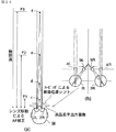
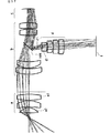
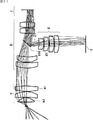
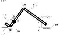
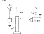
前記目的を達成するための第31の発明は、前記第28の発明から第30の発明のいずれかであって、前記支持機構が、複数の関節部と、錘部と、前記魚眼型光学系と前記光電素子を含む前記ユニットと前記錘部とを結合する柔軟性に富む連結部材と、前記関節部に設けられ、前記連結部材を保持する保持部材とを有し、前記保持部材は前記連結部材の移動に対して発生する抵抗が少ないことを特徴とするものである。
前記目的を達成するための第32の発明は、前記第1の発明から第31の発明のいずれかであって、風景が流れるように移動する画像を検出し、同画像が所定の時間静止して見えるように加工するVE酔い低減手段を備えたことを特徴とするものである。
前記目的を達成するための第33の発明は、前記第32の発明であって、前記VE酔い低減手段の使用、不使用を選択するVE酔い機能選択手段を有することを特徴とするものである。
前記目的を達成するための第34の発明は、前記第32の発明又は第33の発明であって、前記VE酔い低減手段は、前記画像を周辺画像区画と中心面像区画に分け、各区画内にある像の所定時間内の横シフト量を算出し、周辺画像区画の像と中心画像区画の像が同じ方向にシフトしている場合は手ぶれ又は画面の横移動と判断して、所定の時間、画像が横に移動しないように、前記画像全体を像の動いている方向と反対方向に、動き量と同一量シフトさせ、画面全体が静止しているように見える画像に加工することを特徴とするものである。
前記目的を達成するための第35の発明は、使用者の眼前に配置され、像を使用者の眼球内に投影する投影光学系であって、60度以上の画角を有するものにおいて、当該投影光学系を構成する光学素子のうち、前記眼球に最も近い光学素子は、単レンズからなる非球面光学素子であり、当該光学素子の前記眼球から遠い面の面形状は、前記眼球の瞳に入射する前記光束が、当該光学素子の前記眼球から遠い面にほぼ垂直に入射するようなコーニック面からなる非球面形状を有し、かつ当該コーニック面のコーニック係数が−1より小さいことを特徴とする投影光学系である。
前記課題を解決するための第36の発明は、前記第35の発明であって、投影光学系を構成する素子のうち、前記眼球側から数えて2番目の光学素子は、単レンズからなり、当該光学素子の眼球から遠い面の面形状は、前記眼球の瞳に入射する前記光束が、当該光学素子の前記眼球から遠い面にほぼ垂直に入射するような形状を有するものであることを特徴とするものである。
前記目的を達成するための第37の発明は、前記第35の発明であって、前記非球面光学素子は、最も前記眼球に近い位置に配置されていることを特徴とするものである。
前記目的を達成するための第38の発明は、前記第35の発明から第37の発明のいずれかであって、前記像から前記眼球へ伝搬する光束の、前記像からの発散角は、前記眼球の横シフトよって前記眼球の瞳位置が変化した場合に、前記眼球の瞳の中心を通る全ての主光線の前記像面への入射角度の変化範囲よりも、大きい角度を有することを特徴とするものである。
前記課題を解決するための第39の発明は、光束放出方向に直交した表示面を具備する2次元発光型の光電素子と、前記光電素子から放出された光束を使用者の眼球内に投射し、60度以上の視野角を有する魚眼型光学系とを有し、前記眼球の直前に装着される画像表示装置であって、前記魚眼型光学系は、中間像を形成するものであり、前記中間像の形成位置又はその近傍に光拡散体が設けられ、前記中間像が形成される位置から前記眼球側に配置された光学素子のうち、少なくとも1個が、少なくとも一方の面がコーニック面からなる非球面形状を有する非球面光学素子であり、かつ、少なくとも前記魚眼光学系と前記光電素子を、使用者の動きに追従するように、移動可能に支持する支持機構を有することを特徴とする画像表示装置である。
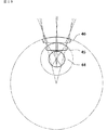
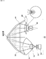
前記目的を達成するための第40の発明は、画像データを出力する光電素子を有し、当該光電素子の出力像を少なくとも2つの曲面形状の反射面を介して眼球内の網膜上に投影する画像表示装置であって、眼球に入射する前に光束を偏向する第1の曲面形状の反射面は第1楕円ミラーであり、当該第1楕円ミラーの第1焦点は、眼球の水晶体近傍に位置し、第2焦点は、前記第1楕円ミラーと第2の曲面形状の反射面の間に位置し、且つ、前記第1焦点と前記第2焦点を結ぶ線の中心を通りこの線に直交する平面と前記第1楕円ミラーの反射面が交差するようにされていることを特徴とする画像表示装置である。
前記目的を達成するための第41の発明は、前記第40の発明であって、前記第2曲面形状の反射面が第2の楕円ミラーであり、当該記第2の楕円ミラーを含む補正光学系により、前記光電素子上の像が眼球内の網膜上に投影されるようにされていることを特徴とするものである。
前記目的を達成するための第42の発明は、前記第40の発明又は第39の発明であって、前記第2曲面形状の反射面が第2の楕円ミラーであり、前記第1楕円ミラーの第2焦点と前記第2楕円ミラーの第1焦点位置がほぼ一致するように配置され、且つ、前記第2楕円ミラーの第1焦点と第2焦点を結ぶ線の中心を通りこの線に直交する平面と前記第2楕円ミラーの反射面が交差するようにされていることを特徴とするものである。
前記目的を達成するための第43の発明は、前記第42の発明であって、前記第1楕円ミラーの第1焦点及び第2焦点、並びに前記第2楕円ミラーの第1焦点及び第2焦点が、ほぼ一直線上に並ぶように配置されていることを特徴とするものである。
前記目的を達成するための第44の発明は前記第42の発明であって、前記第2楕円ミラーと前記光電素子の間の光路中に魚眼型光学系を配置したことを特徴とするものである。
前記目的を達成するための第45の発明は、前記第44の発明であって、前記魚眼型光学系が、眼球の回転に応じた水晶体の移動による網膜の画像検出範囲に、画像データを含む光束を供給する機能を有することを特徴とするものである。
前記目的を達成するための第46の発明は、前記第42の発明から第45の発明のいずれかであって、前記第1楕円ミラーの第2焦点と前記第2楕円ミラーの第1焦点をほぼ一致させた部分に光軸方向の結像位置を補正する補正光学系を配置したことを特徴とするものである。
前記目的を達成するための第47の発明は、前記第40の発明から第46の発明のいずれかであって、前記第1楕円ミラーと前記第2楕円ミラーの曲率が、ほぼ同じであることを特徴するものである。
前記目的を達成するための第48の発明は、前記第40の発明から第47の発明のいずれかの画像表示装置が、左右眼球に対し、少なくとも一方に配置されるように構成されていることを特徴とする画像表示装置である。
前記目的を達成するための第49の発明は、前記第40の発明から第47の発明のいずれかの画像表示装置2個からなり、当該2個の画像表示装置はそれぞれ左右眼球に対し別々に配置され、眼球の間隔に応じて位置が調整可能とされていることを特徴とする画像表示装置。
前記目的を達成するための第50の発明は、前記第40の発明から第49の発明のいずれかであって、前記光電素子が、光束放出方向に直交した2次元発光型の液晶画面であることを特徴とするものである。
前記目的を達成するための第51の発明は、所定の広域像を光束受光方向に直交した2次元受光型の第1光電素子上に投影する第1の魚眼型光学系を有し、前記第1光電素子で受光した画像データを、光束放出方向に直交した2次元発光型の第2光電素子から出力し、当該第2光電素子の出力像を、第2の魚眼型光学系と、曲面形状の反射面を介して眼球内の網膜上に投影する光学系を有することを特徴とする画像表示装置である。
前記目的を達成するための第52の発明は、前記第51の発明であって、前記第2の魚眼型光学系が、眼球の回転に応じた水晶体の移動による網膜の画像検出範囲に、画像データを含む光束を供給する機能を有することを特徴とするものである。
前記目的を達成するための第53の発明は、前記第51の発明又は第52の発明であって、前記曲面形状の反射面は、眼球内の網膜上とほぼ共役な位置に配置され、かつ、前記第2の魚眼型光学系により発生するテレセン性の悪化を補正する曲面とされていることを特徴とするものである。
前記目的を達成するための第54の発明は、前記第51の発明又は第52の発明であって、前記曲面形状の反射面は、眼球内の網膜上とほぼ共役な位置に配置され、かつ、前記第2の魚眼型光学系により発生するテレセン性の悪化を補正する曲面とされていることを特徴とするものである。
前記目的を達成するための第55の発明は、前記第51の発明から第54の発明のいずれかであって、前記曲面形状の反射面は、少なくとも2面のfθ型ミラーで形成されており、かつ、両fθミラーの光軸は互いに平行とされており、一方のfθ型ミラーの焦点が、眼球の水晶体近傍に配置され、他方のfθ型ミラーの焦点が、第2の魚眼型光学系の近傍に配置されていることを特徴とするものである。
前記目的を達成するための第56の発明は、前記第51の発明から第54の発明のいずれかであって、前記曲面形状の反射面は少なくとも2面のfθ型ミラーで形成されており、かつ、両fθミラーの光軸は互いに平行とされており、一方のfθ型ミラーの焦点を、第3の魚眼型光学系を用いて眼球の水晶体近傍にリレーし、他方のfθ型ミラーの焦点を、前記第2の魚眼型光学系を用いて前記第2光電素子近傍にリレーする機能を有することを特徴とするものである。
前記目的を達成するための第57の発明は、前記第51の発明から第53の発明のいずれかであって、前記曲面形状の反射面は少なくとも2面の楕円型ミラーで形成されており、これら2面の楕円型ミラーのそれぞれの2焦点の内、一方がほぼ同じ位置に配置され、全焦点がほぼ一直線上に配置されていることを特徴とするものである。
前記目的を達成するための第58の発明は、前記第51の発明から第57の発明のいずれかの画像表示装置2個からなり、当該2個の画像表示装置はそれぞれ左右眼球に対し別々に配置され、これら2個の画像表示装置の前記第1の魚眼型光学系同士の間隔と眼球の間隔が等しくなるように、左右の眼の間隔に合わせてこれら2個の両画像表示装置の間隔が調整可能とされていることを特徴とする画像表示装置である。
前記目的を達成するための第59の発明は、前記第51の発明から第57の発明のいずれかであって、画像表示装置が、画像表示装置が、左右眼球に対し、少なくとも一方に配置されるように構成されていることを特徴とする画像表示装置である。
前記目的を達成するための第60の発明は、前記第40の発明から第57の発明のいずれかの画像表示装置2個からなり、当該2個の画像表示装置はそれぞれ左右眼球に対し別々に配置され、眼球の間隔に応じて位置が調整可能とされていることを特徴とする画像表示装置である。
前記目的を達成するための第61の発明は、前記第51の発明から第60の発明のいずれかであって、前記第2光電素子が、2次元発光型の液晶装置であることを特徴とするものである。
前記目的を達成するための第62の発明は、前記第51の発明から第61の発明のいずれかであって、前記第1光電素子が、2次元受光型のイメージセンサであることを特徴とするものである。
前記目的を達成するための第63の発明は、所定の広域像を光束受光方向に直交した2次元球面受光型の第1光電素子上に投影し、前記第1光電素子で受光した画像データを、光束放出方向に直交した2次元球面発光型の第2光電素子から出力し、曲面形状の反射面を介して眼球内の網膜上に投影する機能を有することを特徴とする画像表示装置である。
前記目的を達成するための第64の発明は、前記第63の発明であって、前記第1光電素子が、球面上に設けられた凸レンズと、前記球面上に設けられたイメージセンサを有し、前記第2光電素子が、球面上に設けられた凸レンズと、前記球面上に設けられた表示装置を有することを特徴とするものである。
前記目的を達成するための第65の発明は、所定の広域像を光束受光方向に直交した2次元受光型の第1光電素子上に投影する第1の魚眼型光学系を有し、前記第1光電素子で受光した画像データを、光束放出方向に直交した2次元発光型の第2光電素子から出力し、当該第2光電素子の出力像を第2の魚眼型光学系を介して眼球内の網膜上に投影する際に所望の制御を行う制御機構を有することを特徴する画像表示装置である。
前記目的を達成するための第66の発明は、前記第65の発明であって、前記第2の魚眼型光学系が、眼球の回転に応じた水晶体の移動による網膜の画像検出範囲に、画像データを含む光束を供給する機能を有することを特徴とするものである。
前記目的を達成するための第67の発明は、前記第65の発明又は第66の発明であって、前記第2の魚眼型光学系の中に、さらに、曲面形状の反射面を有し、当該曲面形状の反射面は、眼球内の網膜上とほぼ共役な位置に配置され、かつ、前記第2の魚眼型光学系により発生する像面湾曲を補正する曲面とされていることを特徴とするものである。
前記目的を達成するための第68の発明は、前記第65の発明又は第66の発明であって、前記第2の魚眼型光学系中の、眼球内の網膜上とほぼ共役な位置に配置され、かつ、前記第2の魚眼型光学系により発生するテレセン性の悪化を補正する曲面形状の反射面を有することを特徴とするものである。
前記目的を達成するための第69の発明は、前記第65の発明から第68の発明のいずれかであって、少なくとも2面のfθ型ミラーを更に有し、かつ、両fθミラーの光軸は互いに平行とされており、一方のfθ型ミラーの焦点が眼球の水晶体近傍に配置され、他方のfθ型ミラーの焦点が第2の魚眼型光学系の近傍に配置されていることを特徴とするものである。
前記目的を達成するための第70の発明は、前記第65の発明から第68の発明のいずれかであって、前記第2光学系と眼球内の網膜の間に、さらに偏向ミラーを有し、前記偏向ミラーは少なくとも2面のfθ型ミラーで形成されており、かつ、両fθミラーの光軸は互いに平行とされており、一方のfθ型ミラーの焦点を、第3の魚眼型光学系を用いて眼球の水晶体近傍にリレーし、他方のfθ型ミラーの焦点を、前記第2の魚眼型光学系を用いて前記第2光電素子近傍にリレーする機能を有することを特徴とするものである。
前記目的を達成するための第71の発明は、前記第65発明から第68の発明のいずれかであって、前記偏向ミラーは少なくとも2面の楕円型ミラーで形成されており、これら2面の楕円型ミラーのそれぞれの2焦点の内、一方がほぼ同じ位置に配置され、全焦点がほぼ一直線上に配置されていることを特徴とするものである。
前記目的を達成するための第72の発明は、前記第65の発明から第71の発明のいずれかであって、前記制御機構が、前記所定の広域像を合焦するためのフォーカス調整機構、広域像の出力範囲を任意に制御する機構の少なくとも一方を含むことを特徴とするものである。
前記目的を達成するための第73の発明は、前記第65の発明から第72の発明のいずれかであって、前記制御機構が、画像表示装置以外の外部から入力された第1画像情報を、前記第1光電素子から入力された第2画像情報と合成し、前記第2光電素子から出力する画像合成装置を有することを特徴とするものである。
前記目的を達成するための第74の発明は、前記第73の発明であって、前記画像合成装置が、前記第1画像情報を、前記第1の魚眼型光学系により発生したディストーション情報に基づき補正し、前記第2画像情報と合成する機能を有することを特徴とするものである。
前記目的を達成するための第75の発明は、前記第73の発明又は第74の発明であって、前記第1画像情報がビデオ画像出力情報を含むことを特徴するものである。
前記目的を達成するための第76の発明は、前記第75の発明であって、前記ビデオ画像出力情報を供給するビデオ画像入力装置が、前記画像表示装置に着脱可能に固定されていることを特徴とするものである。
前記目的を達成するための第77の発明は、前記第73の発明から第76の発明のいずれかであって、前記第1画像情報が、コンピュータの画像出力情報を含むことを特徴とするものである。
前記目的を達成するための第78の発明は、前記第73の発明から第77の発明のいずれかであって、前記第1画像情報が、コンピュータのキーボード入力情報を含むことを特徴とするものである。
前記目的を達成するための第79の発明は、前記第73の発明から第78の発明のいずれかであって、前記第1画像情報が、手に取り付けられたポータブルキーボード入力情報を含むことを特徴とするものである。
前記目的を達成するための第80の発明は、前記第79の発明であって、前記ポータブルキーボード入力情報が、親指に設置された電磁素子情報を、その他の指に設置された電磁力検出センサーにより検知し、その親指とその他の指間の距離・方向情報に変換することにより得られた画像情報を含むことを特徴とするものである。
前記目的を達成するための第81の発明は、前記第79の発明又は第80の発明であって、前記ポータブルキーボード入力情報が、物体への各指圧情報を各指に設置された圧力検出センサーにより検知し、各指の指圧情報を画像として認識可能な情報に変換することにより得られた画像情報を含むことを特徴とするものである。
前記目的を達成するための第82の発明は、前記第73の発明から第81の発明のいずれかであって、前記第1画像情報が、マイク又はヘッドホーンから入力された有声音又は無声音を文字に変換し、画像情報としたものを含むことを特徴とするものである。
前記目的を達成するための第83の発明は、前記第63の発明から第82の発明のいずれかの画像表示装置2個からなり、当該2個の画像表示装置はそれぞれ左右眼球に対し別々に配置され、これら2個の画像表示装置の前記第1の魚眼型光学系同士の間隔と眼球の間隔が等しくなるように、左右の眼の間隔に合わせてこれら2個の両画像表示装置の間隔が調整可能とされていることを特徴とする画像表示装置である。
前記目的を達成するための第84の発明は、前記第63の発明から第82の発明のいずれかの画像表示装置が、画像表示装置が、左右眼球に対し、少なくとも一方に配置されるように構成されていることを特徴とするものである。
前記目的を達成するための第85の発明は、前記第63の発明から第83の発明のいずれかの画像表示装置2個からなり、当該2個の画像表示装置はそれぞれ左右眼球に対し別々に配置され、眼球の間隔に応じて位置が調整可能とされていることを特徴とする画像表示装置である。
前記目的を達成するための第86の発明は、前記第63の発明から第85の発明のいずれかであって、少なくとも前記第2光電素子が、左右眼球に対し別々に配置され、前記第1光電素子及び前記第1の魚眼型光学系は、左右眼球用に共有されていることを特徴とするものである。
前記目的を達成するための第87の発明は、前記第86の発明であって、前記第1光電素子への入力情報は両眼の幅に応じて位置変換され、前記左右の眼の第2光学素子に、それぞれに対応した別々の情報として出力されることを特徴とするものである。
前記目的を達成するための第88の発明は、光束放出方向に直交した2次元発光型の第1光電素子から放出された光を、前記第1の魚眼型光学系と曲面形状の反射面を介して、眼球内の網膜上に投影して結像させることにより形成される、前記第1光電光学素子の出力像を制御する制御機構を有することを特徴とする画像表示装置である。
前記目的を達成するための第89の発明は、前記第88の発明であって、前記第1の魚眼型光学系が、眼球の回転に応じた水晶体の移動による網膜の画像検出範囲に、画像データを含む光束を供給する機能を有することを特徴とするものである。
前記目的を達成するための第90の発明は、前記第88の発明又は第89の発明であって、前記曲面形状の反射面は、眼球内の網膜上とほぼ共役な位置に配置され、かつ、前記第1の魚眼型光学系により発生する像面湾曲を補正する曲面であることを特徴とするものである。
前記目的を達成するための第91の発明は、前記第88の発明又は第89の発明であって、前記曲面形状の反射面は、眼球内の網膜上とほぼ共役な位置に配置され、かつ、前記第1の魚眼型光学系により発生するテレセン性の悪化を補正する曲面であることを特徴とするものである。
前記目的を達成するための第92の発明は、前記第90の発明又は第91の発明であって、少なくとも2面のfθ型ミラーを更に有し、かつ、両fθミラーの光軸は互いに平行とされており、一方のfθ型ミラーの焦点が眼球の水晶体近傍に配置され、他方のfθ型ミラーの焦点が第1の魚眼型光学系の近傍に配置されている偏向ミラーを有することを特徴とするものである。
前記目的を達成するための第93の発明は、前記第88の発明から第91の発明のいずれかであって、前記第1の魚眼型光学系と眼球内の網膜の間に、さらに偏向ミラーを有し、前記偏向ミラーは少なくとも2面のfθ型ミラーで形成されており、かつ、両fθミラーの光軸は互いに平行とされており、一方のfθ型ミラーの焦点を、第3の魚眼型光学系を用いて眼球の水晶体近傍にリレーし、他方のfθ型ミラーの焦点を、前記第2の魚眼型光学系を用いて前記第1光電素子近傍にリレーする機能を有することを特徴とするものである。
前記目的を達成するための第94の発明は、前記第88の発明から第91の発明のいずれかであって、前記第1の魚眼型光学系と眼球内の網膜の間に、さらに偏向ミラーを有し、前記偏向ミラーは少なくとも2面の楕円型ミラーで形成されており、これら2面の楕円型ミラーのそれぞれの2焦点の内、一方がほぼ同じ位置に配置され、全焦点がほぼ一直線上に配置されていることを特徴とするものである。
前記目的を達成するための第95の発明は、前記第88の発明から第94の発明のいずれかであって、前記制御機構が、前記所定の広域像を合焦するためのフォーカス調整機構、広域像の出力範囲を任意に制御する機構の少なくとも一方を含むことを特徴とするものである。
前記目的を達成するための第96の発明は、前記第88の発明から第95の発明のいずれかであって、前記制御機構が、第1画像情報と、前記第1画像情報とは異なる第2画像情報とを合成し、前記第1光電素子から出力する画像合成機能を有することを特徴とするものである。
前記目的を達成するための第97の発明は、前記第88の発明から第95の発明のいずれかであって、前記制御機構が、前記第1光電素子から出力された第1画像情報と、前記第2光電素子から出力された第2画像情報とを光学的に合成し、前記眼球内の網膜上に投影して結像させる機能を有することを特徴とするものである。
前記目的を達成するための第98の発明は、前記第96の発明又は第97の発明であって、前前記制御機構が、前記第1画像情報と前記第2画像情報の内少なくとも一方を、前記第1の魚眼型光学系により発生したディストーション情報に基づき補正し、その後、これらの画像情報を合成することを特徴とするものである。
前記目的を達成するための第99の発明は、前記第95の発明から第98の発明のいずれかであって、前記第1画像情報と前記第2画像情報の内少なくとも一方は、ビデオ画像、DVD及びハイビジョン出力情報情報のうち少なくとも1つを含むことを特徴とするものである。
前記目的を達成するための第100の発明は、前記第95の発明から第99の発明のいずれかであって、前記第1画像情報と前記第2画像情報の内少なくとも一方は、コンピュータの画像出力情報を含むことを特徴とするものである。
前記目的を達成するための第101の発明は、前記第95の発明から第100の発明のいずれかであって、前記第1画像情報と前記第2画像情報の内少なくとも一方は、コンピュータのキーボード入力情報を含むことを特徴とするものである。
前記目的を達成するための第102の発明は、前記第95の発明から第101の発明のいずれかであって、前記第1画像情報と前記第2画像情報の内少なくとも一方は、手に取り付けられたポータブルキーボード入力情報を含むことを特徴とするものである。
前記目的を達成するための第103の発明は、前記第102の発明であって、前記ポータブルキーボード入力情報は、親指に設置された電磁素子情報を、その他の指に設置された電磁力検出センサーにより検知し、その親指とその他の指間の距離・方向情報に変換することにより得られた画像情報を含むことを特徴とするものである。
前記目的を達成するための第104の発明は、前記第102の発明又は第103の発明であって、前記ポータブルキーボード入力情報が、物体への各指圧情報を各指に設置された圧力検出センサーにより検知し、各指の指圧情報を画像として認識可能な情報に変換することにより得られた画像情報を含むことを特徴とするものである。
前記目的を達成するための第105の発明は、前記第95の発明から第104の発明のいずれかであって、前記第1画像情報及び、前記第2画像情報の内少なくとも一方は、マイク又はヘッドホーンから入力された有声音又は無声音を文字に変換し、画像情報としたものを含むことを特徴とするものである。
前記目的を達成するための第106の発明は、前記第88の発明から第105の発明のいずれかの画像表示装置2個からなり、当該2個の画像表示装置はそれぞれ左右眼球に対し別々に配置され、これら2個の画像表示装置の前記第1の魚眼型光学系同士の間隔と眼球の間隔が等しくなるように、左右の眼の間隔に合わせてこれら2個の両画像表示装置の間隔が調整可能とされていることを特徴とする画像表示装置である。
前記目的を達成するための第107の発明は、前記第88の発明から第105の発明のいずれかの画像表示装置が、画像表示装置が、左右眼球に対し、少なくとも一方に配置されるように構成されていることを特徴とする画像表示装置である。
前記目的を達成するための第108の発明は、光束放出方向に直交した2次元発光型の第1光電素子から放出された光を、リレー光学系を含んだ第1の魚眼型光学系を介して眼球内の網膜上に投影して結像させることにより形成される前記第1光電光学素子の出力像を制御する制御機構を有し、当該制御機構は所定の広域像を合焦するためのフォーカス調整機構、当該広域像の出力範囲を任意に制御する機構の少なくとも一方を含み、前記広域像の視野角は60°以上であることを特徴とする画像表示装置である。
前記目的を達成するための第109の発明は、前記第108の発明であって、前記第1の魚眼型光学系が、眼球の回転に応じた水晶体の移動による網膜の画像検出範囲に、画像データを含む光束を供給する機能を有することを特徴とするものである。
前記目的を達成するための第110の発明は、前記第108の発明又は第109の発明であって、前記第1の魚眼型光学系が、双曲面レンズ又は回転対称2次曲面レンズを少なくとも1枚有することを特徴とするものである。
前記目的を達成するための第111の発明は、前記第108の発明から第110の発明のいずれかであって、前記リレー光学系が、双曲面レンズ又は回転対称2次曲面レンズを少なくとも1枚有することを特徴とするものである。
前記目的を達成するための第112の発明は、前記第111の発明であって、前記リレー光学系の双曲面レンズ又は回転対称2次曲面レンズが、瞳位置近傍に配置されていることを特徴とするものである。
前記目的を達成するための第113の発明は、前記第108の発明から第112の発明のいずれかであって、前記リレー光学系が、テレセン性を補正する曲面ミラーを少なくとも1枚有することを特徴とするものである。
前記目的を達成するための第114の発明は、前記第108の発明から第113の発明のいずれかの画像表示装置が、画像表示装置が、左右眼球に対し、少なくとも一方に配置されるように構成されていることを特徴とする画像表示装置である。
前記目的を達成するための第115の発明は、前記第108の発明から第114の発明のいずれかであって、前記制御機構が、第1画像情報と、前記第1画像情報とは異なる第2画像情報とを合成し、前記第1光電素子から出力する画像合成機能を有することを特徴とするものである。
前記目的を達成するための第116の発明は、前記第107の発明から第115の発明のいずれかであって、前記制御機構が、前記第1光電素子から出力された第1画像情報と、前記第2光電素子から出力された第2画像情報とを光学的に合成し、前記眼球内の網膜上に投影して結像させる機能を有することを特徴とするものである。
前記目的を達成するための第117の発明は、前記第115の発明又は第116の発明であって、前記制御機構が、前記第1画像情報と前記第2画像情報の内少なくとも一方を、前記第1の魚眼型光学系により発生したディストーション情報に基づき補正し、その後、これらの画像情報を合成することを特徴とするものである。
前記目的を達成するための第118の発明は、前記第115の発明から第117の発明のいずれかであって、前記第1画像情報と前記第2画像情報の内少なくとも一方は、ビデオ画像、DVD出力及びハイビジョン出力情報のうち少なくとも1つを特徴とするものである。
前記目的を達成するための第119の発明は、前記第115の発明から第118の発明のいずれかであって、前記第1画像情報と前記第2画像情報の内少なくとも一方は、コンピュータの画像出力情報を含むことを特徴とするものである。
前記目的を達成するための第120の発明は、前記第115の発明から第119の発明のいずれかであって、前記第1画像情報と前記第2画像情報の内少なくとも一方は、コンピュータのキーボード入力情報を含むことを特徴とするものである。
前記目的を達成するための第121の発明は、前記第115の発明から第120の発明のいずれかであって、前記第1画像情報と前記第2画像情報の内少なくとも一方は、手に取り付けられたポータブルキーボード入力情報を含むことを特徴とするものである。
前記目的を達成するための第122の発明は、前記第121の発明であって、前記ポータブルキーボード入力情報は、親指に設置された電磁素子情報を、その他の指に設置された電磁力検出センサーにより検知し、その親指とその他の指間の距離・方向情報に変換することにより得られた画像情報を含むことを特徴とするものである。
前記目的を達成するための第123の発明は、前記第121の発明又は第120の発明であって、前記ポータブルキーボード入力情報が、物体への各指圧情報を各指に設置された圧力検出センサーにより検知し、各指の指圧情報を画像として認識可能な情報に変換することにより得られた画像情報を含むことを特徴とするものである。
前記目的を達成するための第124の発明は、前記第115の発明から第123の発明のいずれかであって、前記第1画像情報及び、前記第2画像情報の内少なくとも一方は、マイク又はヘッドホーンから入力された有声音又は無声音を文字に変換し、画像情報としたものを含むことを特徴とするものである。
前記目的を達成するための第125の発明は、前記第115の発明から第124の発明のいずれかの画像表示装置2個からなり、当該2個の画像表示装置はそれぞれ左右眼球に対し別々に配置され、これら2個の画像表示装置の前記第1魚眼型光学系同士の間隔と眼球の間隔が等しくなるように、左右の眼の間隔に合わせてこれら2個の両画像表示装置の間隔が調整可能とされていることを特徴とするものである。
前記目的を達成するための第126の発明は、前記第115の発明から第124の発明のいずれかの画像表示装置1個からなり、当該1個の画像表示装置はそれぞれ左右眼球に対し光学部材により分割され、分割された光束に別々に設置された前記第1魚眼型光学系同士の間隔と眼球の間隔が等しくなるように、左右の眼の間隔に合わせて各々の前記第1の魚眼型光学系の投影像の間隔が調整可能とされていることを特徴とするものである。
前記目的を達成するための第127の発明は、前記第108の発明から第126の発明のいずれかであって、前記画像データを出力する光電素子と、水晶体との光路中に設けられた結像面に配置され、光を拡散する光拡散体を有し、前記第1の魚眼型光学系の少なくとも一部の光学系は、拡散した透過光を水晶体近傍に集光させ、網膜上に物面の像を結像させることを特徴とするものである。
前記目的を達成するための第128の発明は、前記第127の発明であって、前記光を拡散する光拡散体は金属酸化物や金属炭化物のミクロングレードで精密に粒径が管理された砥粒を透過板上にコーティングした透過型拡散板であることを特徴とするものである。
前記目的を達成するための第129の発明は、前記第128の発明であって、前記砥粒はシリコンカーバイド、酸化クロム、酸化スズ、酸化チタン、酸化マグネシウム、酸化アルミニウムの少なくとも一つであり、前記透過板はポリエステルフィルムであることを特徴とするものである。
前記目的を達成するための第130の発明は、前記第40の発明から第129の発明のいずれかであって、前記画像表示装置の少なくとも一部が、使用者以外の部分に支持されており、使用者顔面にも接触し、使用者顔面の動きに応じて移動可能とされていることを特徴とするものである。
前記目的を達成するための第131の発明は、前記第130の発明であって、前記画像表示装置の少なくとも一部は、6軸方向に任意に駆動可能とされていることを特徴とするものである。
前記目的を達成するための第132の発明は、前記第131の発明であって、前記6軸方向に任意に駆動可能とする為に、前記画像表示装置本体の重心若しくはその近傍にて支持することを特徴とするものである。
前記目的を達成するための第133の発明は、前記第131の発明又は第132の発明であって、前記6軸方向に任意に駆動可能とする為に、前記画像表示装置本体とバランスさせる錘及び、前記画像表示装置本体と前記錘を結合する糸状に軟性部材及び滑車を有することを特徴とするものである。
前記目的を達成するための第134の発明は、前記第108の発明から第133の発明のいずれかであって、前記当該広域像の出力範囲を任意に制御する機構は可変倍率が2倍以上の光学的ズーム機構であり、ズーム状態に応じて前記第1画像情報と前記第2画像情報で合成された合成画像が所定の幅以上に重ならないように制御することを特徴とするものである。
前記目的を達成するための第135の発明は、前記第108の発明から第134の発明のいずれかであって、前記当該広域像の出力範囲を任意に制御する機構は、観察者の視線上で風景が流れるように移動する画像を検出する検出手段と、同画像を所定の時間画像が横に移動しないように加工し記憶する記憶手段を有することを特徴とするものである。
前記目的を達成するための第136の発明は、前記第108の発明から第135の発明のいずれかであって、前記当該広域像の出力範囲を任意に制御する機構は、前記検出手段及び前記加工し記憶する手段の使用、未使用を任意に選択する選択手段を有することを特徴とするものである。
前記目的を達成するための第137の発明は、前記第135の発明又は第136の発明であって、前記課題を前記検出手段及び記憶手段は、画像データを内部バッファに取り込み、内部バッファから出力した画像を周辺画像と中心画像区画に分け、区画内の所定時間に於ける横シフト量を算出し、同周辺画像と同中心画像が同じ方向にシフトしている場合は手ぶれもしくは画面の横移動と判断して、所定の時間画像が横に移動しないように、画像ビット全体を像の動いている方向と反対方向に動き量と同一量シフトさせ画面全体が静止しているように見える画像に加工することを特徴とするものである。
前記目的を達成するための第138の発明は、前記第115の発明から第124の発明のいずれかの画像表示装置2個からなり、当該2個の画像表示装置はそれぞれ左右眼球に対し画像を分割合成して供給する為の分割合成手段と、それぞれ左右眼球に対し画像を別々に供給する手段を切り換える切り替え手段を有する事を特徴する画像表示装置である。
前記目的を達成するための第139の発明は、前記第130の発明から第133の発明のいずれかであって、前記画像表示装置の一部は少なくとも地震検知センサー、水平計測・調整装置、固定装置の3つの内、少なくとも一つを有することを特徴とするものである。
前記目的を達成するための第140の発明は、前記第130の発明から第133の発明、又は第139の発明であって、前記画像表示装置の一部はタイマー装置及び同タイマー装置の出力に応じ、画像表示部を移動する移動装置を有することを特徴とするものである。A first invention for achieving the above object is to project a two-dimensional light-emitting photoelectric element having a display surface orthogonal to a light beam emission direction and a light beam emitted from the photoelectric element into a user's eyeball. A fish-eye optical system having a viewing angle of 60 degrees or more, and an image display device mounted immediately before the eyeball, wherein the fish-eye optical system forms an intermediate image and the intermediate Of the optical elements arranged on the eyeball side from the position where an image is formed, the optical element closest to the eyeball is an aspherical optical element consisting of a single lens, and the surface of the surface of the optical element far from the eyeball The shape has an aspherical shape formed of a conic surface such that the light beam incident on the pupil of the eyeball is substantially perpendicularly incident on a surface far from the eyeball of the optical element, and the conic coefficient of the conic surface is Characterized by being less than -1. It is an image display device.
The second invention for achieving the above object is the first invention, wherein the second optical element counted from the eyeball side among the elements constituting the image display element comprises a single lens, The surface shape of the surface of the optical element far from the eyeball is such that the light beam incident on the pupil of the eyeball is incident substantially perpendicularly on the surface of the optical element far from the eyeball. It is what.
A third invention for achieving the object is the first invention or the second invention, wherein the fisheye optical system includes a first lens group including a relay optical system, and the first lens group. And an eyepiece system for projecting the intermediate image formed by the lens group into the eyeball.
A fourth invention for achieving the object is the third invention, wherein the first lens group has at least one aspherical optical element.
A fifth invention for achieving the above object is the third invention or the fourth invention, wherein the first lens group has at least one curved mirror for correcting telecentricity. It is what.
A sixth invention for achieving the object is any one of the first to fifth inventions, wherein the first image information and second image information different from the first image information are provided. It has an image synthesizing means for synthesizing and outputting synthesized image information to the photoelectric element.
A seventh invention for achieving the object is the sixth invention, wherein the image synthesizing means emits at least one of the first image information and the second image information from the photoelectric element. And having a function of performing image processing that gives distortion to correct the distortion in advance so that a good image can be projected to the user when the luminous flux is subjected to distortion generated by the fish-eye optical system. It is a feature.
An eighth invention for achieving the object is any one of the sixth to eighth inventions, wherein the image synthesizing means includes at least the first image information or the second image information. An image composition means control unit for controlling composite image information to be output to the photoelectric element so that a region where one image is combined with another image does not overlap a predetermined region or more is provided. is there.
A ninth invention for achieving the object is any one of the sixth to eighth inventions, wherein at least one of the first image information and the second image information is a video image, It includes at least one of DVD output and high-definition output information.
A tenth invention for achieving the object is any one of the sixth invention to the ninth invention, wherein at least one of the first image information and the second image information is a processing operation means. The image output information from is included.
An eleventh invention for achieving the above object is the tenth invention, wherein a keyboard for inputting desired information to the processing calculation means is connected to the processing calculation means, and the image output The information includes information input to the keyboard.
A twelfth aspect of the invention for achieving the object is the eleventh aspect of the invention, wherein the keyboard is a portable keyboard attached to a hand.
A thirteenth invention for achieving the above object is the twelfth invention, wherein the portable keyboard has an electromagnetic element installed on a thumb and an electromagnetic force detection sensor installed on another finger. And a controller that recognizes distance and direction information between the thumb and other fingers from the state of the electromagnetic field detected by the electromagnetic force detection sensor, and gives a specific code according to the distance and direction information. It is characterized by having.
A fourteenth invention for achieving the object is the twelfth invention, wherein the portable keyboard includes a pressure detection sensor installed on each finger, and a finger pressure detected by the pressure detection sensor. It has a control part which gives a specific code based on information.
The fifteenth invention for achieving the object is the tenth invention, wherein the processing calculation means converts voiced sound or unvoiced sound input to a microphone or a headphone into a specific code corresponding thereto. The image corresponding to the specific code is output as the image output information.
A sixteenth invention for achieving the object is any one of the first to fifteenth inventions, wherein the fish-eye optical system outputs a plurality of images output from a plurality of photoelectric elements. Optical image synthesis means for optically synthesizing and projecting a plurality of images on the retina in the eyeball is formed.
A seventeenth invention for achieving the object is the sixteenth invention, wherein the optical image synthesizing means has an optical zoom mechanism having a variable magnification of 2 times or more for at least one image. And an optical image synthesizing means control unit for controlling the optical zoom mechanism so that a region of a portion where the one image and the other image are combined does not overlap a predetermined region or more. It is what.
According to an eighteenth aspect of the invention for achieving the above object, any one of the image display devices according to the first to seventeenth aspects of the present invention is separately arranged with respect to the left and right eyeballs, and the distance between the eyeballs of the user The binocular image display apparatus further includes an adjustment mechanism that can adjust the interval between the fish-eye optical systems according to the above.
A nineteenth invention for achieving the above object is the image display device according to any one of the first to seventeenth inventions, wherein the luminous flux emitted from one photoelectric element is divided into a plurality of parts. An optical system is provided, and the fisheye optical system is provided separately for each of the divided light beams, and the interval between the fisheye optical systems can be adjusted according to the interval between the eyes of the user. An image display device that supports both eyes is further provided with an adjustment mechanism that performs the adjustment.
A twentieth invention for achieving the above object is the image display device according to any one of the first to seventeenth inventions, wherein the image display device is arranged on at least one of the left and right eyeballs. Is.
A twenty-first invention for achieving the above object is the image display device according to any one of the first to seventeenth inventions, each having two photoelectric elements and two fisheye optical systems. Image splitting / synthesizing optics for splitting the light beams emitted by the two photoelectric elements for the left and right eyeballs, and combining the split light beams emitted from different photoelectric elements for the left and right eyeballs, respectively. And a switching mechanism for switching the image dividing / synthesizing optical system between an operating state and a function stop state.
A twenty-second invention for achieving the object is any one of the first to twenty-first inventions, and includes at least one of an earthquake detection sensor, a horizontal measurement / adjustment device, and a fixing device. It is characterized by this.
A twenty-third invention for achieving the object is any one of the first to twenty-second inventions, wherein the timer device and a moving device that moves the image display device according to the output of the timer device are provided. Is attached.
A twenty-fourth invention for achieving the object is any one of the first to twenty-third inventions, wherein a divergence angle of the light beam propagating from the intermediate image to the eyeball is from the intermediate image. When the pupil position of the eyeball is changed by the lateral shift of the eyeball, the angle of incidence is greater than the range of change in the incident angle of all principal rays passing through the center of the pupil of the eyeball to the intermediate image forming surface. It is characterized by this.
A twenty-fifth aspect of the invention for achieving the object is any one of the first to twenty-fourth aspects, wherein a light diffuser that diffuses light at or near a position where the intermediate image is formed. It is characterized by having.
A twenty-sixth aspect of the invention for achieving the object is the twenty-fifth aspect of the invention, wherein the light diffuser transmits a particle of metal oxide or metal carbide whose particle size is controlled in a micron grade. It is a transmissive diffusion plate coated on a plate.
A twenty-seventh aspect of the invention for achieving the above object is the twenty-sixth aspect of the invention, wherein the particles are at least one of silicon carbide, chromium oxide, tin oxide, titanium oxide, magnesium oxide, and aluminum oxide. The transmissive light diffusing plate is a polyester film.
A twenty-eighth aspect of the present invention for achieving the above object is any one of the first to twenty-seventh aspects, wherein a part of the image display device can contact the face of the user. , At least the photoelectric element and the fisheye optical system are supported by a support mechanism other than a user, and the support mechanism includes a unit including the photoelectric element and the fisheye optical system according to the movement of the user's face. It is characterized by being movably supported.
A twenty-ninth aspect of the invention for achieving the above object is the twenty-eighth aspect of the invention, wherein the support mechanism is arbitrarily displaceable in six axial directions.
The thirtieth invention for achieving the object is the twenty-eighth invention or the thirtieth invention, characterized in that the center of gravity position or the vicinity thereof is supported by the support mechanism. is there.
The thirty-first invention for achieving the object is any one of the twenty-eighth to thirty-third inventions, wherein the support mechanism includes a plurality of joint portions, a weight portion, and the fish-eye optical. A flexible connecting member that joins the weight unit and the unit including the system and the photoelectric element, and a holding member that is provided at the joint and holds the connecting member, the holding member being It is characterized in that the resistance generated with respect to the movement of the connecting member is small.
A thirty-second invention for achieving the object is any one of the first to thirty-first inventions, wherein an image moving so as to flow a landscape is detected, and the image is stationary for a predetermined time. It is characterized by having VE sickness reduction means for processing so that it can be seen.
A thirty-third invention for achieving the above object is the thirty-second invention, characterized by comprising VE sickness function selecting means for selecting use or non-use of the VE sickness reducing means. .
A thirty-fourth invention for achieving the object is the thirty-second invention or the thirty-third invention, wherein the VE sickness reducing means divides the image into a peripheral image section and a center plane image section, and The horizontal shift amount within a predetermined time of the image inside is calculated, and when the image of the peripheral image section and the image of the central image section are shifted in the same direction, it is determined that the camera shake or the horizontal movement of the screen The entire image is shifted by the same amount as the amount of movement in the opposite direction to the moving direction of the image so that the image does not move laterally, and the entire screen is processed into an image that appears to be stationary. It is a feature.
A thirty-fifth aspect of the invention for achieving the above object is a projection optical system that is arranged in front of the user's eyes and projects an image into the user's eyeball, and has an angle of view of 60 degrees or more. Of the optical elements constituting the projection optical system, the optical element closest to the eyeball is an aspherical optical element composed of a single lens, and the surface shape of the surface of the optical element far from the eyeball is the pupil of the eyeball. The incident light beam has an aspherical shape formed of a conic surface that is incident substantially perpendicularly to a surface far from the eyeball of the optical element, and the conic coefficient of the conic surface is smaller than −1. Projection optical system.
The thirty-sixth invention for solving the above-mentioned problem is the thirty-fifth invention, wherein the second optical element counted from the eyeball side among the elements constituting the projection optical system comprises a single lens, The surface shape of the surface of the optical element far from the eyeball is such that the light beam incident on the pupil of the eyeball is incident substantially perpendicularly on the surface of the optical element far from the eyeball. It is what.
A thirty-seventh aspect of the invention for attaining the object is the thirty-fifth aspect of the invention, wherein the aspherical optical element is disposed at a position closest to the eyeball.
A thirty-eighth aspect of the present invention for achieving the object is any one of the thirty-fifth to thirty-seventh aspects, wherein a divergence angle of the light beam propagating from the image to the eyeball is from the image. When the pupil position of the eyeball changes due to a lateral shift of the eyeball, it has an angle larger than the change range of the incident angle to the image plane of all principal rays passing through the center of the pupil of the eyeball. To do.
According to a thirty-ninth aspect of the invention for solving the above-described problems, a two-dimensional light-emitting photoelectric element having a display surface orthogonal to a luminous flux emission direction and a luminous flux emitted from the photoelectric element are projected into a user's eyeball. A fish-eye optical system having a viewing angle of 60 degrees or more, and is an image display device mounted immediately before the eyeball, wherein the fish-eye optical system forms an intermediate image. A light diffuser is provided at or near the formation position of the intermediate image, and at least one of the optical elements disposed on the eyeball side from the position where the intermediate image is formed has at least one surface conic. A non-spherical optical element having an aspheric surface shape, and having a support mechanism that movably supports at least the fish-eye optical system and the photoelectric element so as to follow the movement of the user. A characteristic image display device That.
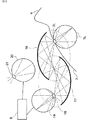
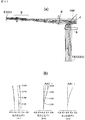
A 40th invention for achieving the above object has a photoelectric element for outputting image data, and projects an output image of the photoelectric element onto a retina in an eyeball through at least two curved reflecting surfaces. In the image display device, the first curved reflecting surface that deflects the light beam before entering the eyeball is a first elliptical mirror, and the first focal point of the first elliptical mirror is located in the vicinity of the crystalline lens of the eyeball. The second focal point is located between the first elliptical mirror and the second curved reflecting surface and passes through the center of the line connecting the first focal point and the second focal point and is orthogonal to the line. An image display device characterized in that a plane and a reflection surface of the first elliptical mirror intersect each other.
A 41st invention for achieving the above object is the 40th invention, wherein the reflecting surface of the second curved surface shape is a second elliptical mirror, and correction optics including the second elliptical mirror. An image on the photoelectric element is projected onto the retina in the eyeball by the system.
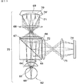
A forty-second invention for achieving the object is the forty-fourth or thirty-ninth invention, wherein the second curved reflecting surface is a second elliptical mirror, and the first elliptical mirror is provided. The second focal point and the second elliptical mirror are arranged so that the first focal point positions thereof substantially coincide with each other, and pass through the center of the line connecting the first and second focal points of the second elliptical mirror and are orthogonal to this line. The flat surface and the reflecting surface of the second elliptical mirror intersect each other.
A forty-third invention for achieving the above object is the forty-second invention, wherein the first and second focal points of the first elliptical mirror and the first and second focal points of the second elliptical mirror are provided. Are arranged so as to be substantially aligned.
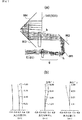
The forty-fourth invention for achieving the above object is the forty-second invention, characterized in that a fish-eye optical system is disposed in an optical path between the second elliptical mirror and the photoelectric element. It is.
A forty-fifth aspect of the invention for achieving the above object is the forty-fourth aspect of the invention, in which the fish-eye type optical system transmits image data to the retina image detection range by movement of the lens according to the rotation of the eyeball. It has a function of supplying a luminous flux including it.
A forty-sixth aspect of the present invention for attaining the object is any one of the forty-second to forty-fifth aspects, wherein the second focal point of the first elliptical mirror and the first focal point of the second elliptical mirror are provided. A correction optical system for correcting the imaging position in the optical axis direction is arranged in the substantially matched portion.
A 47th invention for achieving the above object is any of the 40th to 46th inventions, wherein the curvatures of the first elliptical mirror and the second elliptical mirror are substantially the same. It is a characteristic.
In order to achieve the above object, the forty-eighth aspect of the invention is that the image display device according to any of the forty-fourth to forty-seventh aspects of the invention is arranged so as to be arranged on at least one of the left and right eyeballs. Is an image display device characterized by the above.
A 49th invention for achieving the above object comprises two image display devices according to any one of the 40th to 47th inventions, and the two image display devices are separately provided for the left and right eyeballs, respectively. An image display device, wherein the image display device is arranged and the position can be adjusted according to the interval between eyeballs.
A 50th invention for achieving the object is any one of the 40th to 49th inventions, wherein the photoelectric element is a two-dimensional light emission type liquid crystal screen orthogonal to a light beam emission direction. It is characterized by this.
According to a fifty-first aspect of the present invention, the first fisheye optical system projects a predetermined wide-area image onto a two-dimensional light-receiving first photoelectric element orthogonal to a light beam receiving direction, Image data received by the first photoelectric element is output from a two-dimensional light emitting type second photoelectric element orthogonal to the light beam emission direction, and an output image of the second photoelectric element is output to the second fisheye optical system; An image display apparatus comprising an optical system that projects onto a retina in an eyeball through a curved reflecting surface.
A fifty-second invention for achieving the above object is the fifty-first invention, wherein the second fish-eye optical system has an image detection range of the retina due to movement of the lens according to the rotation of the eyeball. It has a function of supplying a light beam including image data.
The 53rd invention for achieving the above object is the 51st invention or the 52nd invention, wherein the curved reflecting surface is disposed at a position substantially conjugate with the retina in the eyeball, and The curved surface corrects the deterioration of telecentricity generated by the second fish-eye type optical system.
The 54th invention for achieving the above object is the 51st invention or the 52nd invention, wherein the curved reflecting surface is disposed at a position substantially conjugate with the retina in the eyeball, and The curved surface corrects the deterioration of telecentricity generated by the second fish-eye type optical system.
The 55th invention for achieving the above object is any of the 51st to 54th inventions, wherein the curved reflecting surface is formed of at least two fθ-type mirrors. In addition, the optical axes of the two fθ mirrors are parallel to each other, the focal point of one fθ mirror is disposed in the vicinity of the lens of the eyeball, and the focal point of the other fθ mirror is the second fisheye optical. It is arranged in the vicinity of the system.
A fifty-sixth aspect of the present invention for attaining the object is any one of the fifty-first to fifty-fourth aspects, wherein the curved reflecting surface is formed of at least two fθ-type mirrors, The optical axes of both fθ mirrors are parallel to each other, and the focal point of one fθ mirror is relayed to the vicinity of the lens of the eyeball using the third fisheye optical system, and the other fθ mirror is It has a function of relaying the focal point to the vicinity of the second photoelectric element by using the second fisheye type optical system.
The 57th invention for achieving the above object is any one of the 51st to 53rd inventions, wherein the curved reflecting surface is formed of at least two elliptical mirrors, One of the two focal points of the two-plane elliptical mirrors is arranged at substantially the same position, and all the focal points are arranged substantially in a straight line.
A 58th invention for achieving the above object comprises two image display devices according to any of the 51st to 57th inventions, and the two image display devices are separately provided for the left and right eyeballs, respectively. The two image display devices are arranged in accordance with the distance between the left and right eyes so that the distance between the first fish-eye optical systems of these two image display apparatuses and the distance between the eyeballs are equal. The image display device is characterized in that the interval is adjustable.
A fifty-ninth invention for achieving the object is any one of the fifty-first to fifty-seventh inventions, wherein the image display device is disposed on at least one of the right and left eyeballs. An image display device characterized by being configured as described above.
The 60th invention for achieving the object comprises two image display devices according to any of the 40th to 57th inventions, and the two image display devices are separately provided for the left and right eyeballs, respectively. The image display device is characterized in that it is arranged and the position can be adjusted according to the interval between eyeballs.
The 61st invention for achieving the above object is any of the 51st to 60th inventions, characterized in that the second photoelectric element is a two-dimensional light emitting liquid crystal device. To do.
The 62nd invention for achieving the object is any one of the 51st to 61st inventions, characterized in that the first photoelectric element is a two-dimensional light receiving type image sensor. To do.
According to a 63rd aspect of the invention for achieving the above object, a predetermined wide area image is projected onto a first photoelectric element of a two-dimensional spherical light receiving type orthogonal to a light beam receiving direction, and image data received by the first photoelectric element is obtained. An image display device characterized by having a function of outputting from a second photoelectric element of a two-dimensional spherical light emitting type orthogonal to the light beam emission direction and projecting it onto a retina in the eyeball through a curved reflecting surface .
The 64th invention for achieving the above object is the 63rd invention, wherein the first photoelectric element has a convex lens provided on a spherical surface and an image sensor provided on the spherical surface. The second photoelectric element has a convex lens provided on a spherical surface and a display device provided on the spherical surface.
A 65th invention for achieving the above object comprises a first fisheye optical system that projects a predetermined wide-area image onto a first photoelectric element of a two-dimensional light receiving type orthogonal to a light beam receiving direction, Image data received by the first photoelectric element is output from a two-dimensional light emitting type second photoelectric element orthogonal to the light beam emission direction, and an output image of the second photoelectric element is transmitted via the second fisheye optical system. An image display apparatus having a control mechanism for performing desired control when projecting onto a retina in an eyeball.
The 66th invention for achieving the above object is the 65th invention, wherein the second fish-eye optical system has an image detection range of the retina due to movement of the lens in accordance with the rotation of the eyeball. It has a function of supplying a light beam including image data.
A 67th invention for achieving the above object is the 65th invention or the 66th invention, wherein the second fisheye optical system further comprises a curved reflecting surface. The curved reflection surface is arranged at a position almost conjugate with the retina in the eyeball and is a curved surface that corrects the curvature of field generated by the second fisheye optical system. It is a feature.
The 68th invention for achieving the above object is the 65th invention or the 66th invention, wherein the second fisheye optical system is located at a position substantially conjugate with the retina in the eyeball. It has a curved reflecting surface that is arranged and corrects the deterioration of telecentricity generated by the second fisheye optical system.
A 69th invention for achieving the above object is any of the 65th to 68th inventions, further comprising at least two fθ-type mirrors, and optical axes of both fθ mirrors. Are parallel to each other, and the focal point of one fθ mirror is disposed in the vicinity of the crystalline lens of the eyeball, and the focal point of the other fθ mirror is disposed in the vicinity of the second fisheye optical system. It is what.
The 70th invention for achieving the object is any of the 65th to 68th inventions, further comprising a deflection mirror between the second optical system and the retina in the eyeball. The deflection mirror is formed of at least two fθ-type mirrors, and the optical axes of both fθ mirrors are parallel to each other. Relaying to the vicinity of the lens of the eyeball using a system and relaying the focus of the other fθ-type mirror to the vicinity of the second photoelectric element using the second fisheye optical system. Is.
A 71st invention for achieving the above object is any of the 65th to 68th inventions, wherein the deflection mirror is formed of at least two elliptical mirrors, One of the two focal points of the elliptical mirror is arranged at substantially the same position, and all the focal points are arranged substantially in a straight line.
A 72nd invention for achieving the object is any one of the 65th to 71st inventions, wherein the control mechanism focuses a predetermined wide-area image, It includes at least one of mechanisms for arbitrarily controlling the output range of the wide area image.
A 73rd invention for achieving the above object is any one of the 65th to 72nd inventions, wherein the control mechanism receives the first image information inputted from outside the image display device. And an image synthesizing device for synthesizing with the second image information inputted from the first photoelectric element and outputting from the second photoelectric element.
A 74th invention for achieving the above object is the 73rd invention, wherein the image composition device converts the first image information into distortion information generated by the first fisheye optical system. It has a function of correcting based on this and combining with the second image information.
A 75th invention for achieving the above object is the 73rd invention or the 74th invention, wherein the first image information includes video image output information.
The 76th invention for achieving the above object is the 75th invention, wherein the video image input device for supplying the video image output information is detachably fixed to the image display device. It is a feature.
A 77th invention for achieving the object is any one of the 73rd to 76th inventions, wherein the first image information includes image output information of a computer. It is.
A 78th invention for achieving the object is any one of the 73rd to 77th inventions, wherein the first image information includes keyboard input information of a computer. It is.
A 79th invention for achieving the object is any one of the 73rd to 78th inventions, wherein the first image information includes portable keyboard input information attached to a hand. It is a feature.
The 80th invention for achieving the above object is the 79th invention, wherein the portable keyboard input information is electromagnetic element information installed on the thumb, and electromagnetic force detection sensors installed on other fingers. And image information obtained by converting the information into distance / direction information between the thumb and other fingers.
An 81st invention for achieving the above object is the 79th invention or the 80th invention, wherein the portable keyboard input information is a pressure detection sensor in which each finger pressure information on an object is placed on each finger. The image information obtained by converting the finger pressure information of each finger into information recognizable as an image is included.
The 82nd invention for achieving the above object is any of the 73rd to 81st inventions, wherein the first image information is a voiced sound or unvoiced sound input from a microphone or a headphone. The image data is converted into characters and includes image information.
An 83rd invention for achieving the above object comprises two image display devices according to any of the 63rd to 82nd inventions, and the two image display devices are separately provided for the left and right eyeballs, respectively. The two image display devices are arranged in accordance with the distance between the left and right eyes so that the distance between the first fish-eye optical systems of these two image display apparatuses and the distance between the eyeballs are equal. The image display device is characterized in that the interval is adjustable.
The 84th invention for achieving the above object is that the image display device according to any of the 63rd to 82nd inventions is arranged such that the image display device is arranged at least on the left and right eyeballs. It is characterized by being comprised.
An 85th invention for achieving the object comprises two image display devices according to any of the 63rd to 83rd inventions, and the two image display devices are separately provided for the left and right eyeballs, respectively. The image display device is characterized in that it is arranged and the position can be adjusted according to the interval between eyeballs.
An 86th invention for achieving the object is any one of the 63rd to 85th inventions, wherein at least the second photoelectric elements are separately arranged with respect to left and right eyeballs, The photoelectric element and the first fisheye optical system are shared for the left and right eyeballs.
An 87th invention for achieving the above object is the 86th invention, wherein the input information to the first photoelectric element is position-converted according to the width of both eyes, and the second eye of the left and right eyes is It is output to the optical element as separate information corresponding to each.
According to an eighty-eighth aspect of the invention for achieving the above object, light emitted from a first photoelectric element of a two-dimensional light emitting type orthogonal to a light beam emission direction is reflected from the first fisheye optical system and a curved reflecting surface. An image display device comprising: a control mechanism for controlling an output image of the first photoelectric optical element formed by projecting on a retina in an eyeball and forming an image via the lens.
The 89th invention for achieving the above object is the 88th invention, wherein the first fisheye optical system has an image detection range of the retina by movement of the lens in accordance with the rotation of the eyeball. It has a function of supplying a light beam including image data.
The 90th invention for achieving the above object is the 88th invention or the 89th invention, wherein the curved reflecting surface is disposed at a position substantially conjugate with the retina in the eyeball, and The curved surface corrects the curvature of field generated by the first fisheye optical system.
The 91st invention for achieving the above object is the 88th invention or the 89th invention, wherein the curved reflecting surface is disposed at a position substantially conjugate with the retina in the eyeball, and The curved surface corrects the deterioration of telecentricity generated by the first fisheye optical system.
The 92nd invention for achieving the above object is the 90th invention or the 91st invention, further comprising at least two fθ-type mirrors, and the optical axes of both fθ mirrors being parallel to each other. And the focal point of one fθ-type mirror is disposed in the vicinity of the crystalline lens of the eyeball, and the focal point of the other fθ-type mirror is disposed in the vicinity of the first fisheye optical system. It is a feature.
The 93rd invention for achieving the above object is any one of the 88th to 91st inventions, further comprising a deflection between the first fisheye optical system and the retina in the eyeball. The deflecting mirror is formed of at least two fθ-type mirrors, and the optical axes of both fθ mirrors are parallel to each other. Relaying to the vicinity of the lens of the eyeball using a fish-eye optical system, and relaying the focal point of the other fθ-type mirror to the vicinity of the first photoelectric element using the second fish-eye optical system It is characterized by.
A 94th invention for achieving the object is any one of the 88th to 91st inventions, wherein the deflection is further between the first fisheye optical system and the retina in the eyeball. The deflecting mirror is formed of at least two elliptical mirrors, and one of the two focal points of the two elliptical mirrors is disposed at substantially the same position, and the total focal point is approximately They are arranged on a straight line.
A 95th invention for achieving the above object is any one of the 88th to 94th inventions, wherein the control mechanism is a focus adjustment mechanism for focusing the predetermined wide area image, It includes at least one of mechanisms for arbitrarily controlling the output range of the wide area image.
A 96th invention for achieving the object is any one of the 88th to 95th inventions, wherein the control mechanism is different from the first image information and the first image information. It has an image combining function of combining two image information and outputting from the first photoelectric element.
A 97th invention for achieving the above object is any one of the 88th to 95th inventions, wherein the control mechanism includes first image information output from the first photoelectric element, The second image information output from the second photoelectric element is optically combined and projected onto the retina in the eyeball to form an image.
A 98th aspect of the invention for achieving the object is the 96th aspect or the 97th aspect, wherein the control mechanism controls at least one of the first image information and the second image information. Correction is performed based on distortion information generated by the first fisheye optical system, and then the image information is synthesized.
A 99th invention for achieving the object is any one of the 95th to 98th inventions, wherein at least one of the first image information and the second image information is a video image, It includes at least one of DVD and high-definition output information information.
A 100th invention for achieving the object is any one of the 95th to 99th inventions, wherein at least one of the first image information and the second image information is an image of a computer. Output information is included.
The 101st invention for achieving the above object is any of the 95th to 100th inventions, wherein at least one of the first image information and the second image information is a keyboard of a computer. It is characterized by including input information.
The 102nd invention for achieving the object is any of the 95th to 101st inventions, wherein at least one of the first image information and the second image information is attached to a hand. The portable keyboard input information is included.
In order to achieve the above object, the 103rd invention is the 102nd invention, wherein the portable keyboard input information includes electromagnetic element information installed on a thumb and electromagnetic force detection sensors installed on other fingers. And image information obtained by converting the information into distance / direction information between the thumb and other fingers.
The 104th invention for achieving the above object is the pressure detection sensor according to the 102nd invention or the 103th invention, wherein the portable keyboard input information is set to each finger pressure information on an object. The image information obtained by converting the finger pressure information of each finger into information recognizable as an image is included.
The 105th invention for achieving the object is any one of the 95th to 104th inventions, wherein at least one of the first image information and the second image information is a microphone or A voiced or unvoiced sound input from a headphone is converted into characters and includes image information.
A 106th invention for achieving the object comprises two image display devices according to any of the 88th to 105th inventions, and the two image display devices are separately provided for the left and right eyeballs, respectively. The two image display devices are arranged in accordance with the distance between the left and right eyes so that the distance between the first fish-eye optical systems of these two image display apparatuses and the distance between the eyeballs are equal. The image display device is characterized in that the interval is adjustable.
According to a 107th aspect of the invention for achieving the object, the image display device according to any of the 88th to 105th aspects of the invention is arranged such that the image display device is arranged at least in one of the right and left eyeballs. An image display device characterized by being configured.
According to a 108th aspect of the invention for achieving the above object, there is provided a first fish-eye type optical system including a relay optical system for emitting light emitted from a first photoelectric element of a two-dimensional light emitting type orthogonal to a light beam emission direction. A control mechanism for controlling the output image of the first photoelectric optical element formed by projecting on the retina in the eyeball and forming an image, and the control mechanism focuses a predetermined wide-area image. The image display apparatus is characterized in that at least one of a focus adjustment mechanism and a mechanism for arbitrarily controlling the output range of the wide area image is included, and the viewing angle of the wide area image is 60 ° or more.
The 109th invention for achieving the above object is the 108th invention, wherein the first fisheye optical system has an image detection range of the retina by movement of the lens in accordance with the rotation of the eyeball. It has a function of supplying a light beam including image data.
The 110th invention for achieving the above object is the 108th invention or the 109th invention, wherein the first fisheye optical system comprises at least a hyperboloid lens or a rotationally symmetric quadric surface lens. It is characterized by having one sheet.
The 111th invention for achieving the object is any one of the 108th to 110th inventions, wherein the relay optical system includes at least one hyperboloid lens or rotationally symmetric quadric surface lens. It is characterized by having.
The 112th invention for achieving the above object is the 111th invention, wherein the hyperboloidal lens or rotationally symmetric quadric surface lens of the relay optical system is arranged in the vicinity of the pupil position. It is what.
A 113th invention for achieving the object is any one of the 108th to 112th inventions, wherein the relay optical system has at least one curved mirror for correcting telecentricity. It is a feature.
In order to achieve the above object, according to a 114th aspect of the present invention, in the image display apparatus according to any one of the 108th to 113th aspects, the image display apparatus is disposed on at least one side with respect to the left and right eyeballs. An image display device characterized by being configured.
The 115th invention for achieving the object is any one of the 108th to 114th inventions, wherein the control mechanism is different from the first image information and the first image information. It has an image combining function of combining two image information and outputting from the first photoelectric element.
A 116th invention for achieving the object is any one of the 107th to 115th inventions, wherein the control mechanism is configured to output first image information output from the first photoelectric element; The second image information output from the second photoelectric element is optically combined and projected onto the retina in the eyeball to form an image.
The 117th invention for achieving the above object is the 115th invention or the 116th invention, wherein the control mechanism determines at least one of the first image information and the second image information as described above. The correction is made based on distortion information generated by the first fisheye optical system, and then the image information is synthesized.
The 118th invention for achieving the object is any of the 115th to 117th inventions, wherein at least one of the first image information and the second image information is a video image, It is characterized by at least one of DVD output and high-vision output information.
The 119th invention for achieving the object is any one of the 115th to 118th inventions, wherein at least one of the first image information and the second image information is an image of a computer. Output information is included.
A 120th invention for achieving the object is any one of the 115th to 119th inventions, wherein at least one of the first image information and the second image information is a keyboard of a computer. It is characterized by including input information.
The 121st invention for achieving the above object is any of the 115th to 120th inventions, wherein at least one of the first image information and the second image information is attached to a hand. The portable keyboard input information is included.
A 122nd invention for achieving the above object is the 121st invention, wherein the portable keyboard input information includes electromagnetic element information installed on a thumb and electromagnetic force detection sensors installed on other fingers. And image information obtained by converting the information into distance / direction information between the thumb and other fingers.
A 123th invention for achieving the above object is the pressure detecting sensor according to the 121st invention or the 120th invention, wherein the portable keyboard input information is set to each finger pressure information on an object. The image information obtained by converting the finger pressure information of each finger into information recognizable as an image is included.
A 124th invention for achieving the object is any one of the 115th to 123rd inventions, wherein at least one of the first image information and the second image information is a microphone or A voiced or unvoiced sound input from a headphone is converted into characters and includes image information.
The 125th invention for achieving the object comprises two image display devices according to any of the 115th to 124th inventions, and the two image display devices are separately provided for the left and right eyeballs, respectively. The distance between the two image display devices is set to the distance between the left and right eyes so that the distance between the first fish-eye optical systems of the two image display apparatuses and the distance between the eyeballs are equal. Is characterized by being adjustable.
A 126th invention for achieving the object comprises one image display device according to any of the 115th to 124th inventions, and the one image display device is an optical member for each of the left and right eyeballs. The first fish according to the distance between the left and right eyes so that the distance between the first fish-eye optical systems and the distance between the eyeballs, which are separately installed in the divided luminous fluxes, is equal to the distance between the eyes. The distance between the projection images of the eye-type optical system can be adjusted.
A 127th invention for achieving the above object is any one of the 108th to 126th inventions, wherein a connection provided in an optical path between a photoelectric element for outputting the image data and a crystalline lens. An optical diffuser that is disposed on the image plane and diffuses light, and at least a part of the first fisheye optical system condenses the diffused transmitted light in the vicinity of the crystalline lens, on the retina An object surface image is formed.
A 128th invention for achieving the above object is the 127th invention, wherein the light diffuser for diffusing the light is a micron grade of metal oxide or metal carbide and the particle size of which is precisely controlled. It is a transmission type diffusion plate in which grains are coated on a transmission plate.
The 129th invention for achieving the above object is the 128th invention, wherein the abrasive grains are at least one of silicon carbide, chromium oxide, tin oxide, titanium oxide, magnesium oxide, and aluminum oxide, The transmission plate is a polyester film.
A thirty-first invention for achieving the object is any one of the forty-first to 129th inventions, wherein at least a part of the image display device is supported by a part other than the user. In addition, the user's face is also brought into contact with and can be moved according to the movement of the user's face.
The 131st invention for achieving the above object is the 130th invention, characterized in that at least a part of the image display device can be arbitrarily driven in six axial directions. It is.
The 132nd invention for achieving the above object is the 131st invention, which is supported at or near the center of gravity of the main body of the image display device so that it can be arbitrarily driven in the six-axis direction. It is characterized by this.
The 133rd invention for achieving the above object is the 131st invention or the 132nd invention, wherein the weight is balanced with the image display device main body so as to be arbitrarily driven in the six-axis direction. And it has a soft member and pulley in the shape of a thread which joins the image display device main body and the weight.
The 134th invention for achieving the above object is any of the 108th to 133rd inventions, wherein the mechanism for arbitrarily controlling the output range of the wide area image has a variable magnification of 2 times or more. The optical zoom mechanism is characterized in that control is performed so that the synthesized image synthesized by the first image information and the second image information does not overlap a predetermined width or more according to the zoom state. .
The 135th invention for achieving the object is any one of the 108th invention to the 134th invention, wherein the mechanism for arbitrarily controlling the output range of the wide area image is on the observer's line of sight. And detecting means for detecting an image that moves so that the scenery flows, and storage means for processing and storing the image so that the image does not move horizontally for a predetermined time.
A 136th invention for achieving the above object is any one of the 108th to 135th inventions, wherein the mechanism for arbitrarily controlling the output range of the wide area image includes the detection means and the It has a selection means for arbitrarily selecting use or non-use of the means for processing and storing.
The 137th invention for achieving the above object is the 135th invention or the 136th invention, wherein the detection means and the storage means fetch the image data into the internal buffer and output from the internal buffer. The image is divided into a peripheral image and a central image section, and the amount of horizontal shift at a predetermined time in the section is calculated. If the peripheral image and the central image are shifted in the same direction, camera shake or horizontal movement of the screen will occur. In order to prevent the image from moving sideways for a predetermined period of time, the entire image bit is shifted by the same amount as the amount of movement in the direction opposite to the moving direction of the image so that the entire screen appears to be stationary. It is characterized by processing.
The 138th invention for achieving the above object comprises two image display devices according to any of the 115th to 124th inventions, and the two image display devices respectively provide images to the left and right eyeballs. An image display device comprising: a division / combination unit for dividing and supplying the image, and a switching unit for switching a unit for separately supplying images to the left and right eyeballs.
The 139th invention for achieving the object is any one of the 130th to 133rd inventions, wherein a part of the image display device is at least an earthquake detection sensor, a horizontal measurement / adjustment device, a fixed device. It has at least one of the three devices.
A 140th invention for achieving the above object is the 130th invention to the 133rd invention, or the 139th invention, wherein a part of the image display device is used as a timer device and an output of the timer device. Accordingly, a moving device for moving the image display unit is provided.
図1は、本発明の実施の形態の第1の例を示す概要図である。
図2は、本発明の実施の形態の第2の例を示す概要図である。
図3は、本発明の実施の形態の第3の例の原理を示す図である。
図4は、本発明の実施の形態の第3の例を示す概要図である。
図5は、眼球が回転したときに見ることができる画像情報の範囲を示した図である。
図6は、本発明の第4の実施の形態の原理を示す図である。
図7は、本発明の実施の形態の第5の例を示す概要図である。
図8は、本発明の実施の形態の第6の例を示す概要図である。
図9は、本発明の実施の形態の第7の例を示す概要図である。
図10は、第7実施の形態の画像入力情報を画像出力情報に変換するときの説明図である。(a)は受光像、(b)は24Lの液晶型2次元出力装置6の出力像、(c)は24Rの液晶型2次元出力装置6の出力像を示す。
図11は、本発明の実施の形態の第8の例を示す概要図である。
図12は、画像合成のために、外部入力画像情報をディストーション補正する際の説明図である。
図13は、本発明の実施の形態の第9の例を示す概要図である。
図14は、画像合成のために、複数の外部入力画像情報をディストーション補正する際の説明図である。
図15は、画像情報入力手段を画像情報出力手段から脱着可能とし、色々交換できる、本発明の実施の形態の第10の例を示す図である。
図16は、従来技術の2つの例の概念図である。
図17は、水晶体Aに3つの異なる方向から入力する平行光束が魚眼光学系内で収束する位置を示した図である。
図18は、両楕円ミラーの共通焦点位置近傍に補正光学系を挿入し、その像面の非対称性を緩和する構成を示した図である。
図19は、眼球に逆魚眼レンズ機構を設置し、視角を小さくする方法を示した図である。
図20は、眼球から出た光を、所定の大きさの液晶型2次元出力装置までリレーするために、fθミラーを用いる構成を示す図である。
図21は、図20に示した機構をそれぞれ左右の目に別々に設置した様子を示す図である。
図22は、曲面ミラーを使用して、この像面湾曲を補正する方法の例を示す図である。
図23は、ディスプレイ装置の実施の形態の1例を示す図である。
図24は、撮像機の概略構成を示す図である。矢印は視界方向を示す。
図25は、遠くに画像を形成するときと近くに画像を形成するときの左右の画像表示装置におけるフォーカス位置と両目の視線の方向を示した図である。
図26は、画像をハーフミラーで光学的に合成した場合について、より詳しく示した例を示す図である。91は、左目視野対応VGA液晶素子出力画像、92は、左目視野対応XVGA液晶素子出力画像、93は、左目視野網膜で見える合成画像である。
図27は、前記ズーム系を調整した場合の画像合成について示した図である。(a)は映画観賞用の場合、(b)は全視界観察用の場合を示し、矢印は、映画観賞用から全視界観察用にズームを合わせることを示している。
図28は、接眼レンズを含む魚眼型光学系の中にオートフォーカス制御機構を配置したディスプレイ装置の例を示す図である。
図29は、接眼レンズを含む魚眼型光学系の中を、オートフォーカス制御機構を配置した撮像装置の例を示す図である。
図30は、防犯・防災用、動物鑑賞用等に使用される固定型の撮像機構の例を示す図である。
図31は、床置き型の画像表示装置の全体構成を示した図である。
図32は、全視野角度ディスプレイ装置を寝て使ったときの様子を示す図である。
図33は、全視野角度ディスプレイ装置の吸引型顔面フィット機構の概要を示す図である。
図34は、全視野角度ディスプレイ装置を上面から見たときの平面図である。
図35は、本発明の実施の形態における接眼レンズを含む魚眼型光学系の概略図で、人間の目のキョロキョロ動作を考え、水晶体が20mm移動したときの±70°の光束を示した図である。
図36は、本発明の実施の形態における接眼レンズを含む魚眼型光学系の概略図で、眼の瞳の大きさを通常室内の大きさである3mm程度に設定した場合の光束を示す図である。
図37は、 本発明の実施の形態における接眼レンズを含む魚眼型光学系の概略図で、見ている中心からの視野角に応じてデフォーカスしている像面湾曲を故意に持たせた場合の光束を示す図である。
図38は、本発明の実施の形態における接眼レンズを含む魚眼型光学系の概略図で、キョロ目の状態でもフォーカス位置があまり変わらないようにした場合の光束を示す図である。
図39は、本発明の実施の形態における接眼レンズを含む魚眼型光学系の概略図で、目で50cm先のものを見ているときの光束を示す図である。
図40は、マジックハンド技術を使用して全視野型ディスプレイ装置を保持した例を示す図である。
図41は、カウンターウエイトを用いて全視野型ディスプレイ装置の荷重を相殺した例を示す図である。
図42は、ユニバーサルジョイントを用いて全視野型ディスプレイ装置の動きを自由にした例を示す図である。
図43は、双曲面レンズを用いて、結像面における像面湾曲及び、テレセンの傾きを小さくした光学系の例を示す図である。(a)は眼球の横シフト(キョロ眼)無しの場合、(b)は眼球の横シフト(キョロ眼)30°の場合であり、矢印は映像出力を示す。
図44は、図43に示した光学系の各画角毎の光束の状態を示す図である。
図45は、図44に示した特性に対応する諸収差を示す図である。(a)、(b)、(c)とも、左から球面収差、非点収差、ディストーションを示す。
図46は、拡散ガラスまで液晶出力面から光束をリレーする光学系の例を示す図である。(b)は収差を示し、左から球面収差、非点収差、ディストーションを示す。
図47は、拡散ガラスまで液晶出力面から光束をリレーする光学系の例を示す図である。(b)は収差を示し、左から球面収差、非点収差、ディストーションを示す。
図48は、図44(a)及び図47の光学系を利用した本発明の実施の形態である装置の概略図である。
図49は、従来存在する製品と本発明の実施の形態の製品との比較を示した図である。
図50は、カウンターウエイトを支持部に収納して全視野角度ディスプレイ装置を保持した状態を示す図である。
図51は、カウンターウエイトを支持部に収納して全視野角度ディスプレイ装置を保持した状態を示す図である。
図52は、本発明の実施の形態における光学系の一例を示す概略図である。FIG. 1 is a schematic diagram showing a first example of an embodiment of the present invention.
FIG. 2 is a schematic diagram showing a second example of the embodiment of the present invention.
FIG. 3 is a diagram showing the principle of the third example of the embodiment of the present invention.
FIG. 4 is a schematic diagram showing a third example of the embodiment of the present invention.
FIG. 5 is a diagram showing a range of image information that can be seen when the eyeball rotates.
FIG. 6 is a diagram showing the principle of the fourth embodiment of the present invention.
FIG. 7 is a schematic diagram showing a fifth example of the embodiment of the present invention.
FIG. 8 is a schematic diagram showing a sixth example of the embodiment of the present invention.
FIG. 9 is a schematic diagram showing a seventh example of the embodiment of the present invention.
FIG. 10 is an explanatory diagram when image input information according to the seventh embodiment is converted into image output information. (A) is a light reception image, (b) is an output image of the 24 L liquid crystal type two-
FIG. 11 is a schematic diagram showing an eighth example of the embodiment of the present invention.
FIG. 12 is an explanatory diagram for correcting distortion of externally input image information for image synthesis.
FIG. 13 is a schematic diagram showing a ninth example of the embodiment of the present invention.
FIG. 14 is an explanatory diagram when distortion correction is performed on a plurality of pieces of external input image information for image synthesis.
FIG. 15 is a diagram showing a tenth example of the embodiment of the present invention in which the image information input means can be detached from the image information output means and can be exchanged in various ways.
FIG. 16 is a conceptual diagram of two examples of the prior art.
FIG. 17 is a diagram illustrating a position where parallel light beams input to the crystalline lens A from three different directions converge in the fisheye optical system.
FIG. 18 is a diagram showing a configuration in which a correction optical system is inserted in the vicinity of the common focal position of both elliptical mirrors, and the asymmetry of the image plane is relaxed.
FIG. 19 is a view showing a method of reducing the viewing angle by installing a reverse fisheye lens mechanism on the eyeball.
FIG. 20 is a diagram illustrating a configuration in which an fθ mirror is used to relay light emitted from an eyeball to a liquid crystal type two-dimensional output device having a predetermined size.
FIG. 21 is a diagram illustrating a state in which the mechanism illustrated in FIG. 20 is separately installed on the left and right eyes.
FIG. 22 is a diagram showing an example of a method for correcting this curvature of field using a curved mirror.
FIG. 23 is a diagram illustrating an example of an embodiment of a display device.
FIG. 24 is a diagram illustrating a schematic configuration of the imaging device. The arrow indicates the field of view direction.
FIG. 25 is a diagram illustrating the focus positions and the directions of the lines of sight of the left and right image display apparatuses when an image is formed at a distance and when an image is formed at a distance.
FIG. 26 is a diagram showing an example in which the image is optically combined with a half mirror and shown in more detail. 91 is a VGA liquid crystal element output image corresponding to the left eye visual field, 92 is an XVGA liquid crystal element output image corresponding to the left eye visual field, and 93 is a composite image that can be seen in the left eye visual field retina.
FIG. 27 is a diagram showing image composition when the zoom system is adjusted. (A) shows a case for movie viewing, (b) shows a case for all-view observation, and an arrow shows that the zoom is adjusted from the movie-viewing to the all-view observation.
FIG. 28 is a diagram illustrating an example of a display device in which an autofocus control mechanism is arranged in a fish-eye optical system including an eyepiece.
FIG. 29 is a diagram illustrating an example of an imaging apparatus in which an autofocus control mechanism is arranged in a fish-eye optical system including an eyepiece lens.
FIG. 30 is a diagram illustrating an example of a fixed imaging mechanism used for crime prevention / disaster prevention, animal appreciation, and the like.
FIG. 31 is a diagram showing an overall configuration of a floor-standing image display apparatus.
FIG. 32 is a diagram illustrating a state in which the full viewing angle display device is used while sleeping.
FIG. 33 is a diagram showing an outline of the suction type face fitting mechanism of the full viewing angle display device.
FIG. 34 is a plan view of the full viewing angle display device as viewed from above.
FIG. 35 is a schematic diagram of a fish-eye optical system including an eyepiece according to an embodiment of the present invention, and shows a light flux of ± 70 ° when the lens is moved by 20 mm in consideration of the squeezing motion of the human eye. It is.
FIG. 36 is a schematic diagram of a fish-eye optical system including an eyepiece according to an embodiment of the present invention, and shows a light beam when the size of the pupil of the eye is set to about 3 mm, which is the size of a normal room. It is.
FIG. 37 is a schematic diagram of a fish-eye optical system including an eyepiece lens according to an embodiment of the present invention, which intentionally has a defocused field curvature according to the viewing angle from the viewing center. It is a figure which shows the light beam in a case.
FIG. 38 is a schematic diagram of a fish-eye type optical system including an eyepiece lens according to an embodiment of the present invention, and is a diagram showing a light beam when the focus position is not changed so much even in the case of a crisp eye.
FIG. 39 is a schematic diagram of a fish-eye type optical system including an eyepiece lens according to an embodiment of the present invention, and is a diagram showing a light beam when viewing an
FIG. 40 is a diagram illustrating an example in which the full-field display device is held using the magic hand technique.
FIG. 41 is a diagram illustrating an example in which the load of the full-field display device is canceled using a counterweight.
FIG. 42 is a diagram showing an example in which the movement of the full-field display device is made free using a universal joint.
FIG. 43 is a diagram illustrating an example of an optical system using a hyperboloid lens to reduce the curvature of field on the imaging surface and the inclination of the telecentricity. (A) is the case where there is no lateral shift of the eyeball (carved eye), (b) is the case where the lateral shift of the eyeball (carved eye) is 30 °, and the arrow indicates the video output.
FIG. 44 is a diagram showing the state of the light flux for each angle of view of the optical system shown in FIG.
FIG. 45 is a diagram showing various aberrations corresponding to the characteristics shown in FIG. (A), (b), and (c) all show spherical aberration, astigmatism, and distortion from the left.
FIG. 46 is a diagram illustrating an example of an optical system that relays a light beam from the liquid crystal output surface to the diffusion glass. (B) shows aberration, and spherical aberration, astigmatism, and distortion are shown from the left.
FIG. 47 is a diagram showing an example of an optical system that relays a light beam from the liquid crystal output surface to the diffusion glass. (B) shows aberration, and spherical aberration, astigmatism, and distortion are shown from the left.
FIG. 48 is a schematic view of an apparatus according to an embodiment of the present invention using the optical system of FIGS.
FIG. 49 is a diagram showing a comparison between a conventional product and a product according to an embodiment of the present invention.
FIG. 50 is a diagram showing a state in which the counterweight is housed in the support portion and the full viewing angle display device is held.
FIG. 51 is a diagram showing a state in which the counterweight is housed in the support portion and the full viewing angle display device is held.
FIG. 52 is a schematic diagram illustrating an example of an optical system according to an embodiment of the present invention.
以下、本発明の実施の形態の例を、図を用いて説明する。図1は、本発明の実施の形態の第1の例を示す概要図である。図1は人間の頭部を上から見た断面図で頭部の左側を示しており、顔の輪郭3、左目眼球部1L、左目水晶体2Lの横の鼻4が図面右下に描かれている。図面の上方部は広い視界部であり、第1魚眼型光学系10にて広い視界からの広域像を、CCD2次元アレイセンサー9上に画像形成している。この場合、第1魚眼型光学系10は、広角の画角を有し、その視野中の物体からの光束を細い光束に変えて、CCD2次元アレイセンサー9上に前記物体の像を結像させている。
なお、本明細書及び請求の範囲で「魚眼型光学系」というのは、人間が物体の色やその詳細部分を明瞭に把握できる視野範囲より広い画角を与えることができる光学系一般を指し、通常魚眼レンズ(画面の対角線に対して180°の画角を持つもの)と言われているものばかりでなく、広角レンズ(画面の対角線に対して60°から90°の画角を持つもの)、超広角レンズ(画面の対角線に対して90°以上の画角を持つもの)、画角が30°以上の標準レンズをも含むものである。なお、本発明の実施の形態としては、画角サイズの対角線に対して90°以上の画角を有するものが好ましい。
換言すれば、本明細書及び請求の範囲での「魚眼型光学系」とは一般的な投影光学系に対し、広い視野情報を取り込める広義の光学系であり、通常の広角レンズ、魚眼レンズは勿論、非球面レンズ、シリンドリカルレンズ等を含む非点収差を有する特殊な光学系等も含むものである。更に、楕円ミラーについても縦横で曲率の異なる非点収差を有する特殊な楕円ミラーや1軸方向のみの楕円ミラー等も含むものであり、本明細書及び請求の範囲中での説明はこのことを前提として行う。
CCD2次元アレイセンサー9の画像は、画像処理装置8により出力画像情報として液晶型2次元出力装置6に与えられる。液晶型2次元出力装置6は、バックライトにより照明され、出力画像情報に対応する像に相当する画素から光が放出される。この光は、第2魚眼型光学系7により再び大きな角度に亘って発散する光束として、仮想焦点より発散される。ここで、この発散光束は3次元楕円ミラー5により偏向されるが、前記仮想焦点が3次元楕円ミラー5の第1焦点の近傍に位置するように光学系が配置されているので、同発散光束は3次元楕円ミラー5の第2焦点近傍に集光される。
第2焦点近傍には左目眼球部1Lの左目水晶体2Lがあり、結果として広域画像は左目眼球部1L内の網膜上に投影像として結像される。第2焦点近傍に左目水晶体2Lを位置させているのは、光学系の瞳位置と眼球の瞳位置をほぼ一致させ、光線の蹴られを少なくするためである。
すなわち、液晶型2次元出力装置6の面に形成された画像パターンが、網膜の有効視野全域又はそれに近い領域に亘る像として、網膜上に結像される。これにより、視野の全体又はそのほとんどをカバーするような視界角度を有する像を形成することができる。
又、図1から分かるように、3次元楕円ミラー5の両焦点を結ぶ線の中点を通り、その線に垂直な面は、3次元楕円ミラー5の反射面と交差するようになっている。これにより、3次元楕円ミラー5の反射面が広く取れ、CCD2次元アレイセンサー9から発散して放出される光の全部又はほとんどを反射して、第2焦点近傍に集光させることができるようになっている。
又、「仮想焦点が3次元楕円ミラー5の第1焦点の近傍に位置する」、「第2焦点近傍には左目眼球部1Lの左目水晶体2Lがある」との記載における「近傍」の意味は、60度以上の視野角を有する画像表示装置とした場合に、光の蹴られによる損失が実質上問題にならない程度であれば、厳密に焦点位置に位置しなくてもよいこと、画像表示装置の装着により、第2焦点と水晶体の位置関係がずれるが、この程度のずれを許容することを意味する。本明細書及び請求の範囲においては、特に断らない限り、「焦点の近傍」という意味をこのような意味に使用する。
図1においては、この3次元楕円ミラー5の2焦点を分かりやすくするために、実際には存在しない楕円の部分を破線で示している。以下の図においても、反射ミラーを示すときはこのような示し方をすることがある。
図1に示す実施の形態では、光束を見ても分かるように、左目眼球部1L内の光束と第2魚眼型光学系7の対応する光束の角度が異なっている。即ち、大きなディストーションが発生している。画像処理装置8はこのことを考慮して、CCD2次元アレイセンサー9の入力情報に対し、液晶型2次元出力装置6から出力される画像にデジタル的な補正を加えることで、左目眼球部1L内の網膜に対し良好な画像を投影できるようにしている。
しかし、一般的なCCD2次元アレイセンサー及び液晶型2次元出力装置は有限な受光素子及び液晶素子の集合体であり、デジタル的な補正を加えると、圧縮されたディストーション部分は無理に情報が引き伸ばされるため、分解能が悪化し良好な画像が得られない。
このようなことを回避した本発明の第2の実施の形態の概要を図2に示す。以下の図面においては、前出の図に示された構成要素と同じ構成要素には、同じ符号を付してその説明を省略することがある。しかし、説明の都合上、同じ構成要素でも異なった符号を付す場合もある。また、左目用を示すのに数字他の文字の後にL、右目用を示すのに同じくRを付けて表し、同じもので左右の目に共通のものは同じ数字又は文字にLとRを省いて示すことがある。
この実施の形態では、第2魚眼型光学系7を直接3次元楕円ミラー5の第1焦点に入れるのではなく、この焦点部分に仮想的な発散光源を作り出している。第1魚眼型光学系10にて広い視野からの広域像を圧縮し、CCD2次元アレイセンサー9上に投影像を画像形成している。この場合、第1魚眼型光学系10は、広角の視野を有し、その視野中の物体からの光束を細い光束に変えて、CCD2次元アレイセンサー9上に前記物体の像を結像させている。
CCD2次元アレイセンサー9の画像は、画像処理装置8により出力画像情報として液晶型2次元出力装置6に与えられる。液晶型2次元出力装置6は、バックライトにより照明され、出力画像情報に対応する像に対応する画素から光が放出される。この光は、fθレンズを含むディストーション補正光学系13を介して、平行光束にされ、fθミラー12により反射されてその焦点を通る光束となる。このfθミラーの焦点位置が、3次元楕円ミラー5の第2焦点に一致するように配置されている。
よって、液晶型2次元出力装置6から放出された光は、fθミラー12の焦点、すなわち3次元楕円ミラー5の第2焦点から発散される発散光となり、広い発散角度を持って3次元楕円ミラー5で反射され、その第1焦点の近傍に配置された左目眼球部1Lの左目水晶体2L近傍に集光され、左目眼球部1Lに広い角度で結像する。従って、液晶型2次元出力装置6からの光束を眼球が受けることで、CCD2次元アレイセンサー9からの出力情報を受けるように構成している。ディストーション補正光学系13は、3次元楕円ミラー5により発生する前述のようなディストーションを補正する機能を有する光学系である。
この場合は、ディストーション補正光学系13により3次元楕円ミラー5によるディストーションは修正できるものの、第1魚眼型光学系10により発生するディストーションをディストーション補正光学系13のみで修正するのは難しく、やはり画像処理装置8によりデジタル的なディストーション補正を行うことで良好な画像を得ることになる。
本明細書及び請求の範囲でいう「fθミラー」とは、点光源から射出された光束を平行光束にするミラーという広義の意味であり、このような効果のあるミラーの総称として用いることとする。
図3に、本発明の第3の実施の形態の原理を示す。図3では図2に示した第13次元楕円ミラー5の代りにfθミラーを対向させ、第1fθミラー15と第2fθミラー14を用いて、2つの焦点を形成する。ここで、仮想眼球1’の水晶体2’近傍に第1焦点(第1fθミラー15の焦点)、左目眼球部1Lの左目水晶体2L付近に第2焦点(第2fθミラー14の焦点)を置くと、仮想眼球1’及び左目眼球部1Lの内部光束がY軸(2つのfθミラーの焦点を結ぶ線に垂直でこれら2つの焦点の中点を通る軸)に対して軸対称に反転した同じ光束となることがわかる。なお、図3においては、第1fθミラー15の光軸と第2fθミラー14の光軸を一致させているが、これらの光軸は平行であればよく、必ずしも一致させる必要はない。
この原理を応用した本発明の第3の実施の形態の概要を図4に示す。図4の上方部は広い視界部であり、第1魚眼型光学系10にて広い視界からの広域像を圧縮し、CCD2次元アレイセンサー9上に投影像を画像形成している。この場合、第1魚眼型光学系10は、広角の視野を有し、その視野中の物体からの光束を細い光束に変えて、CCD2次元アレイセンサー9上に前記物体の像を結像させている。
CCD2次元アレイセンサー9の画像は、画像処理装置8により出力画像情報として液晶型2次元出力装置6に与えられる。液晶型2次元出力装置6は、バックライトにより照明され、出力画像情報に対応する像に対応する画素から光が放出される。この光は、第2魚眼型光学系7により再び大きな角度に亘って発散する光束として発散される。そして、この第2魚眼型光学系7の仮想焦点、すなわち光の放出点が、第1fθミラー15の焦点位置と一致するように、第2魚眼型光学系7が配置されている。
よって、第2魚眼型光学系7から放出された光は、第1fθミラー15の広い範囲で反射され、平行光束となって、第2fθミラー14に入射する。第1fθミラー15の光軸と第2fθミラー14の光軸が一致しているので、この入射光は、第2fθミラー14の焦点に集光される。この焦点位置近傍に左目眼球部1Lの左目水晶体2Lが位置しているので、集光された光は、水晶体を通り、左目眼球部1L内に仮想焦点と同じ広がりを持つ反転像が網膜上に形成される。よって、有効な視野角と同じ又はそれに近い広い視野角において、良好な画像を得ることができる。この方法では、製造誤差や設置誤差等によるディストーションしか発生せず、デジタル的な補正による像の状態悪化は殆どない。なお、第1fθミラー15の光軸と第2fθミラー14の光軸は一致させるのが理想的あるが、平行であれば、同様の効果を得ることができる。
しかし、この第3の実施の形態では、図4に示すように、第2fθミラー14をあまり図4の左側まで延長するわけにはいかないので、鼻4と反対方向の受光可能視野に限界があり、眼球の動きを加味した場合、人間が見ることができる広域像の一部が蹴られることになる。
この様子を図5に示す。図5(a)は、眼球1の動きを加味しない場合を図示したものであり22で示す範囲の視野を考えればよい。、正面から入射する光束12をはじめ、斜め方向から入射する光束11、13も、水晶体2の範囲を十分カバーしている。しかし、眼球1の動きを加味した場合、視野の範囲は、図5(b)に22で示す範囲に広がることになる。図5(b)は、眼球が時計回りに回転した図を示すものであるが、この場合、視野のうち、図でαで示す方向からの光束の入射がなく、この部分がブラインドとなって、視野の一部が欠けることになる。
このような問題を解決することができる、本発明の第4の実施の形態の原理を図6に示す。図6においては、最も理想的な場合を示すために、人間の眼球構造を人工的に再現したレンズ21及び、球面型CCD受光センサー20により、広域画像をそのまま球面内部のCCD素子にて受光している。球面型CCD受光センサー20からの出力情報は画像処理装置8からの出力として、同じく人間の眼球構造を人工的に真似た、球面型液晶装置19より、そのままレンズ21と同じ性能のレンズ18を介して液晶画像を拡散光束として射出する。
ンズ21に入り込んでくる光束は、レンズ18から射出される光束と全く同じ光路のものとして再現されている。この拡散光束を左目眼球部1Lの左目水晶体2L上で全く同じに再現できれば、結果的に、レンズ21に入り込んでくる広域視野情報と、左目水晶体2L内に入り込んでいく画像情報は全く等価のものとなり、殆どディストーションが発生しないことになる。これを実現するために、第4の実施の形態では、2つの楕円ミラー17、16を使用している。
すなわち、第1楕円ミラー17の第1焦点をレンズ18の近傍に配置し、第1楕円ミラー17の第2焦点と、第2楕円ミラー16の第1焦点を一致させ、更に第2楕円ミラー16の第2焦点を左目水晶体2Lの近傍に配置する。そして、これらの楕円ミラーの焦点が一直線上に配置され、且つ、第1楕円ミラー17の第1焦点と第2焦点を結ぶ線の中心を通り、この線に直交する平面と第1楕円ミラ17の光束を偏向する反射面が交差する構成としている。
その結果、左目眼球部1L内の光束と球面型液晶装置19内の光束は等価のものとなり、前述のレンズ18から射出された拡散光束を、左眼球1Lの左目水晶体2L上で全く同一に再現できる。これらの条件を完全に一致させる必要はないが、これらの条件からずれた分だけディストーション及びその他の収差が悪化するので、設計制約等により最適条件からずらす場合は、デジタル的なディストーション補正を行うことが望ましい。ここでは楕円ミラーを用い、しかも、第1楕円ミラー17の第1焦点と第2焦点を結ぶ線の中心を通り、この線に直交する平面と第1楕円ミラ17ーの光束を偏向する反射面が交差するような広い反射面を有する楕円ミラーを用いている。
これにより、左目水晶体2Lに広域視野からの情報を送り込むことが可能となっている。そのため、最終的にレンズ21に入り込んだ広域視野からの情報を、そのまま左目水晶体2Lを通して左目眼球部1Lの網膜上に再現できており、広い視野角に亘って良好な像を得ることができる。そして、図4と図6を比較すると分かるように、図6の場合は、左目眼球部1Lの左側にも十分広い視野が確保できるので、左目眼球部1Lが回転移動した場合にも必要な視野角度を得ることができる。
しかし、球面型CCD受光センサー20や球面型液晶装置19を設計するのは難しく、製造コストも増大することが予想される。一方、本発明の第1〜第3の実施の形態の変形例として、本発明の第5の実施の形態があり、その概要を図7に示す。この方式は、特性がほぼ同じである魚眼型光学系10、7と、同じく有効視野等の特性が近いCCD2次元アレイセンサー9及び液晶型2次元出力装置6を採用した方式である。もし有効視野に違いがある場合でも、魚眼型光学系10と7の投影倍率に差を付けて調整することができるが、できるだけディストーション特性は合わせるのが望ましい。
即ち、人間の眼球内の網膜は中心での感度や分解能が高く、周辺ではその形や動作のみ観察できれば情報量として十分機能する。これを利用して、第1魚眼型光学系10を用いて、中心情報が誇張され、周辺情報が圧縮される特性により広域視野情報を平面上のCCD2次元アレイセンサー9上に投影して記憶し、同情報を平面状の液晶型2次元出力装置6より射出し、再び同一特性を持つ第2魚眼型光学系7にて復元し、第1楕円ミラー17及び第2楕円ミラー16を経て、水晶体2Lに画像情報を送り込む。これにより、中央部分のデータの欠落がなく、ディストーションの小さい広域視野情報を、左眼球1L内の網膜に良好に結像させることが可能となる。
ここで魚眼レンズとしては、人間の眼で最も使用頻度が高い視野角度60度以内はディストーション歪みが小さく、その周辺の左右30°程度の画像を圧縮する非線形魚眼レンズの採用が最も効果的である。上下方向については眼の有効視野角度はもっと小さいので、CCD2次元アレイセンサー9及び、液晶型2次元出力装置6の設置として、長方形の短手方向を上下、長手方向を左右とすると、高い分解能が得られて良い。
以下、図8に示された第5の実施の形態を変形した応用例で両目に対応したものを示すが、このような変形は、前記第1の実施の形態から第4の実施の形態についても行うことができることは、説明を要しないであろう。
図8は、第5の実施の形態の画像表示装置を左眼球1Lのみだけでなく、右眼球1Rにも設けた、双眼鏡型の本発明の第6の実施の形態を示す概要図である。左眼球1L用の画像表示装置を23L、右眼球1R用の画像表示装置を23Rで示している。人間には当然両眼球の間隔に差があり、その補正ができないと、見えの視界が悪化し不快な気分を持つ。この実施の形態においては内部機構が完全に独立しているので、中心を境に両眼球の間隔に合わせて、画像表示装置23Lと23Rの間隔を、矢印で示したように微調整可能なように画像表示装置カバー25が構成されている。
また、この構成では第1魚眼型光学系10間の間隔が、両眼の中心間隔と同じ間隔となるように、広域視野受光部が設置されている。即ち、独立に画像表示装置23Lから左眼球1Lへ画像情報を提供し、右眼球1Rにも画像表示装置23Rから画像情報を提供すると、人間が得る情報としては立体情報として認識される。ここで、両方の画像表示装置23L、23Rの、第1魚眼型光学系10及びCCD2次元アレイセンサー9を離す方向に調整すれば、画像の立体感が増し、ゲーム等に活用する場合はその効果が高くなる。このように用途により、これらの間隔は調整が可能な構造となっている。なお、第1魚眼型光学系10やCCD2次元アレイセンサー9が第2楕円ミラー16と干渉するような場合、その設置位置は第2楕円ミラー16の上部でも良く、下部でもよいし、必要に応じて取り外しても構わない。画像表示装置カバー25はこれが可能なように設計されている。
図8に示した第6の実施の形態は、立体画像を提供することができる装置であったが、画像情報として、新聞紙や雑誌等の静止情報を見る用途の場合、立体画像である必要はない。このような場合には、本発明の第7の実施の形態として図9に示すように、第1魚眼型光学系10、CCD2次元アレイセンサー9を画像表示装置24L、24Rに兼用しても構わない。これにより、装置がコンパクトになると共に、安価なものとなる。しかし、その場合は図10に示すように、CCD2次元アレイセンサー9で受光された画像情報に両眼の間隔及び物体までの距離に合わせたオフセットを入れた画像情報として、画像表示装置24L、24Rに別情報を提供する必要がある。
すなわち、CCD2次元アレイセンサー9で撮像された画像が(a)のようであったとしても、左目用画像表示装置24Lの画像は左にシフトし、左目眼球1Lの位置に合わせた点が中心となるようになり、右側の視野が欠けるようになる。逆に、右目用画像表示装置24Rの画像は右にシフトし、右目眼球1Rの位置に合わせた点が中心となるようになり、左側の視野が欠けるようになる。この手法によりCCD2次元アレイセンサー9にて観察した像が手前にあった場合でも、前記物体までの距離に合わせたフォーカス制御も合わせて行えば、鮮明に像を再現することができ、遠くにある物体のように錯覚させることが可能で、目の疲れ防止に役立つ。
図11に本発明の第8の実施の形態の概要を示す。この実施の形態は、前記第7の実施の形態の応用例であり、ここでは画像表示装置カバー26に、画像受光部分だけで構成されたデジタルビデオユニット28が固定できるようになっている。この装置においては、左手30でズームスイッチ29を操作しながら撮影対象物を首と体の動きだけで追い、第1魚眼型光学系10とCCD2次元アレイセンサー9から得られる広域視野情報とビデオユニット28からの外部情報を画像情報制御装置27により合成して、その情報を画像表示装置24L、24Rに提供する構成となっている。
この情報は両方共画像情報として画像情報制御装置27に記憶されているので、後日画像の大きさや合成方法を替えてビデオデータとして見直すことができる。更に、本ビデオユニット28は必要に応じて画像表示装置カバー26から取り外すことも可能である。
図12は、画像情報制御装置27における画像合成方法を示すものである。前述のように、第1魚眼型光学系10により投影され、CCD2次元アレイセンサー9上で受光された(a)に示したパターン200の投影像は周辺部が圧縮された(c)のようなパターン200となっている。一方、ビデオユニット28から入力された(b)に示した外部情報201はこのような歪みを持っていないので、外部情報201を画像表示装置24で大きく出力する場合は、予め第1魚眼型光学系10の周辺歪みを加味した情報に修正した上で(この場合、(c)では、外部情報201の原画像が糸巻き状の画像に修正されている)画像合成を行い、液晶型2次元出力装置6から出力するようにする必要がある。
この方法をとれば、第2魚眼型光学系7のディストーションにより、最終的には(d)のようなディストーションのない良好な画像を得ることができる。なお、ここではディストーションを分かり易く示すため、四隅が引き伸ばされる図で示しているが、実際の魚眼レンズでは反対に四角い物体は樽のような形状のような形状になる。これらは魚眼レンズの特性により、色々な形が考えられる。
図13に本発明の第9の実施の形態の概要を示す。これは、第5の実施の形態である画像表示装置23Lを片方の眼用に利用し、パソコン機能を有する制御装置31を画像表示装置23Lに接続し、更に、左手32Lの指先にポータブルキーボード33L、右手32Rの指先にポータブルキーボード33Rを設置したものであり、図14にはその際の画像合成方法を示している。
図13のポータブルキーボード33L、33Rの各指先には親指からの方向及び位置を検出するセンサー及び、指圧センサーが設置されており、その各指先の動きが親指からの相対位置画像情報として出力される構造になっている。
図14では、第1魚眼型光学系10により投影され、CCD2次元アレイセンサー9で受光された(b)に示すパターン200と共に、コンピュータから出力される高い分解能が必要な表示パターン203((c)に図示)、及び、コンピュータ画面の周辺に表示されるツールバー204((a)に図示)と同様に、キーボードの入力情報を表示するパターン205((d)に図示)を合成して表示する必要がある。
前述のように、液晶型2次元出力装置6から出力される画像は前記第1魚眼型光学系により発生したディストーション情報を含み、(e)のように周辺部では画像情報が圧縮されている。そこで、外部からの画像情報であるツールバー204やキーボード入力表示部205については、(e)に示すように、第2魚眼型光学系7のディストーションを逆補正するような画像情報に変換して合成すると、第2魚眼型光学系7のディストーションにより、眼球の網膜上では(f)の画像のようにディストーションのない投影像として復元されるので、良好な画像情報が提供される。なお、コンピュータの高い分解能が必要な表示パターン203については、ディストーション補正を行っていないが、これは、図14においてこの部分が視野の中央に位置しており、ディストーションの影響を考慮する必要がないからである。
図15は、第1魚眼型光学系10及びCCD2次元アレイセンサー9からなる画像情報入力手段を、液晶型2次元出力装置6や第2魚眼型光学系7等の画像情報出力手段から脱着可能とし、色々交換できる第10の実施の形態を説明した説明図である。通常広域像画像ならば画像情報入力装置35を取り付け、立体広域像画像ならば、左右の目に対応して独立した第1魚眼型光学系10及びCCD2次元アレイセンサー9を具備した立体画像入力装置36を取り付け、拡大画像ならば、焦点距離の長い光学系及び撮像素子を具備した高倍率画像入力装置37を取り付ければよい。
また、この図では画像表示装置の奥行きを短くするために、画像情報出力手段である画像出力装置34L、34Rの第2魚眼型光学系7に折り曲げミラーを使用し、液晶型2次元出力装置6を横方向に設置している。本装置の画像の解像度は液晶素子の大きさに大きく依存するので、この部分は第2魚眼型光学系7によりできる限りの拡大像とし、画像に対する液晶素子が相対的に小さくなるように設計することが望ましい。
拡大像としては非テレセントリックな光学系を用いれば、魚眼型光学系自体を小さく設計し、液晶部分の画面を大きく取ることが可能となる。但し、この場合は液晶部の照明光も魚眼型光学系に対応した方向性を持つ必要がある。更に、光束を分割し、プロジェクターに用いられる、G,B,Rの3枚の液晶部を用いれば、大きさは大きくなるものの、プロジェクター並みの高解像画像を広視野で楽しむことも可能となる。
更にG、B、Rの3枚の液晶部を用いると、リレー光学系で発生する倍率色収差に対し、G、B、Rのそれぞれの倍率を調整してやれば、色消しのレンズ枚数を少なくすることができるという利点も発生する。但し、前述のように、画像出力手段自体が大きくなるので、ヘッドマウントディスプレイや眼鏡型ディスプレイのように、頭部に装着して使用するものでは重量が重くなりすぎるという不具合がある。これを改善するために、使用者以外の部分に画像出力手段を固定するという方法もあるが、固定の位置となるため、使用者の任意の姿勢に対応できず、拘束感を与えてしまうという不具合がある。それを解決するためには、後述するが、前記画像表示装置の少なくとも一部が、使用者以外の部分に支持されており、使用者の顔面にも接触し、使用者の顔面の動きに応じて移動可能とする機構とすることが望ましい。
更に、反対に液晶型2次元出力装置6を第1の魚眼型光学系にて撮った写真のフィルムのようなものに置き換えてもよい。同フィルムをレボルバーやスライド方式で移動し、光を当てるとスライド写真のような像を楽しむこともできる。このようなものは玩具としても、写真の保存法としても使用することができ、いずれの場合でも、今までにない臨場感を味わうことが可能となる。
以上の説明においては、主として楕円ミラーを用いた実施の形態に基づき説明を行ってきたが、上記構成の場合、Z方向のフォーカス位置、即ち像面については、2枚の楕円ミラーを用いても、完全に対称となる訳ではない。図17は、水晶体Aに3つの異なる方向から入力する平行光束が、2枚の楕円ミラーを用いた魚眼光学系内で収束する位置を○で示した図である。このように、光束の方向により大きな像面の非対称が発生していることが分かり、液晶型2次元出力装置6から出力する画像を瞳付近でかなり絞って、焦点深度を深くするか、この像面の非対称を補正する補正光学系が必要となる。
しかし、それでは目のキョロキョロ動作をカバーする視野が得られないので、同像面の非対称性を緩和する必要がある。図18ではこの問題を解決するために、両楕円ミラー16、17の共通焦点位置近傍に補正光学系43を挿入し、その像面の非対称性を緩和している。補正光学系43としては補正光学系43手前の焦点を再度結像させる度の強いレンズ作用を持ち、その直交方向には度の弱いレンズ作用を持つ非球面レンズを導入している。これにより各焦点位置を任意に変えることが可能となり、像面の非対称性が緩和された状態で広い視角を得ることが可能となる。
以下、fθミラーを用いた応用例を示す。前述のfθミラーを用いた技術の欠点は、楕円ミラーを用いた方法よりも広い視野を得られないことであった。これを改善するためには、人間の目の広い視角を先ず小さくし、その後にfθミラーを用いる方法が効果的である。図19、図20、図21を用いてその方法を説明する。
図19は、眼球44に逆魚眼レンズ機構(この機構は接眼光学系の役割を果たす)を設置し、眼球44の網膜に映し出される広い視野像に対応する虚像を作り出す方法である。眼球44の網膜を結像点とした光束は、眼球44側の面が平面である接眼レンズ45により大きく偏向されている。接眼レンズ45の眼球44側と反対側の面には、その面の曲率中心が眼球44のほぼ中心となるような曲率のレンズが用いられ、同曲面側への入射光束が同曲面の接線とほぼ直交するようにされている。そして、次のレンズ46も、同様に眼球44側の面が平面であり、反対側の面に形成された曲面では、所定の曲率とレンズ材質を用いることによって、この曲面側への入射光束がこの曲面の折線とほぼ直交するようにしている。この条件を満足させることで、平面側及び、曲面側でのコマ収差を殆ど発生させること無く、良好な画像を得ることができる(ここでは色収差について述べていないが、液晶部から接眼レンズ45までの全体で考える必要があり、ここでは特に記載しない)。
しかし、この時点では、眼球44から出た光束は、依然として拡散方向にある。よって、所定の大きさの液晶型2次元出力装置までリレーするために、前述のfθミラーを用いることが望ましい(なお、以上の説明においては、簡単化のために、眼球から光束が出ているような説明を行ったが、実際には液晶型2次元出力装置からの光束が眼球44内の網膜まで達する。)
図20を用いてその光学系の構成55について説明する。液晶型2次元出力装置54からの射出光束は第2魚眼型光学系を構成するレンズ53,52,51により拡散光束とされ、fθミラー50により平行光束となり、その光学系の瞳位置がfθミラー50とfθミラー40の中心となるように対向して配置された線対称のfθミラー49により、集光光束として図19で説明したような接眼レンズ47、レンズ48からなる逆魚眼型光学系により、広い視角で眼球44内に入り、網膜上に前記2次元液晶出力部54の像が結像される。
この手法では、レンズ53,52,51により光束の広がり角を大きくしてfθミラーを用い、接眼レンズ47、レンズ48からなる逆魚眼型光学系で再び光束の広がり角を元に戻して眼球44内に入れているので、先に図3、図4により説明したfθミラーよりも効果的に広い視界を取ることが可能となる。図21はこのような機構55L、55Rを、それぞれ左右の目に別々に設置したものであり、楕円ミラー使用時の非対称な像面が形成されることがない。
しかし、このような手法を用いた場合、非対称な像面ではないが、魚眼レンズを用いた場合に発生し易い凸型の像面湾曲は補正されておらず、そのまま残留してしまう。この湾曲は周辺付近になればなるほど大きくなり、このため、やはり瞳を絞る必要が出てきてしまう。
そこで、曲面ミラーを使用して、この像面湾曲を補正する方法の例を、図22を用いて説明する。図22は簡単化のため、球面56の中心Oから射出されている発散光束を、図19の手法を用いて主光線が平行になるようにした場合の例を示すもので、ディストーションがy=sinθ(θは像中心からの角度)のような形状を有するものを簡単に示したものである。すなわち、像面湾曲がないときの結像面を59とすると、実際の結像面は57で示すようになり、像面湾曲がないときの結像面59と実際の結像面57との距離をyとすると、図22に示すようにy=sinθとなる。
なお、このことは、理想的には平面である結像面59から出た光が点Oに集光されるべきであるが、実際には像面湾曲のために結像面57から出た光が点Oに集光されることを意味する。
ここで、もしこの平行光束を平面ミラーで反射した場合は、像面湾曲条件は全く変わらない。しかし、この結像面57の近傍に所定の曲面を持つ曲面ミラー58を設置し反射させると、その曲面に応じて焦点位置が変化する。
たとえば曲面ミラー58の中心位置では、主光線eは、曲面ミラー58に垂直に入射し、曲面ミラー58面状の点Bで結像するので、各光線d、f、eは、平面鏡で反射されたと同じであり、反射光の虚光源の位置はB点で変わらない。しかし、周辺である点Aに結像する光線a、b、cは、曲面ミラー58でa’、b’c’の方向に反射され、その反射光の虚光源はA’の位置に形成される。同様、周辺である点Cに結像する光線g、h、iは、曲面ミラー58でg’、h’i’の方向に反射され、その反射光の虚光源はC’の位置に形成される。このように、A’、B、C’が同一平面である結像面59上に形成されるように曲面ミラー58の反射面を形成すれば、球面56により形成される像面湾曲を、曲面ミラー58での反射を使用することにより解消できる。
逆に言えば、平面である結像面59に結像されるような光束を曲面ミラーで反射すると、実際の結像面は57となり、像面湾曲を有するようなものとなる。そして、この光線は、曲面56を通ることによりこの像面湾曲が打ち消され、曲面56の中心に結像する。
この曲面ミラーは諸条件により仮想焦点を任意に調整できるが、その代償としてテレセンが傾くため、すなわち、物面から出射する主光線が光軸に平行でなくなるため、極端な補正を行うと、テレセンの傾きが大きくなり、有効レンズ径から光束が外れてしまう危険もある。そのため、NAが小さく周辺の焦点深度が甘い部分では、曲面ミラーの反射面が、その焦点深度内となり且つ、テレセンが大きく偏向しないように光束の入射角と曲面がほぼ直交するようにし、NAが大きく焦点深度が浅い中心近傍では仮想焦点が平面である結像面59上になるような非球面を用いることが望ましい。
よって、曲面ミラー58の非球面反射面の曲率としては、各位置で像面湾曲面と仮想焦点面のそれぞれの曲面に対する接面の傾きの、間の傾きを有する接面の積分面となるように設計することで上記理想的像面を得ることが可能となる。
以下、この技術を用いたディスプレイ装置75の実施の形態の1例を図23を用いて説明する。図の上方が視野の正面方向を示す。液晶パネル74からの射出光束はレンズ73、72を介して偏光ビームスプリッタ65にて反射され、λ/4板66により円偏光となり、レンズ67、68により、曲面ミラー76’の補正曲面70の近傍に補正後像面71を形成する。この補正後像面71は液晶パネル面が平面であるために投影像もほぼ平面である(図22の平面である結像面59に相当する)。そして、前記補正曲面70にて反射されることにより、図22の説明で述べたように、所定の湾曲した像面69上に結像する。λ/4板66及び偏光ビームスプリッタ65は光量を稼ぐためのものであり、光量が十分あれば通常のハーフミラーにより代用し、λ/4板を省略することも可能である。また、G,B,Rの3枚の液晶部を用いた場合、特定の偏光方位を予め有しているので、λ/4板を使用する場合、ランダム偏光にするなどの注意が必要である。
補正曲面70で反射され、湾曲した像面69に形成された虚像から放出される光束は、レンズ68、67を介してλ/4板66により直線偏光となり、前記偏光ビームスプリッタ65を透過して魚眼型光学系64により、水晶体61を通って、眼球62の網膜60に液晶パネル74上の像を鮮明に投影することになる。すなわち、湾曲した像面69は、その像面から出た光が、第2魚眼型光学系64の像面湾曲を打ち消して、網膜60上に結像されるような面とし、補正後像面71に結像された液晶パネル74の像が、このような湾曲した虚像の像面69を形成するように、補正曲面70の形状を決定する。
この実施の形態においては魚眼型光学系により発生する像面湾曲を補正することができるので、本発明と同じディストーション特性を有する撮像機に対しても利用できる。図24は撮像機90の概略図であり、図面下方が視界方向を示す。外界からの光束が絞りSBを通過し、140度程度の画角を有する魚眼型光学系を構成するレンズ系89、88に入射し、偏光ビームスプリッタ82を透過した後に、λ/4板81、レンズ87、86を経て補正曲面84に達する。
魚眼型光学系を構成するレンズ系89、88は強い像面湾曲を有するので、結像面は85に示すように湾曲した結像面となる。しかし、像面湾曲補正ミラー90’の袖正曲面84で反射させることにより、前述のように像面湾曲が補正され、反射された光の結像面は、平面状の補正後結像面83となる。そして、補正後結像面83より放出される光は、レンズ86、87、λ/4板81を経て、偏光ビームスプリッタ82により反射され、レンズ80により瞳可変絞り79に導かれる。瞳可変絞り79により所定の大きさに絞られた光束が、レンズ78、77の作用を受けて、CCD2次元アレイセンサー76上に外界の像を投影することになる。
ここで、CCD2次元アレイセンサー76近傍の結像面は湾曲しており、実際には、前記レンズ89からCCD2次元アレイセンサー76までの距離を半径Rとした所定の半径Rの位置に存在する。従って、それ以外の半径の位置に存在する像についてはデフォーカスしている。ここで、前述の瞳可変絞り79を絞ってやると、NAが小さくなり、焦点深度が深くなるため、所定の広い範囲の半径にある物体にフォーカスを合わせることが可能となる。
CCD受光素子76の出力情報を、図23に示したようなディスプレイ装置75で再現するとき、鮮明な像が必要な場合は、前述の瞳可変絞り79を広げ、撮像機90にフォーカス機構を設置すれば、フォーカス位置以外の像はボケた像となる反面、フォーカス位置では鮮明な像を再現することができる。一方、鮮明な像より全体の情報を知りたい場合は、前述の瞳可変絞り79を絞ってやれば、前記ディスプレイ装置75で再現するとき、深い焦点深度の像を楽しむことができる。
以上のように、図23、24に示したディスプレイ装置75、撮像機90を用いれば、今までにない広い視野像を観察できる機構が実現できる。しかし、これだけでは本発明の効果を十分に生かしているとは言えず、更なる工夫により高い価値を見出すことが可能となる。そこで、もう少し、本発明を生かした製品像を明確にし、それを実現するための機構を説明していくこととする。
まず、広い視野をディスプレイで出力できる装置で実現したい目的を明確にすると、
▲1▼目の疲れを感じさせない
▲2▼プロジェクターを越える映画館の臨場感を得る
▲3▼プロジェクター以上の高画質を得る
▲4▼違和感のない3D画像を得る
▲5▼人間の目を越える付加価値の高い新機能を得る
ことが考えられる。
▲1▼についは、目の疲れ解析と改善を考えることで、必要な機構が明確になる。まず、「目の疲れは現代人病」と位置付け、その原因を排除する機構を考えていく。
(1)テレビ、コンピュータの長時間利用
(a)ディスプレイが近い距離にあり、凝視する。⇒別のもの、遠くを見たくなる。
(b)疲れ度は、テレビ>プロジェクター>映画館の順に大きい⇒遠くを見る方が疲れない。
(2)市販のウェアラブルディスプレイの利用
(a)視界角が狭く(30°)、フォーカスも固定(2m先)。それ以外の情報が得られない⇒テレビゲームでは目を横シフト(キョロキョロ)させ(広角)、広い視野で画面以外を見られる(広角、焦点変更)。
(b)眼の焦点を合わせるときに、若干の負荷がかかる。通常TVより像質が悪い
(3)動きの速いものを追い続けること
電車・遊園地の乗り物で、動きの激しい近いものを見る⇒首を振って視線を固定させたり、動かないものを見つけ、そちらを見る。
以上の結果を加味すると、目を疲れさせないために必要となる可能性が高い条件とは、視野を広げること、画質を向上させること、目を横シフト(キョロキョロ)できること、無限遠像を見られること、複数点に異なる合焦点があること、動きのない像を視野内で確保することが有効な手段である。
次に、▲2▼プロジェクターを越える映画館の臨場感について議論する。人間は両目を「より目」にすることで遠近感を感じる。「より目」度で勝手にフォーカス位置を決めてしまう。どんなに優れたプロジェクターでも、下記のような投影距離が存在し、映画館のような遠い画像を家庭内のスペースで味わうことはできない。
図25はそれをわかり易く説明したものであり、例えば、人間の視界に投影する液晶素子出力画像が無限遠の像を表す場合、(b)に示すように、平行光束上のaLの位置、aRの位置にそれぞれ像が見えるように投影する。しかし、その物体が間近に存在するとき、目を寄り目にし、目のフォーカスも間近を見るように勝手に設定されてしまうので、液晶素子出力画像を内側に近づけ、bLの位置、bRの位置にそれぞれ像が見えるように投影し、水晶体2L、2Rと液晶型2次元表示装置の素子出力画像までの投影光学系のフォーカスもそれに合わせてやる必要がある。
この場合は、液晶素子出力画像を電気・ソフト的にシフトさせてやることも考えられるが、光学的なハービングを用いてもよい。光学的ハービングを用いれば、周辺データを失うことがないので、電気・ソフト的シフトよりも広い視界像を保持できるという利点がある。即ち、フォーカス機構を装備し、両眼投影像に横シフトを与えることで、図25(a)における点c、d、e、fのように、接写像〜無限遠像まで、仮想的像面を任意に作成できる構成とすれば、空にスクリーンが浮かんでいるような、映画館を超えた臨場感を味わうことが可能となる。
次に、▲3▼プロジェクター以上の高画質を得ることについて議論する。現在、存在しているプロジェクターはQVGAと呼ばれる解像度縦横が320×240のものから、SXGAと呼ばれる解像度縦横が1280×1024をGRBの3枚の液晶素子でカラー像を別々に形成し、合成してその解像度を3倍とするのものまでさまざまである。
もし、本発明の実施の形態に解像度が低いものを利用すると、映画館クラスの大きさの画面では、その液晶素子が目で見えてしまい、臨場感が失われてしまう。よって、プロジェクター以上の画質を得る場合は、SXGAと呼ばれる解像度縦横が1280×1024をGRBの3枚の液晶素子でカラー像を別々に形成し、合成してその解像度を3倍とする技術を導入することが不可欠であり、どうしてもそれを優先すると、眼鏡型ディスプレイやヘッドマウント型ディスプレイでは大きさ、重量共に許容できないものとなってしまう。
そこで1例として本発明の実施の形態では、図31に示すような全視野角度を持った床置き型ディスプレイを採用している。椅子やベッドへの固定でもよいが、手軽に家庭内で場所を動かしたりできることに鑑みると、この床置き型タイプが最も良いと考えられる。この機構は、DVDやビデオプレイヤー、TV画像出力機114等と接続でき、従来のプロジェクターと同様にパソコン、TVゲーム機113等とも接続が可能である。そして、画像合成・変換機121により、それらの既存コンテンツ像をディスプレイ上で歪みがないようにし、複数の像を同時にディスプレイ上に表示できるように設計されている。
このデータは伸縮が可能な伸縮棒からなる支持部115を介して、関節部を複数有する振動防止型関節棒116に支持される全視野角度ディスプレイ装置118により、その変換像を表示することが可能となっている。ここで、同装置には振動防止型関節棒116及び、全視野角度ディスプレイ装置118の重量をキャンセルするためのカウンターバランス部(ウエイトフリーバランサー)117が取り付けられており、人間がその重量を感じず、更に顔の動きに追従するように関節機構が工夫されている。
基本的に人間は振動防止型関節棒116及び、全視野角度ディスプレイ装置118を動かすときの慣性力を感じるだけであり、この機構を採用することで、高画質を得ることが可能となっている。更に、床置き型ディスプレイを採用することで、両目に前記高画質液晶素子を別々に設置することが可能となるので、左右の像で液晶素子のピッチを半分ずらす設定にしておけば、倍の高画質を得ることが可能となり、プロジェクターを越える画質を得ることが可能となる。
更に、この実施の形態では、映画鑑賞、DVD鑑賞のための、ヘッドホーン120、優しく顔面に本装置をフィットさせる吸引型顔面フィット機構119、パソコン・Eメールのための音声入力用マイク127等が装備されており、図13で示した仮想キーボード122や操作ボタン情報を表示画像の周辺部に出力できるような構成としている。
次に、▲4▼違和感のない3D画像について議論する。図24にて撮像機90について説明したが、基本的にこれを両眼用に目の間隔と同じ間隔で2台設置した図30に示す両眼撮像機(102L,102R又は102L’、102R’)とし、その画像を図23で提示したディスプレイ装置75を両眼用に目の間隔と同じ間隔で2台設置した全視野角度ディスプレイ装置118にて出力してやれば3D画像として観察することができる。なお、図において、撮像装置(102L,102R)は、撮像部回転機構111と撮像部チルト機構112の上に設置されている。
又、図30(b)に示す両眼撮像機には、顔面側に撮像装置102L’、102R’の像を表示するディスプレイ装置94L、94Rが設けられている。即ち、ディスプレイ付きウェアラブル撮像装置の一種である。
しかし、このようにして表示された3D画像は映画館の偏光メガネを用いた画像と同じであり、近い物体は立体的に見えてもボケた像となり、実際に人間が見た場合の近い物体の像とは異なっている。これは図25で説明した通り、人間が近いものを観察するときに目をより目にし、勝手にフォーカスをその部分に合わせてしまうため、遠くにあるスクリーン上にて両目の画像を内側よりにシフトさせることで擬似的に近い場所にある像として錯覚させることに成功しても、像自体はスクリーン上に存在し、スクリーン像と網膜上の像はデフォーカス状態になってしまうからである。
この対策として、これを人間が見た3D画像のように再現するには、図23に示されたディスプレイ装置75の中にオートオーカス機構を設置して、前記両眼撮像機(102L,102R又は102L’、102R’)のフォーカス・像シフト情報に基づき、オートオーカス制御をしてやれば、どの位置の像についても、不自然さが無くなり、鮮明な立体像を得ることができる。
ここで、両眼撮像機(102L,102R又は102L’、102R’)のフォーカス情報とは、同撮像機の中心画像に対しオートフォーカスをかけたもので、その情報を全視野角度ディスプレイ装置118や、ディスプレイ装置94L、94Rに画像情報と共に提供してやればよい。提供方法は記憶手段の一部に書き込む形でよい。図24において、撮像機90について説明した通り、瞳可変絞り79を広げてある場合は、両眼撮像機(94L,94R又は102L、102R)で観察していた中央像が鮮明に移り、それ以外はボケる、人間が見た像と同じような画像を提供できることになる。
一方、前述の瞳可変絞り79を絞ってやると、全ての像がある程度はっきり見えているので、瞳に投影するディスプレイ装置上で故意に両目画像をシフトさせ、そのシフト量に基づきフォーカスを設定してやれば、遠くの物体が近くに縮小されたり、近くの物体が遠くに拡大されたような錯覚像を作り出すことができる。また、フォーカス機構は両目別にオフセットを与えることが可能で、観察者の視力に合わせた設定を行えば、メガネやコンタクトレンズの装着は不要となる。
最後に、▲5▼人間の目を越える付加価値の高い新機能について議論を行う。前述までの機能を利用して、パソコン画面を遠い位置に拡大できることで、子供の、近いものを見続けることによる視力障害を防止することが可能となる。更に、パソコンを見続けることで感じる「目の疲れ」についても、本発明の効果により改善することができる。
以上説明したような、▲1▼目の疲れを感じさせない、▲2▼プロジェクターを越える映画館の臨場感、▲3▼プロジェクター以上の高画質、▲4▼違和感のない3D画像、▲5▼人間の目を越える付加価値の高い新機能を全て実現するための本発明の実施の形態の例を、図28、図29を用いて説明する。図28はディスプレイ装置94を説明するための図、図29は撮像装置102を説明するための図である。
図28では、図23の装置と共通部分が多いので、共通部分の説明を省略し、相違点を中心に説明していく。又、以下の説明は、左眼部分についてのみ行うが、右目部分も同様な構成をしており、同様の作用効果を奏することは言うまでもない。
まず、人間のより目状態でフォーカスが勝手に設定されることに対応するため、魚眼型光学系64を、接眼レンズを含む魚眼型光学系の中にオートフォーカス制御機構を配置した魚眼・AF光学系95に置き換えている。この機構の設置により像面湾曲補正ミラー104での結像位置を殆ど変えずに人間のより目状態に合わせてフォーカス制御を行うことが可能となる。
図28の画像表示装置では、液晶パネル74として全視野対応VGA液晶素子を用いた。以降、液晶パネル74は全視野対応VGA液晶素子74と称して説明する。全視野対応VGA液晶素子74から出射した光は、AF(オートフォーカス)系96を通った後、ハーフミラーHMを通過して、図23において説明したのと同等の光学系に導かれ、全視野対応VGA液晶素子74の像を眼球62の網膜60上に結像する。
一方、高解像3枚SXGA液晶素子101から出射した光は、AF(オートフォーカス)系99を通ってズーム系98に導かれる。ズーム系98では凹レンズの位置を前後させることにより、倍率を変化させる。その後、この光は2眼用位置シフトハービング97を通り、その後ハーフミラーHMで反射されて、図23において説明したのと同等の光学系に導かれ、高解像3枚SXGA液晶素子101の像を眼球62の網膜60上に結像する。
この構成を取ることで、前記▲1▼〜▲5▼の効果を全て得られると共に、図26に示すような新たな効果も生まれる。図26は図12で示した画像情報制御装置27の合成方法を前述のハーフミラーで光学的に合成した場合について、より詳しく示したものであり、左目側の画像を例として示している。
図26は、この実施の形態における視野を現実的に必要な縦−50度〜+40度、横−75度〜65度の視野角として、平面上に示したものである。無論、魚眼型光学系を用いて眼球62に投影しているので、大きなディストーションは発生しているが、その対応策については、図12に示した概念と同様な概念を適用するばよい。好ましくは、前述のハーフミラーより液晶素子側の光学系により、眼球に投影する光学系が持つディストーションとは逆特性のディストーションを与えることで可能となる。なお、図26(a)は左目用の全視野対応VGA液晶素子74の出力画像91を示すものであり、全視野にて像が確認できる構成となっている。中央の空白部はハーフミラーHMで画像が合成される部分であり、左目視野対応高解像3枚SXGA液晶素子101の出力画像92が合成される部分である。
一方、左目視野対応高解像3枚SXGA液晶素子101の出力画像92は(b)に示されているが、前述のズーム系98を用いることにより縦−50度〜+40度、横−75度〜65度の視野角よりも小さい画角となるように構成されている。像としては±15度の画角(2m先にある52インチ□の画像相当)からフル画角まで、可変できる構成であり、左目視野対応高解像3枚SXGA液晶素子101の出力画像92は、縦横解像度1280×760の高画質が得られる構造となっている。
ここで、視認されるべき画像を、左目用の全視野対応VGA液晶素子74の出力画像91と、左目視野対応高解像3枚SXGA液晶素子101の出力画像92に分離して形成し、これらを合成している理由は、現状存在するDVD、ビデオ、BS画像等のコンテンツは画角が決まっており、広い視界ではなく、その画質に応じた画面の大きさが望ましいからである。すなわち、むやみに画角を拡大すると、画素の荒さが目で確認できてしまい、大画面が得られるメリットよりも、画質の悪さが気になってしまうデメリットの方が大きくなる。よって、本実施の形態においては、それらのコンテンツに対する最適な画角にズーム機構を用いて設定し、その中で高解像3枚SXGA液晶素子101の出力画像92は、縦横解像度1280×760の高画質を常に得られるようにしている。
出力画像91と92を前記ハーフミラーHMにて合成すると、図26(c)に示すような合成画像93が得られ、網膜上に投影されることになる。これを電気・ソフト的に処理すると、最大画面に対応して縦横解像度1280×760を画角に応じて分割することになり、所定の画角内の解像度が悪くなってしまう。光学的ズームを用いることはこの点で大きな利点となり、高画質のディスプレイを提供できることになる。
ここで、全視野対応VGA液晶素子74の出力画像91の役割について、さらに詳しく説明する。出力画像91は人間のほぼ全視界をカバーする構成となっており、AF光学系96を制御することで、前述のように、任意のフォーカス位置を設定できる。もし、高解像3枚SXGA液晶素子101の出力画像92でAF光学系99の制御により近い像を見ている像が設定されたとしても、AF光学系96の制御により全視野対応VGA液晶素子74の出力画像91は無限遠の位置に設定することも可能なので、目が疲れないようにするための人間の「目玉を動かすキョロキョロ動作」に対応させた複数の焦点像を提供することができる。
複数の焦点像を合成すると、一方の画像が激しい動きを表示している場合、もう一方の画像として異なるフォーカス位置の固定像を形成することができる。即ち、固定像に人間の目がフォーカスを合わせると、動きの激しいもう一方の像はデフォーカスしている状態となり、人間の意識から激しい像の表示情報を緩和させることができる。これにより、激しい動きの像を追うことで発生する「酔い」減少を緩和させることができ、総じて目の疲れを緩和させる効果がある。
更に、子供がテレビ画像を凝視し続けることで発生する「失神」等の事故や、自然の摂理と異なった3D画像を見ることで発生する視力障害を防止するために、「ウェアラブルディスプレイ」等の一般商品では、「16歳以下の子供が使用することを禁止」している場合が多い。しかし、本発明では、複数の焦点像を提供し、3D画像等も自然に目で見る状態を再現できるようになっており、更に、近い像を凝視しないように「無限遠に像を設定する」機能や、眼の間隔に合わせる調整機構も付いているので、通常のパソコンやテレビ観賞以上に目に優しい画像を提供できる効果がある。
そして、全視野対応VGA液晶素子74の出力画像91に定期的にキャラクター画像等を出し、視聴者の気をそちらに意図的に向けさせることで、高解像3枚SXGA液晶素子101の出力画像92の凝視を避けるような使い方もでき、更なる目に優しい効果を持たせることもできる。
上記のようにズーム機構を用いて任意の大きさに出力画像92を変えた場合、無論、その画像と重ならないように出力画像91の範囲を制限するように制御する必要がある。基本的には両方の画像の枠部分が僅かに重なるように制御し、出力画像91の重なり部分を明るい枠の画像に設定すれば、スクリーンやテレビの枠のように見え、合成画像に対し違和感を持つことは無くなる。
また、全視野対応にVGA液晶素子を用いているが、ここでの画像の見えが悪いと、臨場感を下げる原因にもなる。元々、周辺画像は「失神」や「疲れ」を感じさせない為のものであり、変化の激しい動画に対応する必要は無い。よって、デジタルカメラ等に採用されている応答の遅い高解像度の静止画像用液晶素子を用いてもよい。
いままで全視野対応VGA液晶素子74の出力画像91とSXGA液晶素子101の出力画像92に合成方法について述べたが、もしこれを2眼に別々に適用すると、計4個の液晶素子が必要となる。これは大きさやコストの点からも好ましいことでは無い。一方、2眼独立の液晶素子を持たずに、前述の全視野対応VGA液晶素子74の出力画像91とSXGA液晶素子101の出力画像92を光学的に分割し、両眼に画像を別々に提供する方法もあるが、この場合、両方の目に異なる画像を送ることができなくなり、立体画像を意識した視差を持つ画像情報を別々に表示することができなくなる。そこで、図52にSXGA液晶素子2つを用い、それぞれの光束を合成・分割するビームスプリッタを設け、同ビームスプリッタをハーフミラータイプと全反射(若しくは全透過)タイプに切り換えることで、前述の画面合成及び、立体画像の提示両方ができる機構を示す。
図52において、図52の(a)は大きさの異なる画像x,yを合成し、左右の目に同一画像として表示(c)する例であり、xは前述のSXGA液晶素子101の出力画像92に相当し、yは前述のVGA液晶素子100の出力画像91に相当する。一方、(b)は大きさが同一の異なる画像x,yを左右の目に異なる画像として表示(d)する例であり、図8において説明したように、x,y画像を視差のある別画像とすることで、立体画像を楽しむことができる。図52の(a),(b)は、高解像3枚SXGA液晶素子150Xから出力された光束xと高解像3枚SXGA液晶素子150Yから出力された光束yを合成するハーフミラープリズム153と、同ハーフプリズム153と光路が等しくなるように設計された光学部材154を切り換えた時の光束x,yの光路を示したものである。
図52(a)では、高解像3枚SXGA液晶素子150Yから出力された光束yは、光学的ズーム機構151Yにより、コンテンツの出力画像の解像度に対応した大きさにズームダウンされる。一方、高解像3枚SXGA液晶素子150Xから出力された光束xは、光学的ズーム機構151Xにより全視野画像にズームアップされる。これらの光束yと光束xは、ハーフプリズム153によりそれぞれ分割され、分割された各々一方の光束同士及び他方の光束同士が合成され、光束x,yとしてリレー光学系152y、リレー光学系152xにより、それぞれ左眼球2Lの網膜上と、右眼球2Rの網膜上に同一画像(c)として投影される。
一方、図52(b)では、高解像3枚SXGA液晶素子150Yから出力された光束yは、光学的ズーム機構151Yにより、所定の画像の大きさにズームされる。一方、高解像3枚SXGA液晶素子150Xから出力された光束xは、光学的ズーム機構151Xにより光束yと同じ大きさにズームされる。これらの光束yと光束xは、光学部材154によりそれぞれ分割・合成されること無く透過し、それぞれ独立した画像(d)として、左眼球2Lの網膜上と、右眼球2Rの網膜上に別々に投影される。
この実施の形態では、両方の画像はSXGA液晶素子を用いた高画質画像であり、(c)のような周辺画像部分でも鮮明な画像を得ることができる。このとき、例えば(c)の光束yを映画館のスクリーン画像とすると、周辺画像としては映画館の視聴者を含む周辺画像として提供すれば良い。周辺の画像の画質が良いので、本当に映画館にいるような臨場感を味わうことができ、その結果、奥行きのある画像として視聴できるという効果がある。それだけでなく、無論2つのSXGA液晶素子のみで、前述の計4つの液晶素子を有する機構と同じ性能を得ることができるので、コストを下げ、大きさを小さくする点で大きな効果がある。
次に、VE酔いについて述べることにする。VE酔いは眼の疲れとは異なり、本発明のような広視野画像を見るときに感じる現象である。VE酔いは激しい動きを表示している時だけでなく、ビデオカメラの手ぶれによる出力画像の微小な揺らぎ、ビデオカメラのズーム動作による画像の拡大や縮小(特に画像が小さくなる縮小動作は人間が高速でバックする際に観察できる像であり、過去の記憶としては存在しない。車の中で後ろの景色を観察している場合、酔い易くなる現象)による景色の変化、ビデオカメラを横に移動させる広域景色の観察像等でも、自分で動いていないにも関わらず、景色が動く画像に対して、脳が違和感持ってしまうことが多く、時にはVE酔いとして気分が悪くなる観察者も発生する。特にこれは観察者の視線上を風景が流れる時に顕著に感じるものであり、画像の解像度が上がり、広視野になればなる程、臨場感や立体感を得ると共に感じることであり、避けて通ることはできない。
本発明では画像の解像度を所定に保つための光学的ズームを用いることを提案しており、動きがある画像については画面サイズを小さくすればよいのだが、広視野画面による臨場感を得る為には効果的とは言えない。基本的に映画の画像ではあまりVE酔いを感じない理由は、前記VE酔いに配慮したカメラを固定した画像、若しくは中心の物体を基準にした主人公視点の画像が多く活用されている為である。しかしながら、通常の映画上映を前提としていないDVD画像、ハイビジョン画像、衛星放送、地上放送は広視野画面に映し出すことを前提に作成されていない画像であり、無理に広視野画像とすると、VE酔いを発生させてしまうことになる。
そこで、広視野画像のままで上記VE酔いを発生させない方法として、画像情報を一旦内部記憶デバイスに取り込み、画像の動きに合わせて画像情報を加工し再度記憶した情報を観察者に見せる制御方法が考えられる。これはまず、DVDや衛星放送、ハイビジョン放送、地上放送等の画像データを内部バッファに取り込み、内部バッファから出力した画像を周辺画像と中心画像区画に分け、各区画に含まれる像について内の所定時間に於ける横シフト量を算出し、同周辺画像に含まれる像と同中心画像に含まれる像が同じ方向にシフトしている場合は手ぶれもしくは画面の横移動と判断して、所定の時間画像が横に移動しないように、画像ビット全体を像の動いている方向と反対方向に動き量と同一量シフトさせ、画面全体が静止しているように見える画像に加工する。
無論、画像の相対的シフトにより周辺画像が欠落することになるので、この制御方法を用いる場合、表示画像情報の内、周辺画像部は像のシフト修正用に確保しておく必要がある。この相対シフト量が周辺修正用画像部より大きくなった時点で画像を相対シフトしていない次の画面に切り換える方法を取る。即ち、手ぶれのような小さい動きは完全に修正され、観察者の視線上で風景が流れるように移動する画像は逐次カメラの撮像位置を少しずつずらしていくような画像となる。これは人間が広域の風景を見る時に、視線上で風景が移動する間まばたきをするのと同じであり、画像の早い流れをそのまま見る必要が無くなり、VE酔いを発生させるのを軽減することができる。
これは本発明の装置をプレイヤー視点の3Dゲームに用いた場合でも同じであり、従来、視線の角度を変えるジョイスティックの移動により風景が流れるのを見ることによるVE酔いを、プレイヤーの視線上で風景が移動する間まばたきをするように画面全体を順次切り換えてやるコンテンツとする。これにより広視野画像でのVE酔いを減じることができる。無論、このVE酔いは、過去に遭遇したことの無い経験から頭が混乱することで発生するのだから、慣れにより改善する。
よって、このソフト補正モードは使用するか否かのON/OFF機構で自由に選択できるようにする。子供やお年寄り、病人、リラクゼーション目的の方は前記制御ソフトによるVE酔い防止を行うのが効果的であり、VE酔いを楽しむようなアトラクション及び、ゲームには無加工の画像を提供するのが好ましい。元々、広視野画像の出力にはディストーション補正が必要なので、ディストーション補正と前記VE酔い防止加工は同一制御機構で行うことが望ましい。
更に、VE酔いの他に疲れを感じさせないことも重要であり、その為には各個人の目に合った画像を左右の目に提供する必要がある。人間の目の間隔は6.5〜7.5cm程度であり、ある程度左右の画像間隔を修正することで違和感や疲れの無い画像を提供することが可能となる。
無限遠像を提供する場合は、観察者の目の間隔に合わせた距離に左右の画像を設定する必要があり、その為に、観察者が本発明による製品を装着した際に、キャリブレーションが必要となる。キャリブレーションとは左右の目に交互に十字像を提示し、その十字像が二重に見える状態から重なる状態に調整してもらう方法である。両方の画像はハービング機構若しくはデジタル画像のソフト調整にて両画像の間隔を変えることが可能であり、入力手段により観察者の視線で、十字像が重なるように入力してもらうことで、観察者の目の間隔をキャリブレーションすることになる。
ここで、十字像は離れた方向をデフォルトとして、その間隔を縮める方向に調整して行く必要がある。これは、観察者が近い画像を見る状態の時は十字像を重ねて見ることは容易だが、無限遠像である両目の間隔と等しい左右の画像の間隔以上に十字像が離れている場合、人間の目はそれを重ねて見ることができない為である。よって、十字像を離れた方向をデフォルトとすることで、近い風景の像に対してでなく容易に無限遠像での目の間隔を計測することが可能となる。
次に、撮像装置102の実施の形態の例について、図29を用いて説明する。図29では、図24の装置と共通部分が多いので、共通部分の説明を省略し、相違点を中心に説明していく。
まず、CCD2次元アレイセンサー110の直前にあるAF光学系109のフォーカス制御機構を用いて焦点を合わせた場合、像面湾曲補正ミラー90’での結像位置が変化してしまう。これを補正するため、物体側に設けられた図24のレンズ88、89と特性が同一レンズであり、更に、オートフォーカス制御機構を配置した魚眼・AF光学系103に置き換えている。
図29では、ミラー105で光束を偏向した後に、ズーム系107、瞳可変絞り系108、AF(オートフォーカス)系109を介して、CCD2次元アレイセンサー110上に外界像が投影されるような構成となっている。
更に、ズーム条件、フォーカス条件を記憶し、前記全視野角度ディスプレイ装置94に同情報を送り、全て同じ条件を再現することで、ディストーション特性を同じにすることが可能となり、画像合成・変換機による電気・ソフト的ディストーション補正が不要となって、良好な画像を得ることができる。
図27の(a)は前述までの既存コンテンツからの画像を出力している状況を示すが、(b)は本撮像装置102からの情報を全視野画面で見ることができるようにした場合の図である。これは前記ズーム系107を全視野画像対応に合わせ、全視野角度ディスプレイ装置94内のズーム系98も同じ条件に合わせることで実現できる。
ここで、本撮像装置102のズーム系を駆動し、CCD2次元アレイセンサーの有効画角よりも投影像が大きくなるように設定すると、本撮像装置102はズーム機構を有した魚眼型光学系となり、外界の像の中心部分を拡大することができる。この出力画像情報を、全視野角度ディスプレイ装置94ではズーム系を固定のままで観察すると、全視野画像の中心部を拡大した像を観察することが可能となる。この場合は、お互いのディストーション条件が異なるので、電気・ソフト的なディストーション補正を行う必要があるが、従来の魚眼型光学系で得られた画像の一部を切り出して拡大する方法と比べても、高い解像度の拡大像が得られる。よって、防犯・防災用、動物鑑賞用等の、広い領域の監視から一部の像の拡大が必要な用途に対しては、大きな効果を発揮する。
図30(a)に示す固定型の撮像装置102L,102Rを、上記防犯・防災用、動物鑑賞用等に使用してもよい。又、図30(b)に示すように、ディスプレイ装置(94L,94R)を用いたり、全視野角度ディスプレイ装置118を身に付けた観察者の上下、左右の首振り動作を感知して、遠隔動作により人間の首振りと同じ動作を撮像装置(102L,102R)に指令することにより、任意の場所で、撮像装置(102L,102R)が設置されている場所で上下90度、左右360度方向を見たのと同じ臨場感を味わうことができる。
但し、これらの情報を無線やインターネットを通じて送信しようとすると、画像情報のボリュームが多く、送信時間がかかるという制約が発生する。そこで、動画ではなく、駒送り静止画のような形で画像を転送し、その場の状況を瞬時に知るような工夫を行ってもよい。
また、図30の(b)はディスプレイ付きウェアラブル型撮像装置(102L’、102R’、94L、94R)であり、ディスプレイとしては撮像動画の写り具合のみモニターできればよいので、図24のような安価で軽量の液晶素子を使用し、携帯し易いような設計を行うこともできる。この撮像装置(102L,102R)により、任意の場所で全視野画像、3D画像を得ることができ、新しいコンテンツとしての市場拡大及び、色々なビジネスで新しい可能性を生む効果が期待できる。
図32では図31で示した全視野角度ディスプレイ装置118を寝て使ったときの様子を示す。動きの制限を受けている病人や寝たきり老人への臨場感溢れる画像の提供は、大きなリラクゼーション効果があり、病気回復の活力や、生きる活力を与えられると言う点でもその市場性は大きい。
図33は、図31の全視野角度ディスプレイ装置118を側面から見たときの概略断面図である。図に示す通り、水平方向よりも鉛直方向の必要視野角度が狭いので、偏光ビームスプリッタ65の偏向方向は鉛直方向にすることで、偏光ビームスプリッタ65を小さく設計することが可能である。又、各光学系もスペースを有効に利用するために光束の通らない部分は鉛直方向にカットしておくことが望ましい。
図33に示すように、全視野角度ディスプレイ装置118は、吸引型顔面フィット機構を有する。全視野角度ディスプレイ装置118本体と顔面の間を密着材124Tで広い面積で密封し、吸引機構123で弱い引圧を内部に設定することで、メガネで感じる鼻部分での違和感やヘッドホーンを装着したときの耳への締め付け感を与えないように工夫されている。最近はマイナスイオン発生機構や香り発生機構も多く開発されており、それらを本装置に組み込むことで、さらなるリラクゼーション効果を生むことにもなる。また、密着材124Tは完全な密封ではないために、内部の空気がコモルことはなく、ある程度の風を感じることで、不快感を与えないように工夫されている。又、密着材124Tは、目と接眼レンズの間隔が所定の間隔より縮まないようにする機能を有しており、安全設計が施されている。
更に、密着材124Tの下側の密着材124Bには、外界を観察できる透過部材125が目の下全体に設置されており、全視野角度ディスプレイ装置118本体を装着しながら飲料水カップ128等から飲料水等を飲むことができるようになっている。この透過部材125は、内部のディスプレイ画像に外界からの光が入ることで、画質が劣化しないように、入射光量を制限する減光フィルターで構成されている。
図34は図31の全視野角度ディスプレイ装置118を上面から見たときの平面図である。振動防止型関節棒116は関節機構126を介して全視野角度ディスプレイ装置118本体を支えているが、その位置はヘッドホーン部120L,120Rを含めた全体の重心部に設置されている。これにより全視野角度ディスプレイ装置118本体はその姿勢を維持できるように設計されており、座った状態でも、寝た状態でも、違和感なく本体を装着できる構造となっている。なぜならば、カウンターバランス部117は、本体の重量を観察者が感じないように釣り合いをとっているようにしたためである。
ヘッドホーン部120L,120Rも、密着材124Tにより頭に密着しており、従来のヘッドホーンのような締め付け感や耳の痛さを感じることはない。全視野角度ディスプレイ装置118本体を頭から取り外す場合は、このヘッドホーン部120L,120Rを図示した点線部のように、左右に開くことで、内部の引圧が大気圧に戻り、簡単に外すことが可能となる。
以上、本発明の実施の形態について説明してきたが、次に本発明を用いた簡単な光学設計例を示す。図35,図36は同じ光学設計であり、図35は人間の目のキョロキョロ動作を考え、水晶体が20mm移動したときの±70°の光束を示したものである。光学系a部がコーニック面を含む接眼レンズ群aであり、ここでは最初の接眼レンズにコマ収差を抑えるための双曲面が使用されている。その曲面Z(r)は、c:曲率、r2=x2+y2、

しかしながら、コマ収差は改善されているものの、双曲面の使用により大きな像面湾曲が発生しており、各光束のテレセンも接眼レンズ群aの射出結像位置(網膜との共役位置)では大きく歪んだ状態となっている。この像をリレーレンズ群bで曲面ミラー部cにリレーすると、当然大きな像面湾曲と歪んだテレセン状態が再現する。しかし、この曲面ミラー部cは、反射された光束により形成される像に生ずる像面湾曲の湾曲方向を反転させる効果があり、この曲面ミラー部Cは、瞳近傍に設置されたハーフミラーHMにより偏向後、対物レンズ群dにより投影された最終像面fで、ほぼフラットな像面を得るために、必要不可欠となる。
図35では球面収差が大きいように感じられるが、これは光束の蹴られを確認するためのものであり、実際の像は瞳の大きさ(室内で像を見るときの人間の瞳の大きさは3mmであることを前提とする)ではここで確認できる球面収差やコマ収差は殆ど無視できると考えられる。
更に、結像面近傍に本曲面ミラーを設置すれば、ミラー反射によるコマ収差や球面収差の影響を減ずることが可能となる。更に、結像面から少し外れた位置に曲面ミラー部cを配置すれば、意図的にコマ収差や球面収差を発生させることが可能となり、レンズ群a,b,dにて発生したコマ収差や球面収差を相殺するようにして、補正することも可能となる。
更に、曲面ミラー部cでは図に示すように、テレセンの傾き(各主光線の反射面に対する入射方向の違い)が接眼レンズ部での入射角度により大きく異なる。これを補正するためには、曲面ミラー部cを非球面ミラーとして、強制的にテレセンの傾きを変えることが必要となる。
ここでは、非球面ミラーのその曲面Z(r)を回転対称2次曲面として、c:曲率、r2=x2+y2、A,B,C,D,E,F,G,H,Jを非球面係数(偶数次)として、
すると、図35に示すように、全ての光束が蹴られることなく、投影されているのが確認できる。すべての光線が蹴られることなく投影できていることが確認できた上で、眼の瞳の大きさを通常室内の大きさである3mm程度に設定した、瞳が光軸方向に向いている場合の、光束を図36に示す。図36では0、10、20、30、40、50、60、70°までの光束を示しているが、フラットな像面で収差の少ない像が形成されているのが確認できる。更に、この部分ではテレセンの傾きも線形的に補正されており、この後、前述の例で示したようなズーム系やオートフォーカス系、ハービング系を入れるのは容易な構造となっている。
もう一つの光学設計例について説明する。前記の実施の形態は人間のキョロ目に応じてフォーカス位置がある程度変化し、それに人間の目が追従してフォーカスをかけることを前提としていた。図37、図38、図39は、同一設計例であり、図38はキョロ目動作(眼の横シフト)をしたときの光線図である。図37に示す例は、人間の目は広い範囲を同時に精度良く見ている訳ではなく、目が向いている中心から±数度のものしかはっきりと見えていないことを利用し、その見ている中心からの視野角に応じてデフォーカスしている像面湾曲を故意に持たせたものである。他にも接眼光学系a等は、枚数を減らすため、及び周辺テレセンを素性の良いものにするために、網膜との第1共役面の近傍に非球面レンズa1を使用している。
ここで、光学系a部がコーニック面を含む接眼レンズ群aであり、ここでは最初の接眼レンズa2の瞳側とは反対の面にコマ収差を抑えるための双曲面が使用されている。その曲面Z(r)は、c:曲率、r2=x2+y2、
また、前記網膜との第1共役面の近傍に一方の面が配置された非球面レンズa1は、当該一方の面の曲面Z(r)を回転対称2次曲面として、c:曲率、r2=x2+y2、A,B,C,D,E,F,G,H,J:非球面係数(偶数次)として、
この場合、テレセンの傾きは接眼レンズ部での入射角度により大きく異ならないように、少なくとも2枚の非球面にて補正されているので、曲面ミラーcは通常の球面ミラーを用いている。これは強制的にテレセンの傾きを変え、瞳位置(光束が集光する位置)を対物レンズ群dの射入位置近傍z1にするためである。更に、意図的に瞳位置を対物方向にすることが可能なので、縮小光学系を設計し易いという効果も得られる。
瞳位置(光束が集光する位置)を対物レンズ群dの射入位置近傍z1にしている理由は、キョロ目に対するフォーカス補正を行い、図38に示すように、キョロ目においても、フォーカス位置があまり変わらないようにするためのものである。即ち、対物レンズ群dの射入部に非球面レンズd1を挿入し、キョロ目時のテレセンずれに伴う瞳位置での位置ずれ(図38のように瞳面の周辺を光束が通過する)条件で、中心に対して曲率の緩いレンズ面を通過するようにして、フォーカス位置を長くしている。もともと、接眼レンズ群aではキョロ目によりフォーカス点が接眼方向に近づく特性を持つので、非球面レンズd1でフォーカス位置を対物位置に近づけることでフォーカス面が大きく変化するのを抑えているのである。
ここで用いられる非球面レンズd1の瞳側の面は双曲面であり、その曲面Z(r)は、c:曲率、r2=x2+y2、
但し、キョロ目動作は図38でも明確であるように、像面傾斜を持つことが分かっている。よって、この非球面レンズd1は双曲面のみでは完全に補正できないので、その曲面Z(r)を回転対称2次曲面として、c:曲率、r2=x2+y2、A,B,C,D,E,F,G,H,J:非球面係数(偶数次)として、
図39は、目で50cm先のものを見ているときの光束を示す図である。対物のフォーカス位置が変わるのみで、ディストーション特性や収差があまり変わっていないのが確認できる。よって、フォーカス補正はこの対物レンズ群dのレンズ間隔又は最終像面fと同対物レンズ群dの間隔を調整することで50cm〜無限遠までのフォーカス調整が容易に可能となる。
また、この光学設計では曲面ミラー部cは強制的にテレセンの傾きを変え、瞳位置(光束が集光する位置)を対物レンズ群dの射入位置近傍にするために用いたが、接眼レンズ群a、リレーレンズ群bの設計で接眼レンズ群の第1接眼レンズに双曲面レンズ、第1共役面の近傍のレンズに前述の回転対称2次曲面レンズを用いれば、前述の曲面ミラーc位置で良好な第2の共役面を得ることも可能となる。この場合は、前述のミラーc位置に液晶を直接設置してもよいし、この部分に第1の液晶を設置し、本光学系の分割ミラー部を反転させて、直接対物レンズ群dに光束を導き、ズーム群(図示せず)等を介して第2の液晶を設置してもよい(これらは、実際は液晶部からの発光が瞳位置に収束するのであるが、光束を分かり易くするために、瞳位置から無限遠光束を出し、液晶表面で結像するように示している)。
更に、ここでは色収差の補正について触れていないが、基本的には複数の凹凸レンズ、屈折率の異なるレンズを組み合わせて補正する系を入れてもよいし、ビデオカメラの場合、受光系、ディスプレイの場合、発光系の液晶を赤・青・緑の三色に分離し、その分離後に、倍率色収差やZ軸上色収差を補正するようにしてもよい。
なお、ミラーの折り曲げ方向は本来ならば必要視野角度の狭い上下方向であり、実際には光学系bとdが図面のように接触することはない。更に、以上に示した例では双曲面と凸レンズと非球面皿型凹ミラーの組み合わせ、もしくは双曲面と凸レンズと非球面皿型凹レンズの組み合わせとしたが、これに限らず、数多くの組み合わせが考えられる。
次に、図40〜図42を用いて、先に説明した図31、図32で説明した装置をより具体的に説明する。装置を床置き型にした目的は、ディスプレイ光学系の重量を視聴者が感じないようにすることであり、顔の動きをセンサー等で感知し、アクチュエータにより顔と同じ動きをするように制御してやればよいが、コストが高くなってしまう。そのため、以下の実施の形態では、できる限りアクチュエータを用いない方法を使用している。
基本的にディスプレイの重量を視聴者が感じないようにするには、顔の動きである6自由度全てに負荷が発生しないように機構が対応する必要がある。よって、図40に示すものではマジックハンド技術(顔の動きでx、y、Θz駆動)、図41では天秤(エレベータ)技術(Z、Θz駆動)、図42では重心保持技術(Θx、Θy駆動)を用いている。
図40は、マジックハンドのように、交差部CRが回動可能に連結されており、伸縮できる構成となっている機構を示すものである。マジックハンド部(振動防止型関節棒)116の、支持部115に対するカウンターバランス部までの距離と、全視野角度ディスプレイ118までの距離の比は、m:nであり、その同一重量の場合のモーメントの比はm:nである。吊り棒を含むカウンターバランス部117と吊り棒を含む全視野角度ディスプレイ装置118の重量比はn:mなので、マジックハンド部116の伸縮に依存せず支持部115にかかる実際のモーメントはm×n=n×mの関係で一定となっている。このため、前記各交差部CRの連結及び、支持部115の回転軸が、ボールベアリングもしくはエアベアリング等でスムーズであれば、ほとんど負荷を感じることなく、x、y、Θz駆動が可能となる。また、このバランス機構により、支持部の剛性をそれ程高くする必要もないし、振動を抑えることもできる。本体が倒れる等のリスクも回避し易い構成となっている。
図41においては、エレベータのように、カウンターバランス部117と全視野角度ディスプレイ装置118の重量比がn:mの場合、滑車PUを用いることで、釣り合いが取れる構造になっている。例えば、n:m=2:1の場合、図41のようなタイプの滑車PUを利用すればよい。支持部は上下に手動で動かすことが可能であり、寝ているとき、座っているとき、立っているときに応じて、ラフな高さ設定ができるようになっている。一方、所定の状態で、視聴者が顔を上下に動かすと、2〜30cm程度、全視野角度ディスプレイ装置118が上下する。その際に、前記滑車部PUの回転軸がボールベアリングもしくはエアベアリング等でスムーズであれば、殆ど負荷を感じることなく、z駆動が可能となる。
図42に示す例は、全視野角度ディスプレイ装置118の重心に回転軸AXが設置されており、どのように顔を動かしても、Θx、Θy、Θz駆動についての自由度がある構造になっている。(a)はディスプレイ部の前(接眼方向)右上方向から見た斜視図である。(b)は後から見た立面図であり、ユニバーサルジョイントUZを中心に首を左右に振る動作の必要角度分、回転可能な構成となっている。(c)が首を左右に振ったときの様子を示している。更に(d)は側面図であり、首を前後に振ったときのユニバーサルジョイントUZの自由度を示している。特に(d)は使用者が寝たときの状態を示しており、そちらの方向には90°、使用者がうつむいたときに必要な角度の堀が作られている。
これらの図40、41、42はそれぞれ独立に記載されているが、それぞれの特徴を生かすように、糸の張り方(マジックハンドに沿った張り方)で、伸縮しようとする力と、糸を張ろうとする力でバランスが取れるように、各関節部の糸折り曲げ用滑車(図示せず)に工夫が施されている。更に、糸による吊り下げ部は前述の吊り下げ棒の中で上下方向の駆動のみにガイド機構により制約を受けることで、振り子のようにディスプレイやカウンターウエイト部が揺れることを防止している。
上述の実施の形態では、全視野角度ディスプレイ装置118の重量とカウンターバランス117の重量との比率に対して、支持部115からの夫々の距離でもってバランスをとっている。しかし、この構成ではカウンターバランス117自体が回転中心から外れているので、支持部115を回転中心にして全視野角度ディスプレイ装置118を水平面移動させると、慣性力が生じ、使用者へ異様な装着感が発生する。更に、カウンターバランス117の吊り下げ糸が振り子のように作用し、さらに低周波の振動が残ることになる。
これを解消する方法として、図50に示す構成で全視野角度ディスプレイ装置118を保持する。図50(a)は側面図で、(b)は上面から見た図である。なお、図40、図41と同一符号のものは、同一部材なので、ここでの説明は省略する。また、この機構は、吊り下げ糸116aをマジックハンド部116に固定された滑車116bにより繰り出し可能に支持しており、吊り下げ糸116aは全視野角度ディスプレイ装置118とカウンターバランス117を保持している。
この構成では、回転中心である支持部115の内部にカウンターバランス117を設けている。したがって、支持部115を中心に全視野角度ディスプレイ装置118を回転移動させても、カウンターバランス117による慣性力が発生しない。これにより、全視野角度ディスプレイ装置118の移動→静止時の慣性力がカウンターバランス117で発生することが無く、異様な装着感を抑えることができる。
なお、図50に示した構成では、重心が支持部115の中心近傍に来て、支持部115とマジックハンド部116との間に設けられているベアリング類に負荷が掛からないように、カウンターバランス117よりも重量の軽い第2のカウンターバランス117aを設けている。この重量は図40で示すものカウンターバランス117よりも小さい重量なので、全視野角度ディスプレイ装置118移動時に生ずる慣性力は小さい。
また、図51に示すような構成で更に安定性を増すために、支持部115の設置面積を増やし、かつ重心位置の直下まで延設された脚部115aを設ている。脚部115aが重心直下まであるので、床に設置したときも安定性を維持することができる。なお、図51(a)は側面図であり、(b)は上方から見た図である。なお、図50と同一符号のものは同じ部材である。
この場合、支持部115に対する力の掛かり方が非対称なので、支持部115との回転機構に負荷がかかる。そのために、ボールベアリング部の設置面を2段にするなど、剛性を高くし、前記設置部を装着者が位置している椅子やベッドの下に引くことで固定しておけば、本体と反対方向に駆動物が無くなり、スペース面、安全面上の利点が発生する。
さらに、図50及び図51に示した床置き型の全視野角度ディスプレイ装置では、吊り下げ糸116aは、全視野角度ディスプレイ装置118を、マジックハンド部116の交差部CR近傍に固定された滑車116bによって、保持している。したがって、マジックハンド部116が伸縮しても吊り下げ糸116aは常にマジックハンド部116と平行となり、マジックハンド部の伸縮による力が発生せず、糸の存在がマジックハンド部116の水平移動にあまり影響しない(負荷がかからない)ようにすることができ、装着感を低くすることができる。
上記のように、メカニカルな工夫で装着感を低く抑える工夫が施されているものの、全視野角度ディスプレイ装置118の重量が1kg以上を超えてしまう場合、どうしても重量に伴う摩擦により全視野角度ディスプレイ装置118を移動する場合に僅かな負荷が発生する。これを抑える為には、吊り下げ糸116の張力及びマジックハンド116の交差部CRの相対角度をモニターし、初動時に交差部CRや吊り下げ糸116aに駆動力を与えるアクチュエータを設けることが望ましい。特に静止しているものを動かす場合、最大静止摩擦力は動摩擦力より大きいので、その力を前記糸の張力及び交差部CRの相対角度に応じてフィードバック制御して制御してやればよい。
床置き型の全視野角度ディスプレイ装置118に関してその具体的保持方法について述べたが、本機構では使用者の顔の動きに対して所定の条件で追従するものの、外力(例えば地震や床の設置部分の傾き)に対して影響を受ける可能性がある。即ち、地震の発生により支持部115自体が振動してしまう場合、マジックハンド部116や全視野角度ディスプレイ装置118本体の慣性力により大きく振り回され、周囲に危険を及ぼす可能性もある。
これについては、地震感知センサーを本体に設置することで、マジックハンド部116の異常な動作はロックし、顔面への接触部分ではスムーズに全視野角度ディスプレイ装置118を取り外せるようなできるような回転方向ロック解除機構を設置する必要がある。また、床設置部分の傾きは所定方向への動きに関する負荷となり、使用者に装着時の不快感を与える。これらを防止するために、本装置の水平を調べるための水平計測装置及び水平に装置を設置するための水平調整装置を搭載することで、全方位への使用者の移動をスムーズに行えるようにしている。
また、ヘッドマウント型ディスプレイや眼鏡型ディスプレイでは顔面の微小な動きに瞬時に追従してしまうので、VE酔いを発生しやすい。本発明では画像表示装置本体が床に支持され、一部が顔面(頭部、耳等を含む)に支持されており、比較的本体が重たいので、使用者の微小な動きに対しては慣性力により追従せず、大きな動きのみに追従する効果があり、VE酔いを発生し難くさせる効果がある。これを更に有効に利用する為には、使用者が所定の姿勢に落ち着いた時点で、マジックハンド部116や吊り下げ糸116cを支持する滑車116bなどの動きのある部材に、動きを制限するストッパー等を設けておくことが好ましい。
このストッパーによりディスプレイは所望の位置に固定されるので、顔面に僅かにでも接触する部分があることで装着感を感じてしまう人には、完全に触れない状態を提供することができ、更なる臨場感を与えるのに貢献できる。特に、後で説明する図48に示した実施例に於いては、眼球の回転に応じた水晶体の移動による網膜の画像検出範囲だけでなく、顔面とディスプレイが相対的に横に移動した場合でも画質の高い画像を供給できる、広い画像表示範囲を提供できるので、更に効果が高くなる。
このように、床置き型の全視野角度ディスプレイ装置118はヘッドマウント型ディスプレイや眼鏡型ディスプレイと比べて大きな利点があるが、更に、就寝前の横になって利用する人にとっては更なる効果がある。本発明では顔面に合わせてディスプレイが動くので、寝る前にディスプレイ画像を寝る姿勢のまま楽しんでもらったり、眠れない人に対しては睡眠効果の高い画像と音楽を供給することで、眠り易い環境を作ることができる。
しかし、寝てしまった後は寝返り等の動きに対し、同ディスプレイが邪魔になる可能性が高い。そこで本発明では同ディスプレイ装置118にタイマーを設け、就寝後にスイッチを切るだけでなく、吊り下げ糸116aを自動的に巻き上げ、就寝者の邪魔にならないようにディスプレイ部を顔面から引き上げる自動引き上げ機構が搭載されている。更に、同ディスプレイを引き上げた後で、マジックハンド部116を伸縮させ、起きた時に邪魔にならない位置に駆動する機能を備えている。
これにより就寝前にも気楽に本装置を使用し、就寝時の快適さと安全性を確保することができる。無論、仮にディスプレイ部が顔面の一部にひっかかり、引き上げができない場合の安全処置は引き上げ力を制限すること等で対応されている。
以上説明してきた手法は、LCD出力像を魚眼型光学系を用いて、眼球内の網膜に投影するものであったが、キョロ目に対応した光学系は、前例のように曲面ミラー及び、非球面レンズの組み合わせで、瞳で蹴られることなく投影できることが分かる。但し、キョロ目で見ている中心位置はフォーカス及び収差が少ないものの、その近傍では著しく収差、フォーカスが悪化してしまう。
そこで以下の実施の形態においては、図20、図23、図28、図35〜図39に示した各実施の形態の説明において示されたように、液晶型2次元ディスプレイ装置側(眼球と反対側)に中間像が形成されることを利用して、その位置に拡散ガラスを挿入することで、キョロ目に対しても対応できる機構としている。図43はその説明をしたものであり、双曲面レンズを用いて、結像面における像面湾曲及び、拡散ガラス付近でのテレセンの傾きを小さくした光学系を例としている。映像出力は、拡散ガラス131、接眼レンズ群132を介して眼球1の水晶体に集光される。(a)はキョロ目でない場合、(b)は30°のキョロ目の場合である。この例においては、眼球1に一番近いレンズを双曲面レンズ132aとしている。双曲面レンズとは、レンズの片面が双曲面であるレンズであり、図においては眼球1から遠い方の面が双曲面となっている。
この光学系特性を図44に示す。図44(a)では瞳が中心を見ている場合の例を示し、図45(a)がそのときの諸収差を示している。接眼レンズ系132は、テレセンをほぼ真っ直ぐにした魚眼型光学系である。すなわち、接眼レンズ系132は、拡散ガラス131が挿入された位置における各光束の主光線がほぼ平行(±10°程度の傾きは考慮する)で、かつ、拡散ガラス131の入射面の法線とほぼ平行となるように設計された光学系であるので、魚眼型光学系と同じようなディストーション発生させてしまう。よって、±60°の視野角では50%程度のディストーションが発生している。図44(b)は瞳が30°方向を向いている場合の例を示し、図45(b)がそのときの諸収差を示している。
図44(a)のテレセンと比べると、10°程度テレセンが傾いていることがわかる。すなわち、水晶体2が0°方向を向いている(a)の場合に比べて、各光束の主光線は10°程度傾いている。次に図44(c)は人が無限遠ではなく、50cm先の物体を見ている場合を示し、図45(c)がその諸収差を示している。その場合でも接眼レンズ132の中にフォーカス位置がこないように、接眼レンズ部132の設計が行われている。但し、図45(b)、(c)を見て分かるように、図45(a)と比べてもディストーション変動が小さく、結像位置にスクリーンのようなものを設置すれば、±60°の全視野で良好な画像を得られることが分かる。
次に、この接眼光学系を使用した場合の前記拡散ガラス131の使用方法を説明する。図43(a)に瞳が中心を見ている場合の例を示し、図43(b)に瞳が30°方向を向いている場合を示す。(a)、(b)を比較するとわかるように、ディストーション変動は少ないものの、前述のように、最大±10°程度テレセンが傾いていることがわかる。この眼の横シフト(キョロ目)に対応した魚眼型光学系を作る場合、前述の実施の形態のように瞳で蹴られることなく投影できる光学系では、いささか収差が生じていることが分かっている。
そこで、その改善策として、液晶型2次元出力装置から拡散ガラス131までの光学系は像が十分な解像度が得られるNAで設計し、拡散ガラス131にて光束を拡散することで前記テレセンの傾き変化に対応した光束を瞳に送る方法を採用している。すなわち、水晶体2の傾きが変わっても、水晶体2に入射する光線が存在するように、拡散ガラス131で光線を、図43の矢印133で示す発散角になるように、拡散させている。
このように拡散ガラスにより、二次元型光電素子により形成される像から水晶体の方へ伝搬する光束によって形成される中間像において、その中間像から発する各位置の光束の発散角が、十分に大きい角度になるようにしている。
前述のように、水晶体の横シフト(キョロ目動作)によって、瞳位置が変化することにより、瞳の中心を通る全ての主光線と中間像形成面とのなす角度が変化してしまう。そこで、中間像から発する光束の発散角を、その変化量と同等か、もしくはその変化量よりも大きくする。
このようにすれば、水晶体の横シフトが発生しても、中間像からの光束を安定して瞳に供給することができ、水晶体の横シフト(キョロ目動作)がなされても、良好な画像を使用者が観測できる、二次元ディスプレイ装置が得られる。
ここでは視野が±30°で±10°程度の拡散角を有し、且つ人間の目で見てもその荒さが見えないレベル、即ち、スリガラスでいうと荒さ#700以上拡散角Aタイプに相当するものを用いればよい。
もちろん、人間のキョロ目角度は±50°と言われているので、±20°程度で光強度分布が大きく変わらないものを使用することが望ましい。なお、拡散ガラス131は、このように結像位置に設けられ、結像した光線を拡散させる働きをするものであるので、このような光線の拡散作用を持つものであれば、樹脂のようなものであっても拡散ガラス131の代わりに使用することができる。
また、次のように製造された拡散ガラス131も好ましい性能を発揮する。その拡散ガラスの製造方法は、厚みが均一で表面が平滑なポリエステルフィルムに接着剤を塗布し、そして、ミクロングレードで精密に粒径が管理された砥粒をクリーンルームでコーティングする。なお、砥粒としてはシリコンカーバイド、酸化クロム、酸化スズ、酸化チタン、酸化マグネシウム、酸化アルミニウムなどの炭化物、酸化物が最適で、0.3〜40μm程度の均一な超精密仕上げで拡散ガラス131を製造することができ、欠陥品の発生する度合いも少ない。
これらの素材は、球状に加工すると不透明ではあるが均一な砥粒をランダムに所定の厚さで積層させることが可能で、発散角を大きくすることができ、DVD映像やハイビジョン映像であっても全く粒状感を感じさせず、60度以上の視野角を確保することができる。また、この拡散ガラス131は安く製造できる点でも好ましい。なお、この砥粒層は投影像の焦点深度以内の厚さにすることが好ましい。
なお、砥粒の大きさはメッシュナンバー#320〜#15000までが選択可能であり、強靭なポリエステルフィルムを用いているので、耐久性が高くなる。なお、シリコンカーバイド、酸化クロム、酸化スズ、酸化チタン、酸化マグネシウム、酸化アルミニウムなどは、ミクロンオーダの砥粒を使用すると、不透明に見えてしまう。この際には、拡散ガラス131への投影照度を高くする必要がある。しかし、前述のように床置き型とすれば、パワーの高い光源を用いることができるので、拡散ガラス131の透明度に応じて、所望のパワーの光源を使用することができる。
更に、光源自体が明るいことで、投影像の明るさも非常に明るくなり、接眼レンズと両目間に遮光する手段(ゴーグルなど)を装着しなくても、迷光やホットスポットなどの影響が軽減され、装着感を損ねることを防止できる。但し、光源自体が大きな発熱源となり、それを冷却するファン等を本体に設置する必要がある。ファンの排出部が使用者に向けられると不快感を覚えるので、ファンの排出方向は使用者に対し直接当たらない方向に設計する必要がある。更に、同ファンの振動が本体を振動させると、これも同様に使用者に不快感を与えることになる。この場合は、光源を本体から離し、床の支持部側に設置し、光ファイバー等で光束を本体まで導くようにしてもよい。
次に図46、図47を用いて、拡散ガラス131まで液晶型2次元出力装置から光束をリレーする光学系の説明を行う。図46は、高解像3枚SXGA液晶素子101が存在する面又はその共役面fからの光束を、ズーム・オートフォーカス制御系gと対物レンズ群dを介してハーフミラーHMを透過させ、曲面ミラー部cで反射させることにより接眼レンズ系のディストーションの補正を行った後、ハーフミラーHMで反射させ、リレーレンズ群bとを介して、LCD共役面141(この位置に拡散ガラス131を設ける)に結像させる光学系を示している。本光学系の収差特性を図上に示しているが、図45(a)と比べると、反対方向にディストーションが50%発生していることが分かる。これは前述のディストーションの逆補正を光学系により実現したものであり、接眼レンズ系により発生する糸巻上ディストーションを本光学系の樽型ディストーションにより補正し、ソフト補正なしに網膜に格子像を正確に再現するものである。
第47図は、先に説明したように、ソフト的にディストーションを補正することを前提に設計した拡大光学系の例であり、図46のような曲面ミラー部を有しない。高解像3枚SXGA液晶素子101が存在する面又はその共役面fからの光束を、ズーム・オートフォーカス制御系gを介して、色消しレンズhを通し、反射ミラーM1、M2で反射させた後、リレーレンズ群bとを介して、反射ミラーM3、M4で2回反射させ、その後に、LCD共役面141(この位置に拡散ガラス131を設ける)に結像させる光学系である。レンズ枚数を少なくし且つ像面湾曲を軽減する目的で、前述のように、接眼レンズ系(図示せず)及びリレーレンズ群bに双曲レンズ(レンズの片面が双曲面であるレンズ)を用いている。同光学系の収差は小さく、良好な投影像を実現することができる。なお、色消しレンズhは、必ずしも用いる必要はない。
このように、この実施例では、接眼レンズ近傍の像面に拡散ガラスを挿入することで、キョロ目に対応できる光学系をとっており、以降の拡大光学系の構造をシンプルにすることが可能となる。
図48は、液晶型2次元出力装置として図44(a)及び図47の光学系を利用した本発明の実施の形態である装置の概略図を示している。
図48は、GRB3枚LCDモジュール142を使用しており、G用LCD、R用LCD、B用LCDをダイクロイックミラーにて同一光束とし(これらを図ではLCD共役面fとしている)、同光束は凸1凹1凹2凸2の計4枚のレンズで構成されたズーム・オートフォーカス制御系gを介して、反射ミラーM1、M2により偏向され、リレーレンズb、反射ミラーM3、M4を介して前述の拡散ガラス131上に拡大投影している。ここで、接眼レンズを兼ねる凸1レンズ面を双曲レンズとし、対物レンズ面も双曲レンズとすることで、レンズ枚数を少なくして像面湾曲を補正している。
前記拡散ガラス131で±20°程度に拡散された光束は前述の接眼レンズ132を介して眼球の網膜上にLCD像を投影する構造となっている。ここで無限遠を見ている状況では拡散ガラス131は接眼レンズから離れた位置であり、前記ズーム・オートフォーカス制御系gの凹レンズ2枚を移動することでLCD共役面fと拡散ガラス131面が共役となるように制御されている。また50cm先の像を見ている状態では拡散ガラス131は接眼レンズに近づけるように拡散ガラス自体を駆動し、その位置で前記ズーム・オートフォーカス制御系gの凹レンズ2枚を移動することでLCD共役面fと拡散ガラス131面が共役となるように制御されている。
一方、この状態ではLCD画像は±60°の視界に広がっており、実際に±60°の視界を受光できる前述の広域画像のビデオからの画像を再現するのであれば問題ない。しかし、通常のビデオ信号やコンピュータ画面を出力するのであれば、ここまで広げた画像は決して見易いものではない。即ち、人間がキョロ目を用いて楽に見ることができる視野±30°以下の像を出力することが望ましい。そこで本発明では、前述のズーム・オートフォーカス制御gの凹レンズ2枚を移動することで視野を視野±30°以下まで縮小することができる。更に、コンテンツの対応画素数が760×400程度(テレビ、DVD)では±15°程度の視野に画像を縮小し、1280×800程度(BS、高画素対応出力動画)では±30°程度の視野に画像を縮小すれば、その画素が見えることなく鮮明な像を得ることができる。
このように、拡大縮小を、ズーム機構を用いて行うことで、画素に整合した画面の大きさを任意に選択することができ、あらゆるコンテンツに対応できる。
更にズーム機構はVE酔いを改善するのにも一役買っている。通常のコンテンツは広視野画像で出力されることを想定していないので、画像を取り込むビデオカメラを固定位置に設置せず、画像効果の為に、色々な方向に向けながら映像をとるか、ズームを乱用することが多い。通常の10〜50インチテレビ画像相当のディスプレイならば全く問題ないが、本発明による60°以上(100インチ相当)の画面では『自己運動知覚:「自分が動いているような錯覚」を生じ,平衡の感覚に影響する。広範囲の視野に情報を与える動きのある映像は平衡感覚に影響し,映像による視覚情報と体性感覚情報のミスマッチにより不快・酔いを生じることがある。』症状を引き起こす可能性がある。
しかし、固定されたカメラによる風景や遠方の60°以上(100インチ相当)の無限遠広視野画像は、実際に近い画像であり、臨場感あふれ、視差無く自然な立体感も得られるので、リラクゼーションや目の疲労回復に大きな効果がある。よって画像表示装置としては、コンテンツの解像度のみでなく、画像の内容に応じて、ズーム機構を用いて調整することで、快適な画像情報を得ることができる。そのため、ズーム機構としては自己運動知覚が発生する可能性の高い60°以上(100インチ相当)の無限遠広視野画像から自己運動知覚が発生し難い30°以下(50インチ相当)の画像まで約2倍以上のズーム機構を有していることが望ましい。
なお、本光学系を先に説明した2眼光学系として2対設けた機構等全ての応用が可能なことは言うまでもない。
また、2眼光学系を用いた場合、それぞれの光学系に各々GRB3枚LCDモジュール142を配置してもよいが、GRB3枚LCDモジュール142を右目、左目とも共通なものを使用するようにしてもよい。
この場合、GRB3枚LCDモジュール142から放射された光束をハーフミラーや偏光ビームスプリッタなどの分岐光学素子により、複数の光束に分割して、左目及び右目のそれぞれの光学系に分配することにより達成可能である。なお、ハーフミラーや偏光ビームスプリッタにより反射された像は左右反転してしまうので、その際には、反射した光束をもう一度反射し、2眼光学系のうちの一方の光学系にその光束を入射させる反射光学素子を光路中に配置すればよい。なお、光束を分割後、図48に示す光学系にGRB3枚LCDモジュール142の像をリレーするために、前述のLCD共役面fで一旦中間像を形成するように光学系を構成することが好ましい。
以上のように本発明の実施の形態においては、画像データを出力する光電素子を有し、同光電素子の出力像を少なくとも2つの曲面形状の反射面を介して眼球内の網膜上に投影する画像表示装置において、眼球に入射する前に光束を偏向する第1曲面形状の反射面は第1楕円ミラーであり、眼球の水晶体近傍に同第1楕円ミラーの第1焦点を有し、同第1楕円ミラーの第2焦点が前記第1楕円ミラーと第2曲面形状の反射面の間に存在する構成としているので、広い視野を有する像を、眼球に効率良く伝達することができる。
更に、前記第2曲面形状の反射面を第2楕円ミラーとし、前記第2楕円ミラーを含む補正光学系により、前記光電素子上の像が眼球内の網膜上に投影するようにすれば、大きなディストーションを補正し、良好なディスプレイ像を見ることが可能となる。
反射面を第2楕円ミラーとし、前記第1楕円ミラーの第2焦点と前記第2楕円ミラーの第1焦点をほぼ一致させると共に、その第1楕円ミラーの第1焦点及び、第2焦点が前記第2楕円ミラーの第1焦点及び、第2焦点がほぼ一直線上に並ぶように配置するようにする。これにより、前記第2楕円ミラーの第2焦点から第1焦点に投影される広い視野を有する画像情報は、前記第1楕円ミラーの第2焦点から第1焦点に投影され、前記第2楕円ミラーの第2焦点像を、前記第1楕円ミラーの第1焦点部分で完全に復元することが可能となる。更に、前記第1楕円ミラーと前記第2楕円ミラーの曲率がほぼ同じになるようにすれば、より完全に近い投影像を得ることが可能となる。
更に、前記第1楕円ミラーの第1焦点と第2焦点を結ぶ線の中心を通る直交平面と同第1楕円ミラーの光束を偏向する反射面が交差し、前記第2楕円ミラーの第1焦点と第2焦点を結ぶ線の中心を通る直交平面と同第2楕円ミラーの光束を偏向する反射面も交差する構成とし、前記第2楕円ミラーと前記同光電素子の間に魚眼型光学系を配置し、前記光電素子上の像が眼球内の網膜上に投影されるようにすることが好ましい。これにより、魚眼型光学系が広域像を平面上の受光手段に投影するのと逆の効果で、前記光電素子上の平面像を、魚眼型光学系で広域像に変換することが可能となり、又、各焦点の中心を通る直交平面に反射面が交差するような広い反射面を有する楕円ミラーを用いることで、眼球内の網膜に広域像の情報をディストーションなく結像させることが可能となる。広域像として固定視野角60°、眼のキョロキョロ動作に対応した視野角左右30°の計120°を得るためには、上記第1焦点と第2焦点を結ぶ線の中心を通る直交平面と各楕円ミラーの光束を偏向する反射面を交差させる構成が不可欠となる。
一方、前記魚眼型光学系は、眼球の回転に応じた水晶体の移動による網膜の画像検出範囲に画像データを含む光束を供給することで、前記光電素子上の像が眼球内の網膜上にて、大きく像が蹴られることなく投影されることとしたので、図5に示すように、眼が視界を広げるためにキョロキョロする動作時にも十分な視界を提供することが可能となる。これは、人間の眼が一つの動作を連続的に行うことで、眼の機能が次第に追従できなくなって「疲れ」を覚えることに対する回避の上で重要な動作であり、その「キョロキョロ」の回避動作時に視界を提供する本発明の実施の形態は、「疲れ」を感じさせないためには重要な役割を担うことになる。
その方法としては、前記第1魚眼型光学系は球面収差によるボケを小さくするために、瞳近傍の開口を小さくし、小さいNAにて前記第1受光素子に像を投影している。一方、前記第2魚眼型光学系については、そのディストーション特性は前記第1魚眼型光学系と近いものを用いるものの、瞳近傍の開口を前記第1魚眼型光学系の開口と比較して大きくしている。これにより、眼が視界を広げるためにキョロキョロする動作時にも十分な視界を提供している。これは人間の目の水晶体が前記小さい開口の役割を果たすので、キョロキョロする動作時に前記水晶体に光束が到達できるような構成とするためである。
また、本発明の実施の形態では、上記の表示装置を左右眼球に対し、少なくとも一方に配置する構造や、前記表示装置を、左右眼球に対し別々に配置し、眼球の間隔に応じて位置を調整可能とするような、あらゆる構造を提供することが可能なので、用途に合わせた幅広い活用方法が考えられる。
更に、前記光電素子は光束方向に直交した2次元発光型の液晶表示装置を導入しており、細かい分解能、低消費電力でより本当の視界に近い画像情報を提供することができる。もちろん、本発明における光電素子はこれに限られたものだけでなく、2次元発光型の素子ならば、あらゆるものを適用することが可能である。
上記形態とは別の実施の形態においては、所定の広域像を光束方向に直交した2次元受光型の第1光電素子上に投影するための第1魚眼型光学系を有し、前記受光型の第1光電素子で受光した画像データを、光束方向に直交した2次元発光型の第2光電素子から出力し、同第2光電素子の出力像を第2魚眼型光学系及び、曲面形状の反射面を介して眼球内の網膜上に投影するようにしている。
この例においては、魚眼型光学系が広域像を平面上の受光手段に投影するので、それを画像情報としてまず前記受光型の第1光電素子にて取り込み、同画像情報を発光型の第2光電素子から出力し、今度は同じ特性を持つ魚眼型光学系を逆に利用することで逆補正をかけ、前記光電素子上の平面像を広域像に変換している。即ち、これらの魚眼型光学系が大きなディストーションを発生させて平面画像を形成してもよく、第2魚眼型光学系の射出部では平面画像のディストーションは完全に補正され、良好な広域像とすることが可能となる。
もちろん、第1光電素子と第2光電素子、更には第1魚眼型光学系と第2魚眼型光学系間に製造誤差が存在したり、異なった性能のものを使用した場合は、多少のディストーションが存在することになる。このような場合は、第1光電素子の受光画像情報をそれらのディストーション誤差に基づきデジタル的に補正し、第2光電素子より出力する制御を行った方が、より良い画像情報を得ることが可能となる。
又、前記曲面形状の反射面を、少なくとも2面の楕円型ミラーで形成し、同2面の楕円型ミラーそれぞれ2焦点の内、一方をほぼ同じ位置に配置し、全焦点をほぼ一直線上に配置することが好ましい。これは、前記手法により第2魚眼型光学系からの射出画像情報が、完全に広域像の情報を復元していても、そこから眼球の網膜に像を投影するまでに像を歪ませないようにするものある。前記第2楕円ミラーの第2焦点から第1焦点に投影される画像情報が持つディストーションは、前記第1楕円ミラーの第2焦点から第1焦点に投影されるまでに同じ光路を逆にたどることで完全に復元される。よって、前記第2楕円ミラーの第2焦点像を、前記第1楕円ミラーの第1焦点部分で完全に復元することが可能となる。更に、前記第1楕円ミラーと前記第2楕円ミラーの曲率がほぼ同じになるようにすれば、より完全に近い投影像を得ることが可能となる。
前記画像表示装置の装着は、左右の眼用に1対あり、1対の第1魚眼型光学系の間隔及び、眼球の間隔は等しくなるように配置され、左右の眼の間隔に合わせて両画像表示装置の間隔を調整可能にすることが好ましい。これは、画像情報入力部の間隔と両眼の間隔を合わせることで、同じ視界を作り、実際に近い立体画像を得るために有効である。また、意図的にこの間隔を替えることで、より迫力の有る立体映像を得ることが可能となる。このことは、本装置をテレビゲーム等に用いる場合に効果的である。
別の方法として、前記曲面形状の反射面を少なくとも2面のfθ型ミラーで形成し、一方のfθ型ミラーの焦点を眼球の水晶体近傍に配置し、他方の焦点を第2魚眼型光学系の近傍に配置している。これは、前述の楕円ミラーを用いた方法では、前記第2魚眼型光学系及び、第2光電素子が前に突き出してしまうのを防ぎ、ウェアラブルとしては耳の方に伸びた構造とするためのものである。しかしこの方法では、外側の視界が蹴られる可能性もあり、用途に応じて使い分けるのが望ましい。
更に、前記第2魚眼型光学系は、眼球の回転に応じた水晶体の移動による網膜の画像検出範囲に画像データを含む光束を供給することで、前記光電素子上の像が眼球内の網膜上にて、大きく像が蹴られることなく投影されるようにすることが好ましい。これにより、前述のように(図5参照)、眼が視界を広げるためにキョロキョロする動作時にも十分な視界を提供することが可能となる。これは、人間の眼が一つの動作を連続的に行うことで、眼の機能が次第に追従できなくなって「疲れ」を覚えることに対する回避の上で重要な動作であり、その「キョロキョロ」の回避動作時に視界を提供する実施の形態は、「疲れ」を感じさせないためには重要な役割を担うことになる。
また、前記表示装置を、左右眼球に対し、少なくとも一方に配置したり、左右眼球に対し別々に配置して、眼球の間隔に応じて位置を調整可能な構造とするのは、用途に合わせた幅広い活用方法が考えられるためである。
また、前記第2光電素子は光束方向に直交した2次元発光型の液晶装置を導入することとし、前記第1光電素子については光束方向に直交した2次元受光型のCCD2次元アレイセンサーを導入することとしたのは、細かい分解能、低消費電力でより本当の視界に近い画像情報を提供することができるためであり、無論、本発明はこれに限られたものだけでなく、2次元発光型の素子及び、2次元受光型の素子ならば、あらゆるものを適用することが可能である。本明細書及び請求の範囲において、「発光型」というのは、それ自身が発光しなくても、ハロゲンランプやLEDをバックライトとして用いたもの(LCD)、液晶の背面に拡散ガラス等を設置し、自然光により発光させるものを含み、反射型の液晶素子(LCOS)等も含めた全てを発光型としている。
更に、上記実施の形態とは別の実施の形態では、所定の広域像を光束方向に直交した2次元球面受光型の第1光電素子上に投影し、前記受光型の第1光電素子で受光した画像データを、光束方向に直交した2次元球面発光型の第2光電素子から出力し、曲面形状の反射面を介して眼球内の網膜上に投影することとしている。更に、その前記第1光電素子は球面に開口を有し、同開口部に凸レンズ、球面内壁上にCCD2次元アレイセンサーが複数設置されており、第2光電素子は球面に開口を有し、同開口部に凸レンズ、球面内壁上に液晶装置が複数設置されているようにすると、平面画像情報に変換することなく、直接広域像画像情報を眼球内の網膜に送ることが可能となる。
更に、上記実施の形態とは別の実施の形態では、所定の広域像を光束方向に直交した2次元受光型の第1光電素子上に投影するための第1魚眼型光学系を有し、前記受光型の第1光電素子で受光した画像データを、光束方向に直交した2次元発光型の第2光電素子から出力し、同第2光電素子の出力像を第2魚眼型光学系を介して眼球内の網膜上に投影する際に所望の制御を行う制御機構を有することとしている。これにより、広域像をデジタル的に見ることで、視界が確保できるようになり、従来のように両眼への着用で完全に視界を遮るような不具合はなくなる。
更に、別の実施の形態では、前記所定の広域像を眼球内の網膜上に投影する際に所望の制御を行う制御機構が、前記所定の広域像を合焦するためのフォーカス調整機構、広域像の出力範囲を任意に制御する機構の少なくとも一方を含むようにしている。これにより、通常メガネを装着している人も、装着なしに画像情報を本発明により見られるようになる。更に、広域画像情報の中で、必要な部分だけをデジタル的に拡大して、広域像で見ることができるようになり、眼の悪い人には拡大鏡としての役割を果たすことにもなる。更に、眼の病気として、通常の像が歪んで見えるような人にはそのディストーションに応じて出力画像に修正をかけることで正常な画像を提供することも可能となる。
また、前記制御機構は同画像表示装置以外の外部から入力された第1画像情報を、前記第1光電素子から入力された第2画像情報と合成し、同第2光電素子から出力する画像合成機能を有するようにすれば、広域像を見つつ、必要に応じて広い画面のハイビジョン画面、ビデオ画像、DVD画像、パソコンディスプレイ画像等を任意の場所に表示することが可能となる。更に、広い画像表示が可能なことから、新聞紙サイズの画面や、雑誌サイズの画面を合成すれば、周囲の状況を確認しながら、空間に浮かんだ仮想的な新聞や雑誌を読むことが可能となる。
その上記第1画像情報は、前記第1魚眼型光学系により発生したディストーション情報に基づき画像が同様に歪曲されるように補正され、前記第2画像情報と合成して出力することとしている。これによれば、図12に示すように、任意の広域像200を(a)とし、外部からの画像情報201を(b)とした場合、第2光電素子から出力する画像は前記第1魚眼型光学系により発生したディストーション情報を含み、(c)のように周辺部では画像情報が圧縮されている。そこで、外部からの画像情報201を(c)に示すように、前記第1魚眼型光学系により見た条件で逆修正をかけて合成し、眼球の網膜上では(d)の画像のようにディストーションのない投影像として復元することで、良好な画像情報を提供している。
更に、その前記第1画像情報の一つはビデオ画像出力情報とし、その前記ビデオ画像出力情報を供給するビデオ画像入力装置は、前記画像表示装置に固定されており、必要に応じて脱着可能である構造とすることにより、従来のビデオカメラの代りに本発明品を用いることが可能となる。従来のビデオカメラでは、対象物や対象者をビデオカメラのディスプレイや目視光学系等を介して見ることしかできなかった。そのため、ビデオカメラの倍率を拡大している最中にその目標物を見失ったり、目標物を障害物が遮る際の事前予想が困難であった。
しかし、本発明の実施の形態では、図11のようにビデオカメラを本発明の装置の横に装着することで、目標物を含む広域像画像を見つつ、一部のビデオカメラの画像情報を広域像画像の一部に合成して両方同じ画面で見ることができるようになる。更に、広域像画像情報にて障害物等を確認し、遮られないように、ビデオカメラを取り外し、障害物のない位置で拡大像を撮影したり、混雑時にはビデオカメラのみ手で持ち上げて、任意の場所の画像を正確に取り込むこと等が可能となる。勿論、前記制御装置にて、広域像画像とビデオカメラ画像の配分は任意に変えられるものであり、両方の画像情報をデータとして記録しておくことで、再生時にその配分を任意に変えることも可能となる。
また、前記第1画像情報の一つはコンピュータの画像出力情報とし、その他にはコンピュータのキーボード入力情報としている。これは図13に示すような形で使用されるが、画像情報の合成については図14で説明している。図14では(b)に示す広域像画像200の中に、(c)に示すコンピュータの高い分解能が必要な処理部分203及び、(a)に示すコンピュータ画面の周辺に表示されるツールバー部分204と、(d)に示すキーボードの入力情報を表示する部分205を合成して表示する必要がある。
前述のように、第2光電素子から出力する画像は前記第1魚眼型光学系により発生したディストーション情報を含み、(e)に示すように周辺部では画像情報が圧縮されている。そこで、外部からの画像情報204,205については、(e)に示すように、前記第2魚眼型光学系が有するディストーションを逆補正するように画像情報を変換し、広域像画像200と合成することで、眼球の網膜上では(f)の画像のようにディストーションのない投影像として復元された、良好な画像情報を提供している。
更に、前記第1画像情報は手に取り付けられたポータブルキーボード入力情報であることとし、前記ポータブルキーボード入力情報は、親指に設置された電磁素子情報を、その他の指に設置された電磁力検出センサーにより検知し、その親指とその他の指の距離・方向情報に変換して画像情報とすることとしており、手の動きをそのまま図14の(d)部分に表示することができる。この(d)の部分には仮想キーボードの画像が表示されており、親指を任意の位置に固定してその他の指を任意の位置に動かせば、その距離及び、方向から上下、左右方向を含む2次元位置情報に変換され、画像情報として前記仮想キーボード上を各指が移動し、キーボード上のキーを点灯させる。これにより画像により確認しながら、正確にキーボード上のキーを選択することが可能となる。
更に、前記ポータブルキーボード入力情報は、物体への各指圧情報を各指に設置された圧力検出センサーにより検知し、各指の指圧情報を画像として認識可能な情報として変換し、画像情報とすることとしたので、前記点灯したキーを押したか否かを例えば、点灯色を変えること等で、画像情報として正確にデータ入力ができたかを確認することができる。ここでは、例としてキーの点灯や変色による表示方法を示したが、本発明ではこれに捕われることなく、幅広い応用方法が適用できる。
更に、前記第1画像情報の一つはマイク又はヘッドホーンから入力された有声音又は無声音を文字に変換し、画像情報としたものであることとしている。これは制御装置が音声を文字情報に変換する機能を保持している。特に、ヘッドホーンで両耳を塞いでいる場合等は、雑音の影響が少なく、無声音でもヘッドホーンの振動紙を振動させ、有声音に変換できるので、内緒話をする要領で情報入力を行えば、それを文字情報として画像情報に変換することが可能となる。更に、接続されたパソコンにメール機能・電話機能が存在すれば、同文字情報を高速で入力し、送信することが可能となる。
更に別の構造として、前記第2光電素子及び、第2魚眼型光学系は左右眼球に対し別々に配置され、第1光電素子及び、第1魚眼型光学系は共有することとし、その前記第1光電素子への入力情報は両眼の幅に応じて位置変換され、前記左右の眼の第2光学素子に対応した別々の情報として出力されることとしている。図10に示す通り、両眼にて見える視界は眼が離れている分だけ視界領域が異なっている。もし、共有している第1光電素子9の情報を補正せずに左右の第2光電素子(液晶型2次元出力装置)6L,6Rに与えてしまうと、像が二重に見えてしまう。これを一つの像に見せるためには、上述のような方法を用いることで良好な投影画像を得ることができる。
以上のように本発明では広域像を画像情報として取り込むことが可能であり、これを利用して色々な組み合わせを考えることで、ウェアラブルディスプレイやウェアラブルコンピュータを越えた、本格的なウェアラブル情報入出力装置を提供することが可能となる。更に、同広域像画像を有効に利用する、新しい感覚のゲームソフトや広域像ハイビジョン画像、広域像DVD、広域像ビデオテープの販売、更には、バーチャルリアリティの本格的システム提供が可能となる。
またそれらを提供するための図15のような画像情報入力装置35、立体画像入力装置36、高倍率画像入力装置37等を本画像表示装置から切り離し、組替えることによる活用用途の多様化、同取り込み装置を赤外線、紫外線、放射線検出装置とし、夜間の活動や、危険区域での活用にも発展させることができる。
本発明は、メガネ型ディスプレイ保持方法、頭部保持型ディスプレイ保持方法は勿論、映画館や飛行機の椅子、リラクゼーション用椅子、寝たきり老人看護用ベッド等に直接設置することで、重量や装着による不快感を開放した機構として提供することも可能となる。
重量や装着による不快感を開放する具体的方法としてはその他にも同ディスプレイ機構を独立に保持する支持台を設け、3次元に移動可能な関節機構を有する腕部材の先端に同ディスプレイを設置する。腕部材には同支持台を中心に同ディスプレイと反対方向にカウンターウェイトがあり、同ディスプレイの重量をキャンセルしておけばよい。更に、ディスプレイ本体には外界からの光りの漏れを遮光する布状のカバーを設け、その中の空気を引き弱い引圧と(外圧に対して弱い圧力)とすることで、顔の動きには追従するが、重量感は受けず、顔全体に柔らかくフィットさせることで装着感を忘れさせる快適な機構を提供することもできる。
この機構の採用により装着部内部の空気循環も可能となり、内部の蒸れを防止することも可能となる。しかし、全て外界から遮光してしまうと、本装置使用中の飲食動作等が難しく、ディスプレイの下方向より外界の情報を得られるようにしておくことが望ましい。しかし、下部を開放にすると、そこからの漏れ光により像の鮮明さが失われる可能性がある。そこで、この部分にディスプレイの鮮明さに影響を与えない程度のフィルターを設置し、外部からの漏れ光量を抑えるとともに、内部の引圧とを保ち、外部情報を得られる工夫を行うことで、より快適なシステムを提供することが可能となる。
更に、本発明の外部情報入力手段として有線によるもの、無線によるものを問わず、全ての用途に使用できる。
また、本発明の実施の形態においては、曲面形状の反射面は金属膜コートによる反射面のようなものを想定している。透明なガラス部材やプラスチック部材の内面を反射面として用いてもよいが、光学的な屈折力を有する部材を曲面形状の反射面に用いると、空間からの入射位置、射出位置で色分散を発生させるため好ましくない。但し、2枚の同一曲面形状の反射面を線対称又は点対称で使用している場合は、対称な位置に空間からの入射位置、射出位置を配置すれば、色分散も補正することが可能となる。透明なガラス部材やプラスチック部材は大気内よりも屈折率が高いので、大きい角度で入射した光束は、より小さい角度で曲面形状の反射面に到達する。よって、曲面形状の製造が容易となる利点が考えられる。この技術を利用する場合、2枚の同一曲面形状の反射面を一体化した透明なガラス部材やプラスチック部材で製造すれば、更にシンプルな構造となる。
また、本発明の実施の形態では、2枚の同一曲面形状の反射面を使用していたが、リレーのために、それ以上の枚数をつなぎ合わせてもよい。これらは全て設計の自由度で考えることが可能である。
また、図22や図23で提案した曲面反射面をもつ魚眼型光学系の光束を図1や図2に示した2枚の反射面を有する光学系に供給して、使用者の瞳まで光束を伝搬して、歪曲収差などの影響を排除しつつ、効率的に瞳まで光束を供給することも本発明の範囲内であり、更に、2枚の反射面を有する光学系の射出側に更に別の光学系を設けることも可能であり、設計の自由度を向上することも本発明の範囲内であることは自明である。
また、一方、前述の金属酸化物や金属炭化物を接着剤によりポリエステルフィルム上に保持された拡散ガラスを用い、その拡散ガラスに対し、液晶型2次元出力装置からの映像を投影する魚眼型光学系でもって投影することでも、キョロ目に対応した臨場感のあふれる頭部装着型ディスプレイ装置を提供することが可能となる。
また、本発明の実施の形態の画像表示装置においては、光束放出方向に直交した2次元発光型の第1光電素子から放出された光を、第1の魚眼型光学系とリレー光学系を介して眼球内の網膜上に投影して結像させることにより形成される前記第1光電光学素子の出力像を制御する制御機構を有し、当該制御機構は所定の広域像を合焦するためのフォーカス調整機構、当該広域像の出力範囲を任意に制御する機構の少なくとも一方を含み、前記広域像の視野角は60°以上であることにより臨場感に富み、更に画像の内容に応じて好適な表示方法で映像を投影できる画像表示装置を提供することが可能となる。これにより、通常メガネを装着している人も、装着なしに画像情報を本発明により見られるようになる。更に、広域画像情報の中で、必要な部分だけをデジタル的に拡大して、広域像で見ることができるようになり、眼の悪い人には拡大鏡としての役割を果たすことにもなる。
なお、このような画像表示装置において、更に、第1画像情報と、前記第1画像情報とは異なる第2画像情報とを合成し、前記第1光電素子から出力する画像合成手段を有することで、広域像を見つつ、必要に応じて、ハイビジョン画像、ビデオ画像、DVD画像、パソコンディスプレイ画像等を任意の場所に表示することが可能となる。
更に、広い画像表示が可能なことから、新聞紙サイズの画面や、雑誌サイズの画面を合成すれば、周囲の状況を確認しながら、空間に浮かんだ仮想的な新聞や雑誌を読むことが可能となる。
また、上述の画像表示装置の制御機構が、前記第1光電素子から出力された第1画像情報と、前記第2光電素子から出力された第2画像情報とを光学的に合成し、前記眼球内の網膜上に投影して結像させる機能を有することにより、第1光電素子へ画像情報を出力する画像処理手段の画像処理に対する負荷を低減することができる。更に、第1の魚眼型光学系による発生するディストーションを低減させるために、第2光電素子と制御機構との間の光学系で逆ディストーションを掛けることにより、ディストーション補正のよる画像の劣化が低減される。
なお、これらの制御機構は、画像処理部と共に固定した場所に設置し、画像表示部に無線(赤外線、電波等)で情報を提供するようにすれば、画像表示装置のウェアラブル性を高めることができる。また、前記第1画像情報と前記第2画像情報の内少なくとも一方について、光電素子に表示させる際に、第1の魚眼型光学系により発生するディストーションに対して逆の歪み方をさせた表示像を光電素子で表示することで、その際には、光学部品を減らすことができ、軽量化が図れる。
なお、前記第1画像情報と前記第2画像情報の内少なくとも一方は、ビデオ画像又はDVD出力情報であったり、コンピュータの画像出力情報やコンピュータのキーボード入力情報であることで、ライフスタイルに応じて、所望の情報を投影することが可能となる。
情報として、手に取り付けられたポータブルキーボード入力情報であり、本実施の形態における画像表示装置に設けるキーボードとして、ポータブルキーボードを採用することで使用状況によらず、情報入力が可能となる。
なお、このポータブルキーボードは親指に設置された電磁素子情報を、その他の指に設置された電磁力検出センサーにより検知し、その親指とその他の指間の距離・方向情報に変換するような方法で様々な情報を入力できるようにすることが好ましい。また、他の入力方法として、物体への各指圧情報を各指に設置された圧力検出センサーにより検知し、各指の指圧情報を画像として認識可能な情報に変換することでもよい。
また、前記第1画像情報及び、前記第2画像情報の内少なくとも一方は、マイク又はヘッドホーンから入力された有声音又は無声音を文字に変換し、画像情報としたものでもよい。
以上の入力手段を用いた方法は、既に記載されたとおりであるので、ここでの説明は省略する。
上述の画像表示装置は2個からなり、当該2個の画像表示装置はそれぞれ左右眼球に対し別々に配置され、これら2個の画像表示装置の前記第1魚眼型光学系同士の間隔と眼球の間隔が等しくなるように、左右の眼の間隔に合わせてこれら2個の両画像表示装置の間隔が調整可能とされていることでもよい。このときは、画像表示装置の各々は、一つの筐体に組み込まれているときは、筐体内で移動可能となっており、左右の目の間隔とほぼ同一間隔で第1光電素子から発せられた映像を投影することが可能となる。
1個の画像表示装置自体は1つだけで、第1光電素子からの光束をそれぞれ左右眼球に対し光学部材により分割し、分割された光束に別々に設置された前記第1魚眼型光学系同士の間隔と眼球の間隔が等しくなるように、左右の眼の間隔に合わせて第1魚眼型光学系の投影像の間隔が調整可能とされていることでもよい。第1光電素子からの光束をハーフミラーや偏光ビームスプリッタにより複数の光束に分割していることで、光電素子を一つにして、左右両目に広い視野角を有する映像を投影することが可能となる。
また、前記画像データを出力する光電素子と、水晶体との光路中に設けられた結像面に配置され、光を拡散する光拡散体を有し、前記第1の魚眼型光学系の少なくとも一部の光学系は、拡散した透過光を水晶体近傍に集光させ、網膜上に物面の像を結像させることでもよい。一旦中間像を光拡散体に投影し、再び光学系で光拡散体に投影された像を使用者の網膜に結像するようにさせたことで、光拡散体に投影されるまでの光学系の射出瞳の影響を排除することができ、キョロ目に対応した画像表示装置を提供することが可能となる。
この光を拡散する光拡散体は金属酸化物や金属炭化物のミクロングレードで精密に粒径が管理された砥粒を透過板上にコーティングした透過型拡散板が好ましく、砥粒の材料としてはシリコンカーバイド、酸化クロム、酸化スズ、酸化チタン、酸化マグネシウム、酸化アルミニウムの少なくとも一つであり、前記透過板はポリエステルフィルムが好ましい。
このような透過型拡散板の特徴として非常に散乱角が大きく、魚眼型の接眼レンズを用いて、使用者の眼の水晶体に透過型拡散板の像を導くことによって、広視野ではっきりとした像を投影することが可能となる。
なお、上述の画像表示装置の少なくとも一部が、使用者以外の部分に支持されており、使用者顔面にも接触し、使用者顔面の動きに応じて移動可能とされていれば、使用者に対し不快な装着感を与えることを低減できる。特に、図40、図41、図42に示すように、据付面をXY平面としたX方向、Y方向、Z方向、ΘX方向、ΘY方向、ΘZ方向の6軸方向に任意に画像表示装置を移動可能とするような支持機構を用いることで、使用者顔面の移動に対し自然に追従することが可能となる。
なお、6軸方向に任意に駆動可能とする為に、前記画像表示装置本体の重心若しくはその近傍にて支持するで、画像表示装置を移動させるときに生ずる慣性力を低減することができ、使用者の顔面が移動しても自然な装用感を与えることが出来る。その具体的な手段としては、前記画像表示装置本体とバランスさせる錘を設け、前記画像表示装置本体と前記錘とは軟性部材で結び付けておくことがよい。なお、この軟性部材は画像表示装置を移動させることによって動くので、軟性部材の摺動部分に滑車を適用して、摺動部分の抵抗を低減することが好ましい。
また、広域像の出力範囲を任意に制御する機構は可変倍率が2倍以上の光学的ズーム機構であり、ズーム状態に応じて第1画像情報と第2画像情報で合成された合成画像が所定の幅以上に重ならないように制御することで、VE酔いを低減することができる。
また、他にも広域像の出力範囲を任意に制御する機構は、観察者の視線上で風景が流れるように移動する画像を検出する検出手段と、同画像を所定の時間画像が横に移動しないように加工し記憶する記憶手段を有することでも、VE酔い低減に効果的となり、更に、観察者に与える臨場感は劣化させずにすむ。
なお、広域像の出力範囲を任意に制御する機構は、検出手段及び加工し記憶する手段の使用、未使用を任意に選択する選択手段を有することで、観察者の意思に応じた画像を提供することが可能となり、使い勝手のよい画像表示装置を提供することができる。
なお、具体的には、検出手段及び記憶手段において、画像データを内部バッファに取り込み、内部バッファから出力した画像を周辺画像と中心画像区画に分け、区画内の所定時間に於ける横シフト量を算出し、同周辺画像と同中心画像が同じ方向にシフトしている場合は手ぶれもしくは画面の横移動と判断して、所定の時間画像が横に移動しないように、画像ビット全体を像の動いている方向と反対方向に動き量と同一量シフトさせ画面全体が静止しているように見える画像に加工することでVE酔いを低減できる。
以上の内容を整理すると、本発明を利用する場合、それぞれ次のような市場性が期待できる。
<ディスプレイ付きウェアラブル型(図30の94R,94L,102R’,102L’)>
目線でビデオを撮れる、失敗のないホームビデオ・その場にいない人への臨場感溢れた画像送信・赤外線使用による夜間警備・3D画像の取り込み機・大画面携帯パソコン、携帯ゲーム(機密性)・広い画面での携帯型デジタル新聞・バーチャルリアリティディスプレイ
<固定、遠隔作動型(図30の102R,102L)>
防犯、防災用の広角監視・注目部拡大機能・人の気配が問題になる動物鑑賞・動画撮影・景色が良い場所設置によるリラクゼーション動画送信・人の行けない空間での広角監視・画像提供・行楽地混雑状況等の広角画像提供
<床置き型(図31)>
重量、疲労感を感じさせない大画面パソコン、CAD・映画館、プロジェクターに替わる大画面ディスプレイ・臨場感溢れる3D大画面画像の提供・前記ビデオ機構からの画像をインターネット受信・寝たきり老人、病人への臨場感ある画像の提供・リラクゼーション画像表示ディスプレイ・新しい感覚のTVゲーム画像の提供・狭い空間での大画面画像の提供・機密性が高い情報の個人向け表示システム・バーチャルリアリティディスプレイ・遠隔操作が可能な大画面ディスプレイ・広い画面でのデジタル新聞受信システム飛行機等の1stクラスでのリラクゼーションサービス
最後に、図49に従来存在する製品と本発明の実施の形態の製品との比較を行う。本発明による製品では共有性の制限以外はあらゆる点で優れた性能を発揮する可能性があることが分かる。
なお、以上、本発明の実施の形態では、本発明を構成する要素の、特定の組み合わせについて例示したが、これらの要素を任意に組み合わせることは、適宜可能であり、本発明の範囲に含まれるものであって、どのような組み合わせが本発明に含まれるかについては、請求の範囲に示される事項から判断されることは言うまでもない。 Hereinafter, an example of an embodiment of the present invention will be described with reference to the drawings. FIG. 1 is a schematic diagram showing a first example of an embodiment of the present invention. FIG. 1 is a cross-sectional view of a human head viewed from above, showing the left side of the head. A
In this specification and claims, the term “fish-eye optical system” refers to an optical system that can give a wider angle of view than the visual field range in which a human can clearly grasp the color of an object and its detailed parts. Not only those that are usually said to be fisheye lenses (having a 180 ° angle of view with respect to the diagonal of the screen), but also wide-angle lenses (having an angle of view of 60 ° to 90 ° with respect to the diagonal of the screen) ), An ultra-wide-angle lens (having a field angle of 90 ° or more with respect to a diagonal line of the screen), and a standard lens having a field angle of 30 ° or more. In addition, as an embodiment of the present invention, one having an angle of view of 90 ° or more with respect to a diagonal line of an angle of view is preferable.
In other words, the “fish-eye type optical system” in the present specification and claims is a general optical system that can capture a wide field of view information with respect to a general projection optical system. Of course, a special optical system having astigmatism including an aspheric lens, a cylindrical lens, and the like is also included. Furthermore, the elliptical mirror also includes a special elliptical mirror having astigmatism with different curvatures in the vertical and horizontal directions, an elliptical mirror only in one axis direction, and the like, which is described in the present specification and claims. As a premise.
The image of the CCD two-
In the vicinity of the second focal point, there is the left-
That is, an image pattern formed on the surface of the liquid crystal type two-
Further, as can be seen from FIG. 1, the plane perpendicular to the line passing through the midpoint of the line connecting both focal points of the three-dimensional
Further, the meaning of “near” in the description that “the virtual focus is located in the vicinity of the first focus of the three-dimensional
In FIG. 1, in order to easily understand the two focal points of the three-dimensional
In the embodiment shown in FIG. 1, the angle of the light beam in the left-
However, a general CCD two-dimensional array sensor and a liquid crystal type two-dimensional output device are a collection of finite light receiving elements and liquid crystal elements, and when digital correction is applied, information is forcibly stretched in the compressed distortion portion. Therefore, the resolution is deteriorated and a good image cannot be obtained.
An outline of the second embodiment of the present invention that avoids such a situation is shown in FIG. In the following drawings, the same reference numerals are given to the same components as those shown in the previous drawings, and the description thereof may be omitted. However, for convenience of explanation, the same components may be given different reference numerals. In addition, L is used to indicate the left eye, followed by R to indicate the right eye, and R is also used to indicate the right eye, and the same thing that is common to the left and right eyes omits L and R for the same number or letter. May be shown.
In this embodiment, the second fisheye
The image of the CCD two-
Therefore, the light emitted from the liquid crystal type two-
In this case, although distortion caused by the three-dimensional
The “fθ mirror” in the present specification and claims has a broad meaning of a mirror that changes a light beam emitted from a point light source into a parallel light beam, and is used as a general term for mirrors having such effects. .
FIG. 3 shows the principle of the third embodiment of the present invention. In FIG. 3, instead of the thirteenth-dimensional
The outline of the third embodiment of the present invention to which this principle is applied is shown in FIG. The upper part of FIG. 4 is a wide field of view, and the first fisheye
The image of the CCD two-
Therefore, the light emitted from the second fisheye
However, in the third embodiment, as shown in FIG. 4, the
This is shown in FIG. FIG. 5A illustrates a case where the movement of the
FIG. 6 shows the principle of the fourth embodiment of the present invention that can solve such a problem. In FIG. 6, in order to show the most ideal case, a wide area image is directly received by the CCD element inside the spherical surface by the
The light beam entering the
That is, the first focal point of the first
As a result, the luminous flux in the
This makes it possible to send information from a wide field of view to the left-
However, it is difficult to design the spherical CCD
That is, the retina in the human eyeball has high sensitivity and resolution at the center, and if it can observe only its shape and movement in the periphery, it functions as a sufficient amount of information. Using this, the first fisheye
Here, as the fish-eye lens, it is most effective to use a non-linear fish-eye lens that compresses an image of about 30 ° on the left and right sides with a small distortion distortion within a viewing angle of 60 degrees that is most frequently used by human eyes. Since the effective viewing angle of the eye is much smaller in the vertical direction, high resolution can be achieved by setting the CCD two-
In the following, a modified example of the fifth embodiment shown in FIG. 8 and corresponding to both eyes is shown. Such a modification is applied to the first to fourth embodiments. What can be done will not require explanation.
FIG. 8 is a schematic diagram showing a sixth embodiment of the present invention of a binocular type in which the image display device of the fifth embodiment is provided not only in the
In this configuration, the wide-area visual field light receiving unit is installed so that the distance between the first fisheye
The sixth embodiment shown in FIG. 8 is an apparatus that can provide a stereoscopic image. However, in the case of viewing still information such as newspapers and magazines as image information, the image needs to be a stereoscopic image. Absent. In such a case, as shown in FIG. 9 as the seventh embodiment of the present invention, the first fish-eye
That is, even if the image picked up by the CCD two-
FIG. 11 shows an outline of the eighth embodiment of the present invention. This embodiment is an application example of the seventh embodiment, and here, a
Since both of these information are stored in the image
FIG. 12 shows an image composition method in the image
If this method is taken, the distortion of the second fish-eye
FIG. 13 shows an outline of the ninth embodiment of the present invention. This is because the
Each fingertip of the
In FIG. 14, together with the
As described above, the image output from the liquid crystal type two-
FIG. 15 shows the image information input means composed of the first fisheye type
Further, in this figure, in order to shorten the depth of the image display device, a bending mirror is used for the second fish-eye
If a non-telecentric optical system is used as the magnified image, the fish-eye optical system itself can be designed to be small and the liquid crystal portion can be enlarged. However, in this case, the illumination light of the liquid crystal unit also needs to have a directivity corresponding to the fish-eye type optical system. Furthermore, if the three liquid crystal parts G, B, and R that are used for the projector are divided into light beams, the size will be large, but it will be possible to enjoy a high resolution image similar to a projector with a wide field of view. Become.
Further, when three liquid crystal portions of G, B, and R are used, the number of achromatic lenses can be reduced by adjusting the respective magnifications of G, B, and R with respect to the lateral chromatic aberration generated in the relay optical system. The advantage of being able to do so also occurs. However, as described above, since the image output means itself becomes large, there is a problem in that the weight is too heavy for a device mounted on the head, such as a head-mounted display or a glasses-type display. In order to improve this, there is also a method of fixing the image output means to a part other than the user, but since it becomes a fixed position, it cannot respond to the user's arbitrary posture and gives a sense of restraint. There is a bug. In order to solve this, as will be described later, at least a part of the image display device is supported by a part other than the user, and also touches the user's face, depending on the movement of the user's face. It is desirable that the mechanism be movable.
Further, conversely, the liquid crystal type two-
In the above description, the description has been made mainly based on the embodiment using an elliptical mirror. However, in the case of the above configuration, two elliptical mirrors may be used for the focus position in the Z direction, that is, the image plane. It is not completely symmetric. FIG. 17 is a diagram in which circles indicate the positions at which the parallel light beams input to the crystalline lens A from three different directions converge in the fish-eye optical system using two elliptical mirrors. Thus, it can be seen that there is a large asymmetry of the image plane depending on the direction of the light beam, and the image output from the liquid crystal type two-
However, it is not possible to obtain a field of view that covers the eye movement, so it is necessary to reduce the asymmetry of the image plane. In FIG. 18, in order to solve this problem, the correction
Hereinafter, application examples using the fθ mirror will be described. A drawback of the technique using the fθ mirror described above is that a wider field of view cannot be obtained than the method using an elliptical mirror. In order to improve this, it is effective to first reduce the wide viewing angle of the human eye and then use an fθ mirror. The method will be described with reference to FIG. 19, FIG. 20, and FIG.
FIG. 19 shows a method of creating a virtual image corresponding to a wide field image projected on the retina of the
However, at this point, the light beam emitted from the
The
In this method, the spread angle of the light beam is increased by the
However, when such a method is used, the convex curvature of field that is likely to occur when a fisheye lens is used is not corrected but remains as it is, although it is not an asymmetrical image plane. This curve becomes larger as it gets closer to the periphery, and thus it becomes necessary to squeeze the pupil.
Therefore, an example of a method for correcting the curvature of field using a curved mirror will be described with reference to FIG. FIG. 22 shows an example where the divergent light beam emitted from the center O of the
It should be noted that this means that the light emitted from the
Here, if this parallel light beam is reflected by a plane mirror, the field curvature condition does not change at all. However, when a
For example, at the center position of the
In other words, when a light beam that forms an image on the
This curved mirror can adjust the virtual focus arbitrarily according to various conditions, but the compensation is that the telecentric tilts, that is, the chief ray emitted from the object surface is not parallel to the optical axis. There is also a danger that the light flux deviates from the effective lens diameter. Therefore, in a portion where the NA is small and the peripheral depth of focus is sweet, the reflecting surface of the curved mirror is within the depth of focus, and the incident angle of the light beam and the curved surface are almost orthogonal so that the telecentric is not greatly deflected. It is desirable to use an aspherical surface in which the virtual focal point is on the
Therefore, the curvature of the aspherical reflecting surface of the
Hereinafter, an example of an embodiment of the
The light beam reflected from the correction curved
In this embodiment, since the curvature of field generated by the fisheye optical system can be corrected, it can be used for an image pickup device having the same distortion characteristics as the present invention. FIG. 24 is a schematic diagram of the
Since the
Here, the imaging surface in the vicinity of the CCD two-
When the output information of the CCD
As described above, by using the
First, clarifying the purpose you want to achieve with a device that can output a wide field of view on the display,
▲ 1 ▼ Do not feel tired eyes
▲ 2 ▼ Get a cinematic presence beyond the projector
(3) Get higher image quality than a projector
(4) Obtain a 3D image without any discomfort
(5) Obtain new functions with high added value that exceed human eyes
It is possible.
For (1), the necessary mechanism becomes clear by considering eye fatigue analysis and improvement. First of all, we will consider a mechanism that eliminates the cause of this problem, positioning the eye fatigue as a modern human disease.
(1) Long-term use of TV and computer
(A) The display is at a close distance and stares. ⇒I want to see another, far away.
(B) The tiredness increases in the order of TV> projector> movie theater.
(2) Use of commercially available wearable displays
(A) The viewing angle is narrow (30 °) and the focus is fixed (2 m ahead). Other information is not available ⇒ In video games, the eyes are shifted sideways (wide angle), and you can see other than the screen with a wide field of view (wide angle, focus change).
(B) When the eye is focused, a slight load is applied. Image quality is worse than normal TV
(3) Keep chasing fast moving objects
Look at nearby trains and amusement parks that move rapidly ⇒ Shake your head to fix your line of sight, find something that doesn't move, and look at it.
In consideration of the above results, conditions that are likely to be necessary to prevent eye fatigue are: widening the field of view, improving image quality, being able to shift the eyes horizontally, and seeing an infinite image. In other words, it is an effective means to ensure that there are different in-focus points at a plurality of points, and to ensure an image without motion within the visual field.
Next, (2) discuss the reality of cinema beyond the projector. Humans feel a sense of perspective by making their eyes “more eyes”. The focus position is determined arbitrarily by the “more eyes” degree. No matter how good the projector is, the following projection distances exist, and it is not possible to enjoy distant images such as movie theaters in the home space.
FIG. 25 explains this in an easy-to-understand manner. For example, when the liquid crystal element output image projected onto the human field of view represents an image at infinity, the position of aL on the parallel light flux, aR, as shown in FIG. Project so that an image can be seen at each position. However, when the object is close, the eyes are closed and the focus of the eyes is arbitrarily set so as to see the close. Therefore, the liquid crystal element output image is brought close to the inside, and the bL position and the bR position are set. It is necessary to project the images so that the images can be seen, and to adjust the focus of the projection optical system up to the element output images of the
In this case, the liquid crystal element output image may be shifted electrically and softly, but optical herbing may be used. If optical herbing is used, peripheral data is not lost, so that there is an advantage that a wider field-of-view image can be maintained than an electrical / soft shift. That is, a virtual image plane is provided from a close-up image to an infinite image as shown by points c, d, e, and f in FIG. 25A by providing a focusing mechanism and giving a lateral shift to the binocular projection image. If it is configured so that can be created arbitrarily, it is possible to experience a sense of reality beyond the movie theater, such as a screen floating in the sky.
Next, (3) to obtain a picture quality higher than that of the projector will be discussed. Currently existing projectors have a resolution of 320 x 240, called QVGA, and a resolution of 1280 x 1024, called SXGA, is formed separately using three GRB liquid crystal elements and combined. The resolution is various even up to 3 times.
If a low-resolution image is used in the embodiment of the present invention, the liquid crystal element is visible on the screen of a movie theater class size, and the realism is lost. Therefore, in order to obtain an image quality higher than that of a projector, a technology called SXGA, in which the vertical and horizontal resolutions of 1280 x 1024 are separately formed with three GRB liquid crystal elements, combined, and the resolution is tripled is introduced. It is indispensable to do so, and if it is absolutely prioritized, the size and weight of the eyeglass-type display and head-mounted display are unacceptable.
Therefore, as an example, the embodiment of the present invention employs a floor-standing display having a full viewing angle as shown in FIG. Although it may be fixed to a chair or a bed, this floor type is considered to be the best in view of the fact that the place can be easily moved in the home. This mechanism can be connected to a DVD, a video player, a TV
The converted image can be displayed on the entire viewing
Basically, humans only feel the inertial force when moving the anti-vibration
Further, in this embodiment, there are a
Next, (4) 3D images without a sense of incongruity will be discussed. The
The binocular imaging device shown in FIG. 30B is provided with
However, the 3D image displayed in this way is the same as the image using the polarizing glasses of a movie theater, and a close object becomes a blurred image even if it looks stereoscopically, and is a close object when actually viewed by humans. Is different from the image of As explained with reference to FIG. 25, this is because eyes are more visible when observing a close object, and the focus is arbitrarily adjusted to that part. This is because even if the illusion as an image in a pseudo-near place is successfully achieved by shifting, the image itself exists on the screen, and the screen image and the image on the retina are in a defocused state.
As a countermeasure, in order to reproduce this as a 3D image seen by a human, an auto-aucus mechanism is installed in the
Here, the focus information of the binocular imaging device (102L, 102R or 102L ′, 102R ′) is obtained by auto-focusing the central image of the imaging device, and the information is displayed on the full-view
On the other hand, when the above-described pupil
Finally, (5) discuss new functions with high added value that exceed human eyes. By using the functions described above, the personal computer screen can be expanded to a distant position, so that it is possible to prevent visual impairment caused by continuing to look at something close to the child. Furthermore, “eye fatigue” felt by continuing to watch the personal computer can be improved by the effect of the present invention.
As described above, (1) Don't feel tired of eyes, (2) Realistic feeling of cinema beyond projector, (3) Higher image quality than projector, (4) 3D image without discomfort, (5) Human An example of an embodiment of the present invention for realizing all new functions with high added value beyond the eyes will be described with reference to FIGS. FIG. 28 is a diagram for explaining the
28, since there are many common parts with the apparatus of FIG. 23, description of common parts is abbreviate | omitted and it demonstrates centering on difference. Further, the following description will be given only for the left eye part, but the right eye part has the same configuration, and it goes without saying that the same effects can be obtained.
First, in order to deal with the fact that the focus is arbitrarily set in the human eye state, the fish-eye
In the image display device of FIG. 28, a VGA liquid crystal element corresponding to the full field of view is used as the
On the other hand, the light emitted from the three high-resolution SXGA
By adopting this configuration, all the effects (1) to (5) can be obtained, and a new effect as shown in FIG. 26 is also produced. FIG. 26 shows in more detail the case where the combining method of the image
FIG. 26 shows the field of view in this embodiment on a plane as viewing angles of −50 degrees to +40 degrees and −75 degrees to 65 degrees that are actually necessary. Of course, since it is projected on the
On the other hand, the
Here, an image to be visually recognized is separately formed into an
When the
Here, the role of the
When a plurality of focus images are combined, a fixed image at a different focus position can be formed as the other image when one image displays intense movement. In other words, when the human eye focuses on the fixed image, the other image with the strong movement is in a defocused state, and the display information of the intense image can be relaxed from the human consciousness. As a result, it is possible to alleviate the reduction in “drunk” that occurs by following an image of intense movement, and the effect is to alleviate eye fatigue as a whole.
Furthermore, in order to prevent accidents such as “fainting” that occur when children continue to stare at TV images, and visual impairment that occurs when viewing 3D images that differ from natural providence, such as “wearable displays” In general products, there are many cases where “children under 16 years of age are prohibited from using”. However, in the present invention, a plurality of focus images are provided, and a 3D image or the like can be reproduced naturally, and further, “set an image at infinity” so as not to stare at a close image. "And an adjustment mechanism that adjusts the distance between the eyes, it has the effect of providing images that are easier on the eyes than normal PCs and TV viewing.
Then, a character image or the like is periodically displayed on the
When the
In addition, the VGA liquid crystal element is used for all fields of view, but if the image is not visible here, it may cause a sense of realism to be lowered. Originally, the surrounding images are for preventing “fainting” and “fatigue” from being felt, and it is not necessary to deal with rapidly changing videos. Therefore, a high-resolution still image liquid crystal element having a slow response, which is employed in a digital camera or the like, may be used.
So far, the synthesis method has been described for the
In FIG. 52, (a) in FIG. 52 is an example in which images x and y having different sizes are combined and displayed as the same image in the left and right eyes (c), and x is an output image of the SXGA
In FIG. 52A, the light beam y output from the three high-resolution SXGA
On the other hand, in FIG. 52B, the light beam y output from the high resolution three SXGA
In this embodiment, both images are high-quality images using SXGA liquid crystal elements, and a clear image can be obtained even in the peripheral image portion as shown in (c). At this time, for example, if the luminous flux y in (c) is a screen image of a movie theater, the peripheral image may be provided as a peripheral image including a viewer of the movie theater. Since the image quality of the surrounding images is good, it is possible to enjoy a sense of presence that is really in a movie theater, and as a result, there is an effect that the image can be viewed as a deep image. In addition, of course, only two SXGA liquid crystal elements can provide the same performance as the mechanism having a total of four liquid crystal elements described above, which is highly effective in reducing cost and size.
Next, VE sickness will be described. Unlike eye fatigue, VE sickness is a phenomenon felt when viewing a wide-field image as in the present invention. VE sickness is not only when violent motion is displayed, but also the minute fluctuation of the output image due to the camera shake of the video camera, the enlargement or reduction of the image by the zoom operation of the video camera (particularly the reduction operation that makes the image smaller is faster by humans) This is an image that can be observed when backing up with the camera, and does not exist as a memory of the past. Even in the case of an observation image of a wide-area landscape, the brain often has a sense of incongruity with an image in which the landscape moves even though it is not moving by itself, and sometimes an observer who feels sick as VE sickness also occurs. This is especially noticeable when the scenery flows on the observer's line of sight. The higher the resolution of the image and the wider the field of view, the more realistic and three-dimensional and the more it feels, and it should be avoided. It is not possible.
In the present invention, it is proposed to use an optical zoom for keeping the resolution of an image at a predetermined level. For a moving image, the screen size may be reduced, but in order to obtain a sense of presence with a wide-field screen. Is not effective. Basically, the reason why VE sickness does not feel so much in movie images is that images with a fixed camera considering the VE sickness or images of the hero's viewpoint based on the central object are often used. However, DVD images, high-definition images, satellite broadcasts, and terrestrial broadcasts that are not premised on normal movie screening are images that are not created on the premise that they are projected on a wide-field screen. Will be generated.
Therefore, as a method for preventing the above-described VE sickness from occurring in a wide-field image, there is a control method in which image information is once taken into an internal storage device, the image information is processed according to the movement of the image, and the information stored again is viewed by the observer. Conceivable. First, image data such as DVD, satellite broadcast, high-definition broadcast, terrestrial broadcast, etc. is taken into an internal buffer, and an image output from the internal buffer is divided into a peripheral image and a central image section. The amount of horizontal shift in time is calculated, and when the image included in the surrounding image and the image included in the same center image are shifted in the same direction, it is determined that the camera shake or the horizontal movement of the screen, and the predetermined time In order to prevent the image from moving sideways, the entire image bit is shifted in the direction opposite to the moving direction of the image by the same amount as the amount of movement to process the image so that the entire screen appears to be stationary.
Of course, since the peripheral image is lost due to the relative shift of the image, when this control method is used, the peripheral image portion of the display image information needs to be secured for image shift correction. When this relative shift amount becomes larger than the peripheral correction image portion, a method of switching to the next screen in which the image is not relatively shifted is adopted. That is, small movements such as camera shake are completely corrected, and an image that moves so that the scenery flows on the observer's line of sight becomes an image that gradually shifts the imaging position of the camera. This is the same as when a human sees a wide-area landscape, blinking while the landscape moves on the line of sight, eliminating the need to see the fast flow of the image as it is and reducing the occurrence of VE sickness. it can.
This is the same even when the apparatus of the present invention is used for a 3D game from the viewpoint of the player. Conventionally, VE sickness caused by watching a landscape flowing by moving a joystick that changes the angle of the line of sight is displayed on the player's line of sight. It is assumed that the entire screen is sequentially switched so as to blink while moving. Thereby, VE sickness in a wide-field image can be reduced. Of course, this VE sickness is caused by confusion of the head from an experience that has not been encountered in the past, so it improves with habituation.
Therefore, the soft correction mode can be freely selected by an ON / OFF mechanism for determining whether to use the soft correction mode. It is effective to prevent VE sickness by the control software for children, the elderly, sick people, and relaxation purposes, and it is preferable to provide untouched images for attractions and games that enjoy VE sickness. . Originally, since distortion correction is necessary for outputting a wide-field image, it is desirable that the distortion correction and the VE sickness prevention processing be performed by the same control mechanism.
In addition to VE sickness, it is also important not to feel tired. For this purpose, it is necessary to provide images that match each individual's eyes to the left and right eyes. The interval between human eyes is about 6.5 to 7.5 cm, and it is possible to provide an image with no sense of incongruity or fatigue by correcting the left and right image intervals to some extent.
When providing an infinite distance image, it is necessary to set the left and right images at a distance that matches the distance between the eyes of the observer. For this reason, when the observer wears the product according to the present invention, calibration is performed. Necessary. Calibration is a method in which a cross image is alternately presented to the left and right eyes, and the cross image is adjusted from a double-viewed state to an overlapping state. It is possible to change the interval between both images by a herbing mechanism or software adjustment of the digital image. By having the input means input so that the cross image overlaps with the observer's line of sight, Will be calibrated.
Here, it is necessary to adjust the cross image to a direction in which the interval is shortened, with the distance direction as a default. This is because it is easy to see the cross image superimposed when the observer is looking at a close image, but if the cross image is more than the distance between the left and right images equal to the distance between the eyes, which is an infinite image, This is because the human eye cannot see it in layers. Accordingly, by setting the direction away from the cross image as a default, it is possible to easily measure the eye interval at an infinite distance image instead of an image of a close landscape.
Next, an example of an embodiment of the
First, when focusing is performed using the focus control mechanism of the AF
In FIG. 29, a configuration in which an external image is projected onto the CCD two-
Further, the zoom condition and the focus condition are stored, the same information is sent to the full viewing
FIG. 27A shows a situation where an image from the existing content up to the above is output, while FIG. 27B shows a case where information from the
Here, when the zoom system of the
The fixed
However, if these pieces of information are to be transmitted via radio or the Internet, there is a restriction that the volume of image information is large and transmission time is required. Therefore, it is possible to transfer the image in the form of a frame-feeding still image instead of a moving image, and devise such that the situation on the spot is instantly known.
FIG. 30 (b) shows a wearable imaging device with a display (102L ′, 102R ′, 94L, 94R). The display only needs to be able to monitor the reflected state of the captured moving image, and is inexpensive as shown in FIG. It is possible to use a lightweight liquid crystal element and design it so that it is easy to carry. With this imaging device (102L, 102R), a full-field image and a 3D image can be obtained at an arbitrary place, and the market expansion as a new content and the effect of generating new possibilities in various businesses can be expected.
FIG. 32 shows a state when the full viewing
FIG. 33 is a schematic cross-sectional view of the full viewing
As shown in FIG. 33, the full viewing
Further, the
FIG. 34 is a plan view of the full viewing
The
The embodiment of the present invention has been described above. Next, a simple optical design example using the present invention will be described. FIGS. 35 and 36 show the same optical design, and FIG. 35 shows the light flux of ± 70 ° when the crystalline lens moves 20 mm, considering the squeezing motion of the human eye. The optical system a part is an eyepiece lens group a including a conic surface. Here, a hyperboloid for suppressing coma aberration is used for the first eyepiece. The curved surface Z (r) is c: curvature, r2= X2+ Y2,
However, although coma has been improved, a large curvature of field has occurred due to the use of a hyperboloid, and the telecentricity of each light beam is greatly distorted at the exit image formation position (conjugate position with the retina) of the eyepiece lens group a. It is in a state. When this image is relayed to the curved mirror part c by the relay lens group b, naturally a large field curvature and a distorted telecentric state are reproduced. However, the curved mirror part c has the effect of reversing the curvature direction of the field curvature generated in the image formed by the reflected light beam, and the curved mirror part C is provided by the half mirror HM installed in the vicinity of the pupil. After deflection, it is indispensable to obtain a substantially flat image surface at the final image surface f projected by the objective lens group d.
In FIG. 35, it seems that the spherical aberration is large, but this is for confirming the kicking of the luminous flux, and the actual image is the size of the pupil (the size of the human pupil when viewing the image indoors). Is assumed to be 3 mm), the spherical aberration and coma aberration that can be confirmed here are almost negligible.
Furthermore, if this curved mirror is installed in the vicinity of the image plane, it is possible to reduce the effects of coma and spherical aberration caused by mirror reflection. Further, if the curved mirror part c is arranged at a position slightly deviated from the image plane, it is possible to intentionally generate coma and spherical aberration, and the coma aberration generated in the lens groups a, b, and d It is also possible to correct the spherical aberration so as to cancel.
Further, as shown in the drawing, the tilt of the telecentre (difference in the incident direction of each principal ray with respect to the reflecting surface) greatly varies depending on the incident angle at the eyepiece lens portion in the curved mirror portion c. In order to correct this, it is necessary to forcibly change the tilt of the telecentric by using the curved mirror part c as an aspherical mirror.
Here, the curved surface Z (r) of the aspherical mirror is a rotationally symmetric quadric surface, c: curvature, r2= X2+ Y2, A, B, C, D, E, F, G, H, J as aspheric coefficients (even order),
Then, as shown in FIG. 35, it can be confirmed that all light beams are projected without being kicked. When it is confirmed that all rays can be projected without being kicked, and the pupil size of the eye is set to about 3 mm, which is the size of a normal room, and the pupil faces the optical axis The luminous flux is shown in FIG. In FIG. 36, light beams up to 0, 10, 20, 30, 40, 50, 60, and 70 ° are shown, but it can be confirmed that an image with little aberration is formed on a flat image surface. Further, the telecentric tilt is also linearly corrected in this portion, and after that, it is easy to insert a zoom system, an autofocus system, and a herving system as shown in the above example.
Another optical design example will be described. The embodiment described above is based on the premise that the focus position changes to some extent according to the human eye, and the human eye follows and focuses. FIGS. 37, 38, and 39 are the same design example, and FIG. 38 is a ray diagram when the eye movement is performed (lateral shift of the eye). In the example shown in FIG. 37, the human eye does not see a wide range with high precision at the same time, but uses only the fact that only ± several degrees are clearly visible from the center of the eye. This is intentionally provided with a curvature of field that is defocused according to the viewing angle from the center of the image. In addition, the eyepiece optical system a or the like uses an aspherical lens a1 in the vicinity of the first conjugate surface with the retina in order to reduce the number of sheets and to make the peripheral telecentre good.
Here, the optical system a part is an eyepiece lens group a including a conic surface, and here, a hyperboloid for suppressing coma aberration is used on the surface opposite to the pupil side of the first eyepiece lens a2. The curved surface Z (r) is c: curvature, r2= X2+ Y2,
The aspherical lens a1 in which one surface is arranged in the vicinity of the first conjugate surface with the retina has the curved surface Z (r) of the one surface as a rotationally symmetric quadric surface, c: curvature, r2= X2+ Y2, A, B, C, D, E, F, G, H, J: As aspheric coefficient (even order),
In this case, since the tilt of the telecentric is corrected by at least two aspheric surfaces so as not to vary greatly depending on the incident angle at the eyepiece, the curved mirror c uses a normal spherical mirror. This is forcibly changing the tilt of the telecentricity so that the pupil position (position where the light beam is condensed) is set to the vicinity of the entrance position of the objective lens group d. Furthermore, since the pupil position can be intentionally set to the objective direction, an effect that the reduction optical system can be easily designed can be obtained.
The reason why the pupil position (the position at which the light beam is condensed) is set to z1 near the entrance position of the objective lens group d is that the focus correction is performed for the eyes, and as shown in FIG. This is to keep it from changing much. In other words, the aspherical lens d1 is inserted into the entrance portion of the objective lens group d, and the positional deviation at the pupil position due to the telecentric deviation at the time of the eye (the light beam passes through the periphery of the pupil plane as shown in FIG. 38). Thus, the focus position is lengthened so as to pass through a lens surface having a gentle curvature with respect to the center. Originally, the eyepiece lens group a has a characteristic that the focus point approaches the eyepiece direction due to the eye, so that the focus surface is prevented from changing greatly by bringing the focus position closer to the objective position with the aspherical lens d1.
The pupil side surface of the aspherical lens d1 used here is a hyperboloid, and the curved surface Z (r) is c: curvature, r2= X2+ Y2,
However, it is known that the eye movement has an image plane inclination as is clear in FIG. Therefore, this aspherical lens d1 cannot be completely corrected only by a hyperboloid, so that the curved surface Z (r) is a rotationally symmetric quadric surface, c: curvature, r2= X2+ Y2, A, B, C, D, E, F, G, H, J: As aspheric coefficient (even order),
FIG. 39 is a diagram showing a light flux when looking at a
Further, in this optical design, the curved mirror part c is used to forcibly change the tilt of the telecentricity so that the pupil position (position where the light beam is condensed) is close to the entrance position of the objective lens group d. If the hyperbolic lens is used for the first eyepiece of the eyepiece lens group and the rotationally symmetric quadric surface lens is used for the lens in the vicinity of the first conjugate surface in the design of the group a and the relay lens group b, the position of the curved mirror c described above is used. It is also possible to obtain a good second conjugate plane. In this case, the liquid crystal may be directly installed at the position of the mirror c described above, or the first liquid crystal may be installed at this portion, and the splitting mirror portion of the present optical system is inverted, and the light beam is directly applied to the objective lens group d. And the second liquid crystal may be installed via a zoom group (not shown) or the like (in actuality, the light emission from the liquid crystal unit converges on the pupil position, but in order to make the light flux easy to understand) In addition, a light beam at infinity is emitted from the pupil position to form an image on the liquid crystal surface).
Furthermore, although correction of chromatic aberration is not mentioned here, basically, a system for correcting by combining a plurality of concave and convex lenses and lenses having different refractive indexes may be included. In the case of a video camera, a light receiving system and a display In this case, the light-emitting liquid crystal may be separated into three colors of red, blue, and green, and the lateral chromatic aberration and the Z-axis chromatic aberration may be corrected after the separation.
The mirror bending direction is normally a vertical direction with a narrow required viewing angle, and the optical systems b and d do not actually come into contact as shown in the drawing. Furthermore, in the above example, a combination of a hyperboloid, a convex lens, and an aspherical dish-shaped concave mirror, or a combination of a hyperboloid, a convex lens, and an aspherical dish-shaped concave lens is used, but not limited to this, many combinations are possible. .
Next, the apparatus described with reference to FIGS. 31 and 32 described above will be described more specifically with reference to FIGS. The purpose of making the device floor-standing is to prevent the viewer from feeling the weight of the display optical system. The movement of the face can be detected by a sensor, etc., and controlled so that it moves the same as the face by an actuator. That's fine, but the cost is high. For this reason, in the following embodiment, a method using as few actuators as possible is used.
Basically, in order to prevent the viewer from feeling the weight of the display, it is necessary for the mechanism to cope with the load so as not to generate a load on all six degrees of freedom of the face movement. Therefore, the magic hand technique shown in FIG. 40 (x, y, Θz drive by face movement), the balance (elevator) technique (Z, Θz drive) in FIG. 41, and the center of gravity maintenance technique (Θx, Θy drive in FIG. 42). ) Is used.
FIG. 40 shows a mechanism in which the intersection CR is rotatably connected and can be expanded and contracted like a magic hand. The ratio of the distance of the magic hand part (vibration prevention joint bar) 116 to the counter balance part with respect to the
In FIG. 41, when the weight ratio between the
In the example shown in FIG. 42, the rotation axis AX is installed at the center of gravity of the full viewing
These FIGS. 40, 41, and 42 are described independently. However, in order to make the most of each feature, the tension to be expanded and contracted by the tension of the thread (the tension along the magic hand) and the thread A device has been devised for the yarn bending pulley (not shown) at each joint so that a balance can be obtained by the tensioning force. In addition, the thread-suspended portion is restricted by the guide mechanism only in the vertical direction in the above-described suspension rod, thereby preventing the display and the counterweight portion from shaking like a pendulum.
In the above-described embodiment, the distance between the
As a method for solving this problem, the full viewing
In this configuration, the
In the configuration shown in FIG. 50, the counterbalance is set so that the center of gravity is near the center of the
Further, in order to further increase the stability in the configuration as shown in FIG. 51, the installation area of the
In this case, since the force applied to the
50 and 51, the hanging
As described above, although the device for reducing the wearing feeling is mechanically devised, if the weight of the full-view
Although the specific holding method of the floor-mounted full-viewing-
About this, by installing the seismic sensor on the main body, the abnormal operation of the
In addition, a head-mounted display or a spectacle-type display immediately follows a minute movement of the face, and thus VE sickness is likely to occur. In the present invention, the main body of the image display device is supported on the floor, and part of the main body is supported on the face (including the head, ears, etc.), and the main body is relatively heavy. There is an effect of following only a large movement without following by force, and an effect of making it difficult for VE sickness to occur. In order to use this more effectively, when the user settles in a predetermined posture, a stopper that restricts the movement is provided on a moving member such as the
This stopper fixes the display to the desired position, so it can provide a completely touchless state for people who feel a feeling of wearing due to the slight contact with the face. It can contribute to giving a sense of reality. In particular, in the embodiment shown in FIG. 48, which will be described later, not only the retina image detection range due to the movement of the lens according to the rotation of the eyeball, but also when the face and the display move relatively horizontally. Since a wide image display range capable of supplying an image with high image quality can be provided, the effect is further enhanced.
As described above, the floor-mounted full-viewing-
However, after going to bed, there is a high possibility that the display will interfere with movements such as turning over. Therefore, in the present invention, the
This makes it possible to use the apparatus comfortably even before going to bed, and to ensure comfort and safety at bedtime. Of course, if the display unit is caught on a part of the face and cannot be lifted, safety measures are taken by limiting the lifting force.
The method described above was to project the LCD output image onto the retina in the eyeball using a fish-eye type optical system, but the optical system corresponding to the eye is a curved mirror and It can be seen that a combination of aspheric lenses can be projected without being kicked by the pupil. However, although the focus and aberration are small at the center position seen by the eye, the aberration and focus are remarkably deteriorated in the vicinity thereof.
Therefore, in the following embodiment, as shown in the description of each embodiment shown in FIGS. 20, 23, 28, 35 to 39, the liquid crystal type two-dimensional display device side (opposite to the eyeball) By utilizing the fact that an intermediate image is formed on the side), a diffusing glass is inserted at that position, so that a mechanism capable of dealing with the crevices is obtained. FIG. 43 is an explanation of this, taking as an example an optical system that uses a hyperboloid lens to reduce the curvature of field on the image plane and the tilt of telecentric near the diffusion glass. The video output is condensed on the crystalline lens of the
This optical system characteristic is shown in FIG. FIG. 44A shows an example in which the pupil looks at the center, and FIG. 45A shows various aberrations at that time. The
Compared with the telecentric in FIG. 44 (a), it can be seen that the telecentric is tilted by about 10 °. That is, as compared with the case (a) in which the
Next, a method of using the
Therefore, as an improvement measure, the optical system from the liquid crystal type two-dimensional output device to the diffusing
In this way, in the intermediate image formed by the diffusion glass and the light beam propagating from the image formed by the two-dimensional photoelectric element toward the crystalline lens, the divergence angle of the light beam at each position emitted from the intermediate image is sufficiently large. I try to be at an angle.
As described above, when the pupil position changes due to the lateral shift of the lens (curricular eye movement), the angle formed by all the principal rays passing through the center of the pupil and the intermediate image forming surface changes. Therefore, the divergence angle of the light beam emitted from the intermediate image is made equal to or larger than the amount of change.
In this way, even if a lateral shift of the crystalline lens occurs, the light beam from the intermediate image can be stably supplied to the pupil, and a good image can be obtained even if the lateral shift of the crystalline lens is performed. A two-dimensional display device can be obtained.
Here, the field of view is ± 30 ° and has a diffusion angle of about ± 10 °, and the roughness is not visible even with the human eye. Use what you want.
Of course, since the human eye angle is said to be ± 50 °, it is desirable to use a light intensity distribution that does not change significantly at about ± 20 °. The diffusing
Moreover, the
These materials are opaque when processed into a spherical shape, but uniform abrasive grains can be randomly stacked at a predetermined thickness, and the divergence angle can be increased, even for DVD images and high-definition images. A viewing angle of 60 degrees or more can be ensured without feeling any graininess. Moreover, this
In addition, since the size of an abrasive grain can select mesh number # 320- # 15000 and uses a tough polyester film, durability becomes high. Silicon carbide, chromium oxide, tin oxide, titanium oxide, magnesium oxide, aluminum oxide, and the like appear opaque when micron-order abrasive grains are used. In this case, it is necessary to increase the projection illuminance on the
Furthermore, because the light source itself is bright, the brightness of the projected image becomes very bright, and the effects of stray light and hot spots can be reduced without wearing a means (such as goggles) that shields between the eyepiece and both eyes. It can prevent impairing the wearing feeling. However, the light source itself becomes a large heat source, and it is necessary to install a fan or the like for cooling the light source. Since the fan discharge part is uncomfortable when it is directed to the user, it is necessary to design the fan discharge direction so that it does not directly hit the user. Furthermore, if the vibration of the fan causes the main body to vibrate, this also causes discomfort to the user. In this case, the light source may be separated from the main body, installed on the floor support portion side, and guided to the main body by an optical fiber or the like.
Next, an optical system that relays a light beam from the liquid crystal type two-dimensional output device up to the diffusing
FIG. 47 shows an example of a magnifying optical system designed on the assumption that distortion is softly corrected as described above, and does not have a curved mirror portion as shown in FIG. The light beam from the surface on which the three high-resolution SXGA
In this way, in this embodiment, an optical system that can cope with the eyes is taken by inserting a diffusing glass in the image plane near the eyepiece, and the structure of the subsequent magnifying optical system can be simplified. It becomes.
FIG. 48 is a schematic diagram of an apparatus according to an embodiment of the present invention that uses the optical system of FIGS. 44A and 47 as a liquid crystal type two-dimensional output apparatus.
In FIG. 48, a GRB three
The light beam diffused to about ± 20 ° by the diffusing
On the other hand, in this state, the LCD image has a field of view of ± 60 °, and there is no problem as long as the image from the above-mentioned wide-area video that can actually receive the field of view of ± 60 ° is reproduced. However, if a normal video signal or computer screen is output, the image expanded so far is not easy to see. In other words, it is desirable to output an image with a field of view of ± 30 ° or less that can be easily viewed by humans using the eyes. Therefore, in the present invention, the field of view can be reduced to ± 30 ° or less by moving the two concave lenses of the zoom / autofocus control g described above. Furthermore, when the number of pixels corresponding to the content is about 760 × 400 (television, DVD), the image is reduced to a field of view of about ± 15 °, and when the number of pixels is about 1280 × 800 (BS, a high-pixel output video), the field of view is about ± 30 °. If the image is further reduced, a clear image can be obtained without seeing the pixels.
In this way, by performing the enlargement / reduction using the zoom mechanism, it is possible to arbitrarily select the size of the screen that matches the pixels, and it is possible to deal with any content.
In addition, the zoom mechanism plays a role in improving VE sickness. Since normal content is not supposed to be output as a wide-field image, the video camera that captures the image is not installed at a fixed position, and the image is taken in various directions or zoomed for image effects. Is often abused. If it is a display equivalent to a normal 10-50 inch TV image, there is no problem at all. However, on the screen of 60 ° or more (corresponding to 100 inch) according to the present invention, “self-motion perception:“ Illusion that I am moving ”occurs. Affects the sense of balance. A moving image that gives information to a wide field of view affects the sense of balance and may cause discomfort and sickness due to a mismatch between visual information and somatosensory information. Can cause symptoms.
However, landscapes with a fixed camera and distant 60 ° or more (equivalent to 100 inches) wide-field images that are infinitely far away are close to reality, giving you a realistic 3D effect without any parallax. It has a great effect on eye fatigue recovery. Therefore, the image display apparatus can obtain comfortable image information by adjusting the zoom mechanism in accordance with not only the resolution of the content but also the content of the image. Therefore, as a zoom mechanism, a self-motion perception that is highly likely to occur is about 60 ° or more (equivalent to 100 inches) to an image of 30 ° or less (equivalent to 50 inches) that is less likely to cause self-motion perception. It is desirable to have a zoom mechanism of 2 times or more.
Needless to say, the present system can be applied to all of the mechanisms such as two pairs of optical systems described above.
When a twin-lens optical system is used, the GRB three
In this case, the light beam emitted from the three
As described above, in the embodiment of the present invention, a photoelectric element that outputs image data is provided, and an output image of the photoelectric element is projected onto the retina in the eyeball through at least two curved reflecting surfaces. In the image display device, the first curved reflecting surface that deflects the light beam before entering the eyeball is the first elliptical mirror, and has the first focal point of the first elliptical mirror in the vicinity of the crystalline lens of the eyeball. Since the second focal point of one elliptical mirror exists between the first elliptical mirror and the second curved reflecting surface, an image having a wide field of view can be efficiently transmitted to the eyeball.
Further, if the reflection surface having the second curved surface is a second elliptical mirror and the image on the photoelectric element is projected onto the retina in the eyeball by a correction optical system including the second elliptical mirror, the size is large. Distortion is corrected and a good display image can be seen.
The reflection surface is a second elliptical mirror, the second focal point of the first elliptical mirror and the first focal point of the second elliptical mirror are substantially matched, and the first focal point and the second focal point of the first elliptical mirror are The first and second focal points of the second elliptical mirror are arranged so as to be substantially aligned. Accordingly, image information having a wide field of view projected from the second focal point of the second elliptical mirror to the first focal point is projected from the second focal point of the first elliptical mirror to the first focal point, and the second elliptical mirror This second focal image can be completely restored at the first focal portion of the first elliptical mirror. Furthermore, if the curvatures of the first elliptical mirror and the second elliptical mirror are substantially the same, it is possible to obtain a projection image that is closer to perfection.
Further, an orthogonal plane passing through the center of the line connecting the first focal point and the second focal point of the first elliptical mirror intersects with a reflecting surface for deflecting the light beam of the first elliptical mirror, and the first focal point of the second elliptical mirror. And an orthogonal plane passing through the center of the line connecting the second focal point and a reflecting surface for deflecting the light beam of the second elliptical mirror, and a fisheye optical system between the second elliptical mirror and the photoelectric element. It is preferable that the image on the photoelectric element is projected onto the retina in the eyeball. As a result, the planar image on the photoelectric element can be converted into a wide-area image by the fish-eye optical system with the opposite effect of the fish-eye optical system projecting the wide-area image onto the light receiving means on the plane. In addition, by using an elliptical mirror that has a wide reflecting surface such that the reflecting surface intersects an orthogonal plane that passes through the center of each focal point, it is possible to form information on a wide area image on the retina in the eyeball without distortion. It becomes. In order to obtain a total image of 120 ° with a fixed viewing angle of 60 ° and a viewing angle of 30 ° to the left and right corresponding to the eye's jerky motion as a wide area image, an orthogonal plane passing through the center of the line connecting the first focus and the second focus A configuration in which the reflecting surfaces that deflect the luminous flux of the elliptical mirror intersect is essential.
On the other hand, the fish-eye type optical system supplies a light beam including image data to an image detection range of the retina due to the movement of the crystalline lens according to the rotation of the eyeball, so that the image on the photoelectric element is placed on the retina in the eyeball. Thus, since the image is projected without being kicked, as shown in FIG. 5, it is possible to provide a sufficient field of view even when the eye crawls to widen the field of view. This is an important action in avoiding the fact that the human eye performs one movement continuously and the function of the eye gradually becomes unable to follow and feels "fatigue". The embodiment of the present invention that provides a field of view during operation plays an important role in order not to feel “fatigue”.
As the method, the first fish-eye optical system projects an image on the first light receiving element with a small NA in order to reduce the blur due to spherical aberration and reduce the aperture near the pupil. On the other hand, the distortion characteristics of the second fisheye optical system are similar to those of the first fisheye optical system, but the aperture near the pupil is compared with the aperture of the first fisheye optical system. Is getting bigger. Thus, a sufficient field of view is provided even when the eye is jerky to expand the field of view. This is because the lens of the human eye plays the role of the small aperture so that the light beam can reach the lens during the scramble operation.
Further, in the embodiment of the present invention, the structure in which the display device is arranged on at least one side with respect to the left and right eyeballs, or the display device is separately arranged on the left and right eyeballs, and the position is set according to the interval between the eyeballs. Since it is possible to provide any structure that can be adjusted, a wide range of usage methods can be considered according to the application.
Further, the photoelectric element is provided with a two-dimensional light emission type liquid crystal display device orthogonal to the light beam direction, and can provide image information closer to the real field of view with fine resolution and low power consumption. Of course, the photoelectric element in the present invention is not limited to this, and any photoelectric element can be applied as long as it is a two-dimensional light emitting element.
In an embodiment different from the above-described embodiment, a first fish-eye optical system for projecting a predetermined wide-area image onto a two-dimensional light-receiving first photoelectric element orthogonal to the light beam direction, Image data received by the first photoelectric element of the mold is output from the second photoelectric element of the two-dimensional light emission type orthogonal to the light beam direction, and an output image of the second photoelectric element is output to the second fisheye optical system and the curved surface Projection is performed on the retina in the eyeball through the shaped reflection surface.
In this example, the fish-eye type optical system projects a wide-area image onto a light receiving means on a plane, so that it is first captured as image information by the light receiving type first photoelectric element, and the image information is captured by the light emitting type first photo element. Two photoelectric elements are output, and this time, a fish-eye optical system having the same characteristics is reversely used for reverse correction to convert the planar image on the photoelectric element into a wide area image. That is, these fish-eye optical systems may generate a large distortion to form a planar image. The distortion of the planar image is completely corrected at the exit of the second fish-eye optical system, and a good wide-area image is obtained. It becomes possible.
Of course, when there is a manufacturing error between the first photoelectric element and the second photoelectric element, and also between the first fisheye optical system and the second fisheye optical system, or when different performances are used, There will be distortion. In such a case, it is possible to obtain better image information by digitally correcting the received light image information of the first photoelectric element based on the distortion error and performing control to output from the second photoelectric element. It becomes.
The curved reflecting surface is formed by at least two elliptical mirrors, and one of the two focal points of the two elliptical mirrors is disposed at substantially the same position so that all the focal points are substantially in a straight line. It is preferable to arrange. This is because even if the image information emitted from the second fish-eye optical system completely restores the information of the wide area image by the above method, the image is not distorted until the image is projected onto the retina of the eyeball. There is something to do. The distortion of the image information projected from the second focal point of the second elliptical mirror to the first focal point follows the same optical path in reverse until it is projected from the second focal point of the first elliptical mirror to the first focal point. Is completely restored. Therefore, the second focal image of the second elliptical mirror can be completely restored at the first focal part of the first elliptical mirror. Furthermore, if the curvatures of the first elliptical mirror and the second elliptical mirror are substantially the same, it is possible to obtain a projection image that is closer to perfection.
The image display device is mounted in a pair for the left and right eyes, and the distance between the pair of first fish-eye optical systems and the distance between the eyeballs are set to be equal to each other. It is preferable that the distance between the two image display devices can be adjusted. This is effective for making the same field of view by obtaining the distance between the image information input units and the distance between both eyes, and obtaining a stereoscopic image close to reality. In addition, by intentionally changing this interval, it is possible to obtain a more powerful stereoscopic image. This is effective when this apparatus is used for a video game or the like.
As another method, the curved reflecting surface is formed by at least two fθ-type mirrors, the focal point of one fθ-type mirror is arranged in the vicinity of the lens of the eyeball, and the other focal point is the second fish-eye type optical system. It is arranged near. This is because in the method using the above-described elliptical mirror, the second fisheye optical system and the second photoelectric element are prevented from protruding forward, and the wearable has a structure extending toward the ear. belongs to. However, in this method, there is a possibility that the outside field of view is kicked, and it is desirable to use it properly according to the application.
Furthermore, the second fish-eye optical system supplies a light beam including image data to an image detection range of the retina due to movement of the crystalline lens according to the rotation of the eyeball, so that the image on the photoelectric element becomes a retina in the eyeball. Above, it is preferable that the image is projected without being largely kicked. As a result, as described above (see FIG. 5), it is possible to provide a sufficient field of view even when the eye scrambles to widen the field of view. This is an important action in avoiding the fact that the human eye performs one movement continuously and the function of the eye gradually becomes unable to follow and feels "fatigue". Embodiments that provide visibility during operation will play an important role in avoiding “fatigue”.
In addition, the display device may be arranged on at least one side with respect to the left and right eyeballs, or separately on the left and right eyeballs, so that the position can be adjusted according to the interval between the eyeballs according to the application. This is because a wide range of utilization methods can be considered.
In addition, the second photoelectric element introduces a two-dimensional light emitting type liquid crystal device orthogonal to the light beam direction, and a two-dimensional light receiving CCD two-dimensional array sensor orthogonal to the light beam direction is introduced for the first photoelectric element. The reason is that it is possible to provide image information closer to the real field of view with fine resolution and low power consumption. Of course, the present invention is not limited to this, and is also a two-dimensional light emitting type. Any element can be applied as long as the element is a two-dimensional light receiving element. In this specification and claims, “light-emitting type” means that a halogen lamp or LED is used as a backlight even if it does not emit light (LCD), and a diffusion glass is installed on the back of the liquid crystal. However, all of them including the ones that emit light by natural light, including the reflective liquid crystal element (LCOS), and the like are light emitting types.
Further, in an embodiment different from the above-described embodiment, a predetermined wide area image is projected onto a two-dimensional spherical light receiving type first photoelectric element orthogonal to the light beam direction and received by the light receiving type first photoelectric element. The image data is output from a second photoelectric element of a two-dimensional spherical light emitting type orthogonal to the light beam direction, and projected onto the retina in the eyeball through a curved reflecting surface. Further, the first photoelectric element has an opening on the spherical surface, a convex lens is provided in the opening, and a plurality of CCD two-dimensional array sensors are installed on the inner wall of the spherical surface. The second photoelectric element has an opening on the spherical surface. When a plurality of liquid crystal devices are installed on the spherical surface and the convex lens in the opening, it is possible to send the wide area image information directly to the retina in the eyeball without converting into the plane image information.
Furthermore, in an embodiment different from the above-described embodiment, a first fisheye optical system for projecting a predetermined wide-area image onto a two-dimensional light-receiving first photoelectric element orthogonal to the light beam direction is provided. The image data received by the light receiving type first photoelectric element is output from a two-dimensional light emitting type second photoelectric element orthogonal to the light beam direction, and an output image of the second photoelectric element is output as a second fisheye optical system. And a control mechanism for performing desired control when projecting onto the retina in the eyeball via the. Accordingly, the field of view can be secured by digitally viewing the wide area image, and there is no problem that the field of view is completely blocked by wearing on both eyes as in the prior art.
Furthermore, in another embodiment, a control mechanism for performing desired control when projecting the predetermined wide area image onto a retina in an eyeball includes a focus adjustment mechanism for focusing the predetermined wide area image, a wide area At least one of mechanisms for arbitrarily controlling the output range of the image is included. Thereby, a person who normally wears glasses can view image information without wearing the glasses. Furthermore, in the wide area image information, only a necessary part can be digitally enlarged so that it can be seen as a wide area image, and it also serves as a magnifying glass for people with bad eyes. Furthermore, it is possible to provide a normal image to a person whose normal image looks distorted as an eye disease by correcting the output image according to the distortion.
Further, the control mechanism combines the first image information input from outside the image display device with the second image information input from the first photoelectric element, and outputs the image from the second photoelectric element. By having a function, it is possible to display a wide-screen high-definition screen, a video image, a DVD image, a personal computer display image, etc. at an arbitrary place as needed while viewing a wide area image. Furthermore, since a wide image display is possible, if you synthesize a newspaper-sized screen or a magazine-sized screen, you can read virtual newspapers and magazines floating in the space while checking the surrounding situation. Become.
The first image information is corrected so that the image is similarly distorted based on the distortion information generated by the first fisheye optical system, and is combined with the second image information and output. According to this, as shown in FIG. 12, when an arbitrary
Further, one of the first image information is video image output information, and a video image input device that supplies the video image output information is fixed to the image display device, and can be detached as required. By adopting a certain structure, the product of the present invention can be used in place of the conventional video camera. In a conventional video camera, an object or a person can only be seen through a display of a video camera, a visual optical system, or the like. Therefore, it is difficult to predict in advance when the target is lost or the obstacle is blocked by the obstacle while the magnification of the video camera is being increased.
However, in the embodiment of the present invention, as shown in FIG. 11, by mounting a video camera on the side of the apparatus of the present invention, image information of some video cameras is obtained while viewing a wide-area image including a target. It becomes possible to view both images on the same screen by combining them with a part of the wide area image. In addition, confirm obstacles with wide-area image information, remove the video camera so that it is not obstructed, take a magnified image at a position free of obstacles, lift the video camera by hand only when it is crowded, and arbitrarily It is possible to accurately capture an image of the location. Of course, in the control device, the distribution of the wide-area image and the video camera image can be arbitrarily changed. By recording both pieces of image information as data, the distribution can be arbitrarily changed during reproduction. It becomes possible.
One of the first image information is computer image output information, and the other is computer keyboard input information. This is used in the form shown in FIG. 13, but the synthesis of image information is described in FIG. In FIG. 14, in the wide-
As described above, the image output from the second photoelectric element includes distortion information generated by the first fisheye optical system, and the image information is compressed in the peripheral portion as shown in FIG. Therefore, as for the
Further, the first image information is portable keyboard input information attached to a hand, and the portable keyboard input information includes electromagnetic element information installed on a thumb and electromagnetic force detection sensors installed on other fingers. 14 and converted into distance / direction information of the thumb and other fingers to obtain image information, and the movement of the hand can be displayed as it is in the portion (d) of FIG. In this part (d), the image of the virtual keyboard is displayed. If the thumb is fixed at an arbitrary position and the other fingers are moved to an arbitrary position, the distance and the direction include the vertical and horizontal directions. Each of the fingers moves on the virtual keyboard as image information, and the keys on the keyboard are turned on. As a result, it is possible to select a key on the keyboard accurately while confirming with an image.
Further, the portable keyboard input information is detected as pressure information on each object by a pressure detection sensor installed on each finger, and the pressure information of each finger is converted into information recognizable as an image to be image information. Therefore, whether or not the lighted key has been pressed can be confirmed, for example, by changing the lighting color or the like to confirm whether or not the data has been correctly input as image information. Here, as an example, a display method using key lighting or discoloration is shown. However, the present invention is not limited to this, and a wide range of application methods can be applied.
Further, one of the first image information is obtained by converting voiced sound or unvoiced sound input from a microphone or a headphone into a character to obtain image information. This retains the function of the control device converting voice into character information. In particular, when both ears are closed with headphones, the influence of noise is small, and even a voiceless sound can vibrate the headphone's vibrating paper and convert it to voiced sound. It can be converted into image information as character information. Furthermore, if the connected personal computer has a mail function and a telephone function, the character information can be input and transmitted at high speed.
As yet another structure, the second photoelectric element and the second fisheye optical system are arranged separately for the left and right eyeballs, and the first photoelectric element and the first fisheye optical system are shared, The input information to the first photoelectric element is position-converted according to the width of both eyes and is output as separate information corresponding to the second optical elements of the left and right eyes. As shown in FIG. 10, the visual field that can be seen by both eyes is different from the visual field region by the distance of the eyes. If the information of the shared first
As described above, in the present invention, it is possible to capture a wide area image as image information, and by considering various combinations using this, it is possible to use a full-scale wearable information input / output device that goes beyond wearable displays and wearable computers. Can be provided. Furthermore, it is possible to sell a new sense of game software, a wide-area high-definition image, a wide-area image DVD, and a wide-area image video tape that effectively use the wide-area image, and to provide a full-scale virtual reality system.
In addition, the image
The present invention is not limited to the glasses-type display holding method and the head-holding type display holding method, but it can be directly placed on a cinema or airplane chair, a relaxation chair, a bedridden nursing bed, etc. It is also possible to provide the mechanism as an open mechanism.
As a specific method for releasing the discomfort due to weight and wearing, a support base for independently holding the display mechanism is provided, and the display is installed at the tip of an arm member having a joint mechanism movable in three dimensions. . The arm member has a counterweight in the opposite direction to the display centering on the support base, and the weight of the display may be canceled. Furthermore, the display body is provided with a cloth-like cover that shields light leakage from the outside world, and the air in the cover is pulled to create a weak suction pressure (a pressure weaker than the external pressure). Although it follows, it is possible to provide a comfortable mechanism that does not receive a feeling of weight and forgets the wearing feeling by softly fitting the entire face.
By adopting this mechanism, it is possible to circulate the air inside the mounting portion, and it is also possible to prevent internal stuffiness. However, if all the light is shielded from the outside world, it is difficult to eat and drink while using the apparatus, and it is desirable to obtain information on the outside world from below the display. However, if the lower part is opened, the sharpness of the image may be lost due to leakage light from the lower part. Therefore, by installing a filter that does not affect the sharpness of the display in this part, suppressing the amount of light leaked from the outside, keeping the internal suction pressure, and devising to obtain external information, A comfortable system can be provided.
Furthermore, the external information input means of the present invention can be used for all purposes regardless of whether it is wired or wireless.
Further, in the embodiment of the present invention, the curved reflecting surface is assumed to be a reflecting surface with a metal film coat. The inner surface of a transparent glass member or plastic member may be used as the reflecting surface. However, if a member having optical refractive power is used for the reflecting surface with a curved surface, color dispersion will occur at the entrance and exit positions from the space. This is not preferable. However, when two reflective surfaces with the same curved surface are used in line symmetry or point symmetry, chromatic dispersion can be corrected by placing the incident position and exit position from the space at symmetrical positions. It becomes. Since a transparent glass member or plastic member has a higher refractive index than in the atmosphere, a light beam incident at a large angle reaches the curved reflecting surface at a smaller angle. Therefore, there is an advantage that the curved shape can be easily manufactured. When this technology is used, if a transparent glass member or plastic member in which two reflection surfaces having the same curved surface shape are integrated, a simpler structure is obtained.
In the embodiment of the present invention, two reflection surfaces having the same curved surface shape are used. However, more relays may be connected for relay. All of these can be considered with design freedom.
Further, the light beam of the fish-eye optical system having the curved reflecting surface proposed in FIGS. 22 and 23 is supplied to the optical system having the two reflecting surfaces shown in FIGS. It is also within the scope of the present invention to propagate the luminous flux and efficiently supply the luminous flux to the pupil while eliminating the influence of distortion and the like. Further, on the exit side of the optical system having two reflecting surfaces. It is obvious that another optical system can be provided, and improving the degree of design freedom is within the scope of the present invention.
On the other hand, a fish-eye type optical system for projecting an image from a liquid crystal type two-dimensional output device onto a diffusion glass using a diffusion glass in which the above metal oxide or metal carbide is held on a polyester film with an adhesive. By projecting with a system, it is possible to provide a head-mounted display device with a realistic sensation corresponding to the eyes.
In the image display apparatus according to the embodiment of the present invention, the light emitted from the two-dimensional light emitting type first photoelectric element orthogonal to the light beam emission direction is transmitted to the first fisheye optical system and the relay optical system. A control mechanism for controlling the output image of the first photoelectric optical element formed by projecting on the retina in the eyeball and forming an image, and the control mechanism focuses a predetermined wide-area image. And a mechanism for arbitrarily controlling the output range of the wide-area image, and the viewing angle of the wide-area image is 60 ° or more, providing a sense of realism and being suitable for the content of the image. It is possible to provide an image display device capable of projecting a video by various display methods. Thereby, a person who normally wears glasses can view image information without wearing the glasses. Furthermore, in the wide area image information, only a necessary part can be digitally enlarged so that it can be seen as a wide area image, and it also serves as a magnifying glass for people with bad eyes.
Note that the image display device further includes image combining means for combining the first image information and the second image information different from the first image information and outputting the combined image information from the first photoelectric element. While viewing a wide area image, it is possible to display a high-definition image, a video image, a DVD image, a personal computer display image, etc. in an arbitrary place as necessary.
Furthermore, since a wide image display is possible, if you synthesize a newspaper-sized screen or a magazine-sized screen, you can read virtual newspapers and magazines floating in the space while checking the surrounding situation. Become.
Further, the control mechanism of the above-described image display device optically synthesizes the first image information output from the first photoelectric element and the second image information output from the second photoelectric element, and the eyeball By having the function of projecting and forming an image on the inner retina, it is possible to reduce the load on the image processing of the image processing means for outputting the image information to the first photoelectric element. Furthermore, in order to reduce the distortion generated by the first fisheye optical system, reverse distortion is applied to the optical system between the second photoelectric element and the control mechanism, thereby reducing image deterioration due to distortion correction. Is done.
These control mechanisms are installed in a fixed place together with the image processing unit, and if information is provided to the image display unit wirelessly (infrared rays, radio waves, etc.), the wearability of the image display device can be improved. it can. Further, when displaying at least one of the first image information and the second image information on a photoelectric element, a display in which the distortion is reversed with respect to the distortion generated by the first fish-eye optical system. By displaying an image with a photoelectric element, optical components can be reduced and the weight can be reduced.
Note that at least one of the first image information and the second image information is a video image or DVD output information, or is computer image output information or computer keyboard input information. It is possible to project desired information.
The information is portable keyboard input information attached to the hand. By using a portable keyboard as the keyboard provided in the image display device in this embodiment, information can be input regardless of the use situation.
This portable keyboard detects electromagnetic element information installed on the thumb with an electromagnetic force detection sensor installed on other fingers and converts it into distance / direction information between the thumb and other fingers. It is preferable that various information can be input. As another input method, each finger pressure information on the object may be detected by a pressure detection sensor installed on each finger, and the finger pressure information of each finger may be converted into information recognizable as an image.
In addition, at least one of the first image information and the second image information may be image information obtained by converting voiced or unvoiced sound input from a microphone or a headphone into characters.
Since the method using the above input means is as already described, description thereof is omitted here.
The above-mentioned image display devices are composed of two pieces, and the two image display devices are separately arranged for the left and right eyeballs, respectively, and the distance between the first fish-eye optical systems of these two image display devices and the eyeballs. The distance between the two image display devices may be adjustable in accordance with the distance between the left and right eyes so that the distance between them is equal. In this case, when each of the image display devices is incorporated in one housing, the image display device can move within the housing and is emitted from the first photoelectric element at substantially the same interval as the interval between the left and right eyes. The projected image can be projected.
There is only one image display device per se, and the first fisheye type optical system in which the light beam from the first photoelectric element is divided by the optical member with respect to the left and right eyeballs, and is separately installed in the divided light beam. The interval between the projection images of the first fish-eye optical system may be adjustable in accordance with the interval between the left and right eyes so that the interval between them and the interval between the eyeballs are equal. By splitting the light beam from the first photoelectric element into a plurality of light beams by a half mirror or a polarizing beam splitter, it is possible to project an image having a wide viewing angle on both the left and right eyes with one photoelectric element. Become.
A light diffusing member for diffusing light, disposed on an imaging plane provided in an optical path between the photoelectric element for outputting the image data and the crystalline lens; and at least the first fisheye optical system Some optical systems may condense the diffused transmitted light near the lens and form an image of the object surface on the retina. Once the intermediate image is projected onto the light diffuser, the image projected onto the light diffuser again by the optical system is projected onto the user's retina, so that the optical system is projected onto the light diffuser. Thus, it is possible to eliminate the influence of the exit pupil and to provide an image display device corresponding to the eye.
The light diffusing material that diffuses this light is preferably a transmission type diffusion plate in which abrasive particles whose particle size is precisely controlled with a micron grade of metal oxide or metal carbide are coated on the transmission plate, and the material of the abrasive particles is silicon. It is at least one of carbide, chromium oxide, tin oxide, titanium oxide, magnesium oxide, and aluminum oxide, and the transmission plate is preferably a polyester film.
A characteristic of such a transmissive diffuser is that it has a very large scattering angle. By using a fisheye eyepiece to guide the image of the transmissive diffuser to the lens of the user's eye, it is clearly visible in a wide field of view. The projected image can be projected.
If at least a part of the above-described image display device is supported by a part other than the user, touches the user's face, and can be moved according to the movement of the user's face, the user Giving an unpleasant wearing feeling can be reduced. In particular, as shown in FIG. 40, FIG. 41, and FIG. 42, the image display device is arbitrarily arranged in the six axis directions of the X direction, the Y direction, the Z direction, the ΘX direction, the ΘY direction, and the ΘZ direction. By using a support mechanism that can move, it is possible to naturally follow the movement of the user's face.
In order to be able to drive arbitrarily in the 6-axis direction, the inertial force generated when moving the image display device can be reduced by supporting the image display device body at the center of gravity or in the vicinity thereof. Even if a person's face moves, a natural wearing feeling can be given. As a specific means thereof, it is preferable to provide a weight for balancing with the image display device main body, and to connect the image display device main body and the weight with a soft member. Since the flexible member moves by moving the image display device, it is preferable to apply a pulley to the sliding portion of the flexible member to reduce the resistance of the sliding portion.
The mechanism for arbitrarily controlling the output range of the wide area image is an optical zoom mechanism having a variable magnification of 2 times or more, and a composite image composed of the first image information and the second image information is predetermined according to the zoom state. VE sickness can be reduced by controlling so as not to overlap more than the width of.
In addition, a mechanism for arbitrarily controlling the output range of the wide-area image includes detection means for detecting an image that moves so that the landscape flows on the observer's line of sight, and the image moves horizontally for a predetermined time. Having storage means for processing and storing such that it becomes effective is effective in reducing VE sickness, and further, the realism given to the observer is not deteriorated.
In addition, the mechanism that arbitrarily controls the output range of the wide-area image provides an image according to the intention of the observer by having a selection means for arbitrarily selecting whether the detection means and the means for processing and storing are used or not. Therefore, it is possible to provide an easy-to-use image display device.
Specifically, in the detection means and the storage means, the image data is taken into the internal buffer, the image output from the internal buffer is divided into the peripheral image and the central image section, and the lateral shift amount in the predetermined time in the section is determined. If the same peripheral image and the same central image are shifted in the same direction, it is judged as camera shake or horizontal movement of the screen, and the entire image bit is moved so that the image does not move horizontally for a predetermined time. VE sickness can be reduced by shifting the same amount as the amount of movement in the direction opposite to the direction of movement and processing the image so that the entire screen appears to be stationary.
In summary, when the present invention is used, the following marketability can be expected.
<Wearable type with display (94R, 94L, 102R ', 102L' in FIG. 30)>
A home video that can be taken with a line of sight, failure-free home video, image transmission full of presence to people who are not there, night security using infrared rays, 3D image capture machine, large-screen mobile PC, mobile game (confidentiality) Portable digital newspaper / virtual reality display with wide screen
<Fixed, remote operation type (102R, 102L in FIG. 30)>
Wide-angle monitoring for crime prevention and disaster prevention ・ Expanding attention area ・ Animal appreciation of people's signs ・ Video shooting ・ Relaxation video transmission in places with good scenery ・ Wide-angle monitoring in places where people cannot go ・ Image provision ・ Pleasure Provide wide-angle images of crowded conditions
<Floor type (Fig. 31)>
Large screen PC that does not feel weight and fatigue, CAD / movie theater, large screen display that replaces projectors, provision of 3D large screen images full of realism, reception of images from the video mechanism on the Internet, presence for bedridden elderly and sick people Providing sensual images ・ Relaxation image display display ・ Providing TV game images with a new sensation ・ Providing large-screen images in narrow spaces ・ Personal display system for highly confidential information ・ Virtual reality display ・ Remote operation possible 1st class relaxation service for large screen displays, wide screen digital newspaper reception system airplanes, etc.
Finally, the product existing in FIG. 49 is compared with the product of the embodiment of the present invention. It can be seen that the product according to the present invention may exhibit excellent performance in all respects other than the limitation of sharing.
Note that, in the embodiment of the present invention, specific combinations of elements constituting the present invention have been described above. However, these elements can be arbitrarily combined and are included in the scope of the present invention. Needless to say, what combinations are included in the present invention is determined from the matters shown in the claims.
Claims (39)
Applications Claiming Priority (5)
| Application Number | Priority Date | Filing Date | Title |
|---|---|---|---|
| JP2002313466 | 2002-09-24 | ||
| JP2002313466 | 2002-09-24 | ||
| JP2003109720 | 2003-04-15 | ||
| JP2003109720 | 2003-04-15 | ||
| PCT/JP2003/011878 WO2004029693A1 (en) | 2002-09-24 | 2003-09-18 | Image display unit and projection optical system |
Publications (2)
| Publication Number | Publication Date |
|---|---|
| JPWO2004029693A1 JPWO2004029693A1 (en) | 2006-01-26 |
| JP4287375B2 true JP4287375B2 (en) | 2009-07-01 |
Family
ID=32044703
Family Applications (1)
| Application Number | Title | Priority Date | Filing Date |
|---|---|---|---|
| JP2004539468A Expired - Fee Related JP4287375B2 (en) | 2002-09-24 | 2003-09-18 | Image display apparatus and projection optical system |
Country Status (7)
| Country | Link |
|---|---|
| US (1) | US7068444B2 (en) |
| EP (1) | EP1544666A4 (en) |
| JP (1) | JP4287375B2 (en) |
| CN (1) | CN100447614C (en) |
| AU (1) | AU2003264481A1 (en) |
| TW (1) | TW200416413A (en) |
| WO (1) | WO2004029693A1 (en) |
Cited By (6)
| Publication number | Priority date | Publication date | Assignee | Title |
|---|---|---|---|---|
| JP2013534853A (en) * | 2010-07-01 | 2013-09-09 | オプトス、ピーエルシー | Improvement in ophthalmology or ophthalmology |
| JP2014502552A (en) * | 2011-01-13 | 2014-02-03 | オプトス ピーエルシー | Improvement in or ophthalmology |
| WO2016061447A1 (en) * | 2014-10-17 | 2016-04-21 | Lockheed Martin Corporation | Head-wearable ultra-wide field of view display device |
| US9788717B2 (en) | 2009-08-10 | 2017-10-17 | Optos Plc | Laser scanning system and method |
| US9978140B2 (en) | 2016-04-26 | 2018-05-22 | Optos Plc | Retinal image processing |
| US10010247B2 (en) | 2016-04-26 | 2018-07-03 | Optos Plc | Retinal image processing |
Families Citing this family (85)
| Publication number | Priority date | Publication date | Assignee | Title |
|---|---|---|---|---|
| DE10131720B4 (en) * | 2001-06-30 | 2017-02-23 | Robert Bosch Gmbh | Head-Up Display System and Procedures |
| ATE454849T1 (en) * | 2002-10-15 | 2010-01-15 | Volvo Technology Corp | METHOD FOR EVALUATION OF A PERSON'S HEAD AND EYE ACTIVITY |
| US7336290B2 (en) | 2004-01-07 | 2008-02-26 | Texas Instruments Incorporated | Method and apparatus for increasing a perceived resolution of a display |
| US7432917B2 (en) * | 2004-06-16 | 2008-10-07 | Microsoft Corporation | Calibration of an interactive display system |
| JP2006284877A (en) * | 2005-03-31 | 2006-10-19 | Olympus Medical Systems Corp | Medical stereoscopic picture display controller |
| JP4635702B2 (en) * | 2005-04-28 | 2011-02-23 | 凸版印刷株式会社 | Image display device |
| US7925995B2 (en) * | 2005-06-30 | 2011-04-12 | Microsoft Corporation | Integration of location logs, GPS signals, and spatial resources for identifying user activities, goals, and context |
| JP2007053183A (en) * | 2005-08-17 | 2007-03-01 | Fujifilm Corp | Solid-state imaging device |
| FR2909189B1 (en) * | 2006-11-23 | 2009-01-30 | Essilor Int | OPTO-ELECTRONIC DISPLAY ARRANGEMENT |
| JP2008160300A (en) * | 2006-12-21 | 2008-07-10 | Canon Inc | Image processor, and imaging apparatus |
| US7802883B2 (en) | 2007-12-20 | 2010-09-28 | Johnson & Johnson Vision Care, Inc. | Cosmetic contact lenses having a sparkle effect |
| US20110122051A1 (en) * | 2008-08-13 | 2011-05-26 | Postech Academy Industry Foundation | Head-mounted display |
| US8786520B2 (en) * | 2008-09-04 | 2014-07-22 | Innovega, Inc. | System and apparatus for display panels |
| NL2002343C2 (en) * | 2008-12-18 | 2010-06-21 | Apad Octrooi B V | DEVICE FOR LOCALIZING A STRUCTURE IN THE INTERIOR OF A BODY. |
| CN103763472B (en) * | 2009-02-19 | 2017-03-01 | 奥林巴斯株式会社 | Photographing unit, mounted type image display apparatus, camera chain and method for imaging |
| JP5353393B2 (en) * | 2009-04-07 | 2013-11-27 | 大日本印刷株式会社 | Image processing apparatus and image processing method |
| JP2011028633A (en) * | 2009-07-28 | 2011-02-10 | Sony Corp | Information processing apparatus, method and program |
| JP5701877B2 (en) | 2009-08-05 | 2015-04-15 | トムソン ライセンシングThomson Licensing | Optical compensation for ghosts in stereoscopic display. |
| US8564534B2 (en) | 2009-10-07 | 2013-10-22 | Microsoft Corporation | Human tracking system |
| US8963829B2 (en) | 2009-10-07 | 2015-02-24 | Microsoft Corporation | Methods and systems for determining and tracking extremities of a target |
| CN101923179B (en) * | 2009-11-06 | 2013-04-24 | 中国科学院空间科学与应用研究中心 | All-sky atmosphere gravitational wave imager |
| CN101706588B (en) * | 2009-11-10 | 2013-04-24 | 中国科学院空间科学与应用研究中心 | All-sky atmospheric gravity wave imaging instrument adopting fish eye lens and telecentric beam path |
| TWI401524B (en) * | 2010-02-01 | 2013-07-11 | Compal Communications Inc | Projection apparatus |
| CA2696925A1 (en) * | 2010-03-19 | 2011-09-19 | Bertrand Nepveu | Integrated field-configurable headset and system |
| US9632315B2 (en) | 2010-10-21 | 2017-04-25 | Lockheed Martin Corporation | Head-mounted display apparatus employing one or more fresnel lenses |
| US10359545B2 (en) | 2010-10-21 | 2019-07-23 | Lockheed Martin Corporation | Fresnel lens with reduced draft facet visibility |
| TWI426244B (en) * | 2010-11-12 | 2014-02-11 | Ind Tech Res Inst | Dead weight machine |
| MX2013006722A (en) | 2010-12-16 | 2014-01-31 | Lockheed Corp | Collimating display with pixel lenses. |
| JP2012141461A (en) * | 2010-12-29 | 2012-07-26 | Sony Corp | Head mount display |
| DE102011004563B4 (en) * | 2011-02-23 | 2014-02-20 | Osram Gmbh | Optical element and lighting device |
| TWI490628B (en) * | 2011-09-23 | 2015-07-01 | Nat Inst Chung Shan Science & Technology | Virtual reality video control method |
| JP5620354B2 (en) * | 2011-09-29 | 2014-11-05 | 株式会社東芝 | Display device |
| US8982014B2 (en) | 2012-02-06 | 2015-03-17 | Battelle Memorial Institute | Image generation systems and image generation methods |
| US9076368B2 (en) | 2012-02-06 | 2015-07-07 | Battelle Memorial Institute | Image generation systems and image generation methods |
| EP2819402A4 (en) * | 2012-02-22 | 2016-02-24 | Sony Corp | Display apparatus, image processing apparatus, image processing method, and computer program |
| GB201204511D0 (en) * | 2012-03-14 | 2012-04-25 | Ben Jedi Karl Y | Scrying device |
| WO2013140697A1 (en) * | 2012-03-22 | 2013-09-26 | ソニー株式会社 | Display device, image processing device, and image processing method, as well as computer program |
| US20130300635A1 (en) * | 2012-05-09 | 2013-11-14 | Nokia Corporation | Method and apparatus for providing focus correction of displayed information |
| US10178372B2 (en) | 2012-05-25 | 2019-01-08 | The Charles Stark Draper Laboratory, Inc. | Long focal length monocular 3D imager |
| CN104145207B (en) * | 2012-07-20 | 2016-03-23 | Jvc建伍株式会社 | Image display device |
| TWI470272B (en) * | 2012-07-24 | 2015-01-21 | Univ Nat Chiao Tung | Image display device |
| CN102928980B (en) * | 2012-11-14 | 2016-02-10 | 中航华东光电有限公司 | The binary optical system of respirator Helmet Mounted Display |
| JP2014102419A (en) * | 2012-11-21 | 2014-06-05 | Mitaka Koki Co Ltd | Electronic image display device |
| FR2999302B1 (en) * | 2012-12-10 | 2017-12-22 | Yahiatene Daniel Ait | DEVICE FOR ENHANCING THE VISION OF A HUMAN BEING |
| CN103634680B (en) * | 2013-11-27 | 2017-09-15 | 青岛海信电器股份有限公司 | The control method for playing back and device of a kind of intelligent television |
| JP6224251B2 (en) | 2013-12-19 | 2017-11-01 | インテル コーポレイション | Bowl shape imaging system |
| GB2521831A (en) * | 2014-01-02 | 2015-07-08 | Nokia Technologies Oy | An apparatus or method for projecting light internally towards and away from an eye of a user |
| CA3027407A1 (en) | 2014-02-18 | 2015-08-27 | Merge Labs, Inc. | Head mounted display goggles for use with mobile computing devices |
| CN103995355B (en) * | 2014-05-23 | 2016-06-01 | 北京理工大学 | The optical system of a kind of adjustable diopter for Helmet Mounted Display |
| US10339544B2 (en) * | 2014-07-02 | 2019-07-02 | WaitTime, LLC | Techniques for automatic real-time calculation of user wait times |
| US10442355B2 (en) * | 2014-09-17 | 2019-10-15 | Intel Corporation | Object visualization in bowl-shaped imaging systems |
| JP6402991B2 (en) * | 2014-10-02 | 2018-10-10 | セイコーエプソン株式会社 | Image display device |
| FR3028325B1 (en) * | 2014-11-06 | 2016-12-02 | Thales Sa | CROSS OPTICAL HEAD VISUALIZATION SYSTEM |
| GB201420352D0 (en) * | 2014-11-17 | 2014-12-31 | Vision Eng | Stereoscopic viewing apparatus |
| US9438779B2 (en) * | 2015-02-09 | 2016-09-06 | Omnivision Technologies, Inc. | Wide-angle camera using achromatic doublet prism array and method of manufacturing the same |
| US9939650B2 (en) | 2015-03-02 | 2018-04-10 | Lockheed Martin Corporation | Wearable display system |
| JP2016192122A (en) * | 2015-03-31 | 2016-11-10 | ソニー株式会社 | Information processing device, information processing method, and program |
| US10271042B2 (en) * | 2015-05-29 | 2019-04-23 | Seeing Machines Limited | Calibration of a head mounted eye tracking system |
| JP6271820B2 (en) * | 2015-09-16 | 2018-01-31 | 富士フイルム株式会社 | Projection display apparatus and projection control method |
| US10754156B2 (en) | 2015-10-20 | 2020-08-25 | Lockheed Martin Corporation | Multiple-eye, single-display, ultrawide-field-of-view optical see-through augmented reality system |
| US10139217B1 (en) * | 2016-02-16 | 2018-11-27 | Google Llc | Array based patterned illumination projector |
| US9995936B1 (en) | 2016-04-29 | 2018-06-12 | Lockheed Martin Corporation | Augmented reality systems having a virtual image overlaying an infrared portion of a live scene |
| US10925486B2 (en) * | 2016-06-21 | 2021-02-23 | Retivue, Llc | Wide field fundus camera with auto-montage at a single alignment |
| JP6209662B1 (en) | 2016-10-13 | 2017-10-04 | 株式会社Qdレーザ | Image projection device |
| CN110114710B (en) * | 2016-10-31 | 2020-11-27 | 德遁公司 | Optical system for femto projector |
| US10559085B2 (en) * | 2016-12-12 | 2020-02-11 | Canon Kabushiki Kaisha | Devices, systems, and methods for reconstructing the three-dimensional shapes of objects |
| WO2018182734A1 (en) * | 2017-03-31 | 2018-10-04 | Greget Mark | System for using augmented reality for vision |
| WO2018220608A1 (en) | 2017-05-29 | 2018-12-06 | Eyeway Vision Ltd | Image projection system |
| JP6612812B2 (en) * | 2017-06-06 | 2019-11-27 | 株式会社Qdレーザ | Image projection device |
| US11166241B2 (en) * | 2017-06-19 | 2021-11-02 | Hewlett-Packard Development Company, L.P. | Controlling radio frequency (RF) power output of portable devices |
| WO2019012795A1 (en) * | 2017-07-10 | 2019-01-17 | ソニー株式会社 | Image display device and projection optical system |
| CN107493409B (en) * | 2017-07-18 | 2020-05-19 | 宇龙计算机通信科技(深圳)有限公司 | Optical zooming camera module and mobile terminal |
| US10578869B2 (en) | 2017-07-24 | 2020-03-03 | Mentor Acquisition One, Llc | See-through computer display systems with adjustable zoom cameras |
| JP6659917B2 (en) * | 2017-09-29 | 2020-03-04 | 株式会社Qdレーザ | Image projection device |
| CN111279248B (en) * | 2017-10-27 | 2022-07-19 | 3M创新有限公司 | Optical system |
| JP6793372B2 (en) * | 2017-10-30 | 2020-12-02 | ピクシーダストテクノロジーズ株式会社 | Retinal projection device, retinal projection system |
| CN108111761B (en) * | 2017-12-27 | 2020-07-07 | 努比亚技术有限公司 | Anti-shake processing method, terminal and computer readable storage medium |
| JP7050292B2 (en) * | 2018-03-28 | 2022-04-08 | 株式会社Qdレーザ | Image projection device |
| DE102018209886B4 (en) * | 2018-06-19 | 2020-02-27 | Fraunhofer-Gesellschaft zur Förderung der angewandten Forschung e.V. | Device for projecting a laser beam to generate an image on the retina of an eye and glasses device with two such devices |
| US11685303B2 (en) | 2018-08-31 | 2023-06-27 | Daniel R. Brettschneider | Berth apparatus and methods using physiological parameters for controlling berth motion to promote relaxation and to induce sleep |
| JP7043375B2 (en) * | 2018-09-18 | 2022-03-29 | 株式会社日立製作所 | Stereo camera, in-vehicle lighting unit, and stereo camera system |
| WO2020121814A1 (en) * | 2018-12-11 | 2020-06-18 | 株式会社Qdレーザ | Image display device and relay optical system |
| CN110262038B (en) * | 2019-06-06 | 2022-06-21 | 歌尔光学科技有限公司 | Optical system and virtual reality equipment with same |
| TWI783749B (en) * | 2020-10-26 | 2022-11-11 | 英濟股份有限公司 | Projection glasses, projection temple structure, and modularize optical engine of projection glasses |
| US11820275B2 (en) | 2020-10-30 | 2023-11-21 | Daniel R. Brettschneider | Carrier platform with suspension mechanism for supporting a vibration-sensitive load on a vehicle |
Family Cites Families (18)
| Publication number | Priority date | Publication date | Assignee | Title |
|---|---|---|---|---|
| JPH0387709A (en) | 1989-06-27 | 1991-04-12 | Asahi Optical Co Ltd | Ocular lens |
| US5162945A (en) * | 1989-06-27 | 1992-11-10 | Asahi Kogaku Kogyo K.K. | Ocular lens system |
| JPH06194598A (en) * | 1992-12-25 | 1994-07-15 | Olympus Optical Co Ltd | Display device of head mounting type |
| CN1161087A (en) * | 1994-08-10 | 1997-10-01 | 实质(Ip)有限公司 | Head mounted display optics |
| JPH08122642A (en) | 1994-10-26 | 1996-05-17 | Olympus Optical Co Ltd | Optical system |
| JP3672951B2 (en) * | 1994-12-13 | 2005-07-20 | オリンパス株式会社 | Image display device |
| JP3454296B2 (en) | 1995-08-10 | 2003-10-06 | 株式会社ニコン | Eyepiece |
| JPH09179062A (en) * | 1995-12-25 | 1997-07-11 | Canon Inc | Computer system |
| JP3961598B2 (en) | 1996-11-25 | 2007-08-22 | ソニー株式会社 | Display device and display method |
| JP3387338B2 (en) * | 1996-12-24 | 2003-03-17 | 三菱電機株式会社 | Eyepiece optical system and eyepiece image display device |
| JP3571501B2 (en) * | 1997-07-28 | 2004-09-29 | コニカミノルタホールディングス株式会社 | Video observation device |
| JPH11133315A (en) | 1997-10-29 | 1999-05-21 | Sony Corp | Eyepiece and virtual image presenting device |
| JPH11174345A (en) | 1997-12-08 | 1999-07-02 | Fuji Photo Optical Co Ltd | Wide visual field ocular |
| JPH11174368A (en) * | 1997-12-17 | 1999-07-02 | Olympus Optical Co Ltd | Picture display device |
| EP0970401A1 (en) * | 1998-01-28 | 2000-01-12 | Koninklijke Philips Electronics N.V. | Head-mounted display |
| CN1315008A (en) * | 1999-06-22 | 2001-09-26 | 皇家菲利浦电子有限公司 | Head-mounted display |
| JP3245584B2 (en) * | 2000-01-01 | 2002-01-15 | オリンパス光学工業株式会社 | Visual display device |
| JP2001330795A (en) * | 2000-05-22 | 2001-11-30 | Olympus Optical Co Ltd | Image display device having three-dimensional eccentric optical path |
-
2003
- 2003-09-18 CN CNB038226979A patent/CN100447614C/en not_active Expired - Fee Related
- 2003-09-18 JP JP2004539468A patent/JP4287375B2/en not_active Expired - Fee Related
- 2003-09-18 WO PCT/JP2003/011878 patent/WO2004029693A1/en active Application Filing
- 2003-09-18 EP EP03798414A patent/EP1544666A4/en not_active Withdrawn
- 2003-09-18 AU AU2003264481A patent/AU2003264481A1/en not_active Abandoned
- 2003-09-18 US US10/528,849 patent/US7068444B2/en not_active Expired - Fee Related
- 2003-09-24 TW TW092126317A patent/TW200416413A/en not_active IP Right Cessation
Cited By (9)
| Publication number | Priority date | Publication date | Assignee | Title |
|---|---|---|---|---|
| US9788717B2 (en) | 2009-08-10 | 2017-10-17 | Optos Plc | Laser scanning system and method |
| US10178951B2 (en) | 2009-08-10 | 2019-01-15 | Optos Plc | Laser scanning system and method |
| JP2013534853A (en) * | 2010-07-01 | 2013-09-09 | オプトス、ピーエルシー | Improvement in ophthalmology or ophthalmology |
| JP2014502552A (en) * | 2011-01-13 | 2014-02-03 | オプトス ピーエルシー | Improvement in or ophthalmology |
| US9949638B2 (en) | 2011-01-13 | 2018-04-24 | Optos Plc | Ophthalmology |
| US10335028B2 (en) | 2011-01-13 | 2019-07-02 | Optos Plc | Ophthalmology |
| WO2016061447A1 (en) * | 2014-10-17 | 2016-04-21 | Lockheed Martin Corporation | Head-wearable ultra-wide field of view display device |
| US9978140B2 (en) | 2016-04-26 | 2018-05-22 | Optos Plc | Retinal image processing |
| US10010247B2 (en) | 2016-04-26 | 2018-07-03 | Optos Plc | Retinal image processing |
Also Published As
| Publication number | Publication date |
|---|---|
| US7068444B2 (en) | 2006-06-27 |
| JPWO2004029693A1 (en) | 2006-01-26 |
| TW200416413A (en) | 2004-09-01 |
| EP1544666A4 (en) | 2010-11-24 |
| US20060072215A1 (en) | 2006-04-06 |
| TWI301209B (en) | 2008-09-21 |
| WO2004029693A1 (en) | 2004-04-08 |
| CN1685272A (en) | 2005-10-19 |
| AU2003264481A1 (en) | 2004-04-19 |
| EP1544666A1 (en) | 2005-06-22 |
| CN100447614C (en) | 2008-12-31 |
Similar Documents
| Publication | Publication Date | Title |
|---|---|---|
| JP4287375B2 (en) | Image display apparatus and projection optical system | |
| JP5417660B2 (en) | 3D projection system | |
| US7738179B2 (en) | Image display device using P-polarized light and S-polarized light | |
| US6259565B1 (en) | Display apparatus | |
| US6522474B2 (en) | Head-mounted optical apparatus for stereoscopic display | |
| US8289230B2 (en) | Image display device and image display system | |
| TW201921029A (en) | Wide field personal display device | |
| JPH10206790A (en) | Display device | |
| US7142281B2 (en) | Method and system for providing a three dimensional image | |
| TW594051B (en) | Double refraction type single image display apparatus with telescopic elements | |
| TW584739B (en) | Refraction type single image display apparatus with telescopic elements | |
| JP4225856B2 (en) | Stereoscopic observation device | |
| JPH0566361A (en) | Optical system with incorporated optical system and television for increasing presence of various images | |
| JP2009145909A (en) | Image display device | |
| TW580583B (en) | Dual projection image display device with improved arrangement | |
| TW581880B (en) | Single-body dual-refractive image display apparatus | |
| TW580587B (en) | Refraction type dual image display apparatus with telescopic elements | |
| JPH09247579A (en) | Video display device | |
| JP2001296497A (en) | Optical system | |
| JP2020522022A (en) | Eyepiece for personal display and personal display including such eyepiece | |
| CN1570700A (en) | Configuration-improved double block projection image display device | |
| JP2006146108A (en) | Image display device | |
| JP2004302046A (en) | Picture appreciation spectacle device |
Legal Events
| Date | Code | Title | Description |
|---|---|---|---|
| A621 | Written request for application examination |
Free format text: JAPANESE INTERMEDIATE CODE: A621 Effective date: 20051012 |
|
| TRDD | Decision of grant or rejection written | ||
| A01 | Written decision to grant a patent or to grant a registration (utility model) |
Free format text: JAPANESE INTERMEDIATE CODE: A01 Effective date: 20090317 |
|
| A01 | Written decision to grant a patent or to grant a registration (utility model) |
Free format text: JAPANESE INTERMEDIATE CODE: A01 |
|
| A61 | First payment of annual fees (during grant procedure) |
Free format text: JAPANESE INTERMEDIATE CODE: A61 Effective date: 20090326 |
|
| FPAY | Renewal fee payment (event date is renewal date of database) |
Free format text: PAYMENT UNTIL: 20120403 Year of fee payment: 3 |
|
| R150 | Certificate of patent or registration of utility model |
Free format text: JAPANESE INTERMEDIATE CODE: R150 |
|
| FPAY | Renewal fee payment (event date is renewal date of database) |
Free format text: PAYMENT UNTIL: 20120403 Year of fee payment: 3 |
|
| FPAY | Renewal fee payment (event date is renewal date of database) |
Free format text: PAYMENT UNTIL: 20130403 Year of fee payment: 4 |
|
| FPAY | Renewal fee payment (event date is renewal date of database) |
Free format text: PAYMENT UNTIL: 20140403 Year of fee payment: 5 |
|
| R250 | Receipt of annual fees |
Free format text: JAPANESE INTERMEDIATE CODE: R250 |
|
| LAPS | Cancellation because of no payment of annual fees |