JP4280366B2 - Image control apparatus, image control method, and storage medium storing computer-readable program - Google Patents
Image control apparatus, image control method, and storage medium storing computer-readable program Download PDFInfo
- Publication number
- JP4280366B2 JP4280366B2 JP22809799A JP22809799A JP4280366B2 JP 4280366 B2 JP4280366 B2 JP 4280366B2 JP 22809799 A JP22809799 A JP 22809799A JP 22809799 A JP22809799 A JP 22809799A JP 4280366 B2 JP4280366 B2 JP 4280366B2
- Authority
- JP
- Japan
- Prior art keywords
- image
- image output
- control apparatus
- image control
- department
- Prior art date
- Legal status (The legal status is an assumption and is not a legal conclusion. Google has not performed a legal analysis and makes no representation as to the accuracy of the status listed.)
- Expired - Fee Related
Links
Images


Description
【0001】
【発明の属する技術分野】
本発明は、所定の通信媒体を介して画像入力装置と複数の画像出力装置とが接続された画像形成システムを制御する画像制御装置および画像制御方法およびコンピュータが読み出し可能なプログラムを格納した記憶媒体に関するものである。
【0002】
【従来の技術】
従来より、画像制御装置を介して伝送媒体によって画像入力部と複数の画像出力装置が接続された画像形成システムが提案されており、特に重連と呼ばれる単独の画像入力装置(スキャナ)と複数の画像出力装置(プリンタ)が伝送媒体によって接続された画像形成システムが知られている。
【0003】
【発明が解決しようとする課題】
しかしながら、近年、ネットワーク環境の整備により、通常の業務ネットワークに接続されたプリンタをも包含した複数の画像出力装置(プリンタ)を用いてた重連システムにおいても部門IDによる部門管理を行う要求があるにもかかわらず十分な対応がなされていないため、各ユーザの設定ミスによるミスプリントが生じてしまうなど部門別のプリント処理を十分に管理できないという問題点があった。
【0004】
本発明は、上記の問題点を解決するためになされたもので、本発明の目的は、設定された部門IDが各画像出力装置に登録済みかどうかを調査し、該調査結果に基づいて、選択可能な画像出力装置候補あるいは選択可能な機能を制限することにより、複数の画像出力装置の選択を考慮した重連時の部門ID制御と機能制限処理を自動的に行え、ユーザの設定ミスによるミスプリントを防止し、ユーザが設定する際に、複数のプリンタの機能を鑑みることなく容易に機能を設定することができる画像制御装置および画像制御方法およびコンピュータが読み出し可能なプログラムを格納した記憶媒体を提供することである。
【0005】
【課題を解決するための手段】
本発明は、複数の画像出力装置と所定の通信媒体を介して接続された画像制御装置であって、ユーザによって入力された部門IDを受信する受信手段と、前記受信手段によって受信された部門IDが登録されているか否かを、前記所定の通信媒体を介して前記複数の画像出力装置それぞれに対して確認する確認手段と、前記複数の画像出力装置のうち前記部門IDが登録されていることが確認された画像出力装置を、画像入力装置によって入力された画像データの出力先としてユーザが選択可能な表示形式で表示する表示手段と、前記表示された画像出力装置の中からユーザに選択された画像出力装置に、前記画像入力装置によって入力された画像データを送信する送信手段とを有するものである。
【0023】
【発明の実施の形態】
以下、本発明の実施形態について図面を用いて説明する。
【0024】
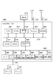
図1は、本発明に係る画像形成システム構成を説明するためのブロック図である。以下、構成および動作について説明する。
【0025】
本画像形成システムは、画像入力装置である白黒原稿読み取り可能な白黒スキャナ100、同画像入力装置であるカラー原稿読み取り可能なカラースキャナ200、画像出力装置である低速の白黒プリンタ(画像出力装置)300、中速の白黒プリンタ(画像出力装置)400、高速の両面印刷可能白黒プリンタ(画像出力装置)500、カラープリンタ(画像出力装置)600、オフラインでプリント用紙の後処理が可能なオフラインフィニッシャ700、大容量ストレージを有するサーバコンピュータ800、同個人ユーザ向けのパーソナルコンピュータ900、公知のネットワーク構築の伝送手段であるイーサネット1000、白黒スキャナ100と低速白黒プリンタ300を接続する白黒専用ビデオバス1100、同カラースキャナ200とカラープリンタ600を接続するカラー専用ビデオバス1200とで構成されている。
【0026】
画像入力装置100及び画像入力装置200には、画像読み取り制御と画像転送制御を行う画像制御装置(Image Controller)2000が図示しない専用バスにより接続されている。
【0027】
また、画像出力装置300,400,500,600には、部門IDを記憶する記憶手段(不揮発性の記憶媒体)を有し、あらかじめ所定のデバイスを介して該記憶手段に登録されているとする。
【0028】
また、プリント用紙の後処理がオンラインで可能なオンラインフィニッシャがそれぞれ接続されているが、本発明には直接関係しないので詳細な説明はしない。
【0029】
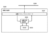
以下、図2を参照して、図1に示した画像制御装置(Controller Unit)2000の構成について説明する。
【0030】
図2は、本発明の一実施形態を示す画像制御装置の構成を説明するブロック図であり、図1に示し画像制御装置2000の詳細構成に対応する。
【0031】
図において、画像制御装置2000は、画像入力デバイスであるスキャナ(Scanner)100や画像出力デバイスであるプリンタ(Printer)300と接続し、一方ではLAN1000や公衆回線(WAN)2051と接続することで、画像情報やデバイス情報の入出力を行う為のコントローラである。
【0032】
2001はCPUで、システム全体を制御するコントローラとして機能する。2002はRAMで、CPU2001が動作するためのシステムワークメモリであり、画像データを一時記憶するための画像メモリとしても使用される。
【0033】
2003はROMで、ブートROMとして機能し、システムのブートプログラムが格納されている。2004はハードディスクドライブ(HDD)で、システムソフトウエア、画像データを格納する。2006は操作部I/Fで、操作部(UI)2012とのインタフェースとして機能し、操作部2012に表示する画像データを操作部2012に対して出力する。また、操作部2012から本システム使用者が入力した情報を、CPU2001に伝える役割をする。
【0034】
2010はネットワーク(Network)で、LAN1000に接続し、情報の入出力を行う。2050はモデム(MODEM)で、公衆回線2051に接続し、情報の入出力を行う。以上のデバイスがシステムバス2007上に配置される。
【0035】
2005はイメージバスインタフェース(Image BusI/F)で、システムバス2007と画像データを高速で転送する画像バス2008を接続し、データ構造を変換するバスブリッジである。2008は画像バスで、PCIバスなどの高速バスで構成される。なお、画像バス2008上には後述するデバイスが配置される。
【0036】
2060はラスターイメージプロセッサ(RIP)で、PDLコードをビットマップイメージに展開する。2020はデバイスI/F部で、画像入出力デバイスであるスキャナ100やプリンタ300と画像制御部2000を接続し、画像データの同期系/非同期系の変換を行う。
【0037】
2080はスキャナ画像処理部で、入力画像データに対し補正、加工、編集を行う。2090はプリンタ画像処理部で、プリント出力画像データに対して、プリンタの補正、解像度変換等を行う。2030は画像回転部で、画像データの回転を行う。2040は画像圧縮部で、多値画像データはJPEG、2値画像データはJBIG、MMR、MHの圧縮伸長処理を行う。
【0038】
また、HDD2004には、ネットワーク(LAN1000)に接続されているノードに関する画像出力速度、設置位置などの情報がアドレス毎に保存されている。
【0039】
以後、画像入力部100と画像制御装置2000と画像出力装置300を例にとり、第1システム機器の詳細を説明する。
【0040】
<白黒スキャナ+制御装置+白黒プリンタの例>
〈画像入力部(スキャナ)〉
図3は、図2に示した画像入力部100の構成をを説明する外観図である。
【0041】
図において、2070は画像入力デバイスであるスキャナ部で、原稿となる紙上の画像を照明し、CCDラインセンサ(図示せず)を走査することで、後述するラスターイメージデータ2071として電気信号に変換する。原稿用紙は原稿フィーダ2072のトレイ2073にセットし、装置使用者が操作部2012から読み取り起動指示することにより、CPU2001がスキャナ2070に指示を与え、フィーダ2072は原稿用紙を1枚ずつフィードし原稿画像の読み取り動作を行う。
【0042】
〈画像形成部(プリンタ)〉
図4は、図2に示した画像出力装置300の構成を説明する外観図である。
【0043】
図において、2095は画像出力デバイスであるプリンタ部で、ラスターイメージデータを用紙上の画像に変換する部分であり、その方式は感光体ドラムや感光体ベルトを用いた電子写真方式、微少ノズルアレイからインクを吐出して用紙上に直接画像を印字するインクジェット方式等があるが、どの方式でも構わない。プリント動作の起動は、図示しないコントローラからの指示によって開始する。
【0044】
また、プリンタ部2095には、異なる用紙サイズまたは異なる用紙向きを選択できるように複数の給紙段を持ち、それに対応した用紙カセット2101、2102、2103、2104がある。また、排紙トレイ2111は印字し終わった用紙を受けるものである。
【0045】
〈スキャナ画像処理部〉
図5は、図2に示したスキャナ画像処理部2080の構成を説明するブロック図である。
【0046】
図5において、2081は画像バスI/Fコントローラで、画像バス2008と接続し、そのバスアクセスシーケンスを制御する働きと、スキャナ画像処理部2080内の各デバイスの制御及びタイミングを発生させる。
【0047】
2082はフィルタ処理部で、空間フィルタでコンポリューション演算を行う。2083は編集部で、例えば入力画像データからマーカーペンで囲まれた開領域を認識して、その開領域内の画像データに対して、影つけ、網掛け、ネガポジ反転等の画像加工処理を行う。2084は変倍処理部で、読み取り画像の解像度を変える場合にラスターイメージの主走査方向について補間演算を行い拡大、縮小を行う。副走査方向の変倍については、画像読み取りラインセンサ(図示せず)を走査する速度を変えることで行う。
【0048】
2085はテーブルで、読み取った輝度データである画像データを濃度データに変換するために行うテーブル変換である。2086は2値化処理部で、多値のグレースケール画像データを、誤差拡散処理やスクリーン処理によって2値化する。
【0049】
なお、処理が終了した画像データは、再び画像バスI/Fコントローラ2081を介して、画像バス2008上に転送される。
【0050】
〈プリンタ画像処理部〉
図6は、図2に示したプリンタ画像処理部2090の詳細構成を説明するブロック図である。
【0051】
図6において、2091は画像バスI/Fコントローラで、画像バス2008と接続し、そのバスアクセスシーケンスを制御する働きと、スキャナ画像処理部2090内の各デバイスの制御及びタイミングを発生させる。2092は解像度変換部で、Network2011あるいは公衆回線2051から来た画像データを、プリンタ部2095の解像度に変換するための解像度変換を行う。2093はスムージング処理部で、解像度変換後の画像データのジャギー(斜め線等の白黒境界部に現れる画像のがさつき)を滑らかにする処理を行う。
【0052】
〈画像圧縮部〉
図7は、図2に示した画像圧縮部2040の詳細構成を説明するブロック図である。
【0053】
図7において、2041は画像バスI/Fコントローラで、画像バス2008と接続し、そのバスアクセスシーケンスを制御する働き、入力バッファ2042と出力バッファ2045とのデータのやりとりを行うためのタイミング制御及び、画像圧縮部2043に対するモード設定などの制御を行う。以下に画像圧縮処理部の処理手順を示す。2044はRAMである。
【0054】
画像バス2008を介して、CPU2001から画像バスI/Fコントローラ2041に画像圧縮制御のための設定を行う。この設定により画像バスI/Fコントローラ2041は画像圧縮部2043に対して画像圧縮に必要な設定(たとえばMMR圧縮・JBIG伸長等)を行う。必要な設定を行った後に、再度CPU2001から画像バスI/Fコントローラ2041に対して画像データ転送の許可を行う。
【0055】
この許可に従い、画像バスI/Fコントローラ2041はRAM2044もしくは画像バス2008上の各デバイスから画像データの転送を開始する。受け取った画像データは入力バッファ2042に一時格納され、画像圧縮部2043の画像データ要求に応じて一定のスピードで画像を転送する。
【0056】
この際、入力バッファ2042は画像バスI/Fコントローラ2041と、画像圧縮部2043の両者の間で、画像データを転送できるかどうかを判断し、画像バス2008からの画像データの読み込み、及び画像圧縮部2043への画像の書き込みが不可能である場合は、データの転送を行わないような制御を行う(以後このような制御をハンドシェークと呼称する)。画像圧縮部2043は受け取った画像データを、一旦RAM2044に格納する。
【0057】
これは画像圧縮を行う際には行う画像圧縮処理の種類によって、数ライン分のデータを要するためであり、最初の1ライン分の圧縮を行うためには数ライン分の画像データを用意してからでないと画像圧縮が行えないためである。
【0058】
画像圧縮を施された画像データは直ちに出力バッファ2045に送られる。出力バッファ2045では、画像バスI/Fコントローラ2041及び画像圧縮部2043とのハンドシェークを行い、画像データを画像バスI/Fコントローラ2041に転送する。画像バスI/Fコントローラ2041では転送された圧縮(もしくは伸長)された画像データをRAM2002もしくは画像バス2008上の各デバイスに転送する。
【0059】
こうした一連の処理は、CPU2001からの処理要求が無くなるまで(必要なページ数の処理が終わったとき)、もしくはこの画像圧縮部から停止要求が出るまで(圧縮及び伸長時のエラー発生時等)繰り返される。
【0060】
〈画像回転部〉
図8は、図2に示した画像回転部2030の詳細構成を説明するブロック図である。
【0061】
図8において、2031は画像バスI/Fコントローラで、画像バス2008と接続し、そのバスシーケンスを制御する働き、画像回転部2032にモード等を設定する制御、及び画像回転処理部2032に画像データを転送するためのタイミング制御を行う。以下に画像回転部2030の処理手順を図9,図10を参照しながら説明する。2033はRAMである。
【0062】
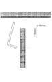
図9,図10は、図8に示した画像回転部2030の回転処理を説明する模式図である。
【0063】
画像バス2008を介して、CPU2001から画像バスI/Fコントローラ2031に画像回転制御のための設定を行う。この設定により画像バスI/Fコントローラ2031は画像回転部2032に対して画像回転に必要な設定(たとえば画像サイズや回転方向・角度等)を行う。必要な設定を行った後に、再度CPU2001から画像バスI/Fコントローラ2031に対して画像データ転送の許可を行う。
【0064】
この許可に従い、画像バスI/Fコントローラ2031はRAM2002もしくは画像バス2008上の各デバイスから画像データの転送を開始する。尚、ここでは32bitをそのサイズとし回転を行う画像サイズを32×32(bit)とし、又、画像バス2008上に画像データを転送させる際に32bitを単位とする画像転送を行うものとする(扱う画像は2値を想定する)。
【0065】
上述のように、32×32(bit)の画像を得るためには、上述の単位データ転送を32回行う必要があり、且つ不連続なアドレスから画像データを転送する必要がある(図9参照)。
【0066】
不連続アドレッシングにより転送された画像データは、読み出し時に所望の角度に回転されているように、RAM2033に書き込まれる。例えば、90度反時計方向回転であれば、最初に転送された32bitの画像データを、図10に示すようにY方向に書き込んでいく。読み出し時にX方向に読み出すことで、画像が回転される。32×32(bit)の画像回転(RAM2033への書き込み)が完了した後、画像回転部2032はRAM2033から上述した読み出し方法で画像データを読み出し、画像バスI/Fコントローラ2031に画像を転送する。
【0067】
回転処理された画像データを受け取った画像バスI/Fコントローラ2031は、連続アドレッシングを以って、RAM2002もしくは画像バス2008上の各デバイスにデータを転送する。
【0068】
こうした一連の処理は、CPU2001からの処理要求が無くなるまで(必要なページ数の処理が終わるまで)繰り返される。
【0069】
〈デバイスI/F部〉
図11は、図2に示したデバイスI/F部2020の詳細構成を説明するブロック図である。
【0070】
図11において、2021は画像バスI/Fコントローラで、画像バス2008と接続し、そのバスアクセスシーケンスを制御する働きと、デバイスI/F部2020内の各デバイスの制御及びタイミングを発生させる。
【0071】
また、外部のスキャナ部2070及びプリンタ部2095への制御信号を発生させる。スキャンバッファ2022は、スキャナ部2070から送られてくる画像データを一時保存し、画像バス2008に同期させて画像データを出力する。
【0072】
2023はシリアルパラレル・パラレルシリアル変換で、スキャンバッファ2022に保存された画像データを順番に並べて、あるいは分解して、画像バス2008に転送できる画像データのデータ幅に変換する。2024はパラレルシリアル・シリアルパラレル変換で、画像バス2008から転送された画像データを分解して、あるいは順番に並べて、プリントバッファ2025に保存できる画像データのデータ幅に変換する。
【0073】
2025はプリントバッファで、画像バス2008から送られてくる画像データを一時保存し、プリンタ部2095に同期させて画像データを出力する。画像スキャン時の処理手順を以下に示す。
【0074】
スキャナ部2070から送られてくる画像データをスキャナ部2070から送られてくるタイミング信号に同期させて、スキャンバッファ2022に保存する。そして、画像バス2008がPCIバスの場合には、バッファ内に画像データが32ビット以上入ったときに、画像データを先入れ先出しで32ビット分、バッファからシリアルパラレル・パラレルシリアル変換2023に送り、32ビットの画像データに変換し、画像バスI/Fコントローラ2021を通して画像バス2008上に転送する。画像プリント時の処理手順を以下に示す。
【0075】
画像バス2008がPCIバスの場合には、バッファ内の画像データを先入れ先出しで、バッファからシリアルパラレル・パラレルシリアル変換2023に送り、シリアル画像データに変換し、画像バスI/Fコントローラ2021を通して画像バス2008上に転送する。
【0076】
画像プリント時の処理手順を以下に示す。画像バス2008がPCIバスの場合には、画像バスから送られてくる32ビットの画像データを画像バスI/Fコントローラ2021で受け取り、パラレルシリアル・シリアルパラレル変換2024に送り、プリンタ部2095の入力データビット数の画像データに分解し、プリントバッファ2025に保存する。
【0077】
また、画像バス2008がIEEE1394の場合には、画像バスからおくられてくるシリアル画像データを画像バスI/Fコントローラ2021で受け取り、パラレルシリアル・シリアルパラレル変換2024に送り、プリンタ部2095の入力データビット数の画像データに変換し、プリントバッファ2025に保存する。そして、プリンタ部2095から送られてくるタイミング信号に同期させて、バッファ内の画像データを先入れ先出しで、プリンタ部2095に送る。
【0078】
次に、実施の形態について説明する。
【0079】
図1において、白黒プリンタ300、400、500は両面が可能なプリンタ、カラープリンタ600は両面が不可能なプリンタ、プリンタ300,500,600は部門ID001を有すると仮定する。
【0080】
<機能制限処理>
図12は、本発明に係る画像制御装置におけるデータ処理手順の一例を示すフローチャートであり、読み取った画像の画像出力装置(プリンタ)への機能制限処理を自動的に行う処理手順に対応する。なお、Step−1〜Step−17は各ステップを示す。
【0081】
また、本実施形態は、画像入力装置200で読みとった画像を画像出力装置300と画像出力装置400と画像出力装置500とに出力を行うべく操作部2012より指示がされた場合の機能制限あるいは装置制限する例である。また、操作部2012には、読み取りをスタートするスタートキー、どの画像出力装置に出力するかを選択する画面に移行する画像出力装置選択キー(図示しない)が存在する。なお、画像出力装置選択キーはLCD上のソフトキーとして存在し、表示したり、消去したりが可能になっている。
【0082】
図12のStep−1で、操作部2012において部門ID001が設定されると、Step−2で、ネットワークを介してプリンタ300、400、500、600部門IDを確認する。
【0083】
次いで、Step−3で、プリンタ300に部門ID001が登録されているかどうかを確認し、ID001が登録されていると判断した場合は、Step−4で、プリンタ300部門フラグをONする。そして、Step−5で、プリンタ400に部門ID001が登録されているかどうかを確認し、ID001が登録されていると判断した場合、Step−6で、プリンタ400部門フラグをONする。
【0084】
次いで、Step−7で、プリンタ500に部門ID001が登録されているかどうかを確認し、ID001が登録されていると判断した場合、Step−8でプリンタ500部門フラグをONする。
【0085】
次いで、Step−9で、プリンタ600に部門ID001が登録されているかどうかを確認し、ID001が登録されていると判断した場合、Step−10で、プリンタ600部門フラグをONする。
【0086】
次いで、Step−11で、前記部門フラグがONかどうかの判断を行い、YESならば、Step−12で、伝送媒体に接続されている装置として、すなわち画像出力装置300,500,600を操作部2012上に表示する。
【0087】
一方、Step−11で、NOの場合、部門IDが登録されていない装置の為、画像出力装置として画像出力装置300,500,600を選択不可とし、Step−13で、操作部2012上で網掛け非表示処理を行う。
【0088】
その後、Step−14で、操作者は表示されている装置のうちいくつかを選択し、機器は選択された画像出力装置を記憶しておく。なお、ここで、操作部2012より機能(両面機能設定)が選択される場合がある。
【0089】
その後、Step−15で、選択した装置(プリンタ600選択)の両面機能をサーチし、Step−16で、Step−15でサーチした結果選択された画像出力装置に両面機能がない場合には両面キーを消去し、Step−17で、処理を終了する。
【0090】
この状態でスタートキーが押されると、Step14で選択された画像出力装置に画像を送信し、それぞれの画像出力装置で出力されることとなる。
【0091】
また、本実施形態は両面機能にて説明したが、同様の方法で全ての機能(例えばレイアウト印刷機能(2in1等),ステイプル機能,排紙機能(フェースダウン排紙,フェースアップ排紙,指定ビン排紙,ソート排紙)にも容易に適用可能なことは明白である。なお、選択される用紙サイズを条件として機能制限,装置制限をかけるように構成してもよい。
【0092】
さらに、各画像出力装置に対する部門IDの登録処理には、サーバ装置800により各画像出力装置にコマンドを発行して、部門IDの登録と削除を行えるものとする。
【0093】
上記実施形態によれば、複数の画像出力装置の選択を考慮した、重連時の部門ID制御と機能制限処理を自動的に行うことで、ユーザの設定ミスによるミスプリントを防止し、ユーザが設定する際に、複数のプリンタの機能をかんがみることなく容易に機能を設定する効果がある。
【0094】
以下、図13に示すメモリマップを参照して本発明に係る画像制御装置を適用可能な画像形成システムで読み出し可能なデータ処理プログラムの構成について説明する。
【0095】
図13は、本発明に係る画像制御装置を適用可能な画像形成システムで読み出し可能な各種データ処理プログラムを格納する記憶媒体のメモリマップを説明する図である。
【0096】
なお、特に図示しないが、記憶媒体に記憶されるプログラム群を管理する情報、例えばバージョン情報,作成者等も記憶され、かつ、プログラム読み出し側のOS等に依存する情報、例えばプログラムを識別表示するアイコン等も記憶される場合もある。
【0097】
さらに、各種プログラムに従属するデータも上記ディレクトリに管理されている。また、各種プログラムをコンピュータにインストールするためのプログラムや、インストールするプログラムが圧縮されている場合に、解凍するプログラム等も記憶される場合もある。
【0098】
本実施形態における図12に示す機能が外部からインストールされるプログラムによって、ホストコンピュータにより遂行されていてもよい。そして、その場合、CD−ROMやフラッシュメモリやFD等の記憶媒体により、あるいはネットワークを介して外部の記憶媒体から、プログラムを含む情報群を出力装置に供給される場合でも本発明は適用されるものである。
【0099】
以上のように、前述した実施形態の機能を実現するソフトウエアのプログラムコードを記録した記憶媒体を、システムあるいは装置に供給し、そのシステムあるいは装置のコンピュータ(またはCPUやMPU)が記憶媒体に格納されたプログラムコードを読出し実行することによっても、本発明の目的が達成されることは言うまでもない。
【0100】
この場合、記憶媒体から読み出されたプログラムコード自体が本発明の新規な機能を実現することになり、そのプログラムコードを記憶した記憶媒体は本発明を構成することになる。
【0101】
プログラムコードを供給するための記憶媒体としては、例えば、フロッピーディスク,ハードディスク,光ディスク,光磁気ディスク,CD−ROM,CD−R,磁気テープ,不揮発性のメモリカード,ROM,EEPROM等を用いることができる。
【0102】
また、コンピュータが読み出したプログラムコードを実行することにより、前述した実施形態の機能が実現されるだけでなく、そのプログラムコードの指示に基づき、コンピュータ上で稼働しているOS(オペレーティングシステム)等が実際の処理の一部または全部を行い、その処理によって前述した実施形態の機能が実現される場合も含まれることは言うまでもない。
【0103】
さらに、記憶媒体から読み出されたプログラムコードが、コンピュータに挿入された機能拡張ボードやコンピュータに接続された機能拡張ユニットに備わるメモリに書き込まれた後、そのプログラムコードの指示に基づき、その機能拡張ボードや機能拡張ユニットに備わるCPU等が実際の処理の一部または全部を行い、その処理によって前述した実施形態の機能が実現される場合も含まれることは言うまでもない。
【0104】
【発明の効果】
以上説明したように、本発明によれば、設定された部門IDが各画像出力装置に登録済みかどうかを調査し、該調査結果に基づいて、選択可能な画像出力装置候補あるいは選択可能な機能を制限するので、複数の画像出力装置の選択を考慮した重連時の部門ID制御と機能制限処理を自動的に行え、ユーザの設定ミスによるミスプリントを防止し、ユーザが設定する際に、複数のプリンタの機能を鑑みることなく容易に機能を設定することができるという効果を奏する。
【図面の簡単な説明】
【図1】本発明に係る画像形成システム構成を説明するためのブロック図である。
【図2】本発明の一実施形態を示す画像制御装置の構成を説明するブロック図である。
【図3】図2に示した画像入力部の構成をを説明する外観図である。
【図4】図2に示した画像出力装置の構成をを説明する外観図である。
【図5】図2に示したスキャナ画像処理部の構成を説明するブロック図である。
【図6】図2に示したプリンタ画像処理部の詳細構成を説明するブロック図である。
【図7】図2に示した画像圧縮部の詳細構成を説明するブロック図である。
【図8】図2に示した画像回転部の詳細構成を説明するブロック図である。
【図9】図8に示した画像回転部の回転処理を説明する模式図である。
【図10】図8に示した画像回転部の回転処理を説明する模式図である。
【図11】図2に示したデバイスI/F部の詳細構成を説明するブロック図である。
【図12】本発明に係る画像制御装置におけるデータ処理手順の一例を示すフローチャートである。
【図13】本発明に係る画像制御装置を適用可能な画像形成システムで読み出し可能な各種データ処理プログラムを格納する記憶媒体のメモリマップを説明する図である。
【符号の説明】
100,200 画像入力装置
300,400,500,600,700 画像出力装置
800 サーバコンピュータ
2000 画像制御装置[0001]
BACKGROUND OF THE INVENTION
The present invention relates to an image control apparatus and an image control method for controlling an image forming system in which an image input apparatus and a plurality of image output apparatuses are connected via a predetermined communication medium, and a storage medium storing a computer-readable program It is about.
[0002]
[Prior art]
2. Description of the Related Art Conventionally, there has been proposed an image forming system in which an image input unit and a plurality of image output devices are connected via a transmission medium through an image control device. An image forming system in which an image output device (printer) is connected by a transmission medium is known.
[0003]
[Problems to be solved by the invention]
However, in recent years, due to the improvement of the network environment, there is a demand for department management by department ID even in a redundant system using a plurality of image output apparatuses (printers) including printers connected to a normal business network. In spite of this, there has been a problem that department-specific print processing cannot be sufficiently managed, such as misprinting due to a setting mistake of each user, because sufficient measures have not been taken.
[0004]
The present invention has been made to solve the above problems, and the object of the present invention is to investigate whether or not the set department ID has been registered in each image output device, and based on the investigation result, By restricting selectable image output device candidates or selectable functions, department ID control and function restriction processing can be performed automatically in consideration of selection of multiple image output devices. Image control apparatus and image control method capable of preventing misprinting and easily setting functions without considering the functions of a plurality of printers when set by a user, and a storage medium storing a computer-readable program Is to provide.
[0005]
[Means for Solving the Problems]
The present invention relates to a picture image control device which is connected via a plurality of image output apparatuses and a predetermined communication medium, receiving means for receiving a department ID entered by the user, it's on the receiving means and confirmation means received account ID whether or not it is registered, to confirm to each of the plurality of image output device via the predetermined communication medium, the sector ID of the plurality of image output devices Display means for displaying the image output device confirmed to be registered in a display format selectable by the user as the output destination of the image data input by the image input device, and the image output device Transmission means for transmitting the image data input by the image input device to an image output device selected by the user from among them .
[0023]
DETAILED DESCRIPTION OF THE INVENTION
Hereinafter, embodiments of the present invention will be described with reference to the drawings.
[0024]
FIG. 1 is a block diagram for explaining an image forming system configuration according to the present invention. The configuration and operation will be described below.
[0025]
The image forming system includes a
[0026]
An image control device (Image Controller) 2000 that performs image reading control and image transfer control is connected to the
[0027]
The
[0028]
Also, online finishers capable of online post-processing of print paper are connected to each other. However, since they are not directly related to the present invention, they will not be described in detail.
[0029]
The configuration of the image control apparatus (Controller Unit) 2000 shown in FIG. 1 will be described below with reference to FIG.
[0030]
FIG. 2 is a block diagram for explaining the configuration of the image control apparatus according to the embodiment of the present invention, and corresponds to the detailed configuration of the
[0031]
In the figure, an
[0032]
A
[0033]
[0034]
A
[0035]
[0036]
A raster image processor (RIP) 2060 expands the PDL code into a bitmap image. A device I /
[0037]
A scanner
[0038]
Also, the
[0039]
Hereinafter, the details of the first system device will be described by taking the
[0040]
<Example of monochrome scanner + control device + monochrome printer>
<Image input section (scanner)>
FIG. 3 is an external view for explaining the configuration of the
[0041]
In the figure,
[0042]
<Image forming unit (printer)>
FIG. 4 is an external view for explaining the configuration of the
[0043]
In the figure,
[0044]
The
[0045]
<Scanner image processing unit>
FIG. 5 is a block diagram illustrating the configuration of the scanner
[0046]
In FIG. 5,
[0047]
[0048]
[0049]
Note that the processed image data is transferred to the
[0050]
<Printer image processing section>
FIG. 6 is a block diagram illustrating a detailed configuration of the printer
[0051]
In FIG. 6, an image bus I /
[0052]
<Image compression section>
FIG. 7 is a block diagram illustrating a detailed configuration of the
[0053]
In FIG. 7, an image bus I /
[0054]
Settings for image compression control are performed from the
[0055]
In accordance with this permission, the image bus I /
[0056]
At this time, the
[0057]
This is because several lines of data are required depending on the type of image compression processing to be performed, and several lines of image data are prepared in order to compress the first one line. This is because the image cannot be compressed unless it is empty.
[0058]
The image data subjected to the image compression is immediately sent to the
[0059]
Such a series of processing is repeated until there is no processing request from the CPU 2001 (when processing of the required number of pages is completed) or until a stop request is issued from this image compression unit (when an error occurs during compression and expansion). It is.
[0060]
<Image rotation part>
FIG. 8 is a block diagram illustrating a detailed configuration of the
[0061]
In FIG. 8,
[0062]
9 and 10 are schematic diagrams for explaining the rotation processing of the
[0063]
Settings for image rotation control are performed from the
[0064]
In accordance with this permission, the image bus I /
[0065]
As described above, in order to obtain a 32 × 32 (bit) image, it is necessary to perform the above unit data transfer 32 times, and it is necessary to transfer image data from discontinuous addresses (see FIG. 9). ).
[0066]
The image data transferred by the discontinuous addressing is written in the
[0067]
The image bus I /
[0068]
Such a series of processing is repeated until there is no processing request from the CPU 2001 (until processing of the required number of pages is completed).
[0069]
<Device I / F part>
FIG. 11 is a block diagram illustrating a detailed configuration of the device I /
[0070]
In FIG. 11, an image bus I /
[0071]
Also, control signals to the
[0072]
[0073]
A print buffer 2025 temporarily stores the image data sent from the
[0074]
The image data sent from the
[0075]
When the
[0076]
The processing procedure at the time of image printing is shown below. When the
[0077]
When the
[0078]
Next, embodiments will be described.
[0079]
In FIG. 1, it is assumed that the
[0080]
<Function restriction processing>
FIG. 12 is a flowchart showing an example of a data processing procedure in the image control apparatus according to the present invention, and corresponds to a processing procedure for automatically performing a function restriction process on the image output apparatus (printer) of the read image. Step-1 to Step-17 indicate each step.
[0081]
Further, in the present embodiment, a function restriction or device when an instruction is given from the
[0082]
When the
[0083]
Next, in Step-3, it is confirmed whether or not the
[0084]
Next, in Step-7, it is confirmed whether or not the
[0085]
Next, in Step-9, it is confirmed whether or not the
[0086]
Next, in Step-11, it is determined whether or not the department flag is ON. If YES, in Step-12, as the device connected to the transmission medium, that is, the
[0087]
On the other hand, in the case of NO in Step-11, since the department ID is not registered, the
[0088]
Thereafter, in Step-14, the operator selects some of the displayed devices, and the device stores the selected image output device. Here, a function (double-sided function setting) may be selected from the
[0089]
Thereafter, in Step-15, the duplex function of the selected device (selecting the printer 600) is searched. In Step-16, if the selected image output device does not have the duplex function, the duplex key is searched. Is deleted, and the process ends at Step-17.
[0090]
When the start key is pressed in this state, an image is transmitted to the image output device selected in
[0091]
Although the present embodiment has been described with the double-side function, all functions (for example, layout printing function (2 in 1 etc.), stapling function, paper discharge function (face-down paper discharge, face-up paper discharge, designated bin) are performed in the same manner. It is obvious that the present invention can be easily applied to paper discharge, sort paper discharge, etc. It should be noted that the function restriction and the device restriction may be applied on the condition of the selected paper size.
[0092]
Further, in the department ID registration process for each image output apparatus, the
[0093]
According to the above-described embodiment, the department ID control and the function restriction process are performed automatically in consideration of selection of a plurality of image output devices, thereby preventing misprinting due to a user setting error and When setting, there is an effect of easily setting functions without considering the functions of a plurality of printers.
[0094]
The configuration of a data processing program that can be read by an image forming system to which the image control apparatus according to the present invention can be applied will be described below with reference to the memory map shown in FIG.
[0095]
FIG. 13 is a diagram illustrating a memory map of a storage medium that stores various data processing programs that can be read out by an image forming system to which the image control apparatus according to the present invention can be applied.
[0096]
Although not particularly illustrated, information for managing a program group stored in the storage medium, for example, version information, creator, etc. is also stored, and information depending on the OS on the program reading side, for example, a program is identified and displayed. Icons may also be stored.
[0097]
Further, data depending on various programs is also managed in the directory. In addition, a program for installing various programs in the computer, and a program for decompressing when the program to be installed is compressed may be stored.
[0098]
The functions shown in FIG. 12 in this embodiment may be performed by the host computer by a program installed from the outside. In this case, the present invention is applied even when an information group including a program is supplied to the output device from a storage medium such as a CD-ROM, a flash memory, or an FD, or from an external storage medium via a network. Is.
[0099]
As described above, a storage medium storing software program codes for realizing the functions of the above-described embodiments is supplied to the system or apparatus, and the computer (or CPU or MPU) of the system or apparatus stores the storage medium in the storage medium. It goes without saying that the object of the present invention can also be achieved by reading and executing the programmed program code.
[0100]
In this case, the program code itself read from the storage medium realizes the novel function of the present invention, and the storage medium storing the program code constitutes the present invention.
[0101]
As a storage medium for supplying the program code, for example, a floppy disk, a hard disk, an optical disk, a magneto-optical disk, a CD-ROM, a CD-R, a magnetic tape, a nonvolatile memory card, a ROM, an EEPROM, or the like is used. it can.
[0102]
Further, by executing the program code read by the computer, not only the functions of the above-described embodiments are realized, but also an OS (operating system) or the like running on the computer based on the instruction of the program code. It goes without saying that a case where the function of the above-described embodiment is realized by performing part or all of the actual processing and the processing is included.
[0103]
Further, after the program code read from the storage medium is written to a memory provided in a function expansion board inserted into the computer or a function expansion unit connected to the computer, the function expansion is performed based on the instruction of the program code. It goes without saying that the case where the CPU or the like provided in the board or the function expansion unit performs part or all of the actual processing and the functions of the above-described embodiments are realized by the processing.
[0104]
【The invention's effect】
As described above , according to the present invention , it is investigated whether the set department ID has been registered in each image output apparatus, and based on the investigation result, selectable image output apparatus candidates or selectable functions. Therefore, department ID control and function restriction processing can be performed automatically in consideration of selection of a plurality of image output devices, and misprinting due to user setting mistakes can be prevented. There is an effect that functions can be easily set without considering the functions of a plurality of printers.
[Brief description of the drawings]
FIG. 1 is a block diagram for explaining an image forming system configuration according to the present invention.
FIG. 2 is a block diagram illustrating a configuration of an image control apparatus according to an embodiment of the present invention.
3 is an external view illustrating a configuration of an image input unit illustrated in FIG. 2. FIG.
4 is an external view for explaining the configuration of the image output apparatus shown in FIG. 2;
5 is a block diagram illustrating a configuration of a scanner image processing unit illustrated in FIG.
6 is a block diagram illustrating a detailed configuration of a printer image processing unit illustrated in FIG. 2;
7 is a block diagram illustrating a detailed configuration of an image compression unit illustrated in FIG. 2. FIG.
8 is a block diagram illustrating a detailed configuration of an image rotation unit illustrated in FIG.
9 is a schematic diagram illustrating a rotation process of the image rotation unit illustrated in FIG.
10 is a schematic diagram illustrating a rotation process of the image rotation unit illustrated in FIG.
11 is a block diagram illustrating a detailed configuration of a device I / F unit illustrated in FIG. 2;
FIG. 12 is a flowchart showing an example of a data processing procedure in the image control apparatus according to the present invention.
FIG. 13 is a diagram illustrating a memory map of a storage medium that stores various data processing programs that can be read by an image forming system to which the image control apparatus according to the present invention can be applied.
[Explanation of symbols]
100, 200
Claims (17)
ユーザによって入力された部門IDを受信する受信手段と、
前記受信手段によって受信された部門IDが登録されているか否かを、前記所定の通信媒体を介して前記複数の画像出力装置それぞれに対して確認する確認手段と、
前記複数の画像出力装置のうち前記部門IDが登録されていることが確認された画像出力装置を、画像入力装置によって入力された画像データの出力先としてユーザが選択可能な表示形式で表示する表示手段と、
前記表示された画像出力装置の中からユーザに選択された画像出力装置に、前記画像入力装置によって入力された画像データを送信する送信手段と、
を有することを特徴とする画像制御装置。A connection has been images controller via a plurality of image output apparatuses and a predetermined communication medium,
Receiving means for receiving the department ID input by the user ;
And confirmation means for sector ID received me by the receiving means whether or not it is registered, to confirm for each said predetermined communication medium said plurality of image output devices through,
A display that displays an image output device in which the department ID is registered among the plurality of image output devices in a display format that can be selected by the user as an output destination of image data input by the image input device. Means,
Transmitting means for transmitting the image data input by the image input device to an image output device selected by the user from among the displayed image output devices;
An image control apparatus comprising:
前記表示手段は、前記モード設定手段により設定された画像形成モードに応じて、選択可能に表示する画像出力装置を制限することを特徴とする請求項1又は2に記載の画像制御装置。Having mode setting means for setting a desired image forming mode;
3. The image control apparatus according to claim 1, wherein the display unit restricts an image output device to be displayed in a selectable manner according to an image forming mode set by the mode setting unit.
前記表示手段は、前記機能設定手段により設定された機能に応じて、選択可能に表示する画像出力装置を制限することを特徴とする請求項1又は2に記載の画像制御装置。Having function setting means for setting a desired image processing function;
The display means, in accordance with the set function by the function setting means, the image control device according to claim 1 or 2, characterized in that to limit the image output device that selectively displayed.
ユーザによって入力された部門IDを受信する受信工程と、
前記受信工程によって受信された部門IDが登録されているか否かを、前記所定の通信媒体を介して前記複数の画像出力装置それぞれに対して確認する確認工程と、
前記複数の画像出力装置のうち前記部門IDが登録されていることが確認された画像出力装置を、画像入力装置によって入力された画像データの出力先としてユーザが選択可能な表示形式で表示する表示工程と、
前記表示された画像出力装置の中からユーザに選択された画像出力装置に、前記画像入力装置によって入力された画像データを送信する送信工程と、
を有することを特徴とする画像制御方法。An image control method in connection to the images controller via a plurality of image output apparatuses and a predetermined communication medium,
A receiving process for receiving the department ID input by the user ;
A confirmation step of sector ID received by said receiving step whether it is registered, to confirm for each said predetermined communication medium said plurality of image output devices through,
A display that displays an image output device in which the department ID is registered among the plurality of image output devices in a display format that can be selected by the user as an output destination of image data input by the image input device. Process,
A transmission step of transmitting the image data input by the image input device to an image output device selected by the user from among the displayed image output devices;
An image control method comprising:
ユーザによって入力された部門IDを受信する受信工程と、
前記受信工程によって受信された部門IDが登録されているか否かを、前記所定の通信媒体を介して前記複数の画像出力装置それぞれに対して確認する確認工程と、
前記複数の画像出力装置のうち前記部門IDが登録されていることが確認された画像出力装置を、画像入力装置によって入力された画像データの出力先としてユーザが選択可能な表示形式で表示する表示工程と、
前記表示された画像出力装置の中からユーザに選択された画像出力装置に、前記画像入力装置によって入力された画像データを送信する送信工程と、
を有することを特徴とするコンピュータが読み出し可能なプログラムを格納した記憶媒体。A storage medium from which a computer stores a readable program for controlling the images control apparatus as connected via a plurality of image output apparatuses and a predetermined communication medium,
A receiving process for receiving the department ID input by the user ;
A confirmation step of sector ID received me by the said receiving step whether it is registered, to confirm for each said predetermined communication medium said plurality of image output devices through,
A display that displays an image output device in which the department ID is registered among the plurality of image output devices in a display format that can be selected by the user as an output destination of image data input by the image input device. Process,
A transmission step of transmitting the image data input by the image input device to an image output device selected by the user from among the displayed image output devices;
A computer-readable storage medium storing a computer-readable program.
Priority Applications (1)
| Application Number | Priority Date | Filing Date | Title |
|---|---|---|---|
| JP22809799A JP4280366B2 (en) | 1999-08-12 | 1999-08-12 | Image control apparatus, image control method, and storage medium storing computer-readable program |
Applications Claiming Priority (1)
| Application Number | Priority Date | Filing Date | Title |
|---|---|---|---|
| JP22809799A JP4280366B2 (en) | 1999-08-12 | 1999-08-12 | Image control apparatus, image control method, and storage medium storing computer-readable program |
Publications (2)
| Publication Number | Publication Date |
|---|---|
| JP2001051819A JP2001051819A (en) | 2001-02-23 |
| JP4280366B2 true JP4280366B2 (en) | 2009-06-17 |
Family
ID=16871153
Family Applications (1)
| Application Number | Title | Priority Date | Filing Date |
|---|---|---|---|
| JP22809799A Expired - Fee Related JP4280366B2 (en) | 1999-08-12 | 1999-08-12 | Image control apparatus, image control method, and storage medium storing computer-readable program |
Country Status (1)
| Country | Link |
|---|---|
| JP (1) | JP4280366B2 (en) |
Families Citing this family (3)
| Publication number | Priority date | Publication date | Assignee | Title |
|---|---|---|---|---|
| JP4490192B2 (en) | 2004-07-02 | 2010-06-23 | 株式会社エヌ・ティ・ティ・ドコモ | Multitask execution system |
| JP4847271B2 (en) | 2006-10-13 | 2011-12-28 | キヤノン株式会社 | Image processing system, information processing apparatus, image processing method, and program |
| JP6187076B2 (en) * | 2013-09-18 | 2017-08-30 | ブラザー工業株式会社 | Program, information processing apparatus, and control method for information processing apparatus |
-
1999
- 1999-08-12 JP JP22809799A patent/JP4280366B2/en not_active Expired - Fee Related
Also Published As
| Publication number | Publication date |
|---|---|
| JP2001051819A (en) | 2001-02-23 |
Similar Documents
| Publication | Publication Date | Title |
|---|---|---|
| US7414748B2 (en) | Image input/output apparatus, method of controlling image input/output apparatus, image input/output system, and storage media | |
| JP2001156987A (en) | System and method for forming image and storage medium | |
| JP4280366B2 (en) | Image control apparatus, image control method, and storage medium storing computer-readable program | |
| JP4077958B2 (en) | Data processing apparatus, method, and storage medium storing program | |
| JP2001356853A (en) | Image processor and state display control method of the same | |
| JP4743916B2 (en) | Image processing apparatus and control method thereof | |
| JP4174506B2 (en) | Data processing apparatus, method, and storage medium storing program | |
| JP2000151873A (en) | Information processing system and information processing method | |
| JP2001159964A (en) | Image formation system, control method for image formation system and storage medium | |
| JP4521935B2 (en) | Image processing system, control method therefor, and storage medium | |
| JP3950530B2 (en) | Image processing apparatus and control method thereof | |
| JP2002144670A (en) | Imaging system, its post-processing method and storage medium | |
| JP3854787B2 (en) | Image processing apparatus and control method thereof | |
| JP2001337797A (en) | Communication unit, communication system, image input device, image input system, image formation device and image formation system | |
| JP3755867B2 (en) | Image forming apparatus and recording medium | |
| JP3870095B2 (en) | Image forming apparatus and control method thereof | |
| JP4109903B2 (en) | Printing apparatus and printing method | |
| JP4078041B2 (en) | Image input / output device, image input / output method, image input / output system, and storage medium | |
| JP2003167705A (en) | Image processing system, information processor, image processor, image output control method, storage medium, and program | |
| JP3990887B2 (en) | Information processing apparatus, job processing method, and storage medium | |
| JP2003018389A (en) | Image processor, network system, image processing method, medium for providing control program, and the control program | |
| JP2003337682A (en) | Image processing device and image processing system | |
| JP2001358892A (en) | Image forming system and control method therefor | |
| JP2003289412A (en) | Image processor | |
| JP2000132359A (en) | Image forming system, image controller, image forming method and storage medium |
Legal Events
| Date | Code | Title | Description |
|---|---|---|---|
| A621 | Written request for application examination |
Free format text: JAPANESE INTERMEDIATE CODE: A621 Effective date: 20060612 |
|
| RD03 | Notification of appointment of power of attorney |
Free format text: JAPANESE INTERMEDIATE CODE: A7423 Effective date: 20080107 |
|
| RD04 | Notification of resignation of power of attorney |
Free format text: JAPANESE INTERMEDIATE CODE: A7424 Effective date: 20080220 |
|
| A977 | Report on retrieval |
Free format text: JAPANESE INTERMEDIATE CODE: A971007 Effective date: 20081104 |
|
| A131 | Notification of reasons for refusal |
Free format text: JAPANESE INTERMEDIATE CODE: A131 Effective date: 20081202 |
|
| A521 | Written amendment |
Free format text: JAPANESE INTERMEDIATE CODE: A523 Effective date: 20090129 |
|
| TRDD | Decision of grant or rejection written | ||
| A01 | Written decision to grant a patent or to grant a registration (utility model) |
Free format text: JAPANESE INTERMEDIATE CODE: A01 Effective date: 20090303 |
|
| A01 | Written decision to grant a patent or to grant a registration (utility model) |
Free format text: JAPANESE INTERMEDIATE CODE: A01 |
|
| A61 | First payment of annual fees (during grant procedure) |
Free format text: JAPANESE INTERMEDIATE CODE: A61 Effective date: 20090316 |
|
| FPAY | Renewal fee payment (event date is renewal date of database) |
Free format text: PAYMENT UNTIL: 20120319 Year of fee payment: 3 |
|
| R150 | Certificate of patent or registration of utility model |
Ref document number: 4280366 Country of ref document: JP Free format text: JAPANESE INTERMEDIATE CODE: R150 Free format text: JAPANESE INTERMEDIATE CODE: R150 |
|
| FPAY | Renewal fee payment (event date is renewal date of database) |
Free format text: PAYMENT UNTIL: 20130319 Year of fee payment: 4 |
|
| FPAY | Renewal fee payment (event date is renewal date of database) |
Free format text: PAYMENT UNTIL: 20140319 Year of fee payment: 5 |
|
| LAPS | Cancellation because of no payment of annual fees |