JP4280065B2 - Dry pipe valve for fire prevention sprinkler system - Google Patents
Dry pipe valve for fire prevention sprinkler system Download PDFInfo
- Publication number
- JP4280065B2 JP4280065B2 JP2002510153A JP2002510153A JP4280065B2 JP 4280065 B2 JP4280065 B2 JP 4280065B2 JP 2002510153 A JP2002510153 A JP 2002510153A JP 2002510153 A JP2002510153 A JP 2002510153A JP 4280065 B2 JP4280065 B2 JP 4280065B2
- Authority
- JP
- Japan
- Prior art keywords
- clapper
- valve seat
- air
- water
- dry pipe
- Prior art date
- Legal status (The legal status is an assumption and is not a legal conclusion. Google has not performed a legal analysis and makes no representation as to the accuracy of the status listed.)
- Expired - Fee Related
Links
Images


Classifications
-
- F—MECHANICAL ENGINEERING; LIGHTING; HEATING; WEAPONS; BLASTING
- F16—ENGINEERING ELEMENTS AND UNITS; GENERAL MEASURES FOR PRODUCING AND MAINTAINING EFFECTIVE FUNCTIONING OF MACHINES OR INSTALLATIONS; THERMAL INSULATION IN GENERAL
- F16K—VALVES; TAPS; COCKS; ACTUATING-FLOATS; DEVICES FOR VENTING OR AERATING
- F16K15/00—Check valves
- F16K15/18—Check valves with actuating mechanism; Combined check valves and actuated valves
- F16K15/182—Check valves with actuating mechanism; Combined check valves and actuated valves with actuating mechanism
- F16K15/1821—Check valves with actuating mechanism; Combined check valves and actuated valves with actuating mechanism for check valves with a hinged or pivoted closure member
-
- F—MECHANICAL ENGINEERING; LIGHTING; HEATING; WEAPONS; BLASTING
- F16—ENGINEERING ELEMENTS AND UNITS; GENERAL MEASURES FOR PRODUCING AND MAINTAINING EFFECTIVE FUNCTIONING OF MACHINES OR INSTALLATIONS; THERMAL INSULATION IN GENERAL
- F16K—VALVES; TAPS; COCKS; ACTUATING-FLOATS; DEVICES FOR VENTING OR AERATING
- F16K15/00—Check valves
- F16K15/02—Check valves with guided rigid valve members
- F16K15/03—Check valves with guided rigid valve members with a hinged closure member or with a pivoted closure member
-
- A—HUMAN NECESSITIES
- A62—LIFE-SAVING; FIRE-FIGHTING
- A62C—FIRE-FIGHTING
- A62C35/00—Permanently-installed equipment
- A62C35/58—Pipe-line systems
- A62C35/62—Pipe-line systems dry, i.e. empty of extinguishing material when not in use
-
- A—HUMAN NECESSITIES
- A62—LIFE-SAVING; FIRE-FIGHTING
- A62C—FIRE-FIGHTING
- A62C35/00—Permanently-installed equipment
- A62C35/58—Pipe-line systems
- A62C35/68—Details, e.g. of pipes or valve systems
-
- F—MECHANICAL ENGINEERING; LIGHTING; HEATING; WEAPONS; BLASTING
- F16—ENGINEERING ELEMENTS AND UNITS; GENERAL MEASURES FOR PRODUCING AND MAINTAINING EFFECTIVE FUNCTIONING OF MACHINES OR INSTALLATIONS; THERMAL INSULATION IN GENERAL
- F16K—VALVES; TAPS; COCKS; ACTUATING-FLOATS; DEVICES FOR VENTING OR AERATING
- F16K17/00—Safety valves; Equalising valves, e.g. pressure relief valves
- F16K17/36—Safety valves; Equalising valves, e.g. pressure relief valves actuated in consequence of extraneous circumstances, e.g. shock, change of position
- F16K17/38—Safety valves; Equalising valves, e.g. pressure relief valves actuated in consequence of extraneous circumstances, e.g. shock, change of position of excessive temperature
- F16K17/386—Safety valves; Equalising valves, e.g. pressure relief valves actuated in consequence of extraneous circumstances, e.g. shock, change of position of excessive temperature the closure members being rotatable or pivoting
-
- Y—GENERAL TAGGING OF NEW TECHNOLOGICAL DEVELOPMENTS; GENERAL TAGGING OF CROSS-SECTIONAL TECHNOLOGIES SPANNING OVER SEVERAL SECTIONS OF THE IPC; TECHNICAL SUBJECTS COVERED BY FORMER USPC CROSS-REFERENCE ART COLLECTIONS [XRACs] AND DIGESTS
- Y10—TECHNICAL SUBJECTS COVERED BY FORMER USPC
- Y10T—TECHNICAL SUBJECTS COVERED BY FORMER US CLASSIFICATION
- Y10T137/00—Fluid handling
- Y10T137/0318—Processes
- Y10T137/0324—With control of flow by a condition or characteristic of a fluid
- Y10T137/0379—By fluid pressure
-
- Y—GENERAL TAGGING OF NEW TECHNOLOGICAL DEVELOPMENTS; GENERAL TAGGING OF CROSS-SECTIONAL TECHNOLOGIES SPANNING OVER SEVERAL SECTIONS OF THE IPC; TECHNICAL SUBJECTS COVERED BY FORMER USPC CROSS-REFERENCE ART COLLECTIONS [XRACs] AND DIGESTS
- Y10—TECHNICAL SUBJECTS COVERED BY FORMER USPC
- Y10T—TECHNICAL SUBJECTS COVERED BY FORMER US CLASSIFICATION
- Y10T137/00—Fluid handling
- Y10T137/0318—Processes
- Y10T137/0402—Cleaning, repairing, or assembling
- Y10T137/0491—Valve or valve element assembling, disassembling, or replacing
-
- Y—GENERAL TAGGING OF NEW TECHNOLOGICAL DEVELOPMENTS; GENERAL TAGGING OF CROSS-SECTIONAL TECHNOLOGIES SPANNING OVER SEVERAL SECTIONS OF THE IPC; TECHNICAL SUBJECTS COVERED BY FORMER USPC CROSS-REFERENCE ART COLLECTIONS [XRACs] AND DIGESTS
- Y10—TECHNICAL SUBJECTS COVERED BY FORMER USPC
- Y10T—TECHNICAL SUBJECTS COVERED BY FORMER US CLASSIFICATION
- Y10T137/00—Fluid handling
- Y10T137/7722—Line condition change responsive valves
- Y10T137/7837—Direct response valves [i.e., check valve type]
- Y10T137/7866—Plural seating
-
- Y—GENERAL TAGGING OF NEW TECHNOLOGICAL DEVELOPMENTS; GENERAL TAGGING OF CROSS-SECTIONAL TECHNOLOGIES SPANNING OVER SEVERAL SECTIONS OF THE IPC; TECHNICAL SUBJECTS COVERED BY FORMER USPC CROSS-REFERENCE ART COLLECTIONS [XRACs] AND DIGESTS
- Y10—TECHNICAL SUBJECTS COVERED BY FORMER USPC
- Y10T—TECHNICAL SUBJECTS COVERED BY FORMER US CLASSIFICATION
- Y10T137/00—Fluid handling
- Y10T137/7722—Line condition change responsive valves
- Y10T137/7837—Direct response valves [i.e., check valve type]
- Y10T137/7876—With external means for opposing bias
- Y10T137/7877—With means for retaining external means in bias opposing position
-
- Y—GENERAL TAGGING OF NEW TECHNOLOGICAL DEVELOPMENTS; GENERAL TAGGING OF CROSS-SECTIONAL TECHNOLOGIES SPANNING OVER SEVERAL SECTIONS OF THE IPC; TECHNICAL SUBJECTS COVERED BY FORMER USPC CROSS-REFERENCE ART COLLECTIONS [XRACs] AND DIGESTS
- Y10—TECHNICAL SUBJECTS COVERED BY FORMER USPC
- Y10T—TECHNICAL SUBJECTS COVERED BY FORMER US CLASSIFICATION
- Y10T137/00—Fluid handling
- Y10T137/7722—Line condition change responsive valves
- Y10T137/7837—Direct response valves [i.e., check valve type]
- Y10T137/7898—Pivoted valves
- Y10T137/7903—Weight biased
-
- Y—GENERAL TAGGING OF NEW TECHNOLOGICAL DEVELOPMENTS; GENERAL TAGGING OF CROSS-SECTIONAL TECHNOLOGIES SPANNING OVER SEVERAL SECTIONS OF THE IPC; TECHNICAL SUBJECTS COVERED BY FORMER USPC CROSS-REFERENCE ART COLLECTIONS [XRACs] AND DIGESTS
- Y10—TECHNICAL SUBJECTS COVERED BY FORMER USPC
- Y10T—TECHNICAL SUBJECTS COVERED BY FORMER US CLASSIFICATION
- Y10T137/00—Fluid handling
- Y10T137/8158—With indicator, register, recorder, alarm or inspection means
- Y10T137/8359—Inspection means
Abstract
Description
【0001】
【発明の属する技術分野】
本発明は、ドライパイプ自動防火スプリンクラーシステムに関する。
【0002】
【発明の背景】
ドライパイプ自動防火スプリンクラーシステムは一般に、凍結温度にさらされる非加熱占有建物および構造物に自動スプリンクラー保護を提供するために使用される。ドライパイプスプリンクラーシステムは、確実な水の供給を提供する公共または民間の水道本管に接続され、一般に、指示型の水流弁たとえば水ゴングまたは他のアラーム流れ弁と、消防部間連絡と、ドライパイプ弁とを含む。ドライパイプシステムは主に、水が充満したパイプを使用することができない非加熱倉庫等で使用され、そのため、ドライパイプ弁は、これを構造物の加熱部分、たとえば、倉庫事務所内またはドライパイプ弁を凍結から保護する目的のために設けられた加熱エンクロージャ内に設置されることによって、凍結から保護されなければならない。
【0003】
ドライパイプスプリンクラーシステムのスプリンクラー部分は、湿式パイプスプリンクラーシステムに類似した配管の配列を有する。しかし、水ではなく、ドライパイプスプリンクラーシステムは、ドライパイプ弁上に圧力下で空気または窒素を含む。空気圧は、たとえば火災存在時に、1つまたはそれ以上のスプリンクラーが開くまで弁を閉鎖位置に保持することによって、ドライパイプ弁で供給本管内に水を抑制する。空気圧が失われることによってドライパイプ弁が開くことができ、水が弁を通って配管の配列内へ、火災の場所で開いたスプリンクラーへ流れることを可能にする。
【0004】
多くのドライパイプ弁が、差動型の単一クラッパ構造物である。これらの中心差動圧力弁は、クラッパヒンジピンの中心から等距離でその軸で同心的に位置するドライシステム座および水供給座を備えて設計される。下記の方程式から見られるように、差動比率は、空気座区域を水座区域で割った関係である。
【0005】
DF=(AD/WD)2*L1/L2
AD=√(DF*WD2)
ただし、
AD=システム(空気)弁座平均直径
WD=供給(水)座平均直径
DF=差動、すなわち、システム水圧とシステム空気圧との間の比率(5.5から6.0が業界基準である)
L1=ヒンジまたは旋回軸と空気圧の中心(すなわち、空気弁座軸)との間の距離
L2=ヒンジまたは旋回軸と水圧の中心(すなわち、水弁座軸)との間の距離である。
【0006】
例として、6インチ単一クラッパ差動型ドライパイプ弁用には、
WD=6;DF=5.5;L1=L2
AD=√DF*WD2=14インチ
である。
【0007】
典型的な比率の5.5(業界基準)である場合、6インチ直径の水供給は、したがって14インチ直径の空気弁座を必要とする。この弁設計は、非常に信頼性があり、比較的少ない数の部品から作られる。しかし、この関係も結果として、比較的大型の重い弁になり、したがって、設置するのが困難である。比較的軽い重量を達成するための代替設計は、機械的ラッチドライ弁である。この種類のドライパイプ弁は、比較的サイズが小さいが、より多くの構成要素を必要とし、比較的多数の部品が補助チャンバ内に位置するため、維持するのがより困難であることが多い。
【0008】
【課題を解決するための手段】
本発明の1つの態様によると、防火スプリンクラーシステム用の差動型ドライパイプ弁は、用水封止区域に対する有効空気封止区域の比率が、防火スプリンクラーシステムが作動されるシステム空気圧に対する用水圧の比率よりも小さい。
【0009】
本発明の別の態様によると、防火スプリンクラーシステム用のドライパイプ弁は、水弁座および空気弁座を有し、水弁座は上記空気弁座に対して中心がずれている。
【0010】
本発明のさらに別の態様によると、防火スプリンクラーシステム用の差動型ドライパイプ弁は、入口および出口と、入口に連通する水側チャンバおよび出口に連通する空気側チャンバと、その間に、空気弁軸を有する空気弁座および水弁軸を有する水弁座とを画成する弁本体を含む。クラッパが装着され、水が水弁座を通って流れるのに抵抗するための第1のクラッパ閉鎖位置と、水が水弁座を通って空気側チャンバへ向けて流れるのを可能にするための第2のクラッパ開放位置との間を、空気弁座に近接した旋回軸を中心にして旋回する。第1のクラッパ閉鎖位置にあるクラッパで空気弁座に封止係合するために空気弁シールが装着され、第1のクラッパ閉鎖位置にあるクラッパで水弁座に封止係合するために水弁シールが装着される。1つの実施形態において、空気弁座は旋回軸から第1の半径方向距離に中心を置かれ、水弁座は旋回軸から第2の半径方向距離だけ間隔をおかれ、第1の半径方向距離は第2の半径方向距離よりも大きい。別の実施形態において、空気弁座および水弁座は、非対称的に配列される。
【0011】
本発明のこの態様の好適な実施形態は、1つまたはそれ以上の下記の追加的な特徴を含んでもよい。クラッパは、空気側チャンバおよび防火スプリンクラーシステム内に維持された空気圧によって第1のクラッパ閉鎖位置に保持され、クラッパは、空気側チャンバおよび防火スプリンクラーシステム内の空気圧の減少時に、水側チャンバからの水圧によって第1のクラッパ閉鎖位置から第2のクラッパ開放位置へ向けて付勢される。好ましくは、空気側チャンバおよび防火スプリンクラーシステム内の空気圧の減少は、防火スプリンクラーシステムの1つまたはそれ以上の防火スプリンクラーを開くことから生じる。空気弁シールおよび/または水弁シールは、クラッパに装着される。ドライパイプ弁は、第1のラッチ部材位置で、クラッパが第1のクラッパ閉鎖位置から第2のクラッパ開放位置へ向けて動くのを可能にし且つ第2のクラッパ開放位置から第1のクラッパ閉鎖位置へ向けて戻る動きには抵抗するように適合されたラッチ部材をさらに含む。好ましくは、クラッパが第1のクラッパ閉鎖位置へ向けて戻る動きに抵抗する第1のラッチ部材位置と、クラッパが第2のクラッパ開放位置から第1のクラッパ閉鎖位置へ向けて戻る動きを可能にする第2のラッチ部材位置との間を動くために、ラッチ部材が本体に装着される。より好ましくは、ラッチ部材は、クラッパが第1のクラッパ閉鎖位置へ向けて戻る動きに抵抗する第1のラッチ部材位置から、クラッパが第1のクラッパ閉鎖位置へ向けて戻る動きを可能にする第2のラッチ部材位置へ向けて、ラッチ部材を動かすために、本体の外部に配置されたアクチュエータを含む。空気弁シールは、空気弁座に封止係合するために配置された第1の表面と、空気弁座上の空気弁シールへ封止圧力を加えるために露出された対向する第2の表面とを有する。水弁シールは、水弁座に封止係合するために配置された第1の表面と、水弁座上の水弁シールへ封止圧力を加えるために露出された対向する第2の表面とを有する。ドライパイプ弁は、単一のクラッパを含む。クラッパは、その第1のクラッパ閉鎖位置で、ほぼ空気弁座と水弁座との間に大気領域を画成する。好ましくは、ほぼ空気弁座と水弁座との間にクラッパによって画成された大気領域は、空気弁軸に対して非対称である。旋回軸から空気弁座中心への第1の半径方向距離は、旋回軸から水弁座中心への第2の半径方向距離の約1.8倍未満である。
【0012】
本発明の目的は、先行技術の類似構成のドライパイプ弁に比較して、可動部品数が少なく小型サイズでより軽量な簡略な構造のドライパイプ弁を提供することを含む。
【0013】
本発明の1つまたはそれ以上の実施形態の詳細は、添付の図面および下記で詳細に述べられている。本発明の他の特徴、目的および利点は、説明および図面から、および特許請求の範囲から明らかである。
様々な図面の同一の参照符号は、同一の要素を示す。
【0014】
【発明の実施の形態】
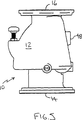
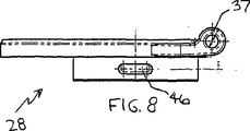
図1から5を参照すると、自動防火スプリンクラーシステムに使用するための、本発明の差動型ドライパイプ弁10は、入口14および出口16を画成する本体12と、カバー20によって画成される弁アクセスポート18(図4)とを有する。本体12は、入口14に連通する水側チャンバ22と、出口16に連通する空気側チャンバ24とをさらに画成する。また、図6から9を参照すると、空気弁座30および水弁座32によって囲まれた通路27を画成する座本体28が、水側チャンバ22と空気側チャンバ24との間の本体12によって画成された開口部26に配置される。さらに図10から14を参照すると、単一のクラッパ34が座本体28の耳36、37の間に装着されて、軸C(図2)を中心にして旋回し、これは、空気弁座30に近接して接する。最後に、図15から19および図20から23を参照すると、クラッパダイヤフラム保持プレート39によってクラッパ34に装着されたクラッパダイヤフラム38が、空気弁シール40および水弁シール42を画成する。クラッパ34の閉鎖位置で、空気弁シール40の表面41は、空気弁座30に封止的に係合し、水弁シール42の表面43は、水弁座32に封止的に係合し、両方とも水密式であり、水が水側チャンバ22から漏れて空気側チャンバ24へ向かうのに抵抗する。一般に空気弁座30およびシール40と、水弁座32およびシール42との間に座本体28およびクラッパダイヤフラム保持プレート39によって協働して画成された領域44は、周囲圧力で維持され、水弁座32およびシール42を通り過ぎて漏れた水が排水ポート46を通って放出される。
【0015】
次に特に図7および16を参照すると、本発明の差動型ドライパイプ弁10において、供給(水)圧力の軸W(すなわち、水弁座32および水弁シール42の軸)が、システム(空気)圧力の中心軸A(すなわち、空気弁座30および空気弁シール40の軸)に比較して、クラッパの旋回軸Cに相対的に近くに位置決めされる。空気弁座30からの旋回Cの後退(すなわち、空気弁座30からの旋回による後退量)も減少される。この配列は、ドライシステム座30および水供給座32の非同心位置のため、システム(空気)圧力に対して機械的利点を提供し、座本体28およびクラッパアセンブリ56のヒンジ接続から結果として得られる力が、クラッパ34およびクラッパダイヤフラム38を座に対して封止係合で保持するのを補助する。この構造(配列)の結果として、空気弁座30から中心がずれた水弁座32を備える本発明のドライパイプ弁10が作動する(すなわち、開放する)システム空気圧に対するシステム水圧の差を、対応する仕様の先行技術の差動型ドライパイプ弁と比較すると、著しく小型のクラッパおよび弁を有するドライパイプ弁で、業界基準の5.5(+/−0.3)内に維持することができ、たとえば、50%までの重量減少が、本発明のドライパイプ弁10で達成される。
【0016】
下記の式で見られるように、6インチ直径の弁用には、空気弁座30の直径は、先行技術の同心座設計にしたがった14インチに比較して、10.6インチへ減少される:
DF=(AD/WD)2*L1/L2
AD=√(DF*WD2*L2/L1)
WD=6;DF=5.5;L2=3;L1=AD/2
AD=√{DF*WD2*3/(AD/2)}
AD=3√(5.5*62*6)
AD=10.6インチ
結果は、用水封止領域に対する有効空気封止領域の比率が、防火スプリンクラーシステムが作動されるシステム空気圧に対する用水圧の比率よりも小さい、有利な構造の防火スプリンクラーシステム用差動型ドライパイプ弁である。
【0017】
再度図2を参照すると、クラッパ34が閉鎖位置から開放位置へ動くにつれて、たとえば、火災状態に応じて1つまたはそれ以上のスプリンクラーヘッドが開くため、空気側チャンバ24内の空気圧の減少時にラッチアセンブリ52が連結した旋回アーム50は、クラッパ34によって上方へ反り、クラッパが通過するのを可能にする。その後、旋回アーム50は、当初位置へ回転して戻り(たとえば重力下で)、クラッパアセンブリ56の下側に係合し(すなわち、クラッパ34および保持プレート39に係合し、ダイヤフラム38はその間に固定される)、たとえば図2に示されるように、防火スプリンクラー配管のシステム内へ水が流れるように、弁を開いたままに保持する。火災状態がおさまると、ドライパイプ弁10への水の流れが停止される。次いで、クラッパ34を含むクラッパアセンブリ56は、本体12の外部に位置するクラッパラッチアセンブリ52のアクチュエータ53へ下方圧力を加え、ばね54の力(矢印S)に打ち勝ち旋回アーム50を回転させ(矢印P)、クラッパアセンブリ56の外側端をクリアさせ、閉鎖位置へ向けて戻るのを可能にすることによって、座本体28の座30、32と共に封止係合して配置されるクラッパダイヤフラム38のシール40、42と共に、その閉鎖位置へ戻ることができる。その後、ばね54は、クラッパラッチアセンブリ52を待機位置へ戻し、旋回アーム50は、重力によって待機位置へ戻る。
【0018】
次に特に図18および19を参照すると、クラッパダイヤフラム38によって画成された空気弁シール40および水弁シール42が、それぞれ、セルフシールの自己整合式の可撓性のあるカンチレバーリップ60、62を備えて静止して構成される。シールリップは、それぞれ、対応する座30、32に係合することによって撓んだ第1の表面41、43と、封止補助圧力を加えるために露出された対向する第2の表面61、63を有する。水弁シール42の場合、水側チャンバ22の水によって圧力が表面63に加えられ、空気シール40の場合、空気側チャンバ24の空気によってまたは水によって圧力が表面61に加えられ、封止を容易にする。クラッパダイヤフラム38は一般に、ソフトラバーまたは約60から70のジュロメータを有するポリマー材料、たとえばEPDMから形成される。この比較的柔軟な封止材料が使用される場合には、クラッパ34には一般に、圧力下での押出または漏れに対して空気弁シール40を支持するために、外側リップ表面70(図14)が設けられる。表面70は、滑らかに湾曲しても階段状であってもよく、または、クラッパダイヤフラムが比較的硬い材料から形成される場合には、不必要であることがわかった。
【0019】
次に図24を参照すると、本発明の差動型ドライパイプ弁10が装備された典型的なドライパイプ防火スプリンクラーシステム100が記述される。ドライパイプ防火スプリンクラーシステム100は一般に、凍結以下の温度を受けやすい地理的領域に位置し、火災に対して保護されなければならない非加熱区域104を有する倉庫または他の構造物102を保護するために使用される。システム100は、消火用水道108、垂直パイプ110および逆止弁112を通って確実な外部水源、たとえば都市水道106に接続される。ドライパイプ弁10は、凍結に対して保護するために、熱が提供されるエンクロージャ113内、または、加熱される事務所区域114内に位置することが好ましい。ドライパイプ弁出口16は、配管116のシステムに接続され、間隔をおいたスプリンクラーヘッド118、119が構造物102中を延在する。
【0020】
凍結に対して保護するために、構造物の少なくとも非加熱部分内の配管のシステムの部分が、十分な圧力下で空気または他の気体、たとえば窒素で満たされ、上述のように、水供給圧力に対して閉鎖位置でドライパイプ弁10を維持する。火災状態の存在するところでは、1つまたはそれ以上のスプリンクラー118、119が、局所的な火災温度に応答して自動的に開けられる。結果として配管のシステム内(およびドライパイプ弁の空気側チャンバ内)の空気圧が減少するため、ドライパイプ弁が開くことができ、配管のシステムを通って開いたスプリンクラー(単/複)118、119へ水が流れることが可能になる。構造物の外側壁に装着された水モータゴング122が、スプリンクラーへの水の流れの外部警告を提供する。
【0021】
ひとたび火災が消火されると、防火システム100内へ水が流れることが、たとえば支柱指示弁120で中止される。次いでドライパイプ弁10のクラッパアセンブリ56は、ラッチアセンブリ52のアクチュエータを押し下げて旋回アーム50を回転させクラッパアセンブリを放すことによって、閉鎖位置へ戻ることができる。開いたスプリンクラーが交換された後に、配管116のシステムが再充電(すなわち圧縮空気で満た)され、ドライパイプ弁10の入口14への水の流れが復旧される。
【0022】
本発明の多くの実施形態が説明された。それにもかかわらず、本発明の精神および範囲から逸脱することなく、様々な修正例を作ることができることが理解される。たとえば、図1および2を参照すると、本体12は水入口ポート48を画成し、これによって、所定の量の水が空気側チャンバ24へ送出されて、クラッパ34を覆うことができる。この呼び水は、過去において、空気弁シール40の封止および潤滑を容易にするために有利であることがわかったが、たとえば封止材料の形成の改良のため、すべての事例に必要なわけではない。
【0023】
したがって、他の実施形態は、特許請求の範囲の範囲内である。
【図面の簡単な説明】
【図1】本発明のドライパイプ弁の斜視図である。
【図2】図3の2−2線に沿った図1のドライパイプ弁の第1の側断面図である。
【図3】図1のドライパイプ弁の平面図である。
【図4】図1のドライパイプ弁の側面図である。
【図5】図1のドライパイプ弁の、図4に対向する側の側面図である。
【図6】図1のドライパイプ弁の座本体の斜視図である。
【図7】図6の座本体の平面図である。
【図8】図6の座本体の第1側面図である。
【図9】図7の9−9線に沿った座本体の対向する第2側断面図である。
【図10】図1のドライパイプ弁のクラッパの斜視図である。
【図11】図10のクラッパの平面図である。
【図12】図10のクラッパの底面図である。
【図13】図10のクラッパの側面図である。
【図14】図11の14−14線に沿ったクラッパの側断面図である。
【図15】図1のドライパイプ弁のクラッパダイヤフラムの斜視図である。
【図16】図15のクラッパダイヤフラムの底面図である。
【図17】図16の17−17線に沿った図15のクラッパダイヤフラムの側断面図である。
【図18】図17の18−18線に沿った図15のクラッパダイヤフラムの空気弁シールおよび水弁シールの拡大側断面図である。
【図19】図17の19−19線に沿った図15のクラッパダイヤフラムの水弁シールの類似した拡大側断面図である。
【図20】図1のドライパイプ弁用のクラッパダイヤフラム保持プレートの斜視図である。
【図21】図20のクラッパダイヤフラム保持プレートの底面図である。
【図22】図21の22−22線に沿った図20のクラッパダイヤフラム保持プレートの側断面図である。
【図23】図22の23−23線に沿った図20のクラッパダイヤフラム保持プートのクラッパダイヤフラムサポートリムの拡大側断面図である。
【図24】本発明のドライパイプ弁を装備した自動防火スプリンクラーシステムの概略図である。
【符号の説明】
10 ドライパイプ弁
12 本体
14 入口
16 出口
18 弁アクセスポート
20 カバー
22 水側チャンバ
24 空気側チャンバ
26 開口部
27 通路
28 座本体
30 空気弁座
32 水弁座
34 クラッパ
36 耳
37 耳
38 クラッパダイヤフラム
39 クラッパダイヤフラム保持プレート
40 空気弁シール
41 表面
42 水弁シール
43 表面
44 領域
46 排水ポート
48 水入口ポート
50 旋回アーム
52 クラッパラッチアセンブリ
53 アクチュエータ
54 ばね
56 クラッパアセンブリ
60 カンチレバーリップ
61 第2の表面
62 カンチレバーリップ
63 第2の表面
70 外側リップ表面
100 ドライパイプ防火スプリンクラーシステム
102 倉庫または他の構造物
104 非加熱区域
106 都市水道
108 消火用水道
110 垂直パイプ
112 逆止弁
113 エンクロージャ
114 事務所区域
116 配管
118 スプリンクラーヘッド
119 スプリンクラーヘッド
120 支柱指示弁
122 水モータゴング[0001]
BACKGROUND OF THE INVENTION
The present invention relates to a dry pipe automatic fire prevention sprinkler system.
[0002]
BACKGROUND OF THE INVENTION
Dry pipe automatic fire protection sprinkler systems are commonly used to provide automatic sprinkler protection for unheated occupied buildings and structures that are exposed to freezing temperatures. Dry pipe sprinkler systems are connected to public or private water mains that provide a reliable supply of water, and are generally directed water flow valves such as water gongs or other alarm flow valves, fire department communications, Including pipe valves. Dry pipe systems are mainly used in non-heated warehouses where pipes filled with water cannot be used, so dry pipe valves are used for heating parts of structures, for example in warehouse offices or dry pipe valves. Must be protected from freezing by being placed in a heating enclosure provided for the purpose of protecting them from freezing.
[0003]
The sprinkler portion of the dry pipe sprinkler system has a piping arrangement similar to a wet pipe sprinkler system. However, instead of water, dry pipe sprinkler systems contain air or nitrogen under pressure on the dry pipe valve. Air pressure constrains water in the supply main with a dry pipe valve, for example in the presence of a fire, by holding the valve in a closed position until one or more sprinklers are opened. The loss of air pressure allows the dry pipe valve to open, allowing water to flow through the valve into the piping arrangement and to the open sprinkler at the fire location.
[0004]
Many dry pipe valves are differential single clapper structures. These central differential pressure valves are designed with a dry system seat and a water supply seat that are equidistant from the center of the clapper hinge pin and located concentrically on its axis. As can be seen from the equation below, the differential ratio is the relationship of the air space area divided by the water space area.
[0005]
DF = (AD / WD) 2 * L1 / L2
AD = √ (DF * WD 2 )
However,
AD = system (air) valve seat average diameter WD = supply (water) seat average diameter DF = differential, ie the ratio between system water pressure and system air pressure (5.5 to 6.0 is the industry standard)
L1 = distance between hinge or pivot axis and center of air pressure (ie, air valve seat axis) L2 = distance between hinge or pivot axis and center of water pressure (ie, water valve seat axis).
[0006]
As an example, for a 6 inch single clapper differential dry pipe valve,
WD = 6; DF = 5.5; L1 = L2
AD = √DF * WD 2 = 14 inches.
[0007]
With a typical ratio of 5.5 (industry standard), a 6 inch diameter water supply therefore requires a 14 inch diameter air valve seat. This valve design is very reliable and is made from a relatively small number of parts. However, this relationship also results in a relatively large heavy valve and is therefore difficult to install. An alternative design to achieve a relatively light weight is a mechanical latch dry valve. This type of dry pipe valve is relatively small in size but requires more components and is often more difficult to maintain because a relatively large number of parts are located in the auxiliary chamber.
[0008]
[Means for Solving the Problems]
According to one aspect of the present invention, a differential dry pipe valve for a fire sprinkler system has a ratio of effective air seal area to water seal area that is a ratio of water pressure to system air pressure at which the fire sprinkler system is operated. Smaller than.
[0009]
According to another aspect of the invention, a dry pipe valve for a fire protection sprinkler system has a water valve seat and an air valve seat, the water valve seat being off-center with respect to the air valve seat.
[0010]
According to yet another aspect of the present invention, a differential dry pipe valve for a fire protection sprinkler system includes an inlet and an outlet, a water side chamber in communication with the inlet, an air side chamber in communication with the outlet, and an air valve therebetween. A valve body defining an air valve seat having a shaft and a water valve seat having a water valve shaft is included. A clapper is mounted and a first clapper closed position for resisting water from flowing through the water valve seat and for allowing water to flow through the water valve seat towards the air side chamber. It turns between the second clapper opening position around the turning axis close to the air valve seat. An air valve seal is mounted for sealing engagement with the air valve seat with the clapper in the first clapper closed position and water for sealing engagement with the water valve seat with the clapper in the first clapper closed position. A valve seal is installed. In one embodiment, the air valve seat is centered at a first radial distance from the pivot axis, the water valve seat is spaced from the pivot axis by a second radial distance, and the first radial distance. Is greater than the second radial distance. In another embodiment, the air valve seat and the water valve seat are arranged asymmetrically.
[0011]
Preferred embodiments of this aspect of the invention may include one or more of the following additional features. The clapper is held in the first clapper closed position by the air pressure maintained in the air side chamber and fire sprinkler system, and the clapper receives water pressure from the water side chamber upon reduction of air pressure in the air side chamber and fire sprinkler system. Is biased from the first clapper closed position toward the second clapper open position. Preferably, the reduction in air pressure within the air side chamber and fire sprinkler system results from opening one or more fire sprinklers of the fire sprinkler system. An air valve seal and / or a water valve seal is attached to the clapper. The dry pipe valve allows the clapper to move from the first clapper closed position to the second clapper open position at the first latch member position and from the second clapper open position to the first clapper closed position. And further includes a latch member adapted to resist movement back toward. Preferably, a first latch member position that resists movement of the clapper back toward the first clapper closed position, and allows movement of the clapper back from the second clapper open position toward the first clapper closed position. A latch member is mounted on the body for moving between the second latch member positions. More preferably, the latch member is configured to allow movement of the clapper back toward the first clapper closed position from a first latch member position that resists movement of the clapper back toward the first clapper closed position. An actuator disposed outside the body is included for moving the latch member toward the two latch member positions. The air valve seal has a first surface disposed for sealing engagement with the air valve seat and an opposing second surface exposed to apply sealing pressure to the air valve seal on the air valve seat. And have. The water valve seal has a first surface arranged for sealing engagement with the water valve seat and an opposing second surface exposed to apply sealing pressure to the water valve seal on the water valve seat And have. The dry pipe valve includes a single clapper. The clapper, in its first clapper closed position, defines an atmospheric region substantially between the air valve seat and the water valve seat. Preferably, the atmospheric region defined by the clapper between approximately the air valve seat and the water valve seat is asymmetric with respect to the air valve axis. The first radial distance from the pivot axis to the air valve seat center is less than about 1.8 times the second radial distance from the pivot axis to the water valve seat center.
[0012]
The object of the present invention includes providing a dry pipe valve with a simple structure that has fewer moving parts, a smaller size and a lighter weight than a dry pipe valve of similar construction in the prior art.
[0013]
The details of one or more embodiments of the invention are set forth in detail in the accompanying drawings and the description below. Other features, objects, and advantages of the invention will be apparent from the description and drawings, and from the claims.
Like reference symbols in the various drawings indicate like elements.
[0014]
DETAILED DESCRIPTION OF THE INVENTION
Referring to FIGS. 1-5, a differential
[0015]
With particular reference now to FIGS. 7 and 16, in the differential
[0016]
As seen in the equation below, for a 6 inch diameter valve, the diameter of the
DF = (AD / WD) 2 * L1 / L2
AD = √ (DF * WD 2 * L2 / L1)
WD = 6; DF = 5.5; L2 = 3; L1 = AD / 2
AD = √ {DF * WD 2 * 3 / (AD / 2)}
AD = 3 √ (5.5 * 6 2 * 6)
AD = 10.6 inches The difference is that the ratio of the effective air seal area to the water seal area is less than the ratio of the water pressure to the system air pressure at which the fire sprinkler system is operated. This is a dynamic dry pipe valve.
[0017]
Referring again to FIG. 2, the latch as the
[0018]
Referring now specifically to FIGS. 18 and 19, the
[0019]
Referring now to FIG. 24, an exemplary dry pipe
[0020]
To protect against freezing, at least the part of the system of piping within the unheated part of the structure is filled with air or other gas, for example nitrogen, under sufficient pressure and, as mentioned above, the water supply pressure In contrast, the
[0021]
Once the fire is extinguished, the flow of water into the
[0022]
A number of embodiments of the invention have been described. Nevertheless, it will be understood that various modifications may be made without departing from the spirit and scope of the invention. For example, referring to FIGS. 1 and 2, the
[0023]
Accordingly, other embodiments are within the scope of the claims.
[Brief description of the drawings]
FIG. 1 is a perspective view of a dry pipe valve of the present invention.
2 is a first side cross-sectional view of the dry pipe valve of FIG. 1 taken along line 2-2 of FIG. 3;
FIG. 3 is a plan view of the dry pipe valve of FIG. 1;
4 is a side view of the dry pipe valve of FIG. 1. FIG.
FIG. 5 is a side view of the dry pipe valve of FIG. 1 on the side facing FIG.
6 is a perspective view of a seat body of the dry pipe valve of FIG. 1. FIG.
7 is a plan view of the seat body of FIG. 6. FIG.
FIG. 8 is a first side view of the seat body of FIG. 6;
FIG. 9 is a second cross-sectional side view of the seat body taken along line 9-9 in FIG. 7;
FIG. 10 is a perspective view of a clapper of the dry pipe valve of FIG. 1;
11 is a plan view of the clapper of FIG.
12 is a bottom view of the clapper of FIG.
13 is a side view of the clapper of FIG.
14 is a side cross-sectional view of the clapper along line 14-14 of FIG.
15 is a perspective view of a clapper diaphragm of the dry pipe valve of FIG. 1. FIG.
16 is a bottom view of the clapper diaphragm of FIG. 15. FIG.
17 is a cross-sectional side view of the clapper diaphragm of FIG. 15 taken along line 17-17 of FIG.
18 is an enlarged side cross-sectional view of the air valve seal and water valve seal of the clapper diaphragm of FIG. 15 taken along line 18-18 of FIG.
FIG. 19 is a similar enlarged cross-sectional side view of the water valve seal of the clapper diaphragm of FIG. 15 taken along line 19-19 of FIG.
20 is a perspective view of a clapper diaphragm holding plate for the dry pipe valve of FIG. 1. FIG.
21 is a bottom view of the clapper diaphragm holding plate of FIG.
22 is a side cross-sectional view of the clapper diaphragm holding plate of FIG. 20 taken along line 22-22 of FIG.
23 is an enlarged side cross-sectional view of the clapper diaphragm support rim of the clapper diaphragm holding pouch of FIG. 20 taken along line 23-23 of FIG.
FIG. 24 is a schematic view of an automatic fire prevention sprinkler system equipped with a dry pipe valve of the present invention.
[Explanation of symbols]
DESCRIPTION OF
Claims (16)
入口および出口と、前記入口に連通する水側チャンバおよび前記出口に連通する空気側チャンバと、その間に、空気弁軸を有する空気弁座および水弁軸を有する水弁座とを画成する弁本体であって、前記空気弁座及び前記水弁座が一つの面を画成する、前記弁本体と、
前記空気弁座に近接した旋回軸を中心にして旋回するように装着されるクラッパであって、前記旋回軸は前記空気弁座に近接し、前記空気弁座及び前記水弁座により画成された前記平面と実質的に近く、前記クラッパは、水が前記水弁座を通って流れるのに抵抗するための、クラッパが閉鎖状態となる第1の位置と、水が前記水弁座を通って前記空気側チャンバへ向けて流れるのを可能にするための、クラッパが開放状態となる第2の位置との間に装着された前記クラッパと、
前記閉鎖状態となる第1の位置にある前記クラッパで前記空気弁座に封止係合するために装着される空気弁シールと、
前記閉鎖状態となる第1の位置にある前記クラッパで前記水弁座に封止係合するために装着される水弁シールと、
を含み、
前記空気弁座は、前記旋回軸を通り前記入口及び前記出口間の流れの軸に対し直交する平面で測定された前記旋回軸からの第1の半径方向距離でシステム空気圧力の中心軸を位置決めし、前記水弁座は、前記旋回軸を通り前記入口及び前記出口間の流れの軸に対し直交する平面で測定された前記旋回軸からの第2の半径方向距離でシステム水圧力の中心軸を位置決めし、前記第1の半径方向距離は前記第2の半径方向距離よりも大きい、差動型ドライパイプ弁。A differential dry pipe valve for a fire prevention sprinkler system,
A valve that defines an inlet and an outlet, a water side chamber communicating with the inlet and an air side chamber communicating with the outlet, and an air valve seat having an air valve shaft and a water valve seat having a water valve shaft therebetween A valve body, wherein the air valve seat and the water valve seat define a surface;
A clapper mounted so as to pivot about a pivot axis adjacent to the air valve seat, the pivot axis being adjacent to the air valve seat and defined by the air valve seat and the water valve seat; Substantially close to the plane, the clapper has a first position where the clapper is closed to resist water flow through the water valve seat, and water passes through the water valve seat. The clapper mounted between the second position where the clapper is open to allow flow toward the air chamber;
An air valve seal mounted for sealing engagement with the air valve seat with the clapper in the first position in the closed state;
A water valve seal mounted for sealing engagement with the water valve seat with the clapper in the first position in the closed state;
Including
The air valve seat positions a central axis of system air pressure at a first radial distance from the pivot axis measured in a plane passing through the pivot axis and perpendicular to the flow axis between the inlet and the outlet. The water valve seat is a central axis of system water pressure at a second radial distance from the pivot axis measured in a plane perpendicular to the axis of flow between the inlet and the outlet through the pivot axis. A differential dry pipe valve, wherein the first radial distance is greater than the second radial distance.
入口および出口と、前記入口に連通する水側チャンバおよび前記出口に連通する空気側チャンバと、その間に、空気弁軸を有する空気弁座および水弁軸を有する水弁座とを画成する弁本体であって、前記空気弁座及び前記水弁座が一つの面を画成する、前記弁本体と、
前記空気弁座に近接した旋回軸を中心にして旋回するように装着されるクラッパであって、前記旋回軸は前記空気弁座に近接し、前記空気弁座及び前記水弁座により画成された前記平面と実質的に近く、前記クラッパは、水が前記水弁座を通って流れるのに抵抗するための、クラッパが閉鎖状態となる第1の位置と、水が前記水弁座を通って前記空気側チャンバへ向けて流れるのを可能にするための、クラッパが開放状態となる第2の位置との間に装着された前記クラッパと、
前記閉鎖状態となる第1の位置にある前記クラッパで前記空気弁座に封止係合するために装着される空気弁シールと、
前記閉鎖状態となる第1の位置にある前記クラッパで前記水弁座に封止係合するために装着される水弁シールと、
を含み、
前記空気弁座は、前記旋回軸を通り前記入口及び前記出口間の流れの軸に対し直交する平面で測定された前記旋回軸からの第1の半径方向距離でシステム空気圧力の中心軸を位置決めし、前記水弁座は、前記旋回軸を通り前記入口及び前記出口間の流れの軸に対し直交する平面で測定された前記旋回軸からの第2の半径方向距離でシステム水圧力の中心軸を位置決めし、前記空気弁座および前記水弁座は非対称的に配列され、前記第1の半径方向距離は前記第2の半径方向距離よりも大きい、差動型ドライパイプ弁。A differential dry pipe valve for a fire prevention sprinkler system,
A valve that defines an inlet and an outlet, a water side chamber communicating with the inlet and an air side chamber communicating with the outlet, and an air valve seat having an air valve shaft and a water valve seat having a water valve shaft therebetween A valve body, wherein the air valve seat and the water valve seat define a surface;
A clapper mounted so as to pivot about a pivot axis adjacent to the air valve seat, the pivot axis being adjacent to the air valve seat and defined by the air valve seat and the water valve seat; Substantially close to the plane, the clapper has a first position where the clapper is closed to resist water flow through the water valve seat, and water passes through the water valve seat. The clapper mounted between the second position where the clapper is open to allow flow toward the air chamber;
An air valve seal mounted for sealing engagement with the air valve seat with the clapper in the first position in the closed state;
A water valve seal mounted for sealing engagement with the water valve seat with the clapper in the first position in the closed state;
Including
The air valve seat positions a central axis of system air pressure at a first radial distance from the pivot axis measured in a plane passing through the pivot axis and perpendicular to the flow axis between the inlet and the outlet. The water valve seat is a central axis of system water pressure at a second radial distance from the pivot axis measured in a plane perpendicular to the axis of flow between the inlet and the outlet through the pivot axis. A differential dry pipe valve, wherein the air valve seat and the water valve seat are arranged asymmetrically, and the first radial distance is greater than the second radial distance.
Applications Claiming Priority (2)
| Application Number | Priority Date | Filing Date | Title |
|---|---|---|---|
| US09/593,101 US6557645B1 (en) | 2000-06-13 | 2000-06-13 | Dry pipe valve for fire protection sprinkler system |
| PCT/US2001/015040 WO2001095979A1 (en) | 2000-06-13 | 2001-05-10 | Dry pipe valve for fire protection sprinkler system |
Related Child Applications (1)
| Application Number | Title | Priority Date | Filing Date |
|---|---|---|---|
| JP2006090991A Division JP2006234172A (en) | 2000-06-13 | 2006-03-29 | Dry pipe valve for fire protection sprinkler system |
Publications (2)
| Publication Number | Publication Date |
|---|---|
| JP2004503305A JP2004503305A (en) | 2004-02-05 |
| JP4280065B2 true JP4280065B2 (en) | 2009-06-17 |
Family
ID=24373382
Family Applications (2)
| Application Number | Title | Priority Date | Filing Date |
|---|---|---|---|
| JP2002510153A Expired - Fee Related JP4280065B2 (en) | 2000-06-13 | 2001-05-10 | Dry pipe valve for fire prevention sprinkler system |
| JP2006090991A Pending JP2006234172A (en) | 2000-06-13 | 2006-03-29 | Dry pipe valve for fire protection sprinkler system |
Family Applications After (1)
| Application Number | Title | Priority Date | Filing Date |
|---|---|---|---|
| JP2006090991A Pending JP2006234172A (en) | 2000-06-13 | 2006-03-29 | Dry pipe valve for fire protection sprinkler system |
Country Status (9)
| Country | Link |
|---|---|
| US (5) | US6557645B1 (en) |
| EP (1) | EP1305085B1 (en) |
| JP (2) | JP4280065B2 (en) |
| AT (1) | ATE435689T1 (en) |
| CA (1) | CA2412231C (en) |
| DE (1) | DE60139204D1 (en) |
| DK (1) | DK1305085T3 (en) |
| ES (1) | ES2331871T3 (en) |
| WO (1) | WO2001095979A1 (en) |
Families Citing this family (38)
| Publication number | Priority date | Publication date | Assignee | Title |
|---|---|---|---|---|
| US6557645B1 (en) * | 2000-06-13 | 2003-05-06 | Grinnell Corporation | Dry pipe valve for fire protection sprinkler system |
| US7240740B2 (en) * | 2004-01-16 | 2007-07-10 | Victaulic Company | Diaphragm valve with pivoting closure member |
| US7213319B2 (en) * | 2004-11-29 | 2007-05-08 | Tyco Fire Products Lp | Method of installing a dry sprinkler installation |
| CA2545666C (en) * | 2005-05-06 | 2014-08-05 | Michael F. Cabral | Water column supervisory switch |
| ES2599577T3 (en) | 2005-10-21 | 2017-02-02 | Tyco Fire Products Lp | Ceiling-only dry sprinkler systems and methods to control a fire from a storage occupation |
| US7673695B2 (en) * | 2006-06-02 | 2010-03-09 | The Reliable Automatic Sprinkler Co., Inc. | Dry pipe/deluge valve for automatic sprinkler systems |
| US8177189B2 (en) * | 2006-11-06 | 2012-05-15 | The Viking Corporation | Fire protection control valve with rotating plug |
| US20110127049A1 (en) * | 2006-12-15 | 2011-06-02 | Long Robert A | Apportioner valve assembly and fire suppression system |
| WO2008076858A1 (en) * | 2006-12-15 | 2008-06-26 | Long Robert A | Fire suppression system and method thereof |
| JP2011501386A (en) * | 2007-10-24 | 2011-01-06 | エルエスアイ・インダストリーズ・インコーポレーテッド | Adjustable lighting fixtures |
| US8251552B2 (en) * | 2007-10-24 | 2012-08-28 | Lsi Industries, Inc. | Lighting apparatus and connector plate |
| US8128058B2 (en) * | 2008-04-22 | 2012-03-06 | National Diversified Sales, Inc. | Flow control device |
| US8281810B2 (en) * | 2008-04-30 | 2012-10-09 | The Viking Corporation | Dry valve for sprinkler system |
| US9144700B2 (en) | 2008-09-15 | 2015-09-29 | Engineered Corrosion Solutions, Llc | Fire protection systems having reduced corrosion |
| US9526933B2 (en) | 2008-09-15 | 2016-12-27 | Engineered Corrosion Solutions, Llc | High nitrogen and other inert gas anti-corrosion protection in wet pipe fire protection system |
| US8720591B2 (en) | 2009-10-27 | 2014-05-13 | Engineered Corrosion Solutions, Llc | Controlled discharge gas vent |
| WO2012021961A1 (en) * | 2010-08-20 | 2012-02-23 | Gabe Coscarella | Low profile backwater valve with lock |
| CA2722310A1 (en) * | 2010-11-16 | 2012-05-16 | Gabe Coscarella | Backwater valve with float |
| WO2013058819A1 (en) | 2011-02-16 | 2013-04-25 | Tyco Fire Products Lp | Dry pipe valve & system |
| WO2012112808A2 (en) | 2011-02-16 | 2012-08-23 | Tyco Fire Products Lp | Dry pilot actuator |
| US8851195B2 (en) * | 2011-08-08 | 2014-10-07 | The Reliable Automatic Sprinkler Co., Inc. | Differential dry pipe valve |
| CA2830404C (en) | 2013-10-21 | 2019-01-22 | Gabe Coscarella | Low profile overbalanced backwater valve |
| US10201723B2 (en) | 2014-07-14 | 2019-02-12 | The Reliable Automatic Sprinkler Co., Inc. | Dry pipe/deluge valve for automatic sprinkler systems |
| US10646736B2 (en) | 2015-07-28 | 2020-05-12 | Victaulic Company | Preaction sprinkler valve assemblies, related dry sprinkler devices adapted for long travel, and fire protection sprinkler systems |
| WO2017019904A1 (en) | 2015-07-28 | 2017-02-02 | Globe Fire Sprinkler Corporation | Preaction sprinkler valve assemblies, related dry sprinkler devices and fire protection sprinkler systems |
| DE102015118699A1 (en) * | 2015-11-02 | 2017-05-04 | Adams Armaturen Gmbh | Valve with maintenance opening |
| WO2017214624A2 (en) | 2016-06-10 | 2017-12-14 | Tyco Fire Products Lp | Fire protection systems and methods for storage |
| FR3065777B1 (en) * | 2017-04-27 | 2019-07-12 | Airbus Operations | ADAPTER SYSTEM COMPRISING A STOPPER, FOR AN ANTI-RETURN VALVE MOUNTED ON A CARTER |
| US10850144B2 (en) | 2017-06-14 | 2020-12-01 | Victaulic Company | Preaction sprinkler valve assemblies, related dry sprinkler devices, and compressive activation mechanism |
| EP3499105B1 (en) * | 2017-12-15 | 2020-05-27 | Hamilton Sundstrand Corporation | Check valves |
| US11045675B2 (en) | 2018-02-02 | 2021-06-29 | Victaulic Company | Belleville seal for valve seat having a tear drop laminar flow feature |
| US10844690B2 (en) * | 2018-04-25 | 2020-11-24 | Joshua Terry Prather | Dual lock flow gate |
| US10941869B2 (en) * | 2018-04-25 | 2021-03-09 | Joshua Terry Prather | Dual lock flow gate |
| CA3113384A1 (en) | 2018-10-05 | 2020-04-09 | Tyco Fire Products Lp | Electronic accelerator for automatic water control valves |
| WO2020227655A1 (en) * | 2019-05-09 | 2020-11-12 | Tyco Fire Products Lp | Systems and methods of dynamic low air alarms for differential type fire protection valves |
| AU2020278992A1 (en) * | 2019-05-20 | 2021-12-16 | Tyco Fire Products Lp | Dry pipe accelerator systems and methods |
| AU2020378816A1 (en) * | 2019-11-08 | 2022-06-09 | Viking Group, Inc. | Automatic fire sprinklers, systems and methods for fire protection of storage commodities with a hybrid minimum design pressure |
| WO2022245968A1 (en) * | 2021-05-18 | 2022-11-24 | Minimax Viking Research & Development Gmbh | Differential-type dry pipe valve |
Family Cites Families (25)
| Publication number | Priority date | Publication date | Assignee | Title |
|---|---|---|---|---|
| US1790467A (en) * | 1931-01-27 | griffith | ||
| US555824A (en) * | 1896-03-03 | Machine | ||
| US533824A (en) * | 1895-02-05 | Otto j | ||
| US266278A (en) * | 1882-10-24 | Art of making ornamental chains | ||
| US1628674A (en) | 1922-04-11 | 1927-05-17 | Leroy M Lewis | Dry-pipe valve |
| US1662839A (en) * | 1925-02-04 | 1928-03-20 | Tyden Emil | Dry-pipe-valve accelerator |
| US1630783A (en) * | 1926-07-22 | 1927-05-31 | Ezra E Clark | Drip valve for dry-pipe valves |
| GB266278A (en) | 1926-11-26 | 1927-02-24 | Leroy Moody Lewis | Improvements in dry pipe valve for fire extinguishing sprinklers |
| US1866766A (en) * | 1929-02-14 | 1932-07-12 | Star Sprinkler Corp | Dry pipe valve |
| US2900029A (en) * | 1957-06-17 | 1959-08-18 | Raisler Corp | Dry pipe clapper valves for automatic sprinkler systems |
| US3135332A (en) * | 1962-05-18 | 1964-06-02 | Grinnell Corp | Sealing means for valves |
| US3613720A (en) * | 1969-01-27 | 1971-10-19 | G & H Products Inc | Check valve assembly |
| US4321942A (en) * | 1978-10-02 | 1982-03-30 | Duggan Daniel C | Backflow preventer valve |
| DE3230086A1 (en) | 1982-08-13 | 1984-02-23 | Verband der Sachversicherer e.V., 5000 Köln | DRY ALARM VALVE / SPRAY FLOOD VALVE FOR FIRE EXTINGUISHING SYSTEMS |
| GB8429200D0 (en) * | 1984-11-19 | 1984-12-27 | Page R G | Check valve |
| JPS6221361U (en) * | 1985-07-22 | 1987-02-09 | ||
| JPH0771161B2 (en) | 1985-07-22 | 1995-07-31 | 富士通株式会社 | Audio conference continuation method |
| JPH0235760A (en) | 1988-07-26 | 1990-02-06 | Nec Corp | Resin molded package |
| JPH0235760U (en) * | 1988-08-30 | 1990-03-08 | ||
| US4854342A (en) | 1988-09-14 | 1989-08-08 | Central Sprinkler Corporation | Clapper seal for dry pipe valve |
| JP2858027B2 (en) | 1990-03-30 | 1999-02-17 | 能美防災株式会社 | Self-sealing valve for fire extinguishing equipment |
| US6666277B2 (en) * | 2000-03-27 | 2003-12-23 | Victaulic Company Of America | Low pressure pneumatic and gate actuator |
| US6557645B1 (en) * | 2000-06-13 | 2003-05-06 | Grinnell Corporation | Dry pipe valve for fire protection sprinkler system |
| KR100400046B1 (en) * | 2001-10-09 | 2003-09-29 | 삼성전자주식회사 | Wet pipe sprinkler system, water-filling method, and method of dealing with a water leak thereof |
| US6848513B2 (en) * | 2002-05-17 | 2005-02-01 | The Viking Corporation | Fire protection valve trim assembly system |
-
2000
- 2000-06-13 US US09/593,101 patent/US6557645B1/en not_active Expired - Lifetime
-
2001
- 2001-05-10 AT AT01935232T patent/ATE435689T1/en not_active IP Right Cessation
- 2001-05-10 CA CA002412231A patent/CA2412231C/en not_active Expired - Lifetime
- 2001-05-10 ES ES01935232T patent/ES2331871T3/en not_active Expired - Lifetime
- 2001-05-10 EP EP01935232A patent/EP1305085B1/en not_active Expired - Lifetime
- 2001-05-10 DK DK01935232T patent/DK1305085T3/en active
- 2001-05-10 WO PCT/US2001/015040 patent/WO2001095979A1/en active Application Filing
- 2001-05-10 DE DE60139204T patent/DE60139204D1/en not_active Expired - Lifetime
- 2001-05-10 JP JP2002510153A patent/JP4280065B2/en not_active Expired - Fee Related
-
2003
- 2003-03-20 US US10/391,657 patent/US6810963B2/en not_active Expired - Lifetime
- 2003-11-19 US US10/715,422 patent/US7104333B2/en not_active Expired - Lifetime
-
2005
- 2005-12-22 US US11/313,749 patent/US7322423B2/en not_active Expired - Lifetime
-
2006
- 2006-03-29 JP JP2006090991A patent/JP2006234172A/en active Pending
-
2008
- 2008-01-07 US US11/970,226 patent/US7814983B2/en not_active Expired - Fee Related
Also Published As
| Publication number | Publication date |
|---|---|
| JP2006234172A (en) | 2006-09-07 |
| EP1305085B1 (en) | 2009-07-08 |
| US7814983B2 (en) | 2010-10-19 |
| US20060096763A1 (en) | 2006-05-11 |
| ES2331871T3 (en) | 2010-01-19 |
| CA2412231C (en) | 2008-02-12 |
| ATE435689T1 (en) | 2009-07-15 |
| US20030178206A1 (en) | 2003-09-25 |
| US20040163824A1 (en) | 2004-08-26 |
| EP1305085A4 (en) | 2003-07-09 |
| WO2001095979A1 (en) | 2001-12-20 |
| US6557645B1 (en) | 2003-05-06 |
| JP2004503305A (en) | 2004-02-05 |
| DE60139204D1 (en) | 2009-08-20 |
| CA2412231A1 (en) | 2001-12-20 |
| EP1305085A1 (en) | 2003-05-02 |
| US6810963B2 (en) | 2004-11-02 |
| US7104333B2 (en) | 2006-09-12 |
| DK1305085T3 (en) | 2009-09-07 |
| US20080128026A1 (en) | 2008-06-05 |
| US7322423B2 (en) | 2008-01-29 |
Similar Documents
| Publication | Publication Date | Title |
|---|---|---|
| JP4280065B2 (en) | Dry pipe valve for fire prevention sprinkler system | |
| US11009137B2 (en) | Fluid control valve system and methods | |
| JPS5916154B2 (en) | Equipment control valve | |
| US7240740B2 (en) | Diaphragm valve with pivoting closure member | |
| US9574673B2 (en) | Valve for fire protection | |
| US5188185A (en) | Dry sprinkler | |
| US8281810B2 (en) | Dry valve for sprinkler system | |
| JP2008099871A (en) | Automatic alarm valve for fire extinguishing equipment | |
| US20160003364A1 (en) | Fluid control valve system and methods | |
| KR101810214B1 (en) | Alarm valve | |
| KR101822911B1 (en) | Alarm Valve for Fire Extinguishing Equipment | |
| JP2021105443A (en) | Deluge valve for fire protection system, open type sprinkler system, and pre-action type flow water detection device | |
| KR200400031Y1 (en) | Fire department connection | |
| JPH11351424A (en) | Reverse flow preventing apparatus | |
| US559944A (en) | miller | |
| JP2003102862A (en) | Flowing water detector | |
| JP2004160161A (en) | Fire-fighting facility |
Legal Events
| Date | Code | Title | Description |
|---|---|---|---|
| A131 | Notification of reasons for refusal |
Free format text: JAPANESE INTERMEDIATE CODE: A131 Effective date: 20051004 |
|
| A601 | Written request for extension of time |
Free format text: JAPANESE INTERMEDIATE CODE: A601 Effective date: 20051226 |
|
| A602 | Written permission of extension of time |
Free format text: JAPANESE INTERMEDIATE CODE: A602 Effective date: 20060106 |
|
| A521 | Request for written amendment filed |
Free format text: JAPANESE INTERMEDIATE CODE: A523 Effective date: 20060329 |
|
| A02 | Decision of refusal |
Free format text: JAPANESE INTERMEDIATE CODE: A02 Effective date: 20060627 |
|
| A521 | Request for written amendment filed |
Free format text: JAPANESE INTERMEDIATE CODE: A523 Effective date: 20061006 |
|
| A521 | Request for written amendment filed |
Free format text: JAPANESE INTERMEDIATE CODE: A523 Effective date: 20061002 |
|
| A521 | Request for written amendment filed |
Free format text: JAPANESE INTERMEDIATE CODE: A523 Effective date: 20061208 |
|
| A911 | Transfer to examiner for re-examination before appeal (zenchi) |
Free format text: JAPANESE INTERMEDIATE CODE: A911 Effective date: 20061213 |
|
| A912 | Re-examination (zenchi) completed and case transferred to appeal board |
Free format text: JAPANESE INTERMEDIATE CODE: A912 Effective date: 20070202 |
|
| A601 | Written request for extension of time |
Free format text: JAPANESE INTERMEDIATE CODE: A601 Effective date: 20081110 |
|
| A602 | Written permission of extension of time |
Free format text: JAPANESE INTERMEDIATE CODE: A602 Effective date: 20081117 |
|
| A521 | Request for written amendment filed |
Free format text: JAPANESE INTERMEDIATE CODE: A523 Effective date: 20090129 |
|
| A01 | Written decision to grant a patent or to grant a registration (utility model) |
Free format text: JAPANESE INTERMEDIATE CODE: A01 |
|
| A61 | First payment of annual fees (during grant procedure) |
Free format text: JAPANESE INTERMEDIATE CODE: A61 Effective date: 20090313 |
|
| FPAY | Renewal fee payment (event date is renewal date of database) |
Free format text: PAYMENT UNTIL: 20120319 Year of fee payment: 3 |
|
| R150 | Certificate of patent or registration of utility model |
Free format text: JAPANESE INTERMEDIATE CODE: R150 |
|
| FPAY | Renewal fee payment (event date is renewal date of database) |
Free format text: PAYMENT UNTIL: 20120319 Year of fee payment: 3 |
|
| FPAY | Renewal fee payment (event date is renewal date of database) |
Free format text: PAYMENT UNTIL: 20130319 Year of fee payment: 4 |
|
| FPAY | Renewal fee payment (event date is renewal date of database) |
Free format text: PAYMENT UNTIL: 20130319 Year of fee payment: 4 |
|
| FPAY | Renewal fee payment (event date is renewal date of database) |
Free format text: PAYMENT UNTIL: 20140319 Year of fee payment: 5 |
|
| R250 | Receipt of annual fees |
Free format text: JAPANESE INTERMEDIATE CODE: R250 |
|
| R250 | Receipt of annual fees |
Free format text: JAPANESE INTERMEDIATE CODE: R250 |
|
| R250 | Receipt of annual fees |
Free format text: JAPANESE INTERMEDIATE CODE: R250 |
|
| R250 | Receipt of annual fees |
Free format text: JAPANESE INTERMEDIATE CODE: R250 |
|
| LAPS | Cancellation because of no payment of annual fees |