JP4269465B2 - Image display system and image display method - Google Patents
Image display system and image display method Download PDFInfo
- Publication number
- JP4269465B2 JP4269465B2 JP2000013930A JP2000013930A JP4269465B2 JP 4269465 B2 JP4269465 B2 JP 4269465B2 JP 2000013930 A JP2000013930 A JP 2000013930A JP 2000013930 A JP2000013930 A JP 2000013930A JP 4269465 B2 JP4269465 B2 JP 4269465B2
- Authority
- JP
- Japan
- Prior art keywords
- image
- thumbnail
- displayed
- file
- data
- Prior art date
- Legal status (The legal status is an assumption and is not a legal conclusion. Google has not performed a legal analysis and makes no representation as to the accuracy of the status listed.)
- Expired - Lifetime
Links
Images


Description
【0001】
【発明の属する技術分野】
本発明は、記録媒体に記録されたデータについて少なくとも再生が可能とされる記録及び/又は再生装置と、このような記録及び/又は再生装置における情報処理方法に関わるものであり、記録媒体に記録されたデータを指定して再生出力させるための構成に関するものとされる。
【0002】
【従来の技術】
例えば、記録媒体に記録された動画像や静止画等の画像データのファイルを検索するための方法として、いわゆる複数のサムネイル画像を目次的に表示(サムネイル表示)させて検索を行うようにすることが行われている。サムネイル画像とは、記録媒体に記録されているファイルごとに代表となるような、例えば静止画等による代表画面を、1画面内において、通常よりも縮小した形態で表示した画像のことをいう。
【0003】
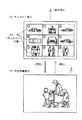
図17(a)は、サムネイル表示例を示している。一般にサムネイル表示を行う場合には、例えばこの図に示すように、1つの表示画面Pを複数の分割表示領域に分割することが行われる。この場合には、1画面を9つの分割表示領域に分割した場合が示されている。ここでは、便宜上、各分割表示領域に対して▲1▼〜▲9▼で示すナンバを付している。
そして、これら分割表示領域に対して、例えばある記録媒体に記録されているとされるファイルごとのサムネイル画像SN,SN,SN・・・を貼り付けるようにして表示していくものとされる。
【0004】
このようにしてサムネイル表示を行うようにすることで、例えばユーザは、その記録媒体に記録されている画像ファイルの内容を視覚的に把握することができ、所望のファイルをより迅速かつ的確に検索することが可能となる。
例えば一般には、上記図17(a)のようにして表示された複数のサムネイル画像SN,SN,SN・・・のなかから、ユーザが所望のファイルに対応するサムネイル画像をカーソル等により選択してクリックなどの操作を行うようにされる。すると、例えば記録媒体から、ユーザが選択したサムネイル画像に対応するファイルの画像データが再生され、例えば図17(b)に示すようにして、表示画面Pに対して通常のサイズで表示されるようになっている。
【0005】
【発明が解決しようとする課題】
ところで、例えば上記図17にて説明したようにして、サムネイル表示としての検索画面に対して操作を行ってファイルを再生表示させるようなユーザインターフェイスとした場合、このファイルの再生が行われている間は、表示画面Pのほぼ全表示領域を使用して再生画像の表示が行われることになる。従って、この間は、表示画面を利用してのファイル検索ができないことになる。
そして、例えば或るファイルを再生しているときに、ユーザが他のファイルを検索したいと思ったとすれば、例えば、これまでのファイル再生を一旦終了させることで、例えば図17(b)に示した再生画面から再度、図17(a)に示したサムネイル表示画面に戻るようにする必要があることになる。つまり、従来においては、ファイル再生画面を表示させると同時にファイル検索を行うことができないものであり、ユーザの使い勝手を考慮すれば、このようなファイル再生画面を表示させながら検索が行えるようにした機能が与えられることが好ましいことになる。
【0006】
【課題を解決するための手段】
そこで本発明は上記した課題を考慮して、画像表示システムとして次のように構成する。
つまり、記録及び/又は再生装置とサーバ装置とから成り、上記記録及び/又は再生装置は、上記サーバ装置とデータの送受信が可能なように通信する通信手段と、サムネイル表示を指示する操作に応じて、上記サーバ装置に対して、このサーバ装置が記憶している画像ファイルのサムネイル画像を要求するコマンドを送信するサムネイル要求手段と、上記サムネイル画像を要求するコマンドに応じて上記サーバ装置から送信されてきたサムネイル画像データを受信して取得するサムネイル画像データ取得手段と、取得した上記サムネイル画像データを利用して、サムネイル画像が一覧表示される上記サムネイル表示を行うサムネイル表示手段と、上記サムネイル表示において表示されているサムネイル画像に対して行われた再生指示操作に応じては、サーバ装置に対して、この再生指示操作が行われたサムネイル画像に対応する画像ファイルの送信を要求するコマンドを送信し、子画面において表示されているサムネイル画像に対して行われた再生指示操作に応じては、記録媒体に記憶されていなければ、サーバ装置に対して、この再生指示操作が行われたサムネイル画像に対応する画像ファイルの送信を要求するコマンドを送信する、画像ファイル要求手段と、上記サーバ装置から送信されてきた画像ファイルを受信して上記記録媒体に記録する記録手段と、上記画像ファイルを主画面に再生表示させる主画面表示手段と、上記再生指示操作に応じて、この上記再生指示操作が行われたサムネイル画像に対応する画像ファイルであり、上記記録媒体に記録済みの画像ファイルを主画面に再生表示する主画面表示手段と、上記画像ファイルが表示される主画面が表示されているときに行われた、サムネイル画像を指定して表示させるためのサムネイル指定表示操作に応じて、上記主画面とともに、取得されたサムネイル画像データのうちから、上記サムネイル指定表示操作により指定されるサムネイル画像データを利用して子画面に表示させる子画面表示手段と、画像ファイルを主画面に再生表示させているときに、この主画面に表示させている画像ファイルを識別する情報を有し、さらに主画面とともに子画面も表示させている状況であれば、子画面に表示されているサムネイル画像に対応する画像ファイルを識別する情報も有した状況通知を上記サーバ装置に対して送信する状況通知送信手段とを備え、上記サーバ装置は、上記記録及び/又は再生装置とデータの送受信が可能なように通信する通信手段と、画像ファイルを記憶している記憶手段と、上記サムネイル画像を要求するコマンドの受信に応じて、上記記録及び/又は再生装置に対して、上記記憶手段が記憶している画像ファイルのサムネイル画像データを送信するサムネイル画像データ送信手段と、上記画像ファイルの送信を要求するコマンドの受信に応じて、上記記録及び/又は再生装置に対して、上記記憶手段が記憶している画像ファイルのうちから要求された画像ファイルを送信する要求対応画像ファイル送信手段と、上記状況通知の受信に応じて上記記憶手段が記憶している画像ファイルを、記録及び/又は再生装置に対して送信するもので、受信した上記状況通知により主画面のみを表示している状況であることが示される場合にには、この主画面に再生表示されている画像ファイルよりも再生順が後となる画像ファイルにおいて、上記記録媒体に記録されてない画像ファイルのうちから最も再生順の若い画像ファイルを送信し、受信した上記状況通知により主画面とともに子画面も表示している状況であることが示される場合には、この子画面に表示されているサムネイル画像に対応する画像ファイルを送信する、状況通知対応画像ファイル送信手段とを備えることとした。
【0007】
また、記録及び/又は再生装置とサーバ装置とから成る画像表示システムにおける画像表示方法として、上記記録及び/又は再生装置においては、上記サーバ装置とデータの送受信が可能なように通信する通信手順と、サムネイル表示を指示する操作に応じて、上記サーバ装置に対して、このサーバ装置が記憶している画像ファイルのサムネイル画像を要求するコマンドを送信するサムネイル要求手順と、上記サムネイル画像を要求するコマンドに応じて上記サーバ装置から送信されてきたサムネイル画像データを受信して取得するサムネイル画像データ取得手順と、取得した上記サムネイル画像データを利用して、サムネイル画像が一覧表示される上記サムネイル表示を行うサムネイル表示手順と、上記サムネイル表示において表示されているサムネイル画像に対して行われた再生指示操作に応じては、サーバ装置に対して、この再生指示操作が行われたサムネイル画像に対応する画像ファイルの送信を要求するコマンドを送信し、子画面において表示されているサムネイル画像に対して行われた再生指示操作に応じては、記録媒体に記憶されていなければ、サーバ装置に対して、この再生指示操作が行われたサムネイル画像に対応する画像ファイルの送信を要求するコマンドを送信する、画像ファイル要求手順と、上記サーバ装置から送信されてきた画像ファイルを受信して上記記録媒体に記録する記録手順と、上記画像ファイルを主画面に再生表示させる主画面表示手順と、上記再生指示操作に応じて、この上記再生指示操作が行われたサムネイル画像に対応する画像ファイルであり、上記記録媒体に記録済みの画像ファイルを主画面に再生表示する主画面表示手順と、上記画像ファイルが表示される主画面が表示されているときに行われた、サムネイル画像を指定して表示させるためのサムネイル指定表示操作に応じて、上記主画面とともに、取得されたサムネイル画像データのうちから、上記サムネイル指定表示操作により指定されるサムネイル画像データを利用して子画面に表示させる子画面表示手順と、
画像ファイルを主画面に再生表示させているときに、この主画面に表示させている画像ファイルを識別する情報を有し、さらに主画面とともに子画面も表示させている状況であれば、子画面に表示されているサムネイル画像に対応する画像ファイルを識別する情報も有した状況通知を上記サーバ装置に対して送信する状況通知送信手順とを実行し、上記サーバ装置は、上記記録及び/又は再生装置とデータの送受信が可能なように通信する通信手順と、上記サムネイル画像を要求するコマンドの受信に応じて、上記記録及び/又は再生装置に対して、このサーバ装置が記憶している画像ファイルのサムネイル画像データを送信するサムネイル画像データ送信手順と、上記画像ファイルの送信を要求するコマンドの受信に応じて、上記記録及び/又は再生装置に対して、このサーバ装置が記憶している画像ファイルのうちから要求された画像ファイルを送信する要求対応画像ファイル送信手順と、上記状況通知の受信に応じて上記記憶手段が記憶している画像ファイルを、記録及び/又は再生装置に対して送信するもので、受信した上記状況通知により主画面のみを表示している状況であることが示される場合にには、この主画面に再生表示されている画像ファイルよりも再生順が後となる画像ファイルにおいて、上記記録媒体に記録されてない画像ファイルのうちから最も再生順の若い画像ファイルを送信し、受信した上記状況通知により主画面とともに子画面も表示している状況であることが示される場合には、この子画面に表示されているサムネイル画像に対応する画像ファイルを送信する、状況通知対応画像ファイル送信手順とを実行することとした。
【0010】
上記各構成によれば、画像についての表示にあたり、1つの表示画面上において、主画面による表示と子画面による表示との2つの表示領域による表示とが同時に行われる。そして主画面の表示領域においては再生出力すべき画像ファイルの再生表示が行われ、子画面においてはサムネイル画像を表示する。そのうえで第2の表示領域に表示されるサムネイル画像の画像ファイルを再生するための操作も可能とされる。
これは、即ち画像ファイルの再生表示と同時に、他の画像ファイルを視覚的に把握し得る情報を表示させているものであり、更に、子画面に対して再生操作が行えることを意味する。
【0011】
【発明の実施の形態】
以下、本発明の実施の形態について説明していく。
本実施の形態の記録及び/又は再生装置としては、カメラ装置部と画像(静止画又は動画)及び音声等の記録再生が可能な記録再生装置部とが一体化された可搬型のビデオカメラに搭載されている場合を例にあげる。また、本実施の形態のビデオカメラに搭載される記録再生装置部は、光磁気ディスクの一種として知られている、いわゆるミニディスクに対応してデータを記録再生する構成を採るものとされる。
説明は次の順序で行う。
1.ディスクフォーマット
2.ビデオカメラの外観構成
3.ビデオカメラの内部構成
4.メディアドライブ部の構成
5.本実施の形態に対応するディスク構造例
6.サムネイル画像生成処理
7.スクリプト
8.操作画面表示
9.本実施の形態のファイル検索機能
9−1.第1例
9−2.第2例
【0012】
1.ディスクフォーマット
本例のビデオカメラに搭載される記録再生装置部は、ミニディスク(光磁気ディスク)に対応してデータの記録/再生を行う、MDデータといわれるフォーマットに対応しているものとされる。このMDデータフォーマットとしては、MD−DATA1とMD−DATA2といわれる2種類のフォーマットが開発されているが、本例のビデオカメラは、MD−DATA1よりも高密度記録が可能とされるMD−DATA2のフォーマットに対応して記録再生を行うものとされている。そこで、先ずMD−DATA2のディスクフォーマットについて説明する。
【0013】
図1及び図2は、MD−DATA2としてのディスクのトラック構造例を概念的に示している。図2(a)(b)は、それぞれ図1の破線Aで括った部分を拡大して示す断面図及び平面図である。
これらの図に示すように、ディスク面に対してはウォブル(蛇行)が与えられたウォブルドグルーブWGと、ウォブルが与えられていないノンウォブルドグルーブNWGとの2種類のグルーブ(溝)が予め形成される。そして、これらウォブルドグルーブWGとノンウォブルドグルーブNWGは、その間にランドLdを形成するようにしてディスク上において2重のスパイラル状に存在する。
【0014】
MD−DATA2フォーマットでは、ランドLdが記録トラック(データが記録されるトラック)として利用されるのであるが、上記のようにしてウォブルドグルーブWGとノンウォブルドグルーブNWGが形成されることから、記録トラックとしてもトラックTr・A,Tr・Bの2つのトラックがそれぞれ独立して、2重のスパイラル(ダブルスパイラル)状に形成されることになる。
トラックTr・Aは、ディスク外周側にウォブルドグルーブWGが位置し、ディスク内周側にノンウォブルドグルーブNWGが位置するトラックとなる。
これに対してトラックTr・Bは、ディスク内周側にウォブルドグルーブWGが位置し、ディスク外周側にノンウォブルドグルーブNWGが位置するトラックとなる。
つまり、トラックTr・Aに対してはディスク外周側の片側のみにウォブルが形成され、トラックTr・Bとしてはディスク内周側の片側のみにウォブルが形成されるようにしたものとみることができる。
この場合、トラックピッチは、互いに隣接するトラックTr・AとトラックTr・Bの各センター間の距離となり、図2(b)に示すようにトラックピッチは0.95μmとされている。
【0015】
ここで、ウォブルドグルーブWGとしてのグルーブに形成されたウォブルは、ディスク上の物理アドレスがFM変調+バイフェーズ変調によりエンコードされた信号に基づいて形成されているものである。このため、記録再生時においてウォブルドグルーブWGに与えられたウォブリングから得られる再生情報を復調処理することで、ディスク上の物理アドレスを抽出することが可能となる。
また、ウォブルドグルーブWGとしてのアドレス情報は、トラックTr・A,Tr・Bに対して共通に有効なものとされる。つまり、ウォブルドグルーブWGを挟んで内周に位置するトラックTr・Aと、外周に位置するトラックTr・Bは、そのウォブルドグルーブWGに与えられたウォブリングによるアドレス情報を共有するようにされる。
なお、このようなアドレッシング方式はインターレースアドレッシング方式ともいわれる。このインターレースアドレッシング方式を採用することで、例えば、隣接するウォブル間のクロストークを抑制した上でトラックピッチを小さくすることが可能となるものである。また、グルーブに対してウォブルを形成することでアドレスを記録する方式については、ADIP(Adress In Pregroove) 方式ともいう。
【0016】
また、上記のようにして同一のアドレス情報を共有するトラックTr・A,Tr・Bの何れをトレースしているのかという識別は次のようにして行うことができる。
例えば3ビーム方式を応用し、メインビームがトラック(ランドLd)をトレースしている状態では、残る2つのサイドビームは、上記メインビームがトレースしているトラックの両サイドに位置するグルーブをトレースしているようにすることが考えられる。
【0017】
図2(b)には、具体例として、メインビームスポットSPmがトラックTr・Aをトレースしている状態が示されている。この場合には、2つのサイドビームスポットSPs1,SPs2のうち、内周側のサイドビームスポットSPs1はノンウォブルドグルーブNWGをトレースし、外周側のサイドビームスポットSPs2はウォブルドグルーブWGをトレースすることになる。
これに対して、図示しないが、メインビームスポットSPmがトラックTr・Bをトレースしている状態であれば、サイドビームスポットSPs1がウォブルドグルーブWGをトレースし、サイドビームスポットSPs2がノンウォブルドグルーブNWGをトレースすることになる。
このように、メインビームスポットSPmが、トラックTr・Aをトレースする場合とトラックTr・Bをトレースする場合とでは、サイドビームスポットSPs1,SPs2がトレースすべきグルーブとしては、必然的にウォブルドグルーブWGとノンウォブルドグルーブNWGとで入れ替わることになる。
【0018】
サイドビームスポットSPs1,SPs2の反射によりフォトディテクタにて得られる検出信号としては、ウォブルドグルーブWGとノンウォブルドグルーブNWGの何れをトレースしているのかで異なる波形が得られることから、上記検出信号に基づいて、例えば、現在サイドビームスポットSPs1,SPs2のうち、どちらがウォブルドグルーブWG(あるいはノンウォブルドグルーブNWG)をトレースしているのかを判別することにより、メインビームがトラックTr・A,Tr・Bのどちらをトレースしているのかが識別できることになる。
【0019】
図3は、上記のようなトラック構造を有するMD−DATA2フォーマットのの主要スペックをMD−DATA1フォーマットと比較して示す図である。
先ず、MD−DATA1フォーマットとしては、トラックピッチは1.6μm、ピット長は0.59μm/bitとなる。また、レーザ波長λ=780nmとされ、光学ヘッドの開口率NA=0.45とされる。
記録方式としては、グルーブ記録方式を採っている。つまり、グルーブをトラックとして記録再生に用いるようにしている。
アドレス方式としては、シングルスパイラルによるグルーブ(トラック)を形成したうえで、このグルーブの両側に対してアドレス情報としてのウォブルを形成したウォブルドグルーブを利用する方式を採るようにされている。
【0020】
記録データの変調方式としてはEFM(8−14変換)方式を採用している。また、誤り訂正方式としてはACIRC(Advanced Cross Interleave Reed-Solomon Code) が採用され、データインターリーブには畳み込み型を採用している。このため、データの冗長度としては46.3%となる。
【0021】
また、MD−DATA1フォーマットでは、ディスク駆動方式としてCLV(Constant Linear Verocity)が採用されており、CLVの線速度としては、1.2m/sとされる。
そして、記録再生時の標準のデータレートとしては、133kB/sとされ、記録容量としては、140MBとなる。
【0022】
これに対して、本例のビデオカメラが対応できるMD−DATA2フォーマットとしては、トラックピッチは0.95μm、ピット長は0.39μm/bitとされ、共にMD−DATA1フォーマットよりも短くなっていることが分かる。そして、例えば上記ピット長を実現するために、レーザ波長λ=650nm、光学ヘッドの開口率NA=0.52として、合焦位置でのビームスポット径を絞ると共に光学系としての帯域を拡げている。
【0023】
記録方式としては、図1及び図2により説明したように、ランド記録方式が採用され、アドレス方式としてはインターレースアドレッシング方式が採用される。また、記録データの変調方式としては、高密度記録に適合するとされるRLL(1,7)方式(RLL;Run Length Limited)が採用され、誤り訂正方式としてはRS−PC方式、データインターリーブにはブロック完結型が採用される。そして、上記各方式を採用した結果、データの冗長度としては、19.7%にまで抑制することが可能となっている。
【0024】
MD−DATA2フォーマットにおいても、ディスク駆動方式としてはCLVが採用されるのであるが、その線速度としては2.0m/sとされ、記録再生時の標準のデータレートとしては589kB/sとされる。そして、記録容量としては650MBを得ることができ、MD−DATA1フォーマットと比較した場合には、4倍強の高密度記録化が実現されたことになる。
例えば、MD−DATA2フォーマットにより動画像の記録を行うとして、動画像データについてMPEG2による圧縮符号化を施した場合には、符号化データのビットレートにも依るが、時間にして15分〜17分の動画を記録することが可能とされる。また、音声信号データのみを記録するとして、音声データについてATRAC(Adaptve Transform Acoustic Coding) 2による圧縮処理を施した場合には、時間にして10時間程度の記録を行うことができる。
【0025】
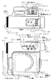
2.ビデオカメラの外観構成
次に本例のビデオカメラの外観例について説明しておく。
図6(a)(b)、図7(a)(b)は、それぞれ、本例のビデオカメラの平面図、側面図、正面図、背面図である。
これらの図に示すように、本例のビデオカメラの本体200の正面部には、撮影を行うための撮像レンズや絞りなどを備えたカメラレンズ201が表出するようにして設けられる。また、同じ本体200の背面部下側には、撮影時において外部の音声を収音するためのマイクロフォン202が設けられている。つまり、このビデオカメラでは、カメラレンズ201により撮影した画像の録画と、マイクロフォン202により収音したステレオ音声の録音を行うことが可能とされている。また、ここでは、マイクロフォン202と同じ位置に再生音声を出力するためのスピーカ205も備えられているものとしている。また、スピーカ205からはビープ音等による所要のメッセージ音も出力される。
【0026】
また、本体200の背面側には、ビューファインダ204が設けられており、記録動作中及びスタンバイ中等においては、カメラレンズ201から取り込まれる画像(スルー画ともいう)及びキャラクタ画像等が表示される。ユーザーはこのビューファインダ204をみながら撮影を行うことができる。
また、後述するメインダイヤル300、レリーズキー301、削除キー302が設けられた部位は電池蓋部206として開閉可能となっており、この電池蓋部206を開くことで、バッテリ(充電池)を装脱することが可能となっている。
【0027】
また、本体200の側面側には、可動パネル部203が備えられている。この可動支持部208によって支持されていることで、本体200に対して可動可能に取り付けられている。この可動パネル部203の動きについては後述する。
【0028】
また、可動パネル部203の背面側には表示パネル67(表示画面)が設けられている。従って、図6(b)に示すように可動パネル部203が収納状態にあるときは、表示パネル67は本体側に向いて格納される状態となる。
【0029】
表示パネル67は、撮影画像、及び内部の記録再生装置により再生された画像等を表示出力するための部位とされる。また、機器の動作に応じて所要のメッセージをユーザに知らせるための文字やキャラクタ等によるメッセージ表示等も行われる。なお、この表示パネル67として実際に採用する表示デバイスは、ここでは特に限定されるものではないが、例えば液晶ディスプレイ等が用いられればよい。
また、表示パネル67は、例えば液晶ディスプレイの表示面の背面側に対して、押圧操作を関知してこれを操作情報として出力するタッチパネルが設けられている。つまり、本実施の形態にあっては、表示パネル67に表示された画像に対して押圧操作を行う、いわゆるGUIとしての操作が可能とされる。
ここで、表示パネル67に対する操作としては、タッチパネルに対して押圧力が加わった位置を座標位置情報として検知する構成とされていることから、指などによって操作されてもよいのものとされる。しかし、表示パネル67の表示面積に制限があって、そのポインティングの操作も指では困難な場合があることを考慮して、図6(b)に示すように、スティック形状のペン320が添え付けされる。ユーザは、指の代わりにこのペン320を使用して表示パネル67に対するポインティング(タッチ)操作を行うことができる。
【0030】
また、可動パネル部203が収納される本体部200側の部位がディスク装脱部205となっており、このディスク装脱部205において、本例のビデオカメラが対応する記録媒体としてのディスクを挿入、あるいは排出させることができる。
【0031】
また、ここでは図示していないが、実際には、外部の映像機器に対して再生画像信号等を出力するビデオ出力端子や、外部の音声機器やヘッドホンに対して再生音声信号を出力するヘッドフォン/ライン端子等が設けられている。また、外部のデータ機器とデータ伝送を行うためのインターフェイス機能に対応してI/F端子等も設けられている。
【0032】
さらに、本体200の各部には、ユーザー操作のための各種の操作子が設けられる。以下、主要となる各操作子について説明する。
メインダイヤル300は、図7(b)に示されるようにして本体200の背面側に設けられ、ビデオカメラのオン/オフ、記録動作、再生動作を設定する操作子とされる。この場合には、回転操作が行えるものとなっている。
メインダイヤル300が電源オフ位置PS2にある場合には電源がオフの状態にある。そして、例えばこの状態からメインダイヤル300を回転操作して再生/編集位置PS1とすれば、電源オンの状態となって、録画ファイルの再生や、各種編集操作が可能なモード状態となる。また、カメラモード位置PS2とすれば、電源オンの状態で、動画、又は静止画としての録画ファイルを記録可能なモード(カメラモード)となる。更に、カメラモード位置PS2とすれば、インタビューモードとなる。
インタビューモードとは、ここでは詳しい説明は省略するが、記録動作としては、音声主体で記録を行って、任意の時点で、後述するレリーズキー301又はフォトキー304を押圧操作すれば、その時点で撮影されている画像を静止画として記録するモードである。そして、インタビューモードの再生では、このインタビューモードによって記録された録画ファイルを再生するものである。このときには、例えば音声を再生しながら記録時のタイミングで、静止画を切り換えるようにして表示させていく。
【0033】
また、メインダイヤル300の回転部中央には、レリーズキー301が備えられる。
このレリーズキー301は、カメラモード又はインタビューモードにある状態で記録開始/終了のための操作子として機能するものである。
【0034】
また、本体200背面部にはジョグダイヤル303も設けられる。ジョグダイヤル303は、円盤状の操作子とされ、正/逆方向に回転操作可能に取り付けられていると共に、所定の回転角度ごとにクリック感が得られるようになっている。ここでは、図7(b)において示される、矢印マーク303aの上側方向に沿う回転方向が正方向となり、下側方向に沿う回転方向が逆方向となる。また、この場合のジョグダイヤル311は、図7(b)において矢印マーク303bが示す左方向に対して押圧操作が行えるようにもなっている。
このジョグダイヤル303は、例えば実際には、例えば2相式のロータリエンコーダなどと組み合わされることで、例えば1クリックが1回転ステップとなるようにして、その回転方向と回転角度に対応した回転ステップ数の情報を出力する。
【0035】
削除キー302は、所定のモードで再生されているデータについて、削除を行うための決定キーとして機能する。
【0036】
また、主としては図6(a)に示されるように、本体200側面部においてはやや上向きの状態でフォトキー304、ズームキー305,フォーカスキー306,及び逆光補正キー307が備えられる。
フォトキー304は、例えばカメラモードの状態で押圧操作することで静止画の録画ファイルを記録するためのシャッターとして機能する操作子である。
【0037】
ズームキー305は、レンズ光学系(カメラレンズ201)におけるズーム状態(テレ側〜ワイド側)を操作する操作子である。
フォーカスキー306は、レンズ光学系のフォーカス状態(例えばノーマル/無限など)を切り換えるための操作子である。
逆光補正キー307は、逆光補正機能をオン/オフするための操作子である。
【0038】
また、図6(b)に示すようにして、可動パネル部203が配置される側の本体200側面部には、主としてファイル(トラック)の記録再生に関するキーとして、再生/ポーズキー308、停止キー309、スロー再生キー310、サーチキー311,312、録音キー313が設けられる。
また、図6(a)に示すように、本体200の上面部には、画面表示のための画面表示キー314と、スピーカからの出力音声の音量調節のための音量キー315,316が設けられる。
【0039】
なお、上記図6及び図7に示すビデオカメラの外観はあくまでも一例であって、実際に本例のビデオカメラに要求される使用条件等に応じて適宜変更されて構わないものである。もちろん操作子の種類や操作方式、さらに外部機器との接続端子類などは各種多様に考えられる。
【0040】
また、図8により、先に述べた可動パネル部203の動き方について説明しておく。なお、図8にあっては、説明の便宜上、ビデオカメラの外観は簡略化して示している。
可動パネル部203の動きとしては、先ず、図6(b)に示した位置状態から図8(a)に示すようにして矢印YJ1の方向に沿って引き起こすようにしてその位置状態を変えることができるようになっている。
この場合、表示画面(表示パネル67)は撮影者(ビューファインダ204)側に向くようにされ、撮像画像を捉えるカメラレンズ201とはほぼ対向する方向を向くことになる。この表示パネルの位置状態では、例えばビデオカメラを所持する撮影者が表示パネル67に表示された撮像画像をモニタしながら撮影(録画)を行うことができる。
【0041】
また、上記図8(a)に示す状態から矢印YJ2の方向に沿って約180°程度の範囲で可動パネル部203を回転させることができるようになっている。つまり、図8(b)に示すようにして、表示パネル67が被写体(カメラレンズ)側を向く位置状態とすることができる。
この状態では、被写体側にいるユーザが撮像画像を見ることができることになる。
ディスク装脱部205に対してディスクの挿入を行ったり、ディスクの取り出しを行ったりする場合には、この図8(a)(b)に示すようにして、本体200から可動パネル部203を起こした状態で行うようにされる。
【0042】
また、図8(b)に示す状態から矢印YJ3の方向に可動パネル部203を動かすこともできる。このようにすれば、図示はしないが、表示パネル67が外側から見える状態で、可動パネル部203が収納位置にあるようにされることになる。
【0043】
なお、上述のようにして矢印YJ2の方向に沿って表示パネルを回転させると、表示パネル67が撮影者側に向いたときと被写体側に向いたときとでは、そのままでは表示画像の見え方が上下左右で反転することになるが、本実施の形態では、可動パネル部203の回動状態に応じて、表示パネル67の表示画像が常にユーザ(撮影者及び被写体)から適正な方向で見えるように反転表示制御を行うことでこのような不都合を解消している。
【0044】
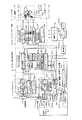
3.ビデオカメラの内部構成
図4は、本例のビデオカメラの内部構成例を示すブロック図である。
この図に示すレンズブロック1においては、例えば実際には撮像レンズや絞りなどを備えて構成される光学系11が備えられている。上記図6に示したカメラレンズ201は、この光学系11に含まれる。また、このレンズブロック1には、光学系11に対してオートフォーカス動作を行わせるためのフォーカスモータや、上記ズームキー304の操作に基づくズームレンズの移動を行うためのズームモータなどが、モータ部12として備えられる。
【0045】
カメラブロック2には、主としてレンズブロック1により撮影した画像光をデジタル画像信号に変換するための回路部が備えられる。
このカメラブロック2のCCD(Charge Coupled Device) 21に対しては、光学系11を透過した被写体の光画像が与えられる。CCD21においては上記光画像について光電変換を行うことで撮像信号を生成し、サンプルホールド/AGC(Automatic Gain Control)回路22に供給する。サンプルホールド/AGC回路22では、CCD21から出力された撮像信号についてゲイン調整を行うと共に、サンプルホールド処理を施すことによって波形整形を行う。サンプルホールド/AGC回路2の出力は、ビデオA/Dコンバータ23に供給されることで、デジタルとしての画像信号データに変換される。
【0046】
上記CCD21、サンプルホールド/AGC回路22、ビデオA/Dコンバータ23における信号処理タイミングは、タイミングジェネレータ24にて生成されるタイミング信号により制御される。タイミングジェネレータ24では、後述するデータ処理/システムコントロール回路31(ビデオ信号処理回部3内)にて信号処理に利用されるクロックを入力し、このクロックに基づいて所要のタイミング信号を生成するようにされる。これにより、カメラブロック2における信号処理タイミングを、ビデオ信号処理部3における処理タイミングと同期させるようにしている。
カメラコントローラ25は、カメラブロック2内に備えられる上記各機能回路部が適正に動作するように所要の制御を実行すると共に、レンズブロック1に対してオートフォーカス、自動露出調整、絞り調整、ズームなどのための制御を行うものとされる。
例えばオートフォーカス制御であれば、カメラコントローラ25は、所定のオートフォーカス制御方式に従って得られるフォーカス制御情報に基づいて、フォーカスモータの回転角を制御する。これにより、撮像レンズはジャストピント状態となるように駆動されることになる。
【0047】
ビデオ信号処理部3は、記録時においては、カメラブロック2から供給されたデジタル画像信号、及びマイクロフォン202により集音したことで得られるデジタル音声信号について圧縮処理を施し、これら圧縮データをユーザ記録データとして後段のメディアドライブ部4に供給する。さらにカメラブロック2から供給されたデジタル画像信号とキャラクタ画像により生成した画像をビューファインダドライブ部207に供給し、ビューファインダ204に表示させる。
また、再生時においては、メディアドライブ部4から供給されるユーザ再生データ(ディスク51からの読み出しデータ)、つまり圧縮処理された画像信号データ及び音声信号データについて復調処理を施し、これらを再生画像信号、再生音声信号として出力する。
【0048】
なお本例において、画像信号データ(画像データ)の圧縮/伸張処理方式としては、動画像についてはMPEG(Moving Picture Experts Group)2を採用し、静止画像についてはJPEG(Joint Photographic Coding Experts Group) を採用しているものとする。また、音声信号デーのタ圧縮/伸張処理方式には、ATRAC(Adaptve Transform Acoustic Coding) 2を採用するものとする。
【0049】
ビデオ信号処理部3のデータ処理/システムコントロール回路31は、主として、当該ビデオ信号処理部3における画像信号データ及び音声信号データの圧縮/伸張処理に関する制御処理と、ビデオ信号処理部3を経由するデータの入出力を司るための処理を実行する。
また、データ処理/システムコントロール回路31を含むビデオ信号処理部3全体についての制御処理は、ビデオコントローラ38が実行するようにされる。このビデオコントローラ38は、例えばマイクロコンピュータ等を備えて構成され、カメラブロック2のカメラコントローラ25、及び後述するメディアドライブ部4のドライバコントローラ46と、例えば図示しないバスライン等を介して相互通信可能とされている。即ち、ビデオコントローラ38はシステム全体を制御するマスターコントローラとして機能する。
【0050】
また、ビデオコントローラ38に対してはプログラムメモリ39が備えられる。
このプログラムメモリ39は、例えばEEPROMやフラッシュメモリなどの書き換え可能な記憶素子により構成され、ここにはマスターコントローラであるビデオコントローラ38が実行すべき各種プログラムを始めとし、各種設定データなどの情報が格納される。
【0051】
ビデオ信号処理部3における記録時の基本的な動作として、データ処理/システムコントロール回路31には、カメラブロック2のビデオA/Dコンバータ23から供給された画像信号データが入力される。データ処理/システムコントロール回路31では、入力された画像信号データを例えば動き検出回路35に供給する。動き検出回路35では、例えばメモリ36を作業領域として利用しながら入力された画像信号データについて動き補償等の画像処理を施した後、MPEG2ビデオ信号処理回路33に供給する。
【0052】
MPEG2ビデオ信号処理回路33においては、例えばメモリ34を作業領域として利用しながら、入力された画像信号データについてMPEG2のフォーマットに従って圧縮処理を施し、動画像としての圧縮データのビットストリーム(MPEG2ビットストリーム)を出力するようにされる。また、MPEG2ビデオ信号処理回路33では、例えば動画像としての画像信号データから静止画としての画像データを抽出してこれに圧縮処理を施す際には、JPEGのフォーマットに従って静止画としての圧縮画像データを生成するように構成されている。なお、JPEGは採用せずに、MPEG2のフォーマットによる圧縮画像データとして、正規の画像データとされるIピクチャ(Intra Picture) を静止画の画像データとして扱うことも考えられる。
MPEG2ビデオ信号処理回路33により圧縮符号化された画像信号データ(圧縮画像データ)は、例えば、バッファメモリ32に対して所定の転送レートにより書き込まれて一時保持される。
なおMPEG2のフォーマットにおいては、周知のようにいわゆる符号化ビットレート(データレート)として、一定速度(CBR;Constant Bit Rate)と、可変速度(VBR;Variable Bit Rate)の両者がサポートされており、ビデオ信号処理部3ではこれらに対応できるものとしている。
【0053】
例えばVBRによる画像圧縮処理を行う場合には、例えば、動き検出回路35において、画像データをマクロブロック単位により前後数十〜数百フレーム内の範囲で動き検出を行って、動きありとされればこの検出結果を動きベクトル情報としてMPEG2ビデオ信号処理回路33に伝送する。
MPEG2ビデオ信号処理回路33では、圧縮符号化後の画像データをある所要のデータレートとするように、上記動きベクトル情報をはじめとする所要の情報を利用しながら、マクロブロックごとの量子化係数を決定していくようにされる。
【0054】
音声圧縮エンコーダ/デコーダ37には、A/Dコンバータ64(表示/画像/音声入出力部6内)を介して、例えばマイクロフォン202により集音された音声がデジタルによる音声信号データとして入力される。
音声圧縮エンコーダ/デコーダ37では、前述のようにATRAC2のフォーマットに従って入力された音声信号データに対する圧縮処理を施す。この圧縮音声信号データもまた、データ処理/システムコントロール回路31によってバッファメモリ32に対して所定の転送レートによる書き込みが行われ、ここで一時保持される。
【0055】
上記のようにして、バッファメモリ32には、圧縮画像データ及び圧縮音声信号データが蓄積可能とされる。バッファメモリ32は、主として、カメラブロック2あるいは表示/画像/音声入出力部6とバッファメモリ32間のデータ転送レートと、バッファメモリ32とメディアドライブ部4間のデータ転送レートの速度差を吸収するための機能を有する。
バッファメモリ32に蓄積された圧縮画像データ及び圧縮音声信号データは、記録時であれば、順次所定タイミングで読み出しが行われて、メディアドライブ部4のMD−DATA2エンコーダ/デコーダ41に伝送される。ただし、例えば再生時においてバッファメモリ32に蓄積されたデータの読み出しと、この読み出したデータをメディアドライブ部4からデッキ部5を介してディスク51に記録するまでの動作は、間欠的に行われても構わない。
このようなバッファメモリ32に対するデータの書き込み及び読み出し制御は、例えば、データ処理/システムコントロール回路31によって実行される。
【0056】
ビデオ信号処理部3における再生時の動作としては、概略的に次のようになる。
再生時には、ディスク51から読み出され、MD−DATA2エンコーダ/デコーダ41(メディアドライブ部4内)の処理によりMD−DATA2フォーマットに従ってデコードされた圧縮画像データ、圧縮音声信号データ(ユーザ再生データ)が、データ処理/システムコントロール回路31に伝送されてくる。
データ処理/システムコントロール回路31では、例えば入力した圧縮画像データ及び圧縮音声信号データを、一旦バッファメモリ32に蓄積させる。そして、例えば再生時間軸の整合が得られるようにされた所要のタイミング及び転送レートで、バッファメモリ32から圧縮画像データ及び圧縮音声信号データの読み出しを行い、圧縮画像データについてはMPEG2ビデオ信号処理回路33に供給し、圧縮音声信号データについては音声圧縮エンコーダ/デコーダ37に供給する。
【0057】
MPEG2ビデオ信号処理回路33では、入力された圧縮画像データについて伸張処理を施して、データ処理/システムコントロール回路31に伝送する。データ処理/システムコントロール回路31では、この伸張処理された画像信号データを、ビデオD/Aコンバータ61(表示/画像/音声入出力部6内)に供給する。
音声圧縮エンコーダ/デコーダ37では、入力された圧縮音声信号データについて伸張処理を施して、D/Aコンバータ65(表示/画像/音声入出力部6内)に供給する。
【0058】
表示/画像/音声入出力部6においては、ビデオD/Aコンバータ61に入力された画像信号データは、ここでアナログ画像信号に変換され、表示コントローラ62及びコンポジット信号処理回路63に対して分岐して入力される。
表示コントローラ62では、入力された画像信号に基づいて表示部6Aを駆動する。これにより、表示部6Aにおいて再生画像の表示が行われる。また、表示部6Aにおいては、ディスク51から再生して得られる画像の表示だけでなく、当然のこととして、レンズブロック1及びカメラブロック2からなるカメラ部位により撮影して得られた撮像画像も、ほぼリアルタイムで表示出力させることが可能である。
また、再生画像及び撮像画像の他、前述のように、機器の動作に応じて所要のメッセージをユーザに知らせるための文字やキャラクタ等によるメッセージ表示も行われるものとされる。このようなメッセージ表示は、例えばビデオコントローラ38の制御によって、所要の文字やキャラクタ等が所定の位置に表示されるように、データ処理/システムコントロール回路31からビデオD/Aコンバータ61に出力すべき画像信号データに対して、所要の文字やキャラクタ等の画像信号データを合成する処理を実行するようにすればよい。
【0059】
また、表示部6Aに対しては、タッチパネル6Bが組み合わされることで、表示パネル67を構成する。
タッチパネル6Bでは、表示部6A上に対して行われた押圧操作の位置情報を検知し、これを操作情報としてビデオコントローラ38に対して出力する。
【0060】
コンポジット信号処理回路63では、ビデオD/Aコンバータ61から供給されたアナログ画像信号についてコンポジット信号に変換して、ビデオ出力端子T1に出力する。例えば、ビデオ出力端子T1を介して、外部モニタ装置等と接続を行えば、当該ビデオカメラで再生した画像を外部モニタ装置により表示させることが可能となる。
【0061】
また、表示/画像/音声入出力部6において、音声圧縮エンコーダ/デコーダ37からD/Aコンバータ65に入力された音声信号データは、ここでアナログ音声信号に変換され、ヘッドフォン/ライン端子T2に対して出力される。また、D/Aコンバータ65から出力されたアナログ音声信号は、アンプ66を介してスピーカ205に対しても分岐して出力され、これにより、スピーカ205からは、再生音声等が出力されることになる。
【0062】
メディアドライブ部4では、主として、記録時にはMD−DATA2フォーマットに従って記録データをディスク記録に適合するようにエンコードしてデッキ部5に伝送し、再生時においては、デッキ部5においてディスク51から読み出されたデータについてデコード処理を施すことで再生データを得て、ビデオ信号処理部3に対して伝送する。
【0063】
このメディアドライブ部4のMD−DATA2エンコーダ/デコーダ41は、記録時においては、データ処理/システムコントロール回路31から記録データ(圧縮画像データ+圧縮音声信号データ)が入力され、この記録データについて、MD−DATA2フォーマットに従った所定のエンコード処理を施し、このエンコードされたデータを一時バッファメモリ42に蓄積する。そして、所要のタイミングで読み出しを行いながらデッキ部5に伝送する。
【0064】
再生時においては、ディスク51から読み出され、RF信号処理回路44、二値化回路43を介して入力されたデジタル再生信号について、MD−DATA2フォーマットに従ったデコード処理を施して、再生データとしてビデオ信号処理部3のデータ処理/システムコントロール回路31に対して伝送する。
なお、この際においても、必要があれば再生データを一旦バッファメモリ42に蓄積し、ここから所要のタイミングで読み出したデータをデータ処理/システムコントロール回路31に伝送出力するようにされる。このような、バッファメモリ42に対する書き込み/読み出し制御はドライバコントローラ46が実行するものとされる。
なお、例えばディスク51の再生時において、外乱等によってサーボ等が外れて、ディスクからの信号の読み出しが不可となったような場合でも、バッファメモリ42に対して読み出しデータが蓄積されている期間内にディスクに対する再生動作を復帰させるようにすれば、再生データとしての時系列的連続性を維持することが可能となる。
【0065】
RF信号処理回路44には、ディスク51からの読み出し信号について所要の処理を施すことで、例えば、再生データとしてのRF信号、デッキ部5に対するサーボ制御のためのフォーカスエラー信号、トラッキングエラー信号等のサーボ制御信号を生成する。RF信号は、上記のように二値化回路43により2値化され、デジタル信号データとしてMD−DATA2エンコーダ/デコーダ41に入力される。
また、生成された各種サーボ制御信号はサーボ回路45に供給される。サーボ回路45では、入力したサーボ制御信号に基づいて、デッキ部5における所要のサーボ制御を実行する。
【0066】
なお、本例においては、MD−DATA1フォーマットに対応するエンコーダ/デコーダ47を備えており、ビデオ信号処理部3から供給された記録データを、MD−DATA1フォーマットに従ってエンコードしてディスク51に記録すること、或いは、ディスク51からの読み出しデータがMD−DATA1フォーマットに従ってエンコードされているものについては、そのデコード処理を行って、ビデオ信号処理部3に伝送出力することも可能とされている。つまり本例のビデオカメラとしては、MD−DATA2フォーマットとMD−DATA1フォーマットとについて互換性が得られるように構成されている。
ドライバコントローラ46は、メディアドライブ部4を総括的に制御するための機能回路部とされる。
【0067】
デッキ部5は、ディスク51を駆動するための機構からなる部位とされる。ここでは図示しないが、デッキ部5においては、装填されるべきディスク51が着脱可能とされ、ユーザの作業によって交換が可能なようにされた機構(ディスクスロット203(図6参照))を有しているものとされる。また、ここでのディスク51は、MD−DATA2フォーマット、あるいはMD−DATA1フォーマットに対応する光磁気ディスクであることが前提となる。
【0068】
デッキ部5においては、装填されたディスク51をCLVにより回転駆動するスピンドルモータ52によって、CLVにより回転駆動される。このディスク51に対しては記録/再生時に光学ヘッド53によってレーザ光が照射される。
光学ヘッド53は、記録時には記録トラックをキュリー温度まで加熱するための高レベルのレーザ出力を行ない、また再生時には磁気カー効果により反射光からデータを検出するための比較的低レベルのレーザ出力を行なう。このため、光学ヘッド53には、ここでは詳しい図示は省略するがレーザ出力手段としてのレーザダイオード、偏光ビームスプリッタや対物レンズ等からなる光学系、及び反射光を検出するためのディテクタが搭載されている。光学ヘッド53に備えられる対物レンズとしては、例えば2軸機構によってディスク半径方向及びディスクに接離する方向に変位可能に保持されている。
【0069】
また、ディスク51を挟んで光学ヘッド53と対向する位置には磁気ヘッド54が配置されている。磁気ヘッド54は記録データによって変調された磁界をディスク51に印加する動作を行なう。
また、図示しないが、デッキ部5においては、スレッドモータ55により駆動されるスレッド機構が備えられている。このスレッド機構が駆動されることにより、上記光学ヘッド53全体及び磁気ヘッド54はディスク半径方向に移動可能とされている。
【0070】
操作部7は図6に示した各種操作子に相当し、これらの操作子によるユーザの各種操作情報は例えばビデオコントローラ38に出力される。
ビデオコントローラ38は、先に述べたタッチパネル6B、及び上記操作部7から出力される操作情報に応じた必要な動作が各部において実行されるようにするための制御情報をカメラコントローラ25、ドライバコントローラ46に対して供給する。
【0071】
外部インターフェイス8は、当該ビデオカメラと外部機器とでデータを相互伝送可能とするために設けられており、例えば図のようにI/F端子T3とビデオ信号処理部間に対して設けられる。
【0072】
本実施の形態の場合、この外部インターフェイス8としては、LAN(Local area Network)に広く利用されるEthernetが採用されるものとする。周知のように、Ethernetは、伝送路が1本とされて構造も簡単で安価であり、LAN等を構築するのに適している。また、外部インターフェイス8がEthernetに対応する場合、通信プロトコルとしては、IP(Internet Protocol)が採用されるものとする。そして、I/F端子T3はEthernetに対応するケーブルのコネクタに対応した端子形状を有して備えられる。
【0073】
例えば本実施の形態のビデオカメラをI/F端子T3を介して、Ethernetの伝送路と接続すれば、その伝送路に接続されたパーソナルコンピュータ装置や、他のデジタル画像機器と通信を行い、画像/音声データ等の送受信を行うことが可能になる。また、構成によっては、Ethernetを介して接続された機器から本実施の形態のビデオカメラをリモート制御することも可能となる。
【0074】
また、ここでの詳しい説明は省略するが、パーソナルコンピュータ装置に対して、Ethernetの伝送路を介して、例えばサムネイル表示のためのサムネイル画像データを送信出力する場合、本実施の形態では、HTML形式のWebファイルとして作成されたサムネイル表示画像を出力することができるようになっている。このために、例えばプログラムメモリ39には、このHTML形式によるWebファイルとしてのデータを生成するためのセット(プログラム)も格納されているものである。
【0075】
なお、本実施の形態のビデオカメラとしては、外部とデータの授受を行うためのインターフェイスは、上記Ethernetの他にも、例えばIEEE1394インターフェイスなど、適宜必要に応じて追加されて構わない。つまり、この図に示す外部インターフェイス8としては、実際に設けられるインターフェイス機能の数に応じて、それぞれ異なる規格のインターフェイス部が複数系統設けられてもよいものである。
【0076】
電源ブロック9は、内蔵のバッテリにより得られる直流電源あるいは商用交流電源から生成した直流電源を利用して、各機能回路部に対して所要のレベルの電源電圧を供給する。電源ブロック9による電源オン/オフは、上述したメインダイヤル300の操作に応じてビデオコントローラ38が制御する。
また記録動作中はビデオコントローラ38はインジケータ206の発光動作を実行させる。
【0077】
4.メディアドライブ部の構成
続いて、図4に示したメディアドライブ部4の構成として、MD−DATA2に対応する機能回路部を抽出した詳細な構成について、図5のブロック図を参照して説明する。なお、図5においては、メディアドライブ部4と共にデッキ部5を示しているが、デッキ部5の内部構成については図4により説明したため、ここでは、図4と同一符号を付して説明を省略する。また、図5に示すメディアドライブ部4において図4のブロックに相当する範囲に同一符号を付している。
【0078】
光学ヘッド53のディスク51に対するデータ読み出し動作によりに検出された情報(フォトディテクタによりレーザ反射光を検出して得られる光電流)は、RF信号処理回路44内のRFアンプ101に供給される。
RFアンプ101では入力された検出情報から、再生信号としての再生RF信号を生成し、二値化回路43に供給する。二値化回路43は、入力された再生RF信号について二値化を行うことにより、デジタル信号化された再生RF信号(二値化RF信号)を得る。
この二値化RF信号はMD−DATA2エンコーダ/デコーダ41に供給され、まずAGC/クランプ回路103を介してゲイン調整、クランプ処理等が行われた後、イコライザ/PLL回路104に入力される。
イコライザ/PLL回路104では、入力された二値化RF信号についてイコライジング処理を施してビタビデコーダ105に出力する。また、イコライジング処理後の二値化RF信号をPLL回路に入力することにより、二値化RF信号(RLL(1,7)符号列)に同期したクロックCLKを抽出する。
【0079】
クロックCLKの周波数は現在のディスク回転速度に対応する。このため、CLVプロセッサ111では、イコライザ/PLL回路104からクロックCLKを入力し、所定のCLV速度(図3参照)に対応する基準値と比較することにより誤差情報を得て、この誤差情報をスピンドルエラー信号SPEを生成するための信号成分として利用する。また、クロックCLKは、例えばRLL(1,7)復調回路106をはじめとする、所要の信号処理回路系における処理のためのクロックとして利用される。
【0080】
ビタビデコーダ105は、イコライザ/PLL回路104から入力された二値化RF信号について、いわゆるビタビ復号法に従った復号処理を行う。これにより、RLL(1,7)符号列としての再生データが得られることになる。
この再生データはRLL(1,7)復調回路106に入力され、ここでRLL(1,7)復調が施されたデータストリームとされる。
【0081】
RLL(1,7)復調回路106における復調処理により得られたデータストリームは、データバス114を介してバッファメモリ42に対して書き込みが行われ、バッファメモリ42上で展開される。
このようにしてバッファメモリ42上に展開されたデータストリームに対しては、先ず、ECC処理回路116により、RS−PC方式に従って誤り訂正ブロック単位によるエラー訂正処理が施され、更に、デスクランブル/EDCデコード回路117により、デスクランブル処理と、EDCデコード処理(エラー検出処理)が施される。
これまでの処理が施されたデータが再生データDATApとされる。この再生データDATApは、転送クロック発生回路121にて発生された転送クロックに従った転送レートで、例えばデスクランブル/EDCデコード回路117からビデオ信号処理部3のデータ処理/システムコントロール回路31に対して伝送されることになる。
【0082】
転送クロック発生回路121は、例えば、クリスタル系のクロックをメディアドライブ部4とビデオ信号処理部3間のデータ伝送や、メディアドライブ部4内における機能回路部間でのデータ伝送を行う際に、適宜適正とされる周波数の転送クロック(データ転送レート)を発生するための部位とされる。
また、当該ビデオカメラの動作状態に応じて、メディアドライブ部4及びビデオ信号処理部3の各機能回路部に供給すべき所要の周波数のクロックを発生する。
【0083】
光学ヘッド53によりディスク51から読み出された検出情報(光電流)は、マトリクスアンプ107に対しても供給される。
マトリクスアンプ107では、入力された検出情報について所要の演算処理を施すことにより、トラッキングエラー信号TE、フォーカスエラー信号FE、グルーブ情報(ディスク51にウォブルドグルーブWGとして記録されている絶対アドレス情報)GFM等を抽出しサーボ回路45に供給する。即ち抽出されたトラッキングエラー信号TE、フォーカスエラー信号FEはサーボプロセッサ112に供給され、グルーブ情報GFMはADIPバンドパスフィルタ108に供給される。
【0084】
ADIPバンドパスフィルタ108により帯域制限されたグルーブ情報GFMは、A/Bトラック検出回路109、ADIPデコーダ110、及びCLVプロセッサ111に対して供給される。
A/Bトラック検出回路109では、例えば図2(b)にて説明した方式などに基づいて、入力されたグルーブ情報GFMから、現在トレースしているトラックがトラックTR・A,TR・Bの何れとされているのかについて判別を行い、このトラック判別情報をドライバコントローラ46に出力する。また、ADIPデコーダ110では、入力されたグルーブ情報GFMをデコードしてディスク上の絶対アドレス情報であるADIP信号を抽出し、ドライバコントローラ46に出力する。ドライバコントローラ46では、上記トラック判別情報及びADIP信号に基づいて、所要の制御処理を実行する。
【0085】
CLVプロセッサ111には、イコライザ/PLL回路104からクロックCLKと、ADIPバンドパスフィルタ108を介したグルーブ情報GFMが入力される。CLVプロセッサ111では、例えばグルーブ情報GFMに対するクロックCLKとの位相誤差を積分して得られる誤差信号に基づき、CLVサーボ制御のためのスピンドルエラー信号SPEを生成し、サーボプロセッサ112に対して出力する。なお、CLVプロセッサ111が実行すべき所要の動作はドライバコントローラ46によって制御される。
【0086】
サーボプロセッサ112は、上記のようにして入力されたトラッキングエラー信号TE、フォーカスエラー信号FE、スピンドルエラー信号SPE、ドライバコントローラ46からのトラックジャンプ指令、アクセス指令等に基づいて各種サーボ制御信号(トラッキング制御信号、フォーカス制御信号、スレッド制御信号、スピンドル制御信号等)を生成し、サーボドライバ113に対して出力する。
サーボドライバ113では、サーボプロセッサ112から供給されたサーボ制御信号に基づいて所要のサーボドライブ信号を生成する。ここでのサーボドライブ信号としては、二軸機構を駆動する二軸ドライブ信号(フォーカス方向、トラッキング方向の2種)、スレッド機構を駆動するスレッドモータ駆動信号、スピンドルモータ52を駆動するスピンドルモータ駆動信号となる。
このようなサーボドライブ信号がデッキ部5に対して供給されることで、ディスク51に対するフォーカス制御、トラッキング制御、及びスピンドルモータ52に対するCLV制御が行われることになる。
【0087】
ディスク51に対して記録動作が実行される際には、例えば、ビデオ信号処理部3のデータ処理/システムコントロール回路31からスクランブル/EDCエンコード回路115に対して記録データDATArが入力されることになる。このユーザ記録データDATArは、例えば転送クロック発生回路121にて発生された転送クロック(データ転送レート)に同期して入力される。
【0088】
スクランブル/EDCエンコード回路115では、例えば記録データDATArをバッファメモリ42に書き込んで展開し、データスクランブル処理、EDCエンコード処理(所定方式によるエラー検出符号の付加処理)を施す。この処理の後、例えばECC処理回路116によって、バッファメモリ42に展開させている記録データDATArに対してRS−PC方式によるエラー訂正符号を付加するようにされる。
ここまでの処理が施された記録データDATArは、バッファメモリ42から読み出されて、データバス114を介してRLL(1,7)変調回路118に供給される。
【0089】
RLL(1,7)変調回路118では、入力された記録データDATArについてRLL(1,7)変調処理を施し、このRLL(1,7)符号列としての記録データを磁気ヘッド駆動回路119に出力する。
【0090】
ところで、MD−DATA2フォーマットでは、ディスクに対する記録方式として、いわゆるレーザストローブ磁界変調方式を採用している。レーザストローブ磁界変調方式とは、記録データにより変調した磁界をディスク記録面に印加すると共に、ディスクに照射すべきレーザ光を記録データに同期してパルス発光させる記録方式をいう。
このようなレーザストローブ磁界変調方式では、ディスクに記録されるピットエッジの形成過程が磁界の反転速度等の過渡特性に依存せず、レーザパルスの照射タイミングによって決定される。
このため、例えば単純磁界変調方式(レーザ光をディスクに対して定常的に照射すると共に記録データにより変調した磁界をディスク記録面に印加するようにした方式)と比較して、レーザストローブ磁界変調方式では、記録ピットのジッタをきわめて小さくすることが容易に可能とされる。つまり、レーザストローブ磁界変調方式は、高密度記録化に有利な記録方式とされるものである。
【0091】
メディアドライブ部4の磁気ヘッド駆動回路119では、入力された記録データにより変調した磁界が磁気ヘッド54からディスク51に印加されるように動作する。また、RLL(1,7)変調回路118からレーザドライバ120に対しては、記録データに同期したクロックを出力する。レーザドライバ120は、入力されたクロックに基づいて、磁気ヘッド54により磁界として発生される記録データに同期させたレーザパルスがディスクに対して照射されるように、光学ヘッド53のレーザダイオードを駆動する。この際、レーザダイオードから発光出力されるレーザパルスとしては、記録に適合する所要のレーザパワーに基づくものとなる。このようにして、本例のメディアドライブ部4により上記レーザストローブ磁界変調方式としての記録動作が可能とされる。
【0092】
5.本実施の形態に対応するディスク構造例
次に、本実施の形態に対応するディスク51のデータ構造例について説明する。
先ず前提として、MD−DATA2のフォーマットにおけるセクタ、クラスタといわれるデータ単位について述べておく。
セクタは、ディスクからの物理的なデータ読み出しの最小単位であり、各セクタには、PSA(Physical Sector Address)が割り当てられる。
また、クラスタは、ディスクへの物理的なデータ書き込みの最小単位とされ、PSAが0h〜Fhまでの連続する16のセクタの集合により形成される。各クラスタには、PCA(Physical Cluster Address)が割り当てられる。そして、後述するリードインエリア(プリマスタード・エリア)に在るセクターは、PCAによって一意に特定することができる。また、レコーダブルエリアにあるクラスタは同一のPCAを有するクラスタがトラックTr・A,Tr・Bとで1つずつ存在することになる。
【0093】
図9は、本実施の形態に対応するとされるディスク51のデータ管理形態例を概念的に示している。なお、この図に示すディスク51の物理フォーマットについては、先に図1及び図2により説明した通りである。
ディスク51においては、例えば、管理情報としてPTOC、及びRTOCが設定される。PTOCは、ピット形態により所要の管理情報が記録される。このPTOCの内容は書き換えが不可とされている。
RTOCは、例えばディスクに記録されたデータを管理するのに必要な基本的な情報が記録される。
例えば本例の場合であれば、ディスクに記録されたデータとして、トラック(ファイルと同義の場合有り)、及びフォルダ(トラックをグループ化して管理するための構造)を記録再生時において管理するための情報が格納される。
なお、RTOCの内容は、例えば、これまでのディスクに対するデータの記録結果や、トラック(ファイル)、フォルダの削除等の編集処理結果に従って逐次書き換えが行われるものとされる。
【0094】
ユーザデータは、1つのルートフォルダ内に置かれたボリュームフォルダ(Volume Folder)として管理される。本実施の形態においてボリューム(Volume)とは、ユーザデータの完全な集合として定義され、1枚のディスクにはただ1つのボリュームが存在するものとして規定される。そして、このボリューム内に含まれるデータは、上記PTOC、RTOCで管理されるものを除いて、ボリュームフォルダ以下のフォルダ及びトラックとして格納されることになる。
【0095】
ボリュームフォルダ内においては、所定サイズ(例えば12クラスタ)のボリュームインデックストラック(VIT:Volume Index Track)が置かれる。
このボリュームインデックストラックは、例えば上記PTOC、RTOCが主的管理情報とすれば、いわば副管理情報が記録される領域として規定されるもので、トラック(ファイル)、フォルダ、及び補助データ(Auxiliary Data)に関すプロパティ、タイトル、及びトラックを形成するパケットデータを管理するための情報が記録されるテーブルを有する。
【0096】
また、ボリュームフォルダ内で管理されるトラックとして、サムネイルトラック(Thumbnail Picture Track)がオプションとして配置可能とされている。
本実施の形態においては、ディスクに記録された各ファイルごとに対応付けして、所定解像度による1枚の静止画像をサムネイル画像として有することが可能とされている。サムネイル画像は、ファイルを視覚的に認識可能とするための代表画像として扱われる。
サムネイルトラックには、ディスクに記録されているファイル(トラック)との対応付けと、サムネイル画像の格納位置とが示されるインデックス情報と共に記録される。サムネイルトラックのデータ長は、格納されるサムネイル画像数等に応じて任意に拡張可能とされる。
【0097】
そして、例えばユーザが撮影等によって記録した画像/音声データはファイル単位で管理され、ボリュームフォルダ内において、トラックとしてボリュームフォルダの下に置かれる、或いは、ボリュームフォルダ以下に置かれるフォルダ内に置かれることになる。
図9では、或る1ファイルが1トラックとして表現された上で、このトラックが或る1つのフォルダ内に格納されている状態が示されている。フォルダは、上述のように、トラック又はフォルダを1グループにまとめて管理するための構造である。
従ってボリュームフォルダ以下の構造においては、ボリュームフォルダ内に格納可能な最大件数と、フォルダの階層構造の最大段数により規定される範囲内で、任意の数のトラック又はフォルダが格納されることになる。
【0098】
また、ボリュームフォルダ内には、補助データ(Auxiliary Data)が格納される補助データトラック(Auxiliary Data Track)が配置される。
補助データトラックに格納されるべき情報としては、例えば、実際に適用されるアプリケーションによって任意とされる。
本実施の形態においては、再生制御情報としてのスクリプトの情報が格納されることになる。また、ここでの詳しい説明は省略するが、トラック(録画ファイル)に対する「落書き編集」によって作成された画像データ(Image)も格納される。
【0099】
ところで、上記した管理情報であるPTOC,RTOC、また更にはボリュームインデックストラックに格納された情報(これらの情報を総称しても、本実施の形態では「管理情報」ということにする)は、例えば、ディスク装填時において読み出されて、例えば、メディアドライブ部4のバッファメモリ42(又はバッファメモリ32)の所定領域に保持される。そして、データ記録時や編集時においては、その記録結果や編集結果に応じてバッファメモリに保持されているこれら管理情報について書き換えを行うようにし、その後、所定の機会、タイミングでもって、バッファメモリに保持されている管理情報の内容に基づいて、ディスク51の管理情報を書き換える(更新する)ようにされる(但し、PTOCについては更新は行われない)。
【0100】
図10は、上記図9に示したデータ管理形態をディスク51の物理構造に対応させて示しているものである。
この図に示すリードインエリアは、ディスク最内周におけるピットエリアであり、ここにPTOCの情報が記録される。
【0101】
そして、このリードインエリアの外周に対しては、トランジションエリアを介してレコーダブルエリアが形成される。このレコーダブルエリアは、光磁気記録再生が可能とされる光磁気記録領域とされる。このレコーダブルエリアは、先に図1,図2により説明したように、トラックTr・AとトラックTr・Bの2本のトラックがダブルスパイラル上に形成される。
【0102】
レコーダブルエリアの最内周にあっては、トラックTr・A,Tr・B共に、RTOCエリアが設けられる。そして、トラックTr・AのRTOCエリア内にあっては、4クラスタのサイズのRTOCの情報が3回繰り返して記録される。そしてこれに続けて、12クラスタのサイズのボリュームインデックストラックが配置される。
そして、ボリュームインデックストラックに続けては、サムネイルトラックをオプションとして配置することができることになっている。このRTOCエリア内のサムネイルトラックとしては、少なくとも最初の1クラスタが位置するものと規定されている。そして、例えばファイル数の増加に応じてサムネイル画像データ数が多くなり、RTOCエリア内のサムネイルトラックの容量を超えたときには、後述するレコーダブルデータエリアに対して追加的に記録していくことができる。また、このときのレコーダブルデータエリア上のサムネイルトラックは、ボリュームインデックストラック(又はRTOC)によって管理される。
【0103】
また、このRTOCエリアのサムネイルトラックに続けて、補助データであるスクリプトとイメージデータを記録する領域をオプションとして設定することができる。
また、これらスクリプトとイメージデータについても、RTOCエリア内にて記録可能な容量を超えたときには、ボリュームインデックストラック(又はRTOC)により管理される形態で、レコーダブルデータエリアに対して追加的に記録していくことができる。
【0104】
そして、レコーダブルデータエリアスタートアドレスWより示されるアドレス位置からは、レコーダブルデータエリアが設けられる。このレコーダブルデータエリアに対して、AVデータ、即ちトラック(ファイル)のデータが記録される。また、前述したサムネイル画像データ及び補助データも記録可能とされる。
【0105】
このレコーダブルデータエリアが終了すると、リードアウトエリアスタートアドレスLにより示されるアドレス位置から最外周にかけてリードアウトエリアが形成される。
【0106】
上記説明は、トラックTr・Aに関するものであるが、トラックTr・Bについても、図10から分かるように、領域設定はトラックTr・Aに準ずる。但し、RTOCエリアについては現段階では未定義とされている。つまり、RTOCエリアは、トラックTr・Aについてのみ実質的に使用されるようにしている。
【0107】
なお、これら図9及び図10に示すディスク構造例はあくまでも一例であって、ディスク上での各エリアの物理的位置関係は、実際の使用条件等に応じて変更されて構わないし、データが格納される構造も変更されて構わないものである。
【0108】
6.サムネイル画像生成処理
上記図9及び図10に示したサムネイルトラックに格納されるサムネイル画像は、本実施の形態のビデオカメラにより生成することが可能とされるが、ここで、サムネイル画像の生成処理について説明しておく。なお、ここでは既にディスクに記録された画像ファイルについてのサムネイル画像を生成する場合について説明する。
【0109】
前述のように、例えばディスク51に記録されている管理情報(PTOC、RTOC、ボリュームインデックストラック)は、ディスク装填時などの所定のタイミングで読み出されて、バッファメモリ42(或いはバッファメモリ32)に対して格納されているものとされる。
【0110】
そして、ドライバコントローラ46は、例えばバッファメモリ42に格納されている管理情報を参照して、これよりサムネイル画像を生成すべきファイルについて、サムネイル画像として指定されている画像データが記録されているディスク上のアドレスを求め、このアドレスにアクセスしてディスクに対する読み出し動作を実行させることで、サムネイル画像の生成元としての画像データを得るようにされる。
この画像データは、順次メディアドライブ部4からビデオ信号処理部3に伝送され、データ処理/システムコントロール回路31に供給される。
なお、管理情報によりサムネイル画像の生成元として規定される画像データは、特段の指定が無ければ、例えばファイル中における先頭のフレーム(又はフィールド)画像データが指定されているものとされる
【0111】
そして、データ処理/システムコントロール回路31では、供給された画面データについて、先ず、MPEG2ビデオ信号処理回路33を制御してMPEG2フォーマットに従った伸張処理を施し、フィールド画像単位の画像データのレベルにまでデコードしたデータを獲得するようにされる。
【0112】
例えば、上記フィールド画像単位のレベルにまでデコードされた画像データの段階では、通常は、表示画面に対してほぼフルサイズで表示されるだけの画像サイズ(画素数)を有したデータとされる。
そこで、上記フィールド画像単位によるフルサイズの画像データが得られた後は、このフルサイズの画像データについて縮小処理を行って、実際に必要とされるサムネイル画像のサイズが得られるように処理を行うことになる。
このような画像サイズの縮小のためには、例えば元のフルサイズの画像データに対して、適切なタイミングで画素データに対するサンプリングを行い、このサンプリングした画素データによって画像データを再構成するように信号処理を実行すればよい。
【0113】
そして、例えばビデオコントローラ38は、このようにして得られたサムネイル画像データについてのインデックス情報(図9により説明)を生成し、このインデックス情報と共にこのサムネイル画像データをディスクのサムネイルトラックに記録するように制御を実行する。
このようにして、ファイルごとに対応したサムネイル画像データが得られ、ディスクに記録される。
【0114】
なお、本実施の形態としては、これまでの説明から分かるように、画像データ(音声データを含む)の他、音声のみによる音声データ、更には文字情報データなどもファイルとして記録可能とされるが、例えば、音声データ、文字情報データ等、そのファイル内にサムネイル画像の生成元となる画像データが無いような場合には、例えば、予め音声データや文字情報データであることを視覚的に認識できるような絵柄の画像データを用意しておき(例えばビデオコントローラ38のROM内に格納しておいたり、ディスクの所定領域に格納するなどしておけばよい)、この画像データをサムネイル画像として利用するようにすればよいものである。
【0115】
7.スクリプト
また、本実施の形態においては、当該ビデオカメラにより記録したファイル(主として録画ファイル)についての、再生順指定や再生時に所要の特殊効果を与えるなどの編集処理を行うことができる。
上記のような編集を行うのにあたり、本実施の形態では、録画ファイルについて所要の再生出力態様を与えることのできる再生制御情報としてのスクリプトを用意し、ビデオカメラにおいては、例えばビデオコントローラ38がこのスクリプトを解釈することで、編集結果に応じた再生出力態様(例えば再生順)を得るようにするものである。また、編集段階においては、スクリプトの内容の更新を行うことで編集処理を実行するように構成されるものである。なお、ここでいう「スクリプト」とは、動画像データ、静止画像データ、音声データ、更には文書データ等を同時タイミングで再生出力するために、所定のプログラム言語により記述された手続き書き構造をいうものとされる。
【0116】
そこで先ず、本実施の形態において再生制御情報として利用されるスクリプトについて概略的に説明する。
【0117】
本実施の形態としては、スクリプトとしてSMIL(Synchronized Multimedia
Integration Language)を採用するものとする。
SMILとは、例えばインターネット上でのテレビ番組放送、プレゼンテーション等を実現するために、W3C(インターネットの標準化団体)で標準化が行われている言語であり、XML(HTMLのスーパーセット)の文法に基づき、時系列的なプレゼンテーション等を実現しようとするものである。
【0118】
先ず、スケジューリングは<seq>,<par>の2つのタグにより表現される。
<seq>は、seqential、つまり直列を意味し、このタグで囲まれた情報は時間順に再生されることになる。
<par>は、parallel、つまり並列を意味し、このタグで囲まれた情報は同期して再生されることになる。
【0119】
ここで、例えばディスクに記録されているとされるファイルにおいて、video1,video2,video3として表される画像データのファイルについて、video1→video2→video3の順に再生するように指定した場合には、

【0120】
また、ファイルvideo1→video2→video3の順に再生すると共に、video1に対しては、音声データのファイルであるaudio1をアフレコトラックとして同時再生させたいときには、
【0121】
また、或るファイルと同期再生させるべきファイルについて、この或るファイルが再生されて何秒後の位置から再生させる等の指定を行うための記述も用意されている。
例えば、video1の画像ファイルが表示(再生)されてから5秒後にキャプション(例えば文字情報としての画像)を表示させるような場合には、
【0122】
また、例えば静止画ファイルとしてのファイルpicture1を5秒間表示するように指示するのであれば、
<image src=”picture1” dur = ”5s”>
のようにして記述される。
【0123】
また、いわゆるフレームミュートといわれ、或る動画ファイルの一部を抜き出すようにして再生する場合には、「range」を利用する。例えば、タイムコードとしてSMPTE(Society of Motion Picture and Television)の規格を採用しているとして、
<video src=”video1”range=”smpte:10:07:00−10:07:33”>
のようにして記述することができる。
【0124】
また、或るファイルを指定してリピートを行うのには、「repeat」を利用する。例えばvideo1のファイルを10回リピートするのであれば、
<video src = ”video1”repeat = ”10”>
のようにして記述する。
【0125】
そして本実施の形態においては、このような、SMILといわれるスクリプトを利用し、サムネイル表示として所要の表示形態を与えるための表示制御を実行可能に構成されるものである。
このため、例えば本実施の形態のビデオカメラシステムにおいては、このSMILに対応した解釈、及びスクリプトの記述(生成)が行えるように、XMLのサブセットが用意されることになる。これは、例えばビデオコントローラ38が実行すべきプログラムとして、プログラムメモリ39等に予め格納したり、或いはディスクのアプリケーションレイヤーに対して記録して、読み出しが行えるようにしておけばよい。
【0126】
本実施の形態においては、このようなスクリプトは、例えば、編集段階(又は録画操作を行っている段階)において、ビデオコントローラ38が生成又は更新を行って、例えばバッファメモリ32内の所定領域に保持しておくものとされる。
そして、このようにしてバッファメモリ32に保持されたスクリプトを、所定の機会、又はタイミングでもってディスクに記録するようにされる。このスクリプトのデータは、図9及び図10にて説明した補助データトラック(Auxiliary Data Track)に対して、スクリプトファイルとして格納されることになる。このようにしてディスクにスクリプトが記録されることで、次にこのディスクを新たに装填したときには、このディスクに記録されたスクリプトを読み出し、例えば、バッファメモリ32に対して保持させてこれを参照することで、以前の編集により得られた再生順等に従って編集再生等を行うことが可能となるものである。
【0127】
8.操作画面表示
本実施の形態のビデオカメラでは、ディスクに記録されたファイルの検索、また各種編集、設定処理を行うのにあたり、表示パネル67に対して、操作画面の表示を行う。
この操作画面としては、現在装填されているディスク、及びこのディスクに記録されたファイル等についての各種情報を提示するようにしている。そして、この操作画面に対する押圧操作(以降はポインティング操作という)と、各種操作子に対する操作の併用によって、或る目的に従った各種操作が実現されるようにしている。
ここで、本実施の形態の操作画面としては、現在装填されているディスクに記録されたファイルごとに対応するサムネイル画像(小画像)を提示する、いわゆるサムネイル表示を行うようにもされている。つまり、ユーザは、この操作画面に表示されるサムネイル画像を見ることで、ディスクに記録されたファイル(トラック)の内容を視覚的に確認できる。また、このサムネイル画像に対する操作によって、ファイルの検索や再生等を行うことができる。
【0128】
図11は、本実施の形態のビデオカメラの表示パネル67に表示される操作画面の表示形態例を示している。
この操作画面は、例えばディスクが装填された状態で再生/編集モードとされると初期画面として表示されるようになっている。
【0129】
この図にあっては、先ず、表示領域の上段において、情報表示エリアA1が設けられる。この情報表示エリアA1においては、ユーザにとって必要とされる各種情報が提示されるもので、ここでは、バッテリ残量表示エリアA1−1、スポーツモード表示エリアA1−2、再生モード表示エリアA1−3、記録残り時間表示エリアA1−4、ディスクアイコンA1−5が配置される。
【0130】
バッテリ残量表示エリアA1−1では、バッテリ残量をバッテリのシンボルと時間によって示すようにしている。
また、ここでは詳しい説明は省略するが、本実施の形態のビデオカメラでは、再生モードとして、例えばコマ送り再生などが行われてユーザが撮影した被写体等の運動の動きを確認可能なスポーツモードを設定可能とされている。そして、スポーツモード表示エリアA1−2では、スポーツモードが設定されていると、例えば図のように「SPORT」という文字によって現在スポーツモードが設定されていることを通知する。
再生モード表示エリアA1−3では、例えばシャッフル再生、リピート再生、A−B間再生など、各種特殊再生モードを文字、シンボル等によって提示する。記録残り時間表示エリアA1−4は、ディスクの記録可能な残り容量を時間によって示している。
ディスクアイコンA1−5は、例えばディスクが装填されていると表示され、このディスクアイコンA1−5に対してポインティング操作を行うと、この図に示す操作画面から、現在装填されているディスクに関する各種情報が表示される、ディスク情報画面の表示に切り換えることが可能となっている。
【0131】
この情報表示エリアA1の下側には、サムネイル表示エリアA2が設けられる。ここでは、最大9枚(9ファイル分)のサムネイル画像を表示可能とされており、ここでは、A〜Iのサムネイル画像SNが表示されている状態が示されている。ここでは示していないが、例えば実際には、各サムネイル画像SNとしては、例えばそのファイルが録画ファイルであれば、その録画ファイルにおいて抜き出された画像が静止画像として表示されている。
【0132】
また、ここでA〜Iのアルファベット順による各サムネイル画像SNの配列順は、基本的には再生順に従っている。つまり、本実施の形態においては、スクリプトにより指定されるファイル再生順に従った所定の配列順によってサムネイル画像を表示可能とされている。但し、ソートなどの操作が行われれば、そのソート順に従ってサムネイルが表示される。
【0133】
この場合、一度に表示可能なサムネイル画像数は9つとされているが、例えばディスクに記録されているトラック(ファイル)数が9よりも多く、従ってサムネイル画像数も9より多い場合には、サムネイル表示エリアA2の右横に表示されるスクロールバーA4に対して、ポインティングを行って例えばドラッグ操作を行うことで、サムネイル表示エリアA2に表示されているサムネイル画像をスクロールさせながら表示させることができるようになっている。
【0134】
また、サムネイル表示エリアA2に表示されている各サムネイル画像SN上においては、各種アイコンが重畳表示されている。
これらアイコンとして、先ず動画アイコンi1は、このアイコンが重畳表示されているサムネイル画像が対応するファイルが動画を記録したファイルであることを示している。図11の場合であれば、サムネイル画像(A,B,C,D,E)が動画ファイルであることが認識される。
【0135】
また、サムネイル画像(G)に表示されているアイコンは、静止画アイコンi2であり、このアイコンによって、そのファイルが静止画ファイルであることが示される。
サムネイル画像(H)に表示されているのはインタビューファイルアイコンi3であり、前述したインタビューモードによって記録されたインタビューファイルであることが示される。
【0136】
インタビューモードについては前述したが、ここで確認のために述べておくと、音声主体で記録を行うと共に、任意のタイミングでそのとき撮影されている画像を静止画として記録していくモードである。従って、インタビューファイルとしては、音声データに対して静止画データが付随したファイルとなる。また、インタビューファイルでは、記録時のタイミングに従って、音声データの再生進行時間に対する静止画データの出力タイミングが規定されているものである。そして、例えばインタビューファイルとしての上記サムネイル画像(H)の実際としては、音声データに付随して記録された静止画データのうちの1つが選択されて、縮小画像として表示されているものである。
【0137】
ところで、インタビューモードにより記録を行った際に、静止画記録を行わなかった場合には、インタビューファイルとしては、静止画データは付随しないことになる。つまり、音声データのみのファイルとなるものである。
そして、例えば上記サムネイル画像(H)が、このような音声データのみのインタビューファイルに対応するものである場合には、その図示は省略するが静止画の縮小画像を表示する代わりに、所定サイズに大型化されたインタビューファイルアイコンi3が表示されるようになっている。
【0138】
また、サムネイル画像(I)に表示されているのはグループアイコンi4である。本実施の形態のビデオカメラでは、サムネイル表示上での管理として、再生順的に連続する複数のファイルを1纏めにしてグループ化し、このようにしてグループ化した複数ファイルを1つのサムネイル画像として表示することができる。グループアイコンi4は、このようにしてグループ化に対応したサムネイル画像に対して重畳表示される。
【0139】
また、サムネイル画像(F)に表示されているアイコンは、メモファイルアイコンi5である。本実施の形態のビデオカメラでは、編集機能として、ユーザがメモ書きをした内容を1つの独立したファイルとして作成可能とされている。このようなメモファイルを例えば任意のファイルの前に挿入して再生させれば、そのファイルのタイトル的な内容がメモファイルによって表示されるようにすることができる。メモファイルアイコンi5は、そのファイルがメモファイルであることを示す。
【0140】
また、例えばサムネイル画像(C,E)に表示されている鉛筆を模したアイコンは、落書きアイコンi6である。本実施の形態のビデオカメラの編集機能として、既に記録した画像ファイルに対して、ユーザがペン320等によって行ったパネル表示部67への操作軌跡や、スタンプ画像などの貼り付け操作等によって、落書き的な画像を追加させることが可能とされている。
落書きアイコンi6は、この落書き機能によって落書きされたファイルであることを示す。
【0141】
また、サムネイル画像(B,E)にはマークアイコンi7が表示されている。ユーザは、後述するような操作によって、任意のファイルに対してマークを付すことができる。例えばユーザは、自分にとって重要度の高いファイルについてその覚えとしてマークを行うようにされる。そしてマークアイコンi7は、このマークが付されていることを示す。
【0142】
サムネイル画像(A,E)にはロックアイコンi8が表示されている。ユーザは、これも後述する操作によって、任意のファイルについて削除、及び編集等の変更等を行わせないように「ロック」を設定することができる。ロックアイコンi8は、そのファイルがロックされていることを示す。
また、サムネイル画像(A,E)の下側には、エフェクトアイコンi9が表示されている。本実施の形態では、例えば各種シーンチェンジや、モザイクなどの特殊再生効果をファイルに与えることが可能とされているが、エフェクトアイコンi9はこのような特殊効果が与えられたファイルであることを示している。
【0143】
本実施の形態では、このようにして、各種アイコンをサムネイル画像上に重畳表示することで、そのサムネイル画像が対応するファイルの種別、各種設定状況等の諸属性を、ユーザに対して視覚的に認識させることが可能となっている。
【0144】
また、サムネイル画像(E)の画像を枠取るようにして表示されるポインタアイコンi10は、例えばユーザがペン320などによって、サムネイル画像上をポインティング操作することで、そのポインティング操作されたサムネイル画像に対して移動して表示されるものである。そして、このポインタアイコンi10が配置表示されているサムネイル画像が、現在選択されていることになる。
【0145】
また、本実施の形態の操作画面の実際としては、ポインタアイコンi10が配置されていないサムネイル画像についてはアイコンは重畳表示されず、ポインタアイコンi10が配置されて選択が行われたときに、このサムネイル画像に対してアイコンの重畳表示が行われるようになっているものである。
【0146】
そして、例えばユーザが所望のサムネイル画像に対してポインタアイコンi10を配置させた状態で再生/ポーズキー308を操作したとすると、このポインタアイコンi10が配置されて選択されているファイルから再生が開始されるようになっている。或いは、ポインタアイコンi10が配置表示されているサムネイル画像に対して、再度ポインティング操作を行うと、このポインタアイコンi10が配置されているトラックから再生が開始されるようになっている。
【0147】
サムネイル表示エリアA2の左側には、各種メニューキーが表示されるメニューキーエリアA3が設けられる。
このメニューキーエリアA3においては、上から順に、再生メニューキーA3−1、編集メニューキーA3−2、落書き・効果メニューキーA3−3、スタジオメニューキーA3−4、設定メニューキーA3−5、アドバンストメニューキーA3−6が配置表示される。
【0148】
再生メニューキーA3−1は、各種再生に関するメニューを提示し、設定を行うためのキーであり、例えば再生モード表示エリアA1−3に反映される再生モード等を設定することができる。
編集メニューキーA3−2は、記録されたファイル単位での編集に関連する各種項目が提示され、例えば、トラック(ファイル)の移動、コピー、削除、トラック分割、ファイルのグループ化、静止画取りだし(例えばサムネイル画像として表示させる静止画の選択である)が行える。また、トラック情報を提示すると共にトラック情報ごとに関する各種設定が行えるトラック情報画面への移行のための操作もここで行える。
【0149】
落書き・効果メニューキーA3−3は、落書き機能、及びシーンチェンジ(フェードイン、フェードアウト、ワイプなど)、音声特殊効果、画像特殊効果(モザイク、セピア処理)などの各種特殊再生効果の設定を行うためのメニューが提示される。
また、本実施の形態のビデオカメラでは、ユーザがGUIに従って録画及び操作を行っていくことで、簡易に映像作品を作成できる機能を有している。スタジオメニューキーA3−4は、このような簡易映像作品作成機能に対応したメニューが提示される。
【0150】
設定メニューキーA3−5は、例えば表示部6Aとしての画面の明るさ、パネル色の濃淡、ビューファインダーの明るさ、日時設定、静止画設定時間等の各種設定を行うためのメニューが提示される。
アドバンストメニューキーA3−6は例えばパーソナルコンピュータなどの外部機器との接続機能やデモモード等に関してのメニューを提示する。
【0151】
また、表示領域の下段には、トラック情報表示エリアA5が設けられる。このトラック情報表示エリアA5には、サムネイル表示エリアA2において選択されている(ポインタアイコンi10が配置されている)サムネイル画像が対応するトラックについての情報が表示される。
ここでは、先ずトラックナンバ表示エリアA5−1においてトラックナンバが示され、続いて、日時/タイトル表示エリアA5−2において、記録日時とそのトラックに対して付されているタイトルが所定時間(例えば数秒)ごとに交互に表示される。時間表示エリアA5−3には、そのトラックの総時間が表示される。
また、ショートカットアイコンA5−4は、選択されているサムネイル画像が対応するファイルの種別、グループ化設定の有無等に対応して、先に述べた各種アイコン(例えば、動画アイコンi1、静止画アイコンi2、インタビューファイルアイコンi3、グループアイコンi4、メモファイルアイコンi5)の何れかが表示される。そして、このショートカットアイコンA5−4に対してポインティング操作を行うと、トラック情報画面に移行することができるようになっている。
【0152】
ここで、メニューキーエリアA3に対する操作例として、再生メニューキーA3−1の場合を例に挙げて、図12により説明しておく。
例えば図12に示すようにして、再生メニューキーA3−1に対して例えばペン320などによりポインティング操作を行ったとすると、第1ポップアップメニューが表示される。第1ポップアップメニューには、この場合、「←戻る」、「スポーツ分析モード」「プレイモード」「ソート」のメニュー項目が表示されている。この第1ポップアップメニューが表示されている状態で、例えばジョグダイヤル303を回転操作(或いはペン等による画面に対するドラッグ操作などとしてもよい)すると、その回転方向に応じて、選択される項目が移動していくようにされる。そして、例えば図のようにして、「プレイモード」を選択して、ジョグダイヤル303を押圧操作する(或いはペンによる一定時間以上のポインティング操作などとしてもよい)と第2ポップアップメニューが表示される。
【0153】
ここで、第2ポップアップメニューには、「ノーマル」「ディスクリピート」「シャッフル」「イントロスキャン」の4つの項目が表示されている。そして、ユーザは、この第2ポップアップメニュー上で、上記した第1ポップアップメニューに対する操作と同様の操作を行うことで、これらの項目のうちから所望の項目を選択、決定することができる。このようにして設定されたプレイモードは、例えば図11に示した再生モード表示エリアの表示内容に反映される。
【0154】
9.本実施の形態のファイル検索機能
9−1.第1例
続いて、上述してきた本実施の形態のビデオカメラの構成を前提として、本実施の形態としてのファイル検索機能について説明を行っていくこととする。
以降説明するファイル検索機能としては、ビデオカメラの表示パネル67に対して再生画像が表示されている状態にあっても、この表示パネル67上で、再生出力可能なファイルの検索を行って、例えばこの検索したファイルへの再生動作に移行させることが可能とされているものである。
そこで先ず、本実施の形態のファイル検索機能の第1例から説明を行うこととする。
【0155】
図13は第1例としてのファイル検索機能に対応する操作手順例を、表示パネル67における表示状態と対応させて示している。
図13(a)においては、ビデオカメラが或るファイルを再生中にあることで、表示パネル67においては、そのほぼ全表示領域を使用して再生主画面PPが表示されている状態にあることが示されている。即ち、ファイルの再生画像が表示出力されている状態にある。このとき、再生ファイルが動画ファイルであればその動画が表示され、静止画ファイル又はインタビューファイルであれば静止画が表示されていることになる。また、音声のみのインタビューファイルを再生している場合には、再生主画面PPとしては非表示となる。ただし、例えば音声のみのインタビューファイル、つまり音声トラックであることを示すようにデザインされた画像等を表示させるようにすることも可能である。
【0156】
そしてこの図13(a)に示す表示状態の下、例えばユーザがジョグダイヤル303に対して回転操作を行ったとすると、表示パネル67の表示内容は図13(b)に示すようにして変化する。
【0157】
図13(b)に示す表示パネル67の表示内容としては、図13(a)に示したと同じ再生主画面PPの表示を継続させていると共に、例えばこの再生主画面PP上の左下側に対して検索用子画面CPが重畳表示されるものである。この検索用子画面CPには、実際には、図11に示した操作画面上において表示されていいたサムネイル画像SNのうちの何れか1つが、同様の表示形態によって表示されることになっている。つまり、この検索用子画面CPの領域に対しては、この第1例の場合であれば、現在装填されているディスクに記録されているファイルに対応したサムネイル画像が表示されるものである。
なお、このときには、図11にて説明した各サムネイル画像SN内に表示されるべき各種アイコンを表示させるようにして良いものである。ただし、検索用子画面CPはその領域サイズが小さいので、各種アイコンについての表示は省略することも考えられる。また、実際に提示すべきとされる全てのアイコンを表示させるのではなく、例えば少なくともファイル種別が把握できる程度に、代表的なアイコンを表示させるようにしても良いものである。
【0158】
ここで、上記した最初のジョグダイヤル303の回転操作に応じて初期的に表示される検索用子画面CP内に対して、どのファイルのサムネイル画像を表示すべきなのかについては、本実施の形態においては次のようにして決められているものとする。
先ず、ジョグダイヤル303を正方向(図7(b)参照)に回転させた場合には、現在再生主画面PPに表示されているファイルを基点に、再生順的に次に再生されるべきファイルに対応したサムネイル画像を表示するものとしている。
また、ジョグダイヤル303を逆方向(図7(b)参照)に回転させた場合には、現在再生主画面PPに表示されているファイルを基点に、再生順的に1つ前に再生されるべきファイルに対応したサムネイル画像を表示する。
従ってユーザは、ここまでの段階では、ジョグダイヤル303の回転操作方向に従って初期表示される検索用子画面CPを見ることで、現在再生中のファイルの次、若しくは前の再生順のファイルが何であるのかを視覚的に把握することが可能とされる。
【0159】
そして、例えば図13(b)に示すようにして検索用子画面CPが表示されている状態の下で、更にジョグダイヤル303に対する回転操作が行われたとする。すると、図13(b)及び図13(c)として示すように、ジョグダイヤル303の回転方向とクリック数に応じて、再生順的にファイルが送られる、或いは戻されるようにして、検索用子画面CP内に表示されるサムネイル画像が変化していくようにされる。
つまり、ジョグダイヤル303を正方向に回転させた場合には、クリック感が得られるごとに、順次、再生順的に次となるファイルに対応するサムネイル画像が表示されるように切り換わっていくことになる。
これに対し、ジョグダイヤル303を逆方向に回転させた場合には、クリック感が得られるごとに、順次、再生順的に前のファイルに対応するサムネイル画像が表示されるように切り換わっていくものである。
【0160】
即ち本実施の形態では、上記のようにしてジョグダイヤル303に対する回転操作を行って検索用子画面CPに表示されるサムネイル画像を変更させていくことで、例えばファイルを再生順に従って送り/戻しを行うようにしてファイル検索を行うことが可能とされている。
そして、このときには再生主画面PPは継続的に表示されているものであり、従って、表示パネル67に検索用子画面CPが重畳表示されている状態では、現在再生出力されているファイルの画像状態を表示させながらファイル検索を行うことが可能とされているものである。
【0161】
そして、例えば上記したジョグダイヤル303の回転操作によってファイル検索を行い、或るファイルに対応するサムネイル画像が検索用子画面CP内に表示されている状態の下で、ジョグダイヤル303に対して押圧操作を行ったとする。
この時の状態として、例えば検索用子画面CP内に表示されているサムネイル画像に対応するファイルが画像ファイルであったとする。つまり動画ファイル又は静止画ファイルであったとする。そして、この状態が、先に説明した図13(b)に示す場合であったとする。
上記したジョグダイヤル303に対する押圧操作は、再生指示操作となる。従って、図13(b)に示すようにして、画像ファイルに対応するサムネイル画像を検索用子画面CP内に表示させた状態でジョグダイヤル303に対する押圧操作が行われたとすれば、これまでの再生主画面PPとしてファイル再生は終了され、これまで検索用子画面CP内に表示されていたサムネイル画像が対応するファイルの再生出力が開始される。そしてこれに伴って、図13(e)に示すようにして、表示パネル67においては、この再生出力が開始されたファイルの再生画像が再生主画面PPとして表示される。
【0162】
なお、本実施の形態では、上記のようにして、再生ファイルの変更が行われた場合には、これまで表示させていた検索用子画面CPは消去させるようにしている。そして、この後において、再度ジョグダイヤル303に対する回転操作が行われたのであれば、再び、図13(a)から図13(b)への遷移として説明したようにして、検索用子画面CPの表示が行われる。
【0163】
一方、例えば図13(c)に示す状態では、検索用子画面CP内には、或るインタビューファイルに対応するサムネイル画像が表示されているものとする。そしてこの状態の下でジョグダイヤル303に対する押圧操作(再生指示操作)を行ったとすれば、この場合には図13(f)への遷移として示すようにして、図13(c)に示した検索用子画面CP内のサムネイル画像が対応するインタビューファイルの再生出力が開始される。
ここで再生出力されるインタビューファイルが静止画を付随するものである場合には、図13(f)に示す表示パネル67には、その再生タイミングに同期した静止画像が再生主画面PPとして表示されることになる。
これに対して、再生出力されるインタビューファイルが、静止画を付随しない音声データのみの場合には、図13(f)に示す表示パネル67は、前述もしたように非表示となる。つまり、再生主画面PPとしての画像表示は行われない。
【0164】
以上の説明から分かるように本実施の形態では、表示パネル67上に対して再生主画面PPと共に検索用子画面CPを表示させることで、現在再生出力中にある画像表示を消去することなく、これを継続させながら、ファイルの検索を行って所望のファイルの再生に切り換えることが可能とされている。
【0165】
なお、上記図13においては、表示パネル67の左下側に検索用子画面CPを表示させているが、これに限定される必要はないものであり、実際には変更されて構わない。
また、ここでは再生主画面PP内の所定領域に対して検索用子画面CPを重畳表示させるようにしているが、例えば表示形態によっては、再生主画面PPと検索用子画面CPとが重ならないように、それぞれ異なる表示領域に表示させるようにすることも考えられる。
さらには、検索用子画面CP内に表示すべきサムネイル画像数(ファイル数)としては、1つに限定されるものではなく、例えば再生順的に連続する2以上のファイルに対応するサムネイル画像を所定の配列状態によって表示させることも考えられる。
【0166】
続いて、上記図13に示した第1例としてのファイル検索機能を実現するための処理動作を図14に示す。なお、この図に示す処理動作は、例えばビデオコントローラ38がマスターコントローラとして機能したうえで、必要に応じて、データ処理/システムコントロール回路31、ドライバコントローラ46等が制御処理を実行することにより実現される。
【0167】
図14に示す処理は、ステップS101の処理として示されるように、ディスクに記録されているファイルのうちから、指定された或るファイルの再生を開始するための制御処理を実行しているところから開始されるものとしている。この処理によって、表示パネル67には、例えば図13(a)により説明したようにして再生主画面PPとしての再生画像表示が行われる。
【0168】
次のステップS102においては、ファイル再生が開始されてから最初のジョグダイヤル303に対する回転操作が行われるのを待機しており、ここでジョグダイヤル303に対する回転操作の行われたことが判別されたのであれば、ステップS103に進むことになる。
【0169】
ステップS103においては、上記したジョグダイヤル303に対する回転操作に応じて、検索用子画面CPを初期表示させるための処理を実行する。
つまりは、図13(a)から図13(b)への遷移として説明したようにして、ジョグダイヤル303の回転方向に応じて、現在再生中のファイルの次に再生されるべきファイル、又は1つ前のファイルに対応するサムネイル画像を検索用子画面CPとして表示させる。
【0170】
このためには、例えばビデオコントローラ38は、ジョグダイヤル303の操作に応じた操作情報として、その回転方向を検出する。そして、検出した回転方向に応じて、現在再生中にあるファイルの次のファイル、若しくは1つ前のファイルを特定し、この特定されたファイルに対応するサムネイル画像データのファイルをディスクのサムネイルトラックから読み出す。ただし、既にサムネイル画像がディスクから読み出されて例えばバッファメモリ32に格納されている状態にあるとすれば、このバッファメモリ32から検索を行って、必要なサムネイル画像データの読み出しを行えばよいものとされる。
そして、上記のようにして読み出しを行って取得したサムネイル画像データを、例えば図13(b)に示したようにして、検索用子画面CPとしての位置に重畳表示されるように、再生主画面PPとしての現在の再生画像データ上に合成し、表示出力させるようにするものである。
【0171】
上記ステップS103による検索用子画面CPの初期表示が完了すると、次のステップS104においては、再度、ジョグダイヤル303の回転操作が行われたか否かについて判別している。ここで判別されるジョグダイヤル303の回転操作は、図13(b),(c)間での遷移として説明した、検索用子画面CP内のサムネイル画像についての、ファイル再生順に従った送り/戻し操作に対応する。
そして、ステップS104において否定結果が得られた場合にはステップS106に進むが、肯定結果が得られた場合にはステップS105に進む。
【0172】
上記ステップS104にてジョグダイヤル303に対する回転操作が行われたことが判別されたときに対応しては、その操作情報として、回転方向とクリック数の情報が得られる。そこで、次のステップS105においては、これら回転方向とクリック数の情報に応じて、検索用子画面CPの領域に表示させるサムネイル画像を変更していくための表示制御処理を実行する。
この場合には、回転方向とクリック数の情報に応じて、例えば現在、検索用子画面CPに対して表示されているサムネイル画像が対応するファイルを基点として、それより再生順的に後ろとされる目的のファイル、又は再生順的に前とされる目的のファイルを特定し、この特定されたファイルに対応するサムネイル画像を検索用子画面CPの領域に重畳表示させるものである。
このステップS105の処理が終了した後は、ステップS106に進むようにされる。
【0173】
ステップS106においては、ジョグダイヤル押圧操作が行われたか否かが判別される。ここでのジョグダイヤル押圧操作は、例えば図13(b)→(e)、又は図13(c)→(f)の遷移として説明したように、検索用子画面CPに表示されているサムネイル画像に対応するファイルについての再生を開始させるための決定操作となる。
【0174】
ステップS106において否定結果が得られた場合にはステップS104の処理に戻るようにされるが、肯定結果が得られたのであればステップS107に進む。
ステップS107においては、先ずこれまで再生していたファイル再生動作を停止させる。これにより、例えば表示パネルに再生画像が表示されていたのであれば、この再生画像は出力されないことになる。また、これと同時に、これまで重畳表示していた検索用子画面CPも消去される。
そして、次のステップS108においては、ファイルへのアクセスを実行する。つまり、ビデオコントローラ38は、先のステップS106により判別された決定操作時において、検索用子画面CPに表示されていたサムネイル画像が対応するファイルを認識し、このファイルが記録されているディスク上の記録位置に対してアクセスを行うものである。
そしてアクセスが完了したのであれば、ステップS101に戻ることで、このアクセス位置からファイル再生を開始させる。これにより、検索用子画面CP上で検索され、選択決定が行われたファイルの再生が開始される。そして、このファイルが画像データとしての情報を有するものであれば、表示パネル67に対しては、その再生画像が再生主画面PPとして表示出力される。
【0175】
なお、この図ではその処理を省略したが、例えば検索用子画面CPが表示されている状態の下で、一定時間以上ジョグダイヤル303に対する操作が行われなかった場合には、検索用子画面CPの重畳表示を消去して、再生主画面PPとしてのみの表示が行われるものとされる。
また、これまでの説明では、検索用子画面CPに対する操作は、ジョグダイヤル303を用いて行うものとしているのであるが、これに限定されるものではなく、他の所定の操作子が用いられて構わないものである。
【0176】
9−2.第2例
続いて、第2例としての本実施の形態のファイル検索機能について説明する。第2例としては、本実施の形態のビデオカメラ装置と、例えばサーバとして機能する機器とがネットワークを介して接続されて通信システムを構築した場合に対応する。
そこで先ず、この第2例に対応する通信システムの構成例について図15を参照して説明しておくこととする。
【0177】
図15には、通信システムの構成として、本実施の形態のビデオカメラ0と、サーバ400としてのコンピュータ装置とを相互接続した例が示されている。
この場合、ビデオカメラ0とサーバ400とはEthernetにより接続されている。つまり、物理的には例えばビデオカメラ0のEthernet端子であるI/F端子T3と、サーバ400側のEthernet端子とがケーブルにより接続されているものである。
【0178】
なお、図15においては、ビデオカメラ0とサーバ400とをそれぞれ単体で接続した例が示されているが、例えば実際にはビデオカメラ0をLANの伝送路に対して接続するようにて、LANと接続された他のコンピュータ装置等の機器と通信可能なシステム構成としても良いものである。
また、本実施の形態の通信システムとしては、本実施の形態のビデオカメラ0と、他の画像音声データ記録再生機器とを通信可能に接続するような構成とされても良いものであるものである。この場合に関しての通信のためのインターフェイスとしては、上記したEthernetが採用されてもよいのであるが、例えば、相互接続される機器が互いに画像音声記録再生装置であることを考慮して、IEEE1394やUSB(Unversal Serial Bus)などの他のデータインターフェイスを採用してもよいものである。つまりネットワーク接続を敢えて行う必要はないものとされる。
例として、IEEE1394インターフェイスにより接続を行うとすれば、外部インターフェイス8はIEEE1394インターフェイスに対応する構成を採り、I/F端子T3はIEEE1394に対応する端子形状を有して備えられることになる。
ただし、以降の説明としては、図15に示したビデオカメラ0と、パーソナルコンピュータ装置としてのサーバ400とを相互接続した場合を前提とする。
【0179】
次いで、第2例としてのファイル検索機能について説明していく。
第2例としては、ビデオカメラ0とサーバ400とがEthernetにより接続されていることから、ビデオカメラ0とサーバ400との間では、互いの記録媒体に記録されているデータの送受信が可能とされる。従って、本実施の形態の場合であれば、例えばサーバ400側に備えられるハードディスクなどの記録媒体に記録されている画像ファイル(動画ファイル、静止画ファイル)や音声ファイルなどのAV(Audio Visual)ファイルを、サーバ400からビデオカメラ0に対して送信することができる。そして、ビデオカメラ0側では、サーバ400から送信されてきたファイルを受信してディスクに記録することが可能とされる。むろんのこと、これとは逆に、ビデオカメラ0にてディスクから再生したファイルをサーバ400に送信して、サーバ400側においてこの送信されたデータについて保存、各種処理を施すようなことも可能となる。
【0180】
そして本実施の形態の第2例としては、上記のようにして画像/音声ファイルの送受信が可能なことを前提として、次のようなファイル検索機能を提供する。そして以降、第2例としてのファイル検索機能を、図16に示すフローチャートを参照しながら説明していくこととする。
【0181】
図16においては、ビデオカメラ0の処理とサーバ400の処理とが示されている。
ビデオカメラ0の処理は、図14の場合と同様に、ビデオコントローラ38がマスターコントローラとして機能し、データ処理/システムコントロール回路31、ドライバコントローラ46等が適宜処理を実行することで行われるものとされる。一方、サーバ400の処理は、このサーバ400を構成する例えばパーソナルコンピュータ装置内のCPUが実行するものとされる。
【0182】
この場合、先ずビデオカメラ0側においては、ステップS201において、表示パネル67に対してサムネイル表示を開始させるための要求が発生するのを待機している。なお、ここでのサムネイル表示とは、サーバ(即ち外部ソース)に記録されているAVファイルについてのサムネイル画像を一覧表示させることをいうものである。
そして、例えば操作部7に対するサムネイル表示開始のための所定操作、或いはサーバ400からのリモート制御によるサムネイル表示開始要求コマンドの送信などが行われることで、サムネイル表示開始要求が発生したとすると、ステップS202に進むようにされる。
【0183】
ステップS202においては、サーバ400に対してサムネイル画像のデータを要求するためのコマンドを送信するための処理が実行される。
【0184】
サーバ400側においては、先ずステップS301により、クライアントとしてのビデオカメラ0から送信されるサムネイル画像データ要求コマンドの受信を待機しており、ここで、サムネイル画像データ要求コマンドを受信したことが判別されると、そのレスポンスとして、次のステップS302の処理によって、サムネイル画像データの送信を行う。このとき、サーバ400側では、例えばハードディスクなどの記録媒体に記録されているサムネイル画像のデータを読み出す、又は、ハードディスクに記録されているAVファイルの一部データを基にサムネイル画像を生成するなどし、このようにして得られたサムネイル画像データを送信出力するようにされる。なお、各サムネイル画像データファイルには、その元とされるAVファイルを識別するための情報も付随されているものとされ、これによって以降のサムネイル表示に対する操作に応じたファイル再生やファイル読み込み動作を可能としている。
【0185】
上記のようにしてサムネイル画像データが送信されるのに応じてビデオカメラ0では、ステップS203として示すようにして、送信されてくるサムネイル画像データを受信する。また、この場合には、ディスクに対してこのサムネイル画像データを記録するようにしている。
そして、続くステップS204の処理によって、送信されてきたサムネイル画像データに基づいて表示パネル67に対してサムネイル表示を行うようにされる。このときには、例えば図11にサムネイル表示エリアA2として示したような表示形態によってサムネイル表示を行うようにすれば良いものである。
【0186】
そして、このステップS204としてのサムネイル表示は、例えば次のステップS205としての再生指示操作の待機をしながら継続的に実行しているものとされる。そしてこのステップS205において、例えばサムネイル表示上における或るサムネイル画像を選択したうえでの再生指示操作が行われたことが判別されると、ステップS206に進むようにされる。
【0187】
ステップS206においては、ファイル要求コマンドを送信する。このファイル要求コマンドは、上記ステップS205において再生指示を受けたとされるときにサムネイル表示上で選択されていたファイル(サムネイル画像)を要求するためのコマンド内容を有する。
【0188】
サーバ400側においては、ステップS303の処理によってファイル要求コマンドの受信を待機している。そして、上記ステップS206の処理によって送信されるファイル要求コマンドを受信すると、ステップS303にて肯定結果が得られてステップS304に進むようにされる。
【0189】
ステップS304においては、上記ファイル要求コマンドによって要求されたファイルを記録媒体から読み出し、ビデオカメラ0に対して送信するための処理を実行する。
そして、ビデオカメラ0側では、ステップS207の処理によって、送信されてきたファイルの受信、及びこの受信したファイルの記録を開始させる。そして、これと並行して、例えば次のステップS208の処理として示すようにして、受信したファイルのデータをビデオカメラ0側で再生出力するための制御処理が実行される。つまり、受信したファイルが画像データファイルであれば、その画像を表示部67に対して再生主画面PPとして出力するようにされる。また音声データを有するファイルであればこの音声を出力させる。
このように第2例にあっては、例えば図13(a)に示した再生主画面PPとしての再生画像を表示するのにあたり、サーバから送信されてきたデータを表示させるようにしているものである。
【0190】
また、このようにして再生出力を開始させた後は、実際には所要の機会でもって、続くステップS209として示すようにして、サーバ400に対して状況通知を行うようにされる。この状況通知としては、現在の再生状況や表示状態等に応じた所要の情報内容を有する情報を送信するものであり、例えばこの場合であれば、少なくとも現在再生中にあるファイルを識別する情報と、後述するようにして表示される検索用子画面CPに表示されているファイル(サムネイル画像)を識別するための情報を有しているものとされる。
【0191】
そして、次のステップS210においては、ファイルの受信及びディスクへの記録を継続するための制御処理を実行している。
このステップS210で受信及び記録を行っているファイルであるが、先ず、ステップS208以降の処理に最初に移行した場合には、先のステップS206にて要求したファイルの受信及び記録を行うことになる。
そして、例えばこのファイルの受信及び記録が終了したとされると、サーバ400からは、残りのファイルから適宜選択を行って順次ビデオカメラ0側に送信してくるようにされる。これは、後述するようにして、ビデオカメラ0から逐次送信する状況通知の内容に基づいて選択したファイルが送信されてくるものである。
そして、ステップS210の処理としては、上記のようにしてサーバ400から送信されてくるファイルも受信してディスクへの記録を行うようにされるものである。
【0192】
つまり、本実施の形態にあっては、ファイルの再生出力を行いながらも、メモリに対する書き込み/読み出し等に余裕があれば、状況通知としての指示によってサーバ400からファイルをアップロードさせ、これを受信してディスクに記録するというバックグラウンドでの動作を行うようにされるものである。
なお、通知状況の内容に基づいて、サーバ400がどのようにして送信すべきファイルを選択するのかについては後述する。
【0193】
また、ビデオカメラ0では、ステップS210に続くとされるステップS211において、例えば図13により説明したような、検索用子画面CPを表示させ、この検索用子画面CP上でファイル検索を行うための操作(ジョグダイヤル回転操作)に応じた表示等に関する制御処理を実行するようにされている。なお、ジョグダイヤル303に対する回転操作が行われないのであれば、このステップS211及び続くステップS212の処理は省略されて、ステップS214に進むようにされる。
【0194】
ステップS211に続くとされるステップS212としての処理によっては、検索用子画面CP上にて検索したファイルについての決定操作(ジョグダイヤル押圧操作)が行われたか否かについて判別しており、ここで否定結果が得られたのであればステップS214の処理に進む。
これに対して、ステップS212において決定操作が行われたと判別された場合にはステップS213に進む。
【0195】
ステップS213においては、上記決定操作により再生出力が指定されたファイルが、既にビデオカメラ0側での取り込みが完了してディスクに記録されているか否かが判別される。ここで、肯定結果が得られた場合には、ステップS208に戻るようにされるが、この場合のステップS208においては、例えばディスクに記録された指定ファイルのデータを再生出力するようにされる。そして、以降の処理を実行していく。
また、ステップS213において否定結果が得られた場合には、ステップS206に戻ることで再生指定されたファイルの送信を要求し、この後ステップS207以降の処理を実行することで、この受信したファイルのデータについての受信、記録を実行しながら再生出力を行うようにされる。
何れにせよ、ステップS212において決定操作が行われたと判別された場合には、サーバ400からダウンロードしたファイルを対象としての、図13(b)→(e)又は図13(c)→(f)に示したような、指定ファイルの再生開始が行われるものである。
【0196】
ところで、このような処理では、ステップS208によるディスクに対するファイル再生を行いつつ、ステップS210による受信ファイルの記録が実行される場合があることになるが、本実施の形態のビデオカメラとしては、例えばバッファメモリ32の容量さえ充分であればこのような動作は可能とされる。つまり、バッファメモリ32に対して記録データ及び再生データを蓄積したうえでディスクに対して高速に書き込み及び読み出しを行うようにすることで、ディスクに対する書き込み及び読み出し動作に休止期間を設けたとしても、記録データ及び再生データの時系列的連続性を途絶えさせないようにして記録再生を行うことが可能とされるものである。
【0197】
また、ステップS214の処理としては、再生終了、又は再生停止となったか否かが判別される。ここでいう再生終了とは、例えばサーバ400にて保存され、例えば再生順に従って再生出力すべきとされるファイルの全てについての、ビデオカメラ0での再生出力が完了したことを指す。また、再生停止とは、例えばビデオカメラ0側に対する再生停止操作(又はサーバからの再生停止のためのリモート制御であっても良い)によってこれまでの再生出力動作を中断させることを指す。
【0198】
そして、上記ステップS214にて否定結果が得られたとすれば、ステップS208の処理に戻ることでこれまでの再生動作を継続させることになる。そして、例えばファイル検索のためのジョグダイヤル操作が行われたのであれば、これに応じた処理を実行する。
これに対して、ステップS214にて否定結果が得られたのであれば、ステップS215に進んで、所要の終了処理を実行する。なお、終了処理の1つとしては、ビデオカメラ0側の再生動作終了に対応してのキャンセル通知を行うようにされる。
なお、ステップS206〜S214としての処理を繰り返している過程において、例えばダウンロードすべきとされる全てのファイルについてのディスクへの記録が終了したとされる場合には、ステップS209による状況通知処理やステップS210におけるファイル受信、記録処理等、ファイルのダウンロードに必要とされる処理は省略してパスするようにされる。
【0199】
ここから、サーバ400側の処理として、残るステップS305以降の処理について説明を行っていく。
ステップS305では、ビデオカメラ0から送信される状況通知の受信を待機している。そして状況通知を受信したとされるとステップS306に進む。
【0200】
ステップS306では、受信した状況通知の内容に基づいてファイルを選択し、この選択したファイルを記録媒体から読み出して送信出力するための処理を実行する。
【0201】
ここで、上記ステップS306における、状況通知の内容に基づくファイル選択としては次のような規則に従って行われるものとする。
▲1▼ ビデオカメラ0の動作状況として、再生主画面PPによるファイルの再生出力のみを行って、検索用子画面CPを表示させていない場合には、この再生主画面PPにより再生出力中のファイルよりも再生順が後となるファイルにおいて、ディスクに未だ記録されていないとされるファイルのうちから最も再生順の若いファイルを選択する。
▲2▼ ビデオカメラ0の動作状況として、再生主画面PP上に対して検索用子画面CPが表示されている場合には、現在、検索用子画面CPに表示されているサムネイル画像に対応するファイルを選択する。
上記▲1▼、▲2▼に記述した規則に従うことで、例えば実際としては、現在再生出力中とされるファイルの後に再生出力される可能性が最も高いとされるファイルを選択してビデオカメラ0に対してアップロードするように配慮されるものである。
【0202】
次のステップS307においては、ビデオカメラ0から送信されるキャンセル通知を受信したか否かが判別される。ここで、キャンセル通知を受信しないと判別された場合には、ステップS308に進み、ビデオカメラに対して送信すべき全ファイルの送信が完了したか否かが判別される。ここで、否定結果が得られたとすれば、ステップS305の処理に戻るようにされる。
これに対して、上記ステップS307又はステップS308にて肯定結果が得られた場合には、これまでの処理を終了させて元のルーチンに戻るようにされる。
【0203】
なお、本発明は上記した構成に限定されるものではなく、各種変更が可能とされる。
例えば本発明は、実施の形態として示したビデオカメラ装置以外にも適用が可能である。つまり、本発明としては、ビデオカメラ以外の画像の再生が可能なオーディオ・ビデオ機器であればよい。また、画像音声が記録再生される記録媒体としてもディスクには限定されず、例えばフラッシュメモリなどのメモリ素子による記録媒体等、特にランダムアクセスが可能とされる記録媒体であれば良いものとされる。
【0204】
【発明の効果】
以上説明したように本発明は、主画面に対して記録媒体から再生出力すべき画像ファイルを表示させると共に、子画面に対しては、サムネイル画像を表示させるようにしている。そのうえで、例えば子画面が表示されている状態で再生指示が行われた場合には、このとき子画面に表示されているサムネイル画像に対応する画像ファイルを、主画面に表示出力させるようにしている。
【0205】
これにより本発明としては、例えば再生主画面再生画像を表示出力させてこれを見ながらも、検索用子画面表示及びこれに対する操作によって同時にデータの検索、再生関連操作を行うことが可能になるものであり、それだけ、ユーザの使い勝手は向上される。
【0207】
また、上記発明の構成に関しては、副データを表示させているようにしていることで、例えば音声データのように、そのデータの一部として画像情報を含まないような場合にも、例えば音声データを示すアイコンなどを副データとして表示させるようにしている。また、音声データ主体で、これに静止画データが付随するようなデータの場合には、この静止画データを副情報として表示させるようにしている。そしてこれによって、例えば音声データ若しくは音声主体のデータについての視覚的な検索の容易性を高めているものである。
【0208】
また、上記構成のもとで、例えばユーザによる指示操作によって、第2の表示領域にデータの一部を表示すべき第2のデータ(即ちファイル)を変更できるよう構成すれば、ユーザは第2の表示領域に対して表示させるべきファイルを変更させていくための操作を行うことが可能となるため、検索機能はより充実されることになる。
【0209】
また、第1の表示領域内における一部領域を利用して第2の表示領域を重畳表示するようにすれば、例えば表示画面が比較的小さいという制約があるとしても、この表示画面を有効に利用して第1の表示領域と第2の表示領域とに対して画像を同時表示させることが可能になるものである。
【0210】
更に、本発明としては、記録媒体に記録されるべきデータを取得するためのデータ取得手段を備えることで、より広範な用途を得ることが可能になる。具体的には、データ取得手段としてCCD撮像素子やマイクロフォンなどに代表される撮像画像や収音を行う装置を備えれば、ビデオカメラ装置やスチルカメラ装置等として好適となり、また、外部機器と通信可能なインターフェイスを備えれば、外部機器からダウンロードしたデータの検索を行うという機能が得られる。
また、本発明としては、ランダムアクセスが可能な記録媒体に対応するように構成することで検索動作が軽快なものとなるために、ユーザにとってより有用な検索機能を提供することが可能になるものである。
【図面の簡単な説明】
【図1】本発明の実施の形態のビデオカメラに対応するディスクのトラック構造を示す説明図である。
【図2】実施の形態のビデオカメラに対応するディスクのトラック部分を拡大して示す説明図である。
【図3】実施の形態のビデオカメラに対応するディスクの仕様を示す説明図である。
【図4】実施の形態のビデオカメラの内部構成のブロック図である。
【図5】実施の形態のビデオカメラのメディアドライブ部の内部構成のブロック図である。
【図6】実施の形態のビデオカメラの側面図及び平面図である。
【図7】実施の形態のビデオカメラの正面図及び背面図である。
【図8】可動パネル部の動きを示す斜視図である。
【図9】実施の形態に対応するディスク内のデータ構造例を示す概念図である。
【図10】実施の形態に対応するディスク内のデータ構造例を、ディスクの物理領域に対応させて示す概念図である。
【図11】本実施の形態のビデオカメラにおける操作画面(サムネイル表示)の表示形態例を示す説明図である。
【図12】再生メニューキーに対する操作例を示す説明図である。
【図13】本実施の形態の第1例としてのファイル検索機能を、表示パネル67の表示形態と共に示す説明図である。
【図14】第1例としてのファイル検索機能を実現するための処理動作を示すフローチャートである。
【図15】第2例としてのファイル検索機能に対応するシステム構成例を示す説明図である。
【図16】第2例としてのファイル検索機能を実現するための処理動作を示すフローチャートである。
【図17】従来例としてのファイル検索のための手順を示す説明図である。
【符号の説明】
1 レンズブロック、2 カメラブロック、3 ビデオ信号処理部、4 メディアドライブ部、5 デッキ部、6 表示/画像/音声入出力部、6A 表示部、6B タッチパネル、7 操作部、8 外部インターフェイス、9 電源ブロック、11 光学系、12 モータ部、22 サンプルホールド/AGC回路、23 A/Dコンバータ、24 タイミングジェネレータ、25 カメラコントローラ、31 データ処理/システムコントロール回路、32 バッファメモリ、33 ビデオ信号処理回路、34 メモリ、35 動き検出回路、36 メモリ、37 音声圧縮エンコーダ/デコーダ、38 ビデオコントローラ、39 プログラムメモリ、41 MD−DATA2エンコーダ/デコーダ、42 バッファメモリ、43 二値化回路、44 RF信号処理回路、45 サーボ回路、46 ドライバコントローラ、51 ディスク、52 スピンドルモータ、53光学ヘッド、54 磁気ヘッド、55 スレッドモータ、61 ビデオD/Aコンバータ、62 表示コントローラ、63 コンポジット信号処理回路、64A/Dコンバータ、65 D/Aコンバータ、66 アンプ、67 表示パネル、101 RFアンプ、103 AGC/クランプ回路、104 イコライザ/PLL回路、105 ビタビデコーダ、106 RLL(1,7)復調回路、107 マトリクスアンプ、108 ADIPバンドパスフィルタ、109 A/Bトラック検出回路、110 ADIPデコーダ、111 CLVプロセッサ、112 サーボプロセッサ、113 サーボドライバ、114 データバス、115 スクランブル/EDCエンコード回路、116 ECC処理回路、117 デスクランブル/EDCデコード回路、118 RLL(1,7)変調回路、119 磁気ヘッド駆動回路、120 レーザドライバ、121 転送クロック発生回路、201 カメラレンズ、202マイクロフォン、203 可動パネル部、204 ビューファインダ、205 スピーカ、300 メインダイヤル、301 レリーズキー、302 削除キー、303 ジョグダイヤル、304フォトキー、305 ズームキー、306 フォーカスキー、307 逆光補正キー、308 再生/ポーズキー、309 停止キー、310 スロー再生キー、311,312 サーチキー、313 録音キー、314 画面表示キー、315,316 音量キー、320 ペン、400 サーバ、A−1 情報表示エリア、A−2 サムネイル表示エリア、A−3 メニューキーエリア、A−4スクロールバー、A5 トラック情報表示エリア、i1〜i10,i20〜i21 (サムネイル画像上に表示される)アイコン、Ld ランド、NWG ノンウォブルドグルーブ、WG ウォブルドグルーブ、Tr・A,Tr・B トラック、A21 サムネイル画像表示エリア、A22 ページ変更エリア、A23操作ボタンエリア[0001]
BACKGROUND OF THE INVENTION
The present invention relates to a recording and / or reproducing apparatus capable of at least reproducing data recorded on a recording medium, and an information processing method in such a recording and / or reproducing apparatus. It is related to a configuration for designating the reproduced data to be reproduced and output.
[0002]
[Prior art]
For example, as a method for searching for image data files such as moving images and still images recorded on a recording medium, a search is performed by displaying so-called multiple thumbnail images in a table of contents (thumbnail display). Has been done. A thumbnail image refers to an image in which a representative screen such as a still image, which is representative for each file recorded on a recording medium, is displayed in a reduced form in one screen.
[0003]
FIG. 17A shows a thumbnail display example. In general, when thumbnail display is performed, for example, as shown in this figure, one display screen P is divided into a plurality of divided display areas. In this case, one screen is divided into nine divided display areas. Here, for the sake of convenience, numbers indicated by (1) to (9) are given to the respective divided display areas.
Then, for example, thumbnail images SN, SN, SN... For each file recorded on a certain recording medium are pasted and displayed in these divided display areas.
[0004]
By performing thumbnail display in this way, for example, the user can visually grasp the contents of the image file recorded on the recording medium, and can search for the desired file more quickly and accurately. It becomes possible to do.
For example, in general, the user selects a thumbnail image corresponding to a desired file from a plurality of thumbnail images SN, SN, SN... Displayed as shown in FIG. An operation such as clicking is performed. Then, for example, the image data of the file corresponding to the thumbnail image selected by the user is reproduced from the recording medium and displayed on the display screen P in a normal size, for example, as shown in FIG. It has become.
[0005]
[Problems to be solved by the invention]
By the way, for example, as described with reference to FIG. 17, when the user interface is configured to reproduce and display a file by operating the search screen as a thumbnail display, the file is being reproduced. The display of the reproduced image is performed using almost the entire display area of the display screen P. Accordingly, during this time, file search using the display screen cannot be performed.
For example, if a user wants to search for another file while playing a certain file, for example, by temporarily ending the file playback so far, for example, as shown in FIG. It is necessary to return to the thumbnail display screen shown in FIG. In other words, in the past, file search cannot be performed at the same time that the file playback screen is displayed. In consideration of user convenience, a function that enables search while displaying such a file playback screen is displayed. Is preferably provided.
[0006]
[Means for Solving the Problems]
In view of the above problems, the present invention is configured as an image display system as follows.
That is, it comprises a recording and / or playback device and a server device, and the recording and / or playback device responds to a communication means for communicating with the server device so that data can be transmitted and received, and an operation for instructing thumbnail display. In response to the command requesting the thumbnail image, thumbnail request means for transmitting a command requesting the thumbnail image of the image file stored in the server device to the server device. In the thumbnail display, the thumbnail image data obtaining means for receiving and obtaining the thumbnail image data received, the thumbnail display means for performing the thumbnail display in which the thumbnail images are displayed as a list using the obtained thumbnail image data, and the thumbnail display For playback instruction operations performed on the displayed thumbnail image First, a command requesting transmission of an image file corresponding to the thumbnail image for which the reproduction instruction operation has been performed is transmitted to the server device, and the command is performed on the thumbnail image displayed on the child screen. In response to the reproduction instruction operation, if not stored in the recording medium, an image file that transmits a command requesting transmission of an image file corresponding to the thumbnail image for which the reproduction instruction operation has been performed to the server device. A requesting means; a recording means for receiving the image file transmitted from the server device and recording it on the recording medium; a main screen display means for reproducing and displaying the image file on the main screen; Thus, an image file corresponding to the thumbnail image for which the reproduction instruction operation has been performed is stored on the recording medium. The main screen display means for reproducing and displaying on the screen, and the thumbnail designation display operation for designating and displaying the thumbnail image performed when the main screen on which the image file is displayed is displayed. Along with the main screen, sub-screen display means for displaying on the sub-screen using the thumbnail image data designated by the above-mentioned thumbnail designation display operation from the acquired thumbnail image data, and reproducing and displaying the image file on the main screen If there is information that identifies the image file displayed on the main screen and a sub-screen is displayed along with the main screen, it corresponds to the thumbnail image displayed on the sub-screen. Status notification transmission means for transmitting a status notification having information for identifying an image file to be transmitted to the server device. In response to receipt of a command for requesting the thumbnail image, a communication means for communicating with the recording and / or playback device so that data can be transmitted and received, a storage means for storing an image file, In response to reception of a thumbnail image data transmission unit that transmits thumbnail image data of an image file stored in the storage unit to a recording and / or playback device, and a command that requests transmission of the image file, A request-corresponding image file transmission unit that transmits a requested image file from among the image files stored in the storage unit to the recording and / or reproducing device, and the storage unit in response to reception of the status notification Is sent to the recording and / or playback device, and only the main screen is displayed by the received status notification. In the case where it is indicated that the situation is shown, among the image files not recorded on the recording medium in the image file whose playback order is later than the image file being played back and displayed on the main screen, Sends the youngest image file in the playback order from theBothIn the case where it is indicated that the child screen is also being displayed, it is provided with a state notification corresponding image file transmitting means for transmitting an image file corresponding to the thumbnail image displayed on the child screen. .
[0007]
Further, as an image display method in an image display system including a recording and / or reproducing device and a server device, the recording and / or reproducing device includes a communication procedure for communicating with the server device so that data can be transmitted and received. A thumbnail request procedure for transmitting a command for requesting a thumbnail image of an image file stored in the server device to the server device in response to an operation for instructing thumbnail display, and a command for requesting the thumbnail image The thumbnail image data acquisition procedure for receiving and acquiring the thumbnail image data transmitted from the server device in response to the request, and the thumbnail display for displaying a list of thumbnail images using the acquired thumbnail image data is performed. Thumbnail display procedure and displayed in the above thumbnail display In response to the playback instruction operation performed on the thumbnail image to be transmitted, a command requesting transmission of an image file corresponding to the thumbnail image on which the playback instruction operation has been performed is transmitted to the server device, and the child screen is displayed. In response to the reproduction instruction operation performed on the thumbnail image displayed in FIG. 5, if not stored in the recording medium, the image corresponding to the thumbnail image on which the reproduction instruction operation has been performed is given to the server device. An image file request procedure for transmitting a command for requesting file transmission, a recording procedure for receiving an image file transmitted from the server device and recording it on the recording medium, and a reproduction display of the image file on the main screen In response to the main screen display procedure to be performed and the playback instruction operation, an image file corresponding to the thumbnail image for which the playback instruction operation has been performed The main screen display procedure for reproducing and displaying the image file recorded on the recording medium on the main screen and the thumbnail image performed when the main screen on which the image file is displayed are specified. In response to a thumbnail designation display operation for display, a child to be displayed on a child screen using thumbnail image data designated by the thumbnail designation display operation from the acquired thumbnail image data together with the main screen. Screen display procedure,
If the image file has information to identify the image file being displayed on the main screen when the image file is being played back and displayed on the main screen, and the sub-screen is displayed together with the main screen, the sub-screen A status notification transmission procedure for transmitting a status notification having information for identifying an image file corresponding to the thumbnail image displayed on the server device to the server device, and the server device records and / or plays back An image file stored in the server device for the recording and / or playback device in response to a communication procedure for communicating with the device so that data can be transmitted and received and a command for requesting the thumbnail image. In response to the thumbnail image data transmission procedure for transmitting the thumbnail image data and the reception of the command requesting the transmission of the image file, Alternatively, the storage unit stores the request-corresponding image file transmission procedure for transmitting the requested image file from among the image files stored in the server device to the playback device and the reception of the status notification. The image file is transmitted to the recording and / or playback device, and when the received status notification indicates that only the main screen is displayed, the main screen is displayed. In the image file whose playback order is later than the image file being played back, the image file with the youngest playback order is transmitted from among the image files not recorded on the recording medium, and the main notification is made based on the received status notification. Screen andBothWhen it is indicated that the sub-screen is also displayed, executing a status notification-compatible image file transmission procedure for transmitting an image file corresponding to the thumbnail image displayed on the sub-screen; did.
[0010]
According to each of the above configurations, when displaying an image, one display screen is displayed.InLeaveThe display by the two display areas, the display by the main screen and the display by the sub-screen, is simultaneously performed. An image file to be reproduced and output is reproduced and displayed in the display area of the main screen, and a thumbnail image is displayed on the child screen. In addition, an operation for reproducing the image file of the thumbnail image displayed in the second display area is also possible.
This isImage fileSimultaneously with the playback display,Other image filesInformation that can be grasped visually.Child screenThis means that the playback operation can be performed.
[0011]
DETAILED DESCRIPTION OF THE INVENTION
Hereinafter, embodiments of the present invention will be described.
As a recording and / or reproducing device of the present embodiment, a portable video camera in which a camera device unit and a recording / reproducing device unit capable of recording / reproducing images (still images or moving images) and audio are integrated. Take the case where it is installed. In addition, the recording / reproducing apparatus unit mounted on the video camera of the present embodiment is configured to record and reproduce data corresponding to a so-called mini-disc known as a kind of magneto-optical disc.
The description will be given in the following order.
1. Disc format
2. Appearance structure of video camera
3. Internal configuration of the video camera
4). Configuration of media drive
5). Example of disk structure corresponding to this embodiment
6). Thumbnail image generation processing
7. script
8). Operation screen display
9. File search function of this embodiment
9-1. First example
9-2. Second example
[0012]
1. Disc format
The recording / reproducing apparatus unit mounted on the video camera of this example corresponds to a format called MD data which records / reproduces data corresponding to a mini-disc (magneto-optical disc). As this MD data format, two types of formats called MD-DATA1 and MD-DATA2 have been developed. The video camera of this example is capable of recording at a higher density than MD-DATA1. It is assumed that recording and reproduction are performed in accordance with the format. First, the disk format of MD-DATA2 will be described.
[0013]
1 and 2 conceptually show an example of a track structure of a disk as MD-DATA2. FIGS. 2A and 2B are a cross-sectional view and a plan view, respectively, showing an enlarged portion surrounded by a broken line A in FIG.
As shown in these figures, there are two types of grooves (grooves), a wobbled groove WG provided with wobble (meandering) and a non-wobbled groove NWG provided with no wobble in advance on the disk surface. It is formed. The wobbled groove WG and the non-wobbled groove NWG exist in a double spiral shape on the disk so as to form a land Ld therebetween.
[0014]
In the MD-DATA2 format, the land Ld is used as a recording track (track on which data is recorded). However, since the wobbled groove WG and the non-wobbled groove NWG are formed as described above, the recording is performed. As a track, the two tracks Tr · A, Tr · B are independently formed in a double spiral shape.
The track Tr · A is a track in which the wobbled groove WG is located on the outer circumferential side of the disk and the non-wobbled groove NWG is located on the inner circumferential side of the disk.
On the other hand, the track Tr · B is a track in which the wobbled groove WG is located on the inner circumference side of the disk and the non-wobbled groove NWG is located on the outer circumference side of the disk.
That is, it can be considered that the wobble is formed only on one side on the outer peripheral side of the disk with respect to the track Tr · A, and the wobble is formed only on one side on the inner peripheral side of the disk with respect to the track Tr · B. .
In this case, the track pitch is the distance between the centers of the adjacent tracks Tr · A and Tr · B, and the track pitch is 0.95 μm as shown in FIG.
[0015]
Here, the wobble formed in the groove as the wobbled groove WG is formed based on a signal in which a physical address on the disk is encoded by FM modulation + biphase modulation. Therefore, it is possible to extract the physical address on the disc by demodulating the reproduction information obtained from the wobbling given to the wobbled groove WG at the time of recording and reproduction.
Further, the address information as the wobbled groove WG is valid for the tracks Tr · A and Tr · B in common. In other words, the track Tr · A located on the inner periphery across the wobbled groove WG and the track Tr · B located on the outer periphery share the address information by wobbling given to the wobbled groove WG. .
Such an addressing method is also called an interlace addressing method. By adopting this interlace addressing method, for example, it is possible to reduce the track pitch while suppressing crosstalk between adjacent wobbles. The method of recording addresses by forming wobbles on the groove is also referred to as the ADIP (Address In Pregroove) method.
[0016]
Further, as described above, it is possible to identify which of the tracks Tr · A and Tr · B sharing the same address information is being traced as follows.
For example, when the 3-beam method is applied and the main beam is tracing the track (land Ld), the remaining two side beams trace the grooves located on both sides of the track being traced by the main beam. It is possible to make it.
[0017]
FIG. 2B shows a state in which the main beam spot SPm is tracing the track Tr · A as a specific example. In this case, of the two side beam spots SPs1 and SPs2, the inner side side beam spot SPs1 traces the non-wobbled groove NWG, and the outer side beam spot SPs2 traces the wobbled groove WG. become.
On the other hand, although not shown, if the main beam spot SPm is tracing the track Tr · B, the side beam spot SPs1 traces the wobbled groove WG and the side beam spot SPs2 is non-wobbled groove. NWG will be traced.
As described above, when the main beam spot SPm traces the track Tr · A and the track Tr · B, the groove to be traced by the side beam spots SPs1, SPs2 is necessarily a wobbled groove. The WG and the non-wobbled groove NWG are interchanged.
[0018]
As a detection signal obtained by the photodetector by reflection of the side beam spots SPs1 and SPs2, different waveforms are obtained depending on which one of the wobbled groove WG and the non-wobbled groove NWG is traced. Based on, for example, it is determined which of the current side beam spots SPs1 and SPs2 is tracing the wobbled groove WG (or the non-wobbled groove NWG), so that the main beam is track Tr · A, Tr · Which of B is traced can be identified.
[0019]
FIG. 3 is a diagram showing the main specifications of the MD-DATA2 format having the track structure as described above in comparison with the MD-DATA1 format.
First, the MD-DATA1 format has a track pitch of 1.6 μm and a pit length of 0.59 μm / bit. The laser wavelength λ is 780 nm, and the aperture ratio NA of the optical head is 0.45.
As a recording method, a groove recording method is adopted. That is, the groove is used as a track for recording and reproduction.
As an addressing method, a single spiral groove (track) is formed, and a wobbled groove in which wobbles as address information are formed on both sides of the groove is used.
[0020]
An EFM (8-14 conversion) system is adopted as a recording data modulation system. As an error correction method, ACIRC (Advanced Cross Interleave Reed-Solomon Code) is adopted, and a convolution type is adopted for data interleaving. For this reason, the data redundancy is 46.3%.
[0021]
Further, in the MD-DATA1 format, CLV (Constant Linear Velocity) is adopted as a disk drive system, and the linear velocity of CLV is set to 1.2 m / s.
The standard data rate at the time of recording / playback is 133 kB / s, and the recording capacity is 140 MB.
[0022]
On the other hand, the MD-DATA2 format that can be supported by the video camera of this example is that the track pitch is 0.95 μm and the pit length is 0.39 μm / bit, both of which are shorter than the MD-DATA1 format. I understand. For example, in order to realize the above pit length, the laser spot λ = 650 nm and the aperture ratio NA = 0.52 of the optical head are used to narrow the beam spot diameter at the in-focus position and widen the band as the optical system. .
[0023]
As described with reference to FIGS. 1 and 2, the land recording method is adopted as the recording method, and the interlace addressing method is adopted as the address method. As a recording data modulation method, an RLL (1, 7) method (RLL: Run Length Limited) adapted to high-density recording is adopted, an error correction method is an RS-PC method, and data interleaving is used. Block complete type is adopted. As a result of adopting each of the above methods, the data redundancy can be suppressed to 19.7%.
[0024]
Even in the MD-DATA2 format, CLV is adopted as the disk drive system, but the linear velocity is 2.0 m / s, and the standard data rate at the time of recording and reproduction is 589 kB / s. . As a recording capacity, 650 MB can be obtained, and when compared with the MD-DATA1 format, a recording density of more than four times is realized.
For example, when moving images are recorded in the MD-DATA2 format, when moving image data is compression-encoded by MPEG2, 15 minutes to 17 minutes in time depending on the bit rate of the encoded data. Can be recorded. Further, assuming that only audio signal data is recorded, when audio data is subjected to compression processing by ATRAC (Adaptve Transform Acoustic Coding) 2, recording can be performed for about 10 hours.
[0025]
2. Appearance structure of video camera
Next, an example of the appearance of the video camera of this example will be described.
FIGS. 6A, 6B, 7A, and 7B are a plan view, a side view, a front view, and a rear view, respectively, of the video camera of this example.
As shown in these drawings, a
[0026]
In addition, a
Further, a portion provided with a main dial 300, a release key 301, and a
[0027]
In addition, a
[0028]
A display panel 67 (display screen) is provided on the back side of the
[0029]
The
In addition, the
Here, the operation on the
[0030]
Further, a part on the
[0031]
Although not shown here, in practice, a video output terminal for outputting a playback image signal or the like to an external video device, or a headphone / output device for outputting a playback audio signal to an external audio device or headphones. Line terminals and the like are provided. In addition, an I / F terminal or the like is also provided corresponding to an interface function for performing data transmission with an external data device.
[0032]
Further, various units for user operations are provided in each part of the
The main dial 300 is provided on the back side of the
When the main dial 300 is at the power-off position PS2, the power is off. Then, for example, if the main dial 300 is rotated from this state to the reproduction / editing position PS1, the power is turned on, and the recording file can be reproduced and various editing operations can be performed. In addition, when the camera mode position PS2 is set, a mode (camera mode) in which a moving image or a recording file as a still image can be recorded in a power-on state. Further, if the camera mode position PS2 is set, the interview mode is set.
The interview mode is not described in detail here, but as a recording operation, if recording is performed mainly by voice and a release key 301 or a photo key 304 (to be described later) is pressed at an arbitrary time, then at that time In this mode, a captured image is recorded as a still image. In the playback in the interview mode, the recorded file recorded in the interview mode is played back. At this time, for example, the still image is switched and displayed at the timing of recording while reproducing the sound.
[0033]
A release key 301 is provided at the center of the rotating part of the main dial 300.
The release key 301 functions as an operator for starting / ending recording in the camera mode or the interview mode.
[0034]
A
For example, the
[0035]
The delete key 302 functions as a determination key for deleting data reproduced in a predetermined mode.
[0036]
Further, as mainly shown in FIG. 6A, a
The
[0037]
A zoom key 305 is an operator for operating a zoom state (tele side to wide side) in the lens optical system (camera lens 201).
A
The
[0038]
Further, as shown in FIG. 6B, a play /
As shown in FIG. 6A, a screen display key 314 for displaying a screen and volume keys 315 and 316 for adjusting the volume of output sound from a speaker are provided on the upper surface of the
[0039]
Note that the appearance of the video camera shown in FIGS. 6 and 7 is merely an example, and may be changed as appropriate according to the usage conditions and the like actually required for the video camera of this example. Of course, there are various types of operation elements, operation methods, and connection terminals with external devices.
[0040]
Further, referring to FIG. 8, the way of movement of the
As the movement of the
In this case, the display screen (display panel 67) is directed toward the photographer (viewfinder 204), and is directed in a direction substantially opposite to the
[0041]
Further, the
In this state, the user on the subject side can see the captured image.
When inserting / removing a disc into / from the disc loading /
[0042]
Moreover, the
[0043]
When the display panel is rotated along the direction of the arrow YJ2 as described above, the display image looks as it is when the
[0044]
3. Internal configuration of the video camera
FIG. 4 is a block diagram showing an example of the internal configuration of the video camera of this example.
In the
[0045]
The
The CCD (Charge Coupled Device) 21 of the
[0046]
Signal processing timing in the
The camera controller 25 performs necessary control so that each functional circuit unit provided in the
For example, in the case of autofocus control, the camera controller 25 controls the rotation angle of the focus motor based on focus control information obtained according to a predetermined autofocus control method. As a result, the imaging lens is driven so as to be in a just-focus state.
[0047]
At the time of recording, the video
Further, at the time of reproduction, user reproduction data (read data from the disk 51) supplied from the
[0048]
In this example, MPEG (Moving Picture Experts Group) 2 is used for moving images and JPEG (Joint Photographic Coding Experts Group) is used for still images as compression / decompression processing methods for image signal data (image data). It shall be adopted. Further, it is assumed that ATRAC (Adaptve Transform Acoustic Coding) 2 is adopted as the audio signal data compression / decompression processing method.
[0049]
The data processing / system control circuit 31 of the video
The video controller 38 executes control processing for the entire video
[0050]
A
The
[0051]
As a basic operation during recording in the video
[0052]
In the MPEG2 video
The image signal data (compressed image data) compressed and encoded by the MPEG2 video
As is well known, the MPEG2 format supports both a constant speed (CBR) and a variable speed (VBR) as the so-called encoding bit rate (data rate). The video
[0053]
For example, when image compression processing by VBR is performed, for example, if the
In the MPEG2 video
[0054]
The audio collected by the
The audio compression encoder / decoder 37 performs compression processing on the audio signal data input according to the ATRAC2 format as described above. The compressed audio signal data is also written into the
[0055]
As described above, the compressed image data and the compressed audio signal data can be stored in the
The compressed image data and compressed audio signal data stored in the
Such data writing and reading control with respect to the
[0056]
The operation during reproduction in the video
During reproduction, compressed image data and compressed audio signal data (user reproduction data) read from the disk 51 and decoded in accordance with the MD-DATA2 format by processing of the MD-DATA2 encoder / decoder 41 (in the media drive unit 4) It is transmitted to the data processing / system control circuit 31.
In the data processing / system control circuit 31, for example, the input compressed image data and compressed audio signal data are temporarily stored in the
[0057]
In the MPEG2 video
The audio compression encoder / decoder 37 performs an expansion process on the input compressed audio signal data and supplies it to the D / A converter 65 (in the display / image / audio input / output unit 6).
[0058]
In the display / image / audio input /
The
In addition to the reproduced image and the captured image, as described above, a message display using characters, characters, or the like for notifying the user of a required message according to the operation of the device is also performed. Such a message display should be output from the data processing / system control circuit 31 to the video D /
[0059]
Moreover, the
The touch panel 6B detects position information of a pressing operation performed on the
[0060]
The composite
[0061]
In the display / image / audio input /
[0062]
In the
[0063]
The MD-DATA2 encoder / decoder 41 of the
[0064]
At the time of reproduction, the digital reproduction signal read from the disc 51 and inputted through the RF
Also in this case, if necessary, the reproduction data is temporarily stored in the
It should be noted that, for example, even when the servo is disconnected due to a disturbance or the like during playback of the disk 51 and reading of the signal from the disk becomes impossible, the read data is stored in the
[0065]
The RF
The generated servo control signals are supplied to the
[0066]
In this example, an encoder /
The
[0067]
The
[0068]
In the
The
[0069]
A
Although not shown, the
[0070]
The
The video controller 38 provides control information for causing the necessary operations corresponding to the operation information output from the touch panel 6B and the
[0071]
The external interface 8 is provided so that data can be transmitted between the video camera and the external device. For example, the external interface 8 is provided between the I / F terminal T3 and the video signal processing unit as shown in the figure.
[0072]
In the present embodiment, as the external interface 8, Ethernet widely used for a LAN (Local Area Network) is adopted. As is well known, Ethernet has a single transmission line, has a simple structure and is inexpensive, and is suitable for constructing a LAN or the like. When the external interface 8 is compatible with Ethernet, IP (Internet Protocol) is adopted as a communication protocol. The I / F terminal T3 is provided with a terminal shape corresponding to a connector of a cable corresponding to Ethernet.
[0073]
For example, if the video camera of the present embodiment is connected to an Ethernet transmission line via the I / F terminal T3, communication is performed with a personal computer device or other digital image equipment connected to the transmission line, and an image is obtained. / Voice data can be transmitted and received. Further, depending on the configuration, the video camera according to the present embodiment can be remotely controlled from a device connected via Ethernet.
[0074]
Although detailed description is omitted here, when thumbnail image data for thumbnail display, for example, is transmitted and output to a personal computer device via an Ethernet transmission path, in this embodiment, the HTML format is used. A thumbnail display image created as a Web file can be output. For this purpose, for example, the
[0075]
In the video camera according to the present embodiment, an interface for exchanging data with the outside may be added as necessary, for example, an IEEE 1394 interface in addition to the Ethernet. That is, the external interface 8 shown in this figure may be provided with a plurality of systems of interface sections having different standards, depending on the number of interface functions actually provided.
[0076]
The power supply block 9 supplies a power supply voltage of a required level to each functional circuit unit using a DC power source obtained from a built-in battery or a DC power source generated from a commercial AC power source. The video controller 38 controls power on / off by the power block 9 according to the operation of the main dial 300 described above.
During the recording operation, the video controller 38 causes the
[0077]
4). Configuration of media drive
Next, as a configuration of the
[0078]
Information (photocurrent obtained by detecting the laser reflected light by the photodetector) detected by the data reading operation of the
The
The binarized RF signal is supplied to the MD-DATA2 encoder / decoder 41. First, gain adjustment, clamp processing, and the like are performed via the AGC /
The equalizer /
[0079]
The frequency of the clock CLK corresponds to the current disk rotation speed. Therefore, the CLV processor 111 receives the clock CLK from the equalizer /
[0080]
The
This reproduced data is input to the RLL (1, 7)
[0081]
The data stream obtained by the demodulation processing in the RLL (1, 7)
The data stream developed on the
The data that has been processed so far is used as reproduction data DATAp. The reproduction data DATAp is transferred from the descramble /
[0082]
For example, the transfer
Further, a clock having a required frequency to be supplied to each functional circuit unit of the
[0083]
Detection information (photocurrent) read from the disk 51 by the
In the matrix amplifier 107, necessary detection processing is performed on the input detection information, whereby a tracking error signal TE, a focus error signal FE, and groove information (absolute address information recorded as a wobbled groove WG on the disk 51) GFM. Are extracted and supplied to the
[0084]
The groove information GFM band-limited by the
In the A / B
[0085]
The CLV processor 111 receives the clock CLK from the equalizer /
[0086]
The
The
By supplying such a servo drive signal to the
[0087]
When a recording operation is performed on the disc 51, for example, the recording data DATAAr is input from the data processing / system control circuit 31 of the video
[0088]
In the scramble / EDC encode
The recording data DATAr that has been processed so far is read from the
[0089]
The RLL (1, 7)
[0090]
By the way, in the MD-DATA2 format, a so-called laser strobe magnetic field modulation method is adopted as a recording method for the disk. The laser strobe magnetic field modulation method is a recording method in which a magnetic field modulated by recording data is applied to a disk recording surface, and laser light to be irradiated onto the disk is pulsed in synchronization with the recording data.
In such a laser strobe magnetic field modulation method, the formation process of the pit edge recorded on the disc does not depend on the transient characteristics such as the magnetic field reversal speed and is determined by the irradiation timing of the laser pulse.
Therefore, for example, compared with a simple magnetic field modulation method (a method in which a laser beam is constantly irradiated onto a disk and a magnetic field modulated by recording data is applied to a disk recording surface), a laser strobe magnetic field modulation method is used. In this case, it is possible to easily reduce the jitter of the recording pit. That is, the laser strobe magnetic field modulation method is an advantageous recording method for high density recording.
[0091]
The magnetic
[0092]
5). Example of disk structure corresponding to this embodiment
Next, an example of the data structure of the disk 51 corresponding to the present embodiment will be described.
First, as a premise, data units called sectors and clusters in the MD-DATA2 format will be described.
A sector is a minimum unit of physical data reading from a disk, and a PSA (Physical Sector Address) is assigned to each sector.
The cluster is a minimum unit of physical data writing to the disk, and the PSA is formed by a set of 16 consecutive sectors from 0h to Fh. Each cluster is assigned a PCA (Physical Cluster Address). A sector in a lead-in area (pre-mastered area) described later can be uniquely specified by PCA. Further, the clusters in the recordable area include one cluster having the same PCA for each of the tracks Tr · A and Tr · B.
[0093]
FIG. 9 conceptually shows an example of a data management form of the disk 51 that is assumed to correspond to the present embodiment. The physical format of the disk 51 shown in this figure is as described above with reference to FIGS.
In the disk 51, for example, PTOC and RTOC are set as management information. In the PTOC, necessary management information is recorded in a pit form. The contents of this PTOC cannot be rewritten.
In the RTOC, for example, basic information necessary for managing data recorded on a disc is recorded.
For example, in the case of this example, as data recorded on the disc, a track (may be synonymous with a file) and a folder (structure for managing tracks by grouping) are managed at the time of recording / playback. Information is stored.
Note that the contents of the RTOC are sequentially rewritten in accordance with, for example, data recording results so far and editing processing results such as deletion of tracks (files) and folders.
[0094]
User data is managed as a volume folder placed in one root folder. In the present embodiment, a volume is defined as a complete set of user data, and is defined as having only one volume on one disk. The data contained in this volume is stored as folders and tracks below the volume folder, except for data managed by the PTOC and RTOC.
[0095]
In the volume folder, a volume index track (VIT: Volume Index Track) having a predetermined size (for example, 12 clusters) is placed.
For example, if the PTOC and RTOC are the main management information, the volume index track is defined as an area in which the sub management information is recorded. The track index file is a track (file), a folder, and auxiliary data (Auxiliary Data). And a table in which information for managing the property, title, and packet data forming the track is recorded.
[0096]
In addition, as a track managed in the volume folder, a thumbnail track (Thumbnail Picture Track) can be arranged as an option.
In the present embodiment, it is possible to have one still image with a predetermined resolution as a thumbnail image in association with each file recorded on the disc. The thumbnail image is handled as a representative image for making the file visually recognizable.
The thumbnail track is recorded with index information indicating the association with the file (track) recorded on the disc and the storage position of the thumbnail image. The data length of the thumbnail track can be arbitrarily expanded according to the number of thumbnail images stored.
[0097]
For example, image / sound data recorded by a user by shooting or the like is managed in units of files, and is placed in a volume folder as a track under a volume folder or in a folder under a volume folder. become.
FIG. 9 shows a state in which a certain file is expressed as one track and this track is stored in a certain folder. As described above, the folder is a structure for managing tracks or folders in a group.
Therefore, in the structure below the volume folder, an arbitrary number of tracks or folders are stored within a range defined by the maximum number of items that can be stored in the volume folder and the maximum number of levels of the hierarchical structure of the folder.
[0098]
In the volume folder, an auxiliary data track (Auxiliary Data Track) storing auxiliary data (Auxiliary Data) is arranged.
The information to be stored in the auxiliary data track is arbitrary depending on, for example, the application that is actually applied.
In the present embodiment, script information as reproduction control information is stored. Further, although detailed explanation is omitted here, image data (Image) created by “doodle editing” for the track (recording file) is also stored.
[0099]
By the way, the information stored in the PTOC, RTOC, or even the volume index track, which is the above-described management information (these information are collectively referred to as “management information” in the present embodiment) is, for example, When the disc is loaded, it is read out and held in a predetermined area of the buffer memory 42 (or buffer memory 32) of the
[0100]
FIG. 10 shows the data management form shown in FIG. 9 in association with the physical structure of the disk 51.
The lead-in area shown in this figure is a pit area in the innermost circumference of the disc, and PTOC information is recorded therein.
[0101]
A recordable area is formed on the outer periphery of the lead-in area via a transition area. This recordable area is a magneto-optical recording area in which magneto-optical recording and reproduction is possible. In the recordable area, as described above with reference to FIGS. 1 and 2, two tracks of the track Tr · A and the track Tr · B are formed on a double spiral.
[0102]
In the innermost circumference of the recordable area, an RTOC area is provided for each of the tracks Tr • A and Tr • B. In the RTOC area of the track Tr • A, the RTOC information having a size of 4 clusters is repeatedly recorded three times. Subsequently, a volume index track having a size of 12 clusters is arranged.
Following the volume index track, a thumbnail track can be arranged as an option. As a thumbnail track in this RTOC area, it is defined that at least the first one cluster is located. For example, when the number of thumbnail image data increases as the number of files increases, and the capacity of the thumbnail track in the RTOC area is exceeded, additional recording can be performed in a recordable data area described later. . The thumbnail track on the recordable data area at this time is managed by a volume index track (or RTOC).
[0103]
Further, following the thumbnail track of this RTOC area, an area for recording script and image data as auxiliary data can be set as an option.
These scripts and image data are additionally recorded in the recordable data area in a form managed by the volume index track (or RTOC) when the recordable capacity in the RTOC area is exceeded. Can continue.
[0104]
From the address position indicated by the recordable data area start address W, a recordable data area is provided. In this recordable data area, AV data, that is, track (file) data is recorded. The thumbnail image data and auxiliary data described above can also be recorded.
[0105]
When this recordable data area ends, a lead-out area is formed from the address position indicated by the lead-out area start address L to the outermost periphery.
[0106]
Although the above description relates to the track Tr · A, as can be seen from FIG. 10, the area setting is also applied to the track Tr · A. However, the RTOC area is undefined at this stage. That is, the RTOC area is substantially used only for the track Tr · A.
[0107]
The disk structure examples shown in FIGS. 9 and 10 are merely examples, and the physical positional relationship of each area on the disk may be changed according to the actual use conditions and the data is stored. The structure to be changed may be changed.
[0108]
6). Thumbnail image generation processing
The thumbnail images stored in the thumbnail track shown in FIGS. 9 and 10 can be generated by the video camera according to the present embodiment. Here, the thumbnail image generation processing will be described. . Here, a case where a thumbnail image for an image file already recorded on a disc is generated will be described.
[0109]
As described above, for example, the management information (PTOC, RTOC, volume index track) recorded on the disk 51 is read at a predetermined timing such as when the disk is loaded, and stored in the buffer memory 42 (or the buffer memory 32). It is assumed that they are stored.
[0110]
Then, the
The image data is sequentially transmitted from the
Note that the image data defined as the thumbnail image generation source by the management information is, for example, the first frame (or field) image data in the file, unless otherwise specified.
[0111]
Then, the data processing / system control circuit 31 first controls the MPEG2 video
[0112]
For example, in the stage of the image data decoded to the level of the field image unit, the data is usually data having an image size (number of pixels) that can be displayed almost at full size on the display screen.
Therefore, after the full-size image data in the field image unit is obtained, the full-size image data is reduced so that the actually required thumbnail image size is obtained. It will be.
In order to reduce the image size, for example, the original full-size image data is sampled at appropriate timing with respect to the pixel data, and the signal is used to reconstruct the image data based on the sampled pixel data. What is necessary is just to perform a process.
[0113]
Then, for example, the video controller 38 generates index information (described with reference to FIG. 9) for the thumbnail image data obtained in this way, and records the thumbnail image data together with the index information on the thumbnail track of the disc. Execute control.
In this way, thumbnail image data corresponding to each file is obtained and recorded on the disc.
[0114]
In this embodiment, as can be understood from the above description, in addition to image data (including audio data), audio data based only on audio, and character information data can be recorded as a file. For example, when there is no image data as a thumbnail image generation source in the file, such as voice data and character information data, for example, it can be visually recognized in advance as voice data or character information data. Image data of such a pattern is prepared (for example, stored in the ROM of the video controller 38 or stored in a predetermined area of the disk), and this image data is used as a thumbnail image. This is what you should do.
[0115]
7. script
Further, in the present embodiment, editing processing such as designation of reproduction order and giving a required special effect at the time of reproduction can be performed on a file (mainly a recorded file) recorded by the video camera.
In performing the editing as described above, in this embodiment, a script as reproduction control information capable of giving a required reproduction output mode for a recorded file is prepared. By interpreting the script, a reproduction output mode (for example, reproduction order) corresponding to the editing result is obtained. In the editing stage, the editing process is executed by updating the contents of the script. The “script” here refers to a procedure writing structure described in a predetermined program language for reproducing and outputting moving image data, still image data, audio data, and document data at the same time. It is supposed to be.
[0116]
First of all, a script used as reproduction control information in this embodiment will be schematically described.
[0117]
In the present embodiment, as a script, SMIL (Synchronized Multimedia
Integration Language) shall be adopted.
SMIL is a language that is standardized by W3C (Internet standardization organization) to realize, for example, television program broadcasts and presentations on the Internet, and is based on the grammar of XML (superset of HTML). It is intended to realize time-series presentations.
[0118]
First, scheduling is expressed by two tags <seq> and <par>.
<Seq> means “sequential”, that is, serial, and information surrounded by the tags is reproduced in time order.
<Par> means parallel, that is, parallel, and the information enclosed by the tags is reproduced synchronously.
[0119]
Here, for example, in the file recorded on the disc, when it is specified that the image data files represented as video1, video2, and video3 are reproduced in the order of video1 → video2 → video3,
[0120]
Also, when the file video1 → video2 → video3 is reproduced in the order, and the audio1 that is the audio data file is to be reproduced simultaneously as an after-recording track for the video1,
[0121]
In addition, a description is provided for designating that a file to be reproduced in synchronization with a certain file is to be reproduced from a position after a certain number of seconds after the certain file is reproduced.
For example, when a caption (for example, an image as character information) is displayed 5 seconds after the image file of video1 is displayed (reproduced),
[0122]
For example, if an instruction is given to display the file picture1 as a still image file for 5 seconds,
<Image src = “picture1” dur = “5s”>
It is described as follows.
[0123]
Also, so-called frame mute is used, and “range” is used when reproducing a part of a certain moving image file. For example, assuming that the standard of SMPTE (Society of Motion Picture and Television) is adopted as the time code,
<Video src = "video1" range = "smpte: 10: 07: 00-10: 007: 33">
It can be described as follows.
[0124]
In addition, “repeat” is used to designate a certain file and repeat. For example, if you want to repeat a
<Video src = “video1” repeat = “10”>
Describe as follows.
[0125]
In this embodiment, such a script called SMIL is used so that display control for giving a required display form as a thumbnail display can be executed.
Therefore, for example, in the video camera system of the present embodiment, a subset of XML is prepared so that interpretation corresponding to this SMIL and script description (generation) can be performed. This may be stored in advance in the
[0126]
In the present embodiment, such a script is generated or updated by the video controller 38 in, for example, an editing stage (or a recording operation stage) and held in a predetermined area in the
The script held in the
[0127]
8). Operation screen display
In the video camera of the present embodiment, an operation screen is displayed on the
As the operation screen, various information about the currently loaded disk and the files recorded on the disk are presented. Various operations in accordance with a certain purpose are realized by a combination of a pressing operation on the operation screen (hereinafter referred to as a pointing operation) and an operation on various operators.
Here, as the operation screen of the present embodiment, so-called thumbnail display is performed in which a thumbnail image (small image) corresponding to each file recorded on the currently loaded disc is presented. That is, the user can visually confirm the contents of the file (track) recorded on the disc by viewing the thumbnail image displayed on the operation screen. In addition, file search and reproduction can be performed by operations on the thumbnail images.
[0128]
FIG. 11 shows a display form example of the operation screen displayed on the
This operation screen is displayed as an initial screen when the playback / editing mode is set, for example, with a disc loaded.
[0129]
In this figure, first, an information display area A1 is provided in the upper stage of the display area. In the information display area A1, various information necessary for the user is presented. Here, the remaining battery level display area A1-1, the sports mode display area A1-2, the playback mode display area A1-3. A remaining recording time display area A1-4 and a disk icon A1-5 are arranged.
[0130]
In the remaining battery charge display area A1-1, the remaining battery charge is indicated by the battery symbol and time.
Although detailed explanation is omitted here, in the video camera of the present embodiment, as a playback mode, for example, a sport mode in which frame-by-frame playback or the like is performed and a motion of a subject photographed by the user can be confirmed. It can be set. Then, in the sport mode display area A1-2, when the sport mode is set, for example, as shown in the figure, it is notified that the sport mode is currently set by characters “SPORT”.
In the reproduction mode display area A1-3, various special reproduction modes such as shuffle reproduction, repeat reproduction, and reproduction between A and B are presented by characters, symbols, and the like. The remaining recording time display area A1-4 indicates the remaining recordable capacity of the disc by time.
The disk icon A1-5 is displayed, for example, when a disk is loaded. When a pointing operation is performed on the disk icon A1-5, various information about the currently loaded disk is displayed from the operation screen shown in FIG. Can be switched to the display of the disc information screen.
[0131]
A thumbnail display area A2 is provided below the information display area A1. Here, a maximum of nine thumbnail images (for nine files) can be displayed. Here, a state in which the thumbnail images SN of A to I are displayed is shown. Although not shown here, for example, as each thumbnail image SN, for example, if the file is a recording file, an image extracted from the recording file is displayed as a still image.
[0132]
Here, the arrangement order of the thumbnail images SN in alphabetical order of A to I basically follows the playback order. That is, in the present embodiment, thumbnail images can be displayed in a predetermined arrangement order according to the file playback order specified by the script. However, if an operation such as sorting is performed, thumbnails are displayed according to the sorting order.
[0133]
In this case, the number of thumbnail images that can be displayed at one time is nine. For example, if the number of tracks (files) recorded on the disc is greater than 9, and therefore the number of thumbnail images is greater than 9, thumbnails are displayed. By performing a pointing operation on the scroll bar A4 displayed on the right side of the display area A2 and performing a drag operation, for example, the thumbnail images displayed in the thumbnail display area A2 can be displayed while being scrolled. It has become.
[0134]
In addition, various icons are superimposed on each thumbnail image SN displayed in the thumbnail display area A2.
As these icons, first, the moving image icon i1 indicates that the file corresponding to the thumbnail image on which the icon is superimposed is a file in which a moving image is recorded. In the case of FIG. 11, it is recognized that the thumbnail images (A, B, C, D, E) are moving image files.
[0135]
The icon displayed in the thumbnail image (G) is a still image icon i2, and this icon indicates that the file is a still image file.
The thumbnail image (H) is displayed with an interview file icon i3, which indicates that the interview file is recorded in the interview mode described above.
[0136]
The interview mode has been described above. For confirmation, the interview mode is a mode in which recording is performed mainly by voice and an image captured at that time is recorded as a still image at an arbitrary timing. Accordingly, the interview file is a file in which still image data is attached to audio data. In the interview file, the output timing of the still image data with respect to the reproduction progress time of the audio data is defined according to the recording timing. For example, as the actual thumbnail image (H) as an interview file, one of the still image data recorded accompanying the audio data is selected and displayed as a reduced image.
[0137]
By the way, when recording is performed in the interview mode, if still image recording is not performed, still image data is not attached as an interview file. That is, it becomes a file of only audio data.
For example, if the thumbnail image (H) corresponds to an interview file with only such audio data, the illustration is omitted, but instead of displaying a reduced image of a still image, the thumbnail image (H) has a predetermined size. An enlarged interview file icon i3 is displayed.
[0138]
Further, the group icon i4 is displayed in the thumbnail image (I). In the video camera of this embodiment, as management on the thumbnail display, a plurality of files that are consecutive in the playback order are grouped together, and the plurality of files thus grouped are displayed as one thumbnail image. can do. The group icon i4 is displayed superimposed on the thumbnail images corresponding to the grouping in this way.
[0139]
The icon displayed in the thumbnail image (F) is a memo file icon i5. In the video camera of this embodiment, as an editing function, it is possible to create the contents written by the user as one independent file. If such a memo file is inserted and reproduced, for example, before an arbitrary file, the title content of the file can be displayed by the memo file. The memo file icon i5 indicates that the file is a memo file.
[0140]
Further, for example, an icon imitating a pencil displayed on the thumbnail images (C, E) is a doodle icon i6. As an editing function of the video camera according to the present embodiment, a graffiti is created by an operation locus on the
The graffiti icon i6 indicates that the file is graffitied by this graffiti function.
[0141]
A mark icon i7 is displayed on the thumbnail images (B, E). The user can mark an arbitrary file by an operation as described later. For example, the user marks a file that is highly important to him / her as a reminder. The mark icon i7 indicates that this mark is added.
[0142]
A lock icon i8 is displayed on the thumbnail images (A, E). The user can also set “lock” so as not to delete or edit any file by an operation described later. A lock icon i8 indicates that the file is locked.
An effect icon i9 is displayed below the thumbnail images (A, E). In the present embodiment, for example, various scene changes and special reproduction effects such as mosaics can be given to the file. However, the effect icon i9 indicates that the file has such a special effect. ing.
[0143]
In this embodiment, various icons are superimposed on the thumbnail image in this way, so that the attributes such as the type of file and various setting statuses corresponding to the thumbnail image can be visually confirmed to the user. It can be recognized.
[0144]
The pointer icon i10 displayed so as to frame the thumbnail image (E) is displayed on the thumbnail image that has been pointed by, for example, the user performing a pointing operation on the thumbnail image with the
[0145]
In addition, as an actual operation screen of the present embodiment, the thumbnail image without the pointer icon i10 is not overlaid on the thumbnail image, and this thumbnail is displayed when the pointer icon i10 is selected and selected. An icon is superimposed on the image.
[0146]
For example, if the user operates the play /
[0147]
On the left side of the thumbnail display area A2, a menu key area A3 for displaying various menu keys is provided.
In this menu key area A3, in order from the top, the playback menu key A3-1, the edit menu key A3-2, the graffiti / effect menu key A3-3, the studio menu key A3-4, the setting menu key A3-5, the advanced Menu key A3-6 is arranged and displayed.
[0148]
The reproduction menu key A3-1 is a key for presenting and setting menus related to various reproductions. For example, a reproduction mode reflected in the reproduction mode display area A1-3 can be set.
The edit menu key A3-2 presents various items related to editing in units of recorded files. For example, track (file) movement, copy, deletion, track division, file grouping, and still image extraction ( For example, it is possible to select a still image to be displayed as a thumbnail image. In addition, operations for shifting to a track information screen where the track information is presented and various settings regarding each track information can be performed can be performed here.
[0149]
The graffiti / effect menu key A3-3 is used to set various special reproduction effects such as a graffiti function, scene change (fade in, fade out, wipe, etc.), audio special effects, image special effects (mosaic, sepia processing), etc. Menu is presented.
In addition, the video camera of this embodiment has a function that allows a user to easily create a video work by performing recording and operation according to the GUI. The studio menu key A3-4 presents a menu corresponding to such a simple video work creation function.
[0150]
The setting menu key A3-5 presents a menu for performing various settings such as screen brightness as the
The advanced menu key A3-6 presents a menu relating to a connection function with an external device such as a personal computer, a demonstration mode, and the like.
[0151]
Further, a track information display area A5 is provided in the lower part of the display area. In the track information display area A5, information about the track corresponding to the thumbnail image selected in the thumbnail display area A2 (where the pointer icon i10 is arranged) is displayed.
Here, first, the track number is displayed in the track number display area A5-1, and then, in the date / title display area A5-2, the recording date and the title attached to the track are displayed for a predetermined time (for example, several seconds). ) Are displayed alternately. In the time display area A5-3, the total time of the track is displayed.
The shortcut icon A5-4 corresponds to the various icons described above (for example, the moving image icon i1 and the still image icon i2) corresponding to the file type corresponding to the selected thumbnail image, the presence / absence of grouping setting, and the like. Any one of the interview file icon i3, the group icon i4, and the memo file icon i5) is displayed. When a pointing operation is performed on the shortcut icon A5-4, the track information screen can be displayed.
[0152]
Here, as an example of the operation on the menu key area A3, the case of the reproduction menu key A3-1 will be described as an example with reference to FIG.
For example, as shown in FIG. 12, if a pointing operation is performed on the reproduction menu key A3-1 with, for example, the
[0153]
Here, four items of “normal”, “disc repeat”, “shuffle”, and “intro scan” are displayed in the second pop-up menu. Then, the user can select and determine a desired item from these items by performing an operation similar to the operation for the first pop-up menu described above on the second pop-up menu. The play mode set in this way is reflected in the display content of the playback mode display area shown in FIG. 11, for example.
[0154]
9. File search function of this embodiment
9-1. First example
Next, on the premise of the configuration of the video camera of the present embodiment described above, the file search function as the present embodiment will be described.
As a file search function to be described below, even if a playback image is displayed on the
First, the first example of the file search function according to this embodiment will be described.
[0155]
FIG. 13 shows an example of an operation procedure corresponding to the file search function as the first example in association with the display state on the
In FIG. 13A, when the video camera is playing a certain file, the playback main screen PP is displayed on the
[0156]
If, for example, the user performs a rotation operation on the
[0157]
As the display contents of the
At this time, various icons to be displayed in each thumbnail image SN described in FIG. 11 may be displayed. However, since the search sub-screen CP has a small area size, the display of various icons may be omitted. Further, instead of displaying all the icons that should be actually presented, for example, representative icons may be displayed at least to the extent that the file type can be grasped.
[0158]
Here, in the present embodiment, which thumbnail image of a file should be displayed in the search sub-screen CP that is initially displayed in response to the rotation operation of the
First, when the
Further, when the
Therefore, at the stage so far, the user sees the search sub-screen CP initially displayed according to the rotation operation direction of the
[0159]
Then, for example, it is assumed that a rotation operation is further performed on the
In other words, when the
On the other hand, when the
[0160]
That is, in the present embodiment, by rotating the
At this time, the reproduction main screen PP is continuously displayed. Therefore, when the search sub-screen CP is superimposed on the
[0161]
Then, for example, a file search is performed by rotating the
As a state at this time, for example, it is assumed that the file corresponding to the thumbnail image displayed in the search sub-screen CP is an image file. In other words, it is a moving image file or a still image file. Assume that this state is the case shown in FIG. 13B described above.
The above pressing operation on the
[0162]
In the present embodiment, when the playback file is changed as described above, the search sub-screen CP displayed so far is deleted. After that, if the rotation operation is again performed on the
[0163]
On the other hand, for example, in the state shown in FIG. 13C, it is assumed that a thumbnail image corresponding to an interview file is displayed in the search sub-screen CP. If a pressing operation (reproduction instruction operation) is performed on the
If the interview file to be reproduced and output is accompanied by a still image, a still image synchronized with the reproduction timing is displayed as the reproduction main screen PP on the
On the other hand, when the interview file to be reproduced and output is only audio data not accompanied by a still image, the
[0164]
As can be understood from the above description, in the present embodiment, the search sub-screen CP is displayed on the
[0165]
In FIG. 13, the search sub-screen CP is displayed on the lower left side of the
Here, the search sub-screen CP is superimposed on a predetermined area in the reproduction main screen PP. However, depending on the display mode, for example, the reproduction main screen PP and the search sub-screen CP do not overlap. As described above, it may be possible to display in different display areas.
Furthermore, the number of thumbnail images (number of files) to be displayed in the search sub-screen CP is not limited to one. For example, thumbnail images corresponding to two or more files that are consecutive in the playback order are displayed. It is also conceivable to display according to a predetermined arrangement state.
[0166]
Next, FIG. 14 shows a processing operation for realizing the file search function as the first example shown in FIG. The processing operation shown in this figure is realized, for example, when the video controller 38 functions as a master controller and the data processing / system control circuit 31, the
[0167]
The process shown in FIG. 14 is executed as a control process for starting the reproduction of a specified file from among the files recorded on the disc as shown in the process of step S101. It is supposed to be started. By this process, the
[0168]
In the next step S102, the process waits for the rotation operation to be performed on the
[0169]
In step S103, processing for initially displaying the search sub-screen CP is executed in accordance with the rotation operation on the
That is, as described as a transition from FIG. 13A to FIG. 13B, the file to be reproduced next to the currently reproduced file or one file according to the rotation direction of the
[0170]
For this purpose, for example, the video controller 38 detects the rotation direction as operation information corresponding to the operation of the
Then, the reproduction main screen is displayed so that the thumbnail image data obtained by reading out as described above is superimposed and displayed at the position as the search sub-screen CP, for example, as shown in FIG. It is synthesized on the current reproduced image data as PP and is output for display.
[0171]
When the initial display of the search sub-screen CP in step S103 is completed, in the next step S104, it is determined again whether or not the
If a negative result is obtained in step S104, the process proceeds to step S106. If a positive result is obtained, the process proceeds to step S105.
[0172]
When it is determined in step S104 that the
In this case, according to the information on the rotation direction and the number of clicks, for example, the thumbnail image currently displayed on the search sub-screen CP is set behind the corresponding file from the corresponding file as the base point. The target file to be searched or the target file to be preceded in the playback order is specified, and the thumbnail image corresponding to the specified file is displayed in a superimposed manner on the area of the search sub-screen CP.
After the process of step S105 is completed, the process proceeds to step S106.
[0173]
In step S106, it is determined whether or not a jog dial pressing operation has been performed. Here, the jog dial pressing operation is performed on the thumbnail image displayed on the search sub-screen CP as described, for example, as the transition from FIG. 13 (b) → (e) or FIG. 13 (c) → (f). This is a decision operation for starting playback of the corresponding file.
[0174]
If a negative result is obtained in step S106, the process returns to step S104. If a positive result is obtained, the process proceeds to step S107.
In step S107, the file playback operation that has been played is stopped first. Thus, for example, if a reproduced image is displayed on the display panel, the reproduced image is not output. At the same time, the search sub-screen CP that has been superimposed and displayed so far is also deleted.
Then, in the next step S108, access to the file is executed. That is, the video controller 38 recognizes the file corresponding to the thumbnail image displayed on the search sub-screen CP at the time of the determination operation determined in the previous step S106, and on the disc on which this file is recorded. The recording position is accessed.
If the access is completed, the process returns to step S101 to start file reproduction from this access position. As a result, the reproduction of the file which has been searched on the search sub-screen CP and the selection decision has been made is started. If the file has information as image data, the reproduced image is displayed and output on the
[0175]
Although this processing is omitted in this figure, for example, when the operation for the
In the above description, the operation on the search sub-screen CP is performed using the
[0176]
9-2. Second example
Next, the file search function of this embodiment as a second example will be described. The second example corresponds to the case where the video camera apparatus according to the present embodiment and a device functioning as a server, for example, are connected via a network to construct a communication system.
First, a configuration example of a communication system corresponding to the second example will be described with reference to FIG.
[0177]
FIG. 15 shows an example in which the
In this case, the
[0178]
Note that FIG. 15 shows an example in which the
In addition, the communication system of the present embodiment may be configured such that the
As an example, if the connection is made by the IEEE1394 interface, the external interface 8 has a configuration corresponding to the IEEE1394 interface, and the I / F terminal T3 is provided with a terminal shape corresponding to the IEEE1394.
However, in the following description, it is assumed that the
[0179]
Next, a file search function as a second example will be described.
As a second example, since the
[0180]
As a second example of the present embodiment, the following file search function is provided on the assumption that image / sound files can be transmitted and received as described above. Hereinafter, the file search function as the second example will be described with reference to the flowchart shown in FIG.
[0181]
In FIG. 16, the process of the
Similarly to the case of FIG. 14, the processing of the
[0182]
In this case, the
For example, when a thumbnail display start request is generated by performing a predetermined operation for starting thumbnail display on the
[0183]
In step S202, processing for transmitting a command for requesting thumbnail image data to the
[0184]
The
[0185]
In response to the transmission of the thumbnail image data as described above, the
In the subsequent step S204, thumbnail display is performed on the
[0186]
Then, it is assumed that the thumbnail display as step S204 is continuously executed while waiting for the reproduction instruction operation as the next step S205, for example. In step S205, for example, if it is determined that a playback instruction operation has been performed after selecting a thumbnail image on the thumbnail display, the process proceeds to step S206.
[0187]
In step S206, a file request command is transmitted. This file request command has command contents for requesting the file (thumbnail image) selected on the thumbnail display when it is assumed that the reproduction instruction is received in step S205.
[0188]
On the
[0189]
In step S304, a process for reading the file requested by the file request command from the recording medium and transmitting it to the
On the
Thus, in the second example, for example, when the reproduced image as the reproduction main screen PP shown in FIG. 13A is displayed, the data transmitted from the server is displayed. is there.
[0190]
In addition, after the reproduction output is started in this way, the situation is notified to the
[0191]
Then, in the next step S210, control processing for continuing file reception and recording on the disc is executed.
Although the file is being received and recorded in step S210, first, when the processing is first shifted to the processing after step S208, the file requested in the previous step S206 is received and recorded. .
For example, when the reception and recording of this file are completed, the
In step S210, the file transmitted from the
[0192]
That is, in the present embodiment, if there is a margin in writing / reading to / from the memory while reproducing and outputting the file, the file is uploaded from the
Note that how the
[0193]
Further, in step S211, which is assumed to be subsequent to step S210, the
[0194]
Following step S211TheDepending on the processing as step S212, it is determined whether or not the determination operation (jog dial pressing operation) for the file searched on the search sub-screen CP has been performed, and a negative result is obtained here. If there is, the process proceeds to step S214.
On the other hand, if it is determined in step S212 that the determination operation has been performed, the process proceeds to step S213.
[0195]
In step S213, it is determined whether or not the file whose reproduction output is designated by the determination operation has already been captured on the
If a negative result is obtained in step S213, the process returns to step S206 to request transmission of the file designated for reproduction, and thereafter, the processing of step S207 and subsequent steps is executed, thereby Reproduction output is performed while receiving and recording data.
In any case, if it is determined in step S212 that the determination operation has been performed, FIG. 13B → (e) or FIG. 13C → (f) for the file downloaded from the
[0196]
By the way, in such a process, the file may be recorded on the disc in step S208 and the received file may be recorded in step S210. As the video camera of this embodiment, for example, a buffer is used. Such an operation is possible as long as the capacity of the
[0197]
Further, as the processing of step S214, it is determined whether or not the reproduction is ended or the reproduction is stopped. The term “end of reproduction” as used herein means that reproduction output by the
[0198]
If a negative result is obtained in step S214, the reproduction operation so far is continued by returning to the process of step S208. For example, if a jog dial operation for file search is performed, processing corresponding to the operation is executed.
On the other hand, if a negative result is obtained in step S214, the process proceeds to step S215 to execute a necessary end process. As one of the end processes, a cancel notification corresponding to the end of the playback operation on the
In the process of repeating the processes in steps S206 to S214, for example, when it is determined that all files to be downloaded have been recorded on the disc, the status notification process or step in step S209 is performed. Processing required for file download such as file reception and recording processing in S210 is omitted and passed.
[0199]
From here, the remaining processing after step S305 will be described as processing on the
In step S305, reception of a status notification transmitted from the
[0200]
In step S306, a file is selected based on the contents of the received status notification, and processing for reading out the selected file from the recording medium and transmitting it is executed.
[0201]
Here, it is assumed that the file selection based on the contents of the status notification in step S306 is performed according to the following rules.
(1) As the operation status of the
(2) When the search child screen CP is displayed on the playback main screen PP as the operation status of the
By following the rules described in (1) and (2) above, for example, a video camera is selected by selecting the file that is most likely to be reproduced and output after the file that is currently being reproduced and output. Consider uploading to 0.
[0202]
In the next step S307, it is determined whether or not a cancel notification transmitted from the
On the other hand, if a positive result is obtained in step S307 or step S308, the processing so far is terminated and the process returns to the original routine.
[0203]
The present invention is not limited to the above-described configuration, and various changes can be made.
For example, the present invention can be applied to devices other than the video camera device shown as the embodiment. That is, the present invention may be any audio / video device capable of reproducing images other than a video camera. Further, the recording medium for recording and reproducing the image and sound is not limited to the disk, and any recording medium that can be randomly accessed, such as a recording medium using a memory element such as a flash memory, may be used. .
[0204]
【The invention's effect】
As described above, the present inventionMain screenShould be output from the recording mediumImage fileAnd displayChild screenForThumbnail imageIs displayed. On top of that, for exampleChild screenIf a playback instruction is given while is displayed,Child screenDisplayed onImage file corresponding to thumbnail imageTheMain screenDisplay output.
[0205]
Thus, according to the present invention, for example, while a playback main screen playback image is displayed and output and viewed, it is possible to simultaneously perform data search and playback related operations by displaying the search sub-screen and operating it. Therefore, user convenience is improved accordingly.
[0207]
In addition, with regard to the configuration of the above invention, since the sub data is displayed, even when image information is not included as part of the data, such as audio data, for example, audio data An icon indicating “” is displayed as sub data. In the case of data mainly composed of audio data and accompanied by still image data, the still image data is displayed as sub information. This enhances the ease of visual search for, for example, voice data or voice-oriented data.
[0208]
In addition, if the second data (that is, a file) that should display a part of the data in the second display area can be changed, for example, by an instruction operation by the user, the user can change the second Since the operation for changing the file to be displayed in the display area can be performed, the search function is further enhanced.
[0209]
Further, if the second display area is superimposed and displayed using a partial area in the first display area, this display screen can be effectively used even if the display screen is relatively small, for example. It is possible to display images on the first display area and the second display area at the same time.
[0210]
Furthermore, according to the present invention, it is possible to obtain a wider range of uses by providing a data acquisition means for acquiring data to be recorded on a recording medium. Specifically, if a device that collects picked-up images and sound represented by a CCD image pickup device, a microphone, etc. is provided as a data acquisition means, it is suitable as a video camera device, a still camera device, etc., and communicates with an external device. If a possible interface is provided, a function of retrieving data downloaded from an external device can be obtained.
In addition, since the present invention is structured so as to correspond to a recording medium capable of random access, the search operation becomes light, so that it is possible to provide a search function more useful to the user. It is.
[Brief description of the drawings]
FIG. 1 is an explanatory diagram showing a track structure of a disc corresponding to a video camera according to an embodiment of the present invention.
FIG. 2 is an explanatory diagram showing an enlarged track portion of a disc corresponding to the video camera of the embodiment;
FIG. 3 is an explanatory diagram showing specifications of a disc corresponding to the video camera of the embodiment.
FIG. 4 is a block diagram of an internal configuration of the video camera according to the embodiment.
FIG. 5 is a block diagram of an internal configuration of a media drive unit of the video camera according to the embodiment.
6A and 6B are a side view and a plan view of the video camera according to the embodiment.
FIGS. 7A and 7B are a front view and a rear view of the video camera according to the embodiment. FIGS.
FIG. 8 is a perspective view showing the movement of the movable panel unit.
FIG. 9 is a conceptual diagram showing an example of a data structure in a disc corresponding to the embodiment.
FIG. 10 is a conceptual diagram showing an example of a data structure in a disk corresponding to the embodiment in association with a physical area of the disk.
FIG. 11 is an explanatory diagram illustrating a display form example of an operation screen (thumbnail display) in the video camera according to the present embodiment;
FIG. 12 is an explanatory diagram showing an operation example for a playback menu key.
13 is an explanatory diagram showing a file search function as a first example of the present embodiment together with a display form of the
FIG. 14 is a flowchart showing a processing operation for realizing a file search function as a first example;
FIG. 15 is an explanatory diagram showing a system configuration example corresponding to a file search function as a second example;
FIG. 16 is a flowchart showing a processing operation for realizing a file search function as a second example;
FIG. 17 is an explanatory diagram showing a procedure for file search as a conventional example;
[Explanation of symbols]
1 lens block, 2 camera block, 3 video signal processing unit, 4 media drive unit, 5 deck unit, 6 display / image / audio input / output unit, 6A display unit, 6B touch panel, 7 operation unit, 8 external interface, 9 power supply Block, 11 optical system, 12 motor section, 22 sample hold / AGC circuit, 23 A / D converter, 24 timing generator, 25 camera controller, 31 data processing / system control circuit, 32 buffer memory, 33 video signal processing circuit, 34 Memory, 35 Motion detection circuit, 36 Memory, 37 Audio compression encoder / decoder, 38 Video controller, 39 Program memory, 41 MD-DATA2 encoder / decoder, 42 Buffer memory, 43 Binary circuit, 44 RF Signal processing circuit, 45 servo circuit, 46 driver controller, 51 disk, 52 spindle motor, 53 optical head, 54 magnetic head, 55 thread motor, 61 video D / A converter, 62 display controller, 63 composite signal processing circuit, 64 A / D converter, 65 D / A converter, 66 amplifier, 67 display panel, 101 RF amplifier, 103 AGC / clamp circuit, 104 equalizer / PLL circuit, 105 Viterbi decoder, 106 RLL (1, 7) demodulation circuit, 107 matrix amplifier, 108 ADIP bandpass filter, 109 A / B track detection circuit, 110 ADIP decoder, 111 CLV processor, 112 servo processor, 113 servo driver, 114 data bus, 115 Crumble / EDC encoding circuit, 116 ECC processing circuit, 117 descrambling / EDC decoding circuit, 118 RLL (1,7) modulation circuit, 119 magnetic head driving circuit, 120 laser driver, 121 transfer clock generation circuit, 201 camera lens, 202 Microphone, 203 Movable panel section, 204 Viewfinder, 205 Speaker, 300 Main dial, 301 Release key, 302 Delete key, 303 Jog dial, 304 Photo key, 305 Zoom key, 306 Focus key, 307 Backlight correction key, 308 Play / pause key, 309 Stop key, 310 Slow playback key, 311, 312 Search key, 313 Record key, 314 Screen display key, 315, 316 Volume key, 320 Pen, 400 Server, A-1 information display area, A-2 thumbnail display area, A-3 menu key area, A-4 scroll bar, A5 track information display area, i1 to i10, i20 to i21 (displayed on thumbnail image) ) Icon, Ld Land, NWG Non-wobbled groove, WG wobbled groove, Tr / A, Tr / B track, A21 Thumbnail image display area, A22 Page change area, A23 operation button area
Claims (2)
上記記録及び/又は再生装置は、
上記サーバ装置とデータの送受信が可能なように通信する通信手段と、
サムネイル表示を指示する操作に応じて、上記サーバ装置に対して、このサーバ装置が記憶している画像ファイルのサムネイル画像を要求するコマンドを送信するサムネイル要求手段と、
上記サムネイル画像を要求するコマンドに応じて上記サーバ装置から送信されてきたサムネイル画像データを受信して取得するサムネイル画像データ取得手段と、
取得した上記サムネイル画像データを利用して、サムネイル画像が一覧表示される上記サムネイル表示を行うサムネイル表示手段と、
上記サムネイル表示において表示されているサムネイル画像に対して行われた再生指示操作に応じては、サーバ装置に対して、この再生指示操作が行われたサムネイル画像に対応する画像ファイルの送信を要求するコマンドを送信し、子画面において表示されているサムネイル画像に対して行われた再生指示操作に応じては、記録媒体に記憶されていなければ、サーバ装置に対して、この再生指示操作が行われたサムネイル画像に対応する画像ファイルの送信を要求するコマンドを送信する、画像ファイル要求手段と、
上記サーバ装置から送信されてきた画像ファイルを受信して上記記録媒体に記録する記録手段と、
上記画像ファイルを主画面に再生表示させる主画面表示手段と、
上記再生指示操作に応じて、この上記再生指示操作が行われたサムネイル画像に対応する画像ファイルであり、上記記録媒体に記録済みの画像ファイルを主画面に再生表示する主画面表示手段と、
上記画像ファイルが表示される主画面が表示されているときに行われた、サムネイル画像を指定して表示させるためのサムネイル指定表示操作に応じて、上記主画面とともに、取得されたサムネイル画像データのうちから、上記サムネイル指定表示操作により指定されるサムネイル画像データを利用して子画面に表示させる子画面表示手段と、
画像ファイルを主画面に再生表示させているときに、この主画面に表示させている画像ファイルを識別する情報を有し、さらに主画面とともに子画面も表示させている状況であれば、子画面に表示されているサムネイル画像に対応する画像ファイルを識別する情報も有した状況通知を上記サーバ装置に対して送信する状況通知送信手段とを備え、
上記サーバ装置は、
上記記録及び/又は再生装置とデータの送受信が可能なように通信する通信手段と、
画像ファイルを記憶している記憶手段と、
上記サムネイル画像を要求するコマンドの受信に応じて、上記記録及び/又は再生装置に対して、上記記憶手段が記憶している画像ファイルのサムネイル画像データを送信するサムネイル画像データ送信手段と、
上記画像ファイルの送信を要求するコマンドの受信に応じて、上記記録及び/又は再生装置に対して、上記記憶手段が記憶している画像ファイルのうちから要求された画像ファイルを送信する要求対応画像ファイル送信手段と、
上記状況通知の受信に応じて上記記憶手段が記憶している画像ファイルを、記録及び/又は再生装置に対して送信するもので、受信した上記状況通知により主画面のみを表示している状況であることが示される場合にには、この主画面に再生表示されている画像ファイルよりも再生順が後となる画像ファイルにおいて、上記記録媒体に記録されてない画像ファイルのうちから最も再生順の若い画像ファイルを送信し、受信した上記状況通知により主画面とともに子画面も表示している状況であることが示される場合には、この子画面に表示されているサムネイル画像に対応する画像ファイルを送信する、状況通知対応画像ファイル送信手段とを備える、
画像表示システム。A recording and / or reproducing device and a server device;
The recording and / or reproducing device is
Communication means for communicating with the server device so as to be able to send and receive data;
Thumbnail request means for transmitting a command for requesting a thumbnail image of an image file stored in the server device to the server device in response to an operation for instructing thumbnail display;
Thumbnail image data acquisition means for receiving and acquiring thumbnail image data transmitted from the server device in response to a command requesting the thumbnail image;
Using the acquired thumbnail image data, thumbnail display means for performing the thumbnail display in which thumbnail images are displayed as a list;
In response to a reproduction instruction operation performed on the thumbnail image displayed in the thumbnail display, the server apparatus is requested to transmit an image file corresponding to the thumbnail image on which the reproduction instruction operation has been performed. In response to the playback instruction operation performed on the thumbnail image displayed on the sub-screen when the command is transmitted, the playback instruction operation is performed on the server device if not stored in the recording medium. Image file requesting means for transmitting a command requesting transmission of an image file corresponding to the thumbnail image,
Recording means for receiving the image file transmitted from the server device and recording the image file on the recording medium;
Main screen display means for reproducing and displaying the image file on the main screen;
A main screen display means for reproducing and displaying on the main screen an image file corresponding to the thumbnail image for which the reproduction instruction operation has been performed, in response to the reproduction instruction operation;
In accordance with the thumbnail designation display operation for designating and displaying the thumbnail image performed when the main screen on which the image file is displayed is displayed, the thumbnail image data acquired together with the main screen is displayed. A sub-screen display means for displaying on the sub-screen using the thumbnail image data designated by the thumbnail designation display operation,
If the image file has information to identify the image file being displayed on the main screen when the image file is being played back and displayed on the main screen, and the sub-screen is displayed together with the main screen, the sub-screen A status notification transmission means for transmitting a status notification having information for identifying an image file corresponding to the thumbnail image displayed on the server device;
The server device is
Communication means for communicating with the recording and / or reproducing apparatus so as to be able to transmit and receive data;
Storage means for storing image files;
Thumbnail image data transmission means for transmitting thumbnail image data of an image file stored in the storage means to the recording and / or playback device in response to reception of a command requesting the thumbnail image;
A request corresponding image for transmitting a requested image file from among the image files stored in the storage unit to the recording and / or reproducing device in response to reception of a command requesting transmission of the image file. A file transmission means;
The image file stored in the storage means is transmitted to the recording and / or playback device in response to the reception of the status notification, and only the main screen is displayed by the received status notification. In the case where it is indicated that there is an image file, the image file whose reproduction order is later than the image file reproduced and displayed on the main screen is the one in the reproduction order that is the most in order of the image files that are not recorded on the recording medium. send the young image file, if it is shown the situation which is also displayed main screen with both child screen by the status notification received, an image file corresponding to the thumbnail image displayed on the child screen A status notification-compatible image file transmission means.
Image display system.
上記記録及び/又は再生装置においては、
上記サーバ装置とデータの送受信が可能なように通信する通信手順と、
サムネイル表示を指示する操作に応じて、上記サーバ装置に対して、このサーバ装置が記憶している画像ファイルのサムネイル画像を要求するコマンドを送信するサムネイル要求手順と、
上記サムネイル画像を要求するコマンドに応じて上記サーバ装置から送信されてきたサムネイル画像データを受信して取得するサムネイル画像データ取得手順と、
取得した上記サムネイル画像データを利用して、サムネイル画像が一覧表示される上記サムネイル表示を行うサムネイル表示手順と、
上記サムネイル表示において表示されているサムネイル画像に対して行われた再生指示操作に応じては、サーバ装置に対して、この再生指示操作が行われたサムネイル画像に対応する画像ファイルの送信を要求するコマンドを送信し、子画面において表示されているサムネイル画像に対して行われた再生指示操作に応じては、記録媒体に記憶されていなければ、サーバ装置に対して、この再生指示操作が行われたサムネイル画像に対応する画像ファイルの送信を要求するコマンドを送信する、画像ファイル要求手順と、
上記サーバ装置から送信されてきた画像ファイルを受信して上記記録媒体に記録する記録手順と、
上記画像ファイルを主画面に再生表示させる主画面表示手順と、
上記再生指示操作に応じて、この上記再生指示操作が行われたサムネイル画像に対応する画像ファイルであり、上記記録媒体に記録済みの画像ファイルを主画面に再生表示する主画面表示手順と、
上記画像ファイルが表示される主画面が表示されているときに行われた、サムネイル画像を指定して表示させるためのサムネイル指定表示操作に応じて、上記主画面とともに、取得されたサムネイル画像データのうちから、上記サムネイル指定表示操作により指定されるサムネイル画像データを利用して子画面に表示させる子画面表示手順と、
画像ファイルを主画面に再生表示させているときに、この主画面に表示させている画像ファイルを識別する情報を有し、さらに主画面とともに子画面も表示させている状況であれば、子画面に表示されているサムネイル画像に対応する画像ファイルを識別する情報も有した状況通知を上記サーバ装置に対して送信する状況通知送信手順とを実行し、
上記サーバ装置は、
上記記録及び/又は再生装置とデータの送受信が可能なように通信する通信手順と、
上記サムネイル画像を要求するコマンドの受信に応じて、上記記録及び/又は再生装置に対して、このサーバ装置が記憶している画像ファイルのサムネイル画像データを送信するサムネイル画像データ送信手順と、
上記画像ファイルの送信を要求するコマンドの受信に応じて、上記記録及び/又は再生装置に対して、このサーバ装置が記憶している画像ファイルのうちから要求された画像ファイルを送信する要求対応画像ファイル送信手順と、
上記状況通知の受信に応じて上記記憶手段が記憶している画像ファイルを、記録及び/又は再生装置に対して送信するもので、受信した上記状況通知により主画面のみを表示している状況であることが示される場合にには、この主画面に再生表示されている画像ファイルよりも再生順が後となる画像ファイルにおいて、上記記録媒体に記録されてない画像ファイルのうちから最も再生順の若い画像ファイルを送信し、受信した上記状況通知により主画面とともに子画面も表示している状況であることが示される場合には、この子画面に表示されているサムネイル画像に対応する画像ファイルを送信する、状況通知対応画像ファイル送信手順とを実行する、
画像表示方法。An image display method in an image display system comprising a recording and / or playback device and a server device,
In the recording and / or reproducing apparatus,
A communication procedure for communicating with the server device so that data can be transmitted and received;
A thumbnail request procedure for transmitting a command for requesting a thumbnail image of an image file stored in the server device to the server device in response to an operation for instructing thumbnail display;
A thumbnail image data acquisition procedure for receiving and acquiring thumbnail image data transmitted from the server device in response to a command requesting the thumbnail image;
Using the acquired thumbnail image data, a thumbnail display procedure for performing the thumbnail display in which thumbnail images are displayed as a list,
In response to a reproduction instruction operation performed on the thumbnail image displayed in the thumbnail display, the server apparatus is requested to transmit an image file corresponding to the thumbnail image on which the reproduction instruction operation has been performed. In response to the playback instruction operation performed on the thumbnail image displayed on the sub-screen when the command is transmitted, the playback instruction operation is performed on the server device if not stored in the recording medium. An image file request procedure for transmitting a command for requesting transmission of an image file corresponding to the thumbnail image,
A recording procedure for receiving the image file transmitted from the server device and recording it on the recording medium;
A main screen display procedure for displaying the image file on the main screen;
In accordance with the reproduction instruction operation, a main screen display procedure for reproducing and displaying an image file corresponding to the thumbnail image on which the reproduction instruction operation has been performed and recorded on the recording medium on the main screen;
In accordance with the thumbnail designation display operation for designating and displaying the thumbnail image performed when the main screen on which the image file is displayed is displayed, together with the main screen, the acquired thumbnail image data A sub-screen display procedure for displaying on the sub-screen using the thumbnail image data designated by the thumbnail designation display operation,
If the image file has information to identify the image file being displayed on the main screen when the image file is being played back and displayed on the main screen, and the sub-screen is displayed together with the main screen, the sub-screen A status notification transmission procedure for transmitting a status notification having information for identifying an image file corresponding to the thumbnail image displayed on the server device to the server device;
The server device is
A communication procedure for communicating with the recording and / or reproducing device so that data can be transmitted and received;
A thumbnail image data transmission procedure for transmitting thumbnail image data of an image file stored in the server device to the recording and / or playback device in response to reception of a command requesting the thumbnail image;
A request corresponding image for transmitting a requested image file from among image files stored in the server device to the recording and / or reproducing device in response to reception of a command requesting transmission of the image file. File transmission procedure,
The image file stored in the storage means is transmitted to the recording and / or playback device in response to the reception of the status notification, and only the main screen is displayed by the received status notification. In the case where it is indicated that there is an image file, the image file whose reproduction order is later than the image file reproduced and displayed on the main screen is the one in the reproduction order that is the most in order of the image files that are not recorded on the recording medium. send the young image file, if it is shown the situation which is also displayed main screen with both child screen by the status notification received, an image file corresponding to the thumbnail image displayed on the child screen , Execute the status notification-compatible image file transmission procedure,
Image display method.
Priority Applications (1)
| Application Number | Priority Date | Filing Date | Title |
|---|---|---|---|
| JP2000013930A JP4269465B2 (en) | 2000-01-18 | 2000-01-18 | Image display system and image display method |
Applications Claiming Priority (1)
| Application Number | Priority Date | Filing Date | Title |
|---|---|---|---|
| JP2000013930A JP4269465B2 (en) | 2000-01-18 | 2000-01-18 | Image display system and image display method |
Publications (3)
| Publication Number | Publication Date |
|---|---|
| JP2001203973A JP2001203973A (en) | 2001-07-27 |
| JP2001203973A5 JP2001203973A5 (en) | 2007-03-01 |
| JP4269465B2 true JP4269465B2 (en) | 2009-05-27 |
Family
ID=18541456
Family Applications (1)
| Application Number | Title | Priority Date | Filing Date |
|---|---|---|---|
| JP2000013930A Expired - Lifetime JP4269465B2 (en) | 2000-01-18 | 2000-01-18 | Image display system and image display method |
Country Status (1)
| Country | Link |
|---|---|
| JP (1) | JP4269465B2 (en) |
Cited By (1)
| Publication number | Priority date | Publication date | Assignee | Title |
|---|---|---|---|---|
| JP7234450B1 (en) | 2022-08-30 | 2023-03-07 | 積水化学工業株式会社 | Positive electrode for non-aqueous electrolyte secondary battery, manufacturing method thereof, non-aqueous electrolyte secondary battery, battery module, and battery system using the same |
Families Citing this family (11)
| Publication number | Priority date | Publication date | Assignee | Title |
|---|---|---|---|---|
| JP4560176B2 (en) * | 2000-06-14 | 2010-10-13 | キヤノン株式会社 | Imaging apparatus and control method thereof |
| JP2004187066A (en) * | 2002-12-04 | 2004-07-02 | Canon Inc | Image processor |
| US8010579B2 (en) | 2003-11-17 | 2011-08-30 | Nokia Corporation | Bookmarking and annotating in a media diary application |
| US8990255B2 (en) | 2003-11-17 | 2015-03-24 | Nokia Corporation | Time bar navigation in a media diary application |
| JP2005198165A (en) | 2004-01-09 | 2005-07-21 | Canon Inc | Device and method for reproducing image, computer program, and computer readable recording medium |
| JP5055684B2 (en) * | 2004-05-13 | 2012-10-24 | ソニー株式会社 | Image folder switching device |
| CN100551006C (en) | 2004-10-13 | 2009-10-14 | 索尼株式会社 | Transcriber, imaging device and screen display method |
| JP4908797B2 (en) * | 2005-07-29 | 2012-04-04 | キヤノン株式会社 | Image processing apparatus and control method thereof |
| JP5057918B2 (en) | 2007-09-28 | 2012-10-24 | 株式会社東芝 | Electronic device and scene type display method |
| JP4621260B2 (en) * | 2008-01-22 | 2011-01-26 | キヤノン株式会社 | IMAGING DEVICE, IMAGING DEVICE CONTROL METHOD, PROGRAM, AND RECORDING MEDIUM |
| JP6295494B2 (en) * | 2013-04-19 | 2018-03-20 | 株式会社ドワンゴ | Terminal device, comment distribution system, and program |
-
2000
- 2000-01-18 JP JP2000013930A patent/JP4269465B2/en not_active Expired - Lifetime
Cited By (1)
| Publication number | Priority date | Publication date | Assignee | Title |
|---|---|---|---|---|
| JP7234450B1 (en) | 2022-08-30 | 2023-03-07 | 積水化学工業株式会社 | Positive electrode for non-aqueous electrolyte secondary battery, manufacturing method thereof, non-aqueous electrolyte secondary battery, battery module, and battery system using the same |
Also Published As
| Publication number | Publication date |
|---|---|
| JP2001203973A (en) | 2001-07-27 |
Similar Documents
| Publication | Publication Date | Title |
|---|---|---|
| JP4348821B2 (en) | Editing device, editing method | |
| US7212731B1 (en) | Recording and/or reproduction apparatus and recording and/or reproduction method | |
| JP3982072B2 (en) | Image processing apparatus and display method | |
| JP4592844B2 (en) | Data reproducing apparatus and data reproducing method | |
| JP4269465B2 (en) | Image display system and image display method | |
| JP4820485B2 (en) | Image processing device | |
| JP4178679B2 (en) | Recording / reproducing apparatus and image display method | |
| JP2001069387A (en) | Recorder and recording method | |
| JP4114317B2 (en) | Editing device | |
| JP4423698B2 (en) | Thumbnail display device | |
| JP2002135709A (en) | Editing device, recording and reproducing device, editing method, and recording medium | |
| JPH11339446A (en) | Recording/reproducing apparatus | |
| JP2000217055A (en) | Image processor | |
| JP2000215648A (en) | Recording device | |
| JP4553054B2 (en) | Editing device, recording / reproducing device, editing method, and recording medium | |
| JPH11213524A (en) | Recording and reproducing device | |
| JPH11273230A (en) | Recording medium, recording and reproducing device and its method | |
| JP2000048543A (en) | Recording/reproducing device, recording/reproducing method, and storage medium | |
| JPH11219525A (en) | Disk shaped recording medium, recorder and reproducer | |
| JP2001203963A (en) | Recording medium and recording and/or reproducing device | |
| JP4208458B2 (en) | Data processing apparatus, data processing method, and computer-readable recording medium | |
| JPH11195288A (en) | Editing device and disk recording medium | |
| JP4225100B2 (en) | Video information imaging system and video information editing server device | |
| JP2000236466A (en) | Recording device and reproducing device | |
| JPH11203769A (en) | Recorder and reproducing device |
Legal Events
| Date | Code | Title | Description |
|---|---|---|---|
| A521 | Request for written amendment filed |
Free format text: JAPANESE INTERMEDIATE CODE: A523 Effective date: 20070109 |
|
| A621 | Written request for application examination |
Free format text: JAPANESE INTERMEDIATE CODE: A621 Effective date: 20070109 |
|
| A977 | Report on retrieval |
Free format text: JAPANESE INTERMEDIATE CODE: A971007 Effective date: 20080910 |
|
| A131 | Notification of reasons for refusal |
Free format text: JAPANESE INTERMEDIATE CODE: A131 Effective date: 20080916 |
|
| A521 | Request for written amendment filed |
Free format text: JAPANESE INTERMEDIATE CODE: A523 Effective date: 20081031 |
|
| A131 | Notification of reasons for refusal |
Free format text: JAPANESE INTERMEDIATE CODE: A131 Effective date: 20081202 |
|
| A521 | Request for written amendment filed |
Free format text: JAPANESE INTERMEDIATE CODE: A523 Effective date: 20090114 |
|
| TRDD | Decision of grant or rejection written | ||
| A01 | Written decision to grant a patent or to grant a registration (utility model) |
Free format text: JAPANESE INTERMEDIATE CODE: A01 Effective date: 20090203 |
|
| A01 | Written decision to grant a patent or to grant a registration (utility model) |
Free format text: JAPANESE INTERMEDIATE CODE: A01 |
|
| A61 | First payment of annual fees (during grant procedure) |
Free format text: JAPANESE INTERMEDIATE CODE: A61 Effective date: 20090216 |
|
| FPAY | Renewal fee payment (event date is renewal date of database) |
Free format text: PAYMENT UNTIL: 20120306 Year of fee payment: 3 |
|
| FPAY | Renewal fee payment (event date is renewal date of database) |
Free format text: PAYMENT UNTIL: 20120306 Year of fee payment: 3 |
|
| FPAY | Renewal fee payment (event date is renewal date of database) |
Free format text: PAYMENT UNTIL: 20120306 Year of fee payment: 3 |
|
| FPAY | Renewal fee payment (event date is renewal date of database) |
Free format text: PAYMENT UNTIL: 20130306 Year of fee payment: 4 |