JP4268598B2 - Equipment for packaging and applying substances - Google Patents
Equipment for packaging and applying substances Download PDFInfo
- Publication number
- JP4268598B2 JP4268598B2 JP2005140335A JP2005140335A JP4268598B2 JP 4268598 B2 JP4268598 B2 JP 4268598B2 JP 2005140335 A JP2005140335 A JP 2005140335A JP 2005140335 A JP2005140335 A JP 2005140335A JP 4268598 B2 JP4268598 B2 JP 4268598B2
- Authority
- JP
- Japan
- Prior art keywords
- applicator
- container
- substance
- instrument
- blade
- Prior art date
- Legal status (The legal status is an assumption and is not a legal conclusion. Google has not performed a legal analysis and makes no representation as to the accuracy of the status listed.)
- Expired - Fee Related
Links
Images


Classifications
-
- A—HUMAN NECESSITIES
- A45—HAND OR TRAVELLING ARTICLES
- A45D—HAIRDRESSING OR SHAVING EQUIPMENT; EQUIPMENT FOR COSMETICS OR COSMETIC TREATMENTS, e.g. FOR MANICURING OR PEDICURING
- A45D34/00—Containers or accessories specially adapted for handling liquid toiletry or cosmetic substances, e.g. perfumes
- A45D34/04—Appliances specially adapted for applying liquid, e.g. using roller or ball
- A45D34/042—Appliances specially adapted for applying liquid, e.g. using roller or ball using a brush or the like
- A45D34/043—Appliances specially adapted for applying liquid, e.g. using roller or ball using a brush or the like movable within the container
-
- A—HUMAN NECESSITIES
- A45—HAND OR TRAVELLING ARTICLES
- A45D—HAIRDRESSING OR SHAVING EQUIPMENT; EQUIPMENT FOR COSMETICS OR COSMETIC TREATMENTS, e.g. FOR MANICURING OR PEDICURING
- A45D34/00—Containers or accessories specially adapted for handling liquid toiletry or cosmetic substances, e.g. perfumes
- A45D34/04—Appliances specially adapted for applying liquid, e.g. using roller or ball
- A45D34/041—Appliances specially adapted for applying liquid, e.g. using roller or ball using a roller, a disc or a ball
-
- A—HUMAN NECESSITIES
- A45—HAND OR TRAVELLING ARTICLES
- A45D—HAIRDRESSING OR SHAVING EQUIPMENT; EQUIPMENT FOR COSMETICS OR COSMETIC TREATMENTS, e.g. FOR MANICURING OR PEDICURING
- A45D34/00—Containers or accessories specially adapted for handling liquid toiletry or cosmetic substances, e.g. perfumes
- A45D34/04—Appliances specially adapted for applying liquid, e.g. using roller or ball
- A45D34/042—Appliances specially adapted for applying liquid, e.g. using roller or ball using a brush or the like
- A45D34/045—Appliances specially adapted for applying liquid, e.g. using roller or ball using a brush or the like connected to the cap of the container
- A45D34/048—Appliances specially adapted for applying liquid, e.g. using roller or ball using a brush or the like connected to the cap of the container with stirring means
-
- A—HUMAN NECESSITIES
- A45—HAND OR TRAVELLING ARTICLES
- A45D—HAIRDRESSING OR SHAVING EQUIPMENT; EQUIPMENT FOR COSMETICS OR COSMETIC TREATMENTS, e.g. FOR MANICURING OR PEDICURING
- A45D40/00—Casings or accessories specially adapted for storing or handling solid or pasty toiletry or cosmetic substances, e.g. shaving soaps or lipsticks
- A45D40/0068—Jars
- A45D40/0075—Jars with dispensing means
-
- A—HUMAN NECESSITIES
- A45—HAND OR TRAVELLING ARTICLES
- A45D—HAIRDRESSING OR SHAVING EQUIPMENT; EQUIPMENT FOR COSMETICS OR COSMETIC TREATMENTS, e.g. FOR MANICURING OR PEDICURING
- A45D40/00—Casings or accessories specially adapted for storing or handling solid or pasty toiletry or cosmetic substances, e.g. shaving soaps or lipsticks
- A45D40/18—Casings combined with other objects
-
- A—HUMAN NECESSITIES
- A45—HAND OR TRAVELLING ARTICLES
- A45D—HAIRDRESSING OR SHAVING EQUIPMENT; EQUIPMENT FOR COSMETICS OR COSMETIC TREATMENTS, e.g. FOR MANICURING OR PEDICURING
- A45D40/00—Casings or accessories specially adapted for storing or handling solid or pasty toiletry or cosmetic substances, e.g. shaving soaps or lipsticks
- A45D40/26—Appliances specially adapted for applying pasty paint, e.g. using roller, using a ball
- A45D40/262—Appliances specially adapted for applying pasty paint, e.g. using roller, using a ball using a brush or the like
- A45D40/265—Appliances specially adapted for applying pasty paint, e.g. using roller, using a ball using a brush or the like connected to the cap of the container
-
- A—HUMAN NECESSITIES
- A45—HAND OR TRAVELLING ARTICLES
- A45D—HAIRDRESSING OR SHAVING EQUIPMENT; EQUIPMENT FOR COSMETICS OR COSMETIC TREATMENTS, e.g. FOR MANICURING OR PEDICURING
- A45D2200/00—Details not otherwise provided for in A45D
- A45D2200/05—Details of containers
- A45D2200/058—Means for mixing different substances prior to application
-
- A—HUMAN NECESSITIES
- A45—HAND OR TRAVELLING ARTICLES
- A45D—HAIRDRESSING OR SHAVING EQUIPMENT; EQUIPMENT FOR COSMETICS OR COSMETIC TREATMENTS, e.g. FOR MANICURING OR PEDICURING
- A45D2200/00—Details not otherwise provided for in A45D
- A45D2200/10—Details of applicators
-
- A—HUMAN NECESSITIES
- A45—HAND OR TRAVELLING ARTICLES
- A45D—HAIRDRESSING OR SHAVING EQUIPMENT; EQUIPMENT FOR COSMETICS OR COSMETIC TREATMENTS, e.g. FOR MANICURING OR PEDICURING
- A45D2200/00—Details not otherwise provided for in A45D
- A45D2200/10—Details of applicators
- A45D2200/1009—Applicators comprising a pad, tissue, sponge, or the like
- A45D2200/1018—Applicators comprising a pad, tissue, sponge, or the like comprising a pad, i.e. a cushion-like mass of soft material, with or without gripping means
-
- A—HUMAN NECESSITIES
- A45—HAND OR TRAVELLING ARTICLES
- A45D—HAIRDRESSING OR SHAVING EQUIPMENT; EQUIPMENT FOR COSMETICS OR COSMETIC TREATMENTS, e.g. FOR MANICURING OR PEDICURING
- A45D2200/00—Details not otherwise provided for in A45D
- A45D2200/25—Kits
-
- A—HUMAN NECESSITIES
- A45—HAND OR TRAVELLING ARTICLES
- A45D—HAIRDRESSING OR SHAVING EQUIPMENT; EQUIPMENT FOR COSMETICS OR COSMETIC TREATMENTS, e.g. FOR MANICURING OR PEDICURING
- A45D34/00—Containers or accessories specially adapted for handling liquid toiletry or cosmetic substances, e.g. perfumes
- A45D34/04—Appliances specially adapted for applying liquid, e.g. using roller or ball
- A45D34/042—Appliances specially adapted for applying liquid, e.g. using roller or ball using a brush or the like
- A45D34/045—Appliances specially adapted for applying liquid, e.g. using roller or ball using a brush or the like connected to the cap of the container
- A45D34/046—Appliances specially adapted for applying liquid, e.g. using roller or ball using a brush or the like connected to the cap of the container comprising a wiper
-
- A—HUMAN NECESSITIES
- A45—HAND OR TRAVELLING ARTICLES
- A45D—HAIRDRESSING OR SHAVING EQUIPMENT; EQUIPMENT FOR COSMETICS OR COSMETIC TREATMENTS, e.g. FOR MANICURING OR PEDICURING
- A45D42/00—Hand, pocket, or shaving mirrors
Abstract
Description
本発明は、物質、特に化粧品又はケア製品を包装すると共に塗布する器具に関する。 The present invention relates to a device for packaging and applying substances, in particular cosmetics or care products.
ドイツ国特許出願公開第3,100,529号明細書は、クリームを包装すると共に小出しする器具を記載しており、この器具は、互いに対して回転できる2つの部品と、器具の内部に形成されたクリームを収容するチャンバとを有し、これら部品のうち一方他方に対して回すと、上記チャンバの容積が減少し、クリームが出口オリフィスを介して直接小出しされるようになっている。この器具は、アプリケータ装置を備えていない。 German Offenlegungsschrift 3,100,529 describes a device for packaging and dispensing cream, which is formed in two parts that can be rotated relative to each other and inside the device. A chamber for containing the cream, and when turned relative to one of these parts, the volume of the chamber is reduced so that the cream is dispensed directly through the outlet orifice. This instrument does not include an applicator device.
米国特許第3,085,281号明細書は、ブレード付きスターラ(攪拌器)を有するマニキュア液用容器を開示しており、このブレード付きスターラは、容器の底部に設けられた刻み目付きホイールを用いてユーザにより回転できる。
欧州特許出願公開第1,177,741号明細書は、アプリケータのステムにより回転駆動できるスターラを有する容器を記載している。
フランス国特許第1,374,719号明細書は、これに似た容器を記載している。
U.S. Pat. No. 3,085,281 discloses a nail polish container having a bladed stirrer, which uses a knurled wheel provided at the bottom of the container. Can be rotated by the user.
French Patent 1,374,719 describes a similar container.
米国特許出願第2002/0007839号明細書は、ユーザにより回転されるねじに係合したピストンを有する包装型アプリケータ器具を記載している。ピストンが軸方向に動くことにより物質に圧力が及ぼされ、このピストンは、ねじにより駆動可能であるようにするために容器の本体に対して回転しないようにする必要がある。
ステムの端部のところに取り付けられているブラシを備えたアプリケータを有するマスカラ用の包装型アプリケータ器具も又知られており、ステムの他端部は、容器のクロージャカプセルに固定されており、このクロージャカプセルは又、取っ手を構成する。容器は、全体として形状が細長く且つ比較的細く、したがってブラシは、容器内に入れられた物質の大部分を取り出すことができるようになっている。それにもかかわらず、かかる器具では、或る特定の量の物質をブラシによっては取り出すことができず、チムニを物質中に形成した後は無駄になる。
US 2002/0007839 describes a packaged applicator instrument having a piston engaged with a screw that is rotated by a user. As the piston moves axially, pressure is exerted on the material, which must be prevented from rotating relative to the body of the container in order to be able to be driven by screws.
A packaging applicator device for mascara having an applicator with a brush attached at the end of the stem is also known, the other end of the stem being fixed to the closure capsule of the container This closure capsule also constitutes a handle. The container as a whole is elongated and relatively thin so that the brush is able to remove most of the material contained in the container. Nevertheless, with such a device, a certain amount of material cannot be removed by the brush and is wasted after chimney is formed in the material.
特に、次の要望、即ち、
・アプリケータを有する物質の包装兼用塗布器具の外観を向上させる要望、
・かかる器具をハンドバッグに入れて持ち運びやすくする要望、
・使用ごとにアプリケータに物質を装填するための新技術を創り出す要望、
・適宜、アプリケータで取り出し又はアプリケータに送る器具内に入っている物質を一様にする要望、これは、特に複数の非混和相、例えば2又は3、或いはそれ以上の互いに異なる相から成る物質の場合に有利である、
・必要に応じ、特にチキソトロープ物質の場合、物質のきめ及び更にそのレオロジーを加減する要望、
・使用のたびにアプリケータに規定量の物質を装填しやすくする要望、
・使用のたびに物質が同一量のものであるようにする要望、
・アプリケータに装填される物質の量を適宜調節できるようにする要望、
・物質の少なくとも1つの特性、例えばその色、その被覆力、その明るさ、その定着力、又はそのレオロジーをユーザにより選択された量の1以上の追加の配合物を加えることにより変更できるようにする要望、
・適宜、マイクロ波オーブン内に配置することにより物質を加熱でき、その結果、容器内部で温度勾配が生じた場合でも物質の温度を一様にする要望、
・例えば取り出し可能な分量を増加させて90%、又は95%、或いはそれ以上の取り出し可能な分量に達するようにする要望、
・適宜、鏡を取り付けることができるようにする要望がある。
本発明は、上述の要件の全て又はこれらのうちの幾つかを満足させようとするものである。
In particular, the following requirements:
・ Requests to improve the appearance of packaging and application equipment for substances with applicators,
・ Requests to put such devices in a handbag for easy carrying,
・ Request to create new technology for loading substances into the applicator for each use,
The desire to even out the substance contained in the device that is taken out or sent to the applicator by means of an applicator, which consists in particular of a plurality of immiscible phases,
・ If necessary, especially in the case of thixotropic substances, a request to adjust the texture of the substance and further its rheology,
・ A request to make it easier to load a specified amount of material into the applicator each time it is used
・ Requests to ensure that substances are the same in each use,
The desire to be able to adjust the amount of substance loaded into the applicator as appropriate,
At least one property of the substance, such as its color, its covering power, its brightness, its fixing power, or its rheology, can be changed by adding a user-selected amount of one or more additional formulations Requests to
・ A request to make the temperature of the substance uniform even if a temperature gradient occurs inside the container, as a result of which the substance can be heated by placing it in a microwave oven as appropriate.
-For example, the desire to increase the amount that can be removed to reach 90%, 95%, or more.
・ There is a demand to be able to attach a mirror as appropriate.
The present invention seeks to satisfy all or some of the above requirements.
本発明は、一特徴では、物質を包装すると共に塗布する器具であって、物質を収容する容器を有し、容器は、第1の部品及び第2の部品から成り、第2部品は、ユーザにより第1部品に対して回転可能であり、更にアプリケータを有する器具を提供する。
第1部品と第2部品を互いに対して回すことによりアプリケータに物質を装填することができる。
In one aspect, the present invention is an instrument for packaging and applying a substance, the container having a container for containing the substance, the container including a first part and a second part, wherein the second part is a user. Provides an instrument that is rotatable relative to the first part and further comprises an applicator.
The substance can be loaded into the applicator by turning the first part and the second part relative to each other.
第2部品は、容器内部の物質と接触状態にある少なくとも1つの表面を備え、アプリケータ及び上記表面は、上記表面を回転させると、圧力が物質に及ぼされて物質がアプリケータに向かって移動するような態様で配置される。表面の回転により、表面が物質に圧力を及ぼす。物質のこの運動は、幾つかの実施形態では、アプリケータの回り及び(又は)アプリケータ中に、一方向にのみ又は幾つかの方向に、例えば2つの互いに異なる方向に交互に起こるのがよい。上記表面は好ましくは、容器内に入っている物質の実質的に全てを使用できるように形作られる。かくして、有利には、物質は、容器が実質的に完全に空になるまでアプリケータに向かって移動できるようになる。 The second part comprises at least one surface in contact with the substance inside the container, and the applicator and the surface are moved toward the applicator when pressure is exerted on the substance as the surface is rotated. Are arranged in such a manner. Due to the rotation of the surface, the surface exerts pressure on the material. This movement of the substance may in some embodiments occur around the applicator and / or in the applicator only in one direction or in several directions, for example alternately in two different directions. . The surface is preferably shaped so that substantially all of the material contained within the container can be used. Thus, advantageously, the substance can be moved towards the applicator until the container is substantially completely empty.
本発明の非限定的な実施形態では、器具は、第1部品が一方向にのみ第2部品に対して回転できるようにする回転防止システムを有するのがよい。かかる回転防止システムは例えば、動いてラチェットに接触する爪を備えた少なくとも1つの弾性変形可能なタブから成るのがよい。
一例を挙げると、タブは、第1部品及び第2部品のうち一方を備え、ラチェットは、第2部品及び第1部品のうち他方を備えるのがよい。
アプリケータは、着脱自在であるのがよいが、このようにするかどうかは任意である。アプリケータが着脱自在な場合、使用していないとき、これを容器に固定することができ、これを閉鎖するのに寄与することができる。
物質は、上述の表面を回転させることにより生じる混合により適宜容器内で一様にされるのに適している。
In a non-limiting embodiment of the invention, the instrument may have an anti-rotation system that allows the first part to rotate relative to the second part in only one direction. Such an anti-rotation system may comprise, for example, at least one elastically deformable tab with a pawl that moves and contacts the ratchet.
For example, the tab may include one of a first part and a second part, and the ratchet may include the other of the second part and the first part.
The applicator should be detachable, but this is optional. If the applicator is removable, it can be secured to the container when not in use and can contribute to closing it.
The substance is suitable for being made uniform in the container as appropriate by mixing caused by rotating the surface described above.
器具は有利には、クリーム状、ペースト状又はゲル状稠度の物質、例えばマスカラを包装するために使用できる。
本発明により、たとえ器具が長いというよりもむしろ幅の広い形状のものである場合であっても、物質をアプリケータ上に小出しすることができる。かくして、本発明により、例えばマスカラを包装すると共に塗布するために用いられる器具の外観を変更することができる。例えば、本発明により、器具の全体サイズを小さくすることができ、かくして持ち運びが容易になる。
容器の高さと容器の最大横方向寸法の比は、0.1〜10の範囲であるのがよく、例えば1に近い。
The device can advantageously be used for packaging creamy, pasty or gel-like substances, for example mascara.
The present invention allows a substance to be dispensed onto an applicator even if the device is of a wide shape rather than being long. Thus, according to the present invention, for example, the appearance of the instrument used to package and apply mascara can be changed. For example, the present invention can reduce the overall size of the instrument and thus facilitates carrying.
The ratio between the height of the container and the maximum lateral dimension of the container should be in the range of 0.1 to 10, for example close to 1.
物質を容器の内部空間内に入れることができ、上記内部空間の高さと容器の最大横方向寸法の比は、例えば0.1〜10の範囲であるのがよい。
そのようにすることが望ましい場合、本発明により、器具をこれに鏡を固定できるように製作することができ、これは、マスカラを包装すると共に塗布する従来型器具には当てはまらない。
一例を挙げると、第1及び第2部品は、スナップ留めにより互いに協働してこれら部品が軸方向における相対変位を防止しながら互いに対して回転することができる。
A substance can be placed in the interior space of the container, and the ratio of the height of the interior space to the maximum lateral dimension of the container may be in the range of 0.1 to 10, for example.
Where it is desirable to do so, the present invention allows the device to be made such that a mirror can be secured thereto, which is not the case with conventional devices that package and apply mascara.
As an example, the first and second parts can cooperate with each other by snapping so that they can rotate relative to each other while preventing relative displacement in the axial direction.
第1部品と第2部品を漏れ止め状態にある接合部を備えるよう互いに組み付けることができる。この目的のため、第1部品及び第2部品のうち一方は、例えば前記部品のうち他方と協働する密封ガスケット又は密封リップを有するのがよい。
第1部品は、物質を収容する内部空間を構成するのがよい。変形例として、第1部品と第2部品は、物質を収容する内部空間を一緒になって構成してもよい。第1部品及び第2部品は、特にかかる空間のサイズを定めることができる。
The first part and the second part can be assembled together so as to have a joint in a leak-proof state. For this purpose, one of the first part and the second part may have, for example, a sealing gasket or a sealing lip that cooperates with the other of the parts.
The first part may constitute an internal space for accommodating the substance. As a modification, the first part and the second part may be configured together with an internal space for containing the substance. The first part and the second part can in particular define the size of such a space.
アプリケータを容器の中央に位置させるのがよく、上述の表面は、回転時に、物質を容器の中央に向かって動かすように形作られたものであるのがよい。特に、この表面は、アプリケータを容器内に挿入することによってこれに物質を補充するようにアプリケータを配置した場合、アプリケータ回りに回転することができる。
回転時に物質を容器の中央に向かって移動させる表面は、平面である必要はなく、流れを容器の中央に向かって促進させるように差し向けられたものであってよい。
適宜、この表面は、容器の頂部又は底部に向かう物質の流れも又生じさせるように上方又は下方に傾けられたものであってよい。
The applicator may be located in the center of the container, and the surface described above may be shaped to move the substance toward the center of the container as it rotates. In particular, the surface can rotate about the applicator when the applicator is arranged to replenish the substance by inserting the applicator into the container.
The surface that moves the material toward the center of the container when rotating need not be flat, but can be directed to promote flow toward the center of the container.
Optionally, this surface may be tilted upwards or downwards to also cause a flow of material towards the top or bottom of the container.
第2部品は、第1部品と協働して容器内部に少なくとも2つのチャンバを構成し、第2部品を第1部品に対して回すと、チャンバのうち一方の容積が一方向に変化し、他方のチャンバの容積が逆方向に変化するようになっている。かかる実施形態では、アプリケータを実質的に、チャンバのうちの一方から他方のチャンバに向かって流れる物質の経路上に配置するのがよい。
第1部品と第2部品は、可変容積のチャンバを構成してもよく、第2部品を回すことにより、上記チャンバの容積が減少し、物質をアプリケータに向かって小出しすることができる。
The second part cooperates with the first part to form at least two chambers inside the container, and when the second part is turned relative to the first part, the volume of one of the chambers changes in one direction, The volume of the other chamber changes in the opposite direction. In such an embodiment, the applicator may be disposed substantially on a path of material that flows from one of the chambers toward the other.
The first part and the second part may constitute a variable volume chamber, and by turning the second part, the volume of the chamber is reduced and the substance can be dispensed towards the applicator.
物質を例えば、第2部品の回転軸線に平行な方向に、特にアプリケータが容器内に収納されていない場合、アプリケータに向かって小出しするのがよい。
変形例では、物質を他の或る方向に、例えば、回転軸線に平行ではない方向に、特にこれに垂直な方向に小出ししてもよい。
第1部品は、第1の凹凸部分及び第1部品に対する第2部品の回動を案内するよう第1凹凸部分と協働する第2の凹凸部分を備えた底壁を有するのがよい。第1凹凸部分は、例えば、凹みで構成され、第2凹凸部分は、上記凹みに嵌まり込むスタッドで構成されたものであるのがよく、又その逆の関係であってもよい。
The substance may be dispensed, for example, in a direction parallel to the axis of rotation of the second part, especially when the applicator is not housed in the container.
In a variant, the substance may be dispensed in some other direction, for example in a direction not parallel to the axis of rotation, in particular in a direction perpendicular thereto.
The first part may have a bottom wall with a first concavo-convex part and a second concavo-convex part that cooperates with the first concavo-convex part to guide the rotation of the second part relative to the first part. For example, the first concavo-convex part may be constituted by a dent, and the second concavo-convex part may be constituted by a stud fitted into the dent, or vice versa.
第2部品は、ブレードを有するのがよい。「ブレード」という用語は、広義に理解されるべきである。ブレードを第2部品と一体に形成するのがよい。変形例では、ブレードは、第2部品に装着される少なくとも1つの部分であってもよい。この部分は、第2部品の残部を作るのに用いられる材料とは異なる材料、例えば、意図した結果に応じて、合成がより高く又は可撓性がより高い材料で作るのがよい。ブレードが別個の取り付け部品である場合、これを例えばスナップ留めにより第2部品の残部に固定するのがよい。
第2部品を第1部品に対して回すのに必要な力を減少させるため、必要な場合には物質を混合させるために、少なくとも1つの開口部又は複数の開口部を穴あけするのがよい。
第2部品は、ユーザにより回すことができる外側スカートを有するのがよい。
第2部品は、外部にねじ山が設けられたネックを更に有するのがよく、それにより雌ねじ付きクロージャキャップをネックに固定することができる。クロージャキャップをネックに締結する他の手段も使用できる。
The second part may have a blade. The term “blade” should be understood broadly. The blade may be formed integrally with the second part. In a variant, the blade may be at least one part attached to the second part. This part may be made of a material that is different from the material used to make the remainder of the second part, for example a more synthetic or more flexible material, depending on the intended result. If the blade is a separate mounting part, it may be fixed to the rest of the second part, for example by snapping.
To reduce the force required to turn the second part relative to the first part, at least one opening or openings may be drilled to mix the material if necessary.
The second part may have an outer skirt that can be turned by the user.
The second part may further have a neck with an external thread so that a female-threaded closure cap can be secured to the neck. Other means of fastening the closure cap to the neck can also be used.
上述の表面は、物質を収容した内部空間の外部を半径方向に構成する第1部品の壁まで延びるのがよい。一例を挙げると、これにより、第2部品の半径方向外側縁部が、物質を前記壁から掻き取って空にする度合いを高めることができる。問題の表面は少なくとも一部が、第2部品の回転軸線に平行に延びるのがよい。上記表面は又、少なくとも一部が、第2部品の回転軸線を含む半径方向平面内に延びるのがよい。上記表面は、少なくとも2つのアール周りに延びるのがよく、上記表面は、連続であるのがよい。上記表面は、回転軸線と交差するのがよいが、このようにするかどうかは任意である。特に、上記表面は、或る程度捩れているのがよく、具体的に説明すると、この表面は、アプリケータの高さ全体にわたる物質の流れを向上させるようになった形状のものであるのがよい。上記表面は具体的には、容器の底部に堆積する傾向のある物質が上昇するよう形作られたものであるのがよい。かくして、上記表面は、これが回転すると物質を持ち上げるよう配置されたものであるのがよく、かかる表面は、下方に且つその移動方向に傾斜する部分を備えるのがよい。 The surface described above may extend to the wall of the first part that radially configures the exterior of the interior space containing the substance. By way of example, this can increase the degree to which the radially outer edge of the second part scrapes material from the wall and empties it. The surface in question may extend at least partially parallel to the axis of rotation of the second part. The surface may also extend at least partially in a radial plane that includes the axis of rotation of the second part. The surface may extend around at least two rounds and the surface may be continuous. The surface should intersect the axis of rotation, but this is optional. In particular, the surface should be twisted to some extent and, in particular, the surface should be shaped to improve the flow of material throughout the height of the applicator. Good. Specifically, the surface may be shaped so that substances that tend to accumulate at the bottom of the container rise. Thus, the surface should be arranged to lift the material as it rotates, and such surface should include a portion that slopes downward and in the direction of movement.
上記表面は、底壁上に堆積する傾向のある物質を掻き取るよう容器の底壁の形状に実質的に一致した底縁部を更に備えるのがよい。上記表面は、上記内部空間内に収納されたアプリケータの形状に実質的に一致するよう例えば上方且つ内方に湾曲した半径方向内側縁部を備えるのがよい。上記表面は、容器の側壁の形状に実質的に一致した半径方向外側縁部を備えるのがよい。上記表面は、アプリケータのプロフィールに実質的に一致した半径方向内側縁部を備えるのがよい。
器具は、第2部品の回転軸線に実質的に垂直な長手方向軸線を備えた取っ手部材を有するのがよい。適宜、上記取っ手部材は、アプリケータと一致するのがよい。
第1部品は、受け面を備えるのがよく、上記表面は、第2部品の回転行程の終わりに少なくとも一部が受け面に向くのがよい。
The surface may further comprise a bottom edge substantially conforming to the shape of the bottom wall of the container so as to scrape material that tends to deposit on the bottom wall. The surface may include a radially inner edge that is curved, for example, upward and inward, to substantially match the shape of the applicator housed in the interior space. The surface may include a radially outer edge that substantially matches the shape of the side wall of the container. The surface may comprise a radially inner edge substantially matching the applicator profile.
The instrument may have a handle member with a longitudinal axis substantially perpendicular to the axis of rotation of the second part. Where appropriate, the handle member may coincide with the applicator.
The first part may include a receiving surface, and the surface may be at least partially facing the receiving surface at the end of the rotation stroke of the second part.
受け面は、容器の中央に向かって実質的に半径方向に延びるのがよい。一例を挙げると、上記受け面は、物質を収容した容器の内部空間内に突き出た仕切りによって構成されたものであるのがよい。
第1部品は、外側覆いを有するのがよい。
第2部品は、プラスチック材料の単一部分として作られたものであるのがよい。変形例として、第2部品は、別々に作られ、後で互いに組み付けられる複数のコンポーネント要素から成っていてもよい。一例を挙げると、この場合、第2部品は、外側部分及び外側部分に固定された内側部分から成るのがよく、内側部分は、軸方向に動くことなく第1部品に対して回転することができる。例えば、内側部分は、第1部品に圧接する環状密封リップを有するのがよい。第1部品と第2部品を互いに異なる材料で作るのがよく、かくして2つの部品相互間の摩擦を減少させることができ、一方の部品を他方の部品に対して回しやすくなる。
器具は、浸漬管を有するのがよい。
The receiving surface may extend substantially radially toward the center of the container. For example, the receiving surface may be constituted by a partition protruding into the internal space of the container containing the substance.
The first part may have an outer covering.
The second part may be made as a single piece of plastic material. As a variant, the second part may consist of a plurality of component elements which are made separately and later assembled together. As an example, in this case, the second part may consist of an outer part and an inner part fixed to the outer part, the inner part being able to rotate relative to the first part without moving axially. it can. For example, the inner portion may have an annular sealing lip that presses against the first part. The first part and the second part are preferably made of different materials, thus reducing the friction between the two parts and making it easier to turn one part relative to the other.
The instrument may have a dip tube.
ブレード及び(又は)受け面は、少なくとも一部が、物質を容器の頂部又は底部に向かって押すように回転軸線に対し傾斜した軸線に沿って延びるのがよい。かかる状況では、次に、物質をチムニを介して頂部に向かって運ぶことができ、或いはディスペンサ手段と連通状態にある浸漬管の入口オリフィスと同一高さに保持できる。
器具は、アプリケータを拭い取るワイパ部材を有するのがよい。
ワイパ部材を第1及び(又は)第2部品と一緒に成形でき、或いは、これらのうちの一方に装着でき、特に、ワイパ部材を第2部品に装着するのがよい。
The blade and / or the receiving surface may extend at least partly along an axis that is inclined with respect to the axis of rotation so as to push the substance towards the top or bottom of the container. In such a situation, the substance can then be transported through the chimney towards the top, or it can be held flush with the inlet orifice of the dip tube in communication with the dispenser means.
The instrument may have a wiper member that wipes off the applicator.
The wiper member can be molded with the first and / or second part, or can be attached to one of these, in particular the wiper member can be attached to the second part.
第2部品が外側部分及び内側部分から成る場合、外側部分及び内側部分のうちの一方は、アプリケータのワイパ部材を支持するのがよい。ワイパ部材を例えば内側部分と一体に作るのがよい。
ワイパ部材を、第1及び第2部品の材料とは異なる材料で作るのがよく、これを第1及び第2部品のうちの一方に装着するのがよく、或いはこれらのうち一方をワイパ上に一体形成してもよい。
If the second part consists of an outer part and an inner part, one of the outer part and the inner part may support the wiper member of the applicator. For example, the wiper member may be integrally formed with the inner portion.
The wiper member may be made of a material different from the material of the first and second parts, which may be mounted on one of the first and second parts, or one of these on the wiper. You may form integrally.
ワイパ部材を射出成形プラスチック材料で作り又はフォームから作ることができ、適宜、ワイパ部材をフロック加工することができる。第1及び第2部品のうちの一方は、有孔中央チムニを有するのがよい。アプリケータをチムニ内に収納することができる。
一例を挙げると、アプリケータをクロージャキャップに固定することができる。
一例を挙げると、アプリケータは、クロージャキャップが容器上の定位置にある場合、容器内部に延びるのがよい。
アプリケータは、第2部品の回転軸線に実質的に平行に延びるステムを有するのがよい。変形例として、アプリケータは、第2部品の回転軸線に実質的に垂直に延び又は他の或る向きを取るステムを有するのがよい。ステムは、湾曲したものであってもよい。
The wiper member can be made of injection molded plastic material or from foam, and the wiper member can be flocked as appropriate. One of the first and second parts may have a perforated central chimney. The applicator can be stored in the chimney.
In one example, the applicator can be secured to a closure cap.
In one example, the applicator may extend inside the container when the closure cap is in place on the container.
The applicator may have a stem that extends substantially parallel to the axis of rotation of the second part. As a variant, the applicator may have a stem extending substantially perpendicular to the axis of rotation of the second part or taking some other orientation. The stem may be curved.
適宜、ステムは、貯蔵位置にあるとき、ワイパ部材と位置合わせ状態になる細い部分を備えるのがよく、それにより、ワイパ部材に応力が加わるのが回避される。
アプリケータを空間内の容器内に収納するのがよく、この空間の周りには上述の表面が延びている。
アプリケータは、ブラシ、特に、物質を角質繊維、例えば睫毛及び(又は)眉毛に塗布するよう形作られたブラシを有するのがよい。
アプリケータは、ブラシである必要はなく、例えば、エラストマー又は他の或る材料、フェルト又はフォームで作られたエンドピースを有してもよく、これをフロック加工するのがよいが、このようにするかどうかは任意である。アプリケータは、物質で満たされる1以上の空所を有するのがよい。アプリケータは、ロールオン型アプリケータのようにボールを更に有するのがよい。アプリケータは、少なくとも一部がフロック加工されたグリッドを有するのがよい。
Optionally, the stem may include a narrow portion that is aligned with the wiper member when in the storage position, thereby avoiding stress on the wiper member.
The applicator is preferably housed in a container in the space, around which the aforementioned surface extends.
The applicator may comprise a brush, in particular a brush shaped to apply the substance to keratinous fibers, such as eyelashes and / or eyebrows.
The applicator need not be a brush, for example it may have an end piece made of elastomer or some other material, felt or foam, which may be flocked, in this way Whether or not to do so is arbitrary. The applicator may have one or more cavities that are filled with a substance. The applicator may further comprise a ball like a roll-on applicator. The applicator may have a grid that is at least partially flocked.
アプリケータがステム及びアプリケータ要素から成る場合、アプリケータ要素は、アプリケータ要素の性状に応じて、断面が、例えば、ステムの直径よりも小さく、これに等しく又はこれよりも大きな最大寸法を有するのがよい。
変形実施形態では、アプリケータは、物質で満たされた容器の内部空間内には延びない。器具は、例えば、アプリケータと、物質の入った容器の内部空間との間に透過性の壁を有するのがよい。
アプリケータを少なくとも使用時に第2部品に固定するのがよい。第2部品は、物質をアプリケータに送るよう配置された内部ダクトを有するのがよい。
器具は、クロージャキャップを有するのがよい。この場合、器具は、第1部品及び第2部品のうちの一方に対するクロージャキャップの回転を止めるシステムを有するのがよい。
If the applicator consists of a stem and an applicator element, the applicator element has a cross-section with a maximum dimension that is smaller than, equal to or greater than, for example, the diameter of the stem, depending on the nature of the applicator element It is good.
In an alternative embodiment, the applicator does not extend into the interior space of the container filled with the substance. The instrument may, for example, have a permeable wall between the applicator and the internal space of the container containing the substance.
The applicator may be secured to the second part at least during use. The second part may have an internal duct arranged to deliver the substance to the applicator.
The instrument may have a closure cap. In this case, the instrument may have a system that stops rotation of the closure cap relative to one of the first part and the second part.
例えば、物質は、次のもの、マスカラ、アイシャドー、リップスティック、アイライナー、セフルタンニング製品、ケア製品、特にリップケア製品、にきび止め製品、しみのコンシーラ、目の下のしわ又は輪(ring)のコンシーラ、日焼け後手入れ製品、ヘアケア製品、皮膚科製品、ファンデーション、デオドラント、目の周りの塗布用のケア製品から選択されるのがよいが、このリストには限定されない。物質は、周囲温度(20℃)では固形又は半固形であるのがよい。
一例を挙げると、物質は、非混和性である少なくとも2つの相を有するのがよく、第1部品を第2部品に対して回すことにより一様にされるものであるのがよい。
第2部品は、少なくとも2つのブレードを有するのがよい。
For example, the substance can be: mascara, eye shadow, lipstick, eyeliner, cefur tanning product, care product, in particular lip care product, anti-acne product, spot concealer, under-wrinkle or ring concealer, It may be selected from post-sun care products, hair care products, dermatological products, foundations, deodorants, care products for application around the eyes, but is not limited to this list. The material may be solid or semi-solid at ambient temperature (20 ° C.).
In one example, the material may have at least two phases that are immiscible and should be made uniform by turning the first part relative to the second part.
The second part may have at least two blades.
幾つかの実施形態では、アプリケータは、第1部品に対する第2部品の回転軸線に対しオフセンタ状態であるのがよい。例えば、アプリケータを部品のうち一方が他方に対して回転するとき、物質中をスイープするのがよい。
独立して又は上記の特徴と組み合わせて、本発明は又、物質を包装すると共に塗布する器具であって、物質を収容する容器を有し、容器は、第1の部品及び第2の部品から成り、第2部品は、ユーザにより第1部品に対して回転可能であり、上記器具は、物質を装填するために容器内部に配置されるのに適したアプリケータを更に有し、第1部品は、第2部品と協働して容器内部の2つのチャンバを構成し、第2部品を第1部品に対して回すと、チャンバのうち一方の容積が一方向に変化し、他方のチャンバの容積が逆方向に変化し、又はその逆の関係が成り立ち、アプリケータは、チャンバのうちの一方から他方のチャンバに向かって流れる物質の経路上に配置されることを特徴とする器具を提供する。
In some embodiments, the applicator may be off-center with respect to the axis of rotation of the second part relative to the first part. For example, the applicator may be swept through the material when one of the parts rotates relative to the other.
Independently or in combination with the features described above, the present invention also comprises a device for packaging and applying a substance, the container containing the substance, the container comprising a first part and a second part. The second part is rotatable with respect to the first part by the user, the instrument further comprising an applicator suitable for being placed inside the container for loading the substance, Constitutes two chambers inside the container in cooperation with the second part, and when the second part is turned relative to the first part, the volume of one of the chambers changes in one direction, An apparatus is provided wherein the volume changes in the opposite direction, or vice versa, and the applicator is disposed on a path of material flowing from one of the chambers toward the other chamber. .
アプリケータに装填する程度は、必要ならば、部品のうちの一方を他方の部品に対して回す度合いを加減することにより制御できる。
本発明は又、別の特徴では、皮膚、粘膜、爪、毛への塗布のための物質の包装型アプリケータ器具であって、物質を包装する容器を有し、上記容器は、第1部品及び第1部品に対し回転軸線回りに回転できる第2部品から成り、上記器具は、回転軸線に対しオフセンタであるような態様で上記第1及び第2部品のうちの一方に解除自在に固定されるのに適したアプリケータを更に有し、アプリケータは、2つの上記部品が互いに対して回転すると、移動して容器内に存在している物質に接触するような態様で容器内部に配置されたアプリケータ要素を有することを特徴とする器具を提供する。
The degree to which the applicator is loaded can be controlled by adjusting the degree to which one of the parts is turned relative to the other, if necessary.
In another aspect, the present invention is also a packaging applicator device for a substance for application to the skin, mucous membranes, nails and hairs, the container for packaging the substance, the container comprising a first part And a second part that can rotate about the rotational axis relative to the first part, and the instrument is releasably secured to one of the first and second parts in a manner that is off-center relative to the rotational axis. And the applicator is arranged inside the container in such a way that, when the two parts rotate relative to each other, it moves and contacts the material present in the container. An applicator element is provided.
本発明は又、上述したような器具のアプリケータに物質を装填する方法であって、第2部品がアプリケータに付着させることが望ましい物質の量の関数としてあらかじめ定められた角度にわたり第1部品に対し回転するようにする方法を提供する。
本発明は又、別の特徴では、キットであって、物質を収容する容器を有し、容器は、第1の部品及び第2の部品から成り、第2部品は、ユーザにより第1部品に対して回転可能であり、上記器具は、アプリケータを更に有し、第2部品は、容器内部の物質と接触状態にある少なくとも1つの表面を備え、アプリケータ及び上記表面は、上記表面を回転させると、圧力が物質に及ぼされて物質がアプリケータに向かって移動するような態様で配置され、更に器具内に入れられた物質に加えられる少なくとも1つの追加の配合物を有するキットを提供する。
一例を挙げると、追加の配合物は、溶剤、着色剤、光沢剤、潤滑剤、例えば油である。
The present invention is also a method of loading a substance into an applicator of an instrument as described above, wherein the first part over a predetermined angle as a function of the amount of substance it is desired to adhere to the applicator. Provide a method to rotate with respect to.
In another aspect, the present invention also includes a kit for containing a substance. The container includes a first part and a second part, and the second part is made into a first part by a user. The device further comprises an applicator, the second part comprises at least one surface in contact with the substance inside the container, the applicator and the surface rotating the surface And providing a kit having at least one additional formulation that is arranged in such a way that pressure is exerted on the material to move the material toward the applicator and that is applied to the material contained within the device. .
In one example, the additional formulations are solvents, colorants, brighteners, lubricants such as oils.
本発明は又、別の特徴では、メーキャップ方法であって、ユーザが所望の結果の関数として、所望の量の少なくとも1つの追加の配合物を器具内に挿入し、次に第1部品を第2部品に対して回すことにより物質を一様にする方法を提供する。本発明の内容は、その非限定的な実施形態についての以下の詳細な説明を読むと共に添付の図面を参照するとよく理解できよう。 The present invention also provides, in another aspect, a makeup method wherein a user inserts a desired amount of at least one additional formulation into the instrument as a function of the desired result, and then the first part is A method is provided for homogenizing the material by turning on two parts. The subject matter of the present invention will be better understood upon reading the following detailed description of its non-limiting embodiments and referring to the accompanying drawings.
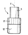
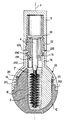
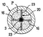
図1〜図4は、本発明に従って作製された包装型アプリケータ器具1を示している。
器具1は、第1の部品10及びこの例において器具1の長手方向軸線と一致した回転軸線X回りに第1部品に対して回転できる第2部品20を有している。
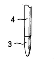
器具1は、アプリケータ2を更に有し、このアプリケータ2は、それ自体、図示の例ではブラシによって構成されたアプリケータ要素3を有している。
アプリケータ要素3は、ステム4により取っ手部材5に連結され、この取っ手部材5も又、容器のクロージャキャップを構成している。
図示の例では、ステム4は、回転軸線Xに沿って延びるが、これをどこか他の場所に設けてもよく、これは本発明の範囲から逸脱しない。
1-4 show a packaged
The
The
The
In the example shown, the
ステム4は、例えば、少なくとも一部が、プラスチック材料で作られるのがよく、ステム4は、少なくとも1つの材料、例えば、ポリアミド(PA)、ポリエチレン(PE)、ポリプロピレン(PP)、ポリスチレン(PS)、アクリロニトリル−ブタジエン−スチレンコポリマー(ABS)、スチレンアクリロニトリルコポリマー(SAN)、ポリアセチル(POM)又はポリエチレンテレフタレート(PET)から成るのがよいが、このリストには限定されない。
この例では、第1部品10は、例えば外側覆い12の内側に嵌め込むことができるポット11を有する。覆いは、ポット11の高さのほんの僅かな部分にわたって延びるのがよい。
The
In this example, the
一例を挙げると、覆い12を摩擦力、接着剤、ヒートシール又はスナップ留めによりポット11上に保持するのがよく、覆いは、例えば金属で作られ、ポット11は、熱可塑性材料で作られる。
覆い12を、適宜、エラストマー材料、例えば、熱可塑性エラストマーで作ってもよく、覆いの表面には、ユーザにとって持ちやすくする突起を設けるのがよい。
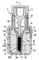
この例では、ポット11は、頂部凸部13及び環状密封リップ14を有している。
図4で理解できるように、ポット11は、物質Pを収容する内部空間15を構成する。内側空間15は、特に、最初の使用前に物質によって占められた空間に相当するのがよい。この場合、物質のレベル又は高さ位置は、容器の内部においてその最大状態にあり、容器の底部が外側フェースから測定してhiに達する。
As an example, the covering 12 may be held on the
The
In this example, the
As can be understood from FIG. 4, the
ポット11は、少なくとも1つのプラスチック材料、例えば、PE、PP、PA、POM、PS、ABS、SAN又はPETで作られたものであるのがよく(このリストには限定されない)、かかるポットは、アプリケータ要素3の付近まで内部空間15の中央に向かって半径方向に延び、実質的にこれと形状が相補する仕切り16を有する。
第2部品20は、凸部分13にスナップ留めするよう配置されていて、この例では、クロージャキャップ5を固定するのに適したねじ山付きネック22と一体に作られた外側スカート21を有している。
凸部分13は、例えば、第1部品10を第2部品に対して軸方向に保持し、これら部品を互いに対し回転できるようにするよう連続又は不連続の環状ビードの形態をしているのがよい。
The
The
The
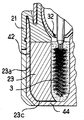
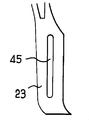
第2部品20は、この例では、スカート21及びネック22と一体に作られたブレード23を有する。図7に示す変形実施形態では、ブレード23は、第2部品20の残部に装着され、かくして、ブレード23をもし要望するならば異なる材料で作ることが容易になっている。
ブレード23は好ましくは、アプリケータ要素3とポット11の両方の形状に合う形状を備えている。
図3の例では、ブレード23は、物質を掻き取るようポット11の半径方向内面42の近くに位置することを可能にするプロフィールの半径方向外縁部23aを備えている。
The
The
In the example of FIG. 3, the
ブレード23の半径方向内縁部23bは、アプリケータ要素3の形状に実質的に合致した下方且つ内方に湾曲している底部分を有している。
ブレード23の底縁部23cは、容器の底壁44の形状に実質的に合致していて、これに付着存在する物質を掻き取るようになっている。
第2部品20は、少なくとも1つのプラスチック材料、例えば、PE、PP、PA、POM、PS、ABS、SAN又はPETで作られたものであるのがよいが、このリストには限定されない。
The radially
The
The
第1部品と第2部品との間の摩擦を減少させるためには第1部品と第2部品を作るのに互いに異なる材料を用いるのが有利な場合がある。
第2部品20が、図3に示すように第1部品10上の定位置にあるとき、環状密封リップ14は、組立体を密封するようスカート21の半径方向内面25に圧接する。他の密封手段を使用できる。
図3で理解できるように、器具1は、アプリケータ要素3が容器を出る際にアプリケータ要素3を拭い取るようネック22内に挿入されるのに適したワイパ部材30を有するのがよい。
In order to reduce the friction between the first part and the second part, it may be advantageous to use different materials to make the first part and the second part.
When the
As can be seen in FIG. 3, the
ワイパ部材30は、任意形式のものであってよく、例えば、その底端部のところに円形オリフィス32を構成する軟質リップ31を有するのがよく、オリフィスの直径は、実質的にステム4の直径に等しい。変形例では、オリフィス32は、他の或る直径のものであってよいと共に(或いは)円形ではない形状のものであってよい。
ワイパ部材30は、プラスチック材料、例えば、PE、PP、POM、PET、ニトリル、シリコーン、エチレンポリプロピレンジエン(EPDM)、スチレンイソプレン−スチレン(SIS)、又はスチレンエチレンポリプロピレンブダジエン−スチレン(SEBS)、例えば商品名Hytrel(登録商標)で知られている熱可塑性ポリエステルエラストマー、例えば商品名Santoprene(登録商標)で知られている熱可塑性エラストマーで作られたものであるのがよいが、このリストには限定されない。
The
The
ワイパ部材30をネック内に嵌め込む必要はなく、ワイパ部材をこれと一緒に成形してもよく、或いはネックをワイパ部材上に一体成形してもよい。
特に図4〜図6で理解できるように、ブレード23と仕切り16は一緒になって空間15内部に2つのチャンバ15a,15bを構成し、これらチャンバは、アプリケータ3が容器上の定位置に位置しているとき、アプリケータ要素3が位置する中央領域15cを介して互いに連通する。
ブレード23の各主要フェースは、回転面40を構成し、これら回転面のうちの1つは、第2部品20の回転方向に応じて、スラスト(推力)を物質に及ぼす。
It is not necessary to fit the
As can be seen in particular in FIGS. 4 to 6, the
Each main face of the
仕切り16は、受け面46を備えている。第1部品10に対する第2部品20の回転の終わりに、回転面40のうち1つは、実質的に受け面46のうちの1つと重なり合うようになる。
ユーザが第2部品20を第1部品10に対していずれかの方向に回すと、空間15内でのブレード23の運動により、チャンバ15a又は15bのうちの1つの容積が減少し、他方のチャンバの容積が増大し、それにより物質が一方のチャンバから中央領域15cを通って他方のチャンバに流れ、かくして、アプリケータ要素3に物質を充填することができる。
The
When the user turns the
図5の例では、チャンバ15bの容積が増大している間に減少しているのは、チャンバ15aの容積であり、したがって、物質は、チャンバ15aからチャンバ15b内へ流れ、これに対し、図6はこれと逆の状況を示している。
例えば、ユーザが片手で覆い12を保持し、もう片方の手で外側スカート21を回して第2部品20を第1部品10に対して回すと、内部空間15内でのブレード23の運動により、物質Pが或る程度攪拌され、これは物質を一様にするのに寄与することができる。
In the example of FIG. 5, it is the volume of
For example, when the user holds the
図示の例では、第1部品と第2部品を互いに組み付けたときにこれらにより形成される容器の高さを容器の最大横方向寸法dで割った比he/dは、0.1〜10、例えば0.1〜2であるのがよく、特に、d>he/2の場合に可能であり、これは、マスカラを包装すると共に塗布する従来型の器具の非常に細長い外観とは非常に異なる比較的ずんぐりとした外形を器具に与えることができる。
容器の内部空間15の高さhiと容器の最大横方向寸法dの比hi/dは、例えば0.1〜10であるのがよく、特に、d>hiの場合に可能である。
In the illustrated example, the maximum transverse dimension divided by the ratio in d h e / d of the container a height of the container formed by these when assembling the first and second parts to each other, 0.1 to 10 may that for example from 0.1 to 2, in particular, is possible in the case of d> h e / 2, which is quite the very slender appearance of a conventional device for applying with the packaging of mascara The instrument can be given a relatively stubby profile.
The ratio h i / d of the largest transverse dimension d of the height h i and the container
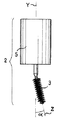
アプリケータのステム4は、図8に示すように細い部分4aを備えるのがよい。細い部分4aは、ワイパ部材のオリフィス32と符合する位置を取ることができ、この場合、オリフィス32の直径は好ましくは、その細い部分4a以外のステム4の直径に実質的に等しい。細い部分4aが設けられていることにより、アプリケータが容器上の定位置にあるとき、ステム4によりワイパ部材に及ぼされる応力が減少する。適宜、そして図9に示すように、アプリケータ要素3は、アプリケータの長手方向軸線Yと、ゼロではない角度αをなす長手方向軸線Zに沿って延びるのがよい。
図1の実施形態では、物質を収容する内部空間は、側部がポット11によってのみ構成される。
図10及び図11に示す変形例では、物質を収容する内部空間は、側部がポット11により底部寄りに且つ第2部品20の外側スカート21により頂部寄りに構成される。
The
In the embodiment of FIG. 1, the internal space for containing the substance is constituted only by the
In the modification shown in FIGS. 10 and 11, the internal space for accommodating the substance is configured such that the side portion is close to the bottom portion by the
アプリケータのステム4は、図12及び図13に示すように入れ子式であるのがよい。
ステム4は、第2の部分、例えば頂側部分4c内に嵌まり込み、頂側部分内でアプリケータの長手方向軸線Yに平行に摺動できる第1の部分、例えば底側部分4bを有するのがよい。底側部分4bは、他方の部分4c内でのその移動行程を制限できる凸状一端部を備えるのがよい。
アプリケータ2が容器内の定位置にあるとき、ステム4は、図12に示すように、その引っ込み位置にある。
The
The
When the
ユーザがアプリケータ要素3を容器から取り出そうとすると、アプリケータ要素3は、ワイパ部材30に当接することができ、かくして、ステム4を展開してこれを図13に示す形態にすることができる。
ステム4をいったん展開すると、ユーザは、アプリケータ要素3をワイパ部材30中に通すことができる。
アプリケータ要素3を容器内に戻すと、ステム4は、引っ込みを開始することができ、その後、アプリケータ要素3がワイパ部材を通過する。
入れ子式ステムを用いると、これを当然のことながら、図1に示す容器以外の容器に関連させることができる。
適宜、そして図14〜図16に示すように、物質がブレードの運動中、ブレードを通過できるようにするか開口部部45をブレード23に形成するのがよい。
When the user tries to remove the
Once the
When the
With the use of a telescoping stem, this can, of course, be associated with containers other than those shown in FIG.
Optionally, and as shown in FIGS. 14-16,
ブレード23は、多数の開口部45、例えば、図14に示すような円形の開口部、又は図15に示すような水平スロットの形態をした開口部、若しくは例えば図16に示すような単一の垂直スロットの形態をしているのがよい単一の開口部45を有するのがよい。
開口部45により物質に利用できる貫通断面は好ましくは、ブレード23を動かすと、所要量の物質が中央領域15cを通って流れるようにするほど小さい。
適宜、ブレード23は、捩れたものであるのがよく、例えば、ブレードが物質中を通って動く方向に対し下方且つ前方に曲げられた底部を備える。
ブレード23は、図14に示すように回転軸線Xに垂直な軸線W回りに曲げられた部分23eを有するのがよく、それにより、ブレードが動いている間、物質を持ち上げ、かくして、物質が重力の作用下で容器の底部に堆積するのをしにくくする。
The
The through section available for material by opening 45 is preferably small enough to allow the required amount of material to flow through
Optionally, the
The
ブレードを曲げないで、ブレードの底部を厚くして物質に圧接する表面40が物質を持ち上げようとするようにすることも可能である。
当然のことながら、捩れたブレードには開口部45を設けないのがよい。本発明は、特定のアプリケータ要素3には限定されず、一例を挙げると、図17は、アプリケータ要素3がフロック加工されたエンドピースである変形実施形態を示している。
図17は又、外側覆い12を用いないで第1部品10をプラスチック材料の一体成形品として作る可能性を示している。
図17では、ブレード23を異なる形状にできることが示されており、特に、その底部は、L字形であるのがよく、ブレード23は、例えば軸線Xまで実質的にアプリケータ要素3の下を延びる。
Without bending the blade, it is possible to thicken the bottom of the blade so that the
Of course, the twisted blade should not be provided with the
FIG. 17 also shows the possibility of making the
FIG. 17 shows that the
これと同様に、仕切り16の底部は、軸線Xまで実質的に内部に向かって延びるL字形のものであるのがよい。
第1部品及び第2部品を多くの他のやり方で組織化することができ、これは本発明の範囲から逸脱しない。
一例を挙げると、図18は、底部44の周囲の下方延長部として、例えば鏡又は製品サンプル(図示せず)を収容するのに適したハウジング51を構成するリブ50が設けられた変形実施形態を示している。
この例では、第2部品の外側スカート21は、少なくとも1つの凹凸部分、例えば、ポット11の底部に形成された溝54内に対応関係をなして嵌まり込むように形作られた環状ビード52を備えている。
Similarly, the bottom of the
The first part and the second part can be organized in many other ways without departing from the scope of the present invention.
As an example, FIG. 18 shows an alternative embodiment in which a
In this example, the
図18は又、ブレード23が第1の凹凸部分、例えば、第2の凹凸部分、例えば第1部品10に設けられた凹み57と協働するスタッド56を備えてもよいことを示している。凹み57は、第2部品20が回転している間、ブレード23の底部に或る程度の案内作用を持たせるよう軸線Xに関して円対称であるのがよい。
図19に示す変形例では、スタッド56は、底壁44と一体に形成され、凹み57は、第2部品に一体に形成される。
適宜、第1及び第2部品のうち少なくとも一方は、アプリケータ2が容器上の定位置にあるとき、アプリケータ要素3を収納位置決めするチムニ(煙突状部分)を備えるのがよい。
FIG. 18 also shows that the
In the modification shown in FIG. 19, the
Suitably, at least one of the first and second parts may comprise a chimney (chimney-like part) that houses and positions the
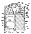
図20では、第2部品20は、ポット11の内部空間15の中央領域15c内に嵌まり込むチムニ60を備え、このチムニ60には複数の開口部61が穴あけされており、これら開口部により、チャンバ15a又は15bのうちの一方から反対側のチャンバに向かって流れる物質がこれら開口部を通ってチャンバ内に位置しているアプリケータ要素3を満たすことができる。
ポット11の底壁44は、適宜、チムニ60の底壁に形成された第2の凹凸部分65、例えば凹みと協働するよう配置された第1の凹凸部分63、例えばスタッドを備えるのがよい。
In FIG. 20, the
The
図21の例では、上述のチムニ60と同様、例えば軸線Xに平行な細長いスロットの形態をした開口部71を有するチムニ70を備えているのは、第1部品10である。
アプリケータ2が容器上の定位置にある間、アプリケータ要素3をチムニ70内に収納することができる。
第2部品20をプラスチック材料の成形により単一部品として作るのがよく、或いは、変形例として、別々に作られ、後で互いに組み付けられる少なくとも2つの部品を組み合わせることにより作ってもよい。
In the example of FIG. 21, it is the
The
The
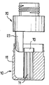
図22の例では、第2部品20は、第2部品20が軸線X回りに回転するのを可能にしながら第2部品20を軸方向に保持するよう第1部品10と協働する外側部分75及び外側部分75と一緒に回転する内側部分76を有する。外側部分75を種々のやり方で内側部分76に組み付けることができる。
外側部分75は、例えば、ネック22を含むのがよく、内側部分76は、ネック22内に嵌まり込むインサート78を含むのがよく、インサート78は、例えば、ワイパ部材79と一体に作られる。内側76は、例えば、ブレード23を支持し、ポット11の半径方向内側の表面に当接する環状密封リップ82を周囲に備えたプレート80を更に含むのがよい。
In the example of FIG. 22, the
The
図23に示す変形実施形態では、第2部品20は同様に、外側部分75及び内側部分76を有する。この例では、第2部品20を第1部品10上に軸方向に保持するために、第1部品10と共同するのは内側部分76である。内側部分76は、例えば、第2部品が軸線X回りに回転するのを可能にしながら、第2部品20を軸方向に保持するようポット11の外側ビード85を嵌入させる内側溝84を備えた外側スカート83を意味する。内側部分76は、ポット11の半径方向内側の表面に圧接する環状密封リップ82を更に有する。外側部分75は、例えば摩擦により内側部分76と組み立てられる。ワイパ部材30は、外側部分75と一緒に形成できるネック22内に嵌め込まれ、これは、外側部分75と一緒に形成されたチムニ86内に漏れ止め状態で嵌まり込む。
In the variant embodiment shown in FIG. 23, the
上述の実施形態では、第1部品10は、少なくとも1つの受け面46を備えた仕切り16を有する。第1部品10が、図24及び図25に示すようにかかる仕切りを備えないことは本発明の範囲から逸脱しない。この変形実施形態では、第2部品20は、2つの回転面40を備えたブレード23を有し、これら回転面のうち少なくとも一方は、上記ブレード23を適当な方向に、例えば、図25に示す例では半時計回りの方向に回すと、物質を中央に向かって逸らすような仕方で湾曲した形状を備える。
図24及び図25の例では、内部空間15は、チャンバを1つしか備えていない。物質Pは、第2部品20が上記チャンバに対して回転すると、上記チャンバ内で動く。
In the embodiment described above, the
In the example of FIGS. 24 and 25, the
図24では、ブラシ以外の形態、例えば、プラスチック材料を射出成形することにより作られた櫛の形態でアプリケータを作る可能性があることも分かる。
上述の実施形態では、アプリケータは、回転軸線Xに実質的に平行な方向で容器から取り出される。
アプリケータを軸線Xに対して平行ではない方向、特に、図26〜図28に示す実施形態に適用される軸線Xに垂直な方向Yに取り出すことは本発明の範囲から逸脱しない。
In FIG. 24 it can also be seen that applicators may be made in forms other than brushes, for example in the form of combs made by injection molding plastic material.
In the embodiment described above, the applicator is removed from the container in a direction substantially parallel to the axis of rotation X.
Taking the applicator in a direction that is not parallel to the axis X, in particular in a direction Y perpendicular to the axis X applied to the embodiment shown in FIGS. 26-28, does not depart from the scope of the present invention.
この例では、器具1は、第1部品10の側部から軸線Xに実質的に垂直に延びるネック22を備えた第1部品10を有する。第1部品10のポット11は、第2部品20によって閉鎖されている。一例を挙げると、仕切り16は、材料の成形によりポット11と一体に作られる。第2部品20は、外側フェース上に鏡90を支持し、更に、回転軸線Xに実質的に平行に延びるブレード23を支持するのがよい。
クロージャキャップ5は、ユーザが鏡90を利用しようとすると、器具1の取っ手を形成するよう細長い形状のものであるのがよい。この例は、アプリケータ要素をブラシ以外の要素、具体的に言えば、例えばテーパした先端部を持つエンドピースによって構成できることを示している。
In this example, the
The
図29では、アプリケータの長手方向軸線Yとゼロではない角度αをなす長手方向軸線Zを有するようアプリケータのアプリケータ要素3を作る可能性のあることが理解できる。
図30は、第1及び第2部品の各々が、実質的に半球形の部分を備えている変形実施形態を示している。この図において理解できることとして、ブレード23の半径方向内側縁部23bが、アプリケータ要素のプロフィールに実質的に一致するのがよい。この実施形態では、容器の底部は、平らではない。
図面を参照して上述した実施形態では、アプリケータ2は、利用中、器具から取り出され、ステム4の端部に取り付けられるアプリケータ要素3を有する。これらの例では、アプリケータ要素3は、クロージャキャップ5が容器上の定位置にあるときはいつでも、物質の入った容器の内部に収納される。
In FIG. 29, it can be seen that the
FIG. 30 shows an alternative embodiment in which each of the first and second parts comprises a substantially hemispherical portion. As can be seen in this figure, the radially
In the embodiment described above with reference to the drawings, the
アプリケータ要素3を器具に永続的に固定すること及び(又は)使用していない間、物質を収容した空間内に収容しないようにすることは、本発明の範囲から逸脱しない。
一例を挙げると、図31及び図32は、この例では、第1部品110及び器具の回転軸線と一致した回転軸線R回りに第1部品110に対して回転できる第2部品120を有する器具100を示している。
器具100は、アプリケータ102を更に有し、アプリケータ102は、この例では、例えばフォームから成るアプリケータ要素103を有し、上記アプリケータ要素103は、取っ手としても役立つクロージャキャップ105の内側スカート150によって支持されている。
Permanently securing the
To give an example, FIGS. 31 and 32 show, in this example, an
The
キャップ105は、ネック122の内壁に圧接する環状密封リップ151を有し、このネックは、例えば外側ねじ山を有し、第2部品120に一体に作られている。
この例では、第1部品110は、図32で理解できるように、内側空間115を構成するポット111を有し、物質は、このポット内に入れられる。
ポット111は、軸線Xの近くに且つこれが環状密封リップ114を備えた頂部の近くに位置するよう内部空間115の中央に向かって半径方向に延びる仕切り116を有し、この環状密封リップ114は、外部に、第2部品120を保持するのに役立つ凹凸部分113を備えている。一例を挙げると、凹凸部分113は、環状ビードである。
The
In this example, the
The
第2部品120は、凹凸部分113にスナップ留めされるよう配置され、この例ではネック122と一体に形成された外側スカート121を有する。
ブレード123も又、この例では、外側スカート121及びネック122と一体に作られている。
ブレード123の半径方向内側縁部123bは、好ましくは仕切り116の半径方向内側縁部から僅かな距離のところで内部空間115の中央領域115c内に位置している。
The
The
The radially
この例では、ポット111の底壁144は、例えば凹み124によって構成された第1凹凸部分を有し、この第1凹凸部分は、例えばブレード123を回転時に案内するようブレード123の底部123c上に形成されたスタッドにより構成された第2凹凸部分と協働するよう配置されている。
ブレード123の半径方向外側縁部123aは、ほぼポット111の内壁142まで延びて上記壁142上に堆積するようになった物質を掻き落とすようになっている。
図31及び図32の器具の作用は以下の通りである。
ブレード123は、2つの互いに反対側の回転面140を備え、仕切り116は、2つの関連した受け面146を備える。
In this example, the
The radially outer edge 123a of the
The operation of the device of FIGS. 31 and 32 is as follows.
The
仕切り116は、2つのチャンバ115a,115bを構成するようブレード123と協働する。第2部品120を第1部品110に対して回すと、ブレード123が動き、その運動に伴って、チャンバ115a又は115bのうちの一方のうちの容積が減少し、物質は、その容積部から出てアプリケータ要素103に向かって移動する。
図34は、篩又はグリッドから成り、少なくとも1つの開口部181、より良好には、複数の開口部181を備えた透過性の壁180をアプリケータ要素103と内部空間115との間に介在させる可能性を示している。
The
FIG. 34 consists of a sieve or a grid and interposes between the
図33の例では、アプリケータ102は、クロージャキャップ105には固定されず、第2部品120に固定されている。
図示の例では、アプリケータ要素103は、例えば、第2部品120を回すと、物質Pを受け入れるよう配置されている内面191を備えた凹部分190を有するフォームから成る。
クロージャキャップ105は、アプリケータ要素103の周りに延びる第2部品120の壁192と協働する環状密封リップ151を有するのがよい。
In the example of FIG. 33, the
In the illustrated example, the
The
図33は又、キャップ105が種々の形状のものであってよいこと、例えば、アプリケータ要素103の形状に一致した形状の頂壁を示している。
図33の例では、ブレード123は、例えばスタッドにより構成された凹凸部分125を備え、この凹凸部分125は、例えばポット111の底壁144に設けられた凹みにより構成される第2凹凸部分124と協働する。
この底壁の周囲の下方延長部として、例えば鏡又は製品サンプル(図示せず)を収容するのに適したハウジング151を構成するスカート150が設けられている。図示の例では、底壁144は、ハウジング151に設けられていて、凹み124を形成できる膨らみ部を備えている。
FIG. 33 also shows that the
In the example of FIG. 33, the
As a downward extension around this bottom wall, for example, a
図31を参照して説明した仕方と同一の仕方で物質Pは、ポット111の2つのチャンバ115a,115b内の内部空間155に収容され、これらチャンバは、ブレード123及び仕切り116によって構成されている。
物質Pは、ブレード123をユーザがいずれかの方向に回転させると、アプリケータ要素に向かって追い出される。ポット111から来る物質Pを凹部分190に向かって運搬するためにダクト193を第2部品120と一体に形成するのがよい。物質Pがアプリケータ要素103の内面191に接触することにより、物質Pはアプリケータ要素に供給される。
The substance P is accommodated in the internal space 155 in the two
The substance P is expelled towards the applicator element when the user rotates the
図35では、アプリケータ要素103は、物質をリップに塗布するようになっており、このアプリケータ要素は、回転軸線Xに対し傾斜した頂部フェース103aを備えている。この頂部フェース103aにアプリケータ要素103を通るチャネル103bを介して物質を供給することができる。クロージャキャップ105がキャップのペグ105aによって定位置にある間、チャネル103bを閉鎖するのがよい。
当然のことながら、本発明は上述の実施形態には限定されない。
特に、第1部品10又は第2部品20のクロージャキャップの外側の形状を変えることができ、これは本発明の範囲から逸脱しない。
一例を挙げると、図37〜図49は、とりわけキャップ5、第1部品10及び第2部品20について考えられる形状の種々の例を示している。
考えられる形状は、例えば長手方向軸線Y又は任意の横方向軸線に沿って様々であってよい。
In FIG. 35, the
Of course, the present invention is not limited to the embodiments described above.
In particular, the outer shape of the closure cap of the
As an example, FIGS. 37 to 49 show various examples of possible shapes for the
Possible shapes may vary, for example, along the longitudinal axis Y or any lateral axis.
図37〜図49に示す形状は、図31〜図36の実施形態にそのまま適用でき、参照符号5、10及び20に代えてそれぞれ参照符号105、110及び120が用いられている。
図37の例では、第2部品20の外側スカートは、第1部品10から半径方向外方に突き出ている。
図38の例では、第2部品20に対し半径方向外方に突き出ているのは、第1部品10である。
図39の実施形態の例では、器具の全体形状は、ペンのように明らかに細長い。
図40は、クロージャキャップ5がこれを掴みやすくするよう外方に凹状の形状を備えるのがよいことを示している。
図41では、クロージャキャップ5は、切頭弾丸の形状をしており、第1部品10は、形状が切頭円錐形であり、その外側断面は、下方にテーパしている。
図42では、第1部品10及び第2部品20は、丸くなった縁部を有している。
図43では、クロージャキャップ5の高さは、第1部品10と第2部品20を互いに組み付けたときのこれらの高さよりも大きい。
The shapes shown in FIGS. 37 to 49 can be applied as they are to the embodiments of FIGS. 31 to 36, and
In the example of FIG. 37, the outer skirt of the
In the example of FIG. 38, the
In the example embodiment of FIG. 39, the overall shape of the instrument is clearly elongated like a pen.
FIG. 40 shows that the
In FIG. 41, the
In FIG. 42, the
In FIG. 43, the height of the
第1部品10は、2重壁を有するのがよく、外壁99及び内壁11は、例えば、互いに異なる底部断面を有している。
例えば、外壁99は、図44に示すように実質的に正方形又は矩形の断面を有するのがよく、或いは、他の或る形状、例えば、図45に示すようにレンズ形であってもよい。
第2部品20も又、外壁410を含む外壁2重壁を有するのがよく、壁99,410の輪郭は、図77に示すように、第2部品に対する第1部品の或る特定の角度位置でのみ互いに一致するのがよい。
第2部品20は、図46及び図47に示すように、例えばエラストマーで作られた外側覆い95を有するのがよい。
The
For example, the
The
As shown in FIGS. 46 and 47, the
図46では、外側覆い95は、例えば摩擦によりこの図では見えない外側スカート21と協働するスリーブの形態をしている。一例を挙げると、スリーブは、その周囲全体にわたり外方に凹状の軸方向断面を有するのがよい。
図47では、外側覆い95は、同様にスリーブの形態をしており、このスリーブは、形状が全体として外方に凸状であるのがよい。
第2部品20の外側スカート21に凹凸部分、例えば図48に示すようなフィン96を形成するのがよい。
また、第1部品及び第2部品のうち一方及び(又は)他方を図49に示すように2重壁97で被覆することも可能であり、かくして、ボリュームのある印象が与えられる。
In FIG. 46, the
In FIG. 47, the
An uneven portion, for example, a
It is also possible to cover one and / or the other of the first part and the second part with a
第1及び(又は)第2部品の断面は、軸線Yに沿う少なくとも1つの箇所で種々の形状を備えてもよく、例えば、これは、図50に示すように全体として円形であり、図51に示すように場合によっては丸いコーナ部を持つ実質的に正方形であり、図52に示すように例えば丸いコーナ部を持つ実質的に矩形であり、或いは図53に示すように実質的に楕円形であってよい。
単一の器具内では、第1及び(又は)第2部品の断面は、長手方向軸線Xに沿って様々であってよい。
一例を挙げると、図54は、断面形状が、その底端部のところでの楕円形から第1部品10と第2部品20との間の接合部のところで円形に移り、そしてその後クロージャキャップ5の下で容器の頂部に向かって楕円形に戻る器具を示している。
The cross section of the first and / or second part may comprise various shapes at at least one location along the axis Y, for example, it is generally circular as shown in FIG. In some cases, it is substantially square with rounded corners, for example, substantially rectangular with rounded corners as shown in FIG. 52, or substantially elliptical as shown in FIG. It may be.
Within a single instrument, the cross-section of the first and / or second part may vary along the longitudinal axis X.
As an example, FIG. 54 shows that the cross-sectional shape has shifted from an ellipse at its bottom end to a circle at the junction between the
第1部品と第2部品との間の円形接合部を有する状態で容器の断面形状が上記のように変化することにより、密封性を損なわないで元の形状の容器を提供することができ、しかも第1及び第2部品のうち一方を他方に対して回すために第1及び第2部品を掴むのを容易にすることができる。
図55では、第1部品10は、全体として円形の断面を有し、第2部品20の底端部ところの断面が、キャップ5の下の容器の頂部のところの実質的に正方形である形状に向かって変化している。
容器の形状がどのようなものであれ、クロージャキャップ5は、容器を第1及び第2部品のうち一方に対して実質的に静止状態に保持できるようにする係止システムを有するのがよい。係止システムが設けられているので、キャップ5は、第1部品10が第2部品20に対して回転しても、ねじ戻って弛むことはない。これにより、ユーザが部品のうち一方を回すのが容易になる。
By changing the cross-sectional shape of the container as described above in a state having a circular joint between the first part and the second part, it is possible to provide a container of the original shape without impairing the sealing performance, Moreover, it is possible to easily grasp the first and second parts in order to turn one of the first and second parts relative to the other.
In FIG. 55, the
Whatever the shape of the container, the
一例を挙げると、図80に示すように、係止システムは、クロージャキャップ5を十分にねじ回すと、第1及び第2部品のうち一方に形成されたラチェットにスナップ動作で当たる爪421を有するのがよい。
クロージャキャップ5をねじ戻して弛めるためには、爪は、ラチェット420から逆方向に逃げなければならない。爪が逆方向に逃げることができるようにするために及ぼさなければならない力は、部品のうち一方を他方に対して回すのに必要な力よりも大きいのがよい。かくして、ユーザは、第1部品が所望の結果に応じて、一方向にのみ又は複数の前後方向に第2部品に対して回転するようにするための取っ手としてクロージャキャップを利用することができる。しかる後、塗布に取り掛かるために、ユーザは、2つの部品10,20を互いに対し静止状態に保持しながらキャップを強く回すと、爪をラチェットから外すことができる。爪をラチェットから外すのを可能にすると共に(或いは)容易にするために、或る追加の作用をキャップに与える必要のある場合があり、例えば、ラチェット及びクロージャキャップの形態に応じて、力をキャップに軸方向に及ぼす場合がある。
As an example, as shown in FIG. 80, the locking system includes a
In order to unscrew and close the
図56及び図57に示す変形例では、係止システムは、クロージャキャップに設けられ、或いは、変形例(図示せず)では、第1及び第2部品の一方に設けられ、任意的にクロージャキャップを第1及び第2部品のうち一方と一緒に回転させないようにするのに役立つ押しボタン220を有する。
ユーザが押しボタン220を押して第2部品20を第1部品10に対して回すと、クロージャキャップ5は、部品のうち一方に固定されたままであって、ねじ戻って弛むことはない。
図58及び図59は、容器が外部に幅の広い長手方向リブを備えた本発明の器具の別の実施形態を示している。
第2部品20は、雄ねじ付きのネック22を備えた外側部分75を有し、クロージャキャップ5をこの雄ねじに螺着させることができる。
ネック22の底部は、肩225に連結されている。
56 and 57, the locking system is provided on the closure cap, or in the alternative (not shown), on one of the first and second parts, optionally the closure cap. Has a
When the user pushes the
58 and 59 show another embodiment of the device of the present invention wherein the container is provided with a wide longitudinal rib on the outside.
The
The bottom of the
ワイパ部材30は、ネックの頂縁部上に載り、このワイパ部材は、肩225の下面に当接する環状保持リップ230を備えている。
ワイパ部材30は、内方に延びるワイパリップ231を有し、図示の例では、器具が閉鎖位置にあるとき、このワイパ部材は、アプリケータ2のステム4に当接する。
外側部分75は、クロージャキャップ5と整列した状態で肩225の下に下方に延びる全体として円筒形の部分232を有している。
この円筒形部分232の内側にはリブ(溝)を設けて内側部分76を例えば円筒形部分232のクランプ作用により外側部分75内で動かないようしっかりと固定状態に保ちやすくするのがよい。
内側部分76は、この例ではブレード23を支持している。
全体として円筒形の部分232の底部は、全体として半球形の部分311に連結され、それにより、第2部品10の密封リップ14が当接できる円筒形の表面310が形成されている。
The
The
The
It is preferable to provide a rib (groove) on the inner side of the
The
The bottom of the generally
図示のように、部分311は、第1部品10がスナップ動作で嵌まり込むことができる内部傾斜溝312を有するのがよい。
第1部品10は、例えばプラスチック材料を成形することにより図示の例では単一部品として作られている。
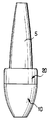
一例を挙げると、アプリケータ要素3は、マスカラブラシであるが、任意他の形式のアプリケータ要素であってよく、これは本発明の範囲から逸脱しない。
一例を挙げると、アプリケータ要素3は、図60に示すように、ロッドの直径よりも小さな最大横方向寸法を備えたエンドピースであるのがよい。
As shown, the
The
By way of example, the
As an example, the
図61に示すように、ワイパ部材30は、ネック22と一体に作られ、その拭い取り機能を実行するためにリップの内部に延びるワイパリップを有するのがよい。
図62の実施形態では、器具は、図59の器具とほぼ同じ外形を有するが、他の或る形状のものであってよい。
図62の器具は、液体であり、又は、他の或る稠度を有する物質を塗布するためのもの、例えば、リップスティックであり、アプリケータ要素3は、第2部品20に永続的に固定される。
一例を挙げると、アプリケータ要素3は、ネックの頂端部に固定されたフロック加工グリッド241を有し、このネックは、外側ビード240を有するのがよく、これと対応したクロージャキャップ5の環状溝がこのビードにスナップ式に嵌合する。
グリッド241は好ましくは、物質を例えば唇に塗布しやすくするために角度をなして設けられる。
As shown in FIG. 61, the
In the embodiment of FIG. 62, the instrument has approximately the same profile as the instrument of FIG. 59, but may be of some other shape.
The device of FIG. 62 is a liquid or for applying a substance with some other consistency, for example a lipstick, the
As an example, the
The
第1部品10を第2部品20に対して回すと、物質がチムニ245を経てアプリケータ要素3に向かって進められ、物質は、図64で明確に分かる環状溝246を通って外部に移動する。
グリッド241は、多種多様な形状のものであってよく、図65に示すようにグリッド全体又は一部をフロック加工するのがよいが、このようにするかどうかは任意である。
アプリケータ要素3は、図66に示すように、1以上のオリフィス320を備えたエラストマー、例えば熱可塑性エラストマーから成るのがよい。
As the
The
The
図67に示す器具は、頂部がアプリケータ要素3と連通した浸漬管340を有し、この浸漬管は、ボールを有するが、これに代えて、任意他の小出し手段、例えば任意的にフロック加工されたエンドピース、フォーム、フェルト等を用いてもよい。
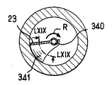
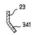
一例を挙げると、第2部品20は、矢印で示されるようにブレード23の回転方向が所与である場合、下方、内方及び後方に同時に湾曲した底側部分341を備えたブレード23を有し、したがって、ブレード23を回すと、物質は、浸漬管340の底部が開口している中央領域344に向かって追い出されるようになる。
部品が所定の方向Rに互いに対して回るようにするために、爪351を備えた弾性変形可能なタブ350を第2部品20に設けるのがよく、例えば、爪351は、逆方向の回転を阻止するような仕方で構成されたラチェット352に圧接する。
The instrument shown in FIG. 67 has a
As an example, the
In order to allow the parts to rotate relative to each other in a predetermined direction R, the
この例では、ラチェット352は、第2部品の環状溝312内に延びるように作られている。
図71に示すように、上述したような適当な器具を、少なくとも1つの追加の成分、例えば溶剤が入っていて、器具内部に入っている物質を用いる時点で追加される管250又は他の容器と組み合わせてキット300の状態にすることができる。
第1部品10を第2部品20に対して回すことにより、物質をこのようにして挿入される成分と混合し、混合物を一様にすることができる。
これにより、例えば、器具の充填時に、熱い状態のままで注入された油をリップスティックに追加することができる。
In this example, the
As shown in FIG. 71, a suitable instrument as described above is added to a
By turning the
This makes it possible to add oil injected in a hot state to the lipstick, for example when filling the instrument.
ブレード23及び(又は)仕切り16が他の或る形状のものであることは本発明の範囲から逸脱しない。特に、ブレード23及び(又は)仕切り16の厚さは、互いに異なっていてもよい。例えば、ブレード23及び(又は)仕切り16は、全体として3角形、矩形又は他の形状の断面を有してもよい。
アプリケータ要素が他の或る形状を有することは本発明の範囲から逸脱せず、例えば、これは、塗料ばけ、櫛の形態又は他の或る形態をしていてもよい。
一例を挙げると、図72〜図76は、アプリケータ要素の他の例を示している。
例えば、アプリケータ要素は、図72及び図73の例に示すように中空であってよい。
It is within the scope of the invention for the
It does not depart from the scope of the present invention that the applicator element has some other shape, for example, it may be in the form of a paint brush, a comb or some other form.
To give an example, FIGS. 72-76 show other examples of applicator elements.
For example, the applicator element may be hollow as shown in the example of FIGS. 72 and 73.
図72は、睫毛又は眉毛用の櫛を示しており、この櫛は、例えば、相互に係合し、ベースがフレーム402に連結された2つの一連の歯400,401から成る。
図72のアプリケータ要素3は、例えば、米国特許出願第2002/0005209号明細書に従って作られ、かかる米国特許出願明細書の内容を参照によりここに引用する。
図73では、アプリケータ要素3は、中央空所403を有する。この空所は、容器の第1及び第2部品を互いに対して回すと、物質で満たされるようになることができる。
図74及び図75では、形状が全体的に平らであり、例えばステム4の直径よりも小さな厚さtを備えたアプリケータ要素3が図示されており、したがって、物質は、アプリケータ要素3を引き抜いてワイパ部材中に通した後、アプリケータ要素3の主要フェースの各々に付着存在したままであることができる。
FIG. 72 shows a comb for eyelashes or eyebrows, which consists of, for example, two series of
The
In FIG. 73, the
In FIGS. 74 and 75, an
図76に示すアプリケータ要素3は、貫通空所を備えておらず、その主要フェースのうちの一方に少なくとも1つの空所406を有し、具体的には、このアプリケータ要素は、2つの互いに反対側の空所406を有する。アプリケータ要素3は、例えばステム4の直径に実質的に一致した最大横方向寸法の拡大遠位端部407を有する。物質は、たとえアプリケータ要素3がステム4の直径に実質的に一致した直径のワイパ部材を通過するときでも、空所406の各々の中に堆積することができる。
部品10,20のうち一方は、図78に示すように、複数のブレード23、例えば2つの直径方向反対側のブレード23を有し、他方の部品は、複数の仕切り16、例えば2つの直径方向反対側の仕切り16を有するのがよい。ブレード及び仕切りの形状は、任意であってよく、例えば、これらは、1以上の開口部を有し、平らであってもよく、或いは他の状態であってよい。
The
As shown in FIG. 78, one of the
図79は、特に、唇又は皮膚への塗布のためのエンドピースで構成され、任意的にフロック加工部413で覆われたアプリケータ要素3を有する点において図59に示す器具とは異なった器具を示している。
隙間414が、アプリケータ要素3の周りに設けられていて、部品を互いに対して回した後、物質の膜が、アプリケータ要素3の周りに残るようになっており、この物質の膜は、比較的厚いものであるのがよい。
ネックは、ワイパリップ415を有するのがよい。このリップは、ブレード23と一体に作られるのがよく、或いは、変形例では、別個の装着部品によって構成されたものであってよい。器具は、使用前に互いに混合することが必要な複数の相の物質を収容してもよい。
また、ワイパリップ415を省いてもよい。
FIG. 79 differs from the device shown in FIG. 59 in that it comprises an
A
The neck may have a
Further, the
図81は、器具が出口オリフィス426を備えた内部空間425を有することが可能であることを示しており、この出口オリフィス426は、回転軸線Yに対しオフセンタ状態にある。このオリフィス426は、アプリケータ要素3に物質を供給するために内部空所427中へ開口するのがよく、このアプリケータ要素は、例えば、物質に対し透過性の材料で作られた壁を有するのがよい。
内部空間425は、例えば、第2部品20を第1部品10に対して回すことにより利用時に一様な混合物の状態に配合することが必要な複数の相P1,P2を収容することができる。
器具を充填している間に、周知の相を連続的に流し込むことができる。
FIG. 81 shows that the instrument can have an
The
While filling the device, a known phase can be poured continuously.
図81の器具は、例えば少なくとも1つのブレード23及びバッキングブレード(図示せず)を有するのがよく、或いは、回転時に、器具の内容物を一様にするのに役立ち、そして適宜、内容物がオリフィス426を通過するのを助けるのに役立ち又は内容物をオリフィス中に押し込むブレードを1つだけ有してもよい。
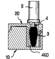
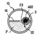
図82〜図84は、本発明の別の実施形態を構成する器具を示している。
この器具では、アプリケータは、回転軸線Yに対しオフセンタ状態にある。アプリケータは、アプリケータ要素3、例えば、図示の例の場合のようにブラシを有し、このアプリケータ要素は、オフセンタハウジング450内に受け入れられる。
一例を挙げると、ハウジングは、第2部品20によって駆動されるブレード23が器具内で回ると、物質Pを挿通させることができるように有孔壁451を有するのがよい。
The instrument of FIG. 81 may have, for example, at least one
82-84 show an instrument that constitutes another embodiment of the present invention.
In this instrument, the applicator is off-center with respect to the rotational axis Y. The applicator has an
As an example, the housing may have a
一例を挙げると、壁451は、一連の長手方向スロット453を有するのがよい。
ハウジング450は又、別形態に作ることができ、壁451は、別態様の孔を有してもよい。図85に示す変形例では、アプリケータ要素3を受け入れるハウジング460は、ブレード23と一体に作られ、このハウジングは、第1部品10に対しブレード23と一緒に回転する。
所望ならば、器具のうち任意のものに関し、弾性変形可能な多孔質材料、例えば図87に示すような連続気泡フォームのブロックを用いてワイパ部材を作ってもよい。
本発明の種々の実施形態の特性を互いに組み合わせて図示していない変形例を構成することができる。
[1] 物質(P)を包装すると共に塗布する器具(1)であって、物質(P)を収容する容器(10,20;110,120)を有し、容器は、第1の部品(10;110)及び第2の部品(20;120)から成り、第2部品(20;120)は、ユーザにより第1部品(10;110)に対して回転可能であり、前記器具は、アプリケータ(2;102)を更に有し、第2部品(20;120)は、容器内部の物質と接触状態にある少なくとも1つの表面(40;140)を備え、アプリケータ(2;102)及び前記表面(40;140)は、前記表面(40;140)を回転させると、圧力が物質(P)に及ぼされて物質がアプリケータ(2;102)に向かって移動するような態様で配置され、第1部品(10;110)は、受け面(46;146)を備え、前記表面(40;140)は少なくとも一部が、第2部品の回転の終わりに前記受け面(46;146)に向くことができることを特徴とする器具。
[2] 第1及び第2部品(10,110;20,120)は、スナップ留めにより互いに協働することを特徴とする上記[1]記載の器具。
[3] 第1部品(10;110)は、物質(P)を収容する内部空間(15;115)を備えていることを特徴とする上記[1]又は[2]記載の器具。
[4] 第1及び第2部品は一緒になって、物質を収容する内部空間を構成することを特徴とする上記[1]又は[2]記載の器具。
[5] 前記表面(40;140)は、内部空間(15;115)を構成する第1部品(10;110)の壁(42;142)まで実質的に延びていることを特徴とする上記[3]又は[4]記載の器具。
[6] 第1部品(10;110)は、第1の凹凸部分(57;124)を含む底壁(44;141)を有し、第2部品(20;120)は、第2の凹凸部分(56;125)を含み、前記第2凹凸部分(56;125)は、第2部品(20;120)を第1(10;110)に対し回動させる際に案内するような態様で第1凹凸部分(57;124)と協働することを特徴とする上記[1]〜[5]のうちいずれか一に記載の器具。
[7] 第1凹凸部分(57;127)は、凹みであり、第2凹凸部分(56;125)は、凹みに嵌まり込むスタッドであることを特徴とする上記[6]記載の器具。
[8] 第2凹凸部分は、凹みであり、第1凹凸部分は、凹みに嵌まり込むスタッドであることを特徴とする上記[6]記載の器具。
[9] 第2部品(20;120)は、ブレード(23;123)を有することを特徴とする上記[1]〜[8]のうちいずれか一に記載の器具。
[10] ブレードは、第2部品と一体に作られていることを特徴とする上記[9]記載の器具。
[11] ブレードは、第2部品に装着される少なくとも一部を有することを特徴とする上記[9]記載の器具。
[12] 前記少なくとも一部は、第2部品の残部の構成材料とは異なる材料で作られていることを特徴とする上記[11]記載の器具。
[13] ブレード(23)は、少なくとも1つの開口部(45)が穴あけされていることを特徴とする上記[9]記載の器具。
[14] ブレード(23)には、複数の開口部(45)が穴あけされていることを特徴とする上記[13]記載の器具。
[15] 第2部品(20;120)は、ユーザにより第1部品に対して回転自在な外側スカート(21;121)を有することを特徴とする上記[1]〜[14]のうちいずれか一に記載の器具。
[16] 第2部品(20;120)は、ネック(22;122)を有することを特徴とする上記[1]〜[15]のうちいずれか一に記載の器具。
[17] ネック(22;122)には、ねじ山が設けられていることを特徴とする上記[16]記載の器具。
[18] 前記表面(40;140)は、少なくとも一部が第2部品(20;120)の回転軸線(X)に平行に延びていることを特徴とする上記[1]〜[17]のうちいずれか一に記載の器具。
[19] 前記表面(40;140)は少なくとも一部が、半径方向平面に沿って延びていることを特徴とする上記[1]〜[18]のうちいずれか一に記載の器具。
[20] 前記表面は、容器の底部のところに堆積する傾向のある物質を上昇させるよう捩れた形状を備えていることを特徴とする上記[1]記載の器具。
[21] 前記表面(40;140)は、容器の底壁(44;144)の形状と実質的に合致した底縁部(23c;123c)を備えることを特徴とする上記[1]〜[20]のうちいずれか一に記載の器具。
[22] 前記表面は、容器の側壁の形状に実質的に合致した半径方向外側縁部(23a)を備えることを特徴とする上記[1]〜[21]のうちいずれか一に記載の器具。
[23] 前記表面は、アプリケータのプロフィールに実質的に合致した半径方向内側縁部(23a)を備えることを特徴とする上記[1]〜[22]のうちいずれか一に記載の器具。
[24] 浸漬管を有することを特徴とする上記[1]記載の器具。
[25] 受け面(46;146)は、実質的に半径方向に延びていることを特徴とする上記[1]〜[24]のうちいずれか一に記載の器具。
[26] 受け面(46;146)は、物質を収容した容器の内部空間(15;115)内へ突き出た仕切り(16;116)によって構成されていることを特徴とする上記[1]〜[25]のうちいずれか一に記載の器具。
[27] 前記表面(40)は、下方且つ内方に湾曲した半径方向内側縁部(23b)を有することを特徴とする上記[1]〜[26]のうちいずれか一に記載の器具。
[28] 第1部品(10)は、外側覆い(12)を有することを特徴とする上記[1]〜[27]のうちいずれか一に記載の器具。
[29] 第2部品(20)は、有孔中央チムニ(70)を有することを特徴とする上記[1]〜[28]のうちいずれか一に記載の器具。
[30] 第1部品(10)は、有孔中央チムニ(70)を有することを特徴とする上記[1]〜[28]のうちいずれか一に記載の器具。
[31] 第2部品(20;120)は、プラスチック材料から単一部品として作られていることを特徴とする上記[1]〜[30]のうちいずれか一に記載の器具。
[32] 第2部品(20)は、互いに別個に作られ、後で互いに組み付けられる複数のコンポーネント要素から成ることを特徴とする上記[1]〜[22]のうちいずれか一に記載の器具。
[33] 第2部品(20)は、外側部分(75)と、外側部分(75)に固定された内側部分(76)とから成り、内側部分(76)は、回転軸線(X)に対し軸方向に動くことなく、第1部品(10)に対し回転できることを特徴とする上記[32]記載の器具。
[34] 内側部分76は、第1部品(10)に圧接する環状密封リップ(82)を有することを特徴とする上記[33]記載の器具。
[35] 第1部品と第2部品は、互いに異なる材料で作られていることを特徴とする上記[1]〜[34]のうちいずれか一に記載の器具。
[36] 第1及び第2部品のうち一方は、ネックを形成し、密封手段を有することを特徴とする上記[1]記載の器具。
[37] 外側部分(75)は、ワイパ部材(30)を支持していることを特徴とする上記[33]記載の器具。
[38] 内側部分(76)は、ワイパ部材(79)を支持していることを特徴とする上記[33]記載の器具。
[39] ワイパ部材(79)は、内側部分(76)と一体に作られていることを特徴とする上記[38]記載の器具。
[40] 内側部分とワイパ部材は、互いに異なる材料で作られていることを特徴とする上記[38]記載の器具。
[41] 容器の高さを容器の最大横方向寸法dで割った比he/dは、0.1〜10であることを特徴とする上記[1]〜[40]のうちいずれか一に記載の器具。
[42] 物質は、容器の内部空間(15;115)内に収容され、前記内部空間の高さhi/dを容器の最大横方向寸法dで割った比hi/dは、0.1〜10であることを特徴とする上記[1]〜[41]のうちいずれか一に記載の器具。
[43] アプリケータ(2;102)は、着脱自在であることを特徴とする上記[1]〜[42]のうちいずれか一に記載の器具。
[44] アプリケータ(2;102)は、クロージャキャップ(5;105)に固定されることを特徴とする上記[1]〜[43]のうちいずれか一に記載の器具。
[45] アプリケータ(2)は、クロージャキャップ(5)が容器上の定位置にあるとき、容器の内部に延びることを特徴とする上記[44]記載の器具。
[46] アプリケータ(2)は、ステム(4)、特に、回転軸線(X)に実質的に平行に延びるステムを有することを特徴とする上記[45]記載の器具。
[47] ステムは、貯蔵形態でワイパ部材と位置合わせ状態で配置される幅の細い部分(4a)を有することを特徴とする上記[46]記載の器具。
[48] アプリケータは、入れ子式のステムを有することを特徴とする上記[43]記載の器具。
[49] アプリケータ(2)は、回転軸線(X)に実質的に垂直に延びるステム(4)を有することを特徴とする上記[45]記載の器具。
[50] アプリケータ(2)は、容器の内部の空間(15c)内に収容され、前記表面(40)は前記空間(15c)回りに回転することを特徴とする上記[1]〜[49]のうちいずれか一に記載の器具。
[51] アプリケータは、ブラシを有することを特徴とする上記[1]〜[50]のうちいずれか一に記載の器具。
[52] アプリケータは、アプリケータ要素(3)を有し、アプリケータ要素(3)は、該アプリケータ要素を支持したステム(4)の長手方向軸線(Y)と角度(α)をなす長手方向軸線(Z)に沿って延びていることを特徴とする上記[1]〜[51]のうちいずれか一に記載の器具。
[53] アプリケータは、物質を保持するのに適した少なくとも1つの空所を備えるアプリケータ要素を有することを特徴とする上記[1]〜[52]のうちいずれか一に記載の器具。
[54] アプリケータは、ブラシではないアプリケータ要素、特に、櫛、フェルト、フロック加工要素又はフォームである要素を有することを特徴とする上記[1]〜[50]のうちいずれか一に記載の器具。
[55] アプリケータ(2)は、物質を皮膚に塗布するよう構成され、特に、任意的にフロック加工されたフォームから成ることを特徴とする上記[54]記載の器具。
[56] アプリケータ(2)は、貯蔵形態では、物質で満たされた容器の内部空間(15;115)の内部には延びないことを特徴とする上記[1]〜[44]のうちいずれか一に記載の器具。
[57] アプリケータ(102)と物質を収容した容器の内部空間(115)のとの間に設けられた透過性壁(180)を有することを特徴とする上記[56]記載の器具。
[58] アプリケータ(102)は、少なくとも使用時、第2部品(120)に固定されることを特徴とする上記[1]〜[43]のうちいずれか一に記載の器具。
[59] 第2部品(120)は、アプリケータ(102)に物質を送るよう構成された内部ダクト(193)を有することを特徴とする上記[58]記載の器具。
[60] 鏡(90)を有することを特徴とする上記[1]〜[59]のうちいずれか一に記載の器具。
[61] クリーム状、ゲル状又はペースト状程度の稠度の流体物質(P)を収容することを特徴とする上記[1]〜[60]のうちいずれか一に記載の器具。
[62] 第2部品(20;120)は、次の材料、即ち、PE、PP、PA、POM、PET、SAN、PB、ABSのうち少なくとも1つで作られていることを特徴とする上記[1]〜[61]のうちいずれか一に記載の器具。
[63] 第1部品(10;110)は、次の材料、即ち、PE、PP、PA、POM、PET、SAN、PS、ABSのうち少なくとも1つであって、任意的に、第2部品の構成材料とは異なる材料で作られていることを特徴とする上記[1]〜[62]のうちいずれか一に記載の器具。
[64] ステム(4)は、次の材料、即ち、PA、PE、PP、POM、PET、SAN、PS、ABSのうち少なくとも1つで作られていることを特徴とする上記[46]記載の器具。
[65] ワイパ部材(30;79)は、次の材料、即ち、PE、PP、POM、PET、ニトリル、シリコーン、EPDM、SIS、SEBS、PS、SAN、ABS、Hytrel(登録商標)、Santoprene(登録商標)、ポリウレタンフォーム、ポリエステルフォーム、ポリエーテルフォームのうち少なくとも1つで作られていることを特徴とする上記[27]〜[29]のうちいずれか一に記載の器具。
[66] 物質は、次のもの、マスカラ、アイシャドー、リップスティック、アイライナー、ケア製品、ファンデーション、皮膚科製品、ヘアケア製品、セフルタンニング製品、リップケア製品、にきび止め製品、日焼け後手入れ製品、しみ又は目の下のしわのコンシーラ、デオドラント、目の周りの塗布用のケア製品から選択されることを特徴とする上記[1]〜[65]のうちいずれか一に記載の器具。
[67] アプリケータ(2)は、容器の中央に位置し、前記表面(40;140)は、回転時に、物質を容器の中央に向かって移動させるように形作られていることを特徴とする上記[1]記載の器具。
[68] 第2部品(20;120)は、第1部品(10;110)と協働して容器内部に少なくとも2つのチャンバ(15a,15b;115a,115b)を構成し、第2部品(20;120)を第1部品(10;110)に対して回すことにより、チャンバのうちの一方の容積が一方向に変化し、他方のチャンバの容積が逆方向に変化することを特徴とする上記[1]記載の器具。
[69] アプリケータ(2)は実質的に、漸減容積のチャンバから漸増容積のチャンバに向かって移動する物質の経路上に配置されることを特徴とする上記[68]記載の器具。
[70] 回転軸線(X)に実質的に垂直な長手方向軸線(Y)を備えた取っ手部材(5)を有することを特徴とする上記[1]記載の器具。
[71] 第1及び第2部品(10,110;20,120)は、可変容積のチャンバを構成し、第2部品(20;120)を回すと、前記チャンバの容積が減少し、物質をアプリケータ(2;102)に向かって送り出すことを特徴とする上記[1]記載の器具。
[72] 物質は、回転軸線(X)に実質的に平行な方向に小出しされることを特徴とする上記[71]記載の器具。
[73] 第1部品と第2部品は、漏れ止め態様で互いに組み付けられることを特徴とする上記[1]記載の器具。
[74] 容器のクロージャキャップ(5)を有することを特徴とする上記[1]記載の器具。
[75] クロージャキャップを第1及び第2部品のうちの一方にして回転しないよう係止するシステムを有することを特徴とする上記[74]記載の器具。
[76] アプリケータは、少なくとも一部がフロック加工されたグリッド(241)を有することを特徴とする上記[1]記載の器具。
[77] 物質は、少なくとも2つの非混和相を含み、物質は、第1部品を第2部品に対して回すことにより一様にできることを特徴とする上記[1]記載の器具。
[78] 物質は、周囲温度(20℃)では固形又は半固形であることを特徴とする上記[1]記載の器具。
[79] 第2部品は、少なくとも2つのブレード(23)を有することを特徴とする上記[1]記載の器具。
[80] アプリケータは、第1部品に対する第2部品の回転軸線(Y)に対しオフセンタ状態にあることを特徴とする上記[1]記載の器具。
[81] アプリケータは、第1部品及び第2部品のうち一方を他方の部品に対して回すと、物質中にスイープされることを特徴とする上記[80]記載の器具。
[82] 物質(P)を包装すると共に塗布する器具(1)であって、物質(P)を収容する容器(10,20;110,120)を有し、容器は、第1の部品(10;110)及び第2の部品(20;120)から成り、第2部品(20;120)は、ユーザにより第1部品(10;110)に対して回転可能であり、前記器具(1)は、アプリケータ(2;102)を更に有し、第2部品(20;120)は、容器内部の物質と接触状態にある少なくとも1つの表面(40;140)を備え、アプリケータ(2;102)及び前記表面(40;140)は、前記表面(40;140)を回転させると、圧力が物質(P)に及ぼされて物質がアプリケータ(2;102)に向かって移動するような態様で配置され、前記表面(40;140)は、前記表面を回転させると、前記表面が物質を容器の中央に向かって、特に、アプリケータを中央に配置したとき、アプリケータに向かって移動させるように形作られており、前記表面の回転は、アプリケータとは無関係に行なわれることを特徴とする器具。
[83] 物質を包装すると共に塗布する器具であって、物質を収容する容器を有し、容器は、第1の部品及び第2の部品から成り、第2部品は、ユーザにより第1部品に対して回転可能であり、前記器具は、物質を装填するために容器内部に配置されるのに適したアプリケータを更に有し、第1部品は、第2部品と協働して容器内部の2つのチャンバを構成し、第2部品を第1部品に対して回すと、チャンバのうち一方の容積が一方向に変化し、他方のチャンバの容積が逆方向に変化し、又はその逆の関係が成り立ち、アプリケータは、チャンバのうちの一方から他方のチャンバに向かって流れる物質の経路上に配置されることを特徴とする器具。
[84] 皮膚、粘膜、爪、毛への塗布のための物質の包装型アプリケータ器具であって、物質を包装する容器を有し、前記容器は、第1部品及び第1部品に対し回転軸線回りに回転できる第2部品から成り、前記器具は、回転軸線に対しオフセンタであるような態様で前記第1及び第2部品のうちの一方に解除自在に固定されるのに適したアプリケータを更に有し、アプリケータは、2つの前記部品が互いに対して回転すると、移動して容器内に存在している物質に接触するような態様で容器内部に配置されたアプリケータ要素を有することを特徴とする器具。
[85] 第1部品は、容器の底部を構成し、第2部品は、容器の頂部を構成し、アプリケータは、第2部品に解除自在に固定されていることを特徴とする上記[84]記載の器具。
[86] 第1部品と第2部品は、これらの間に軸方向変位を生じさせることなく回転できることを特徴とする上記[84]記載の器具。
[87] アプリケータは、第1部品及び第2部品が回転する場合、第2部品に対して固定されていることを特徴とする上記[84]記載の器具。
[88] 上記[1]〜[87]のうちいずれか一に記載の器具を、器具内に収容された物質に追加される少なくとも1つの追加の配合物を収容する容器と共に有することを特徴とするキット(300)。
また、あらゆる種類の材料を、器具の種々の部分、特に、第1及び第2部品並びにキャップを作るために用いることができ、特に、これら部品は、物質の所要の節約が得られるようにするためにガラス、金属、木、プラスチック材料で単独又は組み合わせて作られたものであってよい。
As an example, the
The
If desired, the wiper member may be made with an elastically deformable porous material, such as a block of open cell foam as shown in FIG. 87, for any of the devices.
The characteristics of the various embodiments of the present invention can be combined with each other to form a modification not shown.
[1] A device (1) for packaging and applying a substance (P), comprising a container (10, 20; 110, 120) containing the substance (P), the container comprising a first part ( 10; 110) and a second part (20; 120), the second part (20; 120) being rotatable relative to the first part (10; 110) by the user, said instrument being an application The second part (20; 120) comprises at least one surface (40; 140) in contact with the substance inside the container, the applicator (2; 102) and The surface (40; 140) is arranged in such a way that when the surface (40; 140) is rotated, pressure is exerted on the substance (P) and the substance moves towards the applicator (2; 102). The first part (10; 110) is the receiving
[2] The device according to [1], wherein the first and second parts (10, 110; 20, 120) cooperate with each other by snapping.
[3] The device according to [1] or [2] above, wherein the first part (10; 110) includes an internal space (15; 115) for accommodating the substance (P).
[4] The device according to [1] or [2] above, wherein the first and second parts together form an internal space for containing a substance.
[5] The surface (40; 140) extends substantially to the wall (42; 142) of the first part (10; 110) constituting the internal space (15; 115). The instrument according to [3] or [4].
[6] The first part (10; 110) has a bottom wall (44; 141) including a first uneven part (57; 124), and the second part (20; 120) has a second uneven part. Including a portion (56; 125), wherein the second concavo-convex portion (56; 125) guides the second part (20; 120) when rotating relative to the first (10; 110). The instrument according to any one of [1] to [5] above, which cooperates with the first uneven portion (57; 124).
[7] The device according to [6] above, wherein the first uneven portion (57; 127) is a recess, and the second uneven portion (56; 125) is a stud that fits into the recess.
[8] The device according to [6] above, wherein the second uneven portion is a recess, and the first uneven portion is a stud that fits into the recess.
[9] The device according to any one of [1] to [8], wherein the second part (20; 120) includes a blade (23; 123).
[10] The device according to [9], wherein the blade is made integrally with the second part.
[11] The device according to [9], wherein the blade has at least a part to be attached to the second part.
[12] The device according to [11], wherein at least a part of the device is made of a material different from a constituent material of the remaining part of the second part.
[13] The device according to [9], wherein the blade (23) has at least one opening (45) drilled.
[14] The device according to [13], wherein the blade (23) has a plurality of openings (45).
[15] Any one of the above [1] to [14], wherein the second part (20; 120) has an outer skirt (21; 121) rotatable by the user with respect to the first part. The instrument according to one.
[16] The device according to any one of [1] to [15], wherein the second part (20; 120) has a neck (22; 122).
[17] The device according to [16] above, wherein the neck (22; 122) is provided with a thread.
[18] In the above [1] to [17], at least a part of the surface (40; 140) extends parallel to the rotation axis (X) of the second part (20; 120). The instrument according to any one of them.
[19] The device according to any one of [1] to [18], wherein at least part of the surface (40; 140) extends along a radial plane.
[20] The device according to [1], wherein the surface has a twisted shape to raise a substance that tends to accumulate at the bottom of the container.
[21] The above [1] to [1], wherein the surface (40; 140) includes a bottom edge (23c; 123c) substantially matching the shape of the bottom wall (44; 144) of the container. [20] The device according to any one of [20].
[22] The device according to any one of [1] to [21], wherein the surface includes a radially outer edge (23a) substantially matching the shape of the side wall of the container. .
[23] The device of any one of [1]-[22] above, wherein the surface comprises a radially inner edge (23a) that substantially matches the profile of the applicator.
[24] The device according to [1] above, which has a dip tube.
[25] The device according to any one of [1] to [24], wherein the receiving surface (46; 146) extends substantially in a radial direction.
[26] The receiving surface (46; 146) is constituted by a partition (16; 116) protruding into the internal space (15; 115) of the container containing the substance. [25] The instrument according to any one of [25].
[27] The device according to any one of [1] to [26], wherein the surface (40) has a radially inner edge (23b) curved downward and inward.
[28] The instrument according to any one of [1] to [27], wherein the first part (10) has an outer cover (12).
[29] The device according to any one of [1] to [28], wherein the second part (20) has a perforated central chimney (70).
[30] The device according to any one of [1] to [28], wherein the first part (10) has a perforated central chimney (70).
[31] The device according to any one of [1] to [30], wherein the second part (20; 120) is made of a plastic material as a single part.
[32] The device according to any one of [1] to [22], wherein the second part (20) is composed of a plurality of component elements that are separately manufactured and assembled to each other later. .
[33] The second part (20) consists of an outer part (75) and an inner part (76) fixed to the outer part (75), the inner part (76) being relative to the rotational axis (X). The device according to [32], wherein the device can be rotated with respect to the first component (10) without moving in the axial direction.
[34] The device of [33] above, wherein the
[35] The instrument according to any one of [1] to [34], wherein the first part and the second part are made of different materials.
[36] The device according to [1], wherein one of the first and second parts forms a neck and has a sealing means.
[37] The device according to [33], wherein the outer portion (75) supports the wiper member (30).
[38] The device according to [33], wherein the inner portion (76) supports the wiper member (79).
[39] The device according to [38], wherein the wiper member (79) is integrally formed with the inner portion (76).
[40] The device according to [38], wherein the inner portion and the wiper member are made of different materials.
[41] The ratio h e / d obtained by dividing the height by the maximum transverse dimension d of the container of the container, any one of the above [1] to [40], which is a 0.1 to 10 The instrument described in 1.
[42] The substance is contained in the internal space (15; 115) of the container, and the ratio h i / d obtained by dividing the height h i / d of the internal space by the maximum lateral dimension d of the container is 0. It is 1-10, The instrument as described in any one of said [1]-[41] characterized by the above-mentioned.
[43] The device according to any one of [1] to [42], wherein the applicator (2; 102) is detachable.
[44] The device according to any one of [1] to [43], wherein the applicator (2; 102) is fixed to the closure cap (5; 105).
[45] The device according to [44], wherein the applicator (2) extends into the container when the closure cap (5) is in place on the container.
[46] The device according to [45], wherein the applicator (2) has a stem (4), in particular, a stem extending substantially parallel to the rotation axis (X).
[47] The device according to [46] above, wherein the stem has a narrow part (4a) arranged in alignment with the wiper member in a storage form.
[48] The device according to [43], wherein the applicator has a telescoping stem.
[49] The device according to [45], wherein the applicator (2) has a stem (4) extending substantially perpendicular to the rotation axis (X).
[50] The applicator (2) is housed in a space (15c) inside the container, and the surface (40) rotates around the space (15c). ] The instrument as described in any one of these.
[51] The device according to any one of [1] to [50], wherein the applicator includes a brush.
[52] The applicator has an applicator element (3) which forms an angle (α) with the longitudinal axis (Y) of the stem (4) supporting the applicator element. The instrument according to any one of [1] to [51], wherein the instrument extends along the longitudinal axis (Z).
[53] The device according to any one of [1] to [52], wherein the applicator has an applicator element including at least one cavity suitable for holding a substance.
[54] The applicator has an applicator element that is not a brush, in particular, an element that is a comb, a felt, a flocking element, or a foam. Appliances.
[55] The device of [54] above, wherein the applicator (2) is configured to apply a substance to the skin, and in particular comprises an optionally flocked foam.
[56] The applicator (2) does not extend into the interior space (15; 115) of the container filled with the substance in the storage form, any of the above [1] to [44] The instrument according to Kaichi.
[57] The device according to [56], further comprising a permeable wall (180) provided between the applicator (102) and the internal space (115) of the container containing the substance.
[58] The device according to any one of [1] to [43], wherein the applicator (102) is fixed to the second component (120) at least in use.
[59] The device of [58] above, wherein the second part (120) has an internal duct (193) configured to deliver material to the applicator (102).
[60] The instrument according to any one of [1] to [59], which includes a mirror (90).
[61] The device according to any one of [1] to [60] above, which contains a fluid substance (P) having a cream-like, gel-like, or paste-like consistency.
[62] The second part (20; 120) is made of at least one of the following materials: PE, PP, PA, POM, PET, SAN, PB, ABS The instrument according to any one of [1] to [61].
[63] The first part (10; 110) is at least one of the following materials: PE, PP, PA, POM, PET, SAN, PS, ABS, optionally a second part The device according to any one of [1] to [62], wherein the device is made of a material different from the constituent material.
[64] The above [46] description, wherein the stem (4) is made of at least one of the following materials: PA, PE, PP, POM, PET, SAN, PS, ABS. Appliances.
[65] The wiper member (30; 79) is made of the following materials: PE, PP, POM, PET, nitrile, silicone, EPDM, SIS, SEBS, PS, SAN, ABS, Hytrel®, Santoprene ( The device according to any one of [27] to [29] above, which is made of at least one of registered trademark), polyurethane foam, polyester foam, and polyether foam.
[66] Substances include: mascara, eye shadow, lipstick, eyeliner, care product, foundation, dermatology product, hair care product, cefur tanning product, lip care product, anti-acne product, care product after sunburn, stain Or the device according to any one of the above [1] to [65], which is selected from a wrinkle concealer under the eyes, a deodorant, and a care product for application around the eyes.
[67] The applicator (2) is located in the middle of the container, and the surface (40; 140) is shaped to move the substance toward the center of the container when rotating. The instrument according to the above [1].
[68] The second part (20; 120) cooperates with the first part (10; 110) to form at least two chambers (15a, 15b; 115a, 115b) inside the container. 20; 120) with respect to the first part (10; 110), the volume of one of the chambers changes in one direction and the volume of the other chamber changes in the opposite direction. The instrument according to the above [1].
[69] The device of [68] above, wherein the applicator (2) is substantially disposed on a path of material that moves from the decreasing volume chamber toward the increasing volume chamber.
[70] The device according to [1], further comprising a handle member (5) having a longitudinal axis (Y) substantially perpendicular to the rotational axis (X).
[71] The first and second parts (10, 110; 20, 120) constitute a variable volume chamber, and turning the second part (20; 120) reduces the volume of the chamber, The device according to [1] above, wherein the device is fed toward the applicator (2; 102).
[72] The device according to [71], wherein the substance is dispensed in a direction substantially parallel to the rotation axis (X).
[73] The device according to [1], wherein the first part and the second part are assembled together in a leak-proof manner.
[74] The device according to [1] above, which has a closure cap (5) for the container.
[75] The device according to [74] above, wherein the device has a system for locking the closure cap as one of the first and second parts so as not to rotate.
[76] The device according to [1], wherein the applicator includes a grid (241) at least partially flocked.
[77] The device of [1] above, wherein the substance comprises at least two immiscible phases, and the substance can be made uniform by turning the first part relative to the second part.
[78] The device according to [1] above, wherein the substance is solid or semi-solid at ambient temperature (20 ° C.).
[79] The device according to [1], wherein the second part has at least two blades (23).
[80] The device according to [1], wherein the applicator is in an off-center state with respect to a rotation axis (Y) of the second part relative to the first part.
[81] The device according to [80], wherein the applicator is swept into the substance when one of the first part and the second part is rotated with respect to the other part.
[82] A device (1) for packaging and applying a substance (P), comprising a container (10, 20; 110, 120) containing the substance (P), the container comprising a first part ( 10; 110) and a second part (20; 120), the second part (20; 120) being rotatable relative to the first part (10; 110) by the user, said instrument (1) Further comprises an applicator (2; 102), the second part (20; 120) comprising at least one surface (40; 140) in contact with the substance inside the container, the applicator (2; 102) and the surface (40; 140) such that when the surface (40; 140) is rotated, pressure is exerted on the substance (P) and the substance moves toward the applicator (2; 102). Arranged in a manner, said surface (40; 140) When the surface is rotated, the surface is shaped to move the substance toward the center of the container, particularly when the applicator is placed in the center, the rotation of the surface being An instrument characterized in that it is performed independently of the applicator.
[83] A device for packaging and applying a substance, the container having a container for containing the substance, the container including a first part and a second part, wherein the second part is made into a first part by a user. Rotatable relative to the device, the instrument further comprising an applicator adapted to be placed inside the container for loading the substance, the first part cooperating with the second part inside the container When two chambers are configured and the second part is turned relative to the first part, the volume of one of the chambers changes in one direction and the volume of the other chamber changes in the opposite direction, or vice versa And the applicator is disposed on a path of material that flows from one of the chambers toward the other chamber.
[84] A packaging applicator device for a substance for application to the skin, mucous membranes, nails, hair, having a container for packaging the substance, the container rotating relative to the first part and the first part An applicator adapted to be releasably secured to one of the first and second parts in a manner such that the instrument is off-center with respect to the axis of rotation. And the applicator has an applicator element disposed within the container in such a manner that when the two parts rotate relative to each other, they move and contact the material present in the container. Instrument characterized by.
[85] The above [84], wherein the first part constitutes the bottom of the container, the second part constitutes the top of the container, and the applicator is releasably fixed to the second part. ] The appliance described.
[86] The device according to [84], wherein the first part and the second part can be rotated without causing an axial displacement therebetween.
[87] The device according to [84], wherein the applicator is fixed to the second part when the first part and the second part rotate.
[88] The device according to any one of [1] to [87] above, together with a container containing at least one additional compound added to the substance contained in the device, Kit (300).
Also, all kinds of materials can be used to make various parts of the instrument, in particular the first and second parts and the cap, in particular these parts make it possible to obtain the required savings in substance. Therefore, it may be made of glass, metal, wood, plastic material alone or in combination.
器具内に入れられる物質は、例えばケア用物質、メーキャップ、皮膚用物質、ヘアケア物質であるのがよい。
本発明により、混和性でなく、或いは、従来かかる用途に用いられていない物質を混合することができる。というのは、これら物質は、互いに混合される2又は3の相から成るからである。
かかる器具により、第1及び第2部品を互いに対して回すことにより混合物を一様にすることができる。かくして、新しいメーキャップ効果を提供し、粉末を良好に停留させ、又は新たな又は改良された他の特性をもたらすメーキャップ用の斬新な物質を利用することができる。
ペースト状又は固形の物質を、高温又は低温状態のままで例えば最初の充填中、器具に流し込むことができ、次に、上述したように他の或る物質、特に、液体、例えばシリコーンガム、シリコーン油又はポリブチレンを加えることができ、物質は、一様な最終物質を送り出すために器具により互いに混ぜ合わされる。
The substance to be placed in the device may be, for example, a care substance, a makeup, a skin substance, a hair care substance.
According to the present invention, it is possible to mix substances that are not miscible or have not been used for such applications. This is because these materials consist of two or three phases mixed together.
With such an instrument, the mixture can be made uniform by turning the first and second parts relative to each other. Thus, novel materials for makeup can be utilized that provide a new makeup effect, better retain the powder, or provide other new or improved properties.
Pasty or solid materials can be poured into the device in the hot or cold state, for example during the initial filling, and then as described above for certain other materials, in particular liquids such as silicone gums, silicones, etc. Oil or polybutylene can be added, and the materials are mixed together by the instrument to deliver a uniform final material.
不安定であると共に(或いは)不相溶性の複数の成分を高温又は低温状態で器具内へその初期充填中又はその後に導入することができ、かくして、他の手段では得ることが困難なレオロジー又は他の特性を持つ物質をかかる器具で送り出すことができる。
器具内に入っている物質を、例えば物質の挙動をよくするために、使用前に、例えばマイクロ波オーブン内で加熱することができる。容器の2つの部品を互いに対して動かすことにより、塗布前に一様な温度を達成することができる。
本明細書全体を通じ、部材個数に関し、「〜を有する又は含む(comprises a )」という用語は、特段の指定がなければ、「〜を少なくとも一つ有する又は含む(comprises at least of )」という表現と同義であると解されるべきである。
Multiple components that are unstable and / or incompatible can be introduced into the device at high or low temperatures during or after its initial filling, and thus rheology or difficult to obtain by other means Substances with other properties can be delivered with such instruments.
The material contained in the instrument can be heated before use, for example in a microwave oven, for example to improve the behavior of the material. By moving the two parts of the container relative to each other, a uniform temperature can be achieved before application.
Throughout this specification, with respect to the number of parts, the term “comprises a” means “comprises at least of” unless otherwise specified. Should be understood to be synonymous with.
1 物質を包装すると共に塗布する器具(包装型アプリケータ器具)
2;102 アプリケータ
3;103 アプリケータ要素
10;110 容器の第1部品
12 覆い
15 内部空間
16 仕切り
20;120 容器の第2部品
21 スカート
22 ネック
23 ブレード
30 ワイパ部材
40 回転面
46 受け面
P 物質
1 Equipment for packaging and applying substances (packaging applicator equipment)
2; 102
Claims (16)
第1部品(10;110)は、物質を収容した容器の内部空間(15;115)内へ突き出た仕切り(16;116)によって構成される受け面(46;146)を有し、第2部品(20;120)は、容器内部の物質と接触状態にある少なくとも1つの表面(40;140)を備えるブレード(23,123)を有し、アプリケータ(2;102)及び前記表面(40;140)は、前記表面(40;140)を回転させると、圧力が物質(P)に及ぼされて物質がアプリケータ(2;102)に向かって移動するような態様で配置され、前記表面(40;140)は少なくとも一部が、第2部品の回転の終わりに前記受け面(46;146)に向くことができ、第2部品(20;120)の前記ブレード(23,123)と、第1部品(10;110)の仕切り(16;116)と協働して、容器内部に、互いに連通する少なくとも2つのチャンバ(15a,15b;115a,115b)を構成し、この少なくとも2つのチャンバ(15a,15b;115a,115b)は、第2部品(20;120)を第1部品(10;110)に対して回すことにより、チャンバのうちの一方の容積が一方向に変化し、他方のチャンバの容積が逆方向に変化し、物質が漸減容積のチャンバから漸増容積のチャンバに向かって移動することを特徴とする器具。 A device (1) for packaging and applying a substance (P), comprising a container (10, 20; 110, 120) containing the substance (P), the container comprising a first part (10; 110) ) And a second part (20; 120), the second part (20; 120) being rotatable with respect to the first part (10; 110) by the user, said instrument comprising an applicator (2 102)
The first part (10; 110) has a receiving surface (46; 146) constituted by a partition (16; 116) protruding into the internal space (15; 115) of the container containing the substance, The part (20; 120) has a blade (23, 123) with at least one surface (40; 140) in contact with the substance inside the container, the applicator (2; 102) and said surface (40 140) is arranged in such a way that when the surface (40; 140) is rotated, pressure is exerted on the substance (P) to move the substance towards the applicator (2; 102); (40; 140) can be at least partially directed toward the receiving surface (46; 146) at the end of rotation of the second part, and with the blades ( 23, 123) of the second part (20; 120). , The first part ( 0; partition 110) (16; 116) in cooperation with, the inner container, at least two chambers (15a communicate with each other, 15b; 115a, 115b) constitute, at least two chambers (15a, 15b 115a, 115b), by turning the second part (20; 120) relative to the first part (10; 110), the volume of one of the chambers changes in one direction and the volume of the other chamber Changes in the opposite direction, and the substance moves from a decreasing volume chamber to a increasing volume chamber .
Applications Claiming Priority (2)
| Application Number | Priority Date | Filing Date | Title |
|---|---|---|---|
| FR0450727A FR2868669B1 (en) | 2004-04-09 | 2004-04-09 | DEVICE FOR PACKAGING AND APPLYING A PRODUCT. |
| US56641304P | 2004-04-30 | 2004-04-30 |
Publications (2)
| Publication Number | Publication Date |
|---|---|
| JP2005296668A JP2005296668A (en) | 2005-10-27 |
| JP4268598B2 true JP4268598B2 (en) | 2009-05-27 |
Family
ID=37149440
Family Applications (1)
| Application Number | Title | Priority Date | Filing Date |
|---|---|---|---|
| JP2005140335A Expired - Fee Related JP4268598B2 (en) | 2004-04-09 | 2005-04-11 | Equipment for packaging and applying substances |
Country Status (10)
| Country | Link |
|---|---|
| US (2) | US7686528B2 (en) |
| EP (2) | EP1584260B1 (en) |
| JP (1) | JP4268598B2 (en) |
| KR (1) | KR100649052B1 (en) |
| CN (1) | CN100475080C (en) |
| AT (1) | ATE455474T1 (en) |
| BR (1) | BRPI0502729A (en) |
| DE (1) | DE602005018987D1 (en) |
| ES (2) | ES2337907T3 (en) |
| FR (1) | FR2868669B1 (en) |
Families Citing this family (74)
| Publication number | Priority date | Publication date | Assignee | Title |
|---|---|---|---|---|
| US20050059920A1 (en) * | 2003-09-15 | 2005-03-17 | Baril Rebecca Anne | Medical foot helper for diabetic, arthritic, disabled, elderly and obese persons |
| EP1609387A1 (en) * | 2004-06-23 | 2005-12-28 | Geka Brush Gmbh | Cosmetic unit, in particular mascara unit |
| US7225814B2 (en) * | 2004-10-07 | 2007-06-05 | Debra Barclay | Nail polish remover kit |
| US7066675B1 (en) * | 2004-11-12 | 2006-06-27 | Teresa Miller | Nail-polish removing apparatus |
| FR2882506B1 (en) | 2005-02-25 | 2007-05-18 | Oreal | MAKE-UP PROCESS USING A VIBRANT APPLICATOR |
| FR2898256B1 (en) * | 2006-03-08 | 2008-04-25 | Alcan Packaging Beauty Serv | COSMETIC PRODUCT APPLICATOR DISPENSER AND METHOD FOR MANUFACTURING THE SAME |
| DE202006011101U1 (en) * | 2006-07-18 | 2007-12-06 | Schwan-Stabilo Cosmetics Gmbh & Co. Kg | donor |
| US8272140B2 (en) * | 2006-10-27 | 2012-09-25 | Group One Limited | Fluid reservoir assembly |
| FR2909532B1 (en) * | 2006-12-12 | 2009-11-13 | Oreal | APPLICATOR FOR APPLYING A PRODUCT ON LACQUERS OR EYEBROWS. |
| FR2914162B1 (en) * | 2007-04-02 | 2010-10-29 | Oreal | APPLICATOR FOR APPLYING A COMPOSITION ON THE CILES |
| FR2914163B1 (en) | 2007-04-02 | 2009-06-05 | Oreal | APPLICATOR FOR APPLYING A COMPOSITION ON THE CILES |
| FR2922420B1 (en) * | 2007-10-23 | 2011-04-01 | Oreal | APPLICATOR FOR APPLICATION OF A PRODUCT ON LACQUERS OR EYEBROWS |
| FR2983689A1 (en) * | 2007-10-23 | 2013-06-14 | Oreal | Composition e.g. water-resistant mascara, applicator for use in packaging and applicator device, has elongate core extending along longitudinal axis, and three rows of teeth connected to elongate core and extending along axis of core |
| FR2922422B1 (en) | 2007-10-23 | 2009-12-18 | Oreal | APPLICATOR TO COMBINE OR APPLY A PRODUCT ON THE LASHES |
| FR2922421B1 (en) * | 2007-10-23 | 2010-01-29 | Oreal | APPLICATOR TO COMBINE OR APPLY A PRODUCT TO EYELASHES OR EYEBROWS |
| FR2925264B1 (en) * | 2007-12-19 | 2011-03-18 | Oreal | CONDITIONING DEVICE. |
| FR2932656B1 (en) * | 2008-06-18 | 2012-11-16 | Oreal | DEVICE FOR PACKAGING AND APPLICATION, IN PARTICULAR MASCARA |
| FR2932781B1 (en) * | 2008-06-20 | 2013-04-26 | Oreal | PACKAGING FOR COSMETIC PRODUCT |
| FR2933281B1 (en) * | 2008-07-02 | 2011-12-30 | Oreal | EYELINER APPLICATOR |
| DE202008014451U1 (en) * | 2008-10-30 | 2010-03-18 | Schwan-Stabilo Cosmetics Gmbh & Co. Kg | Device for applying a liquid, gelatinous, pasty or powdery product |
| FR2941851B1 (en) | 2009-02-12 | 2011-04-01 | Oreal | DEVICE FOR APPLYING A COSMETIC PRODUCT |
| US20110048448A1 (en) * | 2009-05-06 | 2011-03-03 | Legassie Raymond P | Cosmetic Applicator with Disparate Material Application Zones and Backwipe Return |
| FR2945418B1 (en) | 2009-05-15 | 2012-09-21 | Oreal | DEVICE FOR CONDITIONING AND APPLICATION. |
| FR2945417B1 (en) | 2009-05-15 | 2011-08-26 | Oreal | APPLICATION CONDITIONING DEVICE FOR APPLYING A PRODUCT TO LACQUERS AND / OR EYEILS. |
| CN101897512B (en) * | 2009-05-31 | 2012-07-04 | 苏州洽兴塑胶有限公司 | Inflatable lash brush |
| FR2947702B1 (en) * | 2009-07-09 | 2011-08-26 | Oreal | DEVICE COMPRISING AN EYELINER APPLICATOR |
| FR2951621B1 (en) * | 2009-10-27 | 2012-04-13 | Oreal | DEVICE COMPRISING A COSMETIC OR CARE APPLICATOR. |
| FR2951920B1 (en) | 2009-11-04 | 2015-09-18 | Oreal | DEVICE FOR CONDITIONING AND APPLYING A COSMETIC PRODUCT ON LIP. |
| US8764329B2 (en) | 2010-07-09 | 2014-07-01 | Cosmolab, Inc. | Pivoting mechanical applicator |
| FR2962888B1 (en) | 2010-07-20 | 2012-08-31 | Oreal | APPLICATOR AND DEVICE FOR PACKAGING AND APPLICATION COMPRISING SUCH AN APPLICATOR. |
| FR2971921B1 (en) * | 2011-02-24 | 2013-04-05 | Oreal | DEVICE FOR PACKAGING AND APPLYING A PRODUCT |
| CN102652596B (en) * | 2011-03-03 | 2015-01-14 | 苏州洽兴塑胶有限公司 | Eyelash brush for removing surplus cream through scraping brush |
| DE202011050789U1 (en) | 2011-07-22 | 2012-11-15 | Geka Gmbh | Adjustable scraper |
| US8517621B2 (en) * | 2011-10-24 | 2013-08-27 | Avon Products, Inc. | Cosmetic cap sealing system |
| JP6063685B2 (en) * | 2011-12-29 | 2017-01-18 | 花王株式会社 | Cosmetic applicator |
| FR2989256B1 (en) | 2012-04-11 | 2014-11-28 | Oreal | DEVICE FOR PACKAGING AND APPLYING A COSMETIC OR CARE PRODUCT ON LIP |
| WO2014087533A1 (en) * | 2012-12-07 | 2014-06-12 | 株式会社篠原 | Cosmetic applicator |
| US20140332027A1 (en) * | 2013-05-09 | 2014-11-13 | HCT Group Holdings Limited | Cosmetic implement with polyhedral applicator |
| ES2541479B1 (en) * | 2013-12-20 | 2016-04-26 | Pintapotsipotingales, S.L. | Paint container |
| WO2015011305A1 (en) * | 2013-07-26 | 2015-01-29 | Pintapotsipotingales, S.L. | Paint container |
| ES2535695B1 (en) * | 2013-07-26 | 2016-05-09 | Pintapotsipotingales, S.L. | Paint container |
| FR3023688B1 (en) * | 2014-07-17 | 2017-12-29 | Rodolphe Pouzet | DEVICE FOR PREPARING A COSMETIC PRODUCT FROM A CARTRIDGE, ADAPTED CARTRIDGE |
| US9527660B2 (en) * | 2014-12-31 | 2016-12-27 | Hyprotek, Inc. | Individually sealed antiseptic applicators |
| FR3036592B1 (en) * | 2015-05-26 | 2017-05-19 | Oreal | PACKAGING AND APPLICATION ASSEMBLY OF A COSMETIC PRODUCT COMPRISING AT LEAST ONE VOLATILE SOLVENT |
| KR101703699B1 (en) * | 2015-07-06 | 2017-02-08 | (주)아모레퍼시픽 | Finger insertion type mascara container having a wiper with wrinkle tube |
| KR101745357B1 (en) * | 2015-07-06 | 2017-06-12 | (주)아모레퍼시픽 | Finger insertion type mascara container having an elastic slit member |
| KR101703698B1 (en) * | 2015-07-06 | 2017-02-08 | (주)아모레퍼시픽 | Finger insertion type mascara container having a brush rod with eccentric |
| US20180325242A1 (en) * | 2015-11-06 | 2018-11-15 | Wensheng Chen | Cosmetics container |
| EP3568042A1 (en) | 2016-01-25 | 2019-11-20 | Rea.deeming Beauty, Inc. DBA Beautyblender | Cosmetic applicator tool and container system |
| USD788977S1 (en) * | 2016-01-25 | 2017-06-06 | Rea.Deeming Beauty, Inc. | Makeup tool |
| WO2017143123A1 (en) | 2016-02-17 | 2017-08-24 | Massinello Nina | Container with removable lid and removable applicator |
| FR3051642B1 (en) * | 2016-05-27 | 2020-05-15 | L'oreal | ARTICULATED COSMETIC APPLICATOR AND PACKAGING AND APPLICATION ASSEMBLY |
| JP6602736B2 (en) * | 2016-10-06 | 2019-11-06 | 株式会社ケーワールドism | Pump type container |
| FR3061842B1 (en) * | 2017-01-16 | 2019-04-05 | L'oreal | COSMETIC PRODUCT APPLICATION DEVICE, NECESSARY AND RESERVOIR |
| US20180271256A1 (en) * | 2017-03-27 | 2018-09-27 | Toly Management Ltd. | Lip stamp |
| JP6383052B1 (en) * | 2017-05-30 | 2018-08-29 | 株式会社新和製作所 | Cosmetic container |
| KR102038562B1 (en) * | 2017-06-15 | 2019-10-30 | 주식회사 엘지화학 | Secondary battery |
| WO2019038799A1 (en) | 2017-08-21 | 2019-02-28 | 株式会社 新和製作所 | Cosmetic applicator |
| USD943824S1 (en) | 2017-11-16 | 2022-02-15 | RLM Group Ltd. | Liquid dermatological agent dispensing device |
| US10117497B1 (en) | 2017-11-16 | 2018-11-06 | RLM Group Ltd. | Liquid dermatological agent dispensing device |
| US10702040B2 (en) | 2017-11-16 | 2020-07-07 | RLM Group Ltd. | Liquid dermatological agent dispensing device |
| USD918471S1 (en) | 2017-11-16 | 2021-05-04 | RLM Group Ltd. | Liquid dermatological agent dispensing device |
| KR101863707B1 (en) * | 2018-01-03 | 2018-06-01 | (주)혜원 | A cosmetic container with a sealing member |
| KR200492025Y1 (en) * | 2018-11-07 | 2020-08-26 | 주식회사 엘지생활건강 | Cosmetic vessel |
| CN109619797B (en) * | 2018-11-23 | 2021-10-01 | 马国庆 | Cosmetic bottle with stirring function |
| FR3091474A1 (en) * | 2019-01-04 | 2020-07-10 | Sébastien Fauconnier | Disposable capsules and cosmetic dispenser |
| CN110393359A (en) * | 2019-06-25 | 2019-11-01 | 珠海市丰美华精密工业有限公司 | A kind of cloudy surface lip gloss |
| CN114340442A (en) * | 2019-09-06 | 2022-04-12 | 株式会社常盘 | Container for cosmetic material |
| JP7321068B2 (en) * | 2019-11-29 | 2023-08-04 | 株式会社吉野工業所 | compact container |
| DE202020000161U1 (en) * | 2020-01-15 | 2021-04-16 | Lars Uwe Sommer | Storage container or decorative tag for cosmetic products |
| EP3918951A1 (en) * | 2020-06-02 | 2021-12-08 | Seidel GmbH & Co. KG | Cosmetics container, in particular mascara container |
| IT202000019549A1 (en) * | 2020-08-06 | 2022-02-06 | Tanklux Srl | CONTAINER FOR COSMETIC PRODUCTS IN GENERAL, IN PARTICULAR COSMETIC PRODUCTS FOR THE EYES AND LIPS |
| EP4098146A1 (en) * | 2021-06-01 | 2022-12-07 | Seidel GmbH & Co. KG | Cosmetics container, in particular mascara container |
| FR3133731A1 (en) | 2022-03-25 | 2023-09-29 | L'oreal | Packaging and application device |
Family Cites Families (16)
| Publication number | Priority date | Publication date | Assignee | Title |
|---|---|---|---|---|
| US2904808A (en) * | 1958-11-24 | 1959-09-22 | Massman Irwin | Nail polish container, mixer and applicator |
| US3085281A (en) * | 1961-06-07 | 1963-04-16 | Massman Irwin | Nail polish container, mixer and removable applicator |
| BE638867A (en) * | 1962-11-28 | |||
| US3311941A (en) * | 1965-02-08 | 1967-04-04 | Revlon | Containers for fingernail enamel |
| US3456923A (en) * | 1968-02-12 | 1969-07-22 | Ruth M Zeuzem | Container with cap-operated stirring mechanism |
| DE3100529A1 (en) * | 1981-01-10 | 1982-08-12 | Alfred Von 4178 Kevelaer Schuckmann | Cream container |
| US4984918A (en) * | 1988-01-29 | 1991-01-15 | Yoshino Kogyosho Co., Ltd. | Makeup liquid container with applicator |
| FR2663823B1 (en) | 1990-06-27 | 1994-02-11 | Oreal | APPLICATOR ASSEMBLY FOR PASTY COSMETIC PRODUCT. |
| FR2808430B1 (en) * | 2000-05-05 | 2002-06-28 | Oreal | PACKAGING AND APPLICATION DEVICE |
| FR2810860B1 (en) * | 2000-06-28 | 2003-02-21 | Oreal | DEVICE FOR APPLYING A PRODUCT TO EYELASHES OR EYEBROWS |
| FR2810858B1 (en) * | 2000-06-28 | 2003-01-10 | Oreal | DISTRIBUTION TIP COMPRISING TWO ASSEMBLED PARTS AND A FLOCKING COATING |
| JP2002112832A (en) * | 2000-08-03 | 2002-04-16 | Tokyo Parts Kk | Liquid container |
| FR2829115B1 (en) * | 2001-08-29 | 2004-11-05 | Oreal | PACKAGE FOR THE PACKAGING AND APPLICATION OF A PRODUCT, ESPECIALLY COSMETIC |
| US7172357B2 (en) * | 2002-06-07 | 2007-02-06 | L'oreal | Applicator comprising a sloping applicator element and a stem connected via a hinge to a handle member |
| DE20217821U1 (en) * | 2002-11-18 | 2003-03-20 | Schwan Stabilo Cosmetics Gmbh | make-up device |
| KR200327522Y1 (en) | 2003-05-16 | 2003-09-26 | 김윤회 | Liquid cosmetics container having whipping formation |
-
2004
- 2004-04-09 FR FR0450727A patent/FR2868669B1/en not_active Expired - Fee Related
-
2005
- 2005-04-07 US US11/100,374 patent/US7686528B2/en not_active Expired - Fee Related
- 2005-04-08 AT AT05300263T patent/ATE455474T1/en not_active IP Right Cessation
- 2005-04-08 BR BRPI0502729-2A patent/BRPI0502729A/en not_active Application Discontinuation
- 2005-04-08 ES ES05300263T patent/ES2337907T3/en active Active
- 2005-04-08 EP EP05300263A patent/EP1584260B1/en not_active Not-in-force
- 2005-04-08 EP EP09174804A patent/EP2156763B1/en not_active Not-in-force
- 2005-04-08 DE DE602005018987T patent/DE602005018987D1/en active Active
- 2005-04-08 KR KR1020050029496A patent/KR100649052B1/en not_active IP Right Cessation
- 2005-04-08 ES ES09174804T patent/ES2391243T3/en active Active
- 2005-04-09 CN CNB2005100651639A patent/CN100475080C/en not_active Expired - Fee Related
- 2005-04-11 JP JP2005140335A patent/JP4268598B2/en not_active Expired - Fee Related
-
2010
- 2010-02-05 US US12/656,640 patent/US8313263B2/en not_active Expired - Fee Related
Also Published As
| Publication number | Publication date |
|---|---|
| KR20060046660A (en) | 2006-05-17 |
| US8313263B2 (en) | 2012-11-20 |
| FR2868669B1 (en) | 2007-07-20 |
| EP1584260B1 (en) | 2010-01-20 |
| BRPI0502729A (en) | 2007-07-10 |
| JP2005296668A (en) | 2005-10-27 |
| CN1679427A (en) | 2005-10-12 |
| DE602005018987D1 (en) | 2010-03-11 |
| ATE455474T1 (en) | 2010-02-15 |
| KR100649052B1 (en) | 2006-11-27 |
| EP2156763A1 (en) | 2010-02-24 |
| EP1584260A3 (en) | 2006-01-25 |
| FR2868669A1 (en) | 2005-10-14 |
| US20100147322A1 (en) | 2010-06-17 |
| ES2391243T3 (en) | 2012-11-22 |
| CN100475080C (en) | 2009-04-08 |
| US7686528B2 (en) | 2010-03-30 |
| ES2337907T3 (en) | 2010-04-30 |
| US20050232681A1 (en) | 2005-10-20 |
| EP1584260A2 (en) | 2005-10-12 |
| EP2156763B1 (en) | 2012-08-01 |
Similar Documents
| Publication | Publication Date | Title |
|---|---|---|
| JP4268598B2 (en) | Equipment for packaging and applying substances | |
| JP4842268B2 (en) | Device for storing and applying cosmetic compositions | |
| US7743775B2 (en) | Multi-container device for packaging and dispensing products and method for applying make-up using such a device | |
| US5879095A (en) | Dispenser for a product of liquid-to-pasty consistency, equipped with an application tip | |
| US20060207627A1 (en) | Dispenser with applicator | |
| US5851079A (en) | Simplified undirectional twist-up dispensing device with incremental dosing | |
| US8425134B2 (en) | Vibrating device for applying makeup | |
| EP2285250B1 (en) | A packaging and applicator device, in particular for mascara | |
| US8292529B2 (en) | Dispenser and method for dispensing fluids | |
| EP3233654B1 (en) | Container and cap with applicator and packaging equipped with same | |
| JPH11222274A (en) | Storage and application appliance | |
| US20090044827A1 (en) | Cosmetics container system | |
| US8998522B2 (en) | Packaging and applicator device | |
| KR101806524B1 (en) | Cosmetic container | |
| WO2010066748A1 (en) | Device for packaging and delivering a cosmetic product | |
| KR101855918B1 (en) | Cosmetic container having an applicator | |
| US8545121B2 (en) | Dispensing mechanism assembly | |
| US20220400833A1 (en) | Makeup Applicator Brush Device with Integrated Makeup Product Reservoir | |
| US20090232584A1 (en) | Applicator device | |
| KR102508282B1 (en) | Cosmetic goods expressing multiple cosmetic composition |
Legal Events
| Date | Code | Title | Description |
|---|---|---|---|
| A131 | Notification of reasons for refusal |
Free format text: JAPANESE INTERMEDIATE CODE: A131 Effective date: 20070925 |
|
| A601 | Written request for extension of time |
Free format text: JAPANESE INTERMEDIATE CODE: A601 Effective date: 20071225 |
|
| A602 | Written permission of extension of time |
Free format text: JAPANESE INTERMEDIATE CODE: A602 Effective date: 20071228 |
|
| A521 | Request for written amendment filed |
Free format text: JAPANESE INTERMEDIATE CODE: A523 Effective date: 20080325 |
|
| A131 | Notification of reasons for refusal |
Free format text: JAPANESE INTERMEDIATE CODE: A131 Effective date: 20080811 |
|
| A521 | Request for written amendment filed |
Free format text: JAPANESE INTERMEDIATE CODE: A523 Effective date: 20081107 |
|
| TRDD | Decision of grant or rejection written | ||
| A01 | Written decision to grant a patent or to grant a registration (utility model) |
Free format text: JAPANESE INTERMEDIATE CODE: A01 Effective date: 20090126 |
|
| A01 | Written decision to grant a patent or to grant a registration (utility model) |
Free format text: JAPANESE INTERMEDIATE CODE: A01 |
|
| A61 | First payment of annual fees (during grant procedure) |
Free format text: JAPANESE INTERMEDIATE CODE: A61 Effective date: 20090220 |
|
| R150 | Certificate of patent or registration of utility model |
Free format text: JAPANESE INTERMEDIATE CODE: R150 |
|
| FPAY | Renewal fee payment (event date is renewal date of database) |
Free format text: PAYMENT UNTIL: 20120227 Year of fee payment: 3 |
|
| FPAY | Renewal fee payment (event date is renewal date of database) |
Free format text: PAYMENT UNTIL: 20120227 Year of fee payment: 3 |
|
| FPAY | Renewal fee payment (event date is renewal date of database) |
Free format text: PAYMENT UNTIL: 20130227 Year of fee payment: 4 |
|
| FPAY | Renewal fee payment (event date is renewal date of database) |
Free format text: PAYMENT UNTIL: 20130227 Year of fee payment: 4 |
|
| FPAY | Renewal fee payment (event date is renewal date of database) |
Free format text: PAYMENT UNTIL: 20140227 Year of fee payment: 5 |
|
| R250 | Receipt of annual fees |
Free format text: JAPANESE INTERMEDIATE CODE: R250 |
|
| R250 | Receipt of annual fees |
Free format text: JAPANESE INTERMEDIATE CODE: R250 |
|
| R250 | Receipt of annual fees |
Free format text: JAPANESE INTERMEDIATE CODE: R250 |
|
| LAPS | Cancellation because of no payment of annual fees |