JP4260403B2 - Bullet ball machine - Google Patents
Bullet ball machine Download PDFInfo
- Publication number
- JP4260403B2 JP4260403B2 JP2002028791A JP2002028791A JP4260403B2 JP 4260403 B2 JP4260403 B2 JP 4260403B2 JP 2002028791 A JP2002028791 A JP 2002028791A JP 2002028791 A JP2002028791 A JP 2002028791A JP 4260403 B2 JP4260403 B2 JP 4260403B2
- Authority
- JP
- Japan
- Prior art keywords
- game
- effect
- selection
- display
- player
- Prior art date
- Legal status (The legal status is an assumption and is not a legal conclusion. Google has not performed a legal analysis and makes no representation as to the accuracy of the status listed.)
- Expired - Lifetime
Links
Images


Description
【0001】
【発明の属する技術分野】
本発明は、パチンコ遊技機などで代表される弾球遊技機に関する。詳しくは、遊技盤の遊技領域に遊技球を発射して遊技が行なわれる弾球遊技機に関する。
【0002】
【従来の技術】
この種の弾球遊技機として従来から一般的に知られているものに、たとえば、遊技盤の遊技領域に遊技球を発射して遊技が行なわれるものがある。
【0003】
このような弾球遊技機においては、たとえば、遊技球を入賞口へ入賞させ、遊技球の入賞結果にもとづいて演出を実行するように構成されたものがあった。
【0004】
【発明が解決しようとする課題】
しかしながら、上述のような弾球遊技機においては、遊技者自らの意思により希望する演出に変更することはできず、今一遊技の興趣に欠けるものとなっていた。
【0005】
この発明は上述の問題に鑑みてなされたものであって、その目的は、遊技者が主体的に演出の変更に関与できるとともに、演出制御においてエラー発生を防止しつつ制御負担の軽減を可能にすることである。
【0006】
【課題を解決するための手段】
(1) 遊技盤(遊技盤6)の遊技領域(遊技領域7)に遊技球(パチンコ玉)を発射して遊技が行なわれ、遊技者に有利な大当り遊技状態に制御可能な弾球遊技機(パチンコ遊技機1)であって、
遊技演出を複数種類の演出態様(たとえば、図柄,キャラクタ,背景,演出のストーリー等)のうちより遊技者からの演出態様指示(たとえば、演出態様の選択)にもとづいて選択する演出を実行する演出実行手段(図30参照)を備え、
該演出実行手段は、
遊技者からの前記演出態様指示を検出する指示検出手段(たとえば、光センサ61,62,63等)と、
所定の受付期間中(図30のSQ18,SQ19参照)に前記指示検出手段が検出した前記演出態様指示を受付けることが可能な指示受付手段(図30のSQ02,SQ05参照)と、
前記指示受付手段が前記所定の受付期間に受付けた前記演出態様指示に対応した演出態様を、実行する演出態様として決定する演出態様決定手段(図30のSQ20等参照)とを含み、
前記演出態様決定手段は、遊技者による前記指示検出手段を用いた指示の有無に関わらず、前記所定の受付期間の終了後に演出態様の決定を行なうとともに、前記所定の受付期間内に前記演出態様指示がなかったときには、演出態様指示がなかったときに対応した所定の演出態様(図30のSQ04等参照)を前記実行する演出態様とする決定を行ない、
前記演出態様指示に基づき選択される演出には、前記大当り遊技状態の発生回数が所定条件を満たしたときにのみ選択可能となる特別な演出態様が含まれる。
【0007】
上述の構成によれば、遊技者による前記指示検出手段を用いた演出態様指示の有無に関わらず、所定の受付期間の終了後に演出態様の決定を行なうとともに、所定の受付期間内に演出態様を変更する旨の演出態様指示がなされなかった場合には、演出態様指示がなかったときに対応した所定の演出態様を実行する演出態様に決定し、その演出態様により演出が行なわれる。これにより、未選択によるエラー発生を事前に防止することができる。また、未選択時演出決定用ランダムカウンタ等を用いて自動的に選択させる制御を新たに設ける必要が無く制御負担を格段に軽減させることができる。また、演出態様指示に基づき選択される演出には、大当り遊技状態の発生回数が所定条件を満たしたときにのみ選択可能となる特別な演出態様が含まれる。
【0008】
(2) 前記所定の演出態様は、今回の受付期間が開始する以前の演出態様と異なる演出態様(図43等参照)である。
【0009】
上記の構成によれば、未選択であった場合には、受付期間が開始する以前の演出態様と異なる演出態様に変更される。これにより、遊技者による選択がなされなかった場合にも自動的に複数の演出態様で演出が実行されるため、演出を多様に変化させることが可能となり興趣が向上する。
【0010】
(3) 前記演出実行手段は、前記受付期間内において、選択可能な複数の演出態様を同時に提示(たとえば、画面表示・ランプ点灯・遊技音等)する演出態様同時提示手段(図31(c)等参照)を含む。
【0011】
上記の構成によれば、受付期間内において選択可能な演出態様の内容が遊技者にとってわかりやすいように報知される。これにより、選択可能な演出態様についての情報を確認することができ、選択後の演出により遊技者の期待が裏切られる演出が行われることが無く、不都合の発生を防止することができる。
【0012】
(4) 遊技盤(遊技盤6)の遊技領域(遊技領域7)に遊技球(パチンコ玉)を発射して遊技が行なわれる弾球遊技機(パチンコ遊技機1)であって、
所定の始動条件(たとえば、始動入賞等)の成立にもとづいて、図柄の変動を開始させ、予め事前決定された変動パターンにて前記図柄の変動を行ない、前記変動パターンに応じた変動時間が終了したときに表示結果の導出表示をする可変表示装置(可変表示装置8)と、
前記表示結果の導出表示に際して演出を実行する演出実行手段(図36参照)とを備え、
前記演出実行手段は、
遊技者からの演出指示を検出する指示検出手段(たとえば、光センサ61,62,63等)と、
前記変動パターンが特定変動パターンであるときに、前記始動条件(たとえば、始動入賞等)の成立から該成立にもとづき表示結果が導出表示されるまでの間における所定の受付期間内に前記指示検出手段が検出した遊技者からの前記演出指示により複数の演出のうちから演出の選択を受付け(図41等参照)、該演出指示が、導出される表示結果に関与しているかのような擬似参加演出(図38等参照)を行なう擬似参加演出実行手段(図36等)とを含み、
該擬似参加演出実行手段は、遊技者による前記指示検出手段を用いた前記演出指示の有無に関わらず、前記所定の受付期間の終了後に演出態様の決定を行なうとともに、前記所定の受付期間内に前記演出指示がなかったときには、演出指示がなかったときに対応した所定の演出(図36のSU05)を実行し、
前記演出指示に基づき選択される演出には、所定条件が成立したときにのみ選択可能となる特別な演出が含まれる。
【0013】
上述の構成によれば、可変表示中の受付期間内に演出を変更する旨の演出指示がなされなかった場合には、演出指示がなかったときに対応した所定の演出が行なわれる。これにより、未選択によるエラー発生を事前に防止することができる。また、未選択時演出決定用ランダムカウンタ等を用いて自動的に選択させる制御を新たに設ける必要が無く制御負担を格段に軽減させることができる。また、演出指示に基づき選択される演出には、所定条件が成立したときにのみ選択可能となる特別な演出が含まれる。
【0014】
(5) 前記所定の受付期間において、受付けている指示の内容の報知(図43等参照)を行なう指示内容報知手段(図30のSQ06〜SQ14等参照)を備えている。
【0015】
上述の構成によれば、受付期間内に受付けた指示の内容が報知される。これにより、遊技者が行なった指示通り検出され、反映されていることが報知情報から確認することができ、選択ミスなどの不都合の発生を防止することができる。
【0016】
(6) 前記指示検出手段は、遊技者からの指示を非接触で検出可能である。上述の構成によれば、遊技者が遊技機に非接触で選択検出を行なうことができる。これにより、物理的なスイッチ(たとえば、押しボタンスイッチ)のように遊技者に接触する態様で選択に関する信号入力を行なう接触入力手段を用いる場合と比較して、装置が物理的に破損するおそれが少なくなる。
【0017】
(7) 前記遊技盤は、遊技枠(ガラス扉枠2、前面枠2b)に対して着脱自在に設けられるとともに、
前記指示検出手段は、前記遊技盤に設けられている(たとえば、図1、図2等に示されるように、可変表示装置8、装飾ランプ25、可変入賞球装置15等の遊技盤6内に設けられている)。
【0018】
上述の構成によれば、指示検出手段が、遊技枠に対して着脱可能な遊技盤に設けられるため、遊技機の枠を共通化することができる。これにより、遊技機の機種変更を行なう場合には遊技枠ごと新しいものに交換せずに遊技盤のみを交換することで足りるようにすることができる。さらに、指示検出手段が遊技盤の遊技領域という遊技者にとって目につきやすい場所に設けられる場合には、指示検出手段の場所を遊技者にとってわかりやすくすることができる。
【0019】
(8) 前記指示検出手段により指示の検出がなされている旨の報知(図31(d)等参照)を行なう指示検出報知手段(図30のSQ10等)を備えている。
【0020】
上述の構成によれば、遊技者の指示行為が指示検出手段に検出されているのか否かを報知することができる。これにより、遊技者にとって選択操作が確実に行なわれているのか否かの確認を容易に行なうことができる。また、選択を何度行なっても報知がなされない場合には、指示検出手段が破損しているのではないかと予測をつけることができ、破損状況を早期に発見することができる。
【0021】
(9) 前記所定の受付期間中である旨の報知を行なう受付期間報知手段を備えている。
【0022】
上述の構成によれば、選択可能な受付期間を報知することができる。これにより、遊技者は落ち着いて選択を行なうことができる。また、焦って遊技者の選択したい選択肢と違う選択肢を選択してしまう不都合を未然に防止することができる。
(10) 前記演出実行手段では、遊技者による演出の選択が行なわれた後、前記所定の受付期間の終了まで遊技者による前記選択の変更が可能になっている。
【0023】
【発明の実施の形態】
以下に、本発明の実施の形態を図面にもとづいて詳細に説明する。なお、本実施の形態においては、弾球遊技機の一例としてパチンコ遊技機を示すが、本実施形態ではこれに限らず、コイン遊技機等のその他の弾球遊技機であってもよく、遊技者によって遊技球を発射して遊技が行なわれる遊技機であればすべて対象となる。
【0024】
第1実施形態
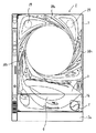
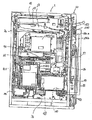
まず、遊技機の一例であるパチンコ遊技機の全体構成について説明する。図1はパチンコ遊技機を正面から見た正面図、図2はパチンコ遊技機1の遊技領域を正面から見た正面図、図3はパチンコ遊技機1の内部構造を示す全体背面図である。
【0025】
図1に示すように、パチンコ遊技機1は、縦長な方形状に枠組形成される外枠2aと、該外枠2aの内側に開閉可能に軸支されかつパチンコ遊技機1の主要構成部が集約して設けられる前面枠2bと、該前面枠2bの前面上部に開閉自在に軸支されて設けられる額縁状のガラス扉枠2とから構成されている。ガラス扉枠2の下部表面には打球供給皿3が設けられている。前面枠2bにおいて、打球供給皿3の下部には、打球供給皿3から溢れた貯留球を貯留する余剰球受皿4と打球を発射する打球操作ハンドル(操作ノブ)5とが設けられている。また、ガラス扉枠2の後方に位置する前面枠2bには、前面側に遊技領域7が形成された遊技盤6が着脱可能に設けられている。前面枠2bおよびガラス扉枠2は、パチンコ遊技機1の正面から見て左側の端部において軸支され、軸支位置を開閉軸として開閉される。ガラス扉枠2には、遊技盤6の遊技領域7をほぼ透視し得る透視窓が開設され該透視窓の裏面からガラス板が装着されている。遊技領域7の外側の左右上部には、効果音を発する2つのスピーカー27が設けられている。遊技領域7の外周には、遊技効果ランプ28a,28b,28cが設けられている。
【0026】
図2に示すように、遊技領域7の中央付近には、液晶表示器よりなる特別図柄表示部9と遊技演出にあわせて作動する役物77と演出選択画面等で遊技者からの指示選択を検出する光センサ61,62とを含む可変表示装置8が設けられている。なお、光センサについては図5等を用いて詳述する。
【0027】
また、特別図柄表示部9の表示画面には、始動記憶の表示と普通図柄の可変表示が演出内容・図柄変動等とあわせて表示されるように構成されている。この始動記憶の表示点灯数により、特別図柄を始動させるための始動入賞口14への入賞数が記憶されている数を遊技者は認識できる。また、遊技領域内にはゲート通過記憶表示器41が設けられている。このゲート通過記憶表示器41のLEDの点灯している数により、普通図柄を始動させるための通過ゲート11への遊技球の通過数が上限を4として記憶されていることが表示される。
【0028】
遊技領域7の左右周辺には、遊技中に点灯表示される装飾ランプ25が設けられ、下部には、入賞しなかった打球を吸収するアウト口26がある。
【0029】
遊技が開始された際の打球発射装置34から発射された打玉は、誘導レール76を通って遊技領域7に入り、その後、遊技領域7を流下してくる。打球が通過ゲート11を通ってゲートスイッチ12で検出されると、特別図柄表示部9内に表示される普通図柄の表示が変動する状態になる。また、打球が始動入賞口14に入り始動口スイッチ17で検出されると、図柄の変動を開始できる状態であれば、特別図柄表示部9内の図柄回転を始める。図柄の変動を開始できる状態でなければ、特別図柄表示部9内に表示される始動入賞記憶の表示点灯数を1増やす点灯表示がなされる。
【0030】
特別図柄表示部9内の映像の回転は、一定時間が経過したときに停止する。停止時の画像の組合せ(たとえば、111,777等のゾロ目)が大当り図柄の組合せであると、大当り遊技状態に移行する。すなわち、大入賞口20が、一定時間経過するまで、または、所定個数(たとえば10個)の打球が入賞するまで開放する。そして、大入賞口20の開放中に打球が特定入賞領域に入賞しVカウントスイッチ22で検出されると、継続権が発生し大入賞口20の開放が再度行なわれる。継続権の発生は、所定回数(たとえば15ラウンド)許容される。
【0031】
次に、パチンコ遊技機1の裏面の構造について図3を参照して説明する。パチンコ遊技機1の遊技盤6の裏側には、前面枠2bが設けられており、さらに向かって手前に機構板36が備えられている。前面枠2bには、特別図柄表示部9の表示制御を行なう表示制御基板80、基板ケース32に覆われ遊技制御用マイクロコンピュータ等が搭載された遊技制御基板31、およびパチンコ玉の払出制御を行なう払出制御用マイクロコンピュータ等が搭載された賞球基板37が設置されている。さらに、モータの回転力を利用して打玉を遊技領域7に発射する打球発射装置34と、スピーカー27および遊技効果LED・ランプ28a,28b,28cに信号を送るためのランプ制御基板35が設けられている。一方、機構板36の上部には玉タンク38が設けられ、パチンコ遊技機1が遊技機設置島に設置された状態でその上方からパチンコ玉が玉タンク38に供給される。玉タンク38内のパチンコ玉は、誘導樋39を通って玉払出装置に供給される。
【0032】
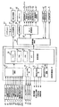
図4は、遊技制御基板31における回路構成の一例を示すブロック図である。また、図4には、払出制御基板37、ランプ制御基板35、音制御基板70、発射制御基板91および表示制御基板80が示されている。遊技制御基板31には、プログラムに従ってパチンコ遊技機1を制御する遊技制御用マイクロコンピュータ53と、ゲートスイッチ12、始動口スイッチ17、Vカウントスイッチ22、カウントスイッチ23、入賞口スイッチ19a、満タンスイッチ48、球切れスイッチ187、球切れ検出スイッチ167、および賞球カウントスイッチ301Aからの信号を遊技制御用マイクロコンピュータに与えるスイッチ回路58と、入賞球装置15を開閉するソレノイド16と大入賞口20の開閉板を開閉するソレノイド21および役物キャラクタ77を作動させるソレノイド13を遊技制御用マイクロコンピュータ53からの指令に従って駆動するソレノイド回路59とが搭載されている。
【0033】
遊技制御用マイクロコンピュータ53は、ゲーム制御用のプログラム等を記憶するROM54、ワークメモリとして使用される記憶手段の一例であるRAM55、制御用プログラムに従って制御動作を行なうCPU56およびI/Oポート部57を含む遊技制御用のマイクロコンピュータである。この実施の形態ではROM54,RAM55はCPU56に搭載されている。すなわち、CPU56は1チップマイクロコンピュータである。なお、CPU56とROM54,RAM55とは1チップ化されていなくてもよい。つまり、ROM54、RAM55およびI/Oポート部57は外付けであっても内蔵されていてもよい。また、I/Oポート部57は、マイクロコンピュータにおける情報入出力可能な端子である。
【0034】
また、本実施形態における特別図柄を可変表示する特別図柄表示部9の表示制御は、表示制御基板80に搭載されている表示制御手段である表示制御用マイクロコンピュータ800によって行われる。遊技制御基板31から表示制御基板80には、可変表示装置8の表示,ランプの点灯,遊技音発生等の演出の制御に関する指令情報として表示制御コマンドが伝送される。表示制御基板80では、伝送されてきた表示制御コマンドに応じて特別図柄表示部9の表示制御を行なう。さらに、表示制御基板80は、光センサ61,62で検出された信号が入力され、その指定値により後述する演出態様等の変更を行なうことができる。また、表示制御基板80では、その伝送されてきた表示制御コマンドの解析がなされ、選択されている演出,光センサ61,62からの入力信号等にもとづいてランプ・音制御コマンドを設定し、それぞれランプ・音制御制御基板に出力される。
【0035】
また、ランプ制御基板35に搭載されているランプ制御手段ではランプ制御用マイクロコンピュータにより、遊技効果LED28a、賞球ランプ51、球切れランプ52、ゲート通過記憶表示器41、役物飾りランプ1115および、装飾ランプ25の点灯制御が行なわれる。すなわち、表示制御基板80から伝送されるランプ制御コマンド等の情報にしたがい、ランプ制御用マイクロコンピュータがランプ制御コマンドに応じて制御対象機器を駆動する制御を行なう。
【0036】
また、音制御基板70には、音制御用マイクロコンピュータが搭載されており、この音制御用マイクロコンピュータが、音制御コマンドに応じてスピーカー27からの出力される遊技音等の制御を行なう。表示制御基板80から伝送される音制御コマンド等の情報にしたがい、音制御用マイクロコンピュータが、音制御コマンドに応じて制御対象機器を駆動する制御を行なう。
【0037】
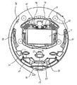
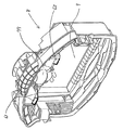
図5は、本実施形態による可変表示装置8を右上から見た斜視図を示す図である。図5においては、図1に示された可変表示装置8と共通する部分については同一の参照番号を付し、その説明を省略する。
【0038】
図5を参照して、本実施形態の可変表示装置8においては、特別図柄表示部9の左上部に、遊技者により画面表示上の左側の選択肢(たとえば、「サッカーモード」の選択肢)の選択を検出するための第1の光センサ61が斜め下方向に向け設けられ、特別図柄表示部9の右上部に、遊技者により画面表示上の右側の選択肢(たとえば、「野球モード」の選択肢)の選択を検出するための第2の光センサ62が斜め下方向に向け設けられている。光センサ61,62の各々は、光を前方へ投光する投光部、投光に応じて物体により反射した光を受光する受光部、および、受光部における反射光を受光した受光スポットの位置にもとづいて前方に存在する物体までの距離を算出し所定距離範囲内の物体の有無を検出する演算検出部とを含み、センサの前方の所定距離範囲内に物体(たとえば、遊技者の指先)を検出した場合に検出信号を出力する。なお、この光センサ61,62からの検出信号は、前述した遊技制御基板31を経ることなく、前述した表示制御基板80に直接的に入力される。これにより、遊技制御基板31に入力信号が入力されないため不正防止を図れる。
【0039】
本実施形態で用いる光センサ61,62は、上述したように簡易な構造であるため、省スペース化を実現でき可変表示装置8のデザインを損なうことなく組み込みやすくなる。また、物体を検出する方法が物体からの反射光を受光部で受光した際の受光スポットの位置により物体までの距離を計測し、その物体までの距離が所定距離範囲内にあるか否かで検出を行なう(測距式)ため、受光量で検出を行なうセンサと比較して、物体固有の反射率に影響を受けず確実に検出できる。さらに、検出可能な反射率を人間(遊技者)の肌の反射率(約40パーセント)を含む値に設定可能であるため、髪の毛や衣服で検出される誤検出の発生が極度に防止でき検出の精度を高めることができる。さらに、物体の有無を検出することができる範囲を示す所定距離範囲を設定することができるため、遊技場必要としない距離にある物体、たとえば遊技台から1m離れた物体等を検出してしまう誤検出を防止することも可能となる。具体的には、図6を参照し説明する。
【0040】
図6は、パチンコ遊技機1の可変表示装置8の横断面図であり、これを参照し本実施形態で用いるセンサの検出方法を段階的に説明する。なお、図6では、ガラス扉枠2のガラス板2’と、光センサ61からの投射光を実線で、物体に衝突後の反射光を点線で表わしている。
【0041】
まず、図6(a)では、透過部材の性質を考慮せずに基本的な検出の仕組みを説明する。光センサ61の投射部から投射された投射光は、ガラス板2’を透過しパチンコ遊技機1の外部に放たれる。外部に放たれた投射光路上の所定距離範囲内に遊技者が指を移動させることにより、投射光が指に衝突し反射する。その反射した反射光が再びガラス板2’を透過しパチンコ遊技機1の内部に進入し、光センサ61の受光部で受光される。その際に、光センサは、受光した受光スポットの位置にもとづき、反射点である遊技者の指までの距離が所定距離範囲内であったか否かを判別し所定距離範囲内であった場合には、表示制御基板80に入力信号を出力するように構成されている。
【0042】
次に、透過部材の性質を考慮した場合を図6(b)を参照し説明する。まず、透過部材は、光が該透過部材を透過(貫通)する場合にその光の一部を反射させ光路を変更させる性質を有している。本実施形態では、ガラス板2’が透過部材であるため図6(a)を参照し説明したように、たとえば、物体固有の反射率を考慮せず、また、光センサの検出可能な所定距離範囲をある程度調整しなければ図6(b)に示すような誤検出を発生することとなる。投射光がガラス板2’に衝突した際に、投射光の一部がパチンコ遊技機1の外部に放出されることなく内部に反射し、遊技機部品(たとえば、特別図柄表示部9の表示面)に衝突し、その衝突による反射光の一部が再びガラス板2’により反射され光センサの受光部で受光される。これにより、光センサは常に遊技機部品(たとえば、特別図柄表示部9の表示面)を誤検出してしまう可能性が有り、本来必要とする遊技者の指が光路上に移動されているか否かの検出が不可能となる。
【0043】
そこで、本実施形態では、上述した不都合を避けるために、光センサの検出可能となる反射率の範囲と所定距離範囲を独自に調節設定した光センサを使用している。これにより、センサ感度・検出精度の向上を実現している。
【0044】
すなわち、光センサの検出可能な反射率を人間の肌の反射率(約40パーセント)を含むように30パーセントから70パーセントの値に限定している。これにより、遊技者が反射率の高い白色の衣服を身に着けていたとしても反射率が高いため検出することはなく、逆に、遊技者が頭を下げた際に反射率の低い髪の毛を検出することもなく、光センサによる検出の精度を各段に向上させることができる。
【0045】
また、光センサが物体の有無を検出できる所定距離範囲を遊技者の手が届く範囲の距離、たとえば、ガラス板2’の前面側表面から5cmまで等のように限定している。これにより、遊技中、遊技者の顔を光センサが検出してしまうことがなく検出の信頼性が向上する。
【0046】
以上、独自の調節設定を行なった光センサを使用した場合について、具体的に図6(c)を参照し説明する。
【0047】
光センサから投射された投射光112は、ガラス板2’に衝突し反射した投射光111が生じる。その投射光111は、その投射光路上に位置する可変表示装置8やその他遊技機部品にA点で衝突し、その後は図6(b)の説明と同様、光センサで受光されることとなる。しかし、本実施形態で用いる光センサは、A点までの距離を所定距離範囲内に含めないように調節設定しているため、可変表示装置8やその他遊技機部品を検出した旨の検出信号が出力される場合はない。
【0048】
また、投射光112がガラス板2’を透過し、本実施形態で用いる光センサが設定されている所定距離範囲内で、限定している反射率の範囲内に含まれる遊技者の指に衝突し、それにより反射する反射光113は受光され、遊技者の指を検出した旨の検出信号が光センサから出力される。
【0049】
つまり、光センサの有効範囲を設定することで、ガラス板2’により反射した投射光111の光路上に存在する遊技機部品等の設置されている範囲以外の所定距離範囲内に存在する遊技者の指のみを検出可能としている。これにより、パチンコ遊技機1の部品自体を検出してしまうことはなく、誤検出を完全に防止することができる。なお、本実施形態では、光センサの検出可能な所定距離範囲を調節したが、これに限らず、光センサの設置位置・設置方向を調節する場合でもよく、透過部材により反射された投射光路上の、遊技機部品が設置されている範囲以外の所定距離範囲の物体のみを検出可能にするものであればよい。
【0050】
また、光センサの検出可能な反射率の数値を限定することで、光センサの設定されている反射率範囲内でなければ、投射光路上に物体が存在してもその物体を検出した旨の検出信号が光センサから出力されることはない。これにより、光センサに検出をさせようとする遊技者自らの意思がない場合には、前述したように遊技者の衣服や髪の毛を偶然誤って検出することもなく、極めて検出精度の高い状態で遊技を行なうことができる。このように光センサの検出精度を高めることにより後述する演出選択においても、左の選択肢を選択したにもかかわらず、右の選択肢を選択していたりまたは何の選択もされていないといった不都合は生じず、演出選択を十分に楽しむことができ、遊技に対する興趣をさらに増すことができる。
【0051】
図7は、後述する演出選択時の特別図柄表示部9の表示画面と光センサ61,62の検出可能範囲との関係を説明するための図であり、いずれも遊技者が正面位置から表示画面を見た場合を示している。
【0052】
まず、図7(a)は、演出選択時の特別図柄表示部9の表示画面を示している。左の選択肢が「変更するよ」の文字を四角で囲みボタンのように表示されており、右の選択肢も「変更しません」の文字を四角で囲みボタンのように表示されている。
【0053】
また、図7(b)は、演出選択時に光センサ61,62の判定が有効になった場合のガラス板2’前面における有効検出範囲を図面上だ円で囲い示している。
【0054】
次に、図7(c)は、前述した図7(a)と(b)を重ね合わせて示している。本実施形態においては、光センサ61の有効検出範囲をガラス板2’前面側で検出可能とし、かつ、その有効検出範囲を遊技者が正面位置から見た場合に左の選択肢の表示と重なるように設定している。光センサ62の有効検出範囲についても同様に右の選択肢の表示と重なるように設定している。すなわち、遊技者が演出選択画面の表示を見た場合に、特別図柄表示部9に表示される選択肢と光センサ61,62の有効検出範囲が互いに重なり合うようにそれぞれ設定されている。これにより、遊技者は、選択したい選択肢の表示を押すような感覚でガラス前面に指を移動させるだけで、目視することはできない光センサの有効検出範囲に指を自動的に移動させることができ、指を検出した光センサから検出信号が出力される。つまり、特別図柄表示部9の表示画像と光センサ61,62の有効検出範囲がそれぞれリンクするように設定しているため、遊技者にとって演出選択時の遊技の進行方法・光センサの検出方法を容易に理解することができ興趣が増す。また、ガラス板2’自体をタッチセンサにするよりも、安価かつ制御負担の軽減が図れる構成とすることができる。
【0055】
さらに、本実施形態においては、演出選択画面において表示されている左側と右側の選択肢の表示数に光センサの数を対応させている。これと同様に、選択肢が3つ以上ある場合(第2実施形態参照)でも、その選択肢に対応した光センサを検出させることで選択できる。これにより、一回の選択作業でいずれの選択肢についても選択可能となり、選択肢を複数設けた場合であっても選択作業が面倒になる不都合は生じず、演出選択の選択肢の項目を多様に設定することが可能となる。
【0056】
また、上述のように、複数の光センサを設けた場合であっても、各々の光センサの検出範囲が重ならないように設定設置しているため、複数の光センサにおいて同時に検出がなされる場合はなく誤検出の防止につながる。なお、本実施形態では、仮に複数の検出信号が同時に出力されたとしても、表示制御基板80には誤検出時事前決定処理手段が組み込まれており、誤検出が発生した場合は予め設定している入力値を採用するため、不都合は発生しない。
【0057】
なお、光センサは、可変表示装置8に限らず、たとえば、可変入賞球装置15等、遊技領域7内において遊技者が選択可能となる場所であればどのような場所に設けてもよい。前述したように光センサの所定距離範囲をガラス扉枠2のガラス板2’より外部側に設定しておけば、打玉の流下経路途中であっても打玉を検出することはなく、遊技演出との関連性を考慮した場合にさまざまな配置パターンを実現でき、そのデザインを見た遊技者は該遊技台に興味を示し興趣を向上させることができる。
【0058】
さらに、この本実施形態においては、次のような効果を得ることができる。前述のような遊技者による選択を検出するために、遊技者に非接触で選択の検出を行なって選択に関する信号入力を行なう光センサのような非接触入力手段を用いたことにより、物理的なスイッチ(たとえば、押しボタンスイッチ)のように遊技者に接触する態様で選択の検出を行なって選択に関する信号入力を行なう接触入力手段を用いる場合と比較して、装置が物理的に破損するおそれが少なくなる。また、光センサのような非接触入力手段を遊技領域7に設けたことにより、遊技機の枠(たとえば、ガラス扉枠2、前面枠2b)を共通化することができる。これにより、遊技機の機種変更を行なう場合には遊技盤を新しいものに交換するに際して遊技枠ごと新しいものに交換せずに遊技盤のみを交換することで足りるようにすることができる。
【0059】
図8は、パチンコ遊技機1の遊技制御に用いられる乱数を生成するための各種ランダムカウンタを示す図である。図8は、ランダムカウンタの例として、R1、R2、R3−1、R3−2、R3−3、および、R4の乱数を発生させるためのランダムカウンタがそれぞれ示されている。
【0060】
このパチンコ遊技機1は、前述した大当り状態を発生させるか否か等をランダムカウンタのカウント値(乱数)によりランダムに決定する。以下に、ランダムカウンタの代表例を示す。
【0061】
R1は、特別図柄表示部9の表示結果に基づいて特定遊技状態としての大当りを発生させるか否かをランダムに決定するためのものである。
【0062】
R2は、大当り事前決定時の停止図柄(左,中,右が同一の停止図柄)を決定するために用いられるランダムカウンタ(または大当り図柄決定用乱数そのものを示す場合もある)である。
【0063】
R3−1、R3−2、R3−3は、R1によりはずれと決定された場合に、特別図柄表示部9に停止表示される左、中、右のはずれ図柄を事前決定するために用いられるランダムカウンタである。
【0064】
R4は、特別図柄が可変表示される際の変動種類(変動パターンの種類)を決定するためのランダムカウンタであり、0から加算更新されてその上限である250まで加算更新された後再度0から加算更新される。このR4は、タイマ割込み毎(0.002秒毎)および、割込み処理余り時間毎に1ずつ加算される。なお、変動パターンについては、R1、R2、R3により抽出した値によって利用するテーブルの種類が決まり、R4により抽出された値を添字として対応するパターンテーブルをルックアップする。この点については後で詳述する。
【0065】
以上に示したランダムカウンタは、カウンタ別に定められた抽出条件の成立に応じてランダムなタイミング(たとえば始動入賞発生時等)でデータが抽出される。これにより、各ランダムカウンタから抽出されたデータは、ランダムな値(乱数値)になる。
【0066】
なお、図示を省略したが、特別図柄表示部9の表示画面中で表示される普通図柄の表示結果もランダムカウンタにより決定される。そのランダムカウンタは、たとえば、2msec毎に1ずつ加算されるものであり、0からカウントアップして上限である10までカウントアップした後再度0からカウントアップし直す。このランダムカウンタのカウント値は、普通図柄の表示結果に基づいて発生する普通当りを発生させるか否かをランダムに決定するためのものである。ゲートスイッチ12によりゲート通過検出がされると、それに応じてランダムカウンタのカウント値が抽出される。そして、ゲート通過検出がされた場合は、その抽出されたランダムカウンタの値が、普通当り判定値(たとえば「2」)と一致するか否かの判断がなされ、一致した場合に普通当りを発生させる制御が行なわれる。普通当りが決定された場合には、それに応じて普通当りに該当する停止図柄が決定され、はずれが決定された場合には、その他のランダムカウンタを用いて普通図柄の停止表示結果が決定される。
【0067】
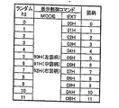
図9は、遊技制御基板31から表示制御基板80へ伝送される演出制御コマンドとしての表示制御コマンドデータとランダム3カウンタの抽出値との対応関係を記憶しているテーブルである。この図9のテーブルは、遊技制御基板31内のROM54により記憶されている。
【0068】
コマンドデータは、2バイトデータで構成されており、上位1バイトによりMODEデータが構成され、下位1バイトによりEXTデータが構成されている。MODEデータは、当該コマンドデータが何を指令するデータかを大まかに特定するためのデータである。EXTデータは、コマンドの具体的内容を指定するためのデータである。
【0069】
ランダム3−1〜ランダム3−3の抽出値がたとえば「0」の場合には、EXTデータが00Hとなり、抽出値が「1」の場合にはEXTデータが01Hとなり、抽出値が「11」の場合にはEXTデータが0BHとなる。したがって、たとえばランダム3−3の抽出値が「5」であった場合には、表示コマンドは92H05Hとなる。
【0070】
図10は、変動開始コマンドによって特定される可変表示装置8の可変表示の表示時間および可変表示パターンを説明するための図である。変動開始コマンドは、MODEデータは「80H」であり、EXTデータは「01H」「02H」「03H」…「86H」「87H」であり、番号それぞれに対応する可変表示装置8の可変表示の表示時間はT1,T2,T3…T135,T136であり、また、可変表示パターンは、「通常変動はずれ」、「リーチAはずれ」、「リーチA当り」…「リーチFはずれ」、「リーチF当り」等である。
【0071】
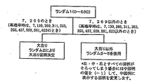
図11は、パチンコ遊技機1の大当り制御を行なうための概略を示すフローチャートである。まず、0〜630の範囲でカウントするランダムカウンタR1のカウント数を抽出する。
【0072】
高確率時でない通常時では、その抽出値が「7」または「269」のときには大当りを発生させることが事前決定され、R2からデータを抽出し、その抽出値に基づいて、特別図柄表示部9に表示される大当り図柄が決定される。一方、R1の抽出値が「7」または「269」以外のときには、はずれが事前決定され、R3−1、R3−2、R3−3からデータを抽出し、その抽出値に基づいて特別図柄表示部9に表示されるはずれ図柄が決定される。ここで、この決定されたはずれ図柄が偶然ゾロ目の図柄であった場合には、R3−2の抽出値を「1」減算し、強制的にはずれ図柄にして表示制御する。
【0073】
一方、高確率時の場合には、R1の抽出値が7,139,269,311,353,395,437,509,581,623のときに大当り状態を発生させることが決定される。一方、高確率時においてランダム1の抽出値が上記カウンタ値以外のときに、はずれが事前決定される。
【0074】
図12は、前述した変動パターンテーブルの選択決定処理の1例をフローチャートで示したものである。まずSa1において、R1の抽出値が大当り状態を発生させるカウンタ値であるか、または、はずれ状態となるカウンタ値であるか判断がなされる。
【0075】
抽出値が大当り状態を発生させるカウンタ値であった場合は、Sa2により大当り用の変動パターンテーブルを選択し、選択した変動パターンテーブルをルックアップしR4により抽出された値の変動パターンが設定される。
【0076】
抽出値がはずれ状態となるカウンタ値であった場合は、Sa3によりR2で抽出された値にもとづき左・中・右の各図柄が設定され、Sa4において設定された各図柄がリーチ状態となり得るか否かを判断する。かかる判断によりSa5、Sa6では、それぞれリーチはずれ用変動パターンテーブルかはずれ用変動パターンテーブルかのいずれかのテーブルを選択し、選択した変動パターンテーブルをルックアップしR4により抽出された値の変動パターンが設定される。
【0077】
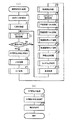
図13は、遊技制御基板31により実行される遊技制御メイン処理および割込処理を示すフローチャートである。図13において、(a)は遊技制御メイン処理が示され、(b)に割込処理が示されている。この割込処理は、たとえば2msec毎に1回実行される。
【0078】
遊技制御メイン処理においては、S1により、スタックポインタの設定がなされる。これは、スタックポインタの指定アドレスをセットするためのスタックセット処理である。次にS2により、初期化処理が行なわれる。初期化処理では、RAM55にエラーが含まれているか判定され、エラーが含まれている場合には、RAM55を初期化することおよび各種フラグの初期化設定などの処理が行なわれる。さらに、初期化処理では、後述する割込処理を実行するタイミングを規定するタイマ割込時間(たとえば2msec)をCPU56に設定する処理がなされる。これにより、電源投入等によるリセット後、初めての割込処理を行なう際、実行タイミング規定のために計時が開始される。また、初期化処理においては、種々のタイマがセットされるとともに、表示制御基板80のサブ基板初期化コマンドを出力する処理が行なわれる。
【0079】
次に、確定図柄(予定停止図柄)を決定する等のためのR3、R4更新処理がS3により行なわれる。このパチンコ遊技機1においては、可変表示装置8の可変表示での特別図柄の確定図柄が乱数(ランダムカウンタのカウント値)に基づいて決定される。このS3では、そのように停止図柄を決定するための表示用乱数が更新される。次にS4により、タイマ割込ありか否かの判断がなされる。タイマ割込がない場合にはS3へ戻り、S3とS4とによる無限ループにより表示図柄乱数の更新処理が繰返し実行される。
【0080】
一方、タイマ割込処理は、初期化処理で規定されたタイマ割込時間(たとえば2msec)毎に実行され、S17によりタイマ割込ありが設定され、S18により割込許可処理がなされる。その結果、S4によりYESの判断がなされ、S5に進み、タイマ割込なしが設定され、S6〜S16の処理が実行されることとなる。このS6〜S16の処理が実行された後にはS3へ制御が進み、S5によるタイマ割込なしが設定されているために、S3,S4のステップを無限ループで繰返し実行することとなる。この状態で再度2msecの時間が経過すれば、タイマ割込処理によるタイマ割込ありの設定に従ってS4によりYESの判断がなされて、S5〜S16の処理が実行されることとなる。
【0081】
S6では、ゲートスイッチ12、始動口スイッチ17、Vカウントスイッチ22、カウントスイッチ23等の状態を入力し、各入賞口や可変入賞球装置に対する入賞があったか否か等を判定するスイッチ処理がなされる。始動口スイッチ17により始動入賞が検出された場合には、このスイッチ処理において、始動記憶処理が実行される。
【0082】
次に、S7によりエラー処理がなされる。このエラー処理は、パチンコ遊技機1の内部に備えられている自己診断機能によって種々の異常診断を行ない、その結果に応じて必要ならば警報を発生させる等の処理である。
【0083】
次にS8へ進み、乱数更新処理がなされる。これは、遊技制御に用いられる各種の判定用乱数を示す各ランダムカウンタを更新する処理である。具体的には、R1のカウンタの更新処理である。
【0084】
次にS9へ進み、表示図柄乱数の更新処理が行なわれる。この処理は、S3と同じ処理であり、具体的には、ランダム3−1,ランダム3−2,ランダム3−3を更新する処理である。
【0085】
次にS10へ進み、特別図柄プロセス処理がなされる。この特別図柄プロセス処理では、複数ある処理のうち1つが特別図柄プロセスフラグの値に従って選択されて実行される。そして、特別図柄プロセスフラグの値は、遊技状態に応じて各処理中において更新される。次に、普通図柄プロセス処理がS11により行なわれる。この普通図柄プロセス処理では、特別図柄表示部9の表示画面に表示される普通図柄の可変表示を所定の順序で制御するための普通図柄プロセスフラグに従って該当する処理が選び出されて実行される。そして、普通図柄プロセスフラグの値は、遊技状態に応じて各処理中に更新される。
【0086】
次にS12に進み、特別図柄コマンド処理が実行される。この特別図柄コマンド処理は、前述した特別図柄表示用のコマンドデータを遊技制御基板31が表示制御基板80へ伝送する処理である。次にS13へ進み、普通図柄コマンド処理が実行される。この普通図柄コマンド処理は、特別図柄表示部9の表示画面に表示される普通図柄の可変表示を表示制御するためのコマンドデータを遊技制御基板31が表示制御基板80に伝送する処理である。
【0087】
次にS14へ進み、情報出力処理がなされる。この情報出力処理は、情報出力回路64を介して前述した確変情報、大当り情報、始動情報を外部出力する処理である。次にS15へ進み、ソレノイド出力処理がなされる。このソレノイド出力処理は、前述したソレノイド16,21を励磁制御するための制御信号をソレノイド回路59へ出力するための処理である。次にS16へ進み、賞球処理がなされる。この賞球処理は、遊技制御基板31が賞球基板37に対し賞球個数信号と賞球可能信号とを送信して、賞品球の払出指令を行なうための処理である。このS16の後制御がS3へ進む。
【0088】
図14は、S10により示された特別図柄プロセス処理のサブルーチンプログラムを示すフローチャートである。この特別図柄プロセス処理は、特別図柄用プロセスフラグの値に応じて、10種類の処理(SA01〜SA10)の内、いずれかが実行されるように制御される。SA01〜SA10において、以下のような処理が実行される。
【0089】
SA01において、特別図柄変動待ち処理が行なわれる。始動入賞口14(この実施の形態では可変入賞球装置15の入賞口)に打玉が入賞して始動口スイッチ17がオンするのを待つ。始動口スイッチ17がオンすると、始動入賞記憶数が満タンでなければ、始動入賞記憶数を「1」加算更新するとともに大当り判定用乱数を抽出する。
【0090】
SA02において、特別図柄判定処理が行なわれる。特別図柄の可変表示が開始できる状態になると、始動入賞記憶数を確認する。始動入賞記憶数が0でなければ、抽出されている大当り判定用乱数の値に応じて、大当りとするかはずれとするかを決定する。
【0091】
SA03において、停止図柄設定処理が行なわれる。左右中図柄の停止図柄を決定する。
【0092】
SA04において、変動パターン設定処理が行なわれる。大当りか否かの判定結果およびリーチ判定用乱数の値等に応じた変動パターンテーブルをルックアップし、変動パターン決定用乱数の値に応じて変動パターンを決定する。すなわち、図12等に示された処理が実行される。
【0093】
SA05において、全図柄変動開始処理が行なわれる。特別図柄表示部9において全図柄が変動開始されるように制御する。このとき、表示制御基板80に対し表示制御コマンドとして、変動パターンコマンドと、左右中予定停止図柄(最終停止図柄)をそれぞれ指令する左,中,右の3つの停止図柄コマンドとが送信される。
【0094】
SA06において、全図柄停止待ち処理が行なわれる。所定時間が経過すると、特別図柄表示部9において表示される全図柄が停止されるように制御する。また、全図柄停止のタイミングまで、所定のタイミングで左右図柄が停止されるように制御する。
【0095】
SA07において、大当り表示処理が行なわれる。R1にもとづく抽出値が大当り状態を発生させる値であった場合には、R2により抽出された値に対応した表示制御コマンドが表示制御基板80に送信されるように制御するとともに内部状態(プロセスフラグ)をステップSA08に移行するように更新する。そうでない場合には、内部状態をステップSA10に移行するように更新する。また、遊技制御基板80の表示制御用マイクロコンピュータは表示制御コマンドのデータに従って、特別図柄表示部9に大当り表示を行なう。大当り表示は遊技者に大当りの発生を報知するためになされるものである。
【0096】
SA08において、大当り中ラウンド表示処理が行なわれる。特別図柄表示部9に大当り中のラウンドを表示する制御を開始する。
【0097】
SA09において、大入賞口開放中V表示処理が行なわれる。大当り中ラウンド表示の表示制御コマンドデータを表示制御基板80に送信する制御等を行なう。大入賞口の閉成条件が成立したら、大当り遊技状態の継続条件が成立していれば内部状態をSA08に移行するように更新する。大当り遊技状態の終了条件が成立していれば、内部状態をSA10に移行するように更新する。
【0098】
SA10において、大当り終了表示処理が行なわれる。大当り遊技状態が終了したことを遊技者に報知するための表示を行なう。この表示が終了したら、内部フラグ等を初期状態に戻し、内部状態をSA01に移行するように更新する。
【0099】
前述したように、始動入賞口14に打玉が入賞すると、遊技制御基板31は、特別図柄プロセス処理において、大当りとするかはずれとするかの決定、停止図柄の決定、変動表示期間の決定等を行ない、その決定に応じた表示制御コマンドおよびINT信号を表示制御基板80に向けて出力する。表示制御基板80側の表示制御用マイクロコンピュータは、遊技制御基板31からの表示制御コマンドに応じて特別図柄表示部9の表示制御を行なう。
【0100】
図15は、(a)が表示制御メイン処理を示すフローチャートであり、(b)がタイマ割込処理を説明するためのフローチャートである。表示制御メイン処理においては、SB01において、初期化処理が行なわれる。この初期化処理においては、RAMに記憶されている記憶内容すべてが消去され、新たに各パラメータの初期値(たとえば、「0」)が設定される。
【0101】
次に、SB02においてタイマ割込フラグがセットされているか否かが判別される。タイマ割込フラグがセットされていなければSB02に戻り、タイマ割込フラグがセットされていれば、SB03に進みタイマ割込フラグをクリアしてからSB04においてコマンド解析処理を行なう。SB04のコマンド解析処理においては、遊技制御基板31から送信されてきたコマンドを受信して、いかなるコマンドであるかを解析し、可変表示装置8に表示するための図柄をセットする処理が行なわれる。
【0102】
次に、SB05においては、表示制御プロセス処理が行なわれる。この表示制御プロセス処理は、図19を用いて後述するが、可変表示装置8に表示させるための変動開始コマンド受信待処理、選択遊技判定処理、可変表示動作開始処理、図柄変動中処理、全図柄停止待ち処理、および大当り表示処理等の処理が行なわれる。SB06においては、音・ランプ制御コマンド処理が行なわれる。この音・ランプ制御コマンド処理は、前述したように、遊技制御基板31から表示制御基板80に伝送されてきた変動パターンコマンドと特別図柄表示部9で表示されている演出の種類(ゲームモード)、さらに、光センサ61,62からの検出信号にもとづき遊技音やランプ点灯パターンなどについてのコマンドの設定がなされ、それぞれ対応した音・ランプ制御基板に伝送される処理が行なわれる。これにより、同期のとれた演出を行なうことができる。また、図15の(b)においてはタイマ割込処理が行なわれ、SB07においてタイマ割込フラグがセットされている。このタイマ割込は33msec秒ごとに行なわれる。そして、SB08において、タイマ割込許可がなされてタイマ割込処理を終了する。なお、タイマ割り込み処理は、33msec経過する毎に1回行なわれる。
【0103】
図16は、ランダムカウンタ抽出値成立条件を満たした場合、遊技制御基板31にコマンドを記憶するRAM55の記憶領域である図柄変動バッファ記憶領域を説明するための図である。ランダムカウンタ抽出値成立条件を満たすごとに、抽出値に対応する各図柄変動コマンドが記憶される。
【0104】
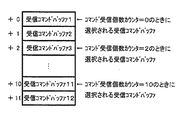
図17は、遊技制御基板31から送信されてきたコマンドを記憶する表示制御用マイクロコンピュータのRAM101a(記憶領域)である受信コマンドバッファ記憶領域を説明するための図である。遊技制御基板31から送信されてきたコマンドを表示制御基板80が受信するごとに、受信個数カウンタが0からカウントアップされる。そして、コマンド受信個数カウンタが0のときには受信コマンドバッファ1が選択されて、その受信コマンドが記憶される。
【0105】
図18は、遊技制御基板31から出力されてきたコマンドが入力された表示制御基板80において行なわれるコマンド解析処理を説明するためのフローチャートである。図18に示すコマンド解析処理においては、SD01〜SD08において、コマンド受信バッファに受信コマンドがあるか否か、左中右の図柄の指定コマンドであるか否かを判別し、各図柄停止格納エリアに図柄番号を格納する。
【0106】
また、SD07において受信コマンドが右図柄指定コマンドでなければSD09に進み、受信コマンドが変動パターン決定用コマンドであるか否かが判別される。SD09において、受信コマンドが変動パターン決定用コマンドであれば、SD10において変動パターンコマンドエリアに図柄番号を格納してSD01に戻る。
【0107】
また、SD09において受信コマンドが変動パターン決定用コマンドでなければ、SD11において受信コマンドがいかなるコマンドか判定して、対応したフラグをセットしてSD01に戻る。すなわち、変動開始コマンドであれば変動開始コマンドに対応したフラグをセットし、図柄確定コマンドであれば図柄確定コマンドに対応したフラグをセットするのである。
【0108】
図19は、表示制御プロセス処理を説明するためのフローチャートである。表示制御プロセス処理においては、SE01において変動開始コマンド受信待処理が行なわれる。変動開始コマンド受信待処理においては、コマンド受信割込処理によって、可変表示の時間および可変表示パターンを特定可能な変動開始コマンド(変動パターンコマンド)を受信したか否かを確認する。さらに、受信していなかった場合には、客待ちデモ時プロセス処理を行ない、本実施形態においては所定時間経過後に演出選択を行なうことができる。
【0109】
また、SE02においては、選択遊技判定処理が行なわれる。選択遊技判定処理においては、変動開始コマンド(変動パターンコマンド)に応じて、変動パターンコマンドが選択遊技可能となる特定変動パターンか、もしくは選択遊技を行なうことができない通常の変動パターンかを判断し、変動パターンを設定する。
【0110】
次に、SE03においては、可変表示動作開始設定処理が行なわれる。可変表示動作開始設定処理においては、変動パターンに対応したタイマをスタートさせ可変表示が開始されるように制御する。
【0111】
次に、SE04においては、図柄変動中処理が行なわれる。図柄変動中処理においては、変動パターンを構成する各変動状態(選択遊技、変動速度や背景、キャラクタ)の切替タイミングを制御するとともに、変動時間の終了を監視する。選択遊技を行なう場合はその場合の画面表示のタイミングを制御する。また左右図柄の停止制御を行なう。
【0112】
また、SE05においては、全図柄停止待ち処理が行なわれる。全図柄停止待ち処理においては、変動時間の終了時に、全図柄の停止を指示する図柄確定コマンドを受信していたら、図柄の変動を停止するための表示制御(図柄確定制御)を行なう。また、SE06においては大当り表示制御処理が行なわれる。大当り表示制御処理においては、変動時間の経過後、確変大当り表示または通常大当り表示するための制御を行なう。また、大当たり遊技終了後には演出選択遊技を行なうことができる。なお、本実施形態では、所定条件を満たした場合に、特別の演出態様に変更可能となる特典付与条件成立時の演出選択遊技が行なわれる。これについては、図25を用いて後述する。
【0113】
図20は、変動開始コマンド受信待ち処理を説明するためのフローチャートである。変動開始コマンド受信待ち処理においては、まず、表示制御用マイクロコンピュータは、左中右の特別図柄の変動が開始される指示を行なうとともに、可変表示時間および可変表示パターンを特定可能な変動開始コマンドを受信したか否かが確認される(SF01)。SF01において、変動開始コマンドを受信していなければ、SF03においては、客待ちデモ時プロセス処理が行なわれる。客待ちデモ時プロセス処理においては、変動開始コマンド(変動パターンコマンド)を受信していない場合に処理が行なわれ、その内容については図26を用いて詳述する。
【0114】
ここで、客待ちデモ時とは、たとえば、始動入賞があった場合に、その始動入賞に起因した特別図柄表示部9の導出動作が開始され、その後、可変表示の表示結果が表示されたにもかかわらず、その始動入賞以後に新たな始動入賞がないため、図柄の変動等が行なわれない状態時をいう。ただし、大当り状態は始動入賞に起因して発生する状態であることと遊技状態が待機状態ではないため、客待ちデモ時には含まれない。
【0115】
なお、電源投入後の未だ始動入賞が無い状態は、客待ちデモ時に含むと解する。たとえば、午前10時にパチンコ遊技機1の電源を投入しその日の午前11時まで始動入賞が一度も無く図柄変動が行なわれていないため客待ちデモ時には含まれないようにもとれるが、そうではなく、前日の午後10時前後までは始動入賞があり図柄変動が行なわれていたと考えるのが通常であり、前日の最後の始動入賞後図柄変動が行なわれ表示結果が導出されたにもかかわらず新たに当日11時まで始動条件が成立していない待機状態であることとなる。
【0116】
次に、変動開始コマンドを受信していれば、SF02において、プロセスフラグは選択遊技判定処理に設定されて変動開始コマンド受信待ち処理を終了するのである。この変動開始コマンドは、図10に示すいずれかである。したがって、可変表示時間および可変表示パターンを特定可能な変動開始コマンドを受信した場合には、表示制御プロセスフラグの値を選択遊技判定処理SE02に対応した値に変更するのである。
【0117】
図21は、選択遊技判定処理を説明するためのフローチャートである。図18に示すように、選択遊技判定処理においては、SG01において、遊技制御基板31から送信されてきた受信コマンドが選択遊技実行可能な特定変動パターンコマンドか否かを判定し、SG02、SG03でその受信した変動パターンコマンドに対応した変動パターンを設定する。SG04において、プロセスフラグは可変表示動作開始処理に設定されて選択遊技判定処理を終了するのである。設定された変動パターンの処理は、以下、図35、図36等を用いて詳細に説明する。
【0118】
図22は、可変表示動作開始設定処理を説明するためのフローチャートである。図22に示すように、可変表示動作開始設定処理においては、SH01において可変表示装置8の可変表示時間を計時するための可変表示時間タイマをスタートさせ、SH02において、設定された変動パターンおよび可変表示時間で、可変表示装置8において表示結果を導出表示するための可変表示を開始する。次にSH03において、プロセスフラグを図柄変動中処理に設定してから可変表示動作開始設定処理を終了する。
【0119】
図23は、図柄変動中処理を説明するためのフローチャートである。図柄変動中処理においては、SI01において、可変表示時間タイマがタイムアウトしているか否かが判別される。すなわち、表示結果を導出表示するための可変表示を終了するタイミングであるか否かが判別される。SI01において可変表示時間タイマがタイムアウトしていればSI02に進み、プロセスフラグを全図柄停止待ち処理に設定してから図柄変動中処理を終了するが、SI01において可変表示時間がタイムアウトしていなければそのまま図柄変動中処理を終了する。
【0120】
図24は、全図柄停止待ち処理を説明するためのフローチャートである。全図柄停止待ち処理においては、まず、SJ01において、左中右の図柄を停止させるための確定コマンドを受信しているか否かが判別される。SJ01において確定コマンドを受信していなければ全図柄停止待ち処理をそのまま終了するが、SJ01において確定コマンドを受信していればSJ02に進み、確定図柄を表示する。次に、SJ03において、確定図柄が大当り図柄であるか否かが判別される。SJ03において確定図柄が大当り図柄であればSJ04に進み、プロセスフラグを大当り表示処理に設定してから全図柄停止待ち処理を終了するが、SJ03において確定図柄が大当り図柄でなければSJ05に進み、プロセスフラグを変動開始コマンド受信待ち処理に設定してから全図柄停止待ち処理を終了する。
【0121】
図25は、大当り表示処理を説明するためのフローチャートである。大当り表示処理においては、まず、SK01において、大当りが確率変動状態を付随する確変大当りであるか否かが判別される。SK01において確変大当りでなければSK03に進み通常大当りであることを示す表示を行なってからSK04に進むが、SK01において大当りが確変大当りであればSK02に進み確変大当りであることを示す表示を行なってからSK04に進む。
【0122】
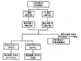
SK04においては大当り遊技が終了したか否かが判別される。SK04において大当り遊技が終了していなければ大当り表示処理をそのまま終了するが、SK04において大当り遊技が終了していればSK05に進み今回の大当りが開始される前の遊技状態が高確率で大当りとなる確変状態であったのか、低確率状態で大当りとなる通常状態であったのかが判別される。SK05において確変状態であった場合はSK08へ進み、図26のSL04で行なわれる演出選択プロセス処理がなされる。このように、大当たり後に演出選択遊技が可能であることより、演出の変更契機が遊技者にとってわかりやすく、大当たりに付加価値が生じ興趣が増す。なお、処理内容については、デモ時プロセスフラグを用いない以外は同じであるので別途の説明は省略する。
【0123】
続いて、通常状態であった場合はSK06に進み前回の大当り終了時から今回の大当りになるまでの図柄変動回数が50回未満であるか否かが判別される。SK06において50回未満でなかった場合はSK08へ進み、50回未満であった場合はSK07へ進み、図32を用いて後述する特典付与条件成立時の特別演出選択プロセス処理を行なうことができる。SK09では、プロセスフラグを変動開始コマンド受信待ち処理に設定し大当り表示処理を終了する。なお、大当り遊技とは、特定遊技状態となっている期間のことである。
【0124】
次に、図20のSF03で行なわれる客待ちデモ時プロセス処理の処理内容を説明する。図26は客待ちデモ時プロセス処理の処理内容を示すフローチャートである。
【0125】
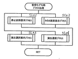
まず、SL01においては停止図柄表示プロセス処理が行なわれる。停止図柄表示プロセス処理においては、最後の始動入賞に起因した図柄変動における停止図柄を一定時間表示する処理が行なわれる。なお、前述したように電源投入後も客待ちデモ時プロセス処理が一定条件下で行なわれるがその時の停止図柄はたとえば「394」等の予め定まっている図柄の表示がなされる。SL02ではタイトル画面表示プロセス処理が行なわれる。タイトル画面表示プロセス処理においては、選択されている演出(ゲームモード)に合わせたタイトル画面の表示が行なわれる。
【0126】
次に、SL03では、演出選択案内プロセス処理が行なわれる。演出選択案内プロセス処理においては、遊技中用いられる演出を変更可能とする演出選択画面へ移行できることを案内するガイド表示と選択画面を表示させる処理が行なわれる。SL04では、演出選択プロセス処理が行なわれる。演出選択プロセス処理においては、演出選択画面を表示し、光センサ61,62の検出信号にもとづき選択された演出を設定する処理が行なわれる。
【0127】
次に、図26のSL01により実行される停止図柄表示プロセス処理の処理内容を説明する。図27は、停止図柄表示プロセス処理の処理内容を示すフローチャートである。
【0128】
まず、SM01においては、最後の図柄変動における停止図柄を可変表示装置8に表示が行なわれる。SM02においては、タイマT1の加算が行なわれ、SM03によりタイマT1がタイムアップしているかどうかの判定がなされタイムアップしている場合はSM04に進みタイマT1がリセットされ、タイムアップしていない場合は停止図柄表示プロセス処理を終了し、SM01の表示が継続して実行されることとなる。SM05においては、デモ時プロセスフラグをタイトル画面表示プロセス処理に更新を行なう。
【0129】
次に、図26のSL02により実行されるタイトル画面表示プロセス処理の処理内容を説明する。図28は、タイトル画面表示プロセス処理の処理内容を示すフローチャートである。
【0130】
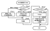
まず、SN01においては、表示制御基板80が採用しているゲームモード選択フラグの判別がなされ、選択フラグが「野球モード指定値」であった場合はSN02において野球モードのタイトル画面の表示がなされ、選択フラグが「サッカーモード指定値」であった場合はSN03においてサッカーモードのタイトル画面の表示がなされSN04に進みタイマT1の加算更新がなされる。ここで、ゲームモード選択フラグとは、表示制御基板80のRAMで記憶されており、いずれの演出を実行するかの判別に必要となるものであり、主に後述する演出選択等で光センサから出力される検出信号によって受付または変更されるものである。
【0131】
SN05では、タイマT1がタイムアップしたか否かの判別がなされる。タイマT1がタイムアップしていた場合は、SN06に進みタイマT1がリセットされ、SN07でデモ時プロセスフラグが演出選択案内プロセスフラグに更新され終了する。また、タイマT1がタイムアップしていなかった場合は、そのまま終了しSN02またはSN03のタイトル画面の表示をタイマT1がタイムアップするまで継続して表示される。
【0132】
次に、図26のSL03により実行される演出選択案内プロセス処理の処理内容を表示画面と併せて説明する。図29は演出選択案内プロセス処理の処理内容を示すフローチャートであり、図31は客待ちデモ時に行なわれる演出選択遊技画面の一例である。なお、説明上、演出選択案内プロセスと演出選択プロセスを分けて説明しているが、ひとつのプロセス処理として考えてもよい。
【0133】
まず、SP01においては、ガイド案内表示がなされる。ガイド案内表示とは、これから演出を変更可能となる演出選択画面へ移行することができる旨を案内するための表示をいう。図31(a)を参照して、たとえば、画面中に「フィーバースポーツ」と遊技機のネーミング表示がなされるとともに、現在のゲームモードは「野球編」であることを認識させるために同時に表示がなされる。また、この画面表示に併せて、サイドランプの点灯が激しくなり、スピーカーからも遊技音の発生が行なわれる。このように演出態様の変更の前段階として、予めその旨を報知する画面表示等がなされるため、複雑かつ斬新な演出選択であっても遊技者にとってわかり易いものとすることができる。また、遊技者が不在状態であってもかかる処理は行なわれるが、これにより、その他の遊技者の好奇心を高ぶらせることができる。
【0134】
続いて、SP02においては、ガイド表示選択受付画面が表示される。図31(b)を参照して、SP01のガイド案内に引き続きガイド表示として「演出変えるなら選んでね!」等がなされるとともに、「選択するよ!」等の選択対象とその内容の表示がなされ、「エントリータイムあと5秒」等の受付可能時間の表示等が行なわれる。また、サイドランプ・スピーカー音もこの画面表示に合わせて行なわれる。たとえば、エントリータイムのカウントダウンと同調させ点灯・音発生等が行なわれる。このように演出を変更するための選択の前段階として、演出変更画面への移行のための選択を設けていることにより、演出の変更を希望しない遊技者に誤って選択させてしまい遊技者の気に入っていた演出が変更されてしまうといった不都合の発生を防止することができる。
【0135】
SP03では、右側の光センサ62の判定が有効となるよう設定がなされる。これにより、演出等の選択が不可能であるにもかかわらず光センサの判定だけがなされるといった無駄な制御負担が行なわれることを回避することができる。この場合には左側の光センサ61の判定は無効となる。SP04では、センサ判定値として「10」が設定される。センサ判定値とは、センサが物体を検出するまでの所要時間であって、「10」である場合には33msec×10=0.33秒の間、センサが選択を検出するために必要であることとなる。
【0136】
SP05では、センサ判定処理が行なわれる。センサ判定処理とは、センサが物体を検出したか否かによってオン・オフフラグのセットを行なう処理であって、詳しくは図31を参照し後述する。次に、SP06では、右側の光センサ62のフラグがオンになっているか否か判別がなされる。オンフラグとなっていた場合にはSP07に進み選択受付音発生コマンド・ランプ点灯コマンドを音制御基板・ランプ制御基板に送信設定がなされ、SP08においてデモ時プロセスフラグを演出選択プロセスに更新が行なわれる。オンフラグとなっていなかった場合にはSP11に進みタイマT1の加算更新が行なわれ、SP12でタイマT1がタイムアップしたか否かの判別がなされる。タイムアップしていた場合にはSP13に進みデモ時プロセスフラグを停止図柄表示プロセスに更新が行なわれ、タイムアップしていなかった場合には演出選択案内プロセス処理を終了する。これにより、選択がなされなかった場合には演出選択遊技に進まず停止図柄表示画面が表示され、選択がなされた場合には演出選択遊技画面に移行することとなる。
【0137】
SP09では、右側の光センサ62の判定を無効となるように設定がなされ、SP10に進みタイマT1がリセットされ演出選択案内プロセス処理を終了する。
次に、図26のSL04により実行される演出選択プロセス処理の処理内容を表示画面と併せて説明する。図30は演出選択案内プロセス処理の処理内容を示すフローチャートである。
【0138】
まず、SQ01においては、演出選択画面表示がなされる。演出選択画面表示とは、演出態様を変更可能である時に表示される画面をいう。図31(c)を参照して、たとえば、選択可能な演出態様の内容が遊技者にとってわかりやすいように「サッカーモード」と「野球モード」の表示と、「エントリータイムあと5秒」等の受付可能時間の表示等が行なわれる。また、サイドランプ・スピーカー音もこの画面表示に合わせて点灯・音発生等が行なわれる。このように選択可能な演出態様の内容を画面表示,サイドランプの点灯パターン,遊技音等で表現し報知することにより、遊技者にとって演出選択遊技をわかりやすくできるとともに、選択画面自体の演出も多種多様に表現することが可能となる。なお、本実施形態においては、同時に「サッカーモード」と「野球モード」の表示を行なっているが、これに限らず、たとえば、「サッカーモード」と「野球モード」を交互に繰返し連続して演出態様を報知するようにしてもよい。これにより、報知パターンの幅が広がり遊技者の興趣が向上する。
【0139】
次に、SQ02においては、左右両方の光センサ61,62の判定が有効となるように設定がなされる。SQ03では、センサ判定値として「2」が設定される。よって、センサが物体を検出するまでの所要時間が33msec×2=0.066秒必要であることとなる。ここで、図29の演出選択案内プロセス処理のSP04で説明したように、ガイド表示選択受付画面の場合のセンサ検出所要時間が0.33秒であったのに対し、演出選択画面の場合のセンサ検出所要時間が0.066秒と5分の1の短い所要時間に設定していることが確認できる。これは、ガイド表示選択受付画面の場合は、パチンコ遊技機1の前面側に遊技者が座っていない場合であっても表示され光センサの判定が有効となるため、遊技台の前を通りすぎる人などを検出する誤検出を防止するために検出までの所要時間を比較的長く設定し、演出選択画面の場合は、遊技者により遊技が行なわれていることが明らかであるため、比較的短い所要時間で光センサの検出ができるように設定している。後述する選択遊技時のセンサの検出所要時間も同様に短く設定されている。これと併せて、前述した光センサの所定距離範囲を設定することにより、意識的に選択検出を行なっている場合以外の誤検出を排除し選択検出の精度をさらに高めることができる。
【0140】
SQ04では、選択フラグに左領域選択値=0を設定する処理がなされる。ここで選択フラグとは、光センサのオンフラグにもとづいて設定されるフラグであり、表示制御基板80は選択フラグの領域選択値と遊技制御基板31から伝送される変動パターンコマンドとの関係により演出に使う画像,ランプ点灯,遊技音等を設定する。よって、選択がなされず光センサからの検出信号が送られてこなければ、選択フラグは左領域選択値=0に決定され、左側の選択肢が予め定められた演出態様として決定されることとなる。これにより、選択がされなかったことでエラーを引き起こす危険性も無く、また、ランダムカウンタ等を用いて自動的に選択させる制御を新たに設ける必要も無く制御負担を格段に軽減させることができる。SQ04においては、センサ判定処理がなされる。
【0141】
SQ06では、左オフフラグがセットされているか否かの判別がなされる。セットされている場合はSQ07に進み左選択領域の表示をオフ表示動作させる処理がなされる。SQ08とSQ09においては、右側に関し同様の処理がなされる。
【0142】
SQ10では、左オンフラグがセットされているか否かの判別がなされる。セットされている場合にはSQ11に進み左選択領域の表示をオン表示動作させる処理がなされ、SQ12に進み選択フラグに左領域選択値=0を設定する。SQ13,SQ14,SQ15においては、右側に関し同様の処理がなされる。
【0143】
ここで、図31を参照してSQ04〜SQ15の処理を具体的に説明する。
図31(c)は、演出選択画面が表示された直後の画面表示である。SQ05により選択フラグとして左領域選択値=0が設定されているため、左側選択肢の「サッカーモード」が太枠で囲まれている。これにより、遊技者は現時点のままで選択を行なわなければゲームモードが「サッカーモード」に変更されることが予測できる。
【0144】
次に、図31(d)は、演出選択画面が表示された後に遊技者が右側選択肢の「野球モード」を選択した場合の画面表示である。これは、SQ04のセンサ判定処理において右オンフラグがセットされ、SQ13でSQ14に進み右選択領域の野球モード表示の外枠がオン表示動作することにより強調表示されている画面である。
【0145】
図31(e)は、受付時間残り2秒となったときに遊技者が再度左側選択肢の「サッカーモード」を選択した場合の画面表示である。これは、SQ08でSQ09に進み右選択領域の野球モード表示の外枠をオフ表示動作されることにより強調表示が終了し、SQ10でSQ11に進み左選択領域のサッカーモード表示の外枠がオン表示動作することにより強調表示されている画面である。このように、選択可能な受付時間を表示することにより光センサの検出可能期間がわかりやすくなり、選択されている選択肢の選択領域を強調表示することにより選択している選択肢が一目瞭然となり選択間違いを極力防止することができる。
【0146】
なお、検出可能期間として受付時間で遊技者に報知しているが、これに限らず、ローソクが燃え尽きていくような画像で報知し、選択できる間は火が付いているようにし、選択を受付けない場合は火が消えるような画像表示を行なってもよい。また、ランプ点滅間隔を終了に近づくにつれて短くする場合や、遊技音の発生量を終了に近づくにつれて小さくしていくように、画像表示と併せてランプ・遊技音で同時に報知するようにしてもよい。遊技者にとってさらに臨場感あふれる演出選択遊技を楽しむことができ興趣が増す。
【0147】
また、選択領域を強調表示することで選択されている選択肢を報知しているが、これに限らず、たとえば、「野球モード」ならばバットとヘルメットとボール等の野球を連想させる画像を画面背景に表示したり、野球の演出の一部を表示し報知するようにしてもよい。また、画像表示と併せてランプ・遊技音で報知するようにしてもよい。たとえば、「サッカーモード」が選択されている場合にはスピーカーから「サッカーです…サッカーです…サッカーです…」といった音声を発生させ報知するようにしてもよい。これにより、遊技者が選択しようとする演出態様の内容をより具体的にわかりやすく理解でき、選択後の演出が全く見当違いの演出になるといった遊技者の期待を裏切ることを極力防止することができる。
【0148】
次に、SQ16では、センサオン無効時間を設定する処理がなされる。これは、SQ04でオンフラグがセットされた後の所定期間はセンサを作動させず検出不可能とする時間であり、たとえば、無効時間が0.66秒に設定されている場合に、左オンフラグがセットされその後0.66秒経過するまでは、左側のセンサも右側のセンサも強制的に検出を行なえない処理がなされる。これにより、右側を選択検出直後、腕を下ろしてくる最中に左側が選択検出されるといった不都合を解消することができる。SQ17では、SQ16で設定された無効時間の加算更新が行なわれる。
【0149】
SQ18では、演出の選択受付(選択有効)タイマT1の加算更新がなされる。SQ19においては、タイマT1がタイムアップしているか否かの判別がなされる。タイムアップしていない場合は演出選択プロセス処理を終了するが、タイムアップしている場合はSQ20に進み選択フラグにもとづいて演出態様を設定する処理がなされる。SQ21においては、演出選択終了画面の表示がなされる。図31(f)を参照して、たとえば、画面中に「フィーバースポーツ」とパチンコ遊技機1のネーミング表示がなされるとともに、演出態様の変更選択がなされ、これから演出されるゲームモードは「サッカー編」であることを認識させるために同時に表示がなされる。
【0150】
SQ22では、デモ時プロセスフラグを停止図柄表示プロセスに更新する処理がなされる。SQ23では、選択フラグおよびT1をリセットする処理がなされる。最後に、SQ24において、左右両方の光センサの判定が無効となるように設定する処理がなされる。これにより、光センサを用いて遊技を行なうとき以外、すなわち、選択受付時間(有効期間)が終了した後は光センサの判定が無効となり無駄な制御を行なう必要がなくなり負担が軽減される。
【0151】
図32は、図29のSP05と図30のSQ04により実行されるセンサ判定処理の処理内容を説明する。図32はセンサ判定処理の処理内容を示すフローチャートである。
【0152】
SR01では、左センサチェック処理が行なわれる。すなわち、左側の光センサ61の検出が行なわれたか否かの判別が行なわれる。検出が行なわれている場合は、SR02において、左オフタイマと左オフフラグがクリアされ、左オンタイマが1加算更新される。次に、SR03で左オンタイマがセンサ判定値であるか判別がなされセンサ判定値(図29のSP04、図30のSQ03)である場合には左オンフラグがセットされ、SR04でセンサ判定値に達していなかった場合には左オンフラグがクリアされる。これは、あまりにも短いセンサ判定値に達しない期間の検出では左オンフラグはセットされず、演出の選択を行なうことができないように設定している。これにより、誤検出の防止をさらに高めることができる。SR05〜SR07は、SR02〜SR04で説明した内容とまったく逆の処理がなされ、センサ判定地に達しているか否かで左オフフラグのセットとクリアの処理が行なわれる。SR08〜SR14では、SR01〜SR07で説明した処理と同様の内容が右側の光センサ62に対して処理がなされる。
【0153】
図33は、大当たり処理において特典付与条件を満たしていた場合に遊技可能となる特別演出選択プロセス処理の処理内容を説明するためのフローチャートであり、図34は特別演出選択遊技の選択時の表示画面を示した図である。なお、その処理内容は、図30を用いて説明した演出選択プロセス処理と共通する部分の説明は省略する。
【0154】
ここで、特別演出選択遊技とは、特典付与条件が成立した場合のみ選択肢の中に特別な演出態様が含まれ、遊技者により特別な演出態様の選択が可能となる遊技である。通常は選択することができないため、遊技者にとって特別な演出態様の価値が高まり遊技の興趣が向上する。さらに、演出のパターン数が増えるため遊技の単調(マンネリ)化を防止することができる。
【0155】
次に、本実施形態の特典付与条件は、低確率時に前回の大当たりから今回の大当たりまでに要した可変表示回数が所定回数(たとえば、50回)未満であることを条件とする。これは、確変(高確率時)の助けを得ることなく、いわゆる自力で連続大当たりに近い大当たりを引き当てる必要があるため、易々と条件を成立させることは不可能であり、遊技者は苦心の末やっと特別な演出で遊技が行なうことができ遊技の興趣が向上する。なお、特典付与条件としては、これに限られず、たとえば、電源投入からの大当り回数が所定の回数を超えることを条件としてもよい。これにより、所定回数の大当りを発生させることにより、その大当りに付加価値が生じ遊技者の興趣が増す。なお、大当りとしては、第2種パチンコ遊技機(いわゆる、ヒコーキタイプ)における大当りでもよく、第3種パチンコ遊技機(いわゆる、権利物タイプ)における大当りでもよい。
【0156】
さらに、以上のような特典付与条件は、遊技機の公開されているデータから成立可能であるか否かがある程度判断できるものとなっている。これは、近年、遊技者が遊技台を選ぶ際に、その遊技台について公開されてある過去のデータを基準に選定する傾向が強いことに鑑み考え出したものである。このことから、遊技者にとっての台選びの基準が増え、遊技台に対する興趣を向上させることができる。なお、本実施形態においては、過去のデータ(たとえば、図柄変動回転数,大当り数,確変大当り数等)は公開されるだけでなく、遊技機の表示制御基板80によってもバックアップされており、このバックアップされたデータにもとづき、表示制御基板80により特別な演出態様を選択肢に含ませるか否かの判別が可能となる。また、特典付与条件として本実施形態ではふたつの条件について説明したが、これらに限られる必要はなく、その他の例は変形例として後述する。
【0157】
処理の内容について、まずST01において、特別演出選択画面表示の表示が行なわれる。ここでは、特典付与条件が成立しているため選択可能な演出の中に、成立時のみ選択可能となる特別な演出が含まれて表示されている。図34(a)を参照して、たとえば、特別な演出の選択肢として「オリンピックモード」が左側に表示され、普通の演出の選択肢として「野球モード」が右側に表示されている。また、サイドランプ・スピーカー音もこの画面表示に合わせて特別な点灯・特別な遊技音の発生が行なわれる。このように、自力連続大当たりを引き当て、その見返りとして、「オリンピックモード」の選択が可能となるため、「オリンピックモード」の特別な演出に対する価値が遊技者間の間で高まり遊技の興趣が向上する。また、前述したように、ゲームモードとして「サッカーモード」と「野球モード」に加え、特典付与条件成立時には「オリンピックモード」が選択可能となるため、演出のパターン数が増え遊技の単調(マンネリ)化を防止することができる。ST02〜ST18までの処理内容は、図30を用いて説明した演出選択プロセス処理のSQ02〜SQ18と共通するため説明を省略する。
【0158】
次に、ST19では、タイマT1がタイムアップしたか否かの判別がなされる。タイムアップしている場合はST20へ進み、選択フラグにもとづいて演出態様の設定がなされ、タイムアップしていなかった場合にはST05へ戻り、タイムアップするまで遊技者による選択を受付ける処理を行なわれる。ST21では、特別演出選択終了画面の表示が行なわれる。図34(b)を参照して、この画面表示は、特別な演出の選択肢としての「オリンピックモード」が選択され決定された場合の終了画面である。「オリンピック特別編」と表示がされ、これからゲームモードが「オリンピック特別編」に変更され演出がなされることを遊技者に報知している。ST22では、選択フラグおよびT1をリセットする処理がなされる。最後に、ST23において、左右両方の光センサの判定が無効となるように設定する処理がなされ特別演出選択プロセス処理は終了となる。
【0159】
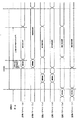
図35は、選択遊技実行可能な特定変動パターンを場合分けし、各変動パターンを構成するタイミングチャートの一例を説明するための図である。
【0160】
ここで選択遊技とは、遊技者に可変表示に関わる演出について選択を行なわせ、遊技者の選択が、表示される可変表示の表示結果に関与しているかのような演出を行なわせる遊技をいい、この実施の形態の場合は特別図柄表示部9への遊技画像の表示にもとづいて行なわれる。
【0161】
図35を参照して、選択遊技実行可能な特定変動パターンは通常の変動パターンと同様に変動開始コマンドを受信することにより変動パターンが実質的に開始される。この特定変動パターンのうち選択遊技開始時期によって3つに大別でき、(a),(b)についてはリーチ成立後に、(c),(d)については図柄変動中に、(e),(f)については全図柄の変動開始前に、それぞれ選択遊技とよばれる遊技が遊技者に提供される。また、この特定変動パターンのうち選択遊技中に行なわれる演出内容の変更状態により3つに大別でき、(a),(c),(e)については演出内容を一時的に変更、(b),(d)については演出内容の一部を変更、(f)については変動停止まで他の演出に差し替えがそれぞれ行なわれる。
【0162】
このような選択遊技は、表示制御基板80に設けられた表示制御用マイクロコンピュータにより実行される表示制御用のメインルーチンプログラムの実行に伴って実行される所定のサブルーチンプログラムの1つである選択遊技処理にもとづいて行なわれる。選択遊技処理の処理内容は図36を用いて詳細に後述する。
【0163】
なお、選択遊技実行可能な特定変動パターンを具体的に説明するために、一例を挙げたが、選択遊技処理の後は図柄の変動を行なわず選択遊技の演出結果で表示結果を表示する変動パターンであってもよく、逆に、選択遊技の演出結果で表示結果を表示させるものではなく選択遊技処理の後に再度図柄の変動を行ない表示結果を表示する変動パターンであってもよい。
【0164】
また、選択遊技開始時期により3つに大別したものに対し、それぞれに演出内容の変更状態により大別した3つの態様とのすべての組合せが考えられるものとする。たとえば、変動停止まで他の演出に差し替えが行なわれる場合は選択遊技開始時期が図柄変動前の(f)のみしか例を示していないが、選択遊技開始時期が図柄変動中・リーチ成立時の場合におこなわれる変動パターンであってもよい。このように変動パターンを複数種類備えることにより、遊技者が選択する機会,介入の機会が増加する。さらに、変動パターンが多彩となり遊技者の楽しみが向上する。
【0165】
さらに、図35には、1回の図柄変動中に1度の選択しか行なっていないが、選択遊技開始時期により3つに大別したものを組み合わせて図柄変動中に複数回選択遊技を行なうことができる変動パターンであってもよい。たとえば、1度目の選択が図柄変動開始前に行われ、その後、2度目の選択が図柄変動中あるいはリーチ成立時に行なうことができる変動パターンであってもよい。このように1回の変動中に複数回の選択遊技を行なうことで、複数回もの演出選択を行なったことが可能となり、可変表示装置8の表示結果に関与しているかのような演出が複数回行なわれることにより遊技者の興趣が向上する。さらに、当初の選択遊技が、再度選択遊技を行なえることをほのめかす予告機能として使用することができる。
【0166】
次に、変動パターンの一部として実行される選択遊技処理の処理内容を説明する。図36は表示制御用マイクロコンピュータにより実行される選択遊技処理の処理内容を示すフローチャートである。
【0167】
この選択遊技処理は、遊技制御基板31から選択遊技の実行を指令する表示制御コマンドが表示制御基板80に送られてきたことに応じて実行が開始される。この場合における選択遊技の実行を指令する表示制御コマンドは、たとえば、前述した変動開始コマンドである。なお、選択遊技の実行を指令する表示制御コマンドとしては、前述した変動パターンコマンド等その他の表示制御コマンドを用いてもよい。つまり、選択遊技開始のきっかけとなる表示制御コマンドであればどのようなコマンドを選択遊技の実行を指令する表示制御コマンドとして用いてもよい。また、選択遊技の実行を指令する表示制御コマンドとしては、選択遊技の実行開始のみを示す専用のコマンドを用いるようにしてもよい。
【0168】
まず、SU01により、選択遊技の開始と演出を選択することができる旨を案内するための選択遊技開始画面の表示が行なわれる。
【0169】
次に、SU02に進み、遊技者に複数の選択肢としてAとBの2つの選択肢を示して任意の選択を要求するガイド表示と選択画面を特別図柄表示部9に表示させる処理がなされる。この場合、表示制御用マイクロコンピュータ800は、左側の光センサ61が選択された場合に選択肢Aが選択され、右側の光センサ62が選択された場合に選択肢Bが選択されるように制御を行なう。
【0170】
次に、SU03に進み、左右両方の光センサ61,62の判定が有効となるように設定がなされる。SU03では、センサ判定値として「2」が設定される。前述したように、センサが物体を検出するまでの所要時間が33msec×2=0.066秒必要であることとなる。選択遊技画面の場合は、遊技者により遊技が行なわれていることが明らかであるためである。
【0171】
次に、SU05においては、選択フラグに左領域選択値=0を設定する処理がなされる。これにより、遊技者による選択がなされなかった場合に左側の選択肢が予め定められた演出態様として決定されることとなり、選択がされなかったことでエラーを引き起こす危険性も無く、また、ランダムカウンタ等を用いて自動的に選択させる制御を新たに設ける必要も無く制御負担を格段に軽減させることができる。次に、SU06に進み、センサ判定処理がなされる。
【0172】
SU07では、左オフフラグがセットされているか否かの判別がなされる。セットされている場合はSU08に進み左選択領域の表示をオフ表示動作させる処理がなされる。SU09とSU10においては、右側に関し同様の処理がなされる。
【0173】
SU11では、左オンフラグがセットされているか否かの判別がなされる。セットされている場合にはSU12に進み左選択領域の表示をオン表示動作させる処理がなされ、SU13に進み選択フラグに左領域選択値=0を設定する。SU14,SU15,SU16においては、右側に関し同様の処理がなされる。この際、図31(c)〜図31(e)を用いて説明した処理と同様の処理がなされることとなるため演出選択の場合と同様の作用効果を発揮させることができる。
【0174】
次に、SU17では、センサオン無効時間を設定する処理がなされる。SU18では、SU17で設定された無効時間の加算更新が行なわれる。これにより、選択した直後の誤検出を防止できる。SU19では、演出の選択受付(選択有効)タイマT1の加算更新がなされる。SU20においては、タイマT1がタイムアップしているか否かの判別がなされる。タイムアップしていない場合はSU27に進み、仮選択演出表示処理のサブルーチンが実行され、遊技者による操作に応じて選択したものに仮に決定された場合にどのように反映され演出が行なわれるのかを確認できる表示を行なわれる。仮選択演出表示処理は、SU20によりタイムアップしたと判断されるまでSU06〜SU20の処理が繰返し行なわれる。仮選択演出表示処理の詳しい処理内容については、図37を用いて後述する。また、タイムアップしている場合は、SU21に進み選択フラグにもとづいて演出態様を設定する処理がなされる。
【0175】
SU22においては、選択内容表示処理のサブルーチンが実行される。この演出内容表示処理では、選択フラグに対応した演出内容の表示を行なった後、SU23に進み、演出結果報知処理のサブルーチンが実行され、この処理では、前述したR1で抽出した値に従って決定されている可変表示の表示結果が特定の表示態様に制御されるのか否かを演出内容の進行と関連させた演出結果として報知する。いずれの処理についての詳しい内容は、それぞれ図38,図39を用いて後述する。
【0176】
そして、SU24に進み、選択遊技終了画面の表示がなされる。SU25において、選択フラグおよびT1をリセットする処理がなされる。この選択遊技処理に関連して使用した各種のフラグおよびタイマを初期状態に戻すために、これらをリセットする処理がなされる。最後に、SU26において、左右両方の光センサの判定が無効となるように設定する処理がなされる。
【0177】
なお、SU24における選択遊技終了画面としては、選択遊技を終了する旨を直接的に示す表示を行なってもよく、選択遊技の結果に関連する表示(たとえば、表示画面により「ホームラン」の映像が表示されることや、変更された「キャラクタ」が笑顔でダイヤモンドを回っている映像を表示することにより表示結果が特定の表示態様となる旨または再度の選択遊技実行可能となる旨の表示、または、表示画面により「空振り三振」の映像が表示されることや、変更された「キャラクタ」がうずくまり悔しがる映像を表示することにより表示結果が特定の表示態様とならない旨または再度の選択遊技はできない旨の表示を選択的に行なう等)を行なうことにより、選択遊技を終了する旨を間接的に示す表示を行なってもよい。
【0178】
次に、図36のSU27により実行される仮選択演出表示処理の処理内容を説明する。図37は、仮選択演出画面表示処理の処理内容を示すフローチャートである。
【0179】
まず、SV01において、選択フラグがオンになっているか、つまり、選択センサ61,62のいずれが選択検出されたか否かの判断がなされる。いずれの選択センサも検出されていない場合には演出画面の一部を表示する処理を行なうことなく仮選択演出表示処理の処理は終了し、いずれかの選択センサが選択検出されている場合にはSV02へ進む。
【0180】
SV02では、選択フラグに入力されている領域選択値の判別がなされる。検出されている領域選択値が「0」である場合は、SV03に進み、選択画面背景にA選択時の演出の一部を表示する処理を行なう。また、領域選択値が「1」である場合はSV04へ進み、選択画面背景にB選択時の演出の一部を表示する処理を行なう。それぞれの選択値に対応した演出内容の一部を表示する処理を行なう。
【0181】
かかる処理がなされることにより、遊技者が選択したことが選択結果として反映されていることを認識でき、選択通りに演出内容が変更されていることを視認しやすい。また、選択しようとする演出内容ではどのような演出が行なわれるのか遊技者は予想することができる。なお、かかる処理は、前述した受付期間内であれば選択する選択肢の変更ができることと同様に、再度いずれかの選択センサが検出されればその選択フラグにもとづく演出の一部を表示し、タイマT1がタイムアップするまで表示が行なわれる。また、前述した演出の一部とは、選択結果や演出内容の説明等を示すメッセージによる表示であってもよい。表示方法としては、選択時画面がみずらい等の悪影響を及ぼさないために選択画面の背景に透かして表示してもよく、加えて、選択した演出の特徴的な部分をトレース画像(たとえば、「カーブ」選択時にカーブの軌道,「打率200の右打者」選択時にキャラクタの態様を大根切り打法のスイングをしている態様に変化させる)の表示として何度も繰り返し表示してもよい。
【0182】
次に、図36のSU22により実行される演出内容表示処理の処理内容を説明する。図38は、演出内容表示処理の処理内容を示すフローチャートである。
【0183】
まず、SW01では、選択フラグに入力されている領域選択値を判別する。入力されている領域選択値が「0」である場合は、SW02に進み、表示画面にA選択時の演出内容を表示する処理を行なう。また、領域選択値が「1」である場合はSW03へ進み、表示画面にB選択時の演出内容を表示する処理を行なう。それぞれの選択値に対応した演出内容の一部を表示する処理を行なう。なお、変動パターンによっては、この演出内容表示処理を行なわないものがあってもよい。たとえば、選択遊技の一例としての「球種選択をしますか?」、「代打を送りますか?」に対しては、「YES」を選択すれば次のステップとしての球種選択や打者選択の選択遊技が行なわれる場合も考えられるからである。
【0184】
次に、図36のSU23により実行される演出結果報知処理の処理内容を説明する。図39は、演出結果報知処理の処理内容を示すフローチャートである。
【0185】
ステップSX01により、前述したR1から抽出したカウンタ値に基づいて決定されている大当りフラグが1であるか否かの判断がなされる。具体的に、SX01では、遊技制御基板31から送られて記憶された受信コマンドのうち、大当りフラグコマンドをチェックし、それにもとづいて、今回の表示結果が特定の表示態様となり得るか否かの判断がなされる。
【0186】
SX01において、大当りフラグコマンドにより表示結果が特定の表示態様となり得るか否か判断され、大当りとなる場合は、後述するSX02に進む。一方、SX01により、大当りとならない場合はSX05に進み、それぞれ前述した選択フラグがA,Bのいずれの領域選択値であるかが判断される。
【0187】
SX02により領域選択値が「0」であると判断された場合は、SX03に進み、特別図柄表示部9において、Aを選択したことが演出上有利となる演出結果の表示を行なう処理がなされて演出結果報知処理は終了する。一方、SX02により領域選択値が「1」であると判断された場合は、SX04に進み、特別図柄表示部9において、Bを選択したことが演出上有利となる演出結果の表示を行なう処理がなされて演出結果報知処理は終了する。
【0188】
SX05により領域選択値が「0」であると判断された場合は、SX06に進み、特別図柄表示部9において、Aを選択したことが演出上不利となる演出結果の表示を行なう処理がなされて演出結果報知処理は終了する。一方、SX05により領域選択値が「1」であると判断された場合は、SX07に進み、特別図柄表示部9において、Bを選択したことが演出上不利となる演出結果の表示を行なう処理がなされて演出結果報知処理は終了する。このように、可変表示の表示結果が大当たりとなるか否かに対応させて、遊技者により選択された演出を行なうことにより、遊技者の選択が大当たりに導いた、あるいは、はずれにさせてしまった等予想する楽しさが付加されることにより、遊技に対する興趣が向上する。
【0189】
なお、R1により遊技状態が特定遊技状態に制御され、可変表示の表示結果が特定の表示態様となることが決定している場合は、A,Bのいずれを選択した場合でも演出上有利となる演出結果の表示を行なう処理がなされ、R1により遊技状態が特定遊技状態に制御され、可変表示の表示結果が特定の表示態様とならないことが決定している場合は、A,Bのいずれを選択した場合でも演出上不利となる演出結果の表示を行なう処理がなされているがこれに限るものではない。遊技者による選択が、可変表示の表示結果に関与しているかのように思わせるような演出を行なうものであればよい。
【0190】
この点については、変動パターン中に複数の選択遊技可能な場合が考えられ、最終的な選択遊技の演出結果に従うからである。たとえば、9回1アウトランナー3塁の場面で「何を打ちますか?」の選択遊技では、最初の選択遊技で「カーブ」を選択し、その演出内容・結果が「カーブを打ちにいき、カーブを投げてこられたが外野フライに終わりアウト」となり、次の「3塁ランナータッチアップしますか?」の選択遊技で「タッチアップする」を選択しクロスプレーになりセーフで勝利になるといった変動パターンも考えられるからである。
【0191】
なお、変動パターンによっては、前述した演出結果報知処理の場合と同様、この演出結果報知処理を行なわない変動パターンがあってもよい。たとえば、選択遊技の一例としての「球種選択をしますか?」、「代打を送りますか?」に対しては、「YES」を選択すれば次のステップとしての球種選択や打者選択の選択遊技が行なわれる場合も考えられるからである。
【0192】
以上で、図36の選択遊技処理の説明を終了するが、図40,図41を用いて具体的に説明する。
【0193】
図40は、投手側から2種類の球種を選択する選択遊技を行なう変動パターンの場合のフローチャートである。図41は、その選択遊技の画面表示の一例を示した図である。なお、ゲームモードとして、演出選択遊技において「野球編」が選択された場合を想定して、以下選択遊技の画面表示等の説明を行なう。
【0194】
まず、変動パターンが前述した図35に示す特定変動パターンのうちのいずれかであった場合に、図柄変動前,図柄変動中,リーチ成立時に選択遊技が開始される旨を報知する選択遊技開始画面の表示がなされる。図41(a)を参照して、たとえば、「球種を選択しましょう!」といったこれから演出の選択を受付可能となる旨を案内するガイド報知が実行される。同時に、演出選択の判断基準ともなるゲームモードの状況等を説明する表示がなされる。
【0195】
次に、図41(b)に示されるような選択画面が表示され、遊技者に対して球種の選択が要求される。
【0196】
具体的に、この選択画面では、光センサ61により選択可能な選択肢としての「カーブ」と光センサ62により選択可能な選択肢としての「直球」とが並んで表示され、「何を投げますか?」という文字表示により、遊技者に対して「カーブ」を投げるか「直球」を投げるかの選択が要求される。また、この選択画面では、「エントリータイム残り5秒」と示されるように選択を受付ける前述の受付時間の残り時間が示される。これにより、いつまでに選択すればよいかを遊技者にとって容易に把握することができるようになる。
【0197】
そして、エントリータイム内に遊技者が選択すれば、図41(c),(d)に示されるようなそれぞれの選択肢に対応した選択時画面が表示され、遊技者に対して選択していることが示される。具体的に、エントリータイム内に光センサ61による選択が行なわれて「直球」が選択された場合には、「直球」の選択時画面に切り替わり、選択された選択肢である「直球」が強調表示され、選択されなかった「カーブ」はそのままの状態で表示される。つまり、選択された「直球」が選択されなかった「カーブ」よりも目立つように表示(たとえば、色彩の変更,文字の大きさを変更等)されることにより選択が行なわれている旨が示されるのである。
【0198】
さらに、選択された選択肢である「直球」が強調表示されると同時に、「直球」を選択した場合の演出内容の一部である「直球」の軌道(図41(d))が選択画面背景に重ねて表示され、ボールが直球の軌道に沿って投げられている映像が繰り返し行なわれる。「カーブ」を選択した場合は図41(c)のような「カーブ」の軌道が選択画面背景に重ねて表示される。これにより、選択したことがどのように反映されるのか確認でき、また、どのような演出が始まるのかその演出態様の内容のうち一部の表示を見ることができ、選択する際に参考とすることができる。なお、ボールの軌道表示に加えて、投げている投手に「俺のカーブが打てるかな?」等のコメントや、「カーブ」を選択すると投手であるキャラクタが炎に包まれている映像のようにキャラクタを変化させることを加えてもよい。キャラクタは無数に変化させることができるため、選択の基準として参考にできる補助表示のパターンを多数設定することができ、遊技者の興趣が増す。
【0199】
また、始めに選択された選択肢が「直球」であっても、エントリータイム内であれば何度でも選択を行なうことが可能であり、「直球」の演出内容の一部である軌道を見て「カーブ」の選択肢に変更する再選択が可能である。これにより、選択間違いによるトラブルを防止することができ、加えて、遊技者はすべての選択肢に対する演出内容の一部を確認し納得して一方を選択することができる。
なお、エントリータイム内に遊技者が何ら選択を行なわなかった場合は、前述したように左領域選択値=「0」が決定され、A選択時画面が表示される。たとえば、未選択状態であった場合は、「カーブ」を選択することがデフォルトとしてあらかじめ決められている。このように前もって未選択時に選択される枝が決まっていることでエラーとなることを回避でき、設計上においても自動抽選等の複雑な処理を省くことができる。
【0200】
その後、選択画面の表示開始時から前述したタイマT1が終了すると、選択時画面の表示が終了し、演出内容表示画面が行なわれる。具体的には、選択画面で「直球」を選択していた場合に投手は必ず「直球」を投げる演出内容を表示し、同様に、選択画面で「カーブ」を選択していた場合に投手は必ず「カーブ」を投げる演出内容を表示する。すなわち、演出内容表示画面では、遊技者が選択した「カーブ」または「直球」を投手に投げさせ、演出内容を一時的に変更させている。なお、加えて、前述したものに対応させて、「打ってみろ!」といった雄叫びを上げるような「コメント」の表示や炎に包まれているキャラクタが投球をしている表示をあわせて行なってもよい。そして、投手により投げられた球を打者が打つ直前までが演出内容表示画面として演出される。
【0201】
次に、演出結果報知画面の表示が行なわれる。R1により判定され事前に決定されている大当りフラグコマンドが1である場合は、選択した選択肢が演出上有利となる演出結果を表示する。これとは逆に、大当りフラグコマンドが0である場合は、選択した選択肢が演出上不利となる演出結果を表示する。具体的に、大当りに制御する場合は、選択画面にて「カーブ」または「直球」のどちらを選択した場合においても、打者は「空振り三振」,投手は「ガッツポーズ」等となり、演出上勝利につながる有利な演出結果を報知する表示が行なわれる。これとは逆に、大当りに制御されない場合は、選択画面にて「カーブ」または「直球」のどちらを選択した場合においても、打者は「ホームラン」,投手は「マウンドにひざまずく」等となり、演出上敗北につながる不利な演出結果を報知する表示が行なわれる。
【0202】
以上のように、演出内容表示画面で演出が行なわれる際に遊技者の選択した演出を行なうために演出内容を一時的に変更(カーブか直球か)させたことが、可変表示の表示結果に関与しているかのような演出を演出結果報知画面で行なわれる(三振かホームランか)ため、その演出を見ることにより遊技者の興趣を向上させる。
【0203】
その後、選択遊技の終了を報知する選択遊技終了画面が表示され、選択遊技は終了する旨が示される。たとえば、「完封勝利」、「辛くも逃げ切り勝利」等の表示とともに、遊技者が扮する表示態様が変更されたままのキャラクタである投手(たとえば、炎に包まれているキャラクタ)とチームメートが喜んでいる画像を表示する。
【0204】
次に、この実施の形態により得られる主な効果をまとめて説明する。
前述した演出選択遊技・選択遊技の場合、一定条件を満足することにより、遊技者からの選択指示にもとづいて、演出態様等を変更することができる。これにより、常に同じ演出態様で遊技が進行する受身遊技ではなく、遊技者自ら希望する演出態様に決定することができるため、遊技演出に飽きが生じず遊技の興趣を向上することができる。
【0205】
前述したように受付時間内(有効期間内)であれば遊技者による選択が可能であり、さらに、一度選択をしてしまった場合であっても、受付時間内であれば、その選択の内容を変更するための再度の選択をすることができる。これにより、選択操作ミスや光センサによる誤検出を事後的に補完することができ、せっかくの演出態様変更のチャンスを逃してしまうといった不都合を防止することができる。
【0206】
前述したように客待ちデモ表示がなされている待機状態においても、演出態様を変更するための受付期間が設定されており、遊技者の選択により演出の変更を行なうことができる。これにより、待機状態であるにもかかわらず、その画面表示を見た遊技者の興味を引きつけ好奇心を高ぶらせることができる。
【0207】
前述したように受付期間終了をタイマT1がタイムアップしたか否かにより判定している。これにより、受付期間が継続しつづけるといった無駄な制御負担の軽減を図ることができる。
【0208】
前述したように受付期間内において選択可能な演出態様が表示される際に、その演出態様の内容(どのような演出が行なわれるのか)が遊技者にとってわかるように画面表示・ランプ点灯・遊技音等を駆使して報知がなされる。これにより、変更可能な演出態様がわかりやすいだけでなく、その演出態様の内容も把握することができ遊技者の期待を裏切る演出が行なわれる不都合の発生を防止することができる。
【0209】
前述したように遊技者による選択が行なわれた場合に、選択がなされていることを遊技者にとってわかるように報知を行なっている。これにより、選択が確実に行なわれていることが遊技者にとってわかりやすく、さらに、非接触により検出可能であるがために発生する欠点、すなわち、物理的感触により選択の確認を行なうことができないため検出できているのか否か不安になるといった欠点を補うばかりでなく、視覚・聴覚を通して遊技者に認識させることが可能となる。
【0210】
前述したように選択可能な有効期間中である旨の表示を行なうことができる。これにより、選択可能な期間が遊技者にとってわかりやすく、あせって誤検出させてしまう等の不都合を回避することができる。
【0211】
前述したように光センサ61,62から伝送される検出信号は、表示制御基板80にすべて入力され、その信号にもとづき表示制御基板80から音制御基板70・ランプ制御基板35にコマンドを出力している。これにより、遊技演出中に画像表示と遊技音またはランプ点灯パターンが微妙にずれる不都合を解消でき、常に同期のとれた演出を遊技者に提供することができる。
【0212】
前述したように大当り遊技状態に関連して、たとえば、大当り遊技終了後に、演出態様を変更する機会を設けている。これにより、遊技者にとって大当りになれば演出態様を変更することができると認識させることができ、変更可能な契機をわかりやすくすることができる。
【0213】
前述したように演出態様を変更するための手段として光センサを使用しているため、遊技者が遊技機に非接触で選択検出を行なうことができる。これにより、物理的なスイッチ(たとえば、押しボタンスイッチ)のように遊技者に接触する態様で選択に関する信号入力を行なう接触入力手段を用いる場合と比較して、装置が物理的に破損するおそれが少なくなる。
【0214】
さらに、選択センサのような非接触入力手段を遊技領域に設けたことにより、遊技機の枠を共通化することができる。これにより、遊技機の機種変更を行なう場合には遊技盤を新しいものに交換するに際して遊技枠ごと新しいものに交換せずに遊技盤のみを交換することで足りるようにすることができる。
【0215】
前述したように選択遊技は遊技者により演出を選択したことが、可変表示の表示結果に関与しているかのような演出を行なうことができる。これにより、たとえば、「カーブ」を選択し可変表示の表示結果が「777」である場合には、「カーブ」を投げてバッターを三振にとる演出を行なうことができ、その演出により遊技者は「カーブ」を選択したことが正解だったと思わせ、遊技者の遊技に対する興趣が増す。逆に、「直球」を選択し可変表示の表示結果が「556」である場合には、「直球」をなげてホームランを打たれる演出を行なうことができ、その演出により遊技者は「直球」を選択したことが失敗だったと思い、次回の対抗策などを練る楽しみが増え興趣が向上する。
【0216】
前述したように遊技者により遊技が行なわれている蓋然性が低い演出選択案内画面時の光センサの検出時間は、遊技者により遊技が行なわれている蓋然性が高い演出選択画面時や選択遊技画面時の光センサ検出時間の5倍長く設定されている。これにより、遊技者不在時などに遊技機前を通りすぎる客などを検出してしまうことが起こり得ず、誤検出を防止することができる。
【0217】
前述したように受付期間内に遊技者からの選択がなかった場合に演出態様を予め定められた演出に決定している。これにより、未選択によるエラーの発生を防止するとともに、未選択時に備えて新たにランダムカウンタ等を設ける必要が無く制御負担を軽減することができる。
【0218】
前述したように特典付与条件成立時にのみ特別な演出態様を選択可能にしている。これにより、同じゲームモードの中からの選択しかできない場合と比較し、遊技の単調(マンネリ)化を防止することができ、遊技に飽きがこず興趣向上につながる。また、遊技者の特別な演出態様で遊技してみたいと思う願望が強まり、遊技に集中しさらに興趣を増すことができる。
【0219】
また、特典付与条件として、低確率時に前回の大当りから所定の変動回数未満で今回大当りすることを一例として示した。これにより、大当り遊技を行なう楽しみに加えその後は、特別な演出態様で遊技が可能となる付加価値が生じ遊技者の自力大当りへの期待度を向上させることができる。
【0220】
前述したように選択の受付をする以前に、選択について案内・説明ためのガイド報知が行なわれている。これにより、演出態様の変更にかかわる選択をさせる前に、予めガイド報知が行なわれるので、遊技者にとって演出選択遊技等の進行をわかりやすいものとすることができる。
【0221】
また、ガイド報知中に、演出態様を選択することができる演出選択遊技へ移行させるか否かの選択を行なっているため、突然、わけもわからぬまま演出態様が変更されてしまうという不都合を未然に防止することができる。
【0222】
前述したように光センサと可変表示装置に表示される選択肢はそれぞれ対応しており、さらに、可変表示装置を正面視した場合に、光センサの有効検出範囲と表示される選択対象物の外縁とが重畳するように光センサを設けている。これにより、可変表示装置の表示と目視できない光センサの有効検出範囲が互いにリンクさせることができ、選択時において簡単に選択を行なうことができる。
【0223】
前述したように光センサとして物体までの距離を測定しその距離が所定距離範囲内にあるか否かで物体の有無の判別を行なう測距式センサを用いた。これにより、受光量で物体の有無の判別を行なう光量式センサと比較した場合に、反射率に影響を受けにくいため、検出の信頼度を向上させることができる。
【0224】
前述したように透過部材の性質を考慮し、センサの反射率・検出距離範囲・設置箇所を調節設定することで、透過部材により反射した光路上の遊技機部品が設置された範囲以外で、かつ、所定距離範囲内の物体を検出可能にした。これにより、透過部材により反射した光路上に存在する物体以外の検出距離範囲に存在する物体を検出できるため、遊技機部品を検出してしまう不都合を防止することができる。
【0225】
第2実施形態
次に、第2実施形態を説明する。前述した第1実施形態では、演出選択または選択遊技のそれぞれにおいて2択の遊技例を示したが、この第2実施形態においては、光センサ61、62に加え、第3の光センサ63を可変表示装置8の下部に取りつけ、3択の演出選択または選択遊技のそれぞれにおいて説明する。
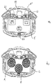
図42は、本実施形態で用いる可変表示装置8’と光センサ61,62,63それぞれの有効検出範囲を示した図である。なお、図1に示された可変表示装置8と共通する部分については同一の参照番号を付し、その説明を省略する。
【0226】
図42(a)は、本実施形態で用いる可変表示装置8’と演出選択遊技画面を示した図である。可変表示装置8’においては、遊技者により画面表示上の左側の選択肢(たとえば、「テニスモード」の選択肢)の選択を検出するための第1の光センサ61を特別図柄表示部9’の左上部に設け、遊技者により画面表示上の右側の選択肢(たとえば、「野球モード」の選択肢)の選択を検出するための第2の光センサ62を特別図柄表示部9’の右上部に設けている。さらに、本実施形態においては、可変表示装置8の下部中央に、遊技者により画面表示上の中央に表示されている選択肢(たとえば、「選択決定」ボタン表示)の選択を検出するための第3の光センサ63が設けられている。
【0227】
図42(b)は、演出選択時に光センサ61,62,63の判定が有効になった場合のガラス板2’前面における有効検出範囲と選択肢の関係を説明するための図である。図中のA,B,Cは、光センサ61,62,63それぞれの有効検出範囲を示している。
【0228】
本実施形態においても、第1実施形態と同様に、遊技者が演出選択画面の表示を見た場合に、特別図柄表示部9’に表示される選択肢と光センサ61,62,63の有効検出範囲が互いに重なり合うようにそれぞれ設定されている。これにより、遊技者は、選択したい選択肢の表示を押すような感覚でガラス前面に指を移動させるだけで、目視することはできない光センサの有効検出範囲に指を自動的に移動させることができ、選択肢の数が3つになっても容易に光センサに検出させ、遊技者が選択を望む選択肢を選択可能となるため迅速に遊技を進行させることができ、遊技に対する興趣が向上する。
【0229】
また、選択肢それぞれに対応した光センサが設けられているため、選択対象となる選択肢を多様に表示させた場合であっても、一回の選択作業で選択を行なうことができる。これにより、選択操作が簡単に行なうことができるとともに、複数の演出態様を画面に表示することで表示画面をインパクトのあるものとすることができる。
【0230】
さらに、複数の光センサを設けた場合であっても、第1実施形態で説明したように、その所定距離範囲や設置位置・角度を調整することによりそれぞれの光センサの有効検出範囲が重ならないよう設置することができる。これにより、遊技者が左側の選択肢(たとえば、「テニスモード」の選択肢)を選択した際に、中央の選択肢(たとえば、「選択決定」ボタン表示)も検出してしまう等の誤検出を未然に防止することができる。
【0231】
なお、光センサ63は、打玉の流下経路中に設置されるため、その打玉を検出するのではとの疑問があるが、これについては、打玉は反射率が高く遊技者の指までの距離より確実に短いため、前述したように、光センサの反射率を人の肌の反射率(約40パーセント)前後に設定することで打玉を検出することはなく、さらに、所定距離範囲をガラス板2’前面から前面側に5cm程度に設定することで誤検出防止に万全を期すことができる。
【0232】
なお、光センサの配置に関して、本実施形態では、逆三角形状に光センサを配置しているがこれに限らず、順三角形状でもよく、また、全く不規則な配置にしてもよい。また、光センサの数を3つに限る必要もなく、4つ以上であってもよい。画面に表示された選択肢に対応するように光センサが配置されてあればよい。
【0233】
図43は、本実施形態における演出選択遊技画面の一例である。なお、第1実施形態では、客待ちデモ時の所定期間に行われる演出選択遊技について特に詳しく説明したが、本実施形態において説明する演出選択遊技は、図25のSK08で行なわれる大当り終了時の演出選択プロセス処理を想定して説明する。また、演出選択遊技において、演出選択案内遊技を行なった後に演出選択遊技を行なうようにしてもよい。遊技者にとってよりわかりやすい遊技にすることができる。
【0234】
図43(a)は、演出選択開始画面を示す図である。画面中に「大当り終わり」と遊技状態を知らせる表示がなされるとともに、大当り前のゲームモードが「野球編」であったことを認識させるために同時に表示がなされる。また、この画面表示に併せて、サイドランプの点灯が激しくなり、スピーカーからも遊技音の発生が行なわれる。このように演出態様の変更の前段階として、このような画面表示等がなされるため、大当り遊技から演出選択遊技に移行がなされたことを遊技者にとってわかり易く明確になる。
【0235】
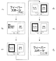
図43(b)は、演出選択画面を示す図である。選択可能な演出態様の内容が遊技者にとってわかりやすいように「テニスモード」と「野球モード」の表示が行なわれる。これにより、たとえば、「テニスモード」を選択すれば、「テニス」の演出がなされるのであることが予測できる。
【0236】
また本実施形態においては、さらに、それぞれの選択肢表示領域の下にその演出態様を選択することでどのような演出が行なわれるのか、より具体的に予測をつけることができるような表示がなされている。すなわち、「テニスモード」の下には、「4大会制覇を目指すならテニスだ!」とのコメントが表示されている。これにより、遊技者は、「制覇」を「大当り」に、「目指す」を「狙う」を意味しているのだろうと受け止めることができ、4回大当りを狙うのであれば「テニスモード」だな、と、予測することができる。
【0237】
仮に、この「テニスモード」を選択すると、この演出選択遊技以降の初めての大当りまでがアメリカを舞台に繰り広げられるテニスの試合を演出として使い、初当り後から2回目の大当りまでがイギリスを舞台に繰り広げられるように構成し、同様に大当りにより舞台を変える演出が行なわれ、4回目の大当り終了後に、4大会制覇の見返りとして、前述した特典付与条件を成立させ、新たに特別演出選択遊技を遊技者に与えるように構成してもよい。大当りするごとに関連性のある演出に変更されるので飽きがこず、物語性を楽しむことができる。同様に「野球モード」についても、「首位打者」「打点王」「本塁打王」をめざす大当り3回にわたり繰り広げられる演出であることを遊技者に報知している。 このように、演出態様の内容が把握できる表示を行なうことにより、遊技者が選択する際の基準とすることができ演出選択遊技に対する興趣が増す。
【0238】
また、画面中央には、選択肢に向かって矢印の表示がなされている。これは、第1実施形態でも説明した選択肢を強調表示することに加えて、さらに、現在選択がなされている選択肢を矢印により報知している。これにより、矢印の表示を見るだけで現在どちらが選択されているのかということが容易に確認でき、選択ミスによる誤検出の発生を防止することができる。
【0239】
また、演出選択遊技が開始される以前のゲームモードが「野球編」であったのに対し、左の選択肢に「テニスモード」と右の選択肢には「野球モード」の表示がなされている。これは、遊技者が選択を行なわなかった場合に、前述した図30のSQ04において選択フラグに左領域選択値=0の設定がなされるため、強制的にゲームモードが「テニスモード」に切換わるように設定されている。これにより、演出選択遊技が行なわれるたびに異なるゲームモードに切換わるため、飽きが生じ難く興趣が向上する。また、制御負担の軽減がなされている。
【0240】
また、遊技者が「野球モード」を気に入っていた場合には、遊技者の選択により、「野球モード」の演出に決定され、同じ演出態様で遊技を行なうことができる。これにより、複数種類の演出態様の中でも遊技者の気に入っている演出態様で遊技を行なうことができ興趣が向上する。
【0241】
さらに、図43(b)には、画面表示中央部に「選択決定」のコメント表示がなされた選択肢の表示がなされている。これは、遊技者が、受付期間終了前に早々と現在選択している選択肢で決定する場合に検出させる選択肢である。よって、「残りタイム5秒」の表示がなされている場合であっても、遊技者が「選択決定」の選択肢を選択することで受付期間は終了し、演出態様が決定される。これにより、受付期間の終了を待つまでもなく、選択決定を行なうことができるため、受付期間を継続しつづける必要がなくなり、図31のSQ19の判別により繰返し実行される制御処理を、選択決定後は行なう必要がなくなり制御負担の軽減が図れる。
【0242】
図43(c)は、「野球モード」の選択肢が遊技者により選択された場合の表示画面である。図43(b)と比較し、「野球モード」の選択肢が強調表示され、「テニスモード」の選択肢は通常の特に目立たない表示に変化している。また、矢印の向きも「テニスモード」から「野球モード」の方向に表示画像が変化している。なお、このような表示画像の変化に加えて、演出選択遊技画面の背景に、三冠王を連想させるバットを持った野球選手を表示するようにしてもよい。これにより、変更されたことがより明確に遊技者に報知することができる。また、その選択肢による演出内容をある程度予測することができる。
【0243】
図43(d)は、図43(c)の選択状態で残りタイムが終了したか、または、遊技者により「選択決定」の選択肢が選択され、「野球モード」に演出態様が決定した場合の演出選択遊技終了画面である。この表示により、遊技者は今後のゲームモードは「野球編」で演出が行なわれることと、演出選択遊技が終了したことを確認でき、遊技者にとってわかりやすく遊技を進めることができる。
【0244】
続いて、図44,図45を用いて、前述したゲームモードが「野球編」の場合の選択遊技について説明する。
図44は、攻撃側から代打を選択する選択遊技を行なう変動パターンの場合のフローチャートである。図45は、選択遊技画面の一例を示した図である。
【0245】
選択遊技が開始されると、まず、図45(a)に示されるような選択遊技開始画面(「代打をしましょう!」という文字により選択遊技が開始される旨が示される)が表示され、選択遊技が開始される旨が報知される。そして、図45(b)に示されるような選択画面が表示される。
【0246】
具体的に、図45(b)の選択画面では、「打率385の右打者」と「打率200の右打者」「打率800の左打者」とが逆三角形状に配置表示されている。選択に際しては、遊技者は画面上の各打者の表示に指を触れるような感覚でガラス板2’前面に指を移動することにより、各打者を選択することができる。これは、前述したように、画面上の選択肢表示の外縁が、該選択肢に対応する光センサの有効検出範囲に含まれるように互いに調節設定しているためである。このように、選択肢の表示位置と光センサの検出範囲をリンクさせているため、光センサの有効検出範囲がわからなくても、遊技者は容易に選択を行なうことができる。
【0247】
選択が行なわれると、選択された打者の打率が選択画面上に表示され、選択が行なわれたことを報知している(図45(c),(d))。これにより、遊技者が選択している打者が認識でき、その報知情報によりその打者の能力も同時に把握することができる。また、エントリータイム内であれば、何度でも再選択ができるため、その報知情報をもとに再度選択することもでき納得して選択を行なうことができる。
【0248】
また、打率情報に加えて、選択された打者にアクションやコメントの表示を演出内容の一部として表示してもよい。たとえば、大根切り打法のような「独特のスイング」をさせキャラクタの表示態様に変化をつけたアクション表示や意気込み・調子を表現する「ボールが止まって見える!」等のコメントである。このように、打者情報について打率のみならずアクションやコメントを演出内容の一部として表示することにより遊技者が選択する基準条件が増え遊技者の興趣は増し、納得して選択をすることができる。
【0249】
なお、エントリータイム内に遊技者が何ら選択を行なわなかった場合は、前述したような選択フラグにもとづいて、左領域選択値(0)に対応した左側の打者が強制的に選択される。このように前もって未選択時に選択される選択肢が決まっていることでエラー発生を回避でき、設計上においても自動抽選等の複雑な処理を省くことができる。
【0250】
その後、選択画面の表示開始時から前述したタイマT1が終了すると、選択時画面の表示が終了し、演出内容表示画面が行なわれる。具体的には、選択画面で「打率200の右打者」を選択していた場合には、代打として「打率200の右打者」が打席に送られる演出内容を表示し、同様に、選択画面で「打率800の左打者」を選択していた場合にも、代打として「打率800の左打者」が打席に送られる演出内容を表示する。「打率385の右打者」を選択した場合も同様である。すなわち、演出内容表示画面では、遊技者が選択した「打率200の右打者」または「打率800の左打者」「打率385の右打者」を打席に立たせ、選択以後の演出内容の一部を変更させている。これにより、遊技者が選択した打者を代打に送ったことが関与して、可変表示に表示される結果なったような印象を与え、遊技者の遊技を積極的に進めようとし興趣が増す。
【0251】
なお、タイマT1が終了する前に、選択している選択肢をもう一度検出させた場合に、選択の決定がなされるようにしてもよい。たとえば、「打率385の右打者」の選択がなされており残りタイムが2秒ある場合であっても、遊技者がもう一度「打率385の右打者」の選択を行なうことで、「打率385の右打者」の選択肢を選択結果として決定してもよい。これにより、前述したとおり、制御負担の軽減が図れる。また、残りタイム中に、操作ミスが発生し誤検出されてしまう等の不都合を未然に防止することができる。
【0252】
また、選択肢の中に「打率800の左打者」が含まれている。このような、特に打ちそうな選択肢、すなわち、大当り演出が行なわれる確率が高いように思える選択肢を、前述した特典付与条件成立時のみ出現させるようにしてもよい。選択肢のパターンを複数設定することができ、遊技の単調(マンネリ)化を防止することができる。
【0253】
次に、演出結果報知画面の表示が行なわれる。R1により判定され事前に決定されている大当りフラグコマンドが1である場合は、選択した選択肢が演出上有利となる演出結果を表示する。これとは逆に、大当りフラグコマンドが0である場合は、選択した選択肢が演出上不利となる演出結果を表示する。具体的に、大当りに制御する場合は、選択画面にて「打率385の右打者」と「打率200の右打者」「打率800の左打者」のいずれを選択した場合においても、打者が打席に立ち「ホームラン」となり、演出上勝利につながる有利な演出結果を報知する表示が行なわれる。これとは逆に、大当りに制御されない場合は、選択画面にて「打率385の右打者」と「打率200の右打者」「打率800の左打者」のいずれを選択した場合においても、打者が打席に立ち「空振り三振」となり、演出上敗北につながる不利な演出結果を報知する表示が行なわれる。
【0254】
その後、選択遊技の終了を報知する選択遊技終了画面が表示され、選択遊技を終了する旨が示される。たとえば、「接戦ものにし勝利」や確率変動状態で連続3回目の大当りの場合は「3試合連続サヨナラ勝ち」等の表示とともに、遊技者扮する監督と打者を含むチームメートが握手している画像を表示する。
【0255】
以上のように、遊技者の選択した演出が行なわれるが、その選択肢を選んだことにより、大当りになったり、はずれになったりしているように思わせる演出が演出内容表示画面と演出結果報知画面で行なわれる。これにより、選択する際に策を練ったり、パターンを予想したりできる楽しみが生じ、遊技者の興趣を向上させることができる。
【0256】
次に、この実施の形態により得られる主な効果をまとめて説明する。
前述したように、遊技者による選択肢の選択がなされなかった場合には、受付期間開始時の演出態様とは異なる演出態様に強制的に変更となる(図30のSQ04において選択フラグに左領域選択値=0の設定がなされるため)実施を説明した。これにより、演出選択遊技や選択遊技に無関心な遊技者にとっても、複数の演出(たとえば、「野球編」,「サッカー編」,「テニス編」)で遊技を楽しむことができ、演出を多様に変化させることが可能となり興趣が向上する。
【0257】
基本的に、演出選択遊技も選択遊技も選択可能な受付期間を設定してあり、その期間内に遊技者が選択を行なえ、受付期間終了によりその選択が決定されるように構成されているが、前述したように、「選択決定」の選択肢を選択することや、同じ物を連続して2度選択することにより受付期間終了を待たずにその選択が決定される(遊技者選択決定手段)ように構成された実施についても説明した。これにより、遊技者が自主的に選択を決定することができ、遊技に介入している感覚が高まり興趣が向上する。また、受付時間終了までの制御を負担することができる。
【0258】
前述したように、演出選択遊技のみならず選択遊技においても、特典付与条件成立時に特別な演出(「打率800の左打者」)を選択できる実施を説明した。このように、大当り演出が行なわれる確率が特に高いように思える選択肢を特典付与条件成立時のみ出現させるようにしたことにより、選択肢のパターンを複数設定することができ、遊技の単調(マンネリ)化を防止することができる。
【0259】
また、以上に示した第2実施形態については、前述した第1実施形態と共通する技術思想による構成について、前述した第1実施形態の場合と同様の技術的効果を得ることができる。
【0260】
第3実施形態
次に、第3実施形態を説明する。前述した実施形態では、遊技制御基板31から伝送される指令信号は、表示制御基板80にすべて入力され、その指令信号と演出に用いるゲームモードと光センサから送信されてくる検出信号にもとづき、表示制御基板80において音制御コマンド・ランプ制御コマンドが設定され、それぞれ音制御基板70とランプ制御基板35にコマンドを伝送し、各機器を制御する回路構成を説明した。
【0261】
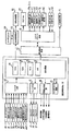
図46は、本実施形態で用いる回路構成を示すブロック図である。なお、図4に示された回路と共通する部分については同一の参照番号を付し、その説明を省略する。
【0262】
本実施形態においては、図46を参照し、遊技制御基板31から演出制御基板81に各種指令信号が伝送され入出力ドライバ基板82を経て各機器を制御する回路構成について説明する。なお、以下説明する本実施形態での効果は、前述した第1実施形態・第2実施形態の遊技に関し直接効果を発揮するものであり、特に、演出選択遊技等の場合には、光センサの検出とそれにもとづく報知情報(画面表示、遊技音、ランプ点灯)が常に同調している状態で遊技を楽しむことができ、興趣を向上させることができる。
【0263】
図46において、図4の回路構成との決定的な相違点は、図4に示す表示制御基板80と音制御基板70とランプ制御基板35の遊技演出を制御する基板が、図46に示す演出制御基板81にまとめられていることである。
【0264】
このように演出に関する基板を一つの基板にまとめたことにより、たとえば、表示制御基板80から音制御基板70,ランプ制御基板35に送信されてきたコマンド受信時に際してエラーが発生した場合、エラー信号を検出した時点で音制御基板70,ランプ制御基板35からエラー検出信号コマンドが表示制御基板80に送信され、再度、表示制御基板80から音制御基板70,ランプ制御基板35にコマンドを送信することができる。これにより、誤った効果音の発生やランプ点灯等が生じたまま遊技が続行されるという従来からの不具合を完全に解消することができる。
【0265】
また、表示制御基板80から送信されたコマンドに対する処理を音制御基板70とランプ制御基板35で行ない、その処理が終了すれば、処理終了のコマンドを表示制御基板80に送信することができる。これにより、表示制御基板80にタイマ機能を含める必要がなく、処理の簡略化が図れる。
【0266】
図46において、図4の回路構成とのもう一つの相違点は、図4に示す表示制御基板80,音制御基板70,ランプ制御基板35から直接各種機器に接続するのではなく、演出制御基板81と各種機器との間に入出力ドライバ基板82を介していることである。この相違点に着目した場合に、たとえば、新機種に交換する際において、制御基板をそっくり交換する必要がなくコストダウンを図れ、機種交換のための時間的手間も軽減できる効果が生じる。
【0267】
具体的に説明すると、たとえば、旧機種の遊技機は、ランプ10個,スピーカー2個,光センサ2個から構成されており、新機種の遊技機は、ランプ20個,スピーカー6個,光センサ4個から構成されているものであるとする。
【0268】
仮に、ランプ制御基板35に設けられている出力端子は、10個のランプを接続することが限度であった場合に、新機種の20個のランプを制御することが不可能となるためランプ制御基板そのものを新機種対応の基板に取り替える必要があった。同様に音制御基板70、表示制御基板80についても基板そのものを取り替える必要が発生する。
【0269】
ここで、本実施形態の回路構成にあてはめて考えると、演出制御基板81と各種機器(ランプ、スピーカー、光センサ等)との間に入出力ドライバ基板82を介しており、各機器への接続は入出力ドライバ基板82からなされているため、前述した接続可能限度数を超えた場合には、入出力ドライバ基板82のみを新機種対応のものと交換することで演出制御基板81はそのまま使用していくことができる。これにより、前述した制御基板をそっくり交換する必要がなくコストダウンを図れ、機種交換のための手間も軽減できる効果が生じるのである。
【0270】
また、かかる効果は、前述した第1実施形態・第2実施形態で説明した演出選択遊技を採用した遊技台にとっては大きなメリットとなる。たとえば、新機種として、実施形態で紹介したような遊技台を提供することにより複数の演出を遊技者に提供することができ興趣を増すとともに、さらに新機種への交換に際しても比較的低コストで行なえるため全く違った演出を遊技者に短いサイクルで提供することが可能となる。なお、実際の機種交換の際には、遊技制御基板31と演出制御基板81のマイクロコンピュータを新機種用のマイクロコンピュータに差し替える必要がある。
【0271】
次に、以上説明した実施の形態の変形例や特徴点を以下に列挙する。
(1) 前述した実施形態においては、演出態様を変更する演出選択遊技について説明し、その演出態様として遊技中行なわれる演出のストーリーについて特に説明したが、これに限らず、演出態様としては、可変表示される図柄の模様(たとえば、トランプ図柄で表示されていたものを花札図柄にする)・字体(たとえば、ゴシック体で表示されていたものを明朝体にする)や図柄の数を変更する(たとえば、全図柄12種であったものを全図柄20種にする)ものであってもよい。また、リーチ時等に登場するキャラクタを変更する(たとえば、桃太郎であった表示をかぐや姫にする)ものであってもよい。さらに、背景画面を変更する(たとえば、富士山であった表示をエッフェル塔にする)ものであってもよい。これにより、演出選択遊技で選択を行なうことができる選択肢を多種多様に構成することができ、遊技者にとって演出選択遊技に対する好奇心が向上し、遊技に対する興趣を向上させることができる。
【0272】
(2) また、前述した実施形態においては、演出選択遊技における受付期間内に遊技者からの選択がなかった場合は、予め定められた演出態様に決定する(指示無時変更手段)実施について説明したが、これに限らず、たとえば、大当り記憶バッファに記憶されている中に、大当りとなる始動変動が存在する場合は、遊技者からの選択がなされた場合であっても遊技者からの選択を受付けずに予め定められた演出態様に決定(強制変更手段)してもよい。これにより、遊技者は、自らの選択が受付けられず不信に思うが、その後に大当りが発生したことで大当たりと演出選択遊技が関連している場合もあることがわかるとともに、演出選択遊技の進行が遊技者の思い通りに進む場合と、進まない場合の双方を楽しむことができ興趣が向上する。
【0273】
(3) また、前述したように、予め定められた演出態様は、受付期間開始時の演出態様とは異なる実施を説明したが、これに限らず、変更可能な演出態様の中に受付期間開始時の演出態様を含まないものであってもよい。これにより、遊技者により選択がなされる場合であっても演出態様は強制的に必ず異なった演出態様に変更されるため、前述した演出を多様に変化させる効果を演出選択遊技時は常に発揮させることができる。
【0274】
(4) また、前述した実施形態においては、遊技者が選択可能な受付期間中(有効期間中)であることを残り時間を表示することや想起させる画像(たとえば、ローソク)、さらには、遊技音の音量・ランプ点滅間隔により遊技者に報知する実施を説明したが、これにより、遊技者が選択可能な期間がわかりやすく、あわてて誤検出させてしまうことを防止することができる。
【0275】
(5) また、前述した実施形態においては、演出選択遊技画面で変更可能な複数の演出態様の内容を画像表示(たとえば、背景に野球を連想させるようなバッターの画像、「三冠王」等の表示)、さらには、遊技音(たとえば、金属バットの音等)・ランプ点滅間隔を駆使して遊技者にとってわかりやすいように報知する実施を説明した。これにより、演出選択遊技がわかりやすくなり、かつ、見た目も派手にすることができ遊技者の好奇心を高ぶらせることができる。また、その報知情報から変更される演出態様の内容を把握することができ、選択するうえでの基準とすることができる。
【0276】
(6) また、前述した実施形態においては、演出選択遊技画面で受付期間内(有効期間内)に選択が行なわれた場合に、その選択が確実に光センサにより検出されていることを報知する実施を説明した。たとえば、選択がなされた場合に、画面表示は選択された選択肢が強調表示されるとともにその選択肢の内容に関連する画像(たとえば、野球バット等)を表示し,遊技音として選択時に「ピポッ」と検出音を鳴らし,ランプ点滅間隔を短くし遊技者に報知してもよい。これにより、選択したことが遊技者にとって確認でき、また、遊技者は選択動作をしているにもかかわらず報知情報がなされない場合等は、光センサが故障してることを早期に発見することができる。
【0277】
(7) また、前述した実施形態においては、遊技制御基板31から表示制御基板80にコマンドが伝送され、表示制御コマンド80から各基板にコマンドを伝送する回路構成について説明したが、これに限らず、遊技制御基板からのコマンドを音制御基板70あるいはランプ制御基板35に伝送してもよい。またその場合、光センサからの検出信号を音制御基板70あるいはランプ制御基板35に伝送してもよい。これにより、同期の取れた演出を実行できることができる。また、制御負担を各基板に分担することができる。
【0278】
(8) また、前述した実施形態においては、遊技者による選択が可変表示に表示される表示結果に関与しているのではないかと思わせる演出を行なう選択遊技について説明したが、可変表示に表示される表示結果が変化していると思わせる演出に限らず、大当りになるか否かに関与しているような演出や、特別図柄の可変表示時間を通常時よりも短縮する特別図柄の変動時間短縮制御に関与しているような演出であってもよい。また、普通図柄の可変表示時間を通常時よりも短縮する普通図柄の変動時間短縮制御に関与しているような演出であってもよい。また、始動入賞口14の1回の開放時間を通常の場合よりも延長する開放時間延長制御に関与しているような演出であってもよい。
【0279】
(9) また、前述した実施の形態においては、選択遊技実行可能となりうる特定変動パターンとして、6種類示したが、これらの特定変動パターンに応じて、前述した特別図柄の変動時間短縮制御、普通図柄の変動時間短縮制御、および、開放時間延長制御が行なわれるもの、または、それらの組合せとなるもの等のように予め対応させるよう設定してもよい。たとえば、特定遊技状態として、大当り状態に制御を行なうことに変えて、球種選択の場合は特別図柄の変動時間短縮の制御を行なうようにしてもよい。さらに、その終了条件についても、たとえば、打者選択の場合は可変表示100回で終了、リーチ選択の場合は可変表示30回で終了等のようにしてもよい。また、特定遊技状態として、大当り状態に制御を行なう場合については、継続権の発生回数(たとえば、継続ラウンド数)を異なるように設定してもよい。
【0280】
(10) また、前述した実施の形態においては、受付期間内に選択された演出態様は、その受付期間が終了したことにもとづいて決定される実施を説明し、この受付期間についても、所定時間(たとえば、T1)経過したことに終了する場合と希望選択指示(たとえば、「選択決定」の選択肢を選択、2回選択)の場合を説明したが、これに限らず、打玉が遊技領域の所定領域を通過または所定入賞口に入賞した場合に終了させてもよい。前者は、遊技者の意思により、または、それに近い状態で受付期間を終了させ選択を決定させることができるが、後者は、遊技者の意思通りには受付期間が終了しないため思い通りに選択が決定されない場合も発生する。これにより、スリルと興奮を味わうことができ興趣を向上させることができる。
【0281】
(11) また、前述した実施の形態においては、客待デモ時(待機状態中)と大当り終了後に演出選択遊技を行なう実施を説明したが、これに限らず、図20の変動開始コマンド受信待処理で変動開始コマンドを受信していない場合は常に演出選択遊技を行なうようにしてもよく、図25の大当り表示処理が行なわれている間常に演出選択遊技を行なうようにしてもよい。たとえば、大当り遊技中のラウンドを消化するごとに演出選択遊技が行なわれ、そのトータルした選択結果にもとづいて、演出態様の変更を行なうことや特典付与条件を成立させるようにしてもよい。遊技者にとって、始動入賞し難く図柄が変動しにくい時や大当り遊技中を消化時などは積極的に遊技を行なっている感覚が乏しくなりがちなため、これにより、かかる不都合を防止することができ興趣を向上することができる。
【0282】
(12) また、上述した客待デモ時(待機状態中)の演出選択遊技の場合は、受付期間のタイム制御を行なわないように構成してもよい。このように構成することにより、遊技者にとっては遊技開始時には常に演出態様を変更できる状態にあり、さらに、選択ミスにより、もう一度演出選択遊技が開始されるまで待つ必要も無く、遊技に対する興趣が向上する。
【0283】
(13) また、前述した実施の形態においては、遊技者が遊技を行なっている蓋然性が高い演出選択遊技時または選択遊技時のセンサ検出時間は、遊技者が遊技を行なっている蓋然性が低い演出案内選択遊技時のセンサ検出時間より短く設定している。これにより、遊技機の前を通過する人を検出してしまう不都合の発生を極端に低くすることができ、さらに、光センサ自体の検出精度を高めたこととの相乗効果により誤検出も起こらず遊技を円滑に進めることができ興趣が向上する。
【0284】
(14) また、前述した実施の形態においては、遊技者による選択を検出するために、遊技者に非接触で選択の検出を行なって選択に関する検出信号の出力を行なう光センサのような非接触入力手段を用いた実施を説明した。これにより、物理的なスイッチ(たとえば、押しボタンスイッチ)のように遊技者に接触する態様で選択の検出を行なって選択に関する信号入力を行なう接触入力手段を用いる場合と比較して、装置が物理的に破損するおそれが少なくなる。また、光センサを表飾りに設けた実施を説明したが、これに限らず、遊技領域7に設けるものであればよい。通常遊技領域7内には遊技者の手は届き操作可能であるためである。すなわち、遊技者が選択可能な位置ならばどこに設けられてもよい。
【0285】
(15) また、前述した実施の形態においては、遊技者の選択により演出態様の変更を行なうことができる演出選択遊技が開始される前に、これから演出選択画面へ移行することができる旨を案内するためのガイド表示と移行させるか否かを受付期間内に決定させる選択肢を表示する演出選択案内遊技の実施について説明したが、これに限らず、演出選択案内遊技において受付期間のタイム制御を行なわないように構成してもよい。このように構成することにより、遊技者が遊技を開始する際には、演出選択画面へ移行することができる旨を案内するためのガイド表示画面の表示がなされているため、遊技者のお気に入りの演出態様に変更し、その演出態様で遊技を行なうことができるため興趣が向上する。
【0286】
(16) また、前述した実施の形態においては、演出選択案内遊技において演出選択遊技へ移行する旨の選択を行なった後に、演出態様を変更するための選択を行なうように別遊技として説明したが、これに限らず、演出選択遊技に演出選択案内遊技を含めてしまい、演出選択遊技において演出選択案内遊技を行なうように構成してもよい。たとえば、図31(a),(b)ガイド案内画面を表示することなく、突然、図31(c)の演出選択画面を表示させるよう構成してもよい。また、この場合にあっては、図31(c)の画面中にガイド案内表示を行なうように組合わせてもよい。すなわち、演出選択遊技が開始されると、ガイド表示が行われ、演出態様変更のための選択がなされた後に、演出態様の選択を行なうように遊技を進行させてもよい。これにより、遊技者は演出選択遊技の遊技進行を容易に理解することができ、十分に楽しむことを可能とすることができる。
【0287】
(17) また、前述した実施の形態においては、特典付与条件として、遊技状態が低確率時に前回大当りから所定変動回数により大当りしたことと、電源投入から大当り回数が所定回数を超えたことを条件とした実施について説明したが、これに限らず、高確率状態で大当りする確変時の連続大当り回数が10回を超えること,前回大当りから所定回数変動させたにもかかわらず大当りしないこと,遊技機自体が内部タイマを備え、計測している時間が所定時間を超えたこと,特定のリーチが出現したこと,特定のリーチが所定回数出現したこと等を条件とし、かかる条件が成立した場合にのみ特別な演出態様を選択肢に含む演出選択遊技または選択遊技を行なうように制御させてもよい。これにより、特別な演出態様で遊技を行なうことができる機会が増え興趣が向上する。また、成立した条件によって選択肢に含める特別な演出態様を対応させてもよい。特別演出選択遊技のパターンが増え、遊技演出が視覚的により楽しむことができ、マンネリ化を防止することができる。
【0288】
(18) また、前述した実施の形態においては、光センサと可変表示装置に表示される選択肢はそれぞれ対応しており、さらに、可変表示装置を正面視した場合に、光センサの有効検出範囲と表示される選択対象物の外縁とが重畳するように光センサを設けている実施について説明したが、これに限らず、光センサの有効検出範囲と表示される選択対象物の外縁とが重畳するように選択肢の表示を変化させるようにしてもよい。これにより、有効検出範囲と表示された選択肢の外縁とが互いにリンクしているため、選択検出させることが容易となり、前述した場合と同様の効果を発揮させることができる。
【0289】
(19) また、前述した実施の形態においては、光センサとして物体までの距離を測定しその距離が所定距離範囲内にあるか否かで物体の有無の判別を行なう測距式センサについての実施を説明したが、これに限らず、受光部で受光した反射光の量により検出を行なう光量式センサであってもよく、ガラスの透明度はそのままでしかも導電性を持った薄膜に直接触れることで検出を行なうタッチパネルセンサや感圧式センサであってもよい。このようなセンサであっても、上述した有効検出範囲と表示された選択肢の外縁とを互いにリンクさせうることができ同様の効果を発揮することができる。
【0290】
(20) また、前述した実施の形態においては、透過部材の性質を考慮し、センサの反射率・検出距離範囲・設置箇所を調節設定することで、透過部材により反射した光路上の遊技機部品が設置された範囲以外で、かつ、所定距離範囲内の物体を検出できるような実施について説明した。これにより、透過部材により反射した光路上に存在する物体以外の検出距離範囲に存在する物体を検出できるため、誤検出が防止される。
【0291】
(21) また、前述した実施の形態においては、演出選択遊技や選択遊技中の選択受付期間内のみセンサ判定を有効に設定し、それ以外の場合は誤検出防止のためセンサ判定を無効に設定しているが、これに限らず、常時センサ判定を有効に設定し、図柄変動中に光センサの検出があった場合に、光センサの検出があったことを画像や遊技音やランプ点灯を用いて報知するようにしてもよい。たとえば、左図柄のみ停止し、中・右図柄変動中である場合に、左センサを検出させると「右図柄とまれ!」といったコメントの表示がなされ、遊技音として太鼓のような「ドン」という音が発生され、ランプを激しく点灯させるようにしてもよい。これにより、光センサを検出させたタイミングと右図柄が停止したタイミングが偶然同時であった場合には、遊技者が光センサを検出させたことにより右図柄の停止が行なわれたかのような図柄演出が行なわれるため、遊技者の興趣が向上する。また、上記の場合で、左図柄と右図柄が同じ図柄で停止されリーチ状態になった場合に、光センサを検出させることで「スーパーリーチになれ!」といったコメントの表示を行なってもよい。さらに、中図柄変動中に「中図柄とまれ!」といったコメントの表示を行なってもよい。これにより、遊技中常に遊技者自ら積極的に遊技に参加することができ、飽きがこず、興趣が向上する。
【0292】
(22) また、前述した実施の形態において、演出選択遊技や選択遊技においては、選択肢が複数である場合について説明したが、これに限らず、遊技者が選択を行なえるものであればよい。よって、たとえば、特典付与条件成立時に選択することが可能となる特別な演出態様(極めて低い確率で選択可能となる演出態様)のみで、選択肢が1つとなる演出選択遊技や選択遊技を実行するようにしてもよい。その特別な演出態様の場合は、選択肢が1つであり、遊技者の期待感を高めることができる。
【0293】
(23) また、選択遊技としては、選択肢の数が異なる選択遊技が選択的に実行可能となるようにし、選択肢の数に応じて、特定遊技状態が発生する確率(信頼度)を異ならせるようにしてもよい。たとえば、特定の表示結果となることが事前決定されている場合には選択肢の数が相対的に少ない選択遊技を実行し、特定の表示結果とならないことが事前決定されている場合には選択肢の数が相対的に多い選択遊技を実行するようにしてもよい。そのように選択肢の数が異なる選択遊技が選択的に実行可能なようにした場合には選択遊技の表現が多様となり、遊技の興趣を向上させることができる。また、特定の表示結果となることが事前決定されている場合には特定遊技状態に移行される旨を表示する図柄変動前の図柄変動から予告機能として連続して選択遊技を行なわせてもよい。
【0294】
(24) また、前述した実施の形態においては、演出選択遊技・選択遊技における選択肢が選択された旨の表示は、選択肢としての選択対象物自体の態様が変わるもの(たとえば、選択対象物の色、形、縁取り等が変わる)でもよいし、目印表示(たとえば、選択された旨を示す目印としての枠、矢印等の表示)をすることでもよいし、選択された方の選択対象物の名称を表示すること(たとえば、各選択対象物に名称が付されており、選択されたものの名称を識別可能に表示すること)でもよい。
【0295】
(25) また、前述した実施の形態においては、タイマT1内であれば選択をすることが可能であり、タイマT1タイムアップによって選択が決定され演出選択遊技等が終了するが、その後に再選択させるような選択確認画面を表示してもよい。たとえば、演出選択遊技において「サッカーモード」を選択し、タイムアップとなった場合であっても、表示画面が選択確認画面に移り「本当にこれでいい?」等の再選択することを進めるような表示を行なってもよい。これにより、遊技者の選択した「サッカーモード」を選ばないほうが良いのか否か考える楽しみが付加され、再度選択することにより興趣が増す。
【0296】
(26) 今回開示された実施の形態はすべての点で例示であって制限的なものではないと考えられるべきである。本発明の範囲は上記した説明ではなくて特許請求の範囲によって示され、特許請求の範囲と均等の意味および範囲内でのすべての変更が含まれることが意図される。
【図面の簡単な説明】
【図1】 パチンコ遊技機を正面から見た正面図である。
【図2】 パチンコ遊技機の遊技領域を正面から見た正面図である。
【図3】 パチンコ遊技機の内部構造を示す全体背面図である。
【図4】 遊技制御基板における回路構成の一例を示すブロック図である。
【図5】 パチンコ遊技機の可変表示装置を右上から見た斜視図である。
【図6】 パチンコ遊技機の可変表示装置を横から見た断面図である。
【図7】 演出選択時の特別図柄表示部の表示画面と光センサの検出可能範囲との関係を説明するための図である。
【図8】 パチンコ遊技機の遊技制御に用いられる乱数を生成するための各種ランダムカウンタを説明するための説明図である。
【図9】 確定図柄を指定するコマンドを説明するための図である。
【図10】 変動パターンコマンド(変動開始コマンド)を説明するための図である。
【図11】 パチンコ遊技機の大当り制御を行なうための概略を示すフローチャートである。
【図12】 変動パターンテーブルの振分けを行なうための概略を示すフローチャートである。
【図13】 遊技制御基板により実行される遊技制御メイン処理および割り込み処理を示すフローチャートである。
【図14】 特別図柄プロセス処理のサブルーチンプログラムを示すフローチャートである。
【図15】 表示制御基板により実行される表示制御メイン処理および割り込み処理を示すフローチャートである。
【図16】 遊技制御に用いられる乱数を生成するための各種ランダムカウンタにより抽出された値に対応するコマンドを記憶するための遊技制御基板用のCPUの記憶領域(RAM)である図柄変動バッファ記憶領域を説明するための図である。
【図17】 遊技制御基板から送信されてきたコマンドを記憶するための表示制御用CPUの記憶領域(RAM)である受信コマンドバッファ記憶領域を説明するための図である。
【図18】 コマンド解析処理を説明するためのフローチャートである。
【図19】 表示制御プロセス処理を説明するためのフローチャートである。
【図20】 変動開始コマンド受信待ち処理を説明するためのフローチャートである。
【図21】 選択遊技判定処理を説明するためのフローチャートである。
【図22】 可変表示動作開始設定処理を説明するためのフローチャートである。
【図23】 図柄変動中処理を説明するためのフローチャートである。
【図24】 全図柄停止待ち処理を説明するためのフローチャートである。
【図25】 大当り表示処理を説明するためのフローチャートである。
【図26】 客待ちデモ時プロセス処理を説明するためのフローチャートである。
【図27】 停止図柄表示プロセス処理を説明するためのフローチャートである。
【図28】 タイトル画面表示プロセス処理を説明するためのフローチャートである。
【図29】 演出選択案内プロセス処理を説明するためのフローチャートである。
【図30】 演出選択プロセス処理を説明するためのフローチャートである。
【図31】 客待ちデモ時に行なわれる演出選択遊技の表示画面を説明するための図である。
【図32】 センサ判定処理を説明するためのフローチャートである。
【図33】 大当たり処理において特典付与条件成立時の特別演出選択プロセス処理を説明するためのフローチャートである。
【図34】 特別演出選択遊技の表示画面を説明するための図である。
【図35】 変動パターンを構成する表示パターンとタイミングチャートを説明するための図である。
【図36】 表示制御用マイクロコンピュータにより実行される選択遊技実行処理を説明するためのフローチャートである。
【図37】 仮選択演出画面表示処理を説明するためのフローチャートである。
【図38】 演出内容表示処理を説明するためのフローチャートである。
【図39】 演出結果報知処理を説明するためのフローチャートである。
【図40】 大当り演出1(投手球種選択)を説明するためのフローチャートである。
【図41】 選択遊技(投手球種選択)の表示画面を説明するための図である。
【図42】 演出選択時の可変表示装置の表示画面と光センサの有効検出範囲を説明するための図である。
【図43】 演出選択遊技の表示画面を説明するための図である。
【図44】 大当り演出2(代打選択)を説明するためのフローチャートである。
【図45】 選択遊技(代打選択)の表示画面を説明するための図である。
【図46】 遊技制御基板における回路構成の一例を示すブロック図である。
【符号の説明】
1 パチンコ遊技機、61,62,63 光センサ、80 表示制御基板、31 遊技制御基板、35 ランプ制御基板、70 音制御基板、81 演出制御基板、82 入出力ドライバ基板、2’ ガラス板。[0001]
BACKGROUND OF THE INVENTION
The present invention relates to a ball game machine represented by a pachinko game machine or the like. More specifically, the present invention relates to a bullet ball game machine in which a game ball is fired on a game area of a game board.
[0002]
[Prior art]
Conventionally known as this type of ball game machine is, for example, one in which a game ball is launched into a game area of a game board to play a game.
[0003]
In such a ball game machine, for example, there is one configured such that a game ball is awarded to a winning opening and an effect is executed based on a winning result of the game ball.
[0004]
[Problems to be solved by the invention]
However, in the above-described ball ball game machine, it is impossible to change to a desired effect by the player's own intention, and the game is not currently interesting.
[0005]
The present invention has been made in view of the above-described problems, and its purpose is to enable the player to be involved in the change of the production mainly and to reduce the control burden while preventing the occurrence of errors in the production control. It is to be.
[0006]
[Means for Solving the Problems]
(1) A game is performed by firing a game ball (pachinko ball) in the game area (game area 7) of the game board (
An effect of executing an effect of selecting a game effect based on an effect mode instruction (for example, selection of the effect mode) from the player among a plurality of types of effect modes (for example, a design, a character, a background, a story of the effect, etc.) Execution means (see FIG. 30),
The production execution means includes:
Instruction detecting means (for example,
Instruction accepting means (see SQ02 and SQ05 in FIG. 30) capable of accepting the effect mode instruction detected by the instruction detecting means during a predetermined acceptance period (see SQ18 and SQ19 in FIG. 30);
Effect mode determining means (see SQ20 and the like in FIG. 30) for determining the effect mode corresponding to the effect mode instruction received in the predetermined reception period as the effect mode to be executed,
The effect mode determining means determines the effect mode after the end of the predetermined reception period, regardless of the presence or absence of an instruction by the player using the instruction detection means, and the effect mode within the predetermined reception period. When there is no instruction, a determination is made that the predetermined execution aspect (see SQ04 in FIG. 30) corresponding to the absence of the instruction aspect is to be executed.
In the production selected based on the production mode instruction,The number of occurrences of the jackpot gaming state isPredetermined conditionsMeetA special production mode that can be selected only when it is performed is included.
[0007]
According to the above-described configuration, regardless of the presence / absence of an effect mode instruction by the player using the instruction detection means, the effect mode is determined after the end of the predetermined reception period, and the effect mode is set within the predetermined reception period. When the effect mode instruction to change is not given, the effect mode is determined to execute the predetermined effect mode corresponding to the absence of the effect mode instruction, and the effect is performed according to the effect mode. Thereby, it is possible to prevent the occurrence of an error due to non-selection in advance. In addition, it is not necessary to newly provide a control for automatically selecting using a random counter for effect determination when not selected, and the control burden can be remarkably reduced. In addition, in the production selected based on the production mode instruction,The number of occurrences of jackpot gaming state isPredetermined conditionsMeetA special production mode that can be selected only when it is performed is included.
[0008]
(2) The predetermined effect mode is an effect mode (see FIG. 43 and the like) different from the effect mode before the current reception period starts.
[0009]
According to said structure, when it is unselected, it will be changed into the effect aspect different from the effect aspect before the reception period starts. As a result, even if no selection is made by the player, the effect is automatically executed in a plurality of effect modes, so that the effect can be changed in various ways and the interest is improved.
[0010]
(3) The productionExecutionThe means includes presentation mode simultaneous presentation means (see, for example, FIG. 31 (c)) that simultaneously presents a plurality of selectable presentation modes (for example, screen display, lamp lighting, game sound, etc.) within the reception period.
[0011]
According to said structure, the content of the production | presentation aspect which can be selected within a reception period is alert | reported so that a player can understand easily. Thereby, the information about the selectable production mode can be confirmed, and the production of the selection after the production is not betrayed by the player, and the occurrence of inconvenience can be prevented.
[0012]
(4) A ball ball game machine (pachinko machine 1) in which a game ball (pachinko ball) is launched into a game area (game area 7) of a game board (game board 6) to play a game,
Based on the establishment of a predetermined start condition (for example, start winning etc.)When the variation of the design is started, the variation of the symbol is performed with the variation pattern determined in advance, and the variation time corresponding to the variation pattern is completed.A variable display device (variable display device 8) for displaying and displaying a display result;
Production execution means (see FIG. 36) for performing the production in the derivation display of the display result,
The production execution means
Instruction detection means (for example,
When the variation pattern is a specific variation pattern,A plurality of the instruction instructions from the player detected by the instruction detecting means within a predetermined reception period from the establishment of the start condition (for example, start prize) until the display result is derived and displayed based on the establishment. Execution of pseudo-participation effect that accepts the selection of the effect from among the effects (see FIG. 41, etc.) and performs the pseudo-participation effect (see FIG. 38, etc.) as if the effect instruction is involved in the derived display result Means (FIG. 36, etc.),
The pseudo-participation effect execution means determines the effect mode after the end of the predetermined reception period regardless of the presence / absence of the effect instruction using the instruction detection means by the player, and within the predetermined reception period. When there is no production instruction, a predetermined production (SU05 in FIG. 36) corresponding to the absence of the production instruction is executed.
The effects selected based on the effect instructions include special effects that can be selected only when a predetermined condition is satisfied.
[0013]
According to the above configuration, the effect is changed within the reception period during variable display.Directing instructionsIf this is not done,Directing instructionsA predetermined effect corresponding to the absence of the event is performed. Thereby, it is possible to prevent the occurrence of an error due to non-selection in advance. In addition, it is not necessary to newly provide a control for automatically selecting using a random counter for effect determination when not selected, and the control burden can be remarkably reduced.Further, the effects selected based on the effect instructions include special effects that can be selected only when a predetermined condition is satisfied.
[0014]
(5) saidPredeterminedInstruction content notifying means (see SQ06 to SQ14 etc. in FIG. 30) for notifying the contents of the received instruction (see FIG. 43, etc.) is provided during the reception period.
[0015]
According to the above configuration, the contents of the instruction received during the reception period are notified. Thereby, it can be confirmed from the notification information that it is detected and reflected as instructed by the player, and it is possible to prevent the occurrence of inconveniences such as selection mistakes.
[0016]
(6) The instruction detection means can detect an instruction from the player in a non-contact manner. According to the above-described configuration, the player can perform selection detection without contact with the gaming machine. As a result, the device may be physically damaged as compared to the case of using contact input means for inputting a signal related to selection in a manner of contacting the player like a physical switch (for example, a push button switch). Less.
[0017]
(7) The game board is detachably provided to the game frame (
The instruction detecting means is provided in the game board (for example, in the
[0018]
According to the above-described configuration, the instruction detection means is provided on the game board that can be attached to and detached from the game frame, so that the frame of the gaming machine can be shared. Thereby, when changing the model of the gaming machine, it is sufficient to replace only the game board without replacing the game frame with a new one. Further, when the instruction detecting means is provided in a game area of the game board at a place that is easily noticeable to the player, the position of the instruction detecting means can be easily understood by the player.
[0019]
(8) Instruction detection notifying means (SQ10 in FIG. 30) for notifying that the instruction is detected by the instruction detecting means (see FIG. 31D, etc.) is provided.
[0020]
According to the above-described configuration, it is possible to notify whether or not the player's instruction action is detected by the instruction detection means. Thereby, it can be easily confirmed for the player whether or not the selection operation has been performed reliably. Moreover, when notification is not made even if selection is performed many times, it can be predicted that the instruction detection means is damaged, and the damage situation can be detected early.
[0021]
(9) saidPredeterminedReception period notifying means for notifying that it is during the reception period is provided.
[0022]
According to the above-described configuration, a selectable reception period can be notified. Thereby, the player can calmly make a selection. Further, it is possible to prevent inconvenience that the player selects an option different from the option that the player wants to select.
(10) In the effect executing means, after the player selects an effect, the player can change the selection until the end of the predetermined reception period.
[0023]
DETAILED DESCRIPTION OF THE INVENTION
Embodiments of the present invention will be described below in detail with reference to the drawings. In this embodiment, a pachinko gaming machine is shown as an example of a ball game machine, but this embodiment is not limited to this, and other ball game machines such as a coin game machine may be used. Any game machine in which a game ball is played by a player is considered as a target.
[0024]
First embodiment
First, an overall configuration of a pachinko gaming machine that is an example of a gaming machine will be described. 1 is a front view of a pachinko gaming machine as viewed from the front, FIG. 2 is a front view of the gaming area of the
[0025]
As shown in FIG. 1, a
[0026]
As shown in FIG. 2, in the vicinity of the center of the
[0027]
Further, the display screen of the special symbol display unit 9 is configured so that the display of the start memory and the variable display of the normal symbol are displayed together with the production contents, the symbol variation, and the like. The player can recognize the number in which the number of winnings in the starting winning port 14 for starting the special symbol is stored, based on the number of lights in the starting memory. In addition, a gate passing
[0028]
[0029]
The hit ball fired from the
[0030]
The rotation of the video in the special symbol display unit 9 stops when a certain time has elapsed. If the combination of images at the time of stop (for example, a doublet such as 111,777, etc.) is a combination of a big hit symbol, it shifts to a big hit gaming state. That is, the special winning
[0031]
Next, the structure of the back surface of the
[0032]
FIG. 4 is a block diagram illustrating an example of a circuit configuration in the
[0033]
The game control microcomputer 53 includes a ROM 54 for storing a game control program and the like, a RAM 55 as an example of a storage means used as a work memory, a CPU 56 for performing control operations according to the control program, and an I / O port unit 57. It is a microcomputer for game control including. In this embodiment, the ROM 54 and RAM 55 are mounted on the CPU 56. That is, the CPU 56 is a one-chip microcomputer. Note that the CPU 56, the ROM 54, and the RAM 55 may not be integrated into one chip. That is, the ROM 54, the RAM 55, and the I / O port unit 57 may be external or built in. The I / O port unit 57 is a terminal capable of inputting and outputting information in the microcomputer.
[0034]
In addition, the display control of the special symbol display unit 9 that variably displays the special symbols in the present embodiment is performed by a display control microcomputer 800 that is a display control means mounted on the
[0035]
Further, the lamp control means mounted on the
[0036]
A sound control microcomputer is mounted on the
[0037]
FIG. 5 is a perspective view of the variable display device 8 according to the present embodiment as viewed from the upper right. In FIG. 5, the same reference numerals are assigned to portions common to the variable display device 8 shown in FIG. 1, and description thereof is omitted.
[0038]
Referring to FIG. 5, in variable display device 8 of the present embodiment, a player selects an option on the left side of the screen display (for example, an option of “soccer mode”) at the upper left portion of special symbol display unit 9. The first
[0039]
Since the
[0040]
FIG. 6 is a cross-sectional view of the variable display device 8 of the
[0041]
First, in FIG. 6A, a basic detection mechanism will be described without considering the properties of the transmission member. The projection light projected from the projection unit of the
[0042]
Next, the case where the property of the transmissive member is considered will be described with reference to FIG. First, the transmissive member has a property of reflecting a part of the light and changing the optical path when the light is transmitted (penetrated) through the transmissive member. In the present embodiment, since the
[0043]
Therefore, in this embodiment, in order to avoid the inconvenience described above, an optical sensor is used in which the reflectance range and the predetermined distance range that can be detected by the optical sensor are independently adjusted. Thereby, improvement of sensor sensitivity and detection accuracy is realized.
[0044]
That is, the detectable reflectance of the photosensor is limited to a value between 30 percent and 70 percent to include the reflectance of human skin (approximately 40 percent). As a result, even if the player wears white clothes with high reflectivity, it is not detected because the reflectivity is high, and conversely, when the player moves his head down, hair with low reflectivity is not detected. Without detection, the accuracy of detection by the optical sensor can be improved to each stage.
[0045]
Further, the predetermined distance range in which the optical sensor can detect the presence or absence of an object is limited to a distance within a range that the player can reach, for example, 5 cm from the front surface of the
[0046]
The case where the optical sensor having the original adjustment setting is used will be specifically described with reference to FIG.
[0047]
The projection light 112 projected from the optical sensor generates the projection light 111 that collides with and reflects the
[0048]
Further, the projection light 112 is transmitted through the
[0049]
That is, by setting the effective range of the optical sensor, a player who is present within a predetermined distance range other than the range where game machine parts and the like are present on the optical path of the projection light 111 reflected by the
[0050]
In addition, by limiting the numerical value of the reflectance that can be detected by the optical sensor, if the object is not within the reflectance range set by the optical sensor, the object is detected even if the object is present on the projection optical path. The detection signal is not output from the optical sensor. As a result, if the player does not intend to have the optical sensor detect it, the player's clothes and hair are not accidentally detected as described above, and the detection accuracy is extremely high. You can play games. As described above, in the effect selection described later by increasing the detection accuracy of the optical sensor, there is a disadvantage that the right option is selected or nothing is selected even though the left option is selected. Therefore, it is possible to fully enjoy the production selection and to further increase the interest in the game.
[0051]
FIG. 7 is a diagram for explaining the relationship between the display screen of the special symbol display unit 9 and the detectable range of the
[0052]
First, Fig.7 (a) has shown the display screen of the special symbol display part 9 at the time of production selection. The left option is displayed as a square button with the text “I will change”, and the right option is also displayed as a button with a square “do not change”.
[0053]
FIG. 7B shows an effective detection range on the front surface of the
[0054]
Next, FIG. 7C shows the above-described FIGS. 7A and 7B superimposed. In the present embodiment, the effective detection range of the
[0055]
Furthermore, in this embodiment, the number of photosensors is made to correspond to the display numbers of the left and right options displayed on the effect selection screen. Similarly, even when there are three or more options (see the second embodiment), the selection can be made by detecting an optical sensor corresponding to the options. This makes it possible to select any of the options in a single selection operation, and even if a plurality of options are provided, there is no inconvenience of making the selection operation cumbersome, and various options for the selection of effects are set. It becomes possible.
[0056]
In addition, as described above, even when a plurality of optical sensors are provided, the detection ranges of the optical sensors are set and installed so that they do not overlap. This will prevent false detection. In the present embodiment, even if a plurality of detection signals are output simultaneously, the
[0057]
Note that the optical sensor is not limited to the variable display device 8, and may be provided in any location as long as the player can select the
[0058]
Furthermore, in this embodiment, the following effects can be obtained. In order to detect the selection by the player as described above, by using a non-contact input means such as an optical sensor for detecting a selection in a non-contact manner and inputting a signal related to the selection, There is a risk that the device may be physically damaged as compared to the case of using contact input means for detecting a selection and inputting a signal related to the selection in a manner of contacting a player like a switch (for example, a push button switch). Less. Further, by providing non-contact input means such as an optical sensor in the
[0059]
FIG. 8 is a diagram showing various random counters for generating random numbers used for game control of the
[0060]
The
[0061]
R1 is for randomly determining whether or not to generate a big hit as a specific gaming state based on the display result of the special symbol display unit 9.
[0062]
R2 is a random counter (or a jackpot symbol determination random number itself may be used) used to determine a stop symbol at the time of jackpot pre-determination (the left, middle and right are the same stop symbol).
[0063]
R3-1, R3-2, and R3-3 are random numbers that are used to predetermine the left, middle, and right outlier symbols that are stopped and displayed on the special symbol display unit 9 when R3-1 is determined to be outliers. It is a counter.
[0064]
R4 is a random counter for determining the variation type (variation pattern type) when the special symbol is variably displayed, and is added and updated from 0 to the upper limit of 250, and then updated again from 0. Added and updated. This R4 is incremented by 1 for each timer interrupt (every 0.002 seconds) and for each extra interrupt processing time. For the variation pattern, the type of the table to be used is determined by the values extracted by R1, R2, and R3, and the corresponding pattern table is looked up using the value extracted by R4 as a subscript. This point will be described in detail later.
[0065]
In the random counter shown above, data is extracted at random timing (for example, when a start prize is generated) in accordance with the establishment of the extraction condition defined for each counter. Thereby, the data extracted from each random counter becomes a random value (random value).
[0066]
Although not shown, the display result of the normal symbol displayed on the display screen of the special symbol display unit 9 is also determined by the random counter. The random counter is incremented by 1 every 2 msec, for example, and counts up from 0, counts up to the upper limit of 10, and then counts up from 0 again. The count value of the random counter is for determining at random whether or not to generate a normal hit based on the display result of the normal symbol. When the gate passage is detected by the
[0067]
FIG. 9 is a table that stores a correspondence relationship between display control command data as an effect control command transmitted from the
[0068]
The command data is composed of 2-byte data, MODE data is composed of upper 1 byte, and EXT data is composed of lower 1 byte. The MODE data is data for roughly specifying what the command data instructs. The EXT data is data for designating the specific contents of the command.
[0069]
For example, when the extracted values of random 3-1 to random 3-3 are “0”, the EXT data is 00H, and when the extracted value is “1”, the EXT data is 01H, and the extracted value is “11”. In this case, the EXT data is 0BH. Therefore, for example, when the extraction value of the random 3-3 is “5”, the display command is 92H05H.
[0070]
FIG. 10 is a diagram for explaining the display time and variable display pattern of variable display of the variable display device 8 specified by the change start command. The change start command is MODE data “80H”, EXT data “01H” “02H” “03H”... “86H” “87H”, and display of variable display of the variable display device 8 corresponding to each number. Times are T1, T2, T3... T135, T136, and the variable display patterns are “normal fluctuation deviation”, “reach A deviation”, “reach A deviation”, “reach F deviation”, “reach F deviation”. Etc.
[0071]
FIG. 11 is a flowchart showing an outline for performing the jackpot control of the
[0072]
In a normal time that is not a high probability, when the extracted value is “7” or “269”, it is determined in advance that a big hit will be generated, data is extracted from R2, and the special symbol display unit 9 is extracted based on the extracted value. The jackpot symbol displayed on is determined. On the other hand, when the extracted value of R1 is other than “7” or “269”, the loss is determined in advance, data is extracted from R3-1, R3-2, and R3-3, and a special symbol display is performed based on the extracted value. The off symbol displayed on the part 9 is determined. Here, when the determined symbol is accidentally a symbol of a slotted pattern, “1” is subtracted from the extracted value of R 3-2 to forcibly display the symbol as a symbol.
[0073]
On the other hand, when the probability is high, it is determined that the big hit state is generated when the extracted value of R1 is 7,139,269,311,353,395,437,509,581,623. On the other hand, when the random 1 extracted value is other than the counter value at the time of high probability, the deviation is determined in advance.
[0074]
FIG. 12 is a flowchart showing an example of the above-described variation pattern table selection determination process. First, in Sa1, it is determined whether the extracted value of R1 is a counter value that generates a big hit state or a counter value that is in a loss state.
[0075]
When the extracted value is a counter value that generates a big hit state, a fluctuation pattern table for big hit is selected by Sa2, the selected fluctuation pattern table is looked up, and the fluctuation pattern of the value extracted by R4 is set. .
[0076]
If the extracted value is a counter value that is out of range, can the left, middle, and right symbols be set based on the value extracted at R2 by Sa3, and can each symbol set at Sa4 be in the reach state? Judge whether or not. Based on this determination, in Sa5 and Sa6, either the reach variation pattern table or the deviation variation pattern table is selected, the selected variation pattern table is looked up, and the variation pattern of the value extracted by R4 is determined. Is set.
[0077]
FIG. 13 is a flowchart showing a game control main process and an interrupt process executed by the
[0078]
In the game control main process, the stack pointer is set in S1. This is a stack setting process for setting the designated address of the stack pointer. Next, an initialization process is performed in S2. In the initialization process, it is determined whether an error is included in the RAM 55. If an error is included, the RAM 55 is initialized and various flags are initialized. Further, in the initialization process, a process of setting a timer interruption time (for example, 2 msec) that defines timing for executing an interruption process, which will be described later, to the CPU 56 is performed. As a result, when the first interrupt process is performed after a reset due to power-on or the like, the time measurement is started to define the execution timing. In the initialization process, various timers are set, and a process of outputting a sub board initialization command of the
[0079]
Next, R3 and R4 update processing for determining a fixed symbol (scheduled stop symbol) is performed in S3. In the
[0080]
On the other hand, the timer interrupt process is executed every timer interrupt time (for example, 2 msec) specified in the initialization process, a timer interrupt is set in S17, and an interrupt permission process is performed in S18. As a result, a YES determination is made in S4, the process proceeds to S5, no timer interruption is set, and the processes in S6 to S16 are executed. After the processing of S6 to S16 is executed, the control proceeds to S3, and no timer interruption by S5 is set. Therefore, the steps of S3 and S4 are repeatedly executed in an infinite loop. If the time of 2 msec elapses again in this state, a determination of YES is made in S4 according to the setting of the timer interruption by the timer interruption process, and the processes of S5 to S16 are executed.
[0081]
In S6, the state of the
[0082]
Next, error processing is performed in S7. This error process is a process in which various abnormality diagnosis is performed by a self-diagnosis function provided in the
[0083]
Next, it progresses to S8 and a random number update process is made. This is a process of updating each random counter indicating various determination random numbers used for game control. Specifically, this is a process of updating the counter of R1.
[0084]
Next, it progresses to S9 and the display symbol random number update process is performed. This process is the same process as S3, and specifically is a process for updating random 3-1, random 3-2, and random 3-3.
[0085]
Next, it progresses to S10 and a special symbol process process is made. In this special symbol process, one of a plurality of processes is selected and executed according to the value of the special symbol process flag. The value of the special symbol process flag is updated during each process according to the gaming state. Next, the normal symbol process is performed in S11. In this normal symbol process, the corresponding process is selected and executed according to the normal symbol process flag for controlling variable display of the normal symbols displayed on the display screen of the special symbol display unit 9 in a predetermined order. The value of the normal symbol process flag is updated during each process according to the gaming state.
[0086]
Next, proceeding to S12, special symbol command processing is executed. This special symbol command process is a process in which the
[0087]
Next, it progresses to S14 and an information output process is made. This information output process is a process for outputting the above-described probability variation information, jackpot information, and starting information via the information output circuit 64 to the outside. Next, it progresses to S15 and a solenoid output process is made. The solenoid output process is a process for outputting a control signal for exciting and controlling the
[0088]
FIG. 14 is a flowchart showing a subroutine program for the special symbol process shown in S10. This special symbol process is controlled so that one of ten types of processing (SA01 to SA10) is executed according to the value of the special symbol process flag. In SA01 to SA10, the following processing is executed.
[0089]
In SA01, special symbol variation waiting processing is performed. It waits for the hitting ball to enter the start winning opening 14 (the winning opening of the variable winning ball apparatus 15 in this embodiment) and the
[0090]
In SA02, special symbol determination processing is performed. When the special symbol variable display can be started, the start winning memory number is confirmed. If the start winning memorized number is not 0, it is determined whether to win or not according to the extracted value of the jackpot determination random number.
[0091]
In SA03, a stop symbol setting process is performed. Determine the stop symbol for the middle left and right symbols.
[0092]
In SA04, a variation pattern setting process is performed. The variation pattern table corresponding to the determination result of whether or not the jackpot is reached and the value of the reach determination random number is looked up, and the variation pattern is determined according to the value of the variation pattern determination random number. That is, the process shown in FIG.
[0093]
In SA05, all symbol variation start processing is performed. The special symbol display unit 9 performs control so that all symbols start to fluctuate. At this time, a variation pattern command and three stop symbol commands of left, middle, and right that respectively command a left / right middle scheduled stop symbol (final stop symbol) are transmitted to the
[0094]
In SA06, all symbol stop waiting processing is performed. When a predetermined time has elapsed, control is performed so that all symbols displayed on the special symbol display unit 9 are stopped. Also, control is performed so that the left and right symbols are stopped at a predetermined timing until the timing of all symbols stop.
[0095]
In SA07, a big hit display process is performed. If the extracted value based on R1 is a value that generates a big hit state, control is performed so that a display control command corresponding to the value extracted by R2 is transmitted to the
[0096]
In SA08, a big hit middle round display process is performed. The control for displaying the big hit round on the special symbol display unit 9 is started.
[0097]
At SA09, V display processing is performed during the opening of the special winning opening. Control for transmitting display control command data for the big hit and middle round display to the
[0098]
In SA10, a big hit end display process is performed. A display for notifying the player that the big hit gaming state has ended is performed. When this display is completed, the internal flag or the like is returned to the initial state, and the internal state is updated to shift to SA01.
[0099]
As described above, when a hitting ball is won at the start winning opening 14, the
[0100]
FIG. 15A is a flowchart showing the display control main process, and FIG. 15B is a flowchart for explaining the timer interrupt process. In the display control main process, an initialization process is performed in SB01. In this initialization process, all stored contents stored in the RAM are erased, and initial values (for example, “0”) of each parameter are newly set.
[0101]
Next, in SB02, it is determined whether or not the timer interrupt flag is set. If the timer interrupt flag is not set, the process returns to SB02. If the timer interrupt flag is set, the process proceeds to SB03, the timer interrupt flag is cleared, and the command analysis process is performed in SB04. In the command analysis process of SB04, a process of receiving a command transmitted from the
[0102]
Next, in SB05, display control process processing is performed. This display control process will be described later with reference to FIG. 19, but a variable start command reception waiting process for displaying on the variable display device 8, a selected game determination process, a variable display operation start process, a pattern changing process, all symbols Processing such as stop waiting processing and jackpot display processing is performed. In SB06, sound / lamp control command processing is performed. As described above, the sound / lamp control command processing includes the variation pattern command transmitted from the
[0103]
FIG. 16 is a diagram for explaining a symbol variation buffer storage area that is a storage area of the RAM 55 that stores a command in the
[0104]
FIG. 17 is a diagram for explaining a reception command buffer storage area that is a RAM 101a (storage area) of the display control microcomputer that stores commands transmitted from the
[0105]
FIG. 18 is a flowchart for explaining command analysis processing performed in the
[0106]
If the received command is not a right symbol designating command in SD07, the process proceeds to SD09 to determine whether or not the received command is a variation pattern determining command. If the received command is a variation pattern determination command in SD09, the symbol number is stored in the variation pattern command area in SD10 and the process returns to SD01.
[0107]
If the received command is not a variation pattern determination command in SD09, it is determined what command the received command is in SD11, the corresponding flag is set, and the process returns to SD01. That is, if it is a change start command, a flag corresponding to the change start command is set, and if it is a symbol confirmation command, a flag corresponding to the symbol confirmation command is set.
[0108]
FIG. 19 is a flowchart for explaining the display control process. In the display control process, a change start command reception waiting process is performed in SE01. In the variation start command reception waiting process, it is confirmed whether or not a variation start command (variation pattern command) that can specify the variable display time and variable display pattern is received by the command reception interrupt process. Furthermore, if not received, a process for waiting for a customer demonstration is performed, and in this embodiment, an effect can be selected after a predetermined time has elapsed.
[0109]
In SE02, a selected game determination process is performed. In the selection game determination process, according to the change start command (change pattern command), it is determined whether the change pattern command is a specific change pattern that enables selection game or a normal change pattern that cannot perform selection game. Set the fluctuation pattern.
[0110]
Next, in SE03, variable display operation start setting processing is performed. In the variable display operation start setting process, control is performed so that a timer corresponding to the variation pattern is started and variable display is started.
[0111]
Next, in SE04, a process during symbol variation is performed. In the process during symbol variation, the switching timing of each variation state (selected game, variation speed and background, character) constituting the variation pattern is controlled, and the end of the variation time is monitored. When performing a selection game, the timing of screen display in that case is controlled. Also, stop control of the left and right symbols is performed.
[0112]
In SE05, all symbol stop waiting processing is performed. In the all symbol stop waiting process, if a symbol confirmation command for instructing the stop of all symbols is received at the end of the variation time, display control (symbol confirmation control) for stopping the variation of symbols is performed. In SE06, a big hit display control process is performed. In the big hit display control process, after the elapse of the fluctuation time, the control for displaying the probability change big hit display or the normal big hit display is performed. In addition, after the jackpot game is over, an effect selection game can be performed. In the present embodiment, an effect selection game is performed when a privilege granting condition that can be changed to a special effect mode when a predetermined condition is satisfied. This will be described later with reference to FIG.
[0113]
FIG. 20 is a flowchart for explaining the variation start command reception waiting process. In the variation start command reception waiting process, the display control microcomputer first gives an instruction to start the variation of the left middle right special symbol, and also issues a variation start command that can specify the variable display time and variable display pattern. It is confirmed whether or not it has been received (SF01). If the change start command is not received in SF01, the customer waiting demonstration process process is performed in SF03. In the process for waiting for a customer demonstration, the process is performed when a change start command (change pattern command) has not been received, and the contents will be described in detail with reference to FIG.
[0114]
Here, at the time of the customer waiting demonstration, for example, when there is a start winning, the derivation operation of the special symbol display unit 9 due to the starting winning is started, and then the display result of the variable display is displayed. Regardless, since there is no new starting prize after the starting prize, it means a state in which no change in the symbol is performed. However, since the big hit state is a state generated due to the start winning and the gaming state is not the standby state, it is not included in the customer waiting demonstration.
[0115]
In addition, it is understood that the state where there is no start prize after the power is turned on is included in the customer waiting demonstration. For example, when the
[0116]
Next, if a change start command has been received, the process flag is set to the selected game determination process in SF02, and the change start command reception waiting process ends. This change start command is one shown in FIG. Therefore, when a change start command capable of specifying the variable display time and variable display pattern is received, the value of the display control process flag is changed to a value corresponding to the selected game determination process SE02.
[0117]
FIG. 21 is a flowchart for explaining the selected game determination process. As shown in FIG. 18, in the selection game determination process, in SG01, it is determined whether or not the received command transmitted from the
[0118]
FIG. 22 is a flowchart for explaining variable display operation start setting processing. As shown in FIG. 22, in the variable display operation start setting process, a variable display time timer for measuring the variable display time of the variable display device 8 is started in SH01, and the set variation pattern and variable display are set in SH02. In time, the variable display device 8 starts variable display for deriving and displaying the display result. Next, in SH03, the process flag is set to the symbol changing process, and then the variable display operation start setting process is ended.
[0119]
FIG. 23 is a flowchart for explaining the process during symbol variation. In the symbol changing process, it is determined in SI01 whether or not the variable display time timer has timed out. That is, it is determined whether or not it is time to end the variable display for deriving and displaying the display result. If the variable display time timer has timed out in SI01, the process proceeds to SI02, and the process flag is set to the all symbol stop waiting process, and then the process of changing symbols ends. If the variable display time has not timed out in SI01, the process continues. The process during symbol variation is terminated.
[0120]
FIG. 24 is a flowchart for explaining the all symbol stop waiting process. In the all symbol stop waiting process, it is first determined in SJ01 whether or not a confirmation command for stopping the left middle right symbol has been received. If the confirmed command is not received in SJ01, the entire symbol stop waiting process is terminated as it is. However, if the confirmed command is received in SJ01, the process proceeds to SJ02 and the confirmed symbol is displayed. Next, in SJ03, it is determined whether or not the confirmed symbol is a jackpot symbol. If the confirmed symbol is a jackpot symbol in SJ03, the process proceeds to SJ04, and the process flag is set to the jackpot display process and then the all symbol stop waiting process is terminated, but if the confirmed symbol is not a jackpot symbol in SJ03, the process proceeds to SJ05. After the flag is set to the fluctuation start command reception waiting process, the entire symbol stop waiting process is terminated.
[0121]
FIG. 25 is a flowchart for explaining the jackpot display process. In the jackpot display process, first, in SK01, it is determined whether or not the jackpot is a probability variation jackpot accompanied by a probability variation state. If it is not a probable big hit in SK01, it proceeds to SK03 and displays that it is a normal big hit, and then proceeds to SK04, but if the big hit is a probable big hit in SK01, it proceeds to SK02 and displays that it is a probable big hit. To SK04.
[0122]
In SK04, it is determined whether or not the big hit game has ended. If the jackpot game has not ended in SK04, the jackpot display process is terminated as it is. However, if the jackpot game has ended in SK04, the process proceeds to SK05, and the gaming state before the start of this jackpot is a big hit with a high probability. It is determined whether the state is a probability variation state or a normal state that is a big hit in a low probability state. When it is in the probability variation state at SK05, the process proceeds to SK08, and the effect selection process performed at SL04 in FIG. 26 is performed. In this way, since the effect selection game is possible after the jackpot, the opportunity for changing the stage is easy for the player to understand, and the jackpot adds value and interest increases. Since the processing contents are the same except that the demonstration process flag is not used, a separate description is omitted.
[0123]
Subsequently, in the normal state, the process proceeds to SK06, and it is determined whether or not the number of symbol fluctuations from the end of the previous jackpot to the current jackpot is less than 50. If it is not less than 50 times in SK06, the process proceeds to SK08, and if it is less than 50 times, the process proceeds to SK07, and a special effect selection process process when a privilege grant condition is established, which will be described later with reference to FIG. 32, can be performed. In SK09, the process flag is set to the fluctuation start command reception waiting process, and the jackpot display process is terminated. Note that the jackpot game is a period in which the game is in a specific game state.
[0124]
Next, the processing contents of the customer waiting demo process process performed in SF03 of FIG. 20 will be described. FIG. 26 is a flowchart showing the processing contents of the customer waiting demonstration process.
[0125]
First, stop symbol display process processing is performed in SL01. In the stop symbol display process, a process of displaying a stop symbol in a symbol variation resulting from the last start winning is performed for a certain period of time. As described above, even after the power is turned on, the process for waiting for a customer demonstration is performed under a certain condition, but a stop symbol at that time is displayed in a predetermined symbol such as “394”. In SL02, a title screen display process is performed. In the title screen display process, the title screen is displayed in accordance with the selected effect (game mode).
[0126]
Next, in SL03, effect selection guidance process processing is performed. In the effect selection guidance process, a guide display for guiding that the effect can be changed to the effect selection screen that can change the effect used during the game and a process for displaying the selection screen are performed. In SL04, an effect selection process is performed. In the effect selection process, an effect selection screen is displayed, and a process of setting an effect selected based on the detection signals of the
[0127]
Next, processing contents of the stop symbol display process executed by SL01 in FIG. 26 will be described. FIG. 27 is a flowchart showing the processing contents of the stop symbol display process.
[0128]
First, in SM01, the stop symbol in the last symbol variation is displayed on the variable display device 8. In SM02, the timer T1 is added, and it is determined whether or not the timer T1 is timed up by SM03. If the time is up, the process proceeds to SM04, the timer T1 is reset, and the time is not up. The stop symbol display process is terminated, and the display of SM01 is continued. In SM05, the process flag at the time of demonstration is updated to the title screen display process process.
[0129]
Next, processing contents of the title screen display process executed by SL02 of FIG. 26 will be described. FIG. 28 is a flowchart showing the processing contents of the title screen display process.
[0130]
First, in SN01, the game mode selection flag adopted by the
[0131]
In SN05, it is determined whether or not the timer T1 has expired. If the timer T1 has timed up, the process proceeds to SN06, the timer T1 is reset, the process flag at the time of demonstration is updated to the effect selection guidance process flag at SN07, and the process ends. If the timer T1 has not expired, the process ends and the title screen display of SN02 or SN03 is continuously displayed until the timer T1 expires.
[0132]
Next, processing contents of the effect selection guidance process executed by SL03 in FIG. 26 will be described together with the display screen. FIG. 29 is a flowchart showing the contents of the effect selection guidance process, and FIG. 31 is an example of an effect selection game screen performed during a customer waiting demonstration. For the sake of explanation, the effect selection guidance process and the effect selection process are described separately, but may be considered as one process process.
[0133]
First, in SP01, guide guidance display is performed. The guide guidance display refers to a display for guiding that it is possible to shift to an effect selection screen from which an effect can be changed. Referring to FIG. 31 (a), for example, “Fever Sports” and a gaming machine naming display are made on the screen, and at the same time the display is made to recognize that the current game mode is “baseball edition”. Made. Further, along with this screen display, the lighting of the side lamps becomes intense, and game sounds are also generated from the speakers. As described above, since the screen display for informing the effect is made in advance as a stage before the change of the effect mode, even a complicated and novel effect selection can be easily understood by the player. Further, such processing is performed even when the player is absent, but this can raise the curiosity of other players.
[0134]
Subsequently, in SP02, a guide display selection reception screen is displayed. Referring to FIG. 31 (b), the guide display of SP01 is followed by a guide display such as “Choose if you want to change the production!” And the display of the selection target such as “Select!” And its contents. The acceptable time such as “5 seconds after entry time” is displayed. Side lamp / speaker sounds are also made in accordance with this screen display. For example, lighting and sound generation are performed in synchronization with entry time countdown. Thus, as a pre-stage of selection for changing the production, by providing a selection for transition to the production change screen, the player who does not want to change the production will be mistakenly selected. It is possible to prevent the occurrence of inconvenience such as changing the favorite performance.
[0135]
In SP03, a setting is made so that the determination of the right
[0136]
In SP05, a sensor determination process is performed. The sensor determination process is a process of setting an on / off flag depending on whether or not the sensor has detected an object, and will be described in detail later with reference to FIG. Next, in SP06, it is determined whether or not the flag of the right
[0137]
In SP09, a setting is made so that the determination of the right
Next, processing contents of the effect selection process executed by SL04 in FIG. 26 will be described together with the display screen. FIG. 30 is a flowchart showing the contents of the effect selection guidance process.
[0138]
First, in SQ01, an effect selection screen is displayed. The effect selection screen display refers to a screen that is displayed when the effect mode can be changed. Referring to FIG. 31 (c), for example, the display of “soccer mode” and “baseball mode” and “5 seconds after entry time” can be accepted so that the contents of selectable presentation modes are easily understood by the player. Time display etc. are performed. The side lamp / speaker sound is also turned on / generated in accordance with this screen display. By expressing and notifying the contents of selectable effects in the form of screen display, side lamp lighting patterns, game sounds, and the like, it is possible for the player to easily understand the effect selection game, and there are various effects on the selection screen itself. It becomes possible to express variously. In the present embodiment, “soccer mode” and “baseball mode” are displayed at the same time. However, the present invention is not limited to this. For example, “soccer mode” and “baseball mode” are alternately repeated continuously. You may make it alert | report an aspect. Thereby, the width | variety of an alerting | reporting pattern spreads and the interest of a player improves.
[0139]
Next, in SQ02, settings are made so that the determination of both the left and right
[0140]
In SQ04, a process of setting the left region selection value = 0 in the selection flag is performed. Here, the selection flag is a flag that is set based on the ON flag of the optical sensor, and the
[0141]
In SQ06, it is determined whether or not the left off flag is set. If it is set, the process proceeds to SQ07, and the process of turning off the display of the left selection area is performed. In SQ08 and SQ09, the same processing is performed on the right side.
[0142]
In SQ10, it is determined whether or not the left on flag is set. If it is set, the process proceeds to SQ11 and the display of the left selection area is turned on, and the process proceeds to SQ12 to set the left area selection value = 0 in the selection flag. In SQ13, SQ14, and SQ15, the same processing is performed on the right side.
[0143]
Here, the processing of SQ04 to SQ15 will be specifically described with reference to FIG.
FIG. 31C is a screen display immediately after the effect selection screen is displayed. Since the left area selection value = 0 is set as the selection flag in SQ05, the left-hand option “soccer mode” is surrounded by a thick frame. As a result, the player can predict that the game mode will be changed to the “soccer mode” if no selection is made at the current time.
[0144]
Next, FIG. 31D is a screen display when the player selects the “baseball mode” as the right option after the effect selection screen is displayed. This is a screen that is highlighted when the right on flag is set in the sensor determination process of SQ04 and the process proceeds to SQ14 in SQ13 and the outer frame of the baseball mode display in the right selection region is turned on.
[0145]
FIG. 31E shows a screen display when the player selects the “soccer mode” as the left option again when the remaining reception time is 2 seconds. In SQ08, the process proceeds to SQ09 and the outer frame of the baseball mode display in the right selection area is turned off to end the highlighting, and in SQ10, the process proceeds to SQ11 to display the outer frame of the soccer mode display in the left selection area on. This is a screen that is highlighted by operation. In this way, displaying the selectable reception time makes it easy to understand the detectable period of the optical sensor, and highlighting the selection area of the selected option makes it easy to see the selected option at a glance. It can be prevented as much as possible.
[0146]
In addition, the player is informed at the reception time as the detectable period, but not limited to this, it is informed by an image that the candle burns out, and it is lit while it can be selected, and the selection is accepted. If not, an image display that extinguishes fire may be performed. In addition, when the lamp blinking interval is shortened as it approaches the end, or the generation amount of the game sound is decreased as the end of the process is approached, the lamp and game sound may be notified simultaneously with the image display. . The player can enjoy a more realistic selection game with a greater sense of realism.
[0147]
Further, the selected option is informed by highlighting the selected area. However, the present invention is not limited to this. For example, in the “baseball mode”, an image reminiscent of baseball such as a bat, a helmet, and a ball is displayed on the screen background. Or a part of the baseball performance may be displayed and notified. Moreover, you may make it alert | report by a lamp | ramp / game sound with an image display. For example, when “soccer mode” is selected, a speaker may generate a sound such as “soccer ... soccer ... soccer ...” to notify the user. This makes it possible to understand the contents of the production mode that the player wants to select more specifically and in an easy-to-understand manner, and to prevent as much as possible from betraying the player's expectation that the production after the selection will be a completely misdirected production. it can.
[0148]
Next, in SQ16, a process for setting the sensor-on invalid time is performed. This is a time during which a predetermined period after the ON flag is set in SQ04 is set to be impossible to detect without operating the sensor. For example, when the invalid time is set to 0.66 seconds, the left ON flag is set. Then, until 0.66 seconds elapses, processing is performed in which neither the left sensor nor the right sensor can be forcibly detected. Thus, it is possible to eliminate the inconvenience that the right side is selected and detected immediately after the right side is selected and detected while the arm is lowered. In SQ17, the invalid time set in SQ16 is added and updated.
[0149]
In SQ18, the production selection acceptance (selection valid) timer T1 is added and updated. In SQ19, it is determined whether or not the timer T1 has expired. If the time has not expired, the effect selection process is terminated. If the time has expired, the process proceeds to SQ20, where the effect mode is set based on the selection flag. In SQ21, an effect selection end screen is displayed. Referring to FIG. 31 (f), for example, “Fever Sports” and the
[0150]
In SQ22, a process for updating the demonstration process flag to the stopped symbol display process is performed. In SQ23, the selection flag and T1 are reset. Finally, in SQ24, a process for setting the determination of both the left and right photosensors to be invalid is performed. As a result, the determination of the optical sensor becomes invalid and the burden is reduced because the determination of the optical sensor becomes invalid except when the game is performed using the optical sensor, that is, after the selection reception time (valid period) ends.
[0151]
FIG. 32 explains the processing contents of the sensor determination processing executed by SP05 of FIG. 29 and SQ04 of FIG. FIG. 32 is a flowchart showing the processing contents of the sensor determination processing.
[0152]
In SR01, a left sensor check process is performed. That is, it is determined whether or not the left
[0153]
FIG. 33 is a flowchart for explaining the processing content of the special effect selection process that becomes possible to play when the bonus granting condition is satisfied in the jackpot process, and FIG. 34 is a display screen when selecting the special effect selection game. FIG. In addition, the description of the part which is common in the effect selection process process demonstrated using FIG. 30 about the process content is abbreviate | omitted.
[0154]
Here, the special effect selection game is a game in which a special effect mode is included in the options only when the privilege granting condition is satisfied, and a special effect mode can be selected by the player. Usually, since it cannot be selected, the value of a special performance mode is increased for the player, and the interest of the game is improved. Furthermore, since the number of production patterns increases, it is possible to prevent the game from becoming monotonous.
[0155]
Next, the privilege granting conditions of the present embodiment are based on the condition that the number of variable displays required from the previous jackpot to the current jackpot at a low probability is less than a predetermined number (for example, 50). This is because it is necessary to win a jackpot that is close to a continuous jackpot on its own without obtaining the help of certainty (when the probability is high), so it is impossible to easily establish a condition. At the end, the game can be played with a special performance, and the fun of the game is improved. In addition, as privilege provision conditions, it is good not only as this but conditions on the condition that the number of big hits from power-on exceeds a predetermined number of times, for example. Thus, by generating a predetermined number of jackpots, value is added to the jackpot and the player's interest is increased. The big hit may be a big hit in a second type pachinko gaming machine (so-called “Hikoki type”) or a big hit in a third type pachinko gaming machine (so-called “right property type”).
[0156]
Furthermore, it is possible to determine to some extent whether or not the above-described privilege granting conditions can be established from the published data of the gaming machine. This has been devised in view of the fact that in recent years, when a player selects a gaming table, there is a strong tendency to select based on past data that has been made public about the gaming table. For this reason, the standard for selecting a table for the player increases, and the interest in the game table can be improved. In the present embodiment, past data (for example, symbol variation rotation speed, jackpot number, probability variation jackpot number, etc.) is not only disclosed, but also backed up by the
[0157]
Regarding the contents of the process, first, in ST01, a special effect selection screen display is displayed. Here, special effects that can be selected only at the time of establishment are included in the effects that can be selected because the privilege granting conditions are established. Referring to FIG. 34A, for example, “Olympic mode” is displayed on the left as a special production option, and “baseball mode” is displayed on the right as a normal production option. The side lamp / speaker sound is also turned on specially and a special game sound is generated in accordance with this screen display. In this way, it is possible to select the “Olympic mode” in return for winning the consecutive big hits on its own, so that the value of the special presentation of the “Olympic mode” is increased among players and the interest of the game is improved. . As described above, in addition to “soccer mode” and “baseball mode” as game modes, “Olympic mode” can be selected when a privilege grant condition is established, so the number of production patterns is increased and the game is monotonous (mannerly) Can be prevented. Since the processing contents from ST02 to ST18 are the same as SQ02 to SQ18 of the effect selection process described with reference to FIG.
[0158]
Next, in ST19, it is determined whether or not the timer T1 has expired. If the time is up, the process proceeds to ST20, where the production mode is set based on the selection flag. If the time is not up, the process returns to ST05, and processing for accepting selection by the player is performed until the time is up. . In ST21, a special effect selection end screen is displayed. Referring to FIG. 34 (b), this screen display is an end screen when “Olympic mode” as a special effect option is selected and determined. "Olympic special edition" is displayed, and the player is informed that the game mode will be changed to "Olympic special edition" and a presentation will be made. In ST22, a process for resetting the selection flag and T1 is performed. Finally, in ST23, a process for setting the determinations of both the left and right optical sensors to be invalid is performed, and the special effect selection process is completed.
[0159]
FIG. 35 is a diagram for explaining an example of a timing chart that configures each variation pattern by classifying specific variation patterns that can be executed in the selected game.
[0160]
Here, the selected game is a game in which the player makes a selection regarding the effects related to the variable display, and the player makes an effect as if the player's selection is related to the display result of the displayed variable display. In the case of this embodiment, it is performed based on the display of the game image on the special symbol display unit 9.
[0161]
Referring to FIG. 35, the specific variation pattern capable of executing the selected game is substantially started by receiving the variation start command in the same manner as the normal variation pattern. The specific variation pattern can be roughly divided into three according to the selected game start time. (A), (b) after reach establishment, (c), (d) during symbol variation, (e), ( Regarding f), before the start of the change of all symbols, a game called a selected game is provided to the player. Moreover, it can be divided roughly into three according to the change state of the production contents performed during the selected game among the specific variation patterns, and the production contents are temporarily changed for (a), (c), and (e). ) And (d), a part of the contents of the effect is changed, and (f) is replaced with another effect until the change stops.
[0162]
Such a selection game is a selection game which is one of predetermined subroutine programs executed in accordance with the execution of the main routine program for display control executed by the display control microcomputer provided on the
[0163]
In addition, although an example was given in order to specifically explain the specific variation pattern that can be executed in the selected game, the variation pattern in which the display result is displayed as the effect result of the selected game without changing the symbol after the selected game processing. On the contrary, the display result may not be displayed as the effect result of the selected game, but may be a change pattern in which the symbol is changed again after the selection game process and the display result is displayed.
[0164]
In addition, it is assumed that all combinations with the three modes roughly classified according to the change state of the production contents can be considered for those roughly divided into three according to the selected game start time. For example, in the case where a change is made to another effect until the change stops, only the example of the selected game start time (f) before the symbol change is shown, but the selected game start time is during the symbol change and when reach is established It may be a variation pattern performed in By providing a plurality of types of variation patterns in this way, opportunities for the player to select and interventions increase. In addition, the variation patterns become diverse and the player's enjoyment is improved.
[0165]
Furthermore, in FIG. 35, only one selection is made during one symbol change, but a selection game is performed multiple times during symbol change by combining three roughly divided according to the selected game start time. It may be a variation pattern that can be For example, it may be a variation pattern in which the first selection is performed before the start of symbol variation, and then the second selection can be performed during symbol variation or when reach is established. In this way, by performing a plurality of selection games during one change, it is possible to select a plurality of effects, and a plurality of effects as if they are involved in the display result of the variable display device 8. The player's interest is improved by being performed once. Furthermore, the initial selection game can be used as a notice function to imply that the selection game can be performed again.
[0166]
Next, processing contents of the selection game processing executed as a part of the variation pattern will be described. FIG. 36 is a flowchart showing the contents of the selected game process executed by the display control microcomputer.
[0167]
The selected game process is started in response to a display control command for instructing execution of the selected game being sent from the
[0168]
First, SU01 displays a selection game start screen for guiding that a selection game can be started and an effect can be selected.
[0169]
Next, the process proceeds to SU02, where the special symbol display unit 9 displays a guide display and a selection screen for requesting arbitrary selection by showing the player two options A and B as a plurality of options. In this case, the display control microcomputer 800 performs control so that the option A is selected when the
[0170]
Next, the process proceeds to SU03, and settings are made so that the determinations of both the left and right
[0171]
Next, in SU05, processing for setting the left region selection value = 0 in the selection flag is performed. As a result, when the player does not make a selection, the left option is determined as a predetermined production mode, and there is no risk of causing an error due to the selection not being made. There is no need to newly provide a control to be automatically selected using the control, and the control burden can be remarkably reduced. Next, the process proceeds to SU06, where sensor determination processing is performed.
[0172]
In SU07, it is determined whether or not the left off flag is set. If it is set, the process proceeds to SU08 to perform a process of turning off the display of the left selection area. In SU09 and SU10, the same processing is performed on the right side.
[0173]
In SU11, it is determined whether or not the left on flag is set. If it has been set, the process proceeds to SU12, where the display of the left selection area is turned on, and the process proceeds to SU13 where the left area selection value = 0 is set in the selection flag. In SU14, SU15, and SU16, the same processing is performed on the right side. At this time, since the same process as the process described with reference to FIGS. 31C to 31E is performed, the same effect as that in the case of effect selection can be exhibited.
[0174]
Next, in the
[0175]
In SU22, a selection content display processing subroutine is executed. In this effect content display process, after the effect content corresponding to the selection flag is displayed, the process proceeds to SU23, where a subroutine of the effect result notification process is executed. In this process, the value is determined according to the value extracted in R1 described above. Whether or not the display result of the variable display is controlled to a specific display mode is notified as an effect result related to the progress of the effect content. Detailed contents of either process will be described later with reference to FIGS. 38 and 39, respectively.
[0176]
Then, the process proceeds to SU24, and a selection game end screen is displayed. In SU25, processing for resetting the selection flag and T1 is performed. In order to return the various flags and timers used in connection with the selected game process to the initial state, a process of resetting them is performed. Finally, in the
[0177]
In addition, as the selection game end screen in the SU 24, a display directly indicating that the selection game is ended may be performed, and a display related to the result of the selection game (for example, a video of “home run” is displayed on the display screen). Display that the display result is in a specific display mode or that the selected game can be executed again, or by displaying an image of the changed "character" turning around the diamond with a smile, or The display screen does not show that the display result is not in a specific display mode or the selection game cannot be replayed by displaying an image of “Swinging Strike” on the display screen, or displaying a video that the changed “character” crawls and regrets. For example, a display indicating that the selected game is to be ended may be performed indirectly by performing a display of the effect.
[0178]
Next, processing contents of the temporary selection effect display processing executed by SU27 in FIG. 36 will be described. FIG. 37 is a flowchart showing the processing contents of the provisional selection effect screen display processing.
[0179]
First, in SV01, it is determined whether the selection flag is on, that is, which of the
[0180]
In SV02, the area selection value input to the selection flag is determined. When the detected area selection value is “0”, the process proceeds to SV03, and a process of displaying a part of the effect at the time of selection A on the selection screen background is performed. If the area selection value is “1”, the process proceeds to SV04, and a process for displaying a part of the effect at the time of selecting B on the selection screen background is performed. A process of displaying a part of the production contents corresponding to each selected value is performed.
[0181]
By performing such processing, it can be recognized that the selection made by the player is reflected as the selection result, and it is easy to visually recognize that the content of the effect is changed as selected. In addition, the player can predict what kind of production will be performed for the content of the production to be selected. Note that this process is similar to the fact that the selection options can be changed within the reception period described above, and if any selection sensor is detected again, a part of the effect based on the selection flag is displayed, and the timer is displayed. Display is performed until T1 is up. Further, the part of the effect described above may be a display by a message indicating a selection result, description of the effect content, or the like. As a display method, the screen at the time of selection may be displayed in a watermark on the background of the selection screen so that the screen is not adversely affected. In addition, a characteristic portion of the selected effect is displayed in a trace image (for example, “ The curve trajectory may be displayed repeatedly when “Curve” is selected, and the character mode may be changed to a mode of swinging the radish cut method when “Right-hand hitter with 200 batting rate” is selected.
[0182]
Next, the contents of the effect contents display process executed by SU22 in FIG. 36 will be described. FIG. 38 is a flowchart showing the contents of the effect contents display process.
[0183]
First, in SW01, the area selection value input to the selection flag is determined. If the input area selection value is “0”, the process proceeds to SW02, and the processing for displaying the contents of the effect when A is selected is performed on the display screen. On the other hand, if the area selection value is “1”, the process proceeds to SW03, and processing for displaying the contents of the effect when B is selected is performed on the display screen. A process of displaying a part of the production contents corresponding to each selected value is performed. Some variation patterns may not perform this effect content display processing. For example, if you select “YES” for “Do you want to select a ball type?” Or “Do you want to send a substitute” as an example of the selected game, you can select the ball type or batter as the next step. This is because there may be a case where the selection game is performed.
[0184]
Next, processing contents of the effect result notification process executed by SU23 in FIG. 36 will be described. FIG. 39 is a flowchart showing the process contents of the effect result notification process.
[0185]
In step SX01, it is determined whether or not the jackpot flag determined based on the counter value extracted from R1 is 1. Specifically, in SX01, the big hit flag command is checked among the received commands sent from the
[0186]
In SX01, it is determined whether or not the display result can be in a specific display mode by the big hit flag command. If the big hit is made, the process proceeds to SX02 described later. On the other hand, if SX01 does not result in a big hit, the process proceeds to SX05, and it is determined whether the above-described selection flag is an A or B area selection value.
[0187]
If it is determined by SX02 that the area selection value is “0”, the process proceeds to SX03, and the special symbol display unit 9 performs a process of displaying an effect result that is advantageous in effect when A is selected. The effect result notification process ends. On the other hand, if it is determined by SX02 that the area selection value is “1”, the process proceeds to SX04, and the special symbol display unit 9 performs a process of displaying an effect result that is advantageous in effect when B is selected. The effect result notification process is completed.
[0188]
When it is determined by SX05 that the area selection value is “0”, the process proceeds to SX06, and the special symbol display unit 9 performs a process of displaying an effect result that is disadvantageous in effect when A is selected. The effect result notification process ends. On the other hand, if it is determined by SX05 that the region selection value is “1”, the process proceeds to SX07, and the special symbol display unit 9 performs a process of displaying an effect result that is disadvantageous in effect when B is selected. The effect result notification process is completed. In this way, the player's selection has been led to a big hit or lost by performing the effect selected by the player in accordance with whether or not the display result of the variable display is a big hit. The fun of games is improved by adding the fun to expect.
[0189]
If the game state is controlled to the specific game state by R1 and it is determined that the display result of the variable display is in a specific display mode, it is advantageous in producing any of A and B. When the processing for displaying the effect result is performed, the game state is controlled to the specific game state by R1, and it is determined that the display result of the variable display does not become the specific display mode, either A or B is selected. Even in such a case, a process for displaying an effect result that is disadvantageous in effect is performed, but the present invention is not limited to this. What is necessary is just to produce an effect that makes it seem as if the selection by the player is involved in the display result of the variable display.
[0190]
This is because a plurality of selection games may be possible in the variation pattern, and the final selection game effect result is followed. For example, in the selection game of “What do you want to hit?” In the scene of 9 outs, 1 outrunners, select “Curve” in the first selection game, and the production content / result is “Go to hit the curve, “Curve thrown a curve but finished out to the outfield fly” became “Next”, “Do you want to touch up the 3rd runner?” Select “Touch up” in the next selection game, become a black spray and be safe and win This is because fluctuation patterns are also conceivable.
[0191]
Depending on the variation pattern, there may be a variation pattern in which this effect result notification processing is not performed, as in the case of the effect result notification processing described above. For example, if you select “YES” for “Do you want to select a ball type?” Or “Do you want to send a substitute” as an example of the selected game, you can select the ball type or batter as the next step. This is because there may be a case where the selection game is performed.
[0192]
Although the description of the selection game process of FIG. 36 is completed as described above, it will be specifically described with reference to FIGS.
[0193]
FIG. 40 is a flowchart in the case of a variation pattern for performing a selection game in which two types of balls are selected from the pitcher side. FIG. 41 is a diagram showing an example of the screen display of the selected game. Assuming that “baseball edition” is selected as the game mode as the game mode, the screen display of the selected game will be described below.
[0194]
First, when the variation pattern is one of the specific variation patterns shown in FIG. 35 described above, a selection game start screen for notifying that a selection game is started before symbol variation, during symbol variation, or when reach is established. Is displayed. Referring to FIG. 41 (a), for example, a guide notification that indicates that it is possible to accept the selection of an effect such as “Let's select a ball type!” Is executed. At the same time, a display explaining the situation of the game mode, which is a criterion for selecting the effect, is displayed.
[0195]
Next, a selection screen as shown in FIG. 41 (b) is displayed, and the player is requested to select a ball type.
[0196]
Specifically, on this selection screen, “curve” as an option that can be selected by the
[0197]
If the player makes a selection within the entry time, a selection screen corresponding to each option as shown in FIGS. 41 (c) and 41 (d) is displayed, and the player has made the selection. Is shown. Specifically, when selection is made by the
[0198]
Furthermore, at the same time as the selected option “straight ball” is highlighted, the trajectory of “straight ball” (FIG. 41 (d)), which is a part of the production contents when “straight ball” is selected, is the background of the selection screen. A video image of the ball being thrown along the trajectory of a straight ball is repeatedly performed. When “Curve” is selected, the trajectory of “Curve” as shown in FIG. 41C is displayed superimposed on the selection screen background. As a result, you can check how the selection is reflected, and you can see the display of some of the contents of the effect mode to see what kind of effect will start. be able to. In addition to displaying the trajectory of the ball, comments such as “Can I hit my curve?” For the throwing pitcher, and if the “curve” is selected, the pitcher character is wrapped in flames You may add changing a character. Since the number of characters can be changed innumerably, a large number of auxiliary display patterns that can be used as a reference for selection can be set, thereby increasing the interest of the player.
[0199]
In addition, even if the option selected first is “straight ball”, it can be selected any number of times as long as it is within the entry time. Reselection to change to “Curve” option is possible. Thereby, troubles due to selection mistakes can be prevented, and in addition, the player can confirm and convince part of the contents of the effects for all options and select one.
If the player does not make any selection within the entry time, the left area selection value = “0” is determined as described above, and the A selection screen is displayed. For example, in the unselected state, it is predetermined as a default to select “curve”. In this way, it is possible to avoid an error due to the fact that the branch selected at the time of non-selection is determined in advance, and it is possible to omit complicated processing such as automatic lottery in design.
[0200]
Thereafter, when the above-described timer T1 ends from the start of the display of the selection screen, the display of the selection screen ends, and an effect content display screen is performed. Specifically, if “straight ball” is selected on the selection screen, the pitcher always displays the production contents of throwing “straight ball”. Similarly, if “curve” is selected on the selection screen, the pitcher Be sure to display the contents of the performance that throws the “curve”. That is, on the effect content display screen, the “curve” or “straight ball” selected by the player is thrown by the pitcher, and the effect content is temporarily changed. In addition, in addition to the above-mentioned, in addition to the display of “comment” that raises a scream such as “Let's hit it!” And the display that the character wrapped in flame is throwing. Also good. And until just before the batter hits the ball thrown by the pitcher, the effect content display screen is produced.
[0201]
Next, an effect result notification screen is displayed. When the jackpot flag command determined by R1 and determined in advance is 1, an effect result in which the selected option is advantageous in effect is displayed. On the other hand, when the big hit flag command is 0, an effect result in which the selected option is disadvantageous in effect is displayed. Specifically, when controlling a big hit, regardless of whether “Curve” or “Straight ball” is selected on the selection screen, the batter will be “swing out” and the pitcher will be “Guts Pause”, which will win in terms of production. A display for notifying an advantageous performance result leading to is performed. On the other hand, if the jackpot is not controlled, regardless of whether “curve” or “straight ball” is selected on the selection screen, the batter is “home run”, the pitcher is “knee on the mound”, etc. A display for notifying an unfavorable performance result that leads to a defeat is performed.
[0202]
As described above, when the effect is performed on the effect content display screen, the effect content is temporarily changed (curve or straight ball) in order to perform the effect selected by the player. Since an effect as if being involved is performed on the effect result notification screen (whether strikeout or home run), the player's interest is improved by viewing the effect.
[0203]
Thereafter, a selection game end screen for notifying the end of the selection game is displayed to indicate that the selection game is to be ended. For example, a pitcher (for example, a character wrapped in flames) and a teammate are pleased with the display of the player's jealousy as well as indications such as “complete victory”, “spicy escape” Display an image.
[0204]
Next, main effects obtained by this embodiment will be described together.
In the case of the above-described effect selection game / selection game, the effect mode or the like can be changed based on the selection instruction from the player by satisfying certain conditions. Thereby, since it is possible to determine not the passive game in which the game always progresses in the same effect mode but the player's desired effect mode, the game effect is not bored and the interest of the game can be improved.
[0205]
As described above, selection by the player is possible within the reception time (valid period), and even if the selection is made once, the content of the selection is within the reception time. You can make another choice to change. Thereby, the selection operation mistake and the erroneous detection by the optical sensor can be complemented afterwards, and the inconvenience of missing the chance of changing the presentation mode can be prevented.
[0206]
As described above, even in the standby state in which the customer waiting demonstration is displayed, a reception period for changing the effect mode is set, and the effect can be changed by the player's selection. As a result, it is possible to attract the interest of the player who saw the screen display and raise curiosity despite being in the standby state.
[0207]
As described above, the end of the acceptance period is determined by whether or not the timer T1 has timed up. As a result, it is possible to reduce a useless control burden that the reception period continues.
[0208]
As described above, when an effect mode that can be selected within the reception period is displayed, the screen display, lamp lighting, and game sound are displayed so that the player can understand the content of the effect mode (what effect is performed). Etc. are used for notification. Thereby, not only the changeable production mode is easy to understand, but also the contents of the production mode can be grasped, and the occurrence of an inconvenience in which the production is betrayed by the player can be prevented.
[0209]
As described above, when a selection is made by the player, a notification is given so that the player can know that the selection has been made. As a result, it is easy for the player to know that the selection has been made reliably, and furthermore, since it can be detected by non-contact, the selection cannot be confirmed by physical touch. This not only compensates for the drawback of whether or not it can be detected, but also allows the player to recognize through visual and auditory senses.
[0210]
As described above, it is possible to display that the valid period is selectable. As a result, it is easy for the player to understand the selectable period, and it is possible to avoid inconveniences such as erroneous detection.
[0211]
As described above, all the detection signals transmitted from the
[0212]
As described above, in relation to the big hit game state, for example, an opportunity to change the effect mode is provided after the big hit game ends. Thereby, it can be made to recognize that a production | presentation aspect can be changed if it is a big hit for a player, and the opportunity which can be changed can be made intelligible.
[0213]
As described above, since the optical sensor is used as a means for changing the effect mode, the player can perform selection detection without touching the gaming machine. As a result, the device may be physically damaged as compared to the case of using contact input means for inputting a signal related to selection in a manner of contacting the player like a physical switch (for example, a push button switch). Less.
[0214]
Further, by providing non-contact input means such as a selection sensor in the game area, the frame of the gaming machine can be shared. As a result, when changing the model of a gaming machine, it is possible to replace only the gaming board without replacing the gaming frame with a new one when replacing the gaming board with a new one.
[0215]
As described above, in the selected game, it is possible to perform an effect as if the selection of the effect by the player is related to the display result of the variable display. Thereby, for example, when “curve” is selected and the display result of the variable display is “777”, it is possible to perform an effect of throwing the “curve” and striking the batter, and the player can The selection of “Curve” is considered to be the correct answer, and the player's interest in the game increases. Conversely, when “straight ball” is selected and the display result of the variable display is “556”, it is possible to perform an effect of hitting a home run by linking “straight ball”. I think that it was a failure, and the fun of developing the next countermeasures will increase and the interest will improve.
[0216]
As described above, the detection time of the optical sensor at the effect selection guidance screen with a low probability that a game is being played by the player is at the time of the effect selection screen or the selection game screen with a high probability that the game is being played by the
[0217]
As described above, when there is no selection from the player within the reception period, the effect mode is determined to be a predetermined effect. As a result, the occurrence of an error due to non-selection can be prevented, and the control burden can be reduced because there is no need to newly provide a random counter or the like in preparation for the non-selection.
[0218]
As described above, a special effect mode can be selected only when a privilege grant condition is established. Thereby, compared with the case where only the same game mode can be selected, it is possible to prevent the game from becoming monotonous, and the game is not tired and leads to an improvement in interest. In addition, the player's desire to play in a special production mode is strengthened, and the player can concentrate on the game and further increase the interest.
[0219]
In addition, as an example of the privilege granting condition, it is shown as an example that the current jackpot is less than a predetermined number of changes from the previous jackpot when the probability is low. As a result, in addition to the pleasure of playing the big hit game, after that, an added value that allows the game to be played in a special production mode occurs, and the player's degree of expectation for the big hit can be improved.
[0220]
As described above, before receiving the selection, a guide notification for guiding and explaining the selection is performed. Thus, since the guide notification is made in advance before making a selection related to the change of the effect mode, it is possible for the player to easily understand the progress of the effect selection game or the like.
[0221]
In addition, during the guide notification, since the selection of whether or not to shift to the effect selection game in which the effect mode can be selected is performed, there is an inconvenience that the effect mode is suddenly changed without understanding. Can be prevented.
[0222]
As described above, the options displayed on the optical sensor and the variable display device correspond to each other. Further, when the variable display device is viewed from the front, the effective detection range of the optical sensor and the outer edge of the selection target to be displayed Are provided so as to overlap. Thereby, the display of the variable display device and the effective detection range of the invisible optical sensor can be linked to each other, and the selection can be easily performed at the time of selection.
[0223]
As described above, a distance measuring sensor that measures the distance to an object as an optical sensor and determines the presence or absence of the object depending on whether the distance is within a predetermined distance range is used. This makes it possible to improve the reliability of detection because it is less affected by the reflectance when compared with a light quantity sensor that determines the presence or absence of an object based on the amount of received light.
[0224]
As described above, considering the properties of the transmissive member, by adjusting and setting the reflectance, detection distance range, and installation location of the sensor, it is outside the range where the gaming machine parts on the optical path reflected by the transmissive member are installed, and The object within the predetermined distance range can be detected. Thereby, since the object which exists in the detection distance range other than the object which exists on the optical path reflected by the transmissive member can be detected, the inconvenience of detecting the gaming machine component can be prevented.
[0225]
Second embodiment
Next, a second embodiment will be described. In the first embodiment described above, an example of two-choice games is shown in each of the effect selection or the selected game. However, in the second embodiment, in addition to the
FIG. 42 is a diagram showing the effective detection ranges of the variable display device 8 ′ and the
[0226]
FIG. 42A shows the variable display device 8 ′ and the effect selection game screen used in the present embodiment. In the variable display device 8 ′, the first
[0227]
FIG. 42B is a diagram for explaining the relationship between the effective detection range and the options on the front surface of the
[0228]
Also in this embodiment, as in the first embodiment, when the player views the display of the effect selection screen, the options displayed on the special symbol display unit 9 ′ and the effective detection of the
[0229]
In addition, since the optical sensor corresponding to each option is provided, even when various options to be selected are displayed, the selection can be performed by one selection operation. Accordingly, the selection operation can be easily performed, and the display screen can have an impact by displaying a plurality of effects on the screen.
[0230]
Further, even when a plurality of optical sensors are provided, as described in the first embodiment, the effective detection ranges of the optical sensors do not overlap by adjusting the predetermined distance range, installation position, and angle. Can be installed as such. As a result, when the player selects an option on the left side (for example, an option of “tennis mode”), a false detection such as detecting a center option (for example, “selection selection” button display) is also performed. Can be prevented.
[0231]
In addition, since the
[0232]
In addition, regarding the arrangement of the photosensors, in the present embodiment, the photosensors are arranged in an inverted triangle shape. However, the present invention is not limited to this, and a forward triangle shape may be used, or an irregular arrangement may be used. Further, the number of optical sensors is not limited to three, and may be four or more. It suffices if the photosensors are arranged so as to correspond to the options displayed on the screen.
[0233]
FIG. 43 is an example of an effect selection game screen in the present embodiment. In the first embodiment, the effect selection game performed during the predetermined period during the customer waiting demonstration has been described in detail. However, the effect selection game described in the present embodiment is performed at the end of the jackpot performed in SK08 in FIG. A description will be given assuming the effect selection process. In the effect selection game, the effect selection game may be performed after the effect selection guidance game is performed. It is possible to make the game easier to understand for the player.
[0234]
FIG. 43A shows an effect selection start screen. On the screen, “End of jackpot” is displayed to notify the game state, and at the same time, the display is made simultaneously to recognize that the game mode before the jackpot was “Baseball”. Further, along with this screen display, the lighting of the side lamps becomes intense, and game sounds are also generated from the speakers. As described above, since such a screen display or the like is performed as a stage before the change of the effect mode, it is clear and easy for the player that the transition from the big hit game to the effect selection game has been made.
[0235]
FIG. 43B shows an effect selection screen. “Tennis mode” and “baseball mode” are displayed so that the contents of the selectable presentation modes are easily understood by the player. Thereby, for example, if “tennis mode” is selected, it can be predicted that the effect of “tennis” will be performed.
[0236]
Further, in the present embodiment, a display is provided so that a more specific prediction can be made as to what kind of effect will be performed by selecting the effect mode under each option display area. Yes. In other words, under “Tennis Mode”, a comment “Tennis if you want to win four tournaments!” Is displayed. This allows players to take “conquest” as “big hit” and “goal” to mean “aiming”, and if they ’re aiming for 4 big hits, it ’s “tennis mode”. , And can be predicted.
[0237]
If this “tennis mode” is selected, a tennis game will be played in the United States until the first big hit after this production selection game, and the second big hit will be set in the UK after the first hit. In the same way, the stage is changed according to the big hit, and after the fourth big hit, the bonus granting conditions mentioned above are established and the special stage selection game is newly established as a reward for winning the fourth tournament. You may comprise so that it may give to a person. Every hit is changed to a related production, so you won't get bored and enjoy the story. Similarly, in the “baseball mode”, the player is informed that the performance is to be unfolded three times to aim for “leading batter”, “batting king”, and “homerun king”. In this way, by performing display in which the contents of the production mode can be grasped, it can be used as a reference for selection by the player, and interest for the production selection game is increased.
[0238]
In the center of the screen, an arrow is displayed toward the option. In addition to highlighting the option described in the first embodiment, the currently selected option is also notified by an arrow. As a result, it can be easily confirmed which one is currently selected simply by looking at the display of the arrow, and it is possible to prevent erroneous detection due to a selection error.
[0239]
In addition, while the game mode before starting the production selection game is “baseball edition”, “tennis mode” is displayed on the left option and “baseball mode” is displayed on the right option. This is because, when the player does not make a selection, the left region selection value = 0 is set in the selection flag in SQ04 of FIG. 30, and the game mode is forcibly switched to “tennis mode”. Is set to Thereby, since it switches to a different game mode whenever an effect selection game is performed, it is hard to produce boredom and an interest improves. In addition, the control burden has been reduced.
[0240]
Further, if the player likes the “baseball mode”, the player selects the effect of the “baseball mode” by selecting the player and can play the game in the same effect mode. Thereby, a game can be performed in the production mode that the player likes among a plurality of types of production modes, and the interest is improved.
[0241]
Further, in FIG. 43 (b), the option with the comment “selection decision” displayed in the center of the screen display is displayed. This is an option to be detected when the player determines with the currently selected option as soon as possible before the end of the reception period. Therefore, even when “remaining
[0242]
FIG. 43 (c) is a display screen when an option of “baseball mode” is selected by the player. Compared to FIG. 43B, the option of “baseball mode” is highlighted, and the option of “tennis mode” is changed to a normal and inconspicuous display. Further, the direction of the arrow also changes the display image from “tennis mode” to “baseball mode”. In addition to such a change in the display image, a baseball player having a bat reminiscent of the triple crown may be displayed on the background of the effect selection game screen. Thereby, it can notify to a player more clearly that it was changed. In addition, it is possible to predict to some extent the effect content by the option.
[0243]
FIG. 43 (d) shows a case where the remaining time has ended in the selection state of FIG. 43 (c), or when the player selects the “selection selection” option and the production mode is determined as “baseball mode”. It is an effect selection game end screen. By this display, the player can confirm that the future game mode is “baseball edition” and that the effect selection game has ended, and the player can proceed with the game in an easy-to-understand manner.
[0244]
Subsequently, the selected game when the above-described game mode is “baseball edition” will be described with reference to FIGS. 44 and 45.
FIG. 44 is a flowchart in the case of a variation pattern for performing a selection game in which a substitute is selected from the attacking side. FIG. 45 is a diagram showing an example of the selection game screen.
[0245]
When the selection game is started, first, a selection game start screen as shown in FIG. 45 (a) is displayed (indicating that the selection game is started by the characters "Let's make a substitution!"), It is notified that the selected game is started. Then, a selection screen as shown in FIG. 45 (b) is displayed.
[0246]
Specifically, on the selection screen of FIG. 45B, “right batter with batting rate 385”, “right batter with batting rate 200”, and “left batter with batting rate 800” are arranged and displayed in an inverted triangle shape. At the time of selection, the player can select each batter by moving the finger to the front surface of the
[0247]
When the selection is made, the batting rate of the selected batter is displayed on the selection screen to notify that the selection has been made (FIGS. 45 (c) and (d)). Thereby, the batter selected by the player can be recognized, and the batter's ability can be grasped at the same time by the notification information. Further, since reselection can be made any number of times within the entry time, it can be selected again based on the notification information, and the selection can be made convinced.
[0248]
In addition to batting information, an action or comment display may be displayed as part of the production content for the selected batter. For example, comments such as “a unique swing” such as a radish cutting method and an action display that changes the character's display mode, and “the ball appears to stop!” Expressing enthusiasm and tone. In this way, by displaying not only batting rate but also actions and comments as part of the production content for the batter information, the player can increase the reference conditions to be selected, and the player's interests can be increased, and the player can be convinced to select. .
[0249]
If the player makes no selection within the entry time, the batter on the left side corresponding to the left area selection value (0) is forcibly selected based on the selection flag as described above. In this way, since the choices that are selected when not selected are determined in advance, an error can be avoided, and complicated processes such as automatic lottery can be omitted in design.
[0250]
Thereafter, when the above-described timer T1 ends from the start of the display of the selection screen, the display of the selection screen ends, and an effect content display screen is performed. Specifically, when “right batter with batting rate 200” is selected on the selection screen, the content of the effect that “right batter with batting rate 200” is sent to the batter as a substitute is displayed. Similarly, on the selection screen Even when “left batter with batting rate 800” is selected, the content of the effect that “left batter with batting rate 800” is sent to the bat as a substitute is displayed. The same applies when “right batter with batting rate 385” is selected. That is, on the effect content display screen, the player selects “right batter with batting rate 200” or “left batter with batting rate 800” “right batter with batting rate 385” and changes part of the content of the effect after selection. I am letting. As a result, it is related to sending the batter selected by the player as a substitute, giving the impression that the player is displayed on the variable display, and the player's game is actively promoted to increase interest.
[0251]
Note that the selection may be determined when the selected option is detected again before the timer T1 expires. For example, even if “right batter with batting rate 385” is selected and the remaining time is 2 seconds, the player selects “right batter with batting rate 385” once again, so that “right batting rate 385” is selected. The option “batter” may be determined as a selection result. Thereby, as described above, the control burden can be reduced. Further, it is possible to prevent inconveniences such as an operation error occurring and erroneous detection during the remaining time.
[0252]
Further, “left batter with batting rate 800” is included in the options. Such options that are particularly likely to be hit, that is, options that seem to have a high probability that a big hit effect may be performed, may be caused to appear only when the above-described privilege provision condition is satisfied. It is possible to set a plurality of option patterns, and to prevent the game from becoming monotonous.
[0253]
Next, an effect result notification screen is displayed. When the jackpot flag command determined by R1 and determined in advance is 1, an effect result in which the selected option is advantageous in effect is displayed. On the other hand, when the big hit flag command is 0, an effect result in which the selected option is disadvantageous in effect is displayed. Specifically, in the case of controlling the big hit, the batter is placed in the bat regardless of whether the “right batter with batting rate 385”, “right batter with batting rate 200” or “left batter with batting rate 800” is selected on the selection screen. A standing “home run” is displayed, and a display that informs of an advantageous performance result that leads to victory is performed. On the other hand, if the jackpot is not controlled, the batter is selected regardless of whether the “right batter with batting rate 385”, “right batter with batting rate 200” or “left batter with batting rate 800” is selected on the selection screen. Standing at the bat, it becomes “Swivel Strike”, and a display for notifying the disadvantageous production result leading to defeat in the production is performed.
[0254]
Thereafter, a selection game end screen informing the end of the selection game is displayed, indicating that the selection game is to be ended. For example, in the case of “winning close game” or the third consecutive big hit in the probability fluctuation state, “three-game consecutive goodbye win” is displayed, and an image of the teammates including the manager and the batter shaking hands is displayed. To do.
[0255]
As described above, an effect selected by the player is performed, but by selecting the option, an effect that makes it seem like a big hit or missed is produced. Done on the screen. As a result, there is a pleasure of making a plan or predicting a pattern when making a selection, and the interest of the player can be improved.
[0256]
Next, main effects obtained by this embodiment will be described together.
As described above, when an option is not selected by the player, it is forcibly changed to an effect mode different from the effect mode at the start of the reception period (the left region is selected in the selection flag in SQ04 in FIG. 30). The implementation has been described (because the value = 0 is set). As a result, even for players who are indifferent to the selected game or the selected game, the game can be enjoyed with a plurality of effects (for example, “baseball edition”, “soccer edition”, “tennis edition”), and the production can be varied. It becomes possible to change and interest is improved.
[0257]
Basically, a reception period is set in which both the effect selection game and the selection game can be selected, and the player can make a selection within that period, and the selection is determined by the end of the reception period. As described above, the selection is determined without waiting for the end of the reception period by selecting the “selection determination” option or by selecting the same item twice in succession (player selection determination means). The implementation configured as above has also been described. Thereby, the player can decide the selection independently, and the sense of intervening in the game is increased, and the interest is improved. Further, it is possible to bear control until the end of the reception time.
[0258]
As described above, the embodiment has been described in which a special effect (“left batter with a batting rate of 800”) can be selected not only in an effect selection game but also in a selection game when a privilege grant condition is established. In this way, by making the options that seem to have a particularly high probability of a big hit effect appear only when the privilege granting conditions are established, it is possible to set multiple options patterns, making the game monotonous Can be prevented.
[0259]
Moreover, about 2nd Embodiment shown above, about the structure by the technical idea common to 1st Embodiment mentioned above, the technical effect similar to the case of 1st Embodiment mentioned above can be acquired.
[0260]
Third embodiment
Next, a third embodiment will be described. In the above-described embodiment, the command signals transmitted from the
[0261]
FIG. 46 is a block diagram showing a circuit configuration used in the present embodiment. Note that portions common to the circuit shown in FIG. 4 are denoted by the same reference numerals and description thereof is omitted.
[0262]
In the present embodiment, a circuit configuration in which various command signals are transmitted from the
[0263]
46, the critical difference from the circuit configuration of FIG. 4 is that the board that controls the game effects of the
[0264]
Thus, by combining the boards related to the production into one board, for example, when an error occurs when receiving a command transmitted from the
[0265]
In addition, the process for the command transmitted from the
[0266]
In FIG. 46, another difference from the circuit configuration of FIG. 4 is that the
[0267]
More specifically, for example, an old game machine is composed of 10 lamps, 2 speakers, and 2 optical sensors, and a new game machine is 20 lamps, 6 speakers, and an optical sensor. It is assumed that it is composed of four pieces.
[0268]
Assuming that the output terminal provided on the
[0269]
Here, when applied to the circuit configuration of the present embodiment, an input / output driver board 82 is interposed between the effect control board 81 and various devices (lamps, speakers, optical sensors, etc.), and connection to each device is performed. Since the input / output driver board 82 is used, the production control board 81 can be used as it is by exchanging only the input / output driver board 82 with one corresponding to a new model when the above-described limit of connection is exceeded. Can continue. As a result, there is no need to replace the control board as described above, and the cost can be reduced, and the effort for replacing the model can be reduced.
[0270]
Moreover, this effect is a great merit for a game machine that employs the effect selection game described in the first and second embodiments. For example, as a new model, by providing a gaming table as introduced in the embodiment, it is possible to provide a player with a plurality of effects, and at the same time, the exchange to a new model is relatively low cost. This makes it possible to provide a completely different production to the player in a short cycle. In actual model exchange, it is necessary to replace the microcomputer of the
[0271]
Next, modifications and feature points of the embodiment described above are listed below.
(1) In the above-described embodiment, the effect selection game for changing the effect mode has been described, and the story of the effect performed during the game has been particularly described as the effect mode. However, the present invention is not limited to this, and the effect mode is variable. Change the number of symbols (for example, the one that was displayed as a playing card symbol is changed to a Hanafuda symbol), the font (for example, the one that was displayed in Gothic type is the Mincho), and the number of symbols displayed (For example, what was 12 types of all symbols is changed to 20 types of all symbols). Moreover, the character which appears at the time of reach etc. may be changed (for example, the display which was Momotaro is changed to Kaguya). Further, the background screen may be changed (for example, the display that was Mt. Fuji is changed to the Eiffel Tower). This makes it possible to configure a wide variety of options that can be selected in the effect selection game, improving the curiosity for the effect selection game for the player and improving the interest in the game.
[0272]
(2) Moreover, in embodiment mentioned above, when there is no selection from a player within the reception period in an effect selection game, execution determined as a predetermined effect mode (instruction change means) is demonstrated. However, the present invention is not limited to this. For example, when there is a start variation that is a big hit in the big hit storage buffer, even if a selection from the player is made, the selection from the player It may be determined (forcibly changing means) to a predetermined production mode without accepting. As a result, the player is distrusted because his / her selection is not accepted, but it is understood that there may be cases where the jackpot and the stage selection game are related due to the occurrence of the jackpot, and the progress of the stage selection game Can enjoy both the case where the player proceeds according to the player's desire and the case where the player does not advance, and the interest is improved.
[0273]
(3) Also, as described above, the implementation of the predetermined production mode is different from the production mode at the start of the reception period. However, the present invention is not limited to this. It may not include the time aspect. As a result, even if the player makes a selection, the production mode is forcibly changed to a different production mode, so the effects of changing the above-mentioned production in various ways are always exhibited during production selection games. be able to.
[0274]
(4) In the above-described embodiment, the remaining time is displayed or an image (for example, a candle) is displayed to indicate that the player is in the reception period (valid period) that can be selected. Although the embodiment has been described in which the player is notified by the sound volume and the lamp blinking interval, it is easy to understand the period in which the player can select, and it is possible to prevent erroneous detection.
[0275]
(5) In the above-described embodiment, the contents of a plurality of effect modes that can be changed on the effect selection game screen are displayed as an image (for example, a batter image reminiscent of baseball in the background, “Triple King”, etc. In addition, the implementation has been described in which the game sound (for example, the sound of a metal bat, etc.) and the blinking interval of the lamp are used for notification so as to be easily understood by the player. Thereby, it becomes easy to understand the effect selection game, and the appearance can be flashy, and the player's curiosity can be raised. Moreover, the content of the production | presentation aspect changed from the alerting | reporting information can be grasped | ascertained, and it can be set as the reference | standard in selecting.
[0276]
(6) Moreover, in embodiment mentioned above, when selection is performed within a reception period (within effective period) on an effect selection game screen, it will alert | report that the selection is detected reliably by the optical sensor. Explained the implementation. For example, when a selection is made, the screen display highlights the selected option and displays an image related to the content of the option (for example, a baseball bat). The player may be notified by sounding a detection sound and shortening the blinking interval of the lamp. As a result, it is possible for the player to confirm that the selection has been made, and to detect early that the optical sensor has failed if the notification information is not made despite the player performing the selection operation. Can do.
[0277]
(7) In the above-described embodiment, the circuit configuration in which the command is transmitted from the
[0278]
(8) In the above-described embodiment, the selection game for producing an effect that makes it seem that the selection by the player is related to the display result displayed on the variable display has been described. In addition to the effects that make the displayed result appear to change, the effects that are related to whether or not it will be a big hit, and fluctuations in special symbols that shorten the variable display time of special symbols than usual An effect such as being involved in time reduction control may be used. Further, it may be an effect that is related to the normal symbol variable time reduction control for shortening the normal symbol variable display time than the normal time. Moreover, the effect which is concerned in the open time extension control which extends one open time of the start winning opening 14 rather than usual may be sufficient.
[0279]
(9) In the above-described embodiment, six types of specific variation patterns that can be selected games can be executed. However, according to these specific variation patterns, the above-described special symbol variation time reduction control, normal You may set so that it may respond | correspond beforehand like what performs the fluctuation time shortening control of a symbol and open time extension control, or those used as a combination. For example, instead of controlling to the big hit state as the specific gaming state, the control of shortening the variation time of the special symbol may be performed in the case of selecting the ball type. Further, the end condition may be, for example, that the batter selection ends with 100 variable displays, and the reach selection ends with 30 variable displays. Further, in the case of controlling to the big hit state as the specific gaming state, the number of continuation rights (for example, the number of continuation rounds) may be set differently.
[0280]
(10) Further, in the above-described embodiment, the presentation mode selected within the reception period describes the implementation determined based on the end of the reception period. (For example, T1) The case of ending after the elapse of time and the case of a desired selection instruction (for example, selecting the “selection decision” option, selecting twice) have been described. It may be terminated when a predetermined area is passed or a predetermined winning opening is won. In the former, the acceptance period can be terminated and the selection can be determined at the player's intention or in a state close to it, but the latter is determined as desired because the acceptance period does not end as the player intends. It may also happen if not. Thereby, thrill and excitement can be tasted and an interest can be improved.
[0281]
(11) In the above-described embodiment, the execution of the effect selection game is described during the customer waiting demonstration (in the standby state) and after the big hit, but the present invention is not limited to this. When the variation start command is not received in the process, the effect selection game may be always performed, or the effect selection game may be always performed while the jackpot display process of FIG. 25 is being performed. For example, an effect selection game may be performed each time a round in a big hit game is digested, and the effect mode may be changed or a privilege grant condition may be established based on the total selection result. This makes it possible to prevent such inconveniences because it is difficult for players to have a sense of actively playing games when it is difficult to win a prize and the symbols are not likely to fluctuate, or during a big hit game. Interest can be improved.
[0282]
(12) Further, in the case of the effect selection game at the time of the above-described customer waiting demonstration (during the standby state), the time control during the reception period may not be performed. By configuring in this way, the player can always change the production mode at the start of the game, and there is no need to wait until the production selection game is started again due to a selection error. To do.
[0283]
(13) Further, in the above-described embodiment, the effect that the probability that the player is playing the game is high, and the sensor detection time during the selected game is the effect that the probability that the player is playing the game is low. The time is set shorter than the sensor detection time during the guidance selection game. As a result, the inconvenience of detecting a person passing in front of the gaming machine can be extremely reduced, and no false detection occurs due to a synergistic effect with the increased detection accuracy of the optical sensor itself. The game can proceed smoothly and the interest is improved.
[0284]
(14) Further, in the above-described embodiment, in order to detect selection by the player, non-contact such as an optical sensor that detects the selection without contacting the player and outputs a detection signal related to the selection. The implementation using the input means has been described. As a result, the apparatus is physically compared to a case where contact input means for detecting a selection and inputting a signal related to the selection in a manner of contacting the player like a physical switch (for example, a push button switch) is used. The risk of breakage is reduced. Moreover, although implementation which provided the optical sensor in the front decoration was demonstrated, not only this but what is provided in the game area |
[0285]
(15) Further, in the above-described embodiment, before starting the effect selection game in which the effect mode can be changed by the player's selection, guidance is provided that the screen can be shifted to the effect selection screen. Although the implementation of the effect selection guidance game that displays an option for determining whether or not to shift to the guide display for performing within the reception period has been described, not limited to this, time control of the reception period is performed in the effect selection guidance game You may comprise so that it may not exist. By configuring in this way, when the player starts the game, the guide display screen is displayed for guiding that the player can move to the effect selection screen. Since it is possible to change to the production mode and play the game in the production mode, the interest is improved.
[0286]
(16) Also, in the above-described embodiment, it has been described as a separate game in which a selection for changing the production mode is made after a selection to shift to the production selection game is made in the production selection guidance game. However, the present invention is not limited to this, and the effect selection guidance game may be included in the effect selection game, and the effect selection guidance game may be performed in the effect selection game. For example, you may comprise so that the production | presentation selection screen of FIG.31 (c) may be displayed suddenly, without displaying the guide guidance screen of FIG.31 (a), (b). In this case, a combination of guide guidance display may be performed on the screen shown in FIG. That is, when an effect selection game is started, a guide display is performed, and after a selection for changing the effect mode is made, the game may be advanced so as to select the effect mode. Thereby, the player can easily understand the progress of the game of the effect selection game, and can fully enjoy it.
[0287]
(17) In the above-described embodiment, the privilege granting conditions are that the game state is a big hit by a predetermined number of fluctuations from the previous big hit when the gaming state is low probability, and that the number of big hits from the power-on has exceeded the predetermined number of times. However, the present invention is not limited to this, but the number of consecutive big hits at the time of probability change that hits in a high probability state exceeds 10 times. It has an internal timer itself, and only when this condition is met if the measured time exceeds the specified time, a specific reach has appeared, a specific reach has appeared a predetermined number of times, etc. You may make it control to perform the production | presentation selection game or selection game which contains a special production | presentation aspect as an option. Thereby, the opportunity which can play a game in a special production aspect increases, and an interest is improved. Moreover, you may make it respond | correspond with the special production | generation aspect included in an option by the established conditions. The number of special effect selection game patterns is increased, so that the game effect can be enjoyed visually, and it is possible to prevent rubbing.
[0288]
(18) In the above-described embodiment, the options displayed on the optical sensor and the variable display device correspond to each other. Further, when the variable display device is viewed from the front, the effective detection range of the optical sensor is Although the embodiment has been described in which the optical sensor is provided so that the outer edge of the displayed selection target object overlaps, the present invention is not limited to this, and the effective detection range of the optical sensor overlaps with the outer edge of the displayed selection target object. As such, the display of options may be changed. Thereby, since the effective detection range and the outer edge of the displayed option are linked to each other, it becomes easy to select and detect, and the same effect as described above can be exhibited.
[0289]
(19) In the above-described embodiment, the distance measuring sensor that measures the distance to the object as an optical sensor and determines the presence or absence of the object based on whether or not the distance is within a predetermined distance range. However, the present invention is not limited to this, and it may be a light amount type sensor that performs detection based on the amount of reflected light received by the light receiving unit, and directly touches a conductive thin film while maintaining the transparency of the glass. It may be a touch panel sensor or a pressure-sensitive sensor that performs detection. Even with such a sensor, the effective detection range described above and the outer edge of the displayed option can be linked to each other, and similar effects can be exhibited.
[0290]
(20) In the above-described embodiment, the gaming machine parts reflected on the optical path reflected by the transmissive member are adjusted by setting the reflectance, the detection distance range, and the installation location of the sensor in consideration of the properties of the transmissive member. An implementation has been described in which an object within a predetermined distance range can be detected outside the range in which is installed. Thereby, since an object existing in the detection distance range other than the object existing on the optical path reflected by the transmitting member can be detected, erroneous detection is prevented.
[0291]
(21) In the above-described embodiment, sensor determination is set to be valid only during the selection selection period during the effect selection game or the selection game. In other cases, sensor determination is set to be invalid to prevent erroneous detection. However, this is not a limitation, and when sensor detection is always set to be effective and a light sensor is detected during symbol fluctuation, the image, game sound, or lamp lighting is displayed to indicate that the light sensor has been detected. You may make it alert | report using. For example, when only the left symbol is stopped and the middle and right symbols are changing, when the left sensor is detected, a comment such as “Rare right symbol!” Is displayed, and a “don” sound like a drum is played as a game sound. May be generated and the lamp may be lit violently. As a result, if the timing at which the light sensor is detected and the timing at which the right symbol is stopped coincidentally, the symbol effect is as if the player has stopped the right symbol by detecting the light sensor. Is performed, and the interest of the player is improved. Further, in the above case, when the left symbol and the right symbol are stopped at the same symbol and the reach state is reached, a comment such as “Become super reach!” May be displayed by detecting the optical sensor. Furthermore, a comment such as “rare middle symbol is rare!” May be displayed during the middle symbol variation. As a result, the player can always actively participate in the game at all times during the game, and will not get bored and the interest will be improved.
[0292]
(22) Further, in the above-described embodiment, the case where there are a plurality of options in the effect selection game and the selection game has been described. However, the present invention is not limited to this, and any player can select. Therefore, for example, an effect selection game or a selection game with only one option is executed only in a special effect mode that can be selected when the privilege granting condition is established (a mode of effect that can be selected with an extremely low probability). It may be. In the case of the special production mode, there is only one option, and the player's expectation can be enhanced.
[0293]
(23) In addition, as a selected game, a selected game with a different number of options can be selectively executed, and the probability (reliability) of occurrence of a specific game state is varied depending on the number of options. It may be. For example, when a specific display result is determined in advance, a selection game with a relatively small number of options is executed, and when a specific display result is not determined in advance, an option is selected. A selection game having a relatively large number may be executed. In this way, when selected games with different numbers of options can be selectively executed, the expressions of the selected games are diversified, and the fun of the games can be improved. In addition, when it is determined in advance that a specific display result is to be obtained, a selection game may be continuously performed as a notice function from a symbol change before a symbol change that displays that a transition to a specific game state is displayed. .
[0294]
(24) In the above-described embodiment, the display indicating that an option in the effect selection game / selection game has been selected is one in which the mode of the selection object itself as an option changes (for example, the color of the selection object) , Shape, border, etc. may be changed), a mark may be displayed (for example, a frame indicating a selected mark, an arrow, etc.), or the name of the selected object to be selected. May be displayed (for example, a name is given to each selection object, and the name of the selected object is displayed in an identifiable manner).
[0295]
(25) In the above-described embodiment, the selection can be made within the timer T1, and the selection is decided by the timer T1 time-up, and the effect selection game is ended. A selection confirmation screen may be displayed. For example, even if “soccer mode” is selected in the production selection game and the time is up, the display screen moves to the selection confirmation screen and proceeds with reselection such as “Is this really OK?” Display may be performed. This adds the pleasure of considering whether or not it is better not to select the “soccer mode” selected by the player, and increases the interest by selecting again.
[0296]
(26) The embodiment disclosed this time should be considered as illustrative in all points and not restrictive. The scope of the present invention is defined by the terms of the claims, rather than the description above, and is intended to include any modifications within the scope and meaning equivalent to the terms of the claims.
[Brief description of the drawings]
FIG. 1 is a front view of a pachinko gaming machine as viewed from the front.
FIG. 2 is a front view of a gaming area of a pachinko gaming machine as viewed from the front.
FIG. 3 is an overall rear view showing the internal structure of the pachinko gaming machine.
FIG. 4 is a block diagram showing an example of a circuit configuration in a game control board.
FIG. 5 is a perspective view of the variable display device of the pachinko gaming machine as viewed from the upper right.
FIG. 6 is a cross-sectional view of the variable display device of the pachinko gaming machine as viewed from the side.
FIG. 7 is a diagram for explaining a relationship between a display screen of a special symbol display unit and a detectable range of an optical sensor when an effect is selected.
FIG. 8 is an explanatory diagram for explaining various random counters for generating random numbers used for game control of the pachinko gaming machine.
FIG. 9 is a diagram for explaining a command for designating a fixed symbol.
FIG. 10 is a diagram for explaining a variation pattern command (a variation start command).
FIG. 11 is a flowchart showing an outline for performing jackpot control of a pachinko gaming machine.
FIG. 12 is a flowchart showing an outline for allocating a variation pattern table.
FIG. 13 is a flowchart showing a game control main process and an interrupt process executed by the game control board.
FIG. 14 is a flowchart showing a subroutine program for special symbol process.
FIG. 15 is a flowchart showing a display control main process and an interrupt process executed by the display control board.
FIG. 16 is a symbol variable buffer memory that is a memory area (RAM) of a CPU for a game control board for storing commands corresponding to values extracted by various random counters for generating random numbers used for game control. It is a figure for demonstrating an area | region.
FIG. 17 is a diagram for explaining a reception command buffer storage area that is a storage area (RAM) of a display control CPU for storing commands transmitted from the game control board.
FIG. 18 is a flowchart for explaining command analysis processing;
FIG. 19 is a flowchart for explaining display control process processing;
FIG. 20 is a flowchart for explaining variation start command reception waiting processing;
FIG. 21 is a flowchart for explaining a selected game determination process;
FIG. 22 is a flowchart for explaining variable display operation start setting processing;
FIG. 23 is a flowchart for explaining a process during symbol variation.
FIG. 24 is a flowchart for explaining all symbol stop waiting processing;
FIG. 25 is a flowchart for explaining a big hit display process;
FIG. 26 is a flowchart for explaining process processing during a customer waiting demonstration.
FIG. 27 is a flowchart for explaining stop symbol display process processing;
FIG. 28 is a flowchart for explaining title screen display process processing;
FIG. 29 is a flowchart for explaining an effect selection guidance process.
FIG. 30 is a flowchart for explaining an effect selection process.
FIG. 31 is a diagram for explaining a display screen of an effect selection game performed during a customer waiting demonstration.
FIG. 32 is a flowchart for explaining sensor determination processing;
FIG. 33 is a flowchart for explaining a special effect selection process when a bonus grant condition is established in the jackpot process.
FIG. 34 is a diagram for explaining a special effect selection game display screen;
FIG. 35 is a diagram for explaining a display pattern and a timing chart constituting a variation pattern.
FIG. 36 is a flowchart for explaining a selection game execution process executed by the display control microcomputer;
FIG. 37 is a flowchart for explaining provisional selection effect screen display processing;
FIG. 38 is a flowchart for explaining effect content display processing;
FIG. 39 is a flowchart for explaining effect result notification processing;
FIG. 40 is a flowchart for explaining a big hit effect 1 (pitcher ball type selection).
FIG. 41 is a diagram for explaining a display screen of a selected game (selection of pitcher ball type).
FIG. 42 is a diagram for explaining a display screen of a variable display device and an effective detection range of an optical sensor when an effect is selected.
FIG. 43 is a diagram for explaining a display screen of an effect selection game.
FIG. 44 is a flowchart for explaining a big hit effect 2 (substitution hit selection);
FIG. 45 is a diagram for explaining a display screen of a selected game (substitution hit selection).
FIG. 46 is a block diagram showing an example of a circuit configuration in the game control board.
[Explanation of symbols]
1 Pachinko machine, 61, 62, 63 Light sensor, 80 Display control board, 31 Game control board, 35 Lamp control board, 70 Sound control board, 81 Production control board, 82 Input / output driver board, 2 'Glass board.
Claims (10)
遊技演出を複数種類の演出態様のうちより遊技者からの演出態様指示にもとづいて選択する演出を実行する演出実行手段を備え、
前記演出実行手段は、
遊技者からの前記演出態様指示を検出する指示検出手段と、
所定の受付期間中に前記指示検出手段が検出した前記演出態様指示を受付けることが可能な指示受付手段と、
前記指示受付手段が前記所定の受付期間に受付けた前記演出態様指示に対応した演出態様を、実行する演出態様として決定する演出態様決定手段とを含み、
前記演出態様決定手段は、遊技者による前記指示検出手段を用いた指示の有無に関わらず、前記所定の受付期間の終了後に演出態様の決定を行なうとともに、前記所定の受付期間内に前記演出態様指示がなかったときには、演出態様指示がなかったときに対応した所定の演出態様を前記実行する演出態様とする決定を行ない、
前記演出態様指示に基づき選択される演出には、前記大当り遊技状態の発生回数が所定条件を満たしたときにのみ選択可能となる特別な演出態様が含まれることを特徴とする、弾球遊技機。A ball game machine in which a game ball is launched into a game area of a game board, and the game is performed, and can be controlled to a big hit game state advantageous to the player ,
There is provided an effect execution means for executing an effect to select a game effect based on an effect mode instruction from a player among a plurality of types of effect modes,
The production execution means
Instruction detecting means for detecting the effect mode instruction from the player;
Instruction accepting means capable of accepting the effect mode instruction detected by the instruction detecting means during a predetermined accepting period;
An effect mode determining unit that determines an effect mode corresponding to the effect mode instruction received by the instruction receiving unit in the predetermined reception period as an effect mode to be executed,
The effect mode determining means determines the effect mode after the end of the predetermined reception period, regardless of the presence or absence of an instruction by the player using the instruction detection means, and the effect mode within the predetermined reception period. When there is no instruction, a determination is made as an effect mode for executing the predetermined effect mode corresponding to when there is no effect mode instruction.
The effect is selected based on the presentation mode instruction, characterized in that the number of occurrences of the jackpot gaming state contains a special representation embodiment comprising only be selected when meets a predetermined condition, a pinball game machine .
所定の始動条件の成立にもとづいて、図柄の変動を開始させ、予め事前決定された変動パターンにて前記図柄の変動を行ない、前記変動パターンに応じた変動時間が終了したときに表示結果の導出表示をする可変表示装置と、
前記表示結果の導出表示に際して演出を実行する演出実行手段とを備え、
前記演出実行手段は、
遊技者からの演出指示を検出する指示検出手段と、
前記変動パターンが特定変動パターンであるときに、前記始動条件の成立から該成立にもとづき表示結果が導出表示されるまでの間における所定の受付期間内に前記指示検出手段が検出した遊技者からの前記演出指示により複数の演出のうちから演出の選択を受付け、該演出指示が、導出される表示結果に関与しているかのような擬似参加演出を行なう擬似参加演出実行手段とを含み、
該擬似参加演出実行手段は、遊技者による前記指示検出手段を用いた前記演出指示の有無に関わらず、前記所定の受付期間の終了後に演出の決定を行なうとともに、前記所定の受付期間内に前記演出指示がなかったときには、演出指示がなかったときに対応した所定の演出を実行し、
前記演出指示に基づき選択される演出には、所定条件が成立したときにのみ選択可能となる特別な演出が含まれることを特徴とする、弾球遊技機。A ball game machine in which a game ball is launched into a game area of a game board and a game is performed,
Based on the establishment of a predetermined start condition , the variation of the symbol is started, the variation of the symbol is performed with a predetermined variation pattern, and the display result is derived when the variation time corresponding to the variation pattern ends. A variable display device for displaying;
An effect execution means for executing an effect upon the derivation display of the display result,
The production execution means
An instruction detecting means for detecting a production instruction from the player;
When the variation pattern is a specific variation pattern, from the player detected by the instruction detection means within a predetermined reception period from when the start condition is satisfied to when a display result is derived and displayed based on the establishment of the start condition. A pseudo-participation effect executing means for receiving a selection of effects from a plurality of effects by the effect instruction, and performing a pseudo-participation effect as if the effect instruction is related to the derived display result;
The pseudo-participation effect executing means determines an effect after the predetermined reception period ends, regardless of the presence / absence of the effect instruction by the player using the instruction detection means, and within the predetermined reception period When there is no production instruction, a predetermined production corresponding to the absence of the production instruction is executed,
The ball game machine characterized in that the effect selected based on the effect instruction includes a special effect that can be selected only when a predetermined condition is satisfied.
前記指示検出手段は、前記遊技盤に設けられていることを特徴とする、請求項1から請求項6のいずれかに記載の弾球遊技機。The game board is provided detachably with respect to the game frame,
The ball game machine according to any one of claims 1 to 6, wherein the instruction detecting means is provided in the game board.
Priority Applications (1)
| Application Number | Priority Date | Filing Date | Title |
|---|---|---|---|
| JP2002028791A JP4260403B2 (en) | 2002-02-05 | 2002-02-05 | Bullet ball machine |
Applications Claiming Priority (1)
| Application Number | Priority Date | Filing Date | Title |
|---|---|---|---|
| JP2002028791A JP4260403B2 (en) | 2002-02-05 | 2002-02-05 | Bullet ball machine |
Related Child Applications (1)
| Application Number | Title | Priority Date | Filing Date |
|---|---|---|---|
| JP2008132226A Division JP4753964B2 (en) | 2008-05-20 | 2008-05-20 | Bullet ball machine |
Publications (3)
| Publication Number | Publication Date |
|---|---|
| JP2003225373A JP2003225373A (en) | 2003-08-12 |
| JP2003225373A5 JP2003225373A5 (en) | 2006-12-14 |
| JP4260403B2 true JP4260403B2 (en) | 2009-04-30 |
Family
ID=27749861
Family Applications (1)
| Application Number | Title | Priority Date | Filing Date |
|---|---|---|---|
| JP2002028791A Expired - Lifetime JP4260403B2 (en) | 2002-02-05 | 2002-02-05 | Bullet ball machine |
Country Status (1)
| Country | Link |
|---|---|
| JP (1) | JP4260403B2 (en) |
Families Citing this family (15)
| Publication number | Priority date | Publication date | Assignee | Title |
|---|---|---|---|---|
| JP4504673B2 (en) * | 2003-12-22 | 2010-07-14 | 株式会社平和 | Game machine |
| JP5571890B2 (en) * | 2008-09-04 | 2014-08-13 | 京楽産業.株式会社 | Game machine |
| JP5512947B2 (en) * | 2008-10-03 | 2014-06-04 | 京楽産業.株式会社 | Pachinko machine |
| JP5464729B2 (en) * | 2009-01-08 | 2014-04-09 | 京楽産業.株式会社 | Pachinko machine |
| JP5226549B2 (en) * | 2009-02-02 | 2013-07-03 | 京楽産業.株式会社 | Pachinko machine |
| JP5273088B2 (en) * | 2010-04-27 | 2013-08-28 | 奥村遊機株式会社 | Pachinko machine |
| JP2014023569A (en) * | 2012-07-24 | 2014-02-06 | Kyoraku Sangyo Co Ltd | Game machine |
| JP6093122B2 (en) * | 2012-07-24 | 2017-03-08 | 京楽産業.株式会社 | Game machine |
| JP5955685B2 (en) * | 2012-07-27 | 2016-07-20 | 株式会社ニューギン | Game machine |
| JP5450736B2 (en) * | 2012-08-28 | 2014-03-26 | 京楽産業.株式会社 | Game machine |
| JP5744128B2 (en) * | 2013-08-21 | 2015-07-01 | 京楽産業.株式会社 | Pachinko machine |
| JP6196560B2 (en) * | 2014-02-10 | 2017-09-13 | 株式会社三共 | Game machine |
| JP2016165661A (en) * | 2016-06-24 | 2016-09-15 | 株式会社三共 | Game machine |
| JP6507420B2 (en) * | 2017-04-03 | 2019-05-08 | 株式会社三共 | Gaming machine |
| JP2018201641A (en) * | 2017-05-31 | 2018-12-27 | 株式会社平和 | Game machine |
Family Cites Families (8)
| Publication number | Priority date | Publication date | Assignee | Title |
|---|---|---|---|---|
| JP2946847B2 (en) * | 1991-06-17 | 1999-09-06 | 株式会社三洋物産 | Pachinko machine |
| JP3184317B2 (en) * | 1992-07-30 | 2001-07-09 | 株式会社ソフィア | Gaming machine |
| JPH06285235A (en) * | 1993-03-30 | 1994-10-11 | Sankyo Kk | Game machine |
| JP3906419B2 (en) * | 1996-12-27 | 2007-04-18 | タイヨーエレック株式会社 | Bullet ball machine |
| JPH11137839A (en) * | 1997-11-07 | 1999-05-25 | Namco Ltd | Game system, game device and information memory medium |
| JP3883288B2 (en) * | 1998-04-20 | 2007-02-21 | 株式会社ソフィア | Game machine |
| JP4497582B2 (en) * | 1999-05-27 | 2010-07-07 | 株式会社三共 | Game machine |
| JP2001046620A (en) * | 1999-08-10 | 2001-02-20 | Fuji Shoji:Kk | Game machine |
-
2002
- 2002-02-05 JP JP2002028791A patent/JP4260403B2/en not_active Expired - Lifetime
Also Published As
| Publication number | Publication date |
|---|---|
| JP2003225373A (en) | 2003-08-12 |
Similar Documents
| Publication | Publication Date | Title |
|---|---|---|
| JP4251812B2 (en) | Bullet ball machine | |
| JP2003225409A (en) | Pachinko machine | |
| JP4260403B2 (en) | Bullet ball machine | |
| JP5586269B2 (en) | Game machine | |
| JP4071495B2 (en) | Game machine | |
| JP4390420B2 (en) | Bullet ball machine | |
| JP6602178B2 (en) | Game machine | |
| JP4141730B2 (en) | Bullet ball machine | |
| JP6490885B2 (en) | Game machine | |
| JP2017079912A (en) | Game machine | |
| JP4390421B2 (en) | Game machine | |
| JP6412043B2 (en) | Game machine | |
| JP4462804B2 (en) | Bullet ball machine | |
| JP2017094002A (en) | Game machine | |
| JP4753964B2 (en) | Bullet ball machine | |
| JP4251810B2 (en) | Bullet ball machine | |
| JP4405123B2 (en) | Game machine | |
| JP6595046B2 (en) | Game machine | |
| JP2009072464A (en) | Game machine | |
| JP2017148154A (en) | Game machine | |
| JP4566244B2 (en) | Bullet ball machine | |
| JP6600662B2 (en) | Game machine | |
| JP7184842B2 (en) | game machine | |
| JP2006255033A (en) | Pachinko game machine | |
| JP2017148155A (en) | Game machine |
Legal Events
| Date | Code | Title | Description |
|---|---|---|---|
| A621 | Written request for application examination |
Free format text: JAPANESE INTERMEDIATE CODE: A621 Effective date: 20050118 |
|
| A521 | Request for written amendment filed |
Free format text: JAPANESE INTERMEDIATE CODE: A523 Effective date: 20061027 |
|
| A131 | Notification of reasons for refusal |
Free format text: JAPANESE INTERMEDIATE CODE: A131 Effective date: 20070123 |
|
| A521 | Request for written amendment filed |
Free format text: JAPANESE INTERMEDIATE CODE: A523 Effective date: 20070326 |
|
| A131 | Notification of reasons for refusal |
Free format text: JAPANESE INTERMEDIATE CODE: A131 Effective date: 20080325 |
|
| A521 | Request for written amendment filed |
Free format text: JAPANESE INTERMEDIATE CODE: A523 Effective date: 20080523 |
|
| TRDD | Decision of grant or rejection written | ||
| A01 | Written decision to grant a patent or to grant a registration (utility model) |
Free format text: JAPANESE INTERMEDIATE CODE: A01 Effective date: 20090127 |
|
| A01 | Written decision to grant a patent or to grant a registration (utility model) |
Free format text: JAPANESE INTERMEDIATE CODE: A01 |
|
| A61 | First payment of annual fees (during grant procedure) |
Free format text: JAPANESE INTERMEDIATE CODE: A61 Effective date: 20090204 |
|
| FPAY | Renewal fee payment (event date is renewal date of database) |
Free format text: PAYMENT UNTIL: 20120220 Year of fee payment: 3 |
|
| R150 | Certificate of patent or registration of utility model |
Ref document number: 4260403 Country of ref document: JP Free format text: JAPANESE INTERMEDIATE CODE: R150 Free format text: JAPANESE INTERMEDIATE CODE: R150 |
|
| FPAY | Renewal fee payment (event date is renewal date of database) |
Free format text: PAYMENT UNTIL: 20120220 Year of fee payment: 3 |
|
| FPAY | Renewal fee payment (event date is renewal date of database) |
Free format text: PAYMENT UNTIL: 20120220 Year of fee payment: 3 |
|
| FPAY | Renewal fee payment (event date is renewal date of database) |
Free format text: PAYMENT UNTIL: 20120220 Year of fee payment: 3 |
|
| FPAY | Renewal fee payment (event date is renewal date of database) |
Free format text: PAYMENT UNTIL: 20130220 Year of fee payment: 4 |
|
| R250 | Receipt of annual fees |
Free format text: JAPANESE INTERMEDIATE CODE: R250 |
|
| FPAY | Renewal fee payment (event date is renewal date of database) |
Free format text: PAYMENT UNTIL: 20130220 Year of fee payment: 4 |
|
| FPAY | Renewal fee payment (event date is renewal date of database) |
Free format text: PAYMENT UNTIL: 20140220 Year of fee payment: 5 |
|
| R250 | Receipt of annual fees |
Free format text: JAPANESE INTERMEDIATE CODE: R250 |
|
| R250 | Receipt of annual fees |
Free format text: JAPANESE INTERMEDIATE CODE: R250 |
|
| R250 | Receipt of annual fees |
Free format text: JAPANESE INTERMEDIATE CODE: R250 |
|
| R250 | Receipt of annual fees |
Free format text: JAPANESE INTERMEDIATE CODE: R250 |
|
| R250 | Receipt of annual fees |
Free format text: JAPANESE INTERMEDIATE CODE: R250 |
|
| R250 | Receipt of annual fees |
Free format text: JAPANESE INTERMEDIATE CODE: R250 |
|
| R250 | Receipt of annual fees |
Free format text: JAPANESE INTERMEDIATE CODE: R250 |
|
| R250 | Receipt of annual fees |
Free format text: JAPANESE INTERMEDIATE CODE: R250 |
|
| R250 | Receipt of annual fees |
Free format text: JAPANESE INTERMEDIATE CODE: R250 |
|
| EXPY | Cancellation because of completion of term |