JP4259584B2 - Light emitting device cable and light emitting device using the same - Google Patents
Light emitting device cable and light emitting device using the same Download PDFInfo
- Publication number
- JP4259584B2 JP4259584B2 JP2007049912A JP2007049912A JP4259584B2 JP 4259584 B2 JP4259584 B2 JP 4259584B2 JP 2007049912 A JP2007049912 A JP 2007049912A JP 2007049912 A JP2007049912 A JP 2007049912A JP 4259584 B2 JP4259584 B2 JP 4259584B2
- Authority
- JP
- Japan
- Prior art keywords
- cable
- light
- light emitting
- conductors
- emitting device
- Prior art date
- Legal status (The legal status is an assumption and is not a legal conclusion. Google has not performed a legal analysis and makes no representation as to the accuracy of the status listed.)
- Active
Links
- 239000004020 conductor Substances 0.000 claims description 127
- 238000000034 method Methods 0.000 description 15
- 238000005286 illumination Methods 0.000 description 11
- 238000005192 partition Methods 0.000 description 8
- 238000005520 cutting process Methods 0.000 description 7
- 239000011248 coating agent Substances 0.000 description 5
- 238000000576 coating method Methods 0.000 description 5
- 239000003086 colorant Substances 0.000 description 5
- 238000004519 manufacturing process Methods 0.000 description 4
- 238000009434 installation Methods 0.000 description 3
- 239000000463 material Substances 0.000 description 3
- 230000004048 modification Effects 0.000 description 3
- 238000012986 modification Methods 0.000 description 3
- 229910000679 solder Inorganic materials 0.000 description 3
- RYGMFSIKBFXOCR-UHFFFAOYSA-N Copper Chemical compound [Cu] RYGMFSIKBFXOCR-UHFFFAOYSA-N 0.000 description 2
- 229910052802 copper Inorganic materials 0.000 description 2
- 239000010949 copper Substances 0.000 description 2
- 238000001746 injection moulding Methods 0.000 description 2
- 238000002156 mixing Methods 0.000 description 2
- 229920002725 thermoplastic elastomer Polymers 0.000 description 2
- 229920002943 EPDM rubber Polymers 0.000 description 1
- 229920000181 Ethylene propylene rubber Polymers 0.000 description 1
- 229920000122 acrylonitrile butadiene styrene Polymers 0.000 description 1
- 239000000853 adhesive Substances 0.000 description 1
- 230000001070 adhesive effect Effects 0.000 description 1
- FFBHFFJDDLITSX-UHFFFAOYSA-N benzyl N-[2-hydroxy-4-(3-oxomorpholin-4-yl)phenyl]carbamate Chemical compound OC1=C(NC(=O)OCC2=CC=CC=C2)C=CC(=C1)N1CCOCC1=O FFBHFFJDDLITSX-UHFFFAOYSA-N 0.000 description 1
- 230000005540 biological transmission Effects 0.000 description 1
- 244000309464 bull Species 0.000 description 1
- 239000006229 carbon black Substances 0.000 description 1
- 230000006378 damage Effects 0.000 description 1
- 238000005034 decoration Methods 0.000 description 1
- 230000002950 deficient Effects 0.000 description 1
- 239000003814 drug Substances 0.000 description 1
- 238000002347 injection Methods 0.000 description 1
- 239000007924 injection Substances 0.000 description 1
- 238000012423 maintenance Methods 0.000 description 1
- 238000000465 moulding Methods 0.000 description 1
- 230000000149 penetrating effect Effects 0.000 description 1
- 229920000515 polycarbonate Polymers 0.000 description 1
- 239000004417 polycarbonate Substances 0.000 description 1
- 238000002360 preparation method Methods 0.000 description 1
- 238000003825 pressing Methods 0.000 description 1
- 238000004080 punching Methods 0.000 description 1
- 229920005989 resin Polymers 0.000 description 1
- 239000011347 resin Substances 0.000 description 1
- 230000008054 signal transmission Effects 0.000 description 1
- 238000005476 soldering Methods 0.000 description 1
- 229920005992 thermoplastic resin Polymers 0.000 description 1
- 125000000391 vinyl group Chemical group [H]C([*])=C([H])[H] 0.000 description 1
- 229920002554 vinyl polymer Polymers 0.000 description 1
Images


Classifications
-
- F—MECHANICAL ENGINEERING; LIGHTING; HEATING; WEAPONS; BLASTING
- F21—LIGHTING
- F21V—FUNCTIONAL FEATURES OR DETAILS OF LIGHTING DEVICES OR SYSTEMS THEREOF; STRUCTURAL COMBINATIONS OF LIGHTING DEVICES WITH OTHER ARTICLES, NOT OTHERWISE PROVIDED FOR
- F21V21/00—Supporting, suspending, or attaching arrangements for lighting devices; Hand grips
- F21V21/002—Supporting, suspending, or attaching arrangements for lighting devices; Hand grips making direct electrical contact, e.g. by piercing
-
- F—MECHANICAL ENGINEERING; LIGHTING; HEATING; WEAPONS; BLASTING
- F21—LIGHTING
- F21S—NON-PORTABLE LIGHTING DEVICES; SYSTEMS THEREOF; VEHICLE LIGHTING DEVICES SPECIALLY ADAPTED FOR VEHICLE EXTERIORS
- F21S4/00—Lighting devices or systems using a string or strip of light sources
- F21S4/10—Lighting devices or systems using a string or strip of light sources with light sources attached to loose electric cables, e.g. Christmas tree lights
-
- H—ELECTRICITY
- H01—ELECTRIC ELEMENTS
- H01R—ELECTRICALLY-CONDUCTIVE CONNECTIONS; STRUCTURAL ASSOCIATIONS OF A PLURALITY OF MUTUALLY-INSULATED ELECTRICAL CONNECTING ELEMENTS; COUPLING DEVICES; CURRENT COLLECTORS
- H01R33/00—Coupling devices specially adapted for supporting apparatus and having one part acting as a holder providing support and electrical connection via a counterpart which is structurally associated with the apparatus, e.g. lamp holders; Separate parts thereof
- H01R33/92—Holders formed as intermediate parts for distributing energy in parallel through two or more counterparts at least one of which is attached to apparatus to be held
-
- H—ELECTRICITY
- H01—ELECTRIC ELEMENTS
- H01R—ELECTRICALLY-CONDUCTIVE CONNECTIONS; STRUCTURAL ASSOCIATIONS OF A PLURALITY OF MUTUALLY-INSULATED ELECTRICAL CONNECTING ELEMENTS; COUPLING DEVICES; CURRENT COLLECTORS
- H01R4/00—Electrically-conductive connections between two or more conductive members in direct contact, i.e. touching one another; Means for effecting or maintaining such contact; Electrically-conductive connections having two or more spaced connecting locations for conductors and using contact members penetrating insulation
- H01R4/24—Connections using contact members penetrating or cutting insulation or cable strands
- H01R4/2404—Connections using contact members penetrating or cutting insulation or cable strands the contact members having teeth, prongs, pins or needles penetrating the insulation
- H01R4/2406—Connections using contact members penetrating or cutting insulation or cable strands the contact members having teeth, prongs, pins or needles penetrating the insulation having needles or pins
-
- F—MECHANICAL ENGINEERING; LIGHTING; HEATING; WEAPONS; BLASTING
- F21—LIGHTING
- F21W—INDEXING SCHEME ASSOCIATED WITH SUBCLASSES F21K, F21L, F21S and F21V, RELATING TO USES OR APPLICATIONS OF LIGHTING DEVICES OR SYSTEMS
- F21W2121/00—Use or application of lighting devices or systems for decorative purposes, not provided for in codes F21W2102/00 – F21W2107/00
-
- Y—GENERAL TAGGING OF NEW TECHNOLOGICAL DEVELOPMENTS; GENERAL TAGGING OF CROSS-SECTIONAL TECHNOLOGIES SPANNING OVER SEVERAL SECTIONS OF THE IPC; TECHNICAL SUBJECTS COVERED BY FORMER USPC CROSS-REFERENCE ART COLLECTIONS [XRACs] AND DIGESTS
- Y10—TECHNICAL SUBJECTS COVERED BY FORMER USPC
- Y10S—TECHNICAL SUBJECTS COVERED BY FORMER USPC CROSS-REFERENCE ART COLLECTIONS [XRACs] AND DIGESTS
- Y10S362/00—Illumination
- Y10S362/806—Ornamental or decorative
Description
本発明は、発光装置用ケーブル及びそれを用いた発光装置に関し、特に、複数の光源を連接したイルミネーション用の発光装置に使用するためのケーブル及びそれを用いた発光装置に関する。 The present invention relates to a light emitting device cable and a light emitting device using the same, and more particularly to a cable for use in an illumination light emitting device in which a plurality of light sources are connected and a light emitting device using the same.
複数のLEDを連接したイルミネーションは、従来の電球を用いたものに比べて、消費電力が小さく、球切れの問題もないことから、屋外のイルミネーション用途に広く利用されている。使用方法としては、例えば、複数のLEDを、可撓性の電気ケーブルにより直線状又は網目状に接続して構成したイルミネーションを、街路樹や壁面などの構造物に固定して、点灯させる方法がある。 Illumination in which a plurality of LEDs are connected to each other is widely used in outdoor illumination applications because it consumes less power and does not have a problem of running out of a bulb as compared with a conventional light bulb. As a method of use, for example, there is a method in which a plurality of LEDs are connected to a structure such as a roadside tree or a wall surface by lighting an LED formed by connecting a plurality of LEDs in a straight line shape or a mesh shape with a flexible electric cable. is there.
複数のLEDを接続する方法として、正負2本の給電用導線をシース材料等により被覆した電源用導線に、先端の尖った2本の導電端子を穿刺して各導電端子を正負の導線の各々と通電し、その導電端子を介してLEDに通電することが知られている(例えば特許文献1及び2参照)。この方法では、電源用導線の被覆を剥離する必要も、導線と導電端子とをはんだ付けする必要もなく、また電源用導線の任意の場所にLEDを取り付けることができる。
As a method of connecting a plurality of LEDs, two conductive terminals with sharp tips are punctured into a power supply conductor in which two positive and negative power supply conductors are covered with a sheath material or the like, and each conductive terminal is connected to each of the positive and negative conductors. It is known that the LED is energized and the LED is energized via the conductive terminal (see, for example,
また、LEDとコントローラを含む発光モジュールを、正負2本の給電用導線と1本の信号用導線とを含むコンジットに接続したライティングシステムが知られている(例えば特許文献3参照)。発光モジュールと給電用導線及び信号用導線との接続には、カッティングコンタクトを用いることができる。カッティングコンタクトによってコンジットを穿刺して給電用導線又は信号用導線と電気的に接続し、そのカッティングコンタクトを介して発光モジュールに給電と電気信号の送信を行うことができる。特許文献3では、コンジットには、信号用導電を切断するように貫通孔が設けられており、カッティングコンタクトは、切断された信号線の両端に1つずつ穿刺される。これにより、信号用導電に送信された電気信号は発光モジュールを通って進行するようになる。
このようなイルミネーションでは、1本のケーブルに複数のLEDを取着する際には、LEDの正極及び負極の向きを、給電用導線の正負の向きと間違えることなく取り付ける必要がある。また、LED間の間隔を設定された距離だけ離間しながら取り付ける必要もある。さらに、イルミネーションの生産性の向上させるために、多数のLEDを効率よく取り付けることも要求される。 In such illumination, when attaching a plurality of LEDs to a single cable, it is necessary to attach the positive and negative directions of the LEDs without making a mistake with the positive and negative directions of the power supply conductor. Further, it is necessary to attach the LEDs while keeping the distance between the LEDs by a set distance. Furthermore, in order to improve the productivity of illumination, it is required to efficiently mount a large number of LEDs.
特許文献1及び2は、LEDの正負極の向きを間違う可能性があり、またLED間の間隔を一定に保つための手段も開示されていない。よって、LEDの向きに注意し、LED間を所定の間隔だけあけて取り付けるには、十分な注意と手間がかかり、生産性の向上は難しい。
また、特許文献3は、LEDの正負極の向きを間違う可能性があるだけでなく、給電用カッティングコンタクトと、信号用のカッティングコンタクトとが混在するため、それらの間での接続ミスが発生する可能性も高い。信号用導線に形成された貫通孔に嵌め込む位置決めピンを設けることにより、発光モジュールの間隔を所定の距離にすることは容易であるが、その位置決めピンによって発光モジュールの向きを規定することはできない。そのため、LEDの向きに注意しながら取り付けるには十分な注意が必要となり、生産性の向上は難しい。
In
Further, in Patent Document 3, not only the direction of the positive and negative electrodes of the LED may be wrong, but also a feeding cutting contact and a signal cutting contact are mixed, so that a connection error occurs between them. The possibility is high. Although it is easy to set the interval between the light emitting modules to a predetermined distance by providing positioning pins that fit into the through holes formed in the signal conductors, the orientation of the light emitting modules cannot be defined by the positioning pins. . Therefore, sufficient attention is required for mounting while paying attention to the direction of the LED, and it is difficult to improve productivity.
そこで、本発明では、LEDをケーブルに取り付ける際に、LEDの正負極の向きを間違うことなく、LEDの間隔を所定の距離だけ離間するのが容易で、その結果、生産性を向上できる発光装置用ケーブルと、それを用いた発光装置を提供することを目的とする。 Therefore, in the present invention, when the LED is attached to the cable, the LED can be easily spaced apart by a predetermined distance without changing the direction of the positive and negative electrodes of the LED, and as a result, the light emitting device that can improve productivity. An object of the present invention is to provide a cable and a light emitting device using the cable.
本発明の第1の発光装置用ケーブルは、複数の発光モジュールを一列に配置した発光装置に使用され、前記発光モジュールの発光色及び/又は光度を制御可能な発光装置用ケーブルであって、前記ケーブルは、並列に配置した少なくとも4本の導線と、前記4本の導線を被覆して一体にするシース部材と、を含むフラットケーブルであり、前記少なくとも4本の導線のうち、前記ケーブルの両側部に位置する2本が信号用導線として、前記信号用導線以外の2本が給電用導線として使用され、前記ケーブルは、その両側部に、前記2本の信号用導線を切断するように切欠き部が形成されていることを特徴とする。 The first light emitting device cable of the present invention is used in a light emitting device in which a plurality of light emitting modules are arranged in a row, and is a light emitting device cable capable of controlling the light emission color and / or light intensity of the light emitting module, The cable is a flat cable including at least four conductors arranged in parallel and a sheath member that covers and integrates the four conductors, and of the at least four conductors, both sides of the cable Two of the two conductors are used as signal conductors and two other than the signal conductors are used as power supply conductors. The cable is cut at both sides so as to cut the two signal conductors. A notch is formed.
第1の発光装置用ケーブルは、2本の信号用導電を離間して配置しているので、信号用導線に送信される信号間の干渉が起こりにくく、信号にノイズが乗りにくい。また、この発光装置用ケーブルは、発光モジュールと共に使用されるものであり、発光モジュールに切欠き部に嵌合する突起部を設けるだけで、発光モジュールの固定位置を決定することができ、さらに、ケーブルを両側から突起部で挟み込むような状態になるので、発光モジュールをケーブルに完全固定するまでの間、ケーブルと発光モジュールとをしっかりと仮固定できる。よって、発光モジュールとケーブルとの組立てが容易になり、製造効率を高めることができる。
第1の発光装置用ケーブルは、2本の信号用導線が必要な制御素子を備えた発光モジュールに好適である。
In the first light emitting device cable, since the two signal conductors are arranged apart from each other, interference between signals transmitted to the signal conductors hardly occurs, and noise is not easily applied to the signals. The light emitting device cable is used together with the light emitting module, and the light emitting module fixing position can be determined simply by providing the light emitting module with a protrusion that fits into the notch. Since the cable is sandwiched between the protrusions from both sides, the cable and the light emitting module can be firmly fixed temporarily until the light emitting module is completely fixed to the cable. Therefore, the assembly of the light emitting module and the cable is facilitated, and the manufacturing efficiency can be increased.
The first light emitting device cable is suitable for a light emitting module including a control element that requires two signal conductors.
本発明の第2の発光装置用ケーブルは、複数の発光モジュールを一列に配置した発光装置に使用され、前記発光モジュールの発光色及び/又は光度を制御可能な発光装置用ケーブルであって、前記ケーブルは、並列に配置した少なくとも3本の導線と、前記3本の導線を被覆して一体にするシース部材と、を含むフラットケーブルであり、前記少なくとも3本の導線のうち、前記ケーブルの両側部に位置する2本のうちいずれか1本が信号用導線として、前記信号用導線以外の2本が給電用導線として使用され、前記ケーブルは、その側部に、前記1本の信号用導線を切断するように切欠き部が形成されていることを特徴とする。 A second light emitting device cable of the present invention is a light emitting device cable that is used in a light emitting device in which a plurality of light emitting modules are arranged in a row, and is capable of controlling the light emission color and / or the light intensity of the light emitting module, The cable is a flat cable including at least three conductors arranged in parallel and a sheath member that covers and integrates the three conductors, and of the at least three conductors, both sides of the cable Any one of the two wires located in the section is used as a signal conductor, and two wires other than the signal conductor are used as power supply conductors, and the cable has the one signal conductor on its side. It is characterized in that a notch is formed so as to cut.
第2の発光装置用ケーブルは、発光モジュールと共に使用されるものであり、発光モジュールに切欠き部に嵌合する突起部を設けるだけで、発光モジュールの固定位置を決定することができ、さらに、発光モジュールをケーブルに完全固定するまでの間、ケーブルと発光モジュールとを仮固定することができる。よって、発光モジュールとケーブルとの組立てが容易になり、製造効率を高めることができる。また、第1の発光装置用ケーブルに比べると、ケーブルの幅を導線1本分だけ狭くできるので、ケーブルが軽量になる。特に、照明装置が長くなる場合には、設置場所への負荷を小さくできることは有利である。
第2の発光装置用ケーブルは、1本の信号用導線が必要な制御素子を備えた発光モジュールに好適である。
The second light emitting device cable is used together with the light emitting module, and by simply providing the light emitting module with a protrusion that fits into the notch, the fixing position of the light emitting module can be determined. The cable and the light emitting module can be temporarily fixed until the light emitting module is completely fixed to the cable. Therefore, the assembly of the light emitting module and the cable is facilitated, and the manufacturing efficiency can be increased. In addition, compared with the first light emitting device cable, the cable can be lightened because the width of the cable can be reduced by one conductor. In particular, when the lighting device becomes long, it is advantageous that the load on the installation place can be reduced.
The second light emitting device cable is suitable for a light emitting module including a control element that requires one signal conductor.
本発明の第1の発光装置は、1又は2以上の発光素子を含む複数の発光モジュールと、前記発光モジュールの発光色及び/又は光度を制御可能なケーブルと、を備えた発光装置であって、前記発光モジュールは、前記発光素子を制御する制御素子と、
前記発光素子及び前記制御素子を収容するケースと、
前記制御素子と導通され、前記ケースを貫通してケース外部に突出した複数の導電端子と、を有し、前記ケーブルは、並列に配置した少なくとも4本の導線と、前記4本の導線を被覆して一体にするシース部材と、を含むフラットケーブルであり、前記少なくとも4本の導線のうち、前記ケーブルの両側部に位置する2本が信号用導線で、前記信号用導線以外の2本が給電用導線であり、前記ケーブルには、その両側部に、前記2本の信号用導線を切断するように切欠き部が形成されており、前記信号用導線の各々には、前記信号用導線の前記切欠き部を挟んで2本の導電端子が穿刺されて、該2本の導電端子と前記信号用導線とが電気的に接続されており、前記ケースが、前記ケーブルの前記切欠き部に嵌合される突起部を備えて、前記ケーブルを支持することを特徴とする。
The first light-emitting device of the present invention is a light-emitting device comprising a plurality of light-emitting modules including one or more light-emitting elements, and a cable capable of controlling the light emission color and / or light intensity of the light-emitting module. The light emitting module includes a control element for controlling the light emitting element;
A case for housing the light emitting element and the control element;
A plurality of conductive terminals that are electrically connected to the control element and project outside the case through the case, and the cable covers at least four conductive wires arranged in parallel and the four conductive wires. And at least four conductors, two of the at least four conductors located on both sides of the cable are signal conductors, and two other than the signal conductors. The cable is formed with notches on both sides of the cable so as to cut the two signal conductors, and each of the signal conductors includes the signal conductor. Two conductive terminals are punctured across the notch, and the two conductive terminals and the signal conductor are electrically connected, and the case includes the notch of the cable. Provided with a protrusion fitted to the housing. Characterized by supporting the bull.
第1の発光装置は、切欠き部を有するケーブルと、この切欠き部に嵌合する突起部を有する発光モジュール用ケースとを備えることにより、発光モジュールの固定位置が一義的に決定されるので、発光モジュールの位置決めが簡単である。また、ケーブルを両側から突起部で挟み込むような状態になるので、発光モジュールをケーブルに完全固定するまでの間、ケーブルと発光モジュールとをしっかりと仮固定できる。また、仮固定の間、ケーブルは、発光モジュール用のケースに対してずれたり回転したりせず、またケーブルの平面に対してケースが傾くこともない。よって、導電端子をケーブルに穿刺するときにも、正確な位置に穿刺することができる。このように、発光モジュールとケーブルとの組立てが容易になり、製造効率を高めることができる。 Since the 1st light emitting device is provided with the cable which has a notch, and the case for light emitting modules which has a projection part fitted to this notch, the fixed position of a light emitting module is decided uniquely. The positioning of the light emitting module is simple. In addition, since the cable is sandwiched between the protrusions from both sides, the cable and the light emitting module can be firmly fixed temporarily until the light emitting module is completely fixed to the cable. Further, during temporary fixing, the cable does not shift or rotate with respect to the case for the light emitting module, and the case does not tilt with respect to the plane of the cable. Accordingly, even when the conductive terminal is punctured into the cable, it can be punctured at an accurate position. Thus, the assembly of the light emitting module and the cable is facilitated, and the manufacturing efficiency can be increased.
本発明の第2の発光装置は、1又は2以上の発光素子を含む複数の発光モジュールと、前記発光モジュールの発光色及び/又は光度を制御可能なケーブルと、を備えた発光装置であって、前記発光モジュールは、前記発光素子を制御する制御素子と、前記発光素子及び前記制御素子を収容するケースと、前記制御素子と導通され、前記ケースを貫通してケース外部に突出した複数の導電端子と、を有し、前記ケーブルは、並列に配置した少なくとも3本の導線と、前記3本の導線を被覆して一体にするシース部材と、を含むフラットケーブルであり、前記少なくとも3本の導線のうち、前記ケーブルの両側部に位置する2本のうちいずれか1本が信号用導線で、前記信号用導線以外の2本が給電用導線であり、前記ケーブルには、その側部に、前記1本の信号用導線を切断するように切欠き部が形成されており、前記信号用導線には、前記信号用導線の前記切欠き部を挟んで2本の導電端子が穿刺されて、該2本の導電端子と前記信号用導線とが電気的に接続されており、前記ケースが、前記ケーブルの前記切欠き部に嵌合される突起部を備えて、前記ケーブルを支持することを特徴とする。 A second light emitting device of the present invention is a light emitting device comprising a plurality of light emitting modules including one or more light emitting elements, and a cable capable of controlling the light emission color and / or light intensity of the light emitting module. The light emitting module includes a control element that controls the light emitting element, a case that houses the light emitting element and the control element, and a plurality of conductive members that are electrically connected to the control element and that protrude through the case to the outside of the case. And the cable is a flat cable including at least three conducting wires arranged in parallel and a sheath member that covers and integrates the three conducting wires, and the at least three conducting wires. Of the conductors, one of the two conductors located on both sides of the cable is a signal conductor, and two other than the signal conductors are power supply conductors. A notch is formed so as to cut the one signal conductor, and the signal conductor is pierced with two conductive terminals across the notch of the signal conductor, The two conductive terminals and the signal conductor are electrically connected, and the case includes a protrusion fitted into the notch of the cable to support the cable. Features.
第2の発光装置は、切欠き部を有するケーブルと、この切欠き部に嵌合する突起部を有する発光モジュール用ケースとを備えることにより、発光モジュールの固定位置が一義的に決定されるので、発光モジュールの位置決めが簡単である。また、発光モジュールをケーブルに完全固定するまでの間、ケーブルと発光モジュールとを仮固定することができる。このように、発光モジュールとケーブルとの組立てが容易になり、製造効率を高めることができる。また、使用されるケーブルの幅は、第1の発光装置のケーブルに比べると、導線1本分だけ狭くできるので、ケーブルが軽量にできる。特に、照明装置が長くなる場合には、設置場所への負荷を小さくできることは有利である。 Since the second light emitting device includes the cable having the notch and the case for the light emitting module having the protrusion fitted to the notch, the fixing position of the light emitting module is uniquely determined. The positioning of the light emitting module is simple. Further, the cable and the light emitting module can be temporarily fixed until the light emitting module is completely fixed to the cable. Thus, the assembly of the light emitting module and the cable is facilitated, and the manufacturing efficiency can be increased. Moreover, since the width | variety of the cable used can be narrowed only for one conducting wire compared with the cable of a 1st light-emitting device, a cable can be made lightweight. In particular, when the lighting device becomes long, it is advantageous that the load on the installation place can be reduced.
本発明の発光装置用ケーブルは、発光モジュールをケーブルに取り付ける際に、発光モジュール内の発光素子の正負極の向きを間違うことなく、発光モジュールの間隔を所定の距離だけ離間するのを簡便に行うことができる。そして、本発明の発光装置は、この発光装置用ケーブルを用いることにより、組立てミスを防止でき、生産性を向上することができる。 The light emitting device cable according to the present invention can easily separate the light emitting modules by a predetermined distance without attaching the positive and negative directions of the light emitting elements in the light emitting module when attaching the light emitting module to the cable. be able to. And the light-emitting device of this invention can prevent an assembly mistake by using this cable for light-emitting devices, and can improve productivity.
図1A及び図1Bに示す発光装置10は、1本のケーブル20に複数(この図では7個)の発光モジュール30が、発光面(発光素子32が観察される面)が正面を向くようにして取着されている。このような発光装置の配線は、ピクセル上のモジュールをシリーズ状に結合されている。発光モジュール30の内部には、発光素子32と、発光素子を制御するための制御素子(図示せず)を備えている。
ケーブル20には、長手方向に直交する断面での形状が扁平になったフラットケーブルが使用される。ケーブル20は、複数の導線22〜25を並列に配置して、シース部材28によって一体にされている。導線22〜25は、絶縁被膜29を施した被覆線を使用することができ、絶縁被膜の色によって配線状態を確認することができる。また、ケーブルの一端には外部電源との接続用のコネクタと、他端には端部保護のためのエンドキャップが取り付けられている。
1A and 1B has a plurality of (seven in this figure)
The
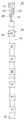
図2A及び図2Bに示すように、本実施の形態のケーブル20は、内側に2本の給電用導線22、23と、その両側に1本ずつ配置された信号用導線24、25との合計4本の導線が配線されている。信号用導線24、25の本数は、主に制御素子によって決定される。使用する制御素子の種類によって必要な信号用導線の本数が異なるので、ここに図示されたケーブル20であれば、信号用導線が1本必要なタイプの制御素子と、2本必要なタイプの制御素子に対応できる。
発光モジュール30の発光素子32に発光ダイオードを使用する場合には、供給用導線22、23には直流電流を通電する。例えば、一方の供給用導線22を電圧入力線とし、他方の供給用導線23をグラウンドとする。2本の信号用導線24、25には、それぞれ異なる電気信号を送信するのに使用でき、例えば、一方の信号用導線24にクロック(CK)信号を、他方の信号用導線25にデジタル入力(DI)信号を送信できる。
As shown in FIGS. 2A and 2B, the
When a light emitting diode is used for the
ケーブル20の両側部には、信号用導線24、25を切断する位置まで切欠いた切欠き部26が形成されている。これにより、1本のケーブル内において、信号用導線24、25は断線状態になっている。また、切欠き部26は、ケーブル20を挟んだ両側に形成されており、一対の切欠き部26と見なすことができる。図2Aでは、一対の切欠き部26は、相対する位置に同じ形状で形成されているが、位置が多少ずれても、また異なる形状することもできる。いずれの場合でも、一対の切欠き部26が、発光モジュールの内部に配置されるように形成する必要がある。
On both sides of the
ケーブル20の給電用導線22、23は、発光モジュール内の発光素子32に電力を供給するため、設定された電気容量よりも大容量の導線を使用する必要がある。これに対して、信号用導線24、25は、発光モジュール30の発光色や光度を制御する電気信号を流すだけであるので、電気容量の小さい導線(直径の細い電線)を使用することができる。すなわち、本発明では、信号用導線24、25の直径を、給電用導線22、23よりも小径にすることができる。信号用導線24、25が小径であると、機械的に切断する時の機械的応力が小さくできるので、ケーブル20に切欠き部26を形成しやすくなる点で好ましい。
In order to supply electric power to the
本実施の形態に示したような接続形態(シリーズ接続)の発光装置10では、発光モジュール30の向きが一方向に揃っていることが必要である。また、ケーブル20の4本の導線22〜25は、全て異なる機能を有するため、発光モジュール30の配線ミスをすると、発光モジュール30の破損につながる。そのため、ケーブル20に対する発光モジュール30の向きを確実に揃えることが重要である。そこで、ケーブル20の断面形状を線対称でも、点対称でもない形状(このような断面形状を、本明細書では非対称形状と称する)にすることにより、誤った向きの発光モジュール30を取着不可能にすることが好ましい。すなわち、ケーブル20の長手方向に直交する面におけるケーブル20の断面の平面形状は略長矩形又は長矩形から変形した略多角形となるため、対向して配置される2本の辺(場合によっては屈曲した線)の組みが通常は2組存在している。そのうちの少なくとも1組の辺(又は屈曲線)において、互いの寸法や形状が相違していれば、ケーブル20の断面を非対称形状とすることができる。断面形状が非対称であれば、発光モジュール30の固定方向を一義的に決定することが可能である。
In the
ケーブル20の断面形状を非対称にする一例としては、例えば図2Bに示すように、略矩形の頂部のうち、1箇所27だけを直角にして、他の3箇所を曲線にすればよい。この場合には、略長矩形の対向する1組の短辺は、頂部27と接続している一方の短辺は一端が曲線で他端が直線になっているのに対し、他方の短辺は、両端とも曲線である。また、略長矩形の対向する1組の長辺も、同様に形状が相違していると見なすことができる。このように、対向する辺の形状を一部異ならせることにより、断面形状を非対称形状とすることができる。
また、これ以外にも、断面の一部に凹部や凸部を設けたり、1辺を傾斜させた台形状にしたりすることにより、対向する辺の形状及び/又は寸法を異ならせることができる。
As an example in which the cross-sectional shape of the
In addition to this, the shape and / or the dimension of the opposing sides can be made different by providing a concave portion or a convex portion in a part of the cross section or forming a trapezoidal shape with one side inclined.
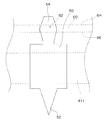
図3〜図5Bは、上述のケーブル20に取着するのに適した発光モジュール30の構成を示している。図3に図示した発光モジュール30用のケース40は、略矩形の有底容器のような形状をした本体41と、本体41の開口側(発光モジュール30の発光面側になる)に固定されるマスク44と、本体41の裏面側に固定されるケーブルガイド42とを含んでいる。さらに、ケース40は、必要に応じて、ケーブルガイド42の裏面側に固定するバーガイド部461を含むことができる。
3 to 5B show a configuration of the
図3に示すように、ケース40の本体41は、有底容器の底部を構成する区画壁411を有している。この区画壁411は、中央に貫通孔が1つ形成され、そしてその貫通孔の周囲に6本の導電端子50が埋め込まれている。導電端子50は、一方向が長めの板状体から成る部品である。図4に詳細に示すように、導電端子50は、鋭利な先端部52と、狭幅に成形された他端部54とを有している。導電端子50は、中間部分が区画壁411の内部に固定されており、先端部52が本体41の外側に、後端部54が本体41の内側に、それぞれ突出している。
As shown in FIG. 3, the
ケース40とケーブル20とを組み立てたときに、導電端子50の先端部52は、ケーブル20に穿刺される。このとき、給電用導線22、23の各々に、導電端子50が1本ずつ穿刺される。例えば、給電用導線22には穿刺位置221に、給電用導線23には穿刺位置231に、導電端子50が穿刺される。また、信号用導線24、25の各々には、信号用導線24、25の切断部分を挟んで、2本の導電端子50が穿刺される。例えば、一方の信号用導線24には、切欠き部26の両側に位置する穿刺位置241、242にそれぞれ1本ずつ導電端子50が穿刺され、同様に、他方の信号用導線25には、切欠き部26の両側に位置する穿刺位置251、252にそれぞれ1本ずつ導電端子50が穿刺される。よって、本実施の形態では、ケース40に備えられた導電端子50の本数は、給電用導線22、23に穿刺される2本と、信号用導線24、25に穿刺される導電端子4本との合計6本となっている。
導電端子50を給電用導線22、23や信号用導線24、25に穿刺することにより、導電端子50と各導線22〜24とは電気的に接続される。
When the
By puncturing the
このような導電端子の穿刺による通電方法は、ケーブル20の被覆を前もって剥離する前準備が不用であり、また、導線と発光モジュールの端子とをハンダ付けする必要もない。そのため、発光装置の組立を簡略化できる点で有利である。特に、ケーブル20と発光モジュール30とをハンダ付けしていないことは、発光モジュール30を個別に交換する場合にも有利である。例えば、本発明の発光装置10では、発光装置10に取着された複数の発光モジュール30のうち、1個〜数個の発光モジュール30が故障した場合、故障した発光モジュール30だけを新たな発光モジュール30と交換することができる。そのとき、発光モジュール30がハンダ付けされていれば、ハンダを除去する作業が必要になる。これに対して、本実施の形態のように導電端子50の穿刺のみで導通されていれば、導電端子50は簡単に抜き取ることができる。
Such an energization method by puncturing the conductive terminal does not require preparation before peeling off the covering of the
図4の導電端子50の他端部54には、図5A及び図5Bに示すような回路基板60が固定される。回路基板60は、両面に配線プリント(図示せず)が施されており、発光面64側に発光素子32が、裏面66側に制御素子34が固定されている。また、回路基板66には、外部電源との通電に使用されるスルーホール62が形成されている。本発明では、このスルーホール62に導電端子50の後端部54を圧入することにより、ハンダや導電性接着剤を使用することなく、回路基板60と導電端子50とを導通状態で固定することができる。
A
回路基板60を導電端子50に圧入法によって固定できるように、回路基板60のスルーホール62は、導電端子50の後端部54の配置に合わせて形成されている。このとき、図5Aに図示するように、スルーホール62から回路基板60の縁部までの距離Xと距離Yとを異ならせることにより、回路基板60の設置ミスを防止することができる。例えば、図5A及び図5Bのスルーホール62だけに着眼すると、6個のスルーホール62は点対称の配置となっている。そのため、もし距離Xと距離Yとが等しければ、回路基板60は、所定の向きでも、180°回転した向きでも、導電端子50に圧入することができる。ところが、回路基板60に固定した発光素子32や制御素子34は正負極が存在するので、誤った向きで導電端子50に圧入すれば不良品であり、もし通電すれば発光素子32や制御素子34が破壊する可能性が高い。そこで、回路基板60を点対称操作や線対称操作を行ったときに、操作後のスルーホール62が、元のスルーホール62の位置と一致しないように、回路基板60にスルーホール62を配置することにより、回路基板60の圧入方向を一義的に決定することができる。
The through
再度、図3を参照すると、ケース40は、本体41と、本体41の裏面側に固定するケーブルガイド部42とによって、ケーブル20を挟持できる。ケーブルガイド部42は、ケーブル20の外形に適合したケーブル受容くぼみ425を有しており、同様に、本体41も、裏面側にケーブル受容くぼみ415を有している。ケース40を組み立てるとき、図6のように、この2つのケーブル受容くぼみ415、425の間にケーブル20を配置すれば、ケーブル受容くぼみ415、425はケーブル20の断面形状に適合した貫通孔(これをケーブル受容部405と称する)を構成して、ケーブル20を挟持できる。
Referring to FIG. 3 again, the
図3及び図6に図示されるように、ケーブルガイド部42は、ケーブル受容くぼみ425に、ケーブル20の切欠き部26に嵌合する2つの突起部421を備えている。ケーブル20をケーブル受容部405で挟持する際には、まず、ケーブル20を、ケーブルガイド部42に接触させ、ケーブルガイド部42の突起部421をケーブル20の切欠き部26に嵌め込み、その状態で、本体41とケーブルガイド部42とを組み合わせる。この方法によれば、ケーブル20に所定間隔で切欠き部26が形成されていれば、その切欠き部26に合わせて発光モジュール30を固定できるので、発光モジュール30の離間を簡便に行うことができる。
As shown in FIGS. 3 and 6, the
また、ケーブル20の両側部に一対の切欠き部26が形成され、そして、一対の切欠き部26を、一対の突起部421によって支持(仮固定)することにより、ケーブル20は、ケーブルガイド部42によって両側部から挟み込まれる形で仮固定される。このように、発光モジュール30が完全に組み立てられるまでの間、ケーブル20は所定の位置に保持されて、長手方向にも幅方向にもずれることはない。
In addition, a pair of
このようなケーブル20の仮固定方法と、特許文献3のような貫通孔に位置決めピンを挿入する位置決め方法とを比較すると、特許文献3の問題点として考えられる(1)貫通孔を中心としてコンジットが回転可能なこと、(2)薄肉方向に貫通した貫通孔に挿通する際に位置決めピンが傾斜する可能性があること、そして(3)貫通孔内での揺動が可能であると推測できること、の3点は、本発明のケーブル20に突起部42を組み合わせることにより、全て解決される。
さらに、ケーブル20を突起部421により支持することは、仮固定だけでなく、ケーブル20が本体41とケーブルガイド部42とに挟持された後には、ケーブル20の抜け止め機構として機能する。よって、特許文献1及び2では、ケーブル20を引き抜く力がかかったとき、導電端子に応力がかかり、導電端子の変形や破損による発光モジュール30の接触不良が起こる可能性があるが、本発明では、導電端子50に応力がかかりにくいので、そのような問題が起こらない。
When such a temporary fixing method of the
Furthermore, supporting the
ケース40のケーブル受容部405の断面形状は、ケーブル20の断面形状に一致させることにより、ケーブル20の挟持を確実にするのが好ましい。よって、上述のように、ケーブル20の断面形状を非対称にした場合には、ケーブル受容部405の断面形状も非対称にする。例えば、図2Bに示すように、ケーブル20の断面形状を略矩形とし、その頂部のうち1箇所27だけを直角にするのであれば、それに対応して、ケーブル受容部405にも直角部分を形成する。図3及び6では、本体41のケーブル受容くぼみ415に直角部分417を形成している。これにより、ケーブル20にケース40を取り付けるときに、必ず正しい向きで取着できるので好ましい。
The cross-sectional shape of the
<変形例>
発光モジュールに使用される制御素子34によっては、図8A及び図8Bのように、信号用導線25が1本のケーブル200を使用できる。図8A及び図8Bのケーブル200は、図2A及び図2Bのケーブル20よりも断面積が小さいので、ケーブルの重量を軽くすることができる。よって、ケーブル200を使用すれば、同じ重量で長い発光装置10を準備でき、逆に、同じ長さで軽量の発光装置10を製造することができる。
<Modification>
Depending on the
図8A及び図8Bに示すように、変形例のケーブル200は、2本の給電用導線22、23と、その外側に配置された1本の信号用導線25との合計3本の導線が配線されている。
ケーブル200の片側には、信号用導線25を切断する位置まで切欠いた切欠き部26が形成されている。これにより、1本のケーブル内において、信号用導線25は断線状態になっている。切欠き部26は、発光モジュールの内部に配置されるように形成する必要がある。
As shown in FIGS. 8A and 8B, the
On one side of the
このケーブル200は、図2Aのケーブル20と同様に発光モジュール30と組み合わせて発光装置10とすることができる。しかしながら、ケーブル200には、切欠き部26が片側にしかないので、図3及び図6に示されたケーブルガイド42の突起部421を、切欠き部26の個数に合わせて変更(すなわち、突起部421を2つから1つに変更)すのが好ましい。
The
変形例のケーブル200も、切欠き部26に突起部421を嵌め込むことにより、発光モジュール30の位置決めを容易に行うことができる。
また、ケーブルガイド42に、ケーブル200の外形に適合したケーブル受けくぼみ425を形成すれば、切欠き部26と突起部421との嵌合が1箇所だけであっても、比較的安定してケーブル200を仮固定できる。よって、発光モジュール30が完全に組み立てられるまでの間、ケーブル200は所定の位置に保持されて、長手方向にも幅方向にもずれにくい。
The
In addition, if a
ケーブル200に穿刺する導電端子50は、給電用導線22、23の各々に1本ずつと、信号用導線25に2本の合計4本になる。穿刺位置は、図2と同様に、例えば導電端子50が1本ずつ穿刺される。例えば、給電用導線22には穿刺位置221に、給電用導線23には穿刺位置231に、導電端子50が穿刺される。また、信号用導線25には、切欠き部26の両側に位置する穿刺位置251、252にそれぞれ1本ずつ導電端子50が穿刺される。
これに合わせて、ケーブル200に取り付ける発光モジュール30のケース40では、本体41(図3及び図6参照)の区画壁411に固定されている導電端子50の本数を、6本から4本に変更されるであろう。
There are four
Accordingly, in the
さらに、ケーブル200を使用する場合には、図5A、図5B及び図6に示すような回路基板60でも、スルーホール62の個数を4個に変更することもできる。ただし、6個のスルーホール62のうち、4個を使用して、2つを使用しない方法で対応することもできる。
Furthermore, when the
本実施の形態では、ケーブル20又はケーブル200を用いた発光装置10を開示しているが、いずれの発光装置も、図9A〜図9Eに示すような様々な用途が考えられる。
図9Aは、ライン状の発光装置10の上端及び下端を枠体等に固定した固定ブロックであり、例えば薄型のディスプレイとして使用できる。
図9Bは、奥行きのある立体ディスプレイを図示している。この立体ディスプレイでは、まず、水平方向に固定した棒に、複数の発光装置10をぶら下げたすだれ状ディスプレイ921〜924を複数作製し、その複数のすだれ状ディスプレイ921〜924を平行に配列して構成されている。
図9A及び図9Bの用途では、発光モジュール30が、常に所定の方向を向いているのが好ましい。よって、ケーブル20(ケーブル200)が剛直であるか、又は可撓性を有するものの比較的ねじれにくいことが望ましい。
In the present embodiment, the
FIG. 9A is a fixed block in which the upper and lower ends of the line-shaped
FIG. 9B illustrates a stereoscopic display with depth. In this three-dimensional display, first, a plurality of
9A and 9B, it is preferable that the
また、図9Cでは、発光装置10は、柱状のオブジェに巻き回されており、図9Dでは樹木に取り付けられている。これらの用途では、発光装置10を構造物の形状に沿わせる必要があるので、可撓性のケーブル20(ケーブル200)を使用する。
Moreover, in FIG. 9C, the light-emitting
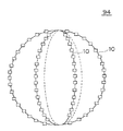
図9Eは、発光装置10を半円状に成形し、それを複数接続して、球状のイルミネーションオブジェ94を構成した例である。このオブジェ94のように、発光装置10自体が所定の形状を維持するのが困難である場合には、発光装置10を支持する帯状支持体を使用するのが好ましい。例えば、図10には、剛体のフラットバー80を発光装置10の背面側に取着した例を図示しているフラットバー80は、図3に示すようなバーガイド46を使用して、発光モジュール30の背面側に固定することができる。この構成であると、発光装置10は、複数箇所でフラットバー80に固定できるので、フラットバー80の形状に沿ったイルミネーションオブジェを容易に製造することができる。バーガイド46は、発光モジュール30の背面に隠れるので、イルミネーションオブジェ94の外観をすっきり見せることができる。
FIG. 9E shows an example in which a light-emitting
また、本発明では、使用状態において一部の発光モジュール30が破損した場合に、その破損した発光モジュール30のみを新たな発光モジュール30に交換できる。破損した発光モジュール30のケース40を破壊してケーブル20から取り外した後に、同じ位置に新たな発光モジュール30を簡単に取着できるので、例えば図9Aのような発光ブロックのまま修理が可能である。また、発光モジュール30の交換は、発光装置10自体を交換するのに比べて安価にできるので、維持費を抑制できるので好ましい。なお、発光モジュール30をケーブル20に取着する際に、導電端子50は、取り外した発光モジュールによって既に穿刺された部分に再度穿刺することになるが、シース部材28に粘弾性を有するものを使用すれば、先の穿刺穴は塞がるので、ケーブル20は、繰り返しの穿刺に耐えることができる。
Further, in the present invention, when some of the
以下に、発光装置10の各部品の組立て手順について、図6を参照して説明する。なお、この組立方法で説明したケーブル20は、ケーブル200と交換可能である。
(工程1)
ケーブル20の切欠き部26近傍に、ケーブルガイド部42を接触させる。このとき、ケーブル受容くぼみ425にケーブル20の長手方向を合わせて、さらに突起部421をケーブル20の切欠き部に嵌め込む。これにより、ケーブル20の所定位置に発光モジュール30を固定することが可能になる。
Below, the assembly procedure of each component of the light-emitting
(Process 1)
The
(工程2)
ケーブルガイド部42のスライドプレート423を、ケース40の本体41のレール溝413にスライドさせながら挿入して、本体41をケーブル20に近づける。本体41の裏面側には、6本の導電端子50の先端部52が突出しているので、本体41をケーブル20に押圧することにより、先端部52をケーブル20に穿刺する。このとき、ケーブル20はケーブルガイド部42に仮固定されて、先端部52とケーブル20内部の導線22〜25が所定の位置関係になっている。また、ケーブル20が仮固定されているので、本体41の押圧時にケーブル20がずれることがない。よって、固定時に、導電端子50とケーブル20との位置や向きを配慮する必要がなく、複数の導電端子50を位置最適位置に容易に穿刺することができる。
導電端子50がケーブル20の所定の深さまで穿刺されると、本体41とケーブルガイド部42とが接触して、ケーブル20を挟持する。このとき、本体41の係合突起(フック)412が、ケーブルガイド部42の係合凹部422に係止される。こうして、ケーブル20に、ケース40の本体41が固定される。
(Process 2)
The
When the
(工程3)
ケース40の本体41の発光面側から本体41の内部に、回路基板60を挿入する。このとき、回路基板60は、裏面側66を本体41に対面させた状態で、且つ回路基板60に形成されたスルーホール62が、導電端子50の後端部54の位置を適合する向きで挿入しなくてはならない。回路基板60を導電端子50に押圧して、スルーホール62に導電端子50の後端部54を圧入する。回路基板60は、スルーホール62を介して、導電端子50と導通し、且つ固定される。
(Process 3)
The
(工程4)
ケース40の本体41の発光面側に、マスク44を固定する。マスク44は、リフレクタとして機能させることや、又はレンズやプリズム等を組み込んで発光方向の制御素子として機能させることができる。
(Process 4)
A
上記の工程1〜4を、ケーブルに取着する発光モジュール30の回数だけ行うことにより、本発明の発光装置10を得ることができる。
The
次に、各構成について詳述する。
(ケーブル20)
ケーブル20に使用される給電用導線22、23及び信号用導線24、25は、錫メッキ軟銅線を素線とした撚り線を使用することができる。各導線の絶縁被覆29は、耐熱ビニルなどを用いることができる。また、絶縁被覆29は導線ごとに異なる色に着色すると、機能の異なる導線を区別するのに好適である。
シース部材28は、耐候性に優れ、強度の高いものを用いることが好ましく、特に、熱可塑性エラストマー(TPE:Thermoplastic Elastomers)、エチレンプロピレンゴム(EPDM:Ethylene Propylene Diene Methylene Linkage)など使用することができる。
ケーブル20をシース部材28で一体にするには、共押出しなどの方法を利用できる。
Next, each configuration will be described in detail.
(Cable 20)
The feeding
As the
In order to integrate the
(ケース40)
ケース40の本体41、ケーブルガイド部42、マスク44及びバーガイド46は、ポリカーボネート(PC)、ABS樹脂等の耐熱または耐候性を有する熱可塑性樹脂を、射出成形法によって製造することができる。なお、本体41の製造時には、射出成形に使用する金型の区画壁411の位置に導電端子50を配置し、その後に射出成形すれば、本体41の成形と同時に区画壁411に導電端子50を埋め込むことができ、且つ導電端子50が区画壁411にしっかり固定されるので好ましい。
また、これらの部品は、ディスプレイ用途に使用する場合は黒色が好ましく、一般的なカーボンブラックを樹脂材料に混入して着色させることができる。また、イルミネーション等の装飾に使用する場合は、背景色に合わせ色々な色に着色することが好ましい。
(Case 40)
The
These parts are preferably black when used for display applications, and can be colored by mixing general carbon black into a resin material. Moreover, when using for decorations, such as illumination, it is preferable to color in various colors according to a background color.
(導電端子50)
導電端子50は、銅板をプレス型によって打ち抜き加工して製造する。先端部52は、ケーブル20のシース部材28及び絶縁皮膜29を貫通できるように尖らせてある。後端部54は、回路基板60のスルーホール62を圧入固定できるように、後端部54から先端部52方向に向かって徐々に幅が広くされている。導電端子50の中間部分は、ケース40の本体41の区画壁411に埋没されて、導電端子50を本体41に固定している。この固定力を高めるために、導電端子50の中間部分の幅を先端部52及び後端部54よりも広くして、表面積を大きくしている。
(Conductive terminal 50)
The
(発光素子62)
発光素子62には、例えば発光ダイオード(LED)を使用することができる。また、マルチカラーを発光可能な発光装置10を得る場合には、例えば、3原色に対応した赤色LED、緑色LED及び青色LEDの3つを、1つの発光モジュール30に組み込むことができる。これらのLEDは、制御素子34によって個々に発光強度が調節できるので、その3色の混色の程度によって、様々な色を発光することができる。また、1つの発光装置10の発光モジュール30ごとに、異なる色に発光させることもできるので、ディスプレイとして使用することも可能である。
(Light emitting element 62)
As the
(制御素子34)
制御素子としては、集積回路(IC)を使用することができる。各発光モジュール30に内蔵される制御素子34は、切断された信号用導線24、25によって直列的に接続され、信号用導線24、25を通じて全ての制御素子34に異なるアドレスを付与することにより、1回の信号送信によって、制御素子34ごとに異なる命令を下すことができる。これを利用して、発光モジュール30ごとに異なる発光色にすることができる。
(Control element 34)
An integrated circuit (IC) can be used as the control element. The
本発明の発光装置10は、単独でイルミネーションとして使用でき、また複数を組み合わせて平面ディスプレイとして使用することができる。
The
10 発光装置
20、200 ケーブル
22、23 給電用導線
24、25 信号用導線
28 シース部材
30 発光モジュール
32 発光素子
34 制御楚々医
40 ケース
41 ケースの本体
42 ケーブルガイド部
421 突起部
44 マスク
46 バーガイド部
50 導電端子
52 導電端子の先端部
54 導電端子の後端部
60 回路基板
62 スルーホール
DESCRIPTION OF
Claims (9)
前記ケーブルは、並列に配置した少なくとも4本の導線と、前記4本の導線を被覆して一体にするシース部材と、を含むフラットケーブルであり、
前記少なくとも4本の導線のうち、前記ケーブルの両側部に位置する2本が信号用導線として、前記信号用導線以外の2本が給電用導線として使用され、
前記ケーブルは、その両側部に、前記2本の信号用導線を切断するように切欠き部が形成されていることを特徴とする発光装置用ケーブル。 A light-emitting device cable that is used in a light-emitting device in which a plurality of light-emitting modules are arranged in a row and that can control the light emission color and / or intensity of the light-emitting module,
The cable is a flat cable including at least four conducting wires arranged in parallel and a sheath member that covers and integrates the four conducting wires,
Of the at least four conductors, two positioned on both sides of the cable are used as signal conductors, and two other than the signal conductors are used as power supply conductors,
The cable for a light-emitting device, wherein the cable has notches formed on both sides thereof so as to cut the two signal conductors.
前記ケーブルは、並列に配置した少なくとも3本の導線と、前記3本の導線を被覆して一体にするシース部材と、を含むフラットケーブルであり、
前記少なくとも3本の導線のうち、前記ケーブルの両側部に位置する2本のうちいずれか1本が信号用導線として、前記信号用導線以外の2本が給電用導線として使用され、
前記ケーブルは、その側部に、前記1本の信号用導線を切断するように切欠き部が形成されていることを特徴とする発光装置用ケーブル。 A light-emitting device cable that is used in a light-emitting device in which a plurality of light-emitting modules are arranged in a row and that can control the light emission color and / or intensity of the light-emitting module,
The cable is a flat cable including at least three conductors arranged in parallel and a sheath member that covers and integrates the three conductors.
Of the at least three conductors, one of the two conductors located on both sides of the cable is used as a signal conductor, and two other than the signal conductor are used as power supply conductors,
A cable for a light emitting device, wherein a notch portion is formed on a side portion of the cable so as to cut the one signal conductor.
前記発光モジュールは、
前記発光素子を制御する制御素子と、
前記発光素子及び前記制御素子を収容するケースと、
前記制御素子と導通され、前記ケースを貫通してケース外部に突出した複数の導電端子と、を有し、
前記ケーブルは、
並列に配置した少なくとも4本の導線と、
前記4本の導線を被覆して一体にするシース部材と、を含むフラットケーブルであり、
前記少なくとも4本の導線のうち、前記ケーブルの両側部に位置する2本が信号用導線で、前記信号用導線以外の2本が給電用導線であり、
前記ケーブルには、その両側部に、前記2本の信号用導線を切断するように切欠き部が形成されており、
前記信号用導線の各々には、前記信号用導線の前記切欠き部を挟んで2本の導電端子が穿刺されて、該2本の導電端子と前記信号用導線とが電気的に接続されており、
前記ケースが、前記ケーブルの前記切欠き部に嵌合される突起部を備えて、前記ケーブルを支持することを特徴とする発光装置。 A light-emitting device comprising: a plurality of light-emitting modules including one or more light-emitting elements; and a cable capable of controlling a light emission color and / or light intensity of the light-emitting module,
The light emitting module
A control element for controlling the light emitting element;
A case for housing the light emitting element and the control element;
A plurality of conductive terminals that are electrically connected to the control element and project outside the case through the case;
The cable is
At least four conductors arranged in parallel;
A sheath member that covers and integrates the four conductive wires,
Of the at least four conductors, two located on both sides of the cable are signal conductors, and two other than the signal conductors are power feeding conductors,
The cable is formed with notches on both sides thereof so as to cut the two signal conductors,
Each of the signal conductors is pierced with two conductive terminals across the notch of the signal conductor, and the two conductor terminals and the signal conductor are electrically connected. And
The light emitting device according to claim 1, wherein the case includes a protrusion that is fitted into the notch of the cable and supports the cable.
前記発光モジュールは、
前記発光素子を制御する制御素子と、
前記発光素子及び前記制御素子を収容するケースと、
前記制御素子と導通され、前記ケースを貫通してケース外部に突出した複数の導電端子と、を有し、
前記ケーブルは、
並列に配置した少なくとも3本の導線と、
前記3本の導線を被覆して一体にするシース部材と、を含むフラットケーブルであり、
前記少なくとも3本の導線のうち、前記ケーブルの両側部に位置する2本のうちいずれか1本が信号用導線で、前記信号用導線以外の2本が給電用導線であり、
前記ケーブルには、その側部に、前記1本の信号用導線を切断するように切欠き部が形成されており、
前記信号用導線には、前記信号用導線の前記切欠き部を挟んで2本の導電端子が穿刺されて、該2本の導電端子と前記信号用導線とが電気的に接続されており、
前記ケースが、前記ケーブルの前記切欠き部に嵌合される突起部を備えて、前記ケーブルを支持することを特徴とする発光装置。 A light-emitting device comprising: a plurality of light-emitting modules including one or more light-emitting elements; and a cable capable of controlling a light emission color and / or light intensity of the light-emitting module,
The light emitting module
A control element for controlling the light emitting element;
A case for housing the light emitting element and the control element;
A plurality of conductive terminals that are electrically connected to the control element and project outside the case through the case;
The cable is
At least three conductors arranged in parallel;
A sheath member that covers and integrates the three conductive wires,
Of the at least three conductors, one of the two conductors located on both sides of the cable is a signal conductor, and two other than the signal conductor are power feeding conductors,
The cable has a notch formed on the side thereof so as to cut the one signal conductor.
Two conductive terminals are punctured across the notch of the signal conductor, and the two conductor terminals and the signal conductor are electrically connected to the signal conductor,
The light emitting device according to claim 1, wherein the case includes a protrusion that is fitted into the notch of the cable to support the cable.
前記回路基板が、前記導電端子に対応する位置にスルーホールを備え、
前記スルーホールに前記導電端子の端部を圧入することにより、前記回路基板が前記導電端子に導通され且つ固定されることを特徴とする請求項5乃至7のいずれか1項に記載の発光装置。 The control element is mounted on a circuit board;
The circuit board includes a through hole at a position corresponding to the conductive terminal;
The light emitting device according to claim 5, wherein the circuit board is electrically connected to and fixed to the conductive terminal by press-fitting an end portion of the conductive terminal into the through hole. .
Priority Applications (5)
| Application Number | Priority Date | Filing Date | Title |
|---|---|---|---|
| JP2007049912A JP4259584B2 (en) | 2007-02-28 | 2007-02-28 | Light emitting device cable and light emitting device using the same |
| CN2008100813656A CN101255970B (en) | 2007-02-28 | 2008-02-25 | Lighting apparatus |
| EP08151990.2A EP1965123B1 (en) | 2007-02-28 | 2008-02-27 | Lighting apparatus cable and lighting apparatus using the same |
| KR1020080017773A KR101468054B1 (en) | 2007-02-28 | 2008-02-27 | Cable for light emitting device and light emitting device using the same |
| US12/071,920 US7740386B2 (en) | 2007-02-28 | 2008-02-27 | Lighting apparatus cable and lighting apparatus using the same |
Applications Claiming Priority (1)
| Application Number | Priority Date | Filing Date | Title |
|---|---|---|---|
| JP2007049912A JP4259584B2 (en) | 2007-02-28 | 2007-02-28 | Light emitting device cable and light emitting device using the same |
Publications (2)
| Publication Number | Publication Date |
|---|---|
| JP2008218013A JP2008218013A (en) | 2008-09-18 |
| JP4259584B2 true JP4259584B2 (en) | 2009-04-30 |
Family
ID=39431079
Family Applications (1)
| Application Number | Title | Priority Date | Filing Date |
|---|---|---|---|
| JP2007049912A Active JP4259584B2 (en) | 2007-02-28 | 2007-02-28 | Light emitting device cable and light emitting device using the same |
Country Status (5)
| Country | Link |
|---|---|
| US (1) | US7740386B2 (en) |
| EP (1) | EP1965123B1 (en) |
| JP (1) | JP4259584B2 (en) |
| KR (1) | KR101468054B1 (en) |
| CN (1) | CN101255970B (en) |
Families Citing this family (38)
| Publication number | Priority date | Publication date | Assignee | Title |
|---|---|---|---|---|
| JP5006251B2 (en) * | 2008-05-08 | 2012-08-22 | 古河電気工業株式会社 | Connection structure |
| JP5203034B2 (en) * | 2008-05-08 | 2013-06-05 | 古河電気工業株式会社 | Connection structure |
| US8132935B2 (en) * | 2008-09-01 | 2012-03-13 | Samsung Led Co., Ltd. | Light emitting module |
| JP4772882B2 (en) | 2009-03-06 | 2011-09-14 | 日本航空電子工業株式会社 | Wiring board and light emitting device |
| JP2011233356A (en) * | 2010-04-27 | 2011-11-17 | Sharp Corp | Light source module, display device, and lighting apparatus |
| KR200457319Y1 (en) * | 2010-05-10 | 2011-12-13 | 윤종석 | Rail for led support block assembly |
| US8662734B2 (en) * | 2010-08-23 | 2014-03-04 | Redwood Systems, Inc. | LED track lighting with flexible circuit |
| KR101300907B1 (en) * | 2010-10-01 | 2013-08-27 | 소닉스자펜 주식회사 | Lampshade connecting device, lampshade connected module and the light comprising the same |
| FR2973954B1 (en) * | 2011-04-06 | 2015-03-06 | David Zieder | CONNECTING BRACKET AND CORRESPONDING FLEXIBLE STRIP |
| CN102777810B (en) * | 2011-05-12 | 2016-04-06 | 欧司朗股份有限公司 | Light-emitting device and backlight light bar |
| GB2490887B (en) * | 2011-05-16 | 2016-05-04 | Libman Peter | Decorative light apparatus |
| CN103137253A (en) * | 2011-11-23 | 2013-06-05 | 达昌电子科技(苏州)有限公司 | Flat cable unit provided with light-emitting assembly |
| TWI443279B (en) * | 2012-03-05 | 2014-07-01 | Lextar Electronics Corp | Stretchable light-emitting module |
| JP2014063578A (en) * | 2012-09-20 | 2014-04-10 | Yazaki Corp | Pressure-welding connection unit |
| WO2014056539A1 (en) * | 2012-10-11 | 2014-04-17 | David Zieder | Connection support and corresponding flexible strip |
| CN104903644B (en) * | 2012-10-31 | 2019-07-05 | 米蒂尔格拉夫迪波特公司 | Lighting system |
| WO2014115936A1 (en) * | 2013-01-22 | 2014-07-31 | 주식회사 아이티앤티 | Led bar having structure capable of assembling block without cable |
| US10443824B2 (en) * | 2013-03-15 | 2019-10-15 | The Sloan Company, Inc. | Sign box lighting system |
| US10446065B2 (en) * | 2013-03-15 | 2019-10-15 | The Sloan Company, Inc. | Sign box lighting system |
| DE202014000264U1 (en) * | 2014-01-10 | 2015-04-13 | Novomatic Ag | lighting device |
| DE202014101257U1 (en) * | 2014-03-19 | 2015-07-01 | Zumtobel Lighting Gmbh | Lighting system |
| KR101613582B1 (en) * | 2014-05-13 | 2016-04-29 | (주)비젼라이팅 | LED module |
| CN104600452B (en) * | 2015-02-16 | 2016-08-24 | 深圳市华星光电技术有限公司 | Down straight aphototropism mode set and connecton layout |
| JP2016199059A (en) * | 2015-04-07 | 2016-12-01 | 鹿島建設株式会社 | Track short-circuit instrument |
| JP6213847B2 (en) * | 2015-09-09 | 2017-10-18 | 住友電装株式会社 | Wire guide device and holder for lightning decorative parts |
| KR101710324B1 (en) * | 2015-11-13 | 2017-02-27 | 주식회사 리움 | Charge measurable emitting cable |
| CA2948705A1 (en) * | 2015-11-18 | 2017-05-18 | Willis Electric Co., Ltd. | Combinatorial light string plug and receptacle |
| US10616977B2 (en) * | 2015-12-18 | 2020-04-07 | Signify Holding B.V. | Lighting strip |
| CN105895245B (en) * | 2016-06-22 | 2018-01-12 | 武汉博琼测控技术有限公司 | A kind of graduated scale ranging cable |
| CN205979306U (en) | 2016-08-03 | 2017-02-22 | 鹤山市银雨照明有限公司 | Flexible projecting lamp of LED |
| CN106382495A (en) * | 2016-11-24 | 2017-02-08 | 四川鋈新能源科技有限公司 | Flexible substrate LED lamp filament with adjustable electric conduction line and preparing technology |
| CN206320598U (en) * | 2016-11-25 | 2017-07-11 | 中山市尊宝实业有限公司 | A kind of light fixture connecting structure |
| KR200485237Y1 (en) * | 2017-06-20 | 2017-12-11 | 이철용 | Multimedia LED tower system |
| WO2019157614A1 (en) * | 2018-02-13 | 2019-08-22 | 陈晓红 | Light-emitting cable |
| US20200049329A1 (en) * | 2018-08-08 | 2020-02-13 | General lighting Electronic Co.,Ltd | Led strip that can be bent in three-dimensional space |
| JP7243540B2 (en) * | 2019-09-13 | 2023-03-22 | 株式会社オートネットワーク技術研究所 | Wiring material |
| CN112838153A (en) * | 2021-02-02 | 2021-05-25 | 东莞市华彩威科技有限公司 | LED lamp string, manufacturing method and LED device used in LED lamp string |
| US11346538B1 (en) * | 2021-05-17 | 2022-05-31 | Sikai Chen | LED lighting module with electrical power and data connections |
Family Cites Families (18)
| Publication number | Priority date | Publication date | Assignee | Title |
|---|---|---|---|---|
| US677891A (en) * | 1900-10-05 | 1901-07-09 | Otis Elevator Co | Controlling apparatus for elevators. |
| US5038001A (en) * | 1990-03-13 | 1991-08-06 | Amp Incorporated | Feature for orientation of an electrical cable |
| US5125846A (en) * | 1991-07-25 | 1992-06-30 | Molex Incorporated | Input-output electrical connector |
| US5238424A (en) * | 1991-12-05 | 1993-08-24 | Vindum Jorgen O | In-line extension cord |
| US6777891B2 (en) * | 1997-08-26 | 2004-08-17 | Color Kinetics, Incorporated | Methods and apparatus for controlling devices in a networked lighting system |
| US7217812B2 (en) * | 1999-01-29 | 2007-05-15 | United States Of America As Represented By The Secretary Of The Army | Extraneous DNA sequence that facilitates hantavirus gene expression |
| JP3857030B2 (en) | 2000-09-20 | 2006-12-13 | 積水樹脂株式会社 | Self-luminous sign |
| WO2002043220A1 (en) | 2000-11-27 | 2002-05-30 | Point Lumineux | Wiring system for large-dimension block diagrams |
| US6660935B2 (en) | 2001-05-25 | 2003-12-09 | Gelcore Llc | LED extrusion light engine and connector therefor |
| JP3706972B2 (en) | 2002-09-09 | 2005-10-19 | ユニメックス株式会社 | Conductive connector that can be attached to and detached from the power cord |
| US20040115984A1 (en) * | 2002-12-12 | 2004-06-17 | Rudy William J. | Light socket assembly for use with conductors arranged in a ribbon cable |
| JP4406256B2 (en) | 2003-06-20 | 2010-01-27 | 矢崎総業株式会社 | LED lamp module and lamp module assembly |
| WO2004114736A2 (en) * | 2003-06-20 | 2004-12-29 | Yazaki Corporation | Led illumination device |
| JP4286083B2 (en) | 2003-07-09 | 2009-06-24 | エムケー精工株式会社 | Light emitting device |
| US7114841B2 (en) * | 2004-03-22 | 2006-10-03 | Gelcore Llc | Parallel/series LED strip |
| JP4239013B2 (en) * | 2004-09-30 | 2009-03-18 | オムロン株式会社 | Multi-axis photoelectric sensor |
| US7160140B1 (en) * | 2005-07-13 | 2007-01-09 | Gelcore Llc | LED string light engine |
| JP4829755B2 (en) | 2006-07-27 | 2011-12-07 | コトヒラ工業株式会社 | Light emitting module array display device and light emitting module mounting member |
-
2007
- 2007-02-28 JP JP2007049912A patent/JP4259584B2/en active Active
-
2008
- 2008-02-25 CN CN2008100813656A patent/CN101255970B/en active Active
- 2008-02-27 US US12/071,920 patent/US7740386B2/en active Active
- 2008-02-27 EP EP08151990.2A patent/EP1965123B1/en active Active
- 2008-02-27 KR KR1020080017773A patent/KR101468054B1/en active IP Right Grant
Also Published As
| Publication number | Publication date |
|---|---|
| KR20080080030A (en) | 2008-09-02 |
| CN101255970A (en) | 2008-09-03 |
| KR101468054B1 (en) | 2014-12-02 |
| US7740386B2 (en) | 2010-06-22 |
| JP2008218013A (en) | 2008-09-18 |
| EP1965123A1 (en) | 2008-09-03 |
| EP1965123B1 (en) | 2017-08-16 |
| US20080205059A1 (en) | 2008-08-28 |
| CN101255970B (en) | 2012-08-29 |
Similar Documents
| Publication | Publication Date | Title |
|---|---|---|
| JP4259584B2 (en) | Light emitting device cable and light emitting device using the same | |
| JP4331590B2 (en) | Illuminated signs using light-emitting diodes | |
| EP2333407B1 (en) | LED Lighting assemblies | |
| US9696023B2 (en) | Electric connecting member and LED lamp using the same | |
| US20040007981A1 (en) | Chained led light source structure | |
| US20160025319A1 (en) | Holder, holder assembly and led assembly using holder assembly | |
| US20140369056A1 (en) | Light-emitting diode lamp assembly | |
| KR20110073824A (en) | Connecting member for led module and led module assembly including the same | |
| KR100860063B1 (en) | Led module assembly for signboard and method for manufacturing signboard using the same | |
| EP2080947A1 (en) | Flexible luminescent material | |
| TW201504567A (en) | Led assembly | |
| WO2007119908A1 (en) | Led module assembly for signboard and method for manufacturing signboard using the same | |
| US5951152A (en) | Light source housing apparatus and method of manufacture | |
| JP3148176U (en) | Fluorescent LED lighting | |
| US7833060B2 (en) | LED bulb assembly | |
| JP2015173217A (en) | Electronic device and connection method | |
| KR20100120071A (en) | Led module assembly for signboard and signboard adopting the same | |
| JP3706972B2 (en) | Conductive connector that can be attached to and detached from the power cord | |
| KR101279906B1 (en) | Lamp apparatus using light emitting diode | |
| US11828441B2 (en) | LED lamp manufactured by injection molding process | |
| KR20060083676A (en) | Light emitting diode assembly | |
| JP2003179264A (en) | Continuous connection connector of led and manufacturing method therefore | |
| KR100495103B1 (en) | A LED lamp for surface-mouting and a manufacturing method thereof | |
| JPH11265160A (en) | Light emitting diode assy, attaching method therefor and light emitting diode display | |
| JP2012054402A (en) | Light emitting device |
Legal Events
| Date | Code | Title | Description |
|---|---|---|---|
| A977 | Report on retrieval |
Free format text: JAPANESE INTERMEDIATE CODE: A971007 Effective date: 20090116 |
|
| TRDD | Decision of grant or rejection written | ||
| A01 | Written decision to grant a patent or to grant a registration (utility model) |
Free format text: JAPANESE INTERMEDIATE CODE: A01 Effective date: 20090120 |
|
| A01 | Written decision to grant a patent or to grant a registration (utility model) |
Free format text: JAPANESE INTERMEDIATE CODE: A01 |
|
| A61 | First payment of annual fees (during grant procedure) |
Free format text: JAPANESE INTERMEDIATE CODE: A61 Effective date: 20090202 |
|
| FPAY | Renewal fee payment (event date is renewal date of database) |
Free format text: PAYMENT UNTIL: 20120220 Year of fee payment: 3 |
|
| R150 | Certificate of patent or registration of utility model |
Ref document number: 4259584 Country of ref document: JP Free format text: JAPANESE INTERMEDIATE CODE: R150 Free format text: JAPANESE INTERMEDIATE CODE: R150 |
|
| FPAY | Renewal fee payment (event date is renewal date of database) |
Free format text: PAYMENT UNTIL: 20120220 Year of fee payment: 3 |
|
| FPAY | Renewal fee payment (event date is renewal date of database) |
Free format text: PAYMENT UNTIL: 20120220 Year of fee payment: 3 |
|
| FPAY | Renewal fee payment (event date is renewal date of database) |
Free format text: PAYMENT UNTIL: 20120220 Year of fee payment: 3 |
|
| FPAY | Renewal fee payment (event date is renewal date of database) |
Free format text: PAYMENT UNTIL: 20130220 Year of fee payment: 4 |
|
| R250 | Receipt of annual fees |
Free format text: JAPANESE INTERMEDIATE CODE: R250 |
|
| FPAY | Renewal fee payment (event date is renewal date of database) |
Free format text: PAYMENT UNTIL: 20130220 Year of fee payment: 4 |
|
| FPAY | Renewal fee payment (event date is renewal date of database) |
Free format text: PAYMENT UNTIL: 20140220 Year of fee payment: 5 |
|
| R250 | Receipt of annual fees |
Free format text: JAPANESE INTERMEDIATE CODE: R250 |
|
| R250 | Receipt of annual fees |
Free format text: JAPANESE INTERMEDIATE CODE: R250 |
|
| R250 | Receipt of annual fees |
Free format text: JAPANESE INTERMEDIATE CODE: R250 |
|
| R250 | Receipt of annual fees |
Free format text: JAPANESE INTERMEDIATE CODE: R250 |
|
| R250 | Receipt of annual fees |
Free format text: JAPANESE INTERMEDIATE CODE: R250 |
|
| R250 | Receipt of annual fees |
Free format text: JAPANESE INTERMEDIATE CODE: R250 |
|
| R250 | Receipt of annual fees |
Free format text: JAPANESE INTERMEDIATE CODE: R250 |
|
| R250 | Receipt of annual fees |
Free format text: JAPANESE INTERMEDIATE CODE: R250 |
|
| R250 | Receipt of annual fees |
Free format text: JAPANESE INTERMEDIATE CODE: R250 |
|
| R250 | Receipt of annual fees |
Free format text: JAPANESE INTERMEDIATE CODE: R250 |
|
| R250 | Receipt of annual fees |
Free format text: JAPANESE INTERMEDIATE CODE: R250 |
|
| R250 | Receipt of annual fees |
Free format text: JAPANESE INTERMEDIATE CODE: R250 |