JP4258340B2 - Pantograph detection device - Google Patents
Pantograph detection device Download PDFInfo
- Publication number
- JP4258340B2 JP4258340B2 JP2003354636A JP2003354636A JP4258340B2 JP 4258340 B2 JP4258340 B2 JP 4258340B2 JP 2003354636 A JP2003354636 A JP 2003354636A JP 2003354636 A JP2003354636 A JP 2003354636A JP 4258340 B2 JP4258340 B2 JP 4258340B2
- Authority
- JP
- Japan
- Prior art keywords
- pantograph
- image
- center point
- recognition target
- point
- Prior art date
- Legal status (The legal status is an assumption and is not a legal conclusion. Google has not performed a legal analysis and makes no representation as to the accuracy of the status listed.)
- Expired - Lifetime
Links
- 238000001514 detection method Methods 0.000 title claims description 31
- 238000012545 processing Methods 0.000 claims description 37
- 238000000034 method Methods 0.000 description 8
- 238000012937 correction Methods 0.000 description 7
- 238000006243 chemical reaction Methods 0.000 description 5
- 238000007796 conventional method Methods 0.000 description 2
- 239000011159 matrix material Substances 0.000 description 2
- 241000406668 Loxodonta cyclotis Species 0.000 description 1
- 238000006073 displacement reaction Methods 0.000 description 1
- 238000012423 maintenance Methods 0.000 description 1
Images






Landscapes
- Length Measuring Devices By Optical Means (AREA)
- Image Processing (AREA)
- Image Analysis (AREA)
Description
本発明は、パンタグラフが映るように電車に設置されたITVカメラの映像から、画像処理によりパンタグラフを検出する技術に関するものである。 The present invention relates to a technique for detecting a pantograph by image processing from an image of an ITV camera installed on a train so that the pantograph is reflected.
画像処理によりパンタグラフを検出する技術(特許文献1、特願2002−151840号参照)において、パンタグラフ検出は、映像と予め登録されたパンタグラフのパタンとのパタンマッチより検出している(特許文献2参照)。
斯かる技術では、カメラがパンタグラフの正面に設置する場合、1つのパンタグラフモデルのパタンマッチでパンタグラフを検出できる。
In such a technique, when the camera is installed in front of the pantograph, the pantograph can be detected by pattern matching of one pantograph model.
しかし、上述した背景技術では、図1に示す全体図のように、パンタグラフ1に対してカメラ2が斜向きに設置される場合、パンタグラフ1の見え方(アスペクト)が、パンタグラフ1の高さ変化に伴って、図4のように画像上で幾何変化する。
これにより1つのパンタグラフモデルを使用したパタンマッチでは、パンタグラフの高さ変化に伴ってずれた位置を検出する問題がある。
この問題を解決するため、パンタグラフの見え方が同じになるよう投影変換し位置ずれを排除しているが、投影変換には処理時間がかかる問題がある。
However, in the background art described above, when the
Thereby, in the pattern match using one pantograph model, there exists a problem of detecting the position which shifted | deviated with the height change of the pantograph.
In order to solve this problem, projection conversion is performed so that the pantograph looks the same, and positional deviation is eliminated. However, projection conversion has a problem that it takes processing time.
上記課題を解決する本発明の請求項1に係る画像処理によるパンタグラフ検出装置は、上下に移動するパンタグラフに対してカメラが斜向きに設置され、前記カメラで撮影された画像を画像処理にて前記パンタグラフの位置を計測する装置において、前記パンタグラフの上下移動に伴い前記パンタグラフの中心点が画像上で移動する直線軌跡を予め求めておき、入力画像から前記パンタグラフの中心点を求める際に、入力画像を直接認識して得られた前記パンタグラフの中心点を前記直線軌跡に乗るように補正することにより、前記パンタグラフの中心点を求めることを特徴とする。 In the pantograph detection device by image processing according to claim 1 of the present invention for solving the above-described problem, a camera is installed obliquely with respect to a pantograph that moves up and down, and an image captured by the camera is processed by image processing. In the apparatus for measuring the position of the pantograph, a linear locus in which the center point of the pantograph moves on the image as the pantograph moves up and down is obtained in advance, and when the center point of the pantograph is obtained from the input image, the input image The center point of the pantograph is obtained by correcting the center point of the pantograph obtained by directly recognizing the pantograph so as to be on the straight line locus.
上記課題を解決する本発明の請求項2に係る画像処理によるパンタグラフ検出装置は、上下に移動するパンタグラフに対してカメラが斜向きに設置され、前記カメラで撮影された画像を画像処理にて前記パンタグラフの位置を計測する装置において、前記パンタグラフの移動に伴い前記パンタグラフの中心点が画像上で移動する直線軌跡を予め求めておき、入力画像から前記パンタグラフの中心点を求める際に、前記直線軌跡に沿って画像認識することにより、前記パンタグラフの中心点を求めることを特徴とする。
The pantograph detection device by image processing according to
上記課題を解決する本発明の請求項3に係る画像処理によるパンタグラフ検出装置は、上下に移動するパンタグラフに対してカメラが斜向きに設置され、前記カメラで撮影された画像を画像処理にて前記パンタグラフの位置を計測する装置において、前記パンタグラフの中心点と他の2つの認識対象点を予め設定し、前記パンタグラフの上下移動に伴う2つの前記認識対象点の画像上のそれぞれの直線軌跡を求め、これらの直線軌跡の交点を求め、前記交点と前記パンタグラフの中心点を結ぶ第三の直線を求め、入力画像からパンタグラフの中心点を求める際に、入力画像を直接認識して得られた前記パンタグラフの中心点を前記第三の直線に乗るように補正することにより、前記パンタグラフの中心点を求めることを特徴とする。 According to a third aspect of the present invention, there is provided a device for detecting a pantograph by image processing, wherein a camera is installed obliquely with respect to a pantograph moving up and down, and an image photographed by the camera is processed by image processing. In the apparatus for measuring the position of the pantograph, the center point of the pantograph and the other two recognition target points are set in advance, and the respective linear trajectories on the images of the two recognition target points as the pantograph moves up and down are obtained. The intersection of these linear trajectories is obtained, the third straight line connecting the intersection and the center point of the pantograph is obtained, and when the center point of the pantograph is obtained from the input image, the input image is directly recognized and obtained. The center point of the pantograph is obtained by correcting the center point of the pantograph so as to be on the third straight line.
上記課題を解決する本発明の請求項4に係る画像処理によるパンタグラフ検出装置は、上下に移動するパンタグラフに対してカメラが斜向きに設置され、前記カメラで撮影された画像を画像処理にてパンタグラフの位置を計測する装置において、前記パンタグラフの中心点と他の2つの認識対象点を予め設定し、前記認識対象点をそれぞれ含む小領域を認識対象画像として登録するとともに、前記認識対象点と前記パンタグラフの中心点の関係を予め計算記憶し、前記パンタグラフの移動に伴う前記認識対象点に対するそれぞれの直線軌跡を予め計算し、入力画像より前記パンタグラフの位置を認識する際に、それぞれ前記直線軌跡に沿って前記小領域について画像認識を行うことにより、前記認識対象点の位置を求め、予め求めた前記認識対象点と前記パンタグラフの中心点との位置関係にもとづいて、入力画像の前記パンタグラフの中心点を求めることを特徴とする。 According to a fourth aspect of the present invention, there is provided a device for detecting a pantograph by image processing, wherein a camera is installed obliquely with respect to a pantograph that moves up and down, and an image captured by the camera is subjected to image processing. The center point of the pantograph and the other two recognition target points are set in advance, and a small region including each of the recognition target points is registered as a recognition target image. The relationship between the center points of the pantograph is calculated and stored in advance, the respective linear trajectories with respect to the recognition target points accompanying the movement of the pantograph are calculated in advance, and when the position of the pantograph is recognized from the input image, The position of the recognition target point is obtained by performing image recognition on the small region along the recognition, and the recognition obtained in advance Based on the positional relationship between the elephant point and the center point of the pantograph, and obtains the center point of the pantograph of the input image.
上記課題を解決する本発明の請求項5に係る画像処理によるパンタグラフ検出装置は、上下に移動するパンタグラフに対してカメラが斜向きに設置され、前記カメラで撮影された画像を画像処理にてパンタグラフの位置を計測する装置において、前記パンタグラフの中心点と他の2つの認識対象点を予め設定し、前記認識対象点をそれぞれ含む小領域を認識対象画像として登録するとともに、前記認識対象点と前記パンタグラフの中心点の関係を予め計算記憶し、入力画像を認識して前記パンタグラフの中心点を求め、予め計算した前記認識対象点と前記パンタグラフの中心点の位置関係に基づいた位置で前記小領域について画像認識を行うことにより、前記認識対象点を求め、求めた認識対象点の位置より前記パンタグラフの中心点を補正することを特徴とする。 According to a fifth aspect of the present invention, there is provided an apparatus for detecting a pantograph by image processing, wherein a camera is installed obliquely with respect to a pantograph moving up and down, and an image photographed by the camera is subjected to image processing. The center point of the pantograph and the other two recognition target points are set in advance, and a small region including each of the recognition target points is registered as a recognition target image. Pre-calculate and store the relationship between the center points of the pantograph, recognize the input image to obtain the center point of the pantograph, and the small region at a position based on the pre-calculated positional relationship between the recognition target point and the center point of the pantograph The recognition target point is obtained by performing image recognition on the image, and the center point of the pantograph is corrected from the position of the obtained recognition target point. And wherein the Rukoto.
上記課題を解決する本発明の請求項6に係る画像処理によるパンタグラフ検出装置は、上下に移動するパンタグラフに対してカメラが斜向きに設置され、前記カメラで撮影された画像を画像処理にてパンタグラフの位置を計測する装置において、前記パンタグラフの中心点と他の2つの認識対象点を予め設定し、前記認識対象点をそれぞれ含む小領域を認識対象画像として登録するとともに、前記認識対象点と前記パンタグラフの中心点の関係を予め計算記憶し、入力画像より前記パンタグラフの位置を認識する際に、前記小領域について画像認識を行うことにより、前記認識対象点を求め、予め計算した前記認識対象点と前記パンタグラフの中心点の位置関係に基づいた前記パンタグラフ中心点付近に制約して画像認識を行うことにより、前記パンタグラフの中心点を求めることを特徴とする。 According to a sixth aspect of the present invention, there is provided a device for detecting a pantograph by image processing, wherein a camera is installed obliquely with respect to a pantograph that moves up and down, and an image photographed by the camera is subjected to image processing. The center point of the pantograph and the other two recognition target points are set in advance, and a small region including each of the recognition target points is registered as a recognition target image. calculated beforehand stores a relation between the center point of the pantograph, in recognizing a position of the pantograph from the input image, by performing image recognition on the small area, it obtains the recognition target point, the recognition target in advance calculated By performing image recognition by constraining the vicinity of the pantograph center point based on the positional relationship between the point and the center point of the pantograph, And it obtains the center point of the serial pantograph.
請求項1に係るパンタグラフ検出装置では、上下移動するパンタグラフの中心が直線軌跡になる特徴を利用し、画像中のパンタグラフの中心が上下移動した2点からパタンマッチでずれるパンタグラフの中心を補正するので、パンタグラフの中心点を検出できる利点があり、2点から求めた単純な式によって、高速に中心を補正できる利点がある。 In the pantograph detection device according to the first aspect, the center of the pantograph that moves up and down is used as a straight line locus, and the center of the pantograph in the image is corrected by the pattern match from the two points where the center of the pantograph moves up and down. There is an advantage that the center point of the pantograph can be detected, and there is an advantage that the center can be corrected at high speed by a simple expression obtained from two points.
請求項2に係るパンタグラフ検出装置では、移動するパンタグラフの中心が直線軌跡になる特徴を利用し、画像中の直線軌跡付近に沿って小領域のパタンマッチを行い、パンタグラフの中心を求めており、1つの小領域を制約した探索範囲でパタンマッチするため、パンタグラフの中心が高速に得られる利点がある。
In the pantograph detection device according to
請求項3に係るパンタグラフ検出装置では、上下移動するパンタグラフが直線軌跡になる特徴を利用し、パタンマッチでずれるパンタグラフの位置を、パンタグラフの所定の5点で補正するものであり、5点から求めた単純な式によって、高速にパンタグラフ位置を補正できる利点がある。 In the pantograph detection device according to the third aspect, the pantograph that moves up and down is used as a straight line locus, and the position of the pantograph that is shifted by the pattern match is corrected by predetermined five points of the pantograph. In addition, there is an advantage that the pantograph position can be corrected at high speed by a simple formula.
請求項4に係るパンタグラフ検出装置では、移動するパンタグラフが画像上で直線軌跡になる特徴を利用し、パンタグラフの所定の5点からパンタグラフの位置を求めるものであり、2個の小領域を制約した探索範囲でパタンマッチするため、パンタグラフの位置が高速に得られる利点がある。 In the pantograph detection device according to the fourth aspect of the present invention, the moving pantograph uses a feature that becomes a linear locus on the image, and the position of the pantograph is obtained from predetermined five points of the pantograph, and two small regions are constrained. Since pattern matching is performed in the search range, there is an advantage that the position of the pantograph can be obtained at high speed.
請求項5に係るパンタグラフ検出装置では、パンタグラフ上に特徴的な形状が存在することを利用し、パタンマッチでずれるパンタグラフの検出位置を特徴的な形状を包括する小領域のパタンマッチで補正するものであり、小領域でかつ探索範囲を制約したパタンマッチ結果で補正するため、高速に位置補正できる利点がある。
The pantograph detection apparatus according to
請求項6に係るパンタグラフ検出装置では、パンタグラフ上に特徴的な形状が存在することを利用し、パタンマッチでパンタグラフを検出後、点線枠のようにパンタグラフを包括するモデルのパタンマッチで再確認するものであり、パタンマッチで再確認するため、検出結果の信頼性が向上する利点がある。
The pantograph detection apparatus according to
本発明は、以下に示す実施例1〜6が最良の形態である。 In the present invention, Examples 1 to 6 shown below are the best modes.
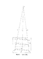
本発明の第一の実施例(2点からパンタグラフ中心補正)に係るパンタグラフ検出装置を図1に示す。
図1に示すように、パンタグラフ1に対してカメラ2が斜向きに設置され、カメラ2で撮影された画像はパンタグラフ検出装置3に取り込まれる。
FIG. 1 shows a pantograph detection apparatus according to the first embodiment of the present invention (pantograph center correction from two points).
As shown in FIG. 1, a
パンタグラフ検出装置3は、上下移動するパンタグラフ1の中心が図2の1点鎖線Lに示すように、直線の軌跡になる特徴を利用し、画像中のパンタグラフ中心が上下移動した2点から、パタンマッチでずれるパンタグラフ中心座標を補正する画像処理を行うものである。
なお、パンタグラフ検出装置は、ハードウェア的に構成しても良いが、画像処理を実行するプログラムをコンピュータに読み込ませることによりソフトウェア的に構成しても良い。
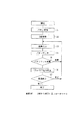
パンタグラフ検出装置3による画像処理を図8に示すフローチャートに従って説明する。
The
The pantograph detection device may be configured in hardware, but may be configured in software by causing a computer to read a program for executing image processing.
Image processing by the
先ず、図2の点線枠内のようにパンタグラフを包括する領域Aをしてモデルマッチング用のモデルデータとして登録する(ステップS1)。
次に、図2のように、予め上下動した位置でのパンタグラフ1の中心点P1,P2を画面上で指示して登録し、装置内のプログラムで直線Lを求めておく(ステップS2)。
中心点P1は、上方に位置する際のパンタグラフ1の中心で、中心点P2は中心点Plが下方へ位置する際の点である。中心点Pl,P2は精度上画像の上下の端に存在するのが望ましい。
以上のステップS1,S2を予め前処理しておく。
First, an area A including a pantograph as shown in the dotted frame in FIG. 2 is registered as model data for model matching (step S1).
Next, as shown in FIG. 2, the center points P 1 and P 2 of the pantograph 1 at positions moved up and down in advance are indicated and registered on the screen, and a straight line L is obtained by a program in the apparatus (step S2). ).
The center point P 1 is the center of the pantograph 1 when positioned upward, and the center point P 2 is the point when the center point P 1 is positioned downward. The center points P 1 and P 2 are preferably present at the upper and lower edges of the image for accuracy.
The above steps S1 and S2 are preprocessed in advance.
そして、カメラ2から画像が入力されるごと(ステップS3)、図2の点線枠のモデルと入力画像とのパタンマッチでパンタグラフの中心点(x,y)を検出し(ステップS4
)、図14に示すように、求めたパンタグラフの中心点が直線Lに乗るようにxを補正し
て(x’,y)を求める(ステップS6)。なお、パタンマッチが失敗したときは(ステ
ップS5)、ステップS3,S4を繰り返す。
以上のステップS3〜S6を、画像終了するまで(ステップS7)、画像入力ごと繰り返す。
Each time an image is input from the camera 2 (step S3), the center point (x, y) of the pantograph is detected by pattern matching between the model of the dotted line frame in FIG. 2 and the input image (step S4).
), X is corrected so that the center point of the obtained pantograph is on the straight line L, and (x ′, y) is obtained (step S6). If the pattern match fails (step S5), steps S3 and S4 are repeated.
The above steps S3 to S6 are repeated for each image input until the end of the image (step S7).
このように説明したように、本実施例は、パンタグラフの中心を高速に位置補正できる利点がある。
即ち、カメラ2とパンタグラフ1が図1に示す全体図の様に斜めに設置される場合、従来の技術では、画像の画素の数だけ投影変換し、パンタグラフの上下移動による幾何変化を補正する必要があった。
しかし、本実施例は、パンタグラフ1の中心が上下移動した2点から求めた直線Lによって高速に位置補正できる利点がある。
As described above, this embodiment has an advantage that the center of the pantograph can be corrected at high speed.
That is, when the
However, this embodiment has an advantage that the position can be corrected at high speed by the straight line L obtained from two points where the center of the pantograph 1 is moved up and down.
本実施例(2点上を小領域のパタンマッチで中心得る)は、図3に一点鎖腺Lで示すように、上下移動するパンタグラフ1の中心が、直線Lの軌跡になる特徴を利用し、画像中の直線L付近に沿って小領域のパタンマッチを行い、パンタグラフの中心を求めるものである。「小領域」とは、図3に示すように、直線Lを横に膨張させた斜線領域を言う。 The present embodiment (obtains a center on a pattern match of a small area on two points) uses the feature that the center of the pantograph 1 that moves up and down becomes a locus of a straight line L as shown by a one-dot chain line L in FIG. The pattern matching of small areas is performed along the vicinity of the straight line L in the image, and the center of the pantograph is obtained. As shown in FIG. 3, the “small region” refers to a hatched region in which the straight line L is expanded laterally.
本実施例に係る画像処理の詳細を図9のフローチャートに示す。
先ず、図3の様にパンタグラフ中心点Pcとその周辺の点線枠の小領域Bをモデルとして登録する(ステップT1)。
次に、図3の2点(P1,P2)を登録し、点P1とP2を結ぶ直線Lを求める(ステップT2)。
点Plはパンタグラフが上方に位置する際のパンタグラフの中心で、点P2は点Plが下方へ位置する際の点である。点Pl,P2は精度上画像の上下の端に存在するのが望ましい。
以上のステップT1,T2を予め前処理しておく。
そして、画像入力ごと(ステップT3)、図3の点線枠のモデルBと入力画像とのパタンマッチでパンタグラフの中心点(x,y)を検出する(ステップT4)。
引き続き、求めたパンタグラフの中心点(x,y)が、直線Lに乗るようにxを補正し
て(x’,y)を求める(ステップT6)。
なお、パタンマッチが失敗したときは(ステップT5)、ステップT3,T4を繰り返す。
以上のステップT3〜T6を画像終了するまで(ステップT7)、画像入力ごと繰り返す。
Details of the image processing according to the present embodiment are shown in the flowchart of FIG.
First, as shown in FIG. 3, the pantograph center point Pc and the small area B of the dotted frame around it are registered as models (step T1).
Next, the two points (P 1 , P 2 ) in FIG. 3 are registered, and a straight line L connecting the points P 1 and P 2 is obtained (step T2).
The point P 1 is the center of the pantograph when the pantograph is positioned upward, and the point P 2 is the point when the point P 1 is positioned downward. It is desirable that the points P 1 and P 2 exist at the upper and lower edges of the image for accuracy.
The above steps T1 and T2 are preprocessed in advance.
Then, for each image input (step T3), the center point (x, y) of the pantograph is detected by pattern matching between the model B of the dotted line frame in FIG. 3 and the input image (step T4).
Subsequently, x is corrected so that the center point (x, y) of the obtained pantograph is on the straight line L to obtain (x ′, y) (step T6).
If the pattern match fails (step T5), steps T3 and T4 are repeated.
The above steps T3 to T6 are repeated for each image input until the end of the image (step T7).
このように説明したように、本実施例は、高速にパンタグラフのの中心が得られる利点がある。
即ち、カメラ2とパンタグラフ1が図1に示す全体図の位置関係にある場合で、図2の点線枠内のようにパンタグラフモデルを登録する場合、直線Lのパタンマッチがずれる問題がある。
これに対し、本実施例は、1つの小領域を制約した探索範囲でパタンマッチするため、パンタグラフの中心が高速に得られる利点がある。
更に、本実施例は、図3に示すように、直線Lを横に膨張させた斜線で示す小領域を探索範囲としてパタンマッチさせるので、マッチングはパンタグラフの水平方向のずれを許容するので、パンタグラフの水平移動に対応する。
As described above, this embodiment has an advantage that the center of the pantograph can be obtained at high speed.
That is, when the
In contrast, the present embodiment has an advantage that the center of the pantograph can be obtained at high speed because the pattern matching is performed in the search range in which one small region is constrained.
Further, in the present embodiment, as shown in FIG. 3, since a small region indicated by a diagonal line obtained by horizontally expanding the straight line L is pattern-matched as a search range, the matching allows a horizontal displacement of the pantograph. Corresponds to horizontal movement.
本実施例(5点からパンタグラフ位置補正)は、図4の1点破線に示すように、上下移動するパンタグラフが、直線の軌跡になる特徴を利用し、パンタグラフの所定の5点から、パタンマッチでずれるパンタグラフの位置を補正するものである。 In this embodiment (pantograph position correction from 5 points), as indicated by the one-dot broken line in FIG. 4, the pantograph that moves up and down makes use of the feature that the trajectory is a straight line. This is to correct the position of the pantograph that deviates.
本実施例に係る画像処理の詳細を図10のフローチャートに示す。
先ず、図4の点線枠のようにパンタグラフを包括する領域をモデルAとして登録する(ステップU1)。
次に、図4の5点(Pl,P2,P3,P4,P5)を登録する(ステップU2)。ここで、点P1,P4を結ぶ直線L1、点P2,P3を結ぶ直線L2をそれぞれ求め、これらの直線L1,L2の交点P6と点P5を結ぶ直線L3(ax+by+c=0)を求める。また、(P1、P2、P3、P4)[pix]の座標における実際の座標(W1、W2,W3,W4)[mm]を取得し、式(1)の行列Mを求める。
点Pl,P2はパンタグラフが上方に位置する際のパンタグラフ上の点で、点P3,P4は点P1,P2が下方へ移動した点である。点P5はパンタグラフの中心である。点P1,P2,P3,P4は精度上画像の4隅に存在するのが望ましく、点P5は下方に存在するのが望ましい。
以上のステップU1,U2を予め前処理しておく。
Details of the image processing according to the present embodiment are shown in the flowchart of FIG.
First, an area including a pantograph as shown by a dotted frame in FIG. 4 is registered as a model A (step U1).
Next, five points in FIG. 4 (P l, P 2,
Points P 1 and P 2 are points on the pantograph when the pantograph is positioned upward, and points P 3 and P 4 are points where the points P 1 and P 2 have moved downward. Point P 5 is the center of the pantograph. The points P 1 , P 2 , P 3 , and P 4 are preferably present at the four corners of the image for accuracy, and the point P 5 is desirably present at the lower side.
The above steps U1 and U2 are preprocessed in advance.

そして画像入力ごと(ステップU3)、図4の点線枠のモデルと入力画像とのパタンマッチでパンタグラフの中心点(x,y)を検出し(ステップU4)、この中心点のy座標と直線L3で補正後のx’を求め、式(1)と(x’,y)でパンタグラフの中心点[mm
]座標を求める(ステップU6)。なお、パタンマッチが失敗したときは(ステップU5)、ステップU3,U4を繰り返す。
以上のステップU3〜U6を画像終了まで(ステップU7)、画像入力ごと繰り返す。
Then, for each image input (step U3), the center point (x, y) of the pantograph is detected by pattern matching between the model of the dotted frame in FIG. 4 and the input image (step U4), and the y-coordinate of this center point and the straight line L 3. Obtain the corrected x ′ in 3 and use the formula (1) and (x ′, y) to calculate the center point of the pantograph [mm
] The coordinates are obtained (step U6). If the pattern match fails (step U5), steps U3 and U4 are repeated.
The above steps U3 to U6 are repeated for every image input until the end of the image (step U7).
このように説明したように、本実施例は、高速に位置を補正できる利点がある。
即ち、カメラ2とパンタグラフ1が図1に示す全体図の位置関係にある場合、従来の技術では、画像の画素の数だけ投影変換し、パンタグラフの幾何変化によるずれを補正する必要がある。
本実施例は所定の5点から求めた単純な式を使用して、高速に位置補正できる利点がある。
As described above, this embodiment has an advantage that the position can be corrected at high speed.
That is, when the
This embodiment has an advantage that the position can be corrected at high speed using a simple formula obtained from predetermined five points.
本実施例(5点と小領域のパタンマッチで位置取得)は、図5の直線L1,L2に示すように、上下移動するパンタグラフ1が、画像上で直線軌跡になる特徴を利用し、パンタグラフ1の所定の5点から、パンタグラフの位置を求めるものである。 In the present embodiment (position acquisition by pattern matching of 5 points and a small area), as shown by the straight lines L 1 and L 2 in FIG. 5, the pantograph 1 that moves up and down uses a feature that becomes a linear locus on the image. The position of the pantograph is obtained from the predetermined five points of the pantograph 1.
本実施例に係る画像処理の詳細を図11のフローチャートに示す。
先ず、図5のようにパンタグラフ中心点Pcと、パンタグラフ上の特徴点PL,PRと、その近傍の小領域を点線枠に示すように登録する(ステップV1)。
また、パンタグラフ中心点Pcから特徴点PL,PRへの相対位置VL=Pc−PL,VR=PR−Pcを求める。更に、4点(P1,P2,P3,P4)を登録する(ステップV2)。また、(P1、P2、P3、P4)[pix]の座標における実際の座標(W1、W2,W3,W4)[mm]を取得し、式(1)の行列Mを求める。ここで、点Plと点P4を結ぶ直線L1へを求め、点P2と点P3を結ぶ直線L2を求める。
点Pl,P2はパンタグラフ上の特徴点PL,PRが上方に位置する際の点で、点P3,P4は点PL,PRが下方へ移動した点である。点Pl,P2,P3,P4は精度上画像の4隅に存在するのが望ましい。
以上のステップV1,V2を予め前処理しておく。
Details of the image processing according to the present embodiment are shown in the flowchart of FIG.
First, as shown in FIG. 5, the pantograph center point P c , the feature points P L and P R on the pantograph, and small areas in the vicinity thereof are registered as indicated by the dotted frame (step V1).
Further, relative positions V L = P c −P L and V R = P R −P c from the pantograph center point P c to the feature points P L and P R are obtained. Further, four points (P 1 , P 2 , P 3 , P 4 ) are registered (step V2). In addition, the actual coordinates (W 1 , W 2 , W 3 , W 4 ) [mm] in the coordinates of (P 1 , P 2 , P 3 , P 4 ) [pix] are acquired, and the matrix of Expression (1) is obtained. Find M. Here, a straight line L 1 connecting the points P 1 and P 4 is obtained, and a straight line L 2 connecting the points P 2 and P 3 is obtained.
Points P 1 and P 2 are points when the characteristic points P L and P R on the pantograph are located above, and points P 3 and P 4 are points where the points P L and P R have moved downward. The points P 1 , P 2 , P 3 , and P 4 are preferably present at the four corners of the image for accuracy.
The above steps V1 and V2 are preprocessed in advance.
そして、画像入力ごと(ステップV3)、直線L1,L2付近に沿って探索範囲を制約して小領域と入力画像とのパタンマッチし、図7のように点P’FL,P’FRを得る。点P’FLとP’FRを結ぶ直線上で|VL|:|VR|の比に内分する点をパンタグラフ中心点P’FCとして検出結果とする(ステップV4)。式(1)とP’FC=(x,y)でパンタグラフの中心点[mm]座標を求める。なお、パタンマッチが失敗したときは(ステップV
5)、ステップV3,V4を繰り返す。
以上のステップV3〜V5を画像終了まで(ステップV7)、画像入力ごと繰り返す。
Then, for each image input (step V3), the search range is constrained along the vicinity of the straight lines L 1 and L 2 to match the pattern of the small area and the input image, and the points P ′ FL and P ′ FR as shown in FIG. Get. A point internally divided into a ratio of | V L |: | V R | on the straight line connecting the points P ′ FL and P ′ FR is taken as a detection result as a pantograph center point P ′ FC (step V4). The center point [mm] coordinate of the pantograph is obtained by the equation (1) and P ′ FC = (x, y). If the pattern match fails (Step V
5) Steps V3 and V4 are repeated.
The above steps V3 to V5 are repeated for each image input until the end of the image (step V7).
このように説明したように本実施例は、高速にパンタグラフの位置が得られる利点がある。
即ち、カメラ2とパンタグラフ1が図1全体図の位置関係にある場合で、図4の点線枠のようにパンタグラフモデルを登録する場合、パンタグラフの上下移動に伴ってパタンマッチがずれる問題がある。
本実施例は、直線L1,L2上に探索範囲を制約した小領域のパタンマッチよりパンタグラフの位置を得るため、処理が高速で位置がずれない利点がある。
更に、本実施例は、直線L1,L2を横に膨張させた小領域を探索範囲としてパタンマッチさせるので、マッチングはパンタグラフの水平方向のずれを許容するので、パンタグラフの水平移動に対応する。
As described above, this embodiment has an advantage that the position of the pantograph can be obtained at high speed.
That is, when the
In the present embodiment, the position of the pantograph is obtained from the pattern match of the small area in which the search range is constrained on the straight lines L 1 and L 2 .
Furthermore, in the present embodiment, since a small area obtained by horizontally expanding the straight lines L 1 and L 2 is subjected to pattern matching as a search range, matching allows a horizontal shift of the pantograph, and therefore corresponds to a horizontal movement of the pantograph. .
本実施例(2つの小領域のパタンマッチでパンタグラフ位置を補正)は、図6の矩形の小領域1,2で示すようにパンタグラフ上に特徴的な形状が存在することを利用し、図6に示す点線枠モデルの単純なパタンマッチでずれるパンタグラフの検出位置を、特徴的な形状を包括する小領域のパタンマッチで補正するものである。
This embodiment (correcting the pantograph position by pattern matching of two small areas) utilizes the presence of a characteristic shape on the pantograph as shown by rectangular
本実施例に係る画像処理の詳細を図12のフローチャートに示す。
先ず、図6の点線枠のようにパンタグラフを包括する領域をモデルAとして登録し、パンタグラフの中心点PCを登録する(ステップX1)。
次に、パンタグラフ上の特徴点PL,PRを登録し、PL,PRの近傍領域を実線枠で示すように小領域1,小領域2として登録する(ステップX2)。ここで、パンタグラフの中心点PCから特徴点PL,PRへの相対位置VL=PC−PL,VR=PR−PCを求める。図6ではパンタグラフ舟体端を特徴点としているがホーンの端点等を特徴点に設定しても良い。
以上のステップX1,X2を予め前処理しておく。
Details of the image processing according to the present embodiment are shown in the flowchart of FIG.
First, a region including a pantograph as a dotted line frame in FIG. 6 is registered as a model A, and a center point P C of the pantograph is registered (step X1).
Next, the feature point P L on the pantograph registers the P R, P L, small region 1 as shown a region near the P R in solid lines, to register as a small region 2 (step X2). Here, relative positions V L = P C −P L and V R = P R −P C from the center point P C of the pantograph to the feature points P L and P R are obtained. In FIG. 6, the end of the pantograph boat is used as the feature point, but the end point of the horn or the like may be set as the feature point.
The above steps X1 and X2 are preprocessed in advance.
そして、画像入力ごと(ステップX3)、入力画像とパンタグラフを包括するモデルAとのパタンマッチで、図7のようにパンタグラフ中心からずれた位置PFCを検出する(ステップX4)。なお、パタンマッチが失敗したときは(ステップX5)、ステップX3,X4を繰り返す。
更に、PFCからVL,VRへ移動した相対位置PFL,PPR付近へ探索範囲を制約して2領域のパタンマッチを行い、点P’ FL,P’ PRを得る(ステップX6)。
点P’ FL,P’ PRを結ぶ直線上で|VL|:|VR|の比に内分する点をパンタグラフ中心点P’FCとして補正する(ステップX8)。
2領域のパタンマッチに失敗した場合は、位置PFC,PPL,PFRをパンタグラフの位置とする(ステップX9)。
以上のステップX3〜X8を画像終了まで、画像入力ごと繰り返す。
Then, each image input (step X3), in the pattern matching with the model A to cover the input image and the pantograph, detects the position P FC shifted from pantograph center as shown in FIG. 7 (step X4). If the pattern match fails (step X5), steps X3 and X4 are repeated.
Further, the search range is constrained to the vicinity of the relative positions P FL and P PR moved from P FC to V L and V R , pattern matching of two regions is performed, and points P ′ FL and P ′ PR are obtained (step X6). .
A point that is internally divided into a ratio of | V L |: | V R | on the straight line connecting the points P ′ FL and P ′ PR is corrected as a pantograph center point P ′ FC (step X8).
If the pattern matching of the two areas fails, the positions P FC , P PL , and P FR are set as pantograph positions (step X9).
The above steps X3 to X8 are repeated for each image input until the end of the image.
このように説明したように、本実施例の第1利点として、高速に位置補正できる利点がある。
即ち、従来の技術では、画像の画素の数だけ投影変換しパンタグラフの幾何変化によるずれを補正する必要があった。
これに対し、本実施例では小領域でかつ探索範囲を制約したパタンマッチ結果で補正するため、高速に位置補正できる利点がある。
第2の利点として、前述の実施例1、実施例3では、パンタグラフが水平方向へ移動する場合に対応できないが、本実施例はパンタグラフが水平方向へ移動しても位置補正できる利点がある。
As described above, as a first advantage of this embodiment, there is an advantage that the position can be corrected at high speed.
That is, according to the conventional technique, it is necessary to perform projection conversion by the number of pixels of the image to correct a shift due to a geometric change of the pantograph.
On the other hand, in the present embodiment, since correction is performed using a pattern match result that is a small region and the search range is restricted, there is an advantage that position correction can be performed at high speed.
As a second advantage, the first and third embodiments described above cannot cope with the case where the pantograph moves in the horizontal direction, but this embodiment has an advantage that the position can be corrected even if the pantograph moves in the horizontal direction.
本実施例(2つの小領域のパタンマッチ後、再確認)は、図6の矩形の小領域1,2で示すようにパンタグラフ上に特徴的な形状が存在することを利用し、図6実線枠の小領域のパタンマッチて特徴点を検出後、点線枠で示すようにパンタグラフを包括するモデルAのパタンマッチにより再確認するものである。
This embodiment (reconfirmation after pattern matching of two small areas) utilizes the presence of a characteristic shape on the pantograph as shown by rectangular
本実施例に係る画像処理の詳細を図12のフローチャートに示す。
先ず、図6の点線枠のようにパンタグラフを包括する領域をモデルAとして登録し、パンタグラフの中心点PCを登録する(ステップY1)。
次に、パンタグラフ上の特徴点PL,PRを登録し、PL,PRの近傍小領域を実線枠で示すように小領域1,小領域2として登録する(ステップY2)。ここで、パンタグラフの中心点Pcから特徴点PL,PRへの相対位置VL=Pc−PL、VR=PR−PCを求める。
図6ではパンタグラフ舟体端を特徴点としているがホーンの端点等を特徴点に設定しても良い。
以上のステップY1,Y2を予め前処理しておく。
Details of the image processing according to the present embodiment are shown in the flowchart of FIG.
First, an area including a pantograph as a dotted line frame in FIG. 6 is registered as a model A, and a center point P C of the pantograph is registered (step Y1).
Next, the feature point P L on the pantograph registers the P R, P L, small region 1 as shown in the vicinity small area of P R in solid lines, to register as a small region 2 (step Y2). Here, relative positions V L = P c −P L and V R = P R −P C from the center point P c of the pantograph to the feature points P L and P R are obtained.
In FIG. 6, the end of the pantograph boat is used as the feature point, but the end point of the horn or the like may be set as the feature point.
The above steps Y1 and Y2 are preprocessed in advance.
そして、画像入力ごと(ステップY3)、入力画像と小領域1,2とのパタンマッチで、図7のように特徴点P’FL,P’PRを得る(ステップY4)。なお、パタンマッチが失敗したときは(ステップY5)、ステップY3,Y4を繰り返す。
引き続き、特徴点P’FLとP’PRを結ぶ直線上で|VL|:|VR|の比に内分する点P’FC付近へ探索範囲を制約し、パンタグラフを包括するモデルAでパタンマッチングさせて点P’FCを求める(ステップY5)。
また、特徴点P’ FLとP’FRがそれぞれ複数個得られた場合は、複数個の組み合わせごとパンタグラフを包括するモデルでパタンマッチングを行い(ステップY6)。なお、パタンマッチが失敗したときは(ステップY7)、ステップY3〜Y6を繰り返す。
以上のステップY3〜Y7を画像終了まで、画像入力ごと繰り返す。
Then, for each image input (step Y3), feature points P ′ FL and P ′ PR are obtained as shown in FIG. 7 by pattern matching between the input image and the small areas 1 and 2 (step Y4). If the pattern match fails (step Y5), steps Y3 and Y4 are repeated.
Subsequently, in the model A including the pantograph, the search range is constrained to the vicinity of the point P ′ FC which is internally divided into the ratio of | V L |: | V R | on the straight line connecting the feature points P ′ FL and P ′ PR. Pattern matching is performed to obtain the point P ′ FC (step Y5).
When a plurality of feature points P ′ FL and P ′ FR are obtained, pattern matching is performed using a model including a pantograph for each of the plurality of combinations (step Y6). If the pattern match fails (step Y7), steps Y3 to Y6 are repeated.
The above steps Y3 to Y7 are repeated for each image input until the end of the image.
このように説明したように、本実施例は、パンタグラフ全体を包括するモデルでパタンマッチを行い検出結果を再確認するため、検出結果の信頼性が向上する利点がある。 As described above, the present embodiment has an advantage that the reliability of the detection result is improved because the pattern match is performed using a model including the entire pantograph and the detection result is reconfirmed.
本発明により検出されたパンタグラフの位置は、規定の位置に在るかどうかで設備保全に使用される。 The position of the pantograph detected by the present invention is used for equipment maintenance depending on whether or not it is at a specified position.
1 パンタグラフ
2 カメラ
3 パンタグラフ検出装置
1
Claims (6)
Priority Applications (1)
| Application Number | Priority Date | Filing Date | Title |
|---|---|---|---|
| JP2003354636A JP4258340B2 (en) | 2003-10-15 | 2003-10-15 | Pantograph detection device |
Applications Claiming Priority (1)
| Application Number | Priority Date | Filing Date | Title |
|---|---|---|---|
| JP2003354636A JP4258340B2 (en) | 2003-10-15 | 2003-10-15 | Pantograph detection device |
Publications (2)
| Publication Number | Publication Date |
|---|---|
| JP2005121406A JP2005121406A (en) | 2005-05-12 |
| JP4258340B2 true JP4258340B2 (en) | 2009-04-30 |
Family
ID=34612482
Family Applications (1)
| Application Number | Title | Priority Date | Filing Date |
|---|---|---|---|
| JP2003354636A Expired - Lifetime JP4258340B2 (en) | 2003-10-15 | 2003-10-15 | Pantograph detection device |
Country Status (1)
| Country | Link |
|---|---|
| JP (1) | JP4258340B2 (en) |
Families Citing this family (3)
| Publication number | Priority date | Publication date | Assignee | Title |
|---|---|---|---|---|
| JP4608352B2 (en) * | 2005-04-05 | 2011-01-12 | 株式会社明電舎 | Trolley wire position measuring device |
| JP5321235B2 (en) * | 2009-05-15 | 2013-10-23 | 株式会社明電舎 | Pantograph displacement measuring device and trolley wire hard spot detection method |
| JP7147906B1 (en) * | 2021-03-25 | 2022-10-05 | 株式会社明電舎 | Pantograph peripheral obstruction detection device and detection method |
-
2003
- 2003-10-15 JP JP2003354636A patent/JP4258340B2/en not_active Expired - Lifetime
Also Published As
| Publication number | Publication date |
|---|---|
| JP2005121406A (en) | 2005-05-12 |
Similar Documents
| Publication | Publication Date | Title |
|---|---|---|
| JP4367475B2 (en) | Moving object recognition apparatus, moving object recognition method, and computer program | |
| JP6594039B2 (en) | Image processing apparatus, method, and program | |
| JP4681856B2 (en) | Camera calibration method and camera calibration apparatus | |
| US7650012B2 (en) | Moving-object height determining apparatus by image processing of two-dimensional image | |
| US8554012B2 (en) | Image processing apparatus and image processing method for correcting distortion in photographed image | |
| JP2897772B1 (en) | Image registration method, image registration device, and recording medium | |
| JP5208147B2 (en) | Camera calibration device for in-vehicle camera | |
| JP2006252473A (en) | Obstacle detection device, calibration device, calibration method, and calibration program | |
| KR100995261B1 (en) | The method of combining the mounting position and the installation of the mounting system | |
| JP2009276233A (en) | Parameter calculating apparatus, parameter calculating system and program | |
| JP2003304561A (en) | Stereo image processing device | |
| JP2009216503A (en) | Three-dimensional position and attitude measuring method and system | |
| JP5449980B2 (en) | Motion compensation apparatus and method | |
| JP6579727B1 (en) | Moving object detection device, moving object detection method, and moving object detection program | |
| KR101802918B1 (en) | Apparatus for Scanning 3D Images and Operating Method thereof | |
| JP2005121406A (en) | Pantograph detector | |
| JP4041060B2 (en) | Image processing apparatus and image processing method | |
| JPH09128550A (en) | Image processing method and apparatus | |
| WO2008032375A1 (en) | Image correcting device and method, and computer program | |
| WO2005096130A1 (en) | Method and device for detecting directed position of image pickup device and program for detecting directed position of image pickup device | |
| JP2006146760A (en) | Image conversion method and image conversion apparatus | |
| JP4509423B2 (en) | Image processing method and image processing apparatus | |
| JPH11190611A (en) | Three-dimensional measurement method and three-dimensional measurement processing apparatus using the method | |
| JPH10283478A (en) | Feature extraction method and object recognition device using the method | |
| JP3516117B2 (en) | Image processing method and apparatus |
Legal Events
| Date | Code | Title | Description |
|---|---|---|---|
| A621 | Written request for application examination |
Free format text: JAPANESE INTERMEDIATE CODE: A621 Effective date: 20060414 |
|
| A977 | Report on retrieval |
Free format text: JAPANESE INTERMEDIATE CODE: A971007 Effective date: 20080402 |
|
| A131 | Notification of reasons for refusal |
Free format text: JAPANESE INTERMEDIATE CODE: A131 Effective date: 20081007 |
|
| A521 | Request for written amendment filed |
Free format text: JAPANESE INTERMEDIATE CODE: A523 Effective date: 20081205 |
|
| TRDD | Decision of grant or rejection written | ||
| A01 | Written decision to grant a patent or to grant a registration (utility model) |
Free format text: JAPANESE INTERMEDIATE CODE: A01 Effective date: 20090113 |
|
| A01 | Written decision to grant a patent or to grant a registration (utility model) |
Free format text: JAPANESE INTERMEDIATE CODE: A01 |
|
| A61 | First payment of annual fees (during grant procedure) |
Free format text: JAPANESE INTERMEDIATE CODE: A61 Effective date: 20090126 |
|
| FPAY | Renewal fee payment (event date is renewal date of database) |
Free format text: PAYMENT UNTIL: 20120220 Year of fee payment: 3 |
|
| R150 | Certificate of patent or registration of utility model |
Ref document number: 4258340 Country of ref document: JP Free format text: JAPANESE INTERMEDIATE CODE: R150 Free format text: JAPANESE INTERMEDIATE CODE: R150 |
|
| FPAY | Renewal fee payment (event date is renewal date of database) |
Free format text: PAYMENT UNTIL: 20130220 Year of fee payment: 4 |
|
| FPAY | Renewal fee payment (event date is renewal date of database) |
Free format text: PAYMENT UNTIL: 20140220 Year of fee payment: 5 |
|
| EXPY | Cancellation because of completion of term |