JP4253569B2 - Connection control system, connection control device, and connection management device - Google Patents
Connection control system, connection control device, and connection management device Download PDFInfo
- Publication number
- JP4253569B2 JP4253569B2 JP2003403971A JP2003403971A JP4253569B2 JP 4253569 B2 JP4253569 B2 JP 4253569B2 JP 2003403971 A JP2003403971 A JP 2003403971A JP 2003403971 A JP2003403971 A JP 2003403971A JP 4253569 B2 JP4253569 B2 JP 4253569B2
- Authority
- JP
- Japan
- Prior art keywords
- connection
- terminal
- address
- gateway
- network
- Prior art date
- Legal status (The legal status is an assumption and is not a legal conclusion. Google has not performed a legal analysis and makes no representation as to the accuracy of the status listed.)
- Expired - Fee Related
Links
Images


Classifications
-
- H—ELECTRICITY
- H04—ELECTRIC COMMUNICATION TECHNIQUE
- H04W—WIRELESS COMMUNICATION NETWORKS
- H04W12/00—Security arrangements; Authentication; Protecting privacy or anonymity
- H04W12/06—Authentication
-
- H—ELECTRICITY
- H04—ELECTRIC COMMUNICATION TECHNIQUE
- H04L—TRANSMISSION OF DIGITAL INFORMATION, e.g. TELEGRAPHIC COMMUNICATION
- H04L63/00—Network architectures or network communication protocols for network security
- H04L63/08—Network architectures or network communication protocols for network security for authentication of entities
- H04L63/083—Network architectures or network communication protocols for network security for authentication of entities using passwords
-
- H—ELECTRICITY
- H04—ELECTRIC COMMUNICATION TECHNIQUE
- H04L—TRANSMISSION OF DIGITAL INFORMATION, e.g. TELEGRAPHIC COMMUNICATION
- H04L67/00—Network arrangements or protocols for supporting network services or applications
- H04L67/14—Session management
Abstract
Description
本発明は、通信網を介して複数の通信端末と相互接続されている接続制御システム、これを構成する接続制御装置、接続管理装置、この接続管理装置の動作プログラムに関する。 The present invention relates to a connection control system interconnected with a plurality of communication terminals via a communication network, a connection control device, a connection management device, and an operation program for the connection management device.
通信網が拡大し、業務への適用が進む中、企業機密などの秘密情報を保護する目的で、接続に制限を設ける技術が開発されている。このような技術のうちで代表的なものは VPN(Virtual Private Network)である。VPNにはMPLS((Multi Protocol Label Switching)、IPSec(IP(Internet Protocol)SECurity protocol)、L2TP(Layer2 Tunneling Protocol)等様々な技術を用いた実現方式が存在するが、基本動作は通信網に接続制限を設け、接続が許可されている通信網間に対してのみ通信を許可するというものである。接続許可はシステム構築時に接続許可データベースに接続を許可する接続元ネットワークと接続先ネットワークの対応を登録することで与えられる。多くの場合、接続許可を得るためには接続元端末と接続先端末が接続元ネットワーク、接続先ネットワークにそれぞれ属しているだけでは不十分であり、さらにユーザ認証、端末認証等の認証処理を必要とする。 With the expansion of communication networks and progress in application to business, technologies for restricting connections have been developed for the purpose of protecting confidential information such as corporate secrets. A typical example of such technology is VPN (Virtual Private Network). VPN has various implementation methods using various technologies such as MPLS (Multi Protocol Label Switching), IPSec (IP Protocol), L2TP (Layer2 Tunneling Protocol), etc. A restriction is set so that communication is allowed only between communication networks that are permitted to connect.Connection permission is the correspondence between the connection source network and the connection destination network that allow connection to the connection permission database when the system is constructed. In many cases, it is not sufficient for the connection source terminal and the connection destination terminal to belong to the connection source network and the connection destination network in order to obtain connection permission. Authentication requires authentication process of the terminal authentication and the like.
例えば、特許文献1には複数のISP(Internet Service Provider)間にまたがるリモートVPNの統一的管理方法が記載されているが、このような場合にも認証処理を必要とする。
For example,
しかし、前記の特許文献の接続制御方法では、接続元と接続先のISPが相互接続を許可していない場合など、接続元端末が接続許可のないネットワークに属する場合に通信できないという問題点がある。特に、移動体端末のように頻繁にネットワーク間を移動する端末では、自身が所属するネットワークが変化した場合に目的の端末と通信できなくなる可能性があるという問題が発生する。
本発明の目的は、接続に制限のあるネットワークにおいて、接続元端末または接続先端末の移動などにより接続元端末から接続先端末への接続が不可能となった場合に、接続元端末に対して接続先端末と通信が可能なアドレスを割り当てることにより、接続許可のない端末間の通信を実現することにある。
However, the connection control method of the above-mentioned patent document has a problem that communication is not possible when the connection source terminal belongs to a network that does not permit connection, such as when the connection source and the connection destination ISP do not permit the mutual connection. . In particular, a terminal that frequently moves between networks, such as a mobile terminal, has a problem that communication with the target terminal may not be possible when the network to which the terminal belongs changes.
An object of the present invention is to connect a connection source terminal to a connection source terminal when connection from the connection source terminal or the connection destination terminal becomes impossible due to movement of the connection source terminal or the connection destination terminal in a network with limited connection. By assigning an address that allows communication with a connection destination terminal, communication between terminals without connection permission is realized.
本発明における接続制御システムは、ネットワーク間または端末間の通信を制御し、接続許可判定を行う接続制御装置。接続要求を発した利用者を認証する認証装置を備える。
接続許可のないネットワークに属する端末からの接続要求が到着した場合、接続制御システムは端末に対して接続ができない旨を通知する。さらに、端末が接続制御システムに対し、通信を可能にするための通信経路の検索と、通信の際に使用するアドレスの割当を要求した場合、接続制御システムは自システムが管理するネットワーク内で、迂回路通信経路を検索する。次に接続要求を発した端末の認証をした後、認証された端末に対して、接続許可のあるネットワークと接続可能なアドレスを割り当てることで前記問題を解決する。
The connection control system according to the present invention is a connection control device that controls communication between networks or terminals and performs connection permission determination. An authentication device for authenticating a user who has issued a connection request is provided.
When a connection request from a terminal belonging to a network without connection permission arrives, the connection control system notifies the terminal that connection cannot be made. Furthermore, when the terminal requests the connection control system to search for a communication path for enabling communication and assign an address to be used for communication, the connection control system must be within the network managed by its own system. Search for a detour communication path. Next, after the terminal that issued the connection request is authenticated, the problem is solved by assigning an address that can be connected to a network that is permitted to connect to the authenticated terminal.
本発明の接続制御システムは接続不可能な端末間の通信において、接続許可のあるネットワークの連結による迂回路を設定し、認証を経ることで接続許可のないネットワーク間の通信を可能にする。このような処理を行うことにより、頻繁にネットワークを移動する移動体端末同士の通信の利便性を向上させる。 The connection control system of the present invention enables communication between networks without connection permission by setting a detour by connecting networks with connection permission in communication between terminals that cannot be connected, and performing authentication. By performing such processing, the convenience of communication between mobile terminals that frequently move in the network is improved.
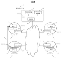
本発明における接続制御システムの構成を図1に示す。該システムにおいてネットワーク1(1)に属する端末1(10)、ネットワーク2(2)に属する端末2(20)、ネットワーク3(3)に属する端末3(30)、ネットワーク4(4)に属する端末4(40)は、LAN(50010)によりゲートウェイ1(15)、ゲートウェイ2(25)、ゲートウェイ3(35)、ゲートウェイ4(45)と接続し、これらを通じて、接続制御システム(5)に接続している。接続制御システム(5)は、端末間の通信を制御する接続制御装置(52)、利用者の認証を行う認証装置(54)、迂回路接続の際に必要となる接続用アドレスを生成するアドレス管理装置(56)を備える。ここで、ネットワーク1(1)からネットワーク3(3)への通信は許可されていない。しかし、ネットワーク1(1)からネットワーク2(2)、ネットワーク2(2)からネットワーク3(3)への通信はそれぞれ許可されている。 The configuration of the connection control system in the present invention is shown in FIG. In this system, terminal 1 (10) belonging to network 1 (1), terminal 2 (20) belonging to network 2 (2), terminal 3 (30) belonging to network 3 (3), and terminal belonging to network 4 (4) 4 (40) is connected to the gateway 1 (15), the gateway 2 (25), the gateway 3 (35), and the gateway 4 (45) through the LAN (50010), and is connected to the connection control system (5) through these. ing. The connection control system (5) includes a connection control device (52) for controlling communication between terminals, an authentication device (54) for authenticating a user, and an address for generating a connection address necessary for a detour connection. A management device (56) is provided. Here, communication from the network 1 (1) to the network 3 (3) is not permitted. However, communication from the network 1 (1) to the network 2 (2) and from the network 2 (2) to the network 3 (3) is permitted.
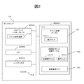
次に、接続制御システム(5)を構成する個々の要素の機能ブロックを示す。図2はゲートウェイ1(15)の構成である。接続制御装置が端末の接続を制御するために、接続制御装置と接続した図1中の他のゲートウェイ2〜4(25、35、45)も同様の構成を持つ。
ゲートウェイ1(15)は、ネットワークインターフェース(50000)を通じて外部と通信を行う。ゲートウェイ1(15)はさらにCPU(50002)、ハードディスク(50004)、メモリ(50008)を備え、これらはバス(50006)により相互にデータを送受信する。これらのハードウェア構成において、ゲートウェイ1(15)は端末からのパケットを受信して、宛先アドレスへ送信するパケット送受信部(110)をネットワークインターフェース(50000)に、接続を許可された端末の実アドレス(12010)を登録するアドレス登録テーブル(120)、迂回路接続の際に使用する迂回路アドレス(13010)と実アドレス(13020)の組を登録する迂回路アドレス登録テーブル(130)、通信状態を監視する通信監視タイマ(140)をメモリ(50008)上に備える。
Next, functional blocks of individual elements constituting the connection control system (5) are shown. FIG. 2 shows the configuration of the gateway 1 (15). In order for the connection control device to control the connection of the terminal, the
The gateway 1 (15) communicates with the outside through the network interface (50000). The gateway 1 (15) further includes a CPU (50002), a hard disk (50004), and a memory (50008), which exchange data with each other via a bus (50006). In these hardware configurations, the gateway 1 (15) receives a packet from the terminal, and transmits the packet transmission / reception unit (110) for transmitting to the destination address to the network interface (50000), and the real address of the terminal permitted to connect. Address registration table (120) for registering (12010), detour address registration table (130) for registering a pair of detour address (13010) and real address (13020) used for detour connection, and communication status A communication monitoring timer (140) for monitoring is provided on the memory (50008).
実アドレスは端末のネットワークインターフェースに割り当てられているアドレスであり、接続元端末と接続先端末の通信が許可されている場合はこのアドレスを用いて通信を行う。迂回路接続とは接続元端末と接続先端末の通信ができない場合に、接続許可のあるネットワークを経由した通信経路を迂回路として用いることで端末間の接続を制御することを指す。迂回路アドレスは迂回路接続において通信を行う場合にアドレス管理装置が端末に割り当てるアドレスである。
図3は接続制御装置(52)の構成である。接続制御装置(52)は外部と通信するためのネットワークインターフェース(50000)と、CPU(50002)、ハードディスク(50004)、バス(50006)、メモリ(50008)を基本ハード構成として備える。さらに、接続制御装置(52)は端末からのパケットを受信、あるいは送信するためのパケット送受信部(520)、接続制御システム(5)内の他の装置に処理を依頼するためのメッセージを送信したり、他の装置の処理結果をメッセージとして受信するためのメッセージ送受信部(522)をネットワークインターフェース(50000)に、端末からの接続要求に対して送信元端末のアドレスと送信先端末のアドレスから接続許可を判定するための情報を含む接続許可データベース(524)をハードディスク(50004)に、接続制御対象のユーザの状態を管理するユーザ状態管理部(526)、通信状態を監視する通信監視タイマ(528)をメモリ(50008)上で動作する接続制御プログラム(52000)の接続制御機能(52002)の一部として備える。ここで、メッセージとはシステム内の各装置間で交換されるパケットを指す。
The real address is an address assigned to the network interface of the terminal. When communication between the connection source terminal and the connection destination terminal is permitted, communication is performed using this address. Detour connection refers to controlling connection between terminals by using a communication path via a network with connection permission as a detour when communication between a connection source terminal and a connection destination terminal is not possible. The detour address is an address assigned to the terminal by the address management device when communication is performed in the detour connection.
FIG. 3 shows the configuration of the connection control device (52). The connection control device (52) includes a network interface (50000) for communicating with the outside, a CPU (50002), a hard disk (50004), a bus (50006), and a memory (50008) as basic hardware configurations. Further, the connection control device (52) transmits a message for requesting processing to the packet transmission / reception unit (520) for receiving or transmitting a packet from the terminal and other devices in the connection control system (5). In addition, a message transmission / reception unit (522) for receiving processing results of other devices as a message is connected to the network interface (50000) from a source terminal address and a destination terminal address in response to a connection request from the terminal. A connection permission database (524) including information for determining permission is stored in the hard disk (50004), a user state management unit (526) that manages the state of the user to be connected, and a communication monitoring timer (528) that monitors the communication state. ) In the connection control program (52000) that operates on the memory (50008) Provided as part of (52002). Here, the message refers to a packet exchanged between each device in the system.
図4は接続許可データベース(524)の詳細である。接続許可データベース(524)は接続が許可されているネットワーク間の関係を保持するものであり、接続元ネットワーク(5242)、接続先ネットワーク(5244)と、迂回路として使用可能かどうかを示す迂回路判定フラグ(5246)を含む。迂回路判定フラグ(5246)が真の時は、この通信路を迂回路として用いることが可能である。 FIG. 4 shows details of the connection permission database (524). The connection permission database (524) holds a relationship between networks to which connection is permitted. The connection source network (5242), the connection destination network (5244), and a detour indicating whether or not the detour can be used. A determination flag (5246) is included. When the detour determination flag (5246) is true, this communication path can be used as a detour.
図5はユーザ状態管理部(526)の詳細である。図5では一つのデータレコードのみ例示している。ユーザ状態管理部は接続制御中のユーザの状態を管理する機能ブロックであり、ユーザ名(5260)、端末アドレス(5261)、接続元ネットワーク(5262)、接続先ネットワーク(5264)、迂回路判定フラグ(5266)、認証判定フラグ(5268)、迂回路アドレス1(5270)、迂回路アドレスN(5272)を含む。迂回路判定フラグ(5266) は、対象ユーザが迂回路を使用中の場合に真となる。認証判定フラグ(5268)は、接続元ネットワークから接続先ネットワークへ通信する際のユーザ認証が完了済の場合に真となる。 FIG. 5 shows details of the user status management unit (526). FIG. 5 illustrates only one data record. The user status management unit is a functional block that manages the status of the user under connection control, and includes a user name (5260), a terminal address (5261), a connection source network (5262), a connection destination network (5264), and a detour determination flag. (5266), authentication determination flag (5268), detour address 1 (5270), and detour address N (5272). The detour determination flag (5266) is true when the target user is using the detour. The authentication determination flag (5268) is true when user authentication is completed when communicating from the connection source network to the connection destination network.
図6は認証装置(54)の構成である。認証装置(54)は外部と通信するためのネットワークインターフェース(50000)と、CPU(50002)、ハードディスク(50004)、バス(50006)、メモリ(50008)を基本ハード構成として備える。さらに、認証装置(54)はメッセージ送受信部(540)をネットワークインターフェース(50000)に、認証データベース(542)をハードディスク(50004)上に備え、メモリ(50008)上で動作する認証プログラム(54000)の認証機能(54002)の一部として通信監視タイマ(544)を備える。 FIG. 6 shows the configuration of the authentication device (54). The authentication device (54) includes a network interface (50000) for communicating with the outside, a CPU (50002), a hard disk (50004), a bus (50006), and a memory (50008) as basic hardware configurations. Further, the authentication device (54) includes a message transmission / reception unit (540) in the network interface (50000), an authentication database (542) on the hard disk (50004), and an authentication program (54000) operating on the memory (50008). A communication monitoring timer (544) is provided as a part of the authentication function (54002).
図7は認証データベース(542)の詳細である。図7では一つのデータレコードのみ例示している。迂回路接続を行う場合には複数の通信経路を経由して通信を行うが、その際認証は個々の通信経路ごとに行なう。認証データベース(542)は認証対象のユーザ名(5420)、接続元ネットワーク(5422)、接続先ネットワーク(5424)、パスワード(5426)を含む。 FIG. 7 shows details of the authentication database (542). FIG. 7 illustrates only one data record. When performing detour connection, communication is performed via a plurality of communication paths. At this time, authentication is performed for each communication path. The authentication database (542) includes a user name (5420) to be authenticated, a connection source network (5422), a connection destination network (5424), and a password (5426).
図8はアドレス管理装置(56)の構成である。アドレス管理装置(56)は外部と通信するためのネットワークインターフェース(50000)と、CPU(50002)、ハードディスク(50004)、バス(50006)、メモリ(50008)を基本ハード構成として備える。さらに、アドレス管理装置(56)はメッセージ送受信部(560)をネットワークインターフェース(50000)に、迂回路接続に用いるアドレスを生成するアドレス生成部(562)、アドレス生成時に必要な情報を管理するネットワーク情報管理部(564)、通信状態を監視する通信監視タイマ(566)をメモリ(50008)上で動作するアドレス管理プログラム(56000)の接続制御機能(56002)の一部として備える。 FIG. 8 shows the configuration of the address management device (56). The address management device (56) includes a network interface (50000) for communicating with the outside, a CPU (50002), a hard disk (50004), a bus (50006), and a memory (50008) as basic hardware configurations. Further, the address management device (56) uses the message transmission / reception unit (560) as the network interface (50000), the address generation unit (562) that generates an address used for the detour connection, and the network information that manages information necessary for address generation. The management unit (564) includes a communication monitoring timer (566) for monitoring the communication state as part of the connection control function (56002) of the address management program (56000) operating on the memory (50008).
図9はネットワーク情報管理部(564)の詳細である。本発明における接続制御システムでは、通信プロトコルにIPv6を想定している。従って、迂回路用のアドレス生成にはネットワークを識別する識別子(5640)とネットワーク内で用いられているネットワーク接頭辞(5642)が必要である。IPv4を用いる場合には、アドレスの生成にはネットワーク接頭辞(5642)は必要ない。代わりに、ネットワーク内の端末のアドレスを管理し、未使用のアドレスを迂回路用のアドレスとして用いる必要がある。IPv4におけるネットワーク情報管理部(564)を図26に示す。ネットワーク情報管理部(564)はネットワーク識別子(5640)とアドレス管理データベース(5644)を備える。 FIG. 9 shows details of the network information management unit (564). The connection control system according to the present invention assumes IPv6 as a communication protocol. Therefore, to generate an address for a detour, an identifier (5640) for identifying the network and a network prefix (5642) used in the network are required. When using IPv4, the network prefix (5642) is not required for address generation. Instead, it is necessary to manage the addresses of terminals in the network and use unused addresses as detour addresses. The network information management unit (564) in IPv4 is shown in FIG. The network information management unit (564) includes a network identifier (5640) and an address management database (5644).
次に、該システムの動作をシーケンスを用いて詳述する。図10は接続制御システム(5)の基本シーケンスを示している。また、このシーケンスで用いられるパケットの内容を図19に示す。前述したように、接続制御システム(5)においてはネットワーク1(1)からネットワーク2(2)、ネットワーク2(2)からネットワーク3(3)、ネットワーク3(3)からネットワーク4(4)、への接続が許可されており、全ての接続が迂回路として使用可能であるものと仮定し、ネットワーク1(1)に属する端末1(10)がネットワーク2(2)に属する端末2(20)と通信する場合を考える。通信を始めるにあたり、端末1(10)はネットワーク1(1)からネットワーク2(2)への接続要求(1000)をゲートウェイ1(15)を通じて送信する。以後特別な記述がない限り端末から接続制御装置(52)への通信はゲートウェイを経由するものとする。接続要求(1000)の内容を図19に示す。接続要求(1000)は送信元IP(2300)、宛先IP(2302)、パケット種別(接続要求)(2304)、接続元ネットワーク(2306)、接続先ネットワーク(2308)、ユーザ名(2310)を情報として含む。接続要求(1000)を受信した接続制御装置(52)は、要求された接続が許可されているかどうかを接続許可データベース(524)に問い合わせる。接続許可データベース(524)は接続要求(1000)の接続元ネットワーク(2306)とデータベース中の接続元ネットワーク(5242)、接続要求(1000)の接続先ネットワーク(2308)とデータベース中の接続先ネットワーク(5244)を比較し、要求された接続が許可されているかどうかを判定する。次に接続制御装置(52)はユーザ状態管理部(526)に、該ユーザの認証が完了しているかどうかを問い合わせる。ユーザ状態管理部(526)に該ユーザのエントリが存在しない場合には、接続制御装置(52)は該ユーザのエントリを生成し、端末1(10)に認証要求(1003)を送信する。図19に認証要求(1003)の内容を示す。認証要求(1003)は送信元IP(2700)、宛先IP(2702)、パケット種別(認証要求)(2704)、接続元ネットワーク(2706)、接続先ネットワーク(2708)、ユーザ名(2710)を情報として含む。該ユーザのエントリが存在する場合には、ユーザ状態管理部(526)はエントリの認証判定フラグ(5268)を調べ、偽の場合には端末1(10)に認証要求(1003)を送信する。端末1(10)はこれを受け、認証情報(1006)を接続制御装置(52)に送信する。認証情報(1006)の内容を図19に示す。認証情報(1006)は送信元IP(2500)、宛先IP(2502)、パケット種別(認証情報)(2504)、接続元ネットワーク(2506)、接続先ネットワーク(2508)、ユーザ名(2510)、パスワード(2512)を含む。認証情報(1006)を受信した接続制御装置(52)は、認証装置(54)に認証依頼(1009)を送信して認証を依頼する。認証依頼(1009)の内容を図19に示す。認証依頼(1009)はメッセージ種別(認証依頼)(4300)、接続元ネットワーク(4302)、接続先ネットワーク(4304)、ユーザ名(4306)、パスワード(4308)を含む。認証依頼(1009)中の接続元ネットワーク(4302)、接続先ネットワーク(4304)、ユーザ名(4306)、パスワード(4308)の値は、認証情報(1006)の接続元ネットワーク(2506)、接続先ネットワーク(2508)、ユーザ名(2510)、パスワード(2512)から取得する。認証依頼(1009)を受信した認証装置(54)は、認証の成否を認証データベース(542)に問い合わせる。認証装置(54)は認証依頼(1009)中の接続元ネットワーク(4302)、接続先ネットワーク(4304)、ユーザ名(4306)を用いて認証データベース(542)から対応するデータレコードを検索し、認証依頼(1009)中のパスワード(4308)とデータレコード中のパスワード(5426)を比較する。パスワードが一致する場合には認証の完了を接続制御装置(52)に通知する。これは認証完了(1012)を送信することで行われる。認証完了(1012)を受けた接続制御装置(52)は、認証完了通知(1015)を端末1(10)に送信する。この時点で認証が完了するため、接続制御装置(52)はユーザ状態管理部(526)の認証要求(1003)を送信したユーザの認証判定フラグ(5268)を真に、迂回路判定フラグ(5266)を偽に設定する。認証が完了した後に、接続制御装置(52)はゲートウェイ1(15)に認証が完了したユーザのアドレス登録(1016)を行う。アドレス登録(1016)の内容を図19に示す。アドレス登録(1016)は送信元IP(5000)、宛先IP(5002)、パケット種別(アドレス登録)(5004)、実アドレス(5006)を含む。ゲートウェイ1(15)は実アドレス(5006)をアドレス登録テーブル(120)に登録する。 Next, the operation of the system will be described in detail using a sequence. FIG. 10 shows a basic sequence of the connection control system (5). FIG. 19 shows the contents of the packet used in this sequence. As described above, in the connection control system (5), the network 1 (1) to the network 2 (2), the network 2 (2) to the network 3 (3), and the network 3 (3) to the network 4 (4). And the terminal 1 (10) belonging to the network 1 (1) is assumed to be connected to the terminal 2 (20) belonging to the network 2 (2). Consider the case of communication. In starting communication, the terminal 1 (10) transmits a connection request (1000) from the network 1 (1) to the network 2 (2) through the gateway 1 (15). Hereinafter, unless otherwise specified, communication from the terminal to the connection control device (52) is assumed to go through the gateway. The contents of the connection request (1000) are shown in FIG. The connection request (1000) is information on the source IP (2300), destination IP (2302), packet type (connection request) (2304), connection source network (2306), connection destination network (2308), and user name (2310). Include as. The connection control device (52) that has received the connection request (1000) inquires of the connection permission database (524) whether or not the requested connection is permitted. The connection permission database (524) includes a connection source network (2306) of the connection request (1000), a connection source network (5242) in the database, a connection destination network (2308) of the connection request (1000), and a connection destination network ( 5244) to determine if the requested connection is permitted. Next, the connection control device (52) inquires of the user state management unit (526) whether or not the authentication of the user has been completed. If the user entry does not exist in the user status management unit (526), the connection control device (52) generates the user entry and transmits an authentication request (1003) to the terminal 1 (10). FIG. 19 shows the contents of the authentication request (1003). The authentication request (1003) is a source IP (2700), destination IP (2702), packet type (authentication request) (2704), connection source network (2706), connection destination network (2708), and user name (2710). Include as. When the user entry exists, the user state management unit (526) checks the authentication determination flag (5268) of the entry, and when false, transmits an authentication request (1003) to the terminal 1 (10). In response to this, the terminal 1 (10) transmits authentication information (1006) to the connection control device (52). The contents of the authentication information (1006) are shown in FIG. Authentication information (1006) includes source IP (2500), destination IP (2502), packet type (authentication information) (2504), connection source network (2506), connection destination network (2508), user name (2510), and password. (2512). The connection control device (52) that has received the authentication information (1006) sends an authentication request (1009) to the authentication device (54) to request authentication. The contents of the authentication request (1009) are shown in FIG. The authentication request (1009) includes a message type (authentication request) (4300), a connection source network (4302), a connection destination network (4304), a user name (4306), and a password (4308). The values of the connection source network (4302), the connection destination network (4304), the user name (4306), and the password (4308) in the authentication request (1009) are the connection source network (2506) and the connection destination of the authentication information (1006). Obtained from the network (2508), user name (2510), and password (2512). Upon receiving the authentication request (1009), the authentication device (54) inquires of the authentication database (542) whether the authentication is successful. The authentication device (54) retrieves the corresponding data record from the authentication database (542) using the connection source network (4302), the connection destination network (4304), and the user name (4306) in the authentication request (1009), and performs authentication. The password (4308) in the request (1009) is compared with the password (5426) in the data record. If the passwords match, the completion of authentication is notified to the connection control device (52). This is done by sending an authentication completion (1012). Upon receiving the authentication completion (1012), the connection control device (52) transmits an authentication completion notification (1015) to the terminal 1 (10). Since the authentication is completed at this time, the connection control device (52) sets the authentication determination flag (5268) of the user who transmitted the authentication request (1003) of the user state management unit (526) to true, and the detour determination flag (5266). ) Is set to false. After the authentication is completed, the connection control device (52) registers the address of the authenticated user (1016) in the gateway 1 (15). The contents of address registration (1016) are shown in FIG. Address registration (1016) includes source IP (5000), destination IP (5002), packet type (address registration) (5004), and real address (5006). Gateway 1 (15) registers the real address (5006) in the address registration table (120).
ユーザ状態管理部(526)内のユーザ状態を更新した後、接続制御装置(52)は接続許可通知(1018)を端末1(10)に送信する。図19に接続許可通知(1018)の内容を示す。接続許可通知(1018)は送信元IP(3300)、宛先IP(3302)、パケット種別(接続許可通知)(3304)、接続元ネットワーク(3306)、接続先ネットワーク(3308)、ユーザ名(3310)を情報として含む。接続許可通知(1018)を受信した端末1(10)はこの時点で端末2(20)との通信が可能になり、ゲートウェイ1(15)、ゲートウェイ2(25)を経由して端末2との通信を開始する(1021)。
端末1(10)は通信を終了する際に接続制御装置(52)に対して接続終了(1024)を送信する。接続終了(1024)を受信した接続制御装置(52)は、ユーザ状態管理部(526)の該接続終了(1024)を送信したユーザに対応するエントリを削除し、端末1(10)に接続終了確認(1027)を送信する。最後に接続管理装置(52)はゲートウェイ1(15)にアドレス削除(1030)を送信する。アドレス削除(1030)の内容を図19に示す。アドレス削除(1030)は送信元IP(5100)、宛先IP(5102)、パケット種別(アドレス削除)(5104)、実アドレス(5106)を含む。ゲートウェイ1(15)は実アドレス(5106)をアドレス登録テーブル(120)から削除する。以後端末1(10)が接続制御装置(52)を経由して端末2(20)と通信するには、再度接続要求(1000)を送信して認証を経なければならない。以上で通常の接続処理が完了する。
After updating the user status in the user status management unit (526), the connection control device (52) transmits a connection permission notification (1018) to the terminal 1 (10). FIG. 19 shows the contents of the connection permission notification (1018). The connection permission notification (1018) includes a source IP (3300), a destination IP (3302), a packet type (connection permission notification) (3304), a connection source network (3306), a connection destination network (3308), and a user name (3310). Is included as information. The terminal 1 (10) that has received the connection permission notification (1018) can communicate with the terminal 2 (20) at this time, and communicates with the
The terminal 1 (10) transmits a connection end (1024) to the connection control device (52) when the communication is ended. Upon receiving the connection termination (1024), the connection control device (52) deletes the entry corresponding to the user who transmitted the connection termination (1024) in the user state management unit (526), and terminates the connection to the terminal 1 (10). Confirmation (1027) is transmitted. Finally, the connection management device (52) transmits an address deletion (1030) to the gateway 1 (15). The contents of address deletion (1030) are shown in FIG. The address deletion (1030) includes a source IP (5100), a destination IP (5102), a packet type (address deletion) (5104), and a real address (5106). Gateway 1 (15) deletes the real address (5106) from the address registration table (120). Thereafter, in order for the terminal 1 (10) to communicate with the terminal 2 (20) via the connection control device (52), the connection request (1000) must be transmitted again to undergo authentication. This completes the normal connection process.
次に、接続許可のないネットワーク間の通信について考える。図12はネットワーク1(1)からネットワーク3(3)への通信を要求した場合の処理である。図1においてネットワーク2(2)に属していた端末2(20)がネットワーク1(1)に移動して(9)端末1(10)となり、ネットワーク3(3)に属する端末3(30)と通信する場合がこれに相当する。 Next, consider communication between networks without connection permission. FIG. 12 shows processing when a request for communication from the network 1 (1) to the network 3 (3) is made. In FIG. 1, the terminal 2 (20) belonging to the network 2 (2) moves to the network 1 (1) and becomes (9) the terminal 1 (10), and the terminal 3 (30) belonging to the network 3 (3) This is the case when communicating.
本発明におけるシステムでは迂回路を用いた通信を行うことで、接続許可のないネットワーク間では接続できないという問題を解決する。迂回路は接続許可がないネットワーク間の通信を実現するための通信経路である。図1において、ネットワーク1(1)からネットワーク3(3)への接続許可は存在しないが、ネットワーク1(1)からネットワーク2(2)、ネットワーク2(2)からネットワーク3(3)への接続許可は存在する。そこで、ネットワーク(1)からネットワーク(3)への通信を、ネットワーク2(2)を経由する迂回路を経ることで実現する。この時、接続許可を満たすアドレスを端末が持つことが必要となる。端末1がネットワーク1(1)からネットワーク2(2)を経由してネットワーク3(3)に属する端末3(30)と通信するには、ネットワーク2(2)からネットワーク(3)へ通信する必要があるが、接続許可を満たすためには端末1(10)がネットワーク2(2)におけるアドレスを持つ必要がある。ところが端末1(10)の持つアドレスはネットワーク(1)に属するため、そのままではネットワーク2(2)からネットワーク3(3)へ通信できない。そこで、アドレス管理装置(56)は端末1(10)に迂回路アドレスとしてネットワーク2(2)でのアドレスを付与する。ネットワーク2(2)における通信用のアドレスを端末に割り当てることで、ネットワーク2(2)を経由した、すなわち迂回路を用いた通信が可能になる。
The system according to the present invention solves the problem that it is not possible to connect between networks without connection permission by performing communication using a detour. The detour is a communication path for realizing communication between networks without connection permission. In FIG. 1, there is no connection permission from network 1 (1) to network 3 (3), but connection from network 1 (1) to network 2 (2) and from network 2 (2) to network 3 (3). Permission exists. Therefore, communication from the network (1) to the network (3) is realized through a detour route via the network 2 (2). At this time, the terminal needs to have an address satisfying the connection permission. In order for the
図11に迂回路を用いた通信シーケンスを示す。また、このシーケンスで用いられるパケットの内容を図20、図21に示す。端末1(10)は接続制御装置(52)に接続要求(1200)を送信する。接続要求(1200)を受信した接続制御装置(52)は、要求された接続が許可されているかどうかを接続許可データベース(524)に問い合わせる。ネットワーク1(1)からネットワーク3(3)への通信は許可されていないため、接続制御装置(52)は接続不許可通知(1203)を端末1(10)に送信する。接続不許可通知(1203)の内容を図20に示す。接続不許可通知(1203)は送信元IP(3500)、宛先IP(3502)、パケット種別(接続許可通知)(3504)、接続元ネットワーク(3506)、接続先ネットワーク(3508)、ユーザ名(3510)を情報として含む。接続不許可通知(1203)を受信した端末(10)はネットワーク1(1)からネットワーク3(3)へ直接接続できないことを知り、接続制御装置(52)に迂回路による接続を要求するため、迂回路接続要求(1206)を送信する。迂回路接続要求の内容を図20に示す。迂回路接続要求(1206)は送信元IP(2400)、宛先IP(2402)、パケット種別(迂回路接続要求)(2404)、接続元ネットワーク(2406)、接続先ネットワーク(2408)、ユーザ名(2410)を情報として含む。この例では接続元ネットワーク(2406)にネットワーク1(1)、接続先ネットワークにネットワーク3(3)を指定する。迂回路接続要求(1206)を受信した接続制御装置(52)は要求された迂回路が存在するかどうかを接続許可データベース(524)に問い合わせる。接続許可データベース(524)は迂回路接続要求(1200)の接続元ネットワーク(2406)と接続先ネットワーク(2408) を用いて迂回路を検索する。接続許可データベース(524)は、接続元ネットワークから接続先ネットワークを結ぶ経路が、自身が管理する接続許可のあるネットワークの連結で構築できる場合に迂回可能と判断する。ネットワークの連結とは、ある接続許可1の接続先ネットワークと別の接続許可2の接続元ネットワークが一致する場合に、接続許可1の接続元ネットワークを接続元ネットワークに、接続許可2の接続先ネットワークを接続先ネットワークにした新しい接続許可3を生成することを指す。例えば、ネットワーク1(1)からネットワーク3(3)については、接続許可データベース中の接続許可のうちネットワーク1(1)からネットワーク2(2)、ネットワーク2(2)からネットワーク3(3)という経路が存在し、ネットワークの連結による迂回が可能である。可能と判断したら、接続制御装置(52)はユーザ状態管理部(526)に、迂回路接続要求(1206)を送信したユーザの認証が完了しているかどうかを問い合わせる。この時点ではユーザ状態管理部(526)には該ユーザのエントリはまだ生成されていないので、接続制御装置(52)は該ユーザのエントリを生成し、端末1(10)に迂回路認証要求(1209)を送信する。図20に迂回路認証要求(1209)の内容を示す。迂回路認証要求(1209) は送信元IP(2800)、宛先IP(2802)、パケット種別(迂回路認証要求) (2804)、接続元ネットワーク(2806)、経由ネットワーク1(2808)、経由ネットワークN(2810)、接続先ネットワーク(2812)、ユーザ名(2814)を情報として含む。NはN番目の経由ネットワークを表わす。この例ではネットワーク2(2)を経由するので、接続元ネットワーク(2806)にネットワーク1(1)、経由ネットワーク1(2808)にネットワーク2(2)、接続先ネットワーク(2812)にネットワーク3(3)を指定する。ネットワークの指定には各ネットワークが識別できる情報を用いる。例えば各ネットワークに属するゲートウェイのアドレスや、アドレス管理装置(56)のネットワーク情報管理部(564)が持つネットワーク識別子(5640)等がこれに相当する。迂回路認証要求(1209)を受信した端末1(10)は迂回路認証情報(1212)を接続制御装置(52)に送信する。迂回路認証情報(1212)は経由する全ての迂回路に必要な認証情報を含む必要がある。迂回路認証情報(1212)の内容を図20に示す。迂回路認証情報(1212)は送信元IP(2600)、宛先IP(2602)、パケット種別(迂回路認証情報) (2604)、接続元ネットワーク(2606)、経由ネットワーク1(2608)、経由ネットワークN(2610)、接続先ネットワーク(2612)、ユーザ名(2614)、パスワード1(2616)、パスワードN+1(2618)を含む。パスワードIは経由ネットワークI−1から経由ネットワークIへ接続する際に必要なパスワードを表す。経由ネットワーク0は接続元ネットワーク(2608)、経由ネットワークN+1は接続先ネットワーク(2610)に対応する。迂回路認証情報(1212)を受信した接続制御装置(52)は、認証装置(54)に迂回路認証依頼(1215)を送信して認証を依頼する。迂回路認証依頼(1215)の内容を図20に示す。迂回路認証依頼(1215) はメッセージ種別(迂回路認証依頼)(4400)、接続元ネットワーク(4402)、経由ネットワーク1(4404)、経由ネットワークN(4406)、接続先ネットワーク(4408)、ユーザ名(4410)、パスワード1(4412)、パスワードN+1(4414)を含む。経由ネットワークとパスワードの添字の関係は迂回路認証情報(1212)と同様である。迂回路認証依頼(1215)を受信した認証装置(54)は、認証の成否を認証データベース(542)に問い合わせる。認証装置(54)は迂回路認証依頼(1215)中の全てのパスワードに対して経由ネットワークI−1、経由ネットワークI、ユーザ名(4410)、パスワードIを、認証データベース(542)の接続元ネットワーク(5422)、接続先ネットワーク(5424)、ユーザ名(5420)、パスワード(5426)とそれぞれ比較し、全てのパスワードに対してデータレコードが存在する場合に認証の完了を接続制御装置(52)に通知する。これは迂回路認証完了(1218)を送信することで行われる。迂回路認証完了(1218)の内容を図20に示す。迂回路認証完了(1218)はメッセージ種別(迂回路認証完了)(3900)、接続元ネットワーク(3902)、経由ネットワーク1(3904)、経由ネットワークN(3906)、接続先ネットワーク(3908)、ユーザ名(3910)を情報として含む。迂回路認証完了(1218)を受けた接続制御装置(52)は、迂回路認証完了通知(1221)を端末1(10)に送信する。迂回路認証完了通知(1221)の内容を図21に示す。迂回路認証完了通知(1221)は送信元IP(3000)、宛先IP(3002)、パケット種別(迂回路認証完了通知) (3004)、接続元ネットワーク(3006)、経由ネットワーク1(3008)、経由ネットワークN(3010)、接続先ネットワーク(3012)、ユーザ名(3014)を情報として含む。この時点で認証が完了するため、接続制御装置(52)はユーザ状態管理部(526)の該ユーザの認証判定フラグ(5268)と迂回路判定フラグ(5266)を真に設定する。先述したように、迂回路接続の際にはそれぞれの経由ネットワークに対して端末の迂回路アドレスを生成する必要がある。接続制御装置(52)は迂回路アドレスの生成をアドレス管理装置(56)に依頼する。この処理はアドレス生成依頼(1224)をアドレス管理装置(56)に送信することで行う。アドレス生成依頼(1224)の内容を図21に示す。アドレス生成依頼(1224)はメッセージ種別(アドレス生成依頼)(4500)、端末MACアドレス(4502)、経由ネットワーク1(4504)、経由ネットワークN(4506)を情報として含む。端末のMACアドレスは、ユーザ状態管理部(526)の端末アドレス(5261)から抽出可能であり、アドレス生成を依頼する際にアドレス管理装置(56)にこれを送信する。アドレス生成依頼(1224)を受信したアドレス管理装置(56)はアドレス生成処理を行う。アドレスの生成は受信したアドレス生成依頼(1224)中の端末MACアドレス(4502)と、経由ネットワークIのゲートウェイのアドレスから検出したネットワークプレフィックスネットワーク接頭辞(5642)を用いて行う。IPv4の場合はアドレス管理データベース(5644)を検索して未使用のアドレスを生成アドレスとして用いる。アドレス管理装置(56)は生成したアドレスをアドレス生成完了(1227)を用いて接続制御装置(52)に通知する。アドレス生成完了(1227)の内容を図21に示す。アドレス生成完了(1227)はメッセージ種別(アドレス生成完了)(4200)、端末MACアドレス(4202)、生成アドレス1(4204)、生成アドレスN(4206)を情報として含む。生成アドレスIはアドレス生成依頼(1224)の経由ネットワークIに対応したアドレスである。アドレス生成完了(1227)を受信した接続制御装置(52)はアドレスをユーザ状態管理部(526)の迂回路アドレスに登録する。ここではネットワーク2(2)用の迂回路アドレスを迂回路アドレス1(5270)として登録する。次に、アドレス生成通知(1230)を端末1(10)に送信して生成したアドレスを通知する。アドレス生成通知(1230)の内容を図21に示す。アドレス生成通知(1230)は送信元IP(3700)、宛先IP(3702)、パケット種別(アドレス生成通知)(3704)、端末アドレス(3706)、生成アドレス1(3708)、生成アドレスN(3710)を情報として含む。端末1(10)はネットワーク2(2)用のアドレスを受信し、以降の通信に用いる。この処理については後述する。端末1(10)へのアドレスの通知を終えた接続制御装置(52)は、迂回路接続を可能にするために通信路上に存在するゲートウェイに対してアドレスの登録を行う。通信路に存在するゲートウェイにはゲートウェイ1(15)、ゲートウェイ2(25)、ゲートウェイ3(35)があるが、ここではゲートウェイ1(15)に接続許可のために必要なアドレスの登録、ゲートウェイ2(25)に迂回路通信のために必要なアドレスの登録をそれぞれ行う。接続制御装置(52)はゲートウェイ1(15)にアドレス登録(1231)を送信する。ここで登録するアドレスは端末1(10)のアドレスであり、これはユーザ状態管理部(526)の端末アドレス(5261)に格納されている。次に接続制御装置(52)は迂回路アドレス登録(1232)をゲートウェイ2(25)に送信する。図21に迂回路アドレス登録(1232)の内容を示す。迂回路アドレス登録(1232)は送信元IP(5200)、宛先IP(5202)、パケット種別(迂回路アドレス登録)(5204)、迂回路アドレス(5206)、実アドレス(5208)を情報として含む。迂回路アドレス(5206)は接続先ネットワークに存在する端末が迂回路ネットワークに後続のパケットを送信するために必要なアドレスであり、この例ではネットワーク2(2)に対して生成したアドレスが該当する。実アドレス(5208)は経由ネットワークに存在するゲートウェイが後続のパケットを転送するために必要なアドレスであり、一つ前の経由ネットワークに対して生成したアドレスが該当する。つまり、ネットワークIを経由する場合、迂回路アドレスにはネットワークIに対して生成したアドレス、実アドレスにはネットワークI−1に対して生成したアドレスが該当する。なお、ネットワーク1は端末が属するネットワークである。ここでは迂回路アドレス(5206)にネットワーク2(2)用のアドレスを指定する。これはユーザ状態管理部(526)の迂回路アドレス1(5270)に格納されている。実アドレス(5208)
には端末1(10)のアドレスを指定する。これはユーザ状態管理部(526)の端末アドレス(5261)に格納されている。必要なアドレスの登録を終えた接続制御装置(52)は、端末1(10)に迂回路接続許可通知(1233)を送信する。迂回路接続許可通知(1233)の内容を図21に示す。迂回路接続許可通知(1233)は送信元IP(3400)、宛先IP(3402)、パケット種別(迂回路接続許可通知)(3404)、接続元ネットワーク(3406)、経由ネットワーク1(3408)、経由ネットワークN(3410)、接続先ネットワーク(3412)、ユーザ名(3414)を情報として含む。迂回路接続許可通知(1233)を受信した端末はゲートウェイ1(15)、ゲートウェイ2(25)、ゲートウェイ3(35)を経由して端末3(30)との通信を行う(1236)。
FIG. 11 shows a communication sequence using a detour. The contents of the packet used in this sequence are shown in FIGS. The terminal 1 (10) transmits a connection request (1200) to the connection control device (52). The connection control device (52) that has received the connection request (1200) inquires of the connection permission database (524) whether the requested connection is permitted. Since communication from the network 1 (1) to the network 3 (3) is not permitted, the connection control device (52) transmits a connection non-permission notification (1203) to the terminal 1 (10). The contents of the connection rejection notification (1203) are shown in FIG. The connection non-permission notification (1203) includes a source IP (3500), a destination IP (3502), a packet type (connection permission notification) (3504), a connection source network (3506), a connection destination network (3508), and a user name (3510). ) As information. The terminal (10) that has received the connection disapproval notice (1203) knows that it cannot connect directly to the network 3 (3) from the network 1 (1), and requests the connection control device (52) to connect by a detour. A detour connection request (1206) is transmitted. The contents of the detour connection request are shown in FIG. The detour connection request (1206) includes a source IP (2400), a destination IP (2402), a packet type (detour connection request) (2404), a connection source network (2406), a connection destination network (2408), a user name ( 2410) as information. In this example, the network 1 (1) is designated as the connection source network (2406), and the network 3 (3) is designated as the connection destination network. The connection control device (52) having received the detour connection request (1206) inquires of the connection permission database (524) whether the requested detour exists. The connection permission database (524) searches for a detour using the connection source network (2406) and the connection destination network (2408) of the detour connection request (1200). The connection permission database (524) determines that detouring is possible when the path connecting the connection source network to the connection destination network can be established by connecting networks with connection permission managed by itself. Network connection means that when a connection destination network of one
Is the address of the terminal 1 (10). This is stored in the terminal address (5261) of the user status management unit (526). The connection control device (52) that has completed the registration of the necessary address transmits a bypass connection permission notification (1233) to the terminal 1 (10). The contents of the bypass connection permission notification (1233) are shown in FIG. The detour connection permission notification (1233) includes the source IP (3400), the destination IP (3402), the packet type (detour connection permission notification) (3404), the connection source network (3406), the via network 1 (3408), The network N (3410), the connection destination network (3412), and the user name (3414) are included as information. The terminal that has received the detour connection permission notification (1233) communicates with the terminal 3 (30) via the gateway 1 (15), gateway 2 (25), and gateway 3 (35) (1236).
端末1(10)は通信を終了する際に接続制御装置(52)に対して接続終了(1239)を送信する。接続終了(1239)を受信した接続制御装置(52)は、ユーザ状態管理部(526)の該接続終了(1239)を送信したユーザに対応するエントリを削除し、端末1(10)に接続終了確認(1242)を送信する。最後に接続管理装置(52)はゲートウェイに登録したアドレスを削除するために、ゲートウェイ1(15)にアドレス削除(1245)を送信する。アドレス削除(1245)の内容は、図19に示したアドレス削除(1030)の内容と同様である。ゲートウェイ1(15)は実アドレス(5106)をアドレス登録テーブル(120)から削除し、以後端末1(10)が接続制御装置(52)を経由して端末3(30)と迂回路接続による通信をするには、再度迂回路接続要求(1206)を送信して認証を経なければならない。次に接続制御装置(52)はゲートウェイ2(25)に迂回路アドレス削除(1248)を送信する。迂回路アドレス削除(1248)の内容を図21に示す。迂回路アドレス削除(1248)は送信元IP(5300)、宛先IP(5302)、パケット種別(迂回路アドレス削除)(5304)、迂回路アドレス(5306)、実アドレス(5308)を情報として含む。以上で迂回路接続処理が完了する。 The terminal 1 (10) transmits a connection end (1239) to the connection control device (52) when the communication is ended. Upon receiving the connection end (1239), the connection control device (52) deletes the entry corresponding to the user who transmitted the connection end (1239) in the user state management unit (526) and ends the connection to the terminal 1 (10). Confirmation (1242) is transmitted. Finally, the connection management device (52) transmits an address deletion (1245) to the gateway 1 (15) in order to delete the address registered in the gateway. The contents of the address deletion (1245) are the same as the contents of the address deletion (1030) shown in FIG. The gateway 1 (15) deletes the real address (5106) from the address registration table (120), and then the terminal 1 (10) communicates with the terminal 3 (30) via the connection control device (52) via the detour connection. In order to do this, the detour connection request (1206) must be sent again for authentication. Next, the connection control device (52) transmits the detour address deletion (1248) to the gateway 2 (25). The contents of detour address deletion (1248) are shown in FIG. The detour address deletion (1248) includes the source IP (5300), destination IP (5302), packet type (deletion of detour address) (5304), detour address (5306), and real address (5308) as information. The detour connection process is thus completed.
次に、各機能ブロックの動作をフローチャートを用いて詳述する。
図12は接続制御装置(52)のフローチャートである。接続制御装置(52)はシステム起動時に処理を開始して(1300)メッセージ/パケット受信ループに入る(1301)。受信したメッセージが接続要求(1000)の場合(1302)、接続制御装置(52)は接続処理(1324)を行う。接続処理(1324)については後述する。受信したメッセージが迂回路接続要求(1206)の場合(1304)、接続制御装置(52)は迂回路接続処理(1326)を行う。迂回路接続処理(1326)については後述する。認証情報(1006)を受信した場合(1306)、接続制御装置(52)は認証装置(54)に認証を依頼する(1328)。迂回路認証情報(1212)を受信した場合(1308)、接続制御装置(52)は認証装置(54)に迂回路認証を依頼する(1330)。認証失敗を受信した場合(1310)、接続制御装置(52)は端末に認証失敗を通知する(1332)。認証失敗は認証装置(54)が認証に失敗したことを接続制御装置(52)に通知するメッセージである。迂回路認証失敗を受信した場合(1312)、接続制御装置(52)は端末に迂回路認証失敗を通知する(1334)。迂回路認証失敗は認証装置(54)が迂回路認証に失敗したことを接続制御装置(52)に通知するメッセージである。迂回路認証失敗の内容を図22に示す。迂回路認証失敗はメッセージ種別(迂回路認証失敗)(4100)、接続元ネットワーク(4102)、経由ネットワーク1(4104)、経由ネットワークN(4106)、接続先ネットワーク(4108)、ユーザ名(4110)を情報として含む。接続制御装置は端末に迂回路認証失敗通知を送信する。迂回路認証失敗通知の内容を図22に示す。迂回路認証失敗通知は送信元IP(3200)、宛先IP(3202)、パケット種別(迂回路認証失敗通知)(3204)、接続元ネットワーク(3206)、経由ネットワーク1(3208)、経由ネットワークN(3210)、接続先ネットワーク(3212)、ユーザ名(3214)を情報として含む。認証完了(1012)を受信した場合(1314)、接続制御装置(52)は認証完了通知(1015)を端末に送信して認証完了を通知し(1336)、ゲートウェイにアドレス登録(1030)を送信してアドレス登録テーブル(120)に端末のアドレスを登録し(1338)、接続許可通知(1018)を端末に送信して通信を開始させる(1340)。迂回路認証完了(1218)を受信した場合(1316)、接続制御装置(52)は迂回路認証完了通知(1221)を端末に送信して迂回路認証完了を通知し(1342)、アドレス管理装置にアドレス生成依頼(1224)を送信してアドレスの生成を依頼する(1344)。アドレス生成完了(1227)を受信した場合(1318)、接続制御装置(52)はアドレス生成通知(1230)を端末に送信し(1346)、端末のアドレスと生成した迂回路アドレスをアドレス登録(1231)、迂回路アドレス登録(1232)によりゲートウェイに登録し(1348)、迂回路接続許可通知(1233)を端末に送信する(1350)。端末から接続終了(1239)を受信した場合(1320)、接続制御装置(52)は接続終了確認(1242)を端末に送信し(1352)、アドレス削除(1245)、迂回路アドレス削除(1248)によりゲートウェイから該当するアドレスを削除する(1354)。パケット/メッセージ受信ループはシステム停止時に停止して(1322)、接続制御装置(52)は終了する(1399)。
Next, the operation of each functional block will be described in detail using a flowchart.
FIG. 12 is a flowchart of the connection control device (52). The connection control device (52) starts processing at system startup (1300) and enters a message / packet reception loop (1301). When the received message is a connection request (1000) (1302), the connection control device (52) performs a connection process (1324). The connection process (1324) will be described later. When the received message is a bypass connection request (1206) (1304), the connection control device (52) performs a bypass connection process (1326). The detour connection processing (1326) will be described later. When the authentication information (1006) is received (1306), the connection control device (52) requests the authentication device (54) for authentication (1328). When the detour authentication information (1212) is received (1308), the connection control device (52) requests the authentication device (54) for detour authentication (1330). When the authentication failure is received (1310), the connection control device (52) notifies the terminal of the authentication failure (1332). The authentication failure is a message notifying the connection control device (52) that the authentication device (54) has failed in authentication. When the detour authentication failure is received (1312), the connection control device (52) notifies the terminal of the detour authentication failure (1334). The detour authentication failure is a message that notifies the connection control device (52) that the authentication device (54) has failed in detour authentication. The contents of the detour authentication failure are shown in FIG. The detour authentication failure is message type (detour authentication failure) (4100), connection source network (4102), via network 1 (4104), via network N (4106), connection destination network (4108), user name (4110) Is included as information. The connection control device transmits a detour authentication failure notification to the terminal. The contents of the detour authentication failure notification are shown in FIG. The detour authentication failure notification includes a source IP (3200), a destination IP (3202), a packet type (detour authentication failure notification) (3204), a connection source network (3206), a via network 1 (3208), and a via network N ( 3210), a connection destination network (3212), and a user name (3214) as information. When the authentication completion (1012) is received (1314), the connection control device (52) sends an authentication completion notification (1015) to the terminal to notify the authentication completion (1336), and sends an address registration (1030) to the gateway. Then, the address of the terminal is registered in the address registration table (120) (1338), and a connection permission notification (1018) is transmitted to the terminal to start communication (1340). When the detour authentication completion (1218) is received (1316), the connection control device (52) sends a detour authentication completion notification (1221) to the terminal to notify the detour authentication completion (1342), and the address management device An address generation request (1224) is transmitted to the server to request an address generation (1344). When the address generation completion (1227) is received (1318), the connection control device (52) transmits an address generation notification (1230) to the terminal (1346), and registers the address of the terminal and the generated detour address (1231). ), Registration in the gateway by detour address registration (1232) (1348), and detour connection permission notification (1233) is transmitted to the terminal (1350). When connection termination (1239) is received from the terminal (1320), the connection control device (52) transmits a connection termination confirmation (1242) to the terminal (1352), address deletion (1245), and detour address deletion (1248). To delete the corresponding address from the gateway (1354). The packet / message reception loop is stopped when the system is stopped (1322), and the connection control device (52) is ended (1399).
次に接続処理の様子を図13に示す。接続処理が開始すると(1400)、最初に要求された接続が許可されているかどうかを把握するために、接続許可データベース(524)を検索する(1402)。対応するデータレコードが接続許可データベース(524)に存在しなければ、接続制御装置(52)は接続不許可通知(1203)を端末に送信して(1420)接続処理を終了する(1499)。データレコードが存在する場合はユーザ状態管理部(526)を検索して認証が完了しているかどうかを調べる(1404)。認証が完了していない場合は認証要求(1003)を端末に送信して(1422)接続処理を終了する(1499)。認証が完了している場合は接続許可通知(1018)を送信して(1406)接続処理を終了する(1499)。 Next, the state of the connection process is shown in FIG. When the connection process starts (1400), the connection permission database (524) is searched (1402) in order to grasp whether or not the connection requested first is permitted. If the corresponding data record does not exist in the connection permission database (524), the connection control device (52) transmits a connection non-permission notification (1203) to the terminal (1420) and ends the connection process (1499). If a data record exists, the user state management unit (526) is searched to check whether authentication is completed (1404). If the authentication is not completed, an authentication request (1003) is transmitted to the terminal (1422), and the connection process is terminated (1499). When the authentication is completed, a connection permission notification (1018) is transmitted (1406), and the connection process is terminated (1499).
次に迂回路接続処理の様子を図14に示す。迂回路接続処理が開始すると(1500)、最初に要求された迂回路が存在するかどうかを把握するために、接続許可データベース(524)を検索する(1502)。迂回路が接続許可データベース(524)から算出できない場合、接続制御装置(52)は迂回路接続不許可通知を端末に送信して(1520)接続処理を終了する(1599)。迂回路接続不許可通知の内容を図22に示す。迂回路接続不許可通知は送信元IP(3600)、宛先IP(3602)、パケット種別(迂回路接続許可通知)(3604)、接続元ネットワーク(3606)、接続先ネットワーク(3608)、ユーザ名(3610)を情報として含む。迂回路が存在する場合はユーザ状態管理部(526)を検索して認証が完了しているかどうかを調べる(1504)。認証が完了していない場合は迂回路認証要求(1209)を端末に送信して(1522)接続処理を終了する(1599)。認証が完了している場合はアドレスが生成済であるかどうかをユーザ状態管理部(526)に問い合わせる。アドレス生成判定は迂回路判定フラグ(5266)が真の場合に迂回路アドレス1(5270)が存在するかどうかによって行う。アドレスが未生成の場合、接続制御装置(52)はアドレス管理装置(56)にアドレス生成依頼(1224)を送信する(1524)。アドレスが生成済の場合は端末にアドレス生成通知(1230)を送信してアドレスの通知を行い(1508)、迂回路接続許可通知(1233)を送信して(1510)迂回路接続処理を終了する(1599)。 Next, the state of the detour connection processing is shown in FIG. When the detour connection processing starts (1500), the connection permission database (524) is searched (1502) in order to know whether or not the detour route requested first exists. When the detour cannot be calculated from the connection permission database (524), the connection control device (52) transmits a detour connection non-permission notice to the terminal (1520) and ends the connection process (1599). The contents of the bypass connection disapproval notice are shown in FIG. The detour connection disapproval notice includes the source IP (3600), destination IP (3602), packet type (detour connection permission notice) (3604), connection source network (3606), connection destination network (3608), user name ( 3610) as information. If a detour exists, the user state management unit (526) is searched to check whether authentication is completed (1504). If the authentication is not completed, a detour authentication request (1209) is transmitted to the terminal (1522), and the connection process is terminated (1599). When the authentication is completed, the user status management unit (526) is inquired whether the address has been generated. The address generation determination is performed based on whether or not the detour address 1 (5270) exists when the detour determination flag (5266) is true. When the address is not generated, the connection control device (52) transmits an address generation request (1224) to the address management device (56) (1524). If the address has been generated, an address generation notification (1230) is transmitted to the terminal to notify the address (1508), a detour connection permission notification (1233) is transmitted (1510), and the detour connection processing is terminated. (1599).
図15は認証装置(54)のフローチャートである。認証装置(54)はシステム起動時に処理を開始して(1600)メッセージ受信ループに入る(1601)。受信したメッセージが認証依頼(1009)の場合(1602)、認証装置(54)は認証処理を行う(1620)。認証処理については後述する。受信したメッセージが迂回路認証依頼(1215)の場合(1604)、認証装置(54)は迂回路認証処理を行う(1622)。メッセージ受信ループはシステム停止時に停止して(1606)、認証装置は終了する(1699)。 FIG. 15 is a flowchart of the authentication device (54). The authentication device (54) starts processing at system startup (1600) and enters a message reception loop (1601). When the received message is an authentication request (1009) (1602), the authentication device (54) performs an authentication process (1620). The authentication process will be described later. When the received message is a detour authentication request (1215) (1604), the authentication device (54) performs detour authentication processing (1622). The message reception loop is stopped when the system is stopped (1606), and the authentication apparatus is terminated (1699).
次に認証処理の様子を図16に示す。認証処理が開始すると(1700)、最初に認証情報中のユーザ名が認証データベース(542)に存在するか検索する(1702)。ユーザ名が存在しない場合、認証装置(54)は認証失敗を接続制御装置(52)に送信して(1720)処理を終了する(1799)。ユーザ名が存在する場合はパスワードが正当かどうかを検索する(1704)。パスワードが不正な場合は認証装置(54)は認証失敗を接続制御装置(52)に送信して(1722)処理を終了する(1799)。パスワードが正当な場合は認証装置(54)は認証完了(1012)を接続制御装置(52)に送信して(1706)処理を終了する(1799)。 Next, the state of the authentication process is shown in FIG. When the authentication process is started (1700), first, it is searched whether the user name in the authentication information exists in the authentication database (542) (1702). If the user name does not exist, the authentication device (54) transmits an authentication failure to the connection control device (52) (1720) and ends the processing (1799). If the user name exists, it is searched whether the password is valid (1704). If the password is invalid, the authentication device (54) transmits an authentication failure to the connection control device (52) (1722) and ends the processing (1799). If the password is valid, the authentication device (54) transmits authentication completion (1012) to the connection control device (52) (1706), and ends the processing (1799).
次に迂回路認証処理の様子を図17に示す。迂回路認証処理が開始すると(1800)、最初に認証情報中のユーザ名が認証データベース(542)に存在するか検索する(1802)。ユーザ名が存在しない場合、認証装置(54)は迂回路認証失敗を接続制御装置(52)に送信して(1820)処理を終了する(1899)。ユーザ名が存在する場合はパスワードが正当かどうかを検索する(1804)。迂回路認証に必要な全てのパスワードが正当な場合にのみパスワードが正当であるとみなす。パスワードが不正な場合は認証装置(54)は迂回路認証失敗を接続制御装置(52)に送信して(1822)処理を終了する(1899)。パスワードが正当な場合は認証装置(54)は迂回路認証完了(1218)を接続制御装置(52)に送信して(1806)処理を終了する(1899)。 Next, the state of the detour authentication process is shown in FIG. When the detour authentication process is started (1800), first, it is searched whether the user name in the authentication information exists in the authentication database (542) (1802). If the user name does not exist, the authentication device (54) transmits a detour authentication failure to the connection control device (52) (1820) and ends the processing (1899). If the user name exists, it is searched whether the password is valid (1804). A password is considered valid only if all passwords required for detour authentication are valid. If the password is invalid, the authentication device (54) transmits a detour authentication failure to the connection control device (52) (1822) and ends the processing (1899). If the password is valid, the authentication device (54) transmits the detour authentication completion (1218) to the connection control device (52) (1806) and ends the processing (1899).
図18はアドレス管理装置(56)のフローチャートである。アドレス管理装置(56)はシステム起動時に処理を開始して(1900)メッセージ受信ループに入る(1901)。アドレス管理装置はアドレス生成依頼(1224)を受信すると(1902)、メッセージ中の端末MACアドレス(4502)、経由ネットワーク1(4504)、経由ネットワークN(4506)から迂回路接続用のアドレスを生成し(1904)、アドレス生成完了(1227)を接続制御装置(52)に送信する(1906)。メッセージ受信ループはシステム停止時に停止して(1908)、アドレス管理装置は終了する(1999)。 FIG. 18 is a flowchart of the address management device (56). The address management device (56) starts processing when the system is started (1900) and enters a message reception loop (1901). When the address management device receives the address generation request (1224) (1902), it generates an address for detour connection from the terminal MAC address (4502), via network 1 (4504), and via network N (4506) in the message. (1904), address generation completion (1227) is transmitted to the connection control device (52) (1906). The message reception loop is stopped when the system is stopped (1908), and the address management apparatus is terminated (1999).
次に、端末1(10)が端末3(30)に対して通信を行う際のパケット処理について説明する。図27は端末1(10)が端末3(30)に通信する際のシーケンスである。図11において端末1(10)がアドレス生成通知(1230)を受信した時点で、端末1(10)は迂回路ネットワーク1であるネットワーク2(2)用のアドレスを保持する。端末1(10)が最初に保持するアドレスをHost1と記述し、ネットワーク2(2)用の迂回路アドレスをHost1−2と記述する。アドレス登録(1231)をゲートウェイ1(15)が受信すると、ゲートウェイ1(15)のアドレス登録テーブル(120)にはHost1が登録され、端末1(10)がゲートウェイ1(15)経由で通信することが可能になる。ゲートウェイ2(25)が迂回路アドレス登録(1232)を受信すると、ゲートウェイ2(25)の迂回路アドレス登録テーブル(130)には迂回路アドレス(13010)として Host1−2、実アドレス(13020)としてHost1が登録される。これらの情報は迂回路接続において、端末3から端末1へのパケットを送信する際に必要となる。端末1(10)が迂回路接続許可通知(1233)を受信すると、端末1(10)は通信がゲートウェイ1、2、3を経由して送信されることを知る。端末1(10)は端末3(30)へパケットを以下の手順で送信する。端末1(10)は最初にゲートウェイ1(15)にパケット(5498)を送信する(5499)。端末1(10)がゲートウェイ1(15)に送信するパケット(5498)はパケットの真の始点(5408)、真の終点(5410)、トンネル通信の始点(5400)、トンネル通信の終点(5402)、迂回ヘッダ1(5404)、迂回ヘッダ2(5406)とペイロード(5412)を含む。端末1(10)から端末3(30)への通信は最初にゲートウェイ1(15)を経由するので、トンネル通信の始点にHost1(5450)、終点にGW1(5452)を指定する。GW1はゲートウェイ1(15)のアドレスであり、これは迂回路接続許可通知(1233)の接続元ネットワーク(3406)に含まれている。接続許可を満たすために、パケットはゲートウェイ2(25)、ゲートウェイ3(35)を経由しなければならない。これを実現するため、端末1(10)はパケット中に2つの迂回ヘッダを挿入する。迂回ヘッダは送信元と送信先を対にして指定する。ここではゲートウェイ1(15)からゲートウェイ2(25)への迂回ヘッダ(5454)、ゲートウェイ2(25)からゲートウェイ3(35)への迂回ヘッダ(5456)をそれぞれ指定する。パケットの真の終点には端末3(30)のアドレスである Host3を指定するが、ここで問題となるのは真の始点である。端末3がパケットを受信した時、パケットを返信する際にはネットワーク3(3)から接続許可のあるネットワークに対してのみ返信が可能である。そこで、真の始点にはネットワーク2用の迂回アドレスHost1−2を指定する。迂回アドレスは終点に対して必ず接続許可があるように算出されているため、真の始点に迂回アドレスを指定することで端末3(30)からのパケット返送が可能になる。ペイロード(5412)には端末3(30)へ送信したいデータ(5462)を含める。端末1からのパケット(5498)を受信したゲートウェイ1(15)は以下の手順でパケットを処理する。トンネル通信の始点(5400)と終点(5402)から、トンネル通信の終点が自分自身であることを把握してこれらを取り除く。次にゲートウェイ1(15)は迂回ヘッダの検索を行う。端末1(10)がゲートウェイ1(15)に送信したパケット(5498)にはゲートウェイ1(15)からゲートウェイ2(25)への迂回を要求する迂回ヘッダ1(5404)が存在するので、トンネル通信の始点をGW1に(5550)、終点をGW2に指定し(5552)、迂回ヘッダを一つ取り除いてゲートウェイ2からゲートウェイ3への迂回ヘッダのみを指定する(5554)。真の始点(5506)、真の終点(5508)、ペイロード(5510)は元のパケットのデータをそのままコピーする(5556、5558、5560)。以上の処理を経てゲートウェイ1(15)はゲートウェイ2(25)にパケット(5598)を送信する(5599)。このパケットを受信したゲートウェイ2(25)はゲートウェイ1(15)と同様の処理を行い、ゲートウェイ3(35)にパケット(5698))を送信する(5699)。トンネル通信の始点はGW2(5650)、終点はGW3(5652)、真の始点はHost1−2(5654)、真の終点はHost3(5656)である。ペイロード(5658)は変化しない。このパケットを受信したゲートウェイ3(35)はパケットを解析し、迂回ヘッダが存在しないことを知る。従って、ゲートウェイ3(35)はゲートウェイ2(25)から受信したパケットをトンネル化せずに通常の通信として処理する。パケットの真の終点はHost3であるため、ゲートウェイ3(35)は図26に示すパケットを構築する。パケットの始点はHost1−2(5750)、終点はHost3(5752)である。ペイロード(5754)は変化しない。このようにして構築したパケット(5798)が端末3(30)に到達する(5799)。
次に端末3(30)から端末1(10)へのパケットの返送について説明する。端末3が把握しているパケットの送信元は、ゲートウェイ3(35)から受信したパケット(5798)の始点(5700)で指定されたHost1−2(5750)である。この情報を元にして端末3(30)は端末1(10)へのパケット(5898)を構築する。端末3(30)はパケットを真の始点をHost3(5854)、真の終点をHost1−2(5856)に設定し、トンネルの始点をHost3(5850)、トンネルの終点をGW3(5852)に設定する。このパケットを受信したゲートウェイ3(35)は(5899)、パケットの真の終点がHost1−2であることから、ゲートウェイ1(15)に送信する(5999)パケット(5998)パケットを構築する。真の始点(5904)、真の終点(5906)、ペイロード(5908)は変化しない。トンネルの始点はGW3(5950)、トンネルの終点はGW2(5952)に設定される。このパケットを受信したゲートウェイ2(25)はネットワーク2(2)の中でパケットの転送先を検索するが、Host1−2は端末1(10)がネットワーク2(2)内で用いる仮想的なアドレスのため、パケットの転送先は存在しない。そこでゲートウェイ2(25)は迂回路アドレス登録テーブル(130)を検索し、該当する迂回路が存在しないかどうか調べる。ゲートウェイ2(25)の迂回路アドレス登録テーブル(130)には迂回路アドレス(13010)としてHost1−2、実アドレス(13020)としてHost1が登録されているので、ゲートウェイ2(25)はパケットをゲートウェイ1(15)に送信する。以上の情報を元にゲートウェイ2(25)はパケット(6098)をゲートウェイ1(15)に送信する(6099)。トンネルの始点(6050)はGW2、トンネルの終点はGW1(6052)に設定される。真の始点はHost3のまま変化しない(6054)が、真の終点は迂回路アドレス登録テーブル(130)から抽出した実アドレス(13020)であるHost1に変化する(6056)。ゲートウェイ2(25)からのパケット(6098)を受信したゲートウェイ1(15)はパケットの終点がHost1であることを知り、パケット(6198)を構築して端末1(10)に送信する(6199)。このパケットは始点がHost3(6150)、終点がHost1(6152)に設定されている。以上の処理を経て端末3(30)から端末1(10)にパケットが返送される。
Next, packet processing when the terminal 1 (10) communicates with the terminal 3 (30) will be described. FIG. 27 shows a sequence when the terminal 1 (10) communicates with the terminal 3 (30). In FIG. 11, when the terminal 1 (10) receives the address generation notification (1230), the terminal 1 (10) holds an address for the network 2 (2) that is the
Next, the packet return from the terminal 3 (30) to the terminal 1 (10) will be described. The transmission source of the packet grasped by the
次に、接続制御システムを一つの接続管理装置(6)として実現した場合の構成を図23に示す。接続管理装置(6)はネットワークインターフェース(50000)とバス(50006)、メモリ(50008)を最低限備える。接続管理装置(6)の構成については図25で詳述する。接続管理装置(6)はメモリ(50008)上で動作する接続管理プログラム(60000)の機能として接続制御機能(60002)、認証機能(60004)、アドレス管理機能(60006)を備える。各機能は接続制御装置(52)、認証装置(54)、アドレス管理装置(56)と同等の機能を提供し、処理シーケンスは図10、図11と同様である。
次に、図24を用いてシステムのハードウェア構成を示す。図1で示したように、接続制御システム(5)は接続制御装置(52)、認証装置(54)とアドレス管理装置(56)から成る。これらの装置はそれぞれネットワークインターフェース(50000)を備え、LAN(50010)によって相互に通信を行う。各装置はそのほかにCPU(50002)、ハードディスク(50004)、メモリ(50008)を備え、これらは装置内のバス(50006)によって相互にデータを送受信する。各装置のメモリ(500008)にはそれぞれの装置の機能を実現するプログラムが格納されている。接続制御装置(52)のメモリ(50008)上では接続制御プログラム(52000)が動作、このプログラムは接続制御機能(52002)を備える。同様に、認証装置(54)のメモリ(50008)上では認証機能(54002)を備えた認証プログラム(54000)が、アドレス管理装置(56)のメモリ(50008)上ではアドレス管理機能(56002)を備えたアドレス管理プログラム(56000)が動作する。これらの装置の実現形態としては、各装置に個別のコンピュータを割り当てるほかに、ブレードサーバのように複数のコンピュータを単一の筐体として扱える形で実現することもできる。また、単一のコンピュータに全ての機能を実装することも可能である。図25に単一のハードウェアでの接続管理装置(6)の実装を示す。接続管理装置(6)は図24の各装置と同様にネットワークインターフェース(50000)を備え、LAN(50010)によって外部の端末、ゲートウェイと相互に通信を行う。接続管理装置(6)はさらにCPU(50002)、ハードディスク(50004)、メモリ(50008)を備え、これらは装置内のバス(50006)によって相互にデータを送受信する。メモリ(50008)上では接続管理装置(6)の機能を備えた接続管理プログラム(60000)が動作する。接続管理プログラム(60000)は接続制御機能(60002)、認証機能(60004)、アドレス管理機能(60006)を備え、これらの機能ブロックは接続制御装置(52)、認証装置(54)、アドレス管理装置(56)と同じ機能を有し、処理シーケンスは図10、図11と同様である。
Next, FIG. 23 shows a configuration when the connection control system is realized as one connection management apparatus (6). The connection management device (6) includes at least a network interface (50000), a bus (50006), and a memory (50008). The configuration of the connection management device (6) will be described in detail with reference to FIG. The connection management device (6) includes a connection control function (60002), an authentication function (60004), and an address management function (60006) as functions of a connection management program (60000) operating on the memory (50008). Each function provides a function equivalent to that of the connection control device (52), the authentication device (54), and the address management device (56), and the processing sequence is the same as in FIGS.
Next, the hardware configuration of the system will be described with reference to FIG. As shown in FIG. 1, the connection control system (5) includes a connection control device (52), an authentication device (54), and an address management device (56). Each of these devices includes a network interface (50000) and communicates with each other via a LAN (50010). In addition, each device includes a CPU (50002), a hard disk (50004), and a memory (50008), which exchange data with each other via a bus (50006) in the device. A program for realizing the function of each device is stored in the memory (500008) of each device. A connection control program (52000) operates on the memory (50008) of the connection control device (52), and this program has a connection control function (52002). Similarly, an authentication program (54000) having an authentication function (54002) is provided on the memory (50008) of the authentication device (54), and an address management function (56002) is provided on the memory (50008) of the address management device (56). The provided address management program (56000) operates. As an implementation form of these apparatuses, in addition to assigning an individual computer to each apparatus, a plurality of computers such as a blade server can be realized as a single casing. It is also possible to implement all functions on a single computer. FIG. 25 shows the implementation of the connection management device (6) with a single hardware. The connection management device (6) is provided with a network interface (50000) like each device of FIG. 24, and communicates with an external terminal and a gateway through a LAN (50010). The connection management device (6) further includes a CPU (50002), a hard disk (50004), and a memory (50008), which exchange data with each other via a bus (50006) in the device. On the memory (50008), a connection management program (60000) having the function of the connection management device (6) operates. The connection management program (60000) includes a connection control function (60002), an authentication function (60004), and an address management function (60006). These functional blocks include a connection control device (52), an authentication device (54), and an address management device. (56) has the same function, and the processing sequence is the same as in FIGS.
次に、アプリケーションの実例をいくつか挙げる。図28はVPNサーバ(70)を用いてシステムを構築した例である。一般的なVPNサーバ(70)は通信において送信元ネットワークと送信先ネットワークの対として接続許可を管理し、接続許可がありかつユーザ認証が完了した端末からの通信のみを許可、管理するサーバである。これは接続制御装置(52)と認証装置(54)の機能を併せ持った装置とみなすことができる。 Here are some examples of applications. FIG. 28 shows an example in which a system is constructed using a VPN server (70). A general VPN server (70) is a server that manages connection permission as a pair of a transmission source network and a transmission destination network in communication, and permits and manages only communication from a terminal that has connection permission and has completed user authentication. . This can be regarded as a device having the functions of the connection control device (52) and the authentication device (54).
図28に接続制御システム(5)にVPNサーバ(70)を適用した様子を示す。VPNサーバ(70)とアドレス管理装置(56)が連携することで、図10、図11に示した接続制御を行うことが可能である。 FIG. 28 shows a state in which the VPN server (70) is applied to the connection control system (5). By connecting the VPN server (70) and the address management device (56), the connection control shown in FIGS. 10 and 11 can be performed.
図29はTV会議システム(7)に接続制御システム(5)を連携させた実装例である。TV会議システム(7)はTV会議サーバ(72)と、IETFで標準化が進められているSIP(Session Initiation Protocol)による呼制御を行うSIPサーバ(76)、TV会議参加者の状態を管理するプレゼンスサーバ(74)から成る。TV会議サーバ(72)は会議開始時にプレゼンスサーバ(74)に参加者の状態を問い合わせ、参加者が現在端末を立ち上げているか、現在どのネットワークに属しているか等の情報を得る。このとき、端末の属するネットワークによっては会議サーバ(72)から端末へ通信できない可能性が発生する。このような場合に、会議サーバ(72)やSIPサーバ(76)が接続制御システムを用いて端末への通信到達性を確保することが考えられる。TV会議システム(7)と接続制御システム(5)を単一のシステムとして実装することも可能であり、その場合、たとえばSIPサーバ(76)が接続制御装置(52)の機能を取り込む形の実装が考えられる。 FIG. 29 shows an implementation example in which the connection control system (5) is linked to the TV conference system (7). The video conference system (7) includes a video conference server (72), a SIP server (76) that performs call control based on SIP (Session Initiation Protocol), which is being standardized by IETF, and a presence that manages the status of TV conference participants It consists of a server (74). The TV conference server (72) inquires of the presence server (74) about the status of the participant at the start of the conference, and obtains information such as whether the participant is currently starting up the terminal and to which network it currently belongs. At this time, there is a possibility that communication from the conference server (72) to the terminal may not be possible depending on the network to which the terminal belongs. In such a case, it is conceivable that the conference server (72) or the SIP server (76) secures communication reachability to the terminal using the connection control system. The video conference system (7) and the connection control system (5) can be mounted as a single system. In this case, for example, the SIP server (76) takes in the function of the connection control device (52). Can be considered.
上述のような接続管理機能は下記のようなプログラムで実現される。
通信網を介して第一及び第二の端末と接続され、
上記通信網と接続された送受信部と、
上記送受信部と接続されたCPUを備えたサーバにおいて実行可能なプログラムであって、
送受信部が上記第一の端末から上記第二の端末への接続要求を受付けるステップと、
上記CPUが上記第一の端末から上記第二の端末への接続が可能かどうかを判定するステップと、
上記判定の結果、上記接続が不可能な場合には、上記CPUが、上記第二の端末と接続可能なアドレスを生成するステップと、
上記送受信部が該アドレスを含むデータを上記第一の端末へ送信するステップを有する接続制御方法を上記サーバに実行させるプログラム。
The connection management function as described above is realized by the following program.
Connected to the first and second terminals via the communication network,
A transmission / reception unit connected to the communication network;
A program that can be executed in a server including a CPU connected to the transmission / reception unit,
Receiving and receiving a connection request from the first terminal to the second terminal;
Determining whether the CPU is connectable from the first terminal to the second terminal;
As a result of the determination, if the connection is impossible, the CPU generates an address connectable to the second terminal;
A program for causing the server to execute a connection control method including a step in which the transmission / reception unit transmits data including the address to the first terminal.
1 ネットワーク1
2 ネットワーク2
3 ネットワーク3
4 ネットワーク4
5 接続制御システム
10 端末1
15 ゲートウェイ1
20 端末2
25 ゲートウェイ2
30 端末3
35 ゲートウェイ3
40 端末4
45 ゲートウェイ4
52 接続制御装置
54 認証装置
56 アドレス管理装置。
1
2
3
4
5
15
20
25
30
35
40
45
52
Claims (9)
上記通信網に接続可能な送受信部と、
上記送受信部と接続されたCPUとを備え、
上記送受信部で上記第一の端末から上記第二の端末への接続要求を受信した場合に、上記上記CPUは、上記第一の端末から上記第二の端末への接続が可能かどうかを判定し、上記判定の結果、上記接続が上記第一ゲートウェイから上記第二のゲートウェイへ直接不可能な場合には、上記第二の端末と接続可能で、上記第一の端末と上記第二の端末間において経由する上記第1のゲートウェイ、上記第二のゲートウェイ及び上記第三のゲートウェイそれぞれを特定するアドレスを生成し、
該生成されたアドレスを含むデータを上記送受信部を介して上記第一の端末へ送信し、
上記第三のゲートウェイを介して第一の端末と第二の端末間の接続を開始するために、上記第一のゲートウェイ及び上記第三のゲートウェイに前記生成したアドレスを含むアドレス登録要求を上記送受信部を介して送信し、
前記第1の端末から前記接続が終了した旨の通知を前記送受信部を介して受信した場合、前記アドレス登録要求に含まれるアドレスの削除要求を前記第一のゲートウェイ及び前記第三のゲートウェイに上記送受信部を介して送信することを特徴とする接続管理装置。 A first gateway connected to the first terminal via the communication network, a second gateway connected to the second terminal, and a connection management device connectable to the third gateway,
A transmission / reception unit connectable to the communication network;
A CPU connected to the transceiver unit;
When receiving the connection request from the first terminal to the second terminal by the transmitting and receiving unit, the above CPU, the determination whether it is possible to connect from the first terminal to the second terminal If the result of the determination is that the connection is not possible directly from the first gateway to the second gateway, the second terminal can be connected, and the first terminal and the second terminal An address identifying each of the first gateway, the second gateway, and the third gateway passing between them,
Transmitting the data including the generated address to the first terminal via the transmission / reception unit;
In order to initiate a connection between the first terminal and the second terminal via the third gateway, an address registration request including the generated address is sent to and received from the first gateway and the third gateway. Send through the department,
When a notification that the connection has been completed is received from the first terminal via the transmission / reception unit, an address deletion request included in the address registration request is sent to the first gateway and the third gateway . A connection management device that transmits data via a transmission / reception unit.
上記記憶装置には、上記第一の端末から上記第二の端末への接続が可能かどうかを判定するデータベースが格納されており、
上記CPUは、上記データベースを用いて上記判定を行うことを特徴とする請求項1記載の接続管理装置。 And a storage device connected to the CPU.
The storage device stores a database for determining whether connection from the first terminal to the second terminal is possible,
The connection management apparatus according to claim 1, wherein the CPU performs the determination using the database.
上記CPUはさらに、上記第一の端末から上記第二の端末への通信可能な通信経路を検索し、
上記検索の結果、上記通信経路が存在する場合に、上記アドレスを生成することを特徴とする請求項1記載の接続管理装置。 If the result of the determination is that the connection is not possible,
The CPU further searches for a communication path capable of communication from the first terminal to the second terminal,
2. The connection management apparatus according to claim 1, wherein when the communication path exists as a result of the search, the address is generated.
上記CPUはさらに、
上記第一の端末を認証するプログラムを上記記憶装置から読み出して実行し、
上記第一の端末の認証に成功した後に、上記アドレスを生成することを特徴とする請求項2または3いずれかに記載の接続管理装置。 As a result of the determination, if the connection is possible,
The CPU further includes
A program for authenticating the first terminal is read from the storage device and executed,
4. The connection management apparatus according to claim 2, wherein the address is generated after the first terminal is successfully authenticated.
上記通信網と接続された送受信部、上記送受信部と接続されたCPUをそれぞれ備えた接続制御装置及びアドレス生成装置を備え、
上記接続制御装置では、
上記接続制御装置の送受信部で、上記第一の端末から上記第二の端末への接続要求を受付けた場合に、
上記接続制御装置のCPUが、上記第一の端末から上記第二の端末への接続が可能かどうかを判定し、
上記判定の結果、上記接続が上記第一ゲートウェイから上記第二のゲートウェイへ直接不可能な場合には、
上記接続制御装置の送受信部から、上記第二の端末と上記第三のゲートウェイを介して接続可能なアドレスの生成依頼を上記アドレス生成装置に送信し、
上記アドレス生成装置では、
上記アドレス生成装置の送受信部で、上記アドレスの生成依頼を受信し、
上記アドレス生成装置のCPUが前記第一の端末と第二の端末間を経由する前記第1のゲートウェイ、第二のゲートウェイ及び第三のゲートウェイそれぞれを特定するアドレスを生成し、
上記アドレス生成装置の送受信部から、該アドレスを含むデータを上記第一の端末へ送信し、
上記第三のゲートウェイを介して第一の端末と第二の端末間の接続を開始するために、上記アドレス生成装置の送受信部から、上記第一のゲートウェイ及び上記第三のゲートウェイに前記生成したアドレスを含むアドレス登録要求を送信し、
前記第1の端末から前記接続が終了した旨の通知を上記アドレス生成装置の送受信部が受信した場合、前記アドレス登録要求に含まれるアドレスの削除要求を前記第一のゲートウェイ及び前記第三のゲートウェイに上記アドレス生成装置の送受信部から送信する
ことを特徴とする接続制御システム。 A first gateway connected to the first terminal via the communication network, a second gateway connected to the second terminal, and a connection control system connectable to the third gateway,
A transmission / reception unit connected to the communication network, a connection control device and an address generation device each including a CPU connected to the transmission / reception unit;
In the above connection control device,
When receiving a connection request from the first terminal to the second terminal in the transmission / reception unit of the connection control device,
The CPU of the connection control device determines whether the connection from the first terminal to the second terminal is possible,
If the result of the determination is that the connection is not possible directly from the first gateway to the second gateway,
From the transmission / reception unit of the connection control device, a request for generating an address connectable to the second terminal and the third gateway is transmitted to the address generation device.
In the above address generation device,
The transmission / reception unit of the address generation device receives the address generation request,
The CPU of the address generation device generates an address that specifies each of the first gateway, the second gateway, and the third gateway passing between the first terminal and the second terminal,
From the transmission / reception unit of the address generation device, data including the address is transmitted to the first terminal,
In order to start the connection between the first terminal and the second terminal via the third gateway, the generated from the transmission / reception unit of the address generation device to the first gateway and the third gateway Send an address registration request that includes the address,
When the transmission / reception unit of the address generation device receives a notification that the connection is completed from the first terminal, an address deletion request included in the address registration request is sent to the first gateway and the third gateway. The connection control system is characterized in that transmission is performed from a transmission / reception unit of the address generation device.
上記接続制御装置のCPUはさらに、上記第一の端末から上記第二の端末への通信可能な通信経路を検索し、
上記検索の結果、上記通信経路が存在した場合には、
上記接続制御装置の送受信部から、上記第二の端末と接続可能なアドレスの生成依頼を上記アドレス生成装置に送信することを特徴とする請求項6記載の接続制御システム。 As a result of determination by the connection control device, if the connection is impossible,
The CPU of the connection control device further searches for a communication path capable of communication from the first terminal to the second terminal,
As a result of the search, if the communication path exists,
7. The connection control system according to claim 6, wherein a request for generating an address connectable to the second terminal is transmitted from the transmission / reception unit of the connection control device to the address generation device.
上記接続制御装置が第一の端末にその旨を通知し、
さらに上記第一の端末から要求があった後に、
上記アドレス生成装置が上記アドレスを生成することを特徴とする請求項6または7記載の接続制御システム。 As a result of the determination in the connection control device, when the connection is impossible,
The connection control device notifies the first terminal to that effect,
After the request from the first terminal,
8. The connection control system according to claim 6, wherein the address generation device generates the address.
上記接続制御装置における判定の結果、上記接続が可能な場合には、
上記認証装置のCPUは、上記第一の端末の認証を実行し、
さらに上記認証装置が上記第一の端末の認証に成功した後に、
上記アドレス生成装置が、上記アドレスを生成することを特徴とする請求項6乃至8のいずれかに記載の接続制御システム。 A transmission / reception unit connected to the communication network; and an authentication device including a CPU and a memory connected to the transmission / reception unit and connected to each other.
If the connection is possible as a result of the determination in the connection control device,
The CPU of the authentication device performs authentication of the first terminal,
Furthermore, after the authentication device has successfully authenticated the first terminal,
The connection control system according to claim 6, wherein the address generation device generates the address.
Priority Applications (3)
| Application Number | Priority Date | Filing Date | Title |
|---|---|---|---|
| JP2003403971A JP4253569B2 (en) | 2003-12-03 | 2003-12-03 | Connection control system, connection control device, and connection management device |
| US10/766,189 US7694015B2 (en) | 2003-12-03 | 2004-01-29 | Connection control system, connection control equipment and connection management equipment |
| CNB2004100035717A CN100454860C (en) | 2003-12-03 | 2004-01-30 | Connection control system, connection control device and connection managing device |
Applications Claiming Priority (1)
| Application Number | Priority Date | Filing Date | Title |
|---|---|---|---|
| JP2003403971A JP4253569B2 (en) | 2003-12-03 | 2003-12-03 | Connection control system, connection control device, and connection management device |
Publications (3)
| Publication Number | Publication Date |
|---|---|
| JP2005167646A JP2005167646A (en) | 2005-06-23 |
| JP2005167646A5 JP2005167646A5 (en) | 2006-08-24 |
| JP4253569B2 true JP4253569B2 (en) | 2009-04-15 |
Family
ID=34696795
Family Applications (1)
| Application Number | Title | Priority Date | Filing Date |
|---|---|---|---|
| JP2003403971A Expired - Fee Related JP4253569B2 (en) | 2003-12-03 | 2003-12-03 | Connection control system, connection control device, and connection management device |
Country Status (3)
| Country | Link |
|---|---|
| US (1) | US7694015B2 (en) |
| JP (1) | JP4253569B2 (en) |
| CN (1) | CN100454860C (en) |
Families Citing this family (16)
| Publication number | Priority date | Publication date | Assignee | Title |
|---|---|---|---|---|
| EP1764972B1 (en) * | 2005-09-20 | 2017-07-19 | Accenture Global Services Limited | Authentication and authorization architecture for an access gateway |
| US20070233844A1 (en) * | 2006-03-29 | 2007-10-04 | Murata Kikai Kabushiki Kaisha | Relay device and communication system |
| US7831686B1 (en) * | 2006-03-31 | 2010-11-09 | Symantec Operating Corporation | System and method for rapidly ending communication protocol connections in response to node failure |
| US7797565B1 (en) | 2006-04-04 | 2010-09-14 | Symantec Operating Corporation | System and method for maintaining communication protocol connections during failover |
| US8285983B2 (en) * | 2006-05-15 | 2012-10-09 | Telefonaktiebolaget Lm Ericsson (Publ) | Method and apparatuses for establishing a secure channel between a user terminal and a SIP server |
| EP1926285B1 (en) * | 2006-10-11 | 2011-07-13 | Murata Machinery, Ltd. | Relay server |
| DE102007046350A1 (en) * | 2007-09-27 | 2009-04-02 | Siemens Enterprise Communications Gmbh & Co. Kg | Method and arrangement for providing VoIP communication |
| JP4750808B2 (en) * | 2008-01-30 | 2011-08-17 | 日本電信電話株式会社 | Connection control system, connection control method, and connection control program |
| JP5245837B2 (en) * | 2009-01-06 | 2013-07-24 | 富士ゼロックス株式会社 | Terminal device, relay device, and program |
| WO2011081104A1 (en) * | 2010-01-04 | 2011-07-07 | 日本電気株式会社 | Communication system, authentication device, control server, and communication method and program |
| US8914841B2 (en) * | 2010-11-24 | 2014-12-16 | Tufin Software Technologies Ltd. | Method and system for mapping between connectivity requests and a security rule set |
| JP5862577B2 (en) * | 2010-12-24 | 2016-02-16 | 日本電気株式会社 | COMMUNICATION SYSTEM, CONTROL DEVICE, POLICY MANAGEMENT DEVICE, COMMUNICATION METHOD, AND PROGRAM |
| JP5743880B2 (en) * | 2011-12-28 | 2015-07-01 | 株式会社東芝 | Authentication server, authentication method, and computer program |
| JP6973122B2 (en) * | 2018-01-26 | 2021-11-24 | トヨタ自動車株式会社 | In-vehicle network system |
| JP7243211B2 (en) * | 2019-01-22 | 2023-03-22 | 日本電気株式会社 | Communication management system, management server, VPN server, communication management method, and program |
| CN114389987B (en) * | 2021-12-24 | 2022-10-11 | 广州爱浦路网络技术有限公司 | Data packet routing method, computer device and storage medium |
Family Cites Families (18)
| Publication number | Priority date | Publication date | Assignee | Title |
|---|---|---|---|---|
| US5546390A (en) * | 1994-12-29 | 1996-08-13 | Storage Technology Corporation | Method and apparatus for radix decision packet processing |
| US6058429A (en) * | 1995-12-08 | 2000-05-02 | Nortel Networks Corporation | Method and apparatus for forwarding traffic between locality attached networks using level 3 addressing information |
| US7032242B1 (en) * | 1998-03-05 | 2006-04-18 | 3Com Corporation | Method and system for distributed network address translation with network security features |
| US6449272B1 (en) | 1998-05-08 | 2002-09-10 | Lucent Technologies Inc. | Multi-hop point-to-point protocol |
| US6119160A (en) * | 1998-10-13 | 2000-09-12 | Cisco Technology, Inc. | Multiple-level internet protocol accounting |
| US6396833B1 (en) * | 1998-12-02 | 2002-05-28 | Cisco Technology, Inc. | Per user and network routing tables |
| JP3633356B2 (en) * | 1999-03-31 | 2005-03-30 | 株式会社日立製作所 | Server apparatus, service control gateway apparatus, service control apparatus, and communication control method |
| AU7078500A (en) * | 1999-09-14 | 2001-04-17 | Megaxess, Inc. | Method and apparatus for prevention of congestion in atm networks through atm protection switching |
| JP2001086160A (en) * | 1999-09-14 | 2001-03-30 | Aiwa Co Ltd | Data communication method and communication terminal |
| US7113994B1 (en) * | 2000-01-24 | 2006-09-26 | Microsoft Corporation | System and method of proxy authentication in a secured network |
| US6725264B1 (en) * | 2000-02-17 | 2004-04-20 | Cisco Technology, Inc. | Apparatus and method for redirection of network management messages in a cluster of network devices |
| JP3456189B2 (en) * | 2000-03-31 | 2003-10-14 | 日本電気株式会社 | Mobile communication system |
| JP2001326697A (en) | 2000-05-17 | 2001-11-22 | Hitachi Ltd | Mobile communication network, terminal, packet communication control method, and gateway unit |
| US6836462B1 (en) * | 2000-08-30 | 2004-12-28 | Cisco Technology, Inc. | Distributed, rule based packet redirection |
| JP2002314587A (en) | 2001-04-17 | 2002-10-25 | Hitachi Ltd | Route setting method, route setting service method, network path management system and network aid system |
| JP3511623B2 (en) | 2001-06-26 | 2004-03-29 | 日本電気株式会社 | Remote VPN authentication / management system and remote VPN authentication / management system construction method |
| CN1380773A (en) * | 2002-04-25 | 2002-11-20 | 复旦大学 | Enhanced NAT-PT protocol scheme |
| US6957062B2 (en) * | 2002-05-09 | 2005-10-18 | Casabyte, Inc. | Method, apparatus and article to remotely associate wireless communications devices with subscriber identities and/or proxy wireless communications devices |
-
2003
- 2003-12-03 JP JP2003403971A patent/JP4253569B2/en not_active Expired - Fee Related
-
2004
- 2004-01-29 US US10/766,189 patent/US7694015B2/en not_active Expired - Fee Related
- 2004-01-30 CN CNB2004100035717A patent/CN100454860C/en not_active Expired - Fee Related
Also Published As
| Publication number | Publication date |
|---|---|
| JP2005167646A (en) | 2005-06-23 |
| US20050144289A1 (en) | 2005-06-30 |
| CN1625136A (en) | 2005-06-08 |
| CN100454860C (en) | 2009-01-21 |
| US7694015B2 (en) | 2010-04-06 |
Similar Documents
| Publication | Publication Date | Title |
|---|---|---|
| JP4648148B2 (en) | Connection support device | |
| JP4253569B2 (en) | Connection control system, connection control device, and connection management device | |
| JP5143125B2 (en) | Authentication method, system and apparatus for inter-domain information communication | |
| RU2382506C2 (en) | Method and device for efficient vpn server interface, address allocation and signal transmission with local addressing domain | |
| JP4803116B2 (en) | Virtual network connection device and program | |
| JP4909277B2 (en) | Network communication device, network communication method, address management device | |
| JP4222397B2 (en) | Relay server | |
| JP4231984B2 (en) | Relay server and communication system | |
| WO2010127610A1 (en) | Method, equipment and system for processing visual private network node information | |
| JP2007516625A (en) | Personal remote firewall | |
| WO2008151557A1 (en) | Method, equipment and proxy mobile ip system for triggering route optimization | |
| JP2007158594A (en) | Data communication system, terminal equipment, and vpn setting updating method | |
| JP2008160709A (en) | Computer system | |
| JP4366270B2 (en) | Network connection setting device and network connection setting method | |
| JP4495049B2 (en) | Packet communication service system, packet communication service method, edge side gateway device, and center side gateway device | |
| JP3935823B2 (en) | HTTP session tunneling system, method thereof, and program thereof | |
| JP5261432B2 (en) | Communication system, packet transfer method, network switching apparatus, access control apparatus, and program | |
| JP2008010934A (en) | Gateway apparatus, communication control method, program, and storage medium with the program stored | |
| JP4608466B2 (en) | Communication system and communication method | |
| JP3743500B2 (en) | Relay server | |
| JP4470641B2 (en) | VPN management server, VPN setting system, method, and program for VPN management server | |
| WO2022166932A1 (en) | Communication authentication method, device, and storage medium | |
| JP2018157258A (en) | Network system, address solution method of network system, and base side connection device | |
| JP2017163186A (en) | End-to-end communication system, end-to-end communication method, and computer program | |
| JP2001326692A (en) | Interconnection unit and network system using the same |
Legal Events
| Date | Code | Title | Description |
|---|---|---|---|
| A711 | Notification of change in applicant |
Free format text: JAPANESE INTERMEDIATE CODE: A711 Effective date: 20050316 |
|
| RD04 | Notification of resignation of power of attorney |
Free format text: JAPANESE INTERMEDIATE CODE: A7424 Effective date: 20060509 |
|
| A521 | Request for written amendment filed |
Free format text: JAPANESE INTERMEDIATE CODE: A523 Effective date: 20060607 |
|
| A621 | Written request for application examination |
Free format text: JAPANESE INTERMEDIATE CODE: A621 Effective date: 20060607 |
|
| A521 | Request for written amendment filed |
Free format text: JAPANESE INTERMEDIATE CODE: A523 Effective date: 20060607 |
|
| A977 | Report on retrieval |
Free format text: JAPANESE INTERMEDIATE CODE: A971007 Effective date: 20080519 |
|
| A131 | Notification of reasons for refusal |
Free format text: JAPANESE INTERMEDIATE CODE: A131 Effective date: 20080624 |
|
| A521 | Request for written amendment filed |
Free format text: JAPANESE INTERMEDIATE CODE: A523 Effective date: 20080822 |
|
| A131 | Notification of reasons for refusal |
Free format text: JAPANESE INTERMEDIATE CODE: A131 Effective date: 20081014 |
|
| A521 | Request for written amendment filed |
Free format text: JAPANESE INTERMEDIATE CODE: A523 Effective date: 20081210 |
|
| TRDD | Decision of grant or rejection written | ||
| A01 | Written decision to grant a patent or to grant a registration (utility model) |
Free format text: JAPANESE INTERMEDIATE CODE: A01 Effective date: 20090120 |
|
| A01 | Written decision to grant a patent or to grant a registration (utility model) |
Free format text: JAPANESE INTERMEDIATE CODE: A01 |
|
| A61 | First payment of annual fees (during grant procedure) |
Free format text: JAPANESE INTERMEDIATE CODE: A61 Effective date: 20090126 |
|
| R150 | Certificate of patent or registration of utility model |
Free format text: JAPANESE INTERMEDIATE CODE: R150 |
|
| FPAY | Renewal fee payment (event date is renewal date of database) |
Free format text: PAYMENT UNTIL: 20120130 Year of fee payment: 3 |
|
| S111 | Request for change of ownership or part of ownership |
Free format text: JAPANESE INTERMEDIATE CODE: R313111 |
|
| FPAY | Renewal fee payment (event date is renewal date of database) |
Free format text: PAYMENT UNTIL: 20120130 Year of fee payment: 3 |
|
| R350 | Written notification of registration of transfer |
Free format text: JAPANESE INTERMEDIATE CODE: R350 |
|
| FPAY | Renewal fee payment (event date is renewal date of database) |
Free format text: PAYMENT UNTIL: 20130130 Year of fee payment: 4 |
|
| FPAY | Renewal fee payment (event date is renewal date of database) |
Free format text: PAYMENT UNTIL: 20140130 Year of fee payment: 5 |
|
| LAPS | Cancellation because of no payment of annual fees |