JP4250368B2 - Image forming apparatus - Google Patents
Image forming apparatus Download PDFInfo
- Publication number
- JP4250368B2 JP4250368B2 JP2002058565A JP2002058565A JP4250368B2 JP 4250368 B2 JP4250368 B2 JP 4250368B2 JP 2002058565 A JP2002058565 A JP 2002058565A JP 2002058565 A JP2002058565 A JP 2002058565A JP 4250368 B2 JP4250368 B2 JP 4250368B2
- Authority
- JP
- Japan
- Prior art keywords
- tab
- setting
- paper
- image
- mode
- Prior art date
- Legal status (The legal status is an assumption and is not a legal conclusion. Google has not performed a legal analysis and makes no representation as to the accuracy of the status listed.)
- Expired - Fee Related
Links
Images


Classifications
-
- G—PHYSICS
- G03—PHOTOGRAPHY; CINEMATOGRAPHY; ANALOGOUS TECHNIQUES USING WAVES OTHER THAN OPTICAL WAVES; ELECTROGRAPHY; HOLOGRAPHY
- G03G—ELECTROGRAPHY; ELECTROPHOTOGRAPHY; MAGNETOGRAPHY
- G03G15/00—Apparatus for electrographic processes using a charge pattern
- G03G15/65—Apparatus which relate to the handling of copy material
- G03G15/6588—Apparatus which relate to the handling of copy material characterised by the copy material, e.g. postcards, large copies, multi-layered materials, coloured sheet material
-
- G—PHYSICS
- G03—PHOTOGRAPHY; CINEMATOGRAPHY; ANALOGOUS TECHNIQUES USING WAVES OTHER THAN OPTICAL WAVES; ELECTROGRAPHY; HOLOGRAPHY
- G03G—ELECTROGRAPHY; ELECTROPHOTOGRAPHY; MAGNETOGRAPHY
- G03G2215/00—Apparatus for electrophotographic processes
- G03G2215/00362—Apparatus for electrophotographic processes relating to the copy medium handling
- G03G2215/00443—Copy medium
- G03G2215/00523—Other special types, e.g. tabbed
Description
【0001】
【発明の属する技術分野】
本発明は、用紙の一端から突出した耳部を有するタブ紙に画像を形成する画像形成装置に関する。
【0002】
【従来の技術】
従来、画像形成装置において、コピーやプリントなどで原稿を読み込むモード、またはPDLで記述された画像から指定されたモードにしたがって1ジョブのコピー、またはプリント中に該コピー中またはプリント中の複数の記録紙の任意の位置に指定された給紙部からの定形サイズの記録紙を挿入できるものが存在していた。
【0003】
また、一方で定形サイズの記録紙にタブ部分を有するタブ紙(つまり用紙の一端から突出する耳部を有するタブ紙)を挿入する1ジョブのコピーにおいて、タブ紙の挿入部分を指定できる複写機が存在していた。
【0004】
このようなタブ紙の挿入部分を指定するモードに於いて、タブ紙1セットあたりの分割数(つまり、市販のタブ紙は、通常、異なる位置に耳部を持つタブ紙を順番に1枚ずつ重ねた構成を1セットとし、複数セットを1束とし市販されており、このタブ紙1セット当たりの枚数を指す)やタブ部(つまり耳部)へ印字するための画像移動量などを、タブ紙を挿入するモードを設定する段階で設定している複写機が提案されている。
【0005】
これまでのタブ紙を扱うことが可能な複写機においてタブ紙インサートモードやタブ紙作成モード(総称してタブ紙プリントモードと呼ぶものとする)において、タブ紙の給紙部指定やタブ紙の分割数指定などはタブ紙インサートモードやタブ紙作成モードなどのモード設定をする一連の流れの中で行なっていた。この一連の流れとは、タブ紙インサートモードやタブ紙作成モードが選択されると、まず▲1▼タブ紙が収納された給紙部を指定し、つづいて▲2▼該タブ紙1セット当たりの枚数を設定する。そして▲3▼原稿画像のうちタブ紙のタブ部に印字させたい画像をタブ部に印字できるように、該画像を移動させる移動量を設定する。そして▲4▼タブ紙を挿入するページを設定するものである。
【0006】
つまり、タブ紙インサートモードやタブ紙作成モードが選択されるたびに、毎回▲1▼〜▲4▼の設定を行う。このため、タブ紙が収納された給紙部の設定と該タブ紙1セット当たりの枚数の設定とが毎回行なわれていた。
【0007】
さらに、近年のネットワーク接続されたデジタル複写機をプリンタとして使用するとき、タブ紙給紙部が存在する場合にタブ紙への印字を指定できるようなプリンタも登場している。
【0008】
【発明が解決しようとする課題】
しかしながら、タブ紙給紙部に載置されているタブ紙の分割数は、一度載置されるとしばらく同じ分割数のものが載置されることも多い。このため、タブ紙インサートモードやタブ紙作成モードの設定の流れの中で、最初に表示される分割数が、タブ紙給紙部に載置されているタブ紙の分割数と一致していれば、変更する必要はない。しかし、実際には変更可能としているためにOKキーを押下しなければならず、その設定作業がわずらわしかった。
【0009】
また、タブ紙の分割数がタブ紙インサートモード、タブ紙作成モードなどのモード設定の中で行なわれているため、パソコンからタブ紙へプリントを行なうときに、プリンタとしての複写機のタブ紙給紙部に何分割のタブ紙がセットされているかについてはパソコンからは明確にわからなかった。
【0010】
本発明は、上記の問題点を解決するためになされたもので、本発明の目的は、タブ紙給紙部とタブ紙の分割数とを予め設定しておくことによって画像形成におけるタブ紙インサートモード及びタブ紙作成モードにおける設定のわずらわしさを解消し、操作性の良い画像形成装置を提供することにある。
【0011】
【課題を解決するための手段】
上記目的を達成するために、請求項1記載の画像形成装置は、読み取った原稿の画像を用紙に形成する画像形成装置において、用紙を給紙する給紙手段と、前記給紙手段に収納される記録紙のタイプを前記画像形成装置の仕様として設定し、当該記録紙のタイプの設定情報を記憶保持するための記録紙タイプ設定手段と、用紙の一端から突出した耳部を有するタブ紙の耳部に画像を形成するタブ紙プリントモードを前記画像形成装置の画像形成モードとして設定するためのモード設定手段と、を備え、前記記録紙タイプ設定手段は、前記給紙手段に収納される記録紙のタイプとしてタブ紙が設定されたことに応じて、タブ紙1セット当たりの枚数の設定を受け付けて設定情報を記憶保持し、前記モード設定手段は、前記記録紙タイプ設定手段により、前記給紙手段に収納される記録紙のタイプとしてタブ紙が予め設定され、前記タブ紙の1セット当たりの枚数が設定されていることに応じて、前記タブ紙プリントモードの設定を可能とし、前記タブ紙プリントモードが設定されたことに応じて、原稿の画像をタブ紙の耳部に印字できるように画像を移動させる移動量の設定を受け付けることを特徴とする。
【0012】
上記目的を達成するために、請求項2記載の画像形成装置は、読み取った原稿の画像を用紙に形成する画像形成装置において、用紙を給紙する給紙手段と、前記給紙手段に収納される記録紙のタイプを設定し、当該記録紙のタイプの設定情報を記憶保持するための記録紙タイプ設定手段と、用紙の一端から突出した耳部を有するタブ紙の耳部に画像を形成するタブ紙プリントモードを設定するためのモード設定手段と、を備え、前記記録紙タイプ設定手段は、前記給紙手段に収納される記録紙のタイプとしてタブ紙が設定されたことに応じて、タブ紙1セット当たりの枚数の設定を受け付けて設定情報を記憶保持し、前記モード設定手段は、前記記録紙タイプ設定手段によりタブ紙が前記給紙手段に収納されていることが既に記憶保持されている場合において、設定前記タブ紙プリントモードが設定されたことに応じて、原稿の画像をタブ紙の耳部に印字できるように画像を移動させる移動量の設定を受け付けることを特徴とする。
【0036】
【発明の実施の形態】
以下、本発明における実施形態の画像形成装置の図面を参照しながら詳細に説明する。
【0037】
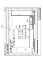
図1は、本発明の実施の形態に係る画像形成装置の概略構成を示す概略構成図である。図1において、100は画像形成装置本体、180は自動原稿給送装置(DF)、101は原稿載置台としてのプラテンガラスである。102はスキャナであり、原稿照明ランプ103や走査ミラー104等から構成されている。スキャナ102は不図示のモータによって所定方向に往復走査する。この往復走査中に原稿からの反射光が走査ミラー104〜106を介してレンズ107を透過し、イメージセンサ部108内のCCDセンサに原稿の画像が結像する。
【0038】
109はレーザやポリゴンスキャナ等で構成された露光制御部である。この露光制御部109は、イメージセンサ部108で電気信号に変換され、かつ、後述する所定の画像処理をされた画像信号に基づいて変調されたレーザ光119を画像形成領域110に臨む感光体ドラム111に照射する。感光体ドラム111の周囲には、1次帯電器112、現像器113、転写帯電器116、前露光ランプ114、クリーニング装置115が配置されている。感光体ドラム111は不図示のモータによって矢印A方向に回転しており、1次帯電器112により所望の電位に帯電された後、露光制御部109からのレーザ光119が照射される。これにより、感光体ドラム111上に静電潜像が形成される。この静電潜像に現像器113からのトナーを付着させると現像されたトナー像になる。
【0039】
一方、第1の給紙カセットデッキ121、第2の給紙カセットデッキ122、上段給紙カセット123あるいは下段給紙カセット124からピックアップローラ125,126,127,128によって給紙された記録紙は、給紙ローラ129,130,131,132によって画像形成領域110に向けて搬送される。給紙カセットデッキ121、122、上段給紙カセット123、下段給紙カセット124は、本実施形態では給紙部とも呼ぶものとする。
【0040】
画像形成部110の近傍まで搬送された記録紙は、レジストローラ133により転写ベルト134に給送される。画像形成領域110で感光体ドラム111に記録紙が接触すると、転写帯電器116によってトナー像が記録紙に転写される。転写後の感光体ドラム111に残ったトナーは、クリーナー装置115によって清掃される。この後、前露光ランプ114によって感光体ドラム111の残留電荷が消去される。
【0041】
転写後の記録紙は、分離帯電器117によって感光体ドラム111から分離され、転写ベルト134によって定着器135に搬送される。記録紙に転写されたトナー像は、定着器135によって加圧されると共に加熱されて定着する。その後、記録紙は排出ローラ136によって画像形成装置本体100の外部に排出される。
【0042】
画像形成装置本体100には、例えば4000枚の記録紙を収納し得るデッキ150が装備されている。デッキ150のリフタ151は、ピックアップローラ152に記録紙が常に当接するように記録紙の量に応じて上昇する。最上部の記録紙は給紙ローラ153によって画像形成装置本体100に送られる。また、100枚の記録紙を収容し得るマルチ手差しトレイ154も装備されている。
【0043】
さらに、図1において、137は排紙フラッパであり、記録紙の進路を搬送経路138と排出経路143の何れか一方に切り替える。記録紙の両面に画像を形成する両面記録(両面複写)の際には、排紙フラッパ137を上方に上げることによって、排紙ローラ136から送り出される記録紙を搬送経路138から、一旦、反転経路139に進入させた後に進行方向を逆転させて下搬送経路140に搬送する。これにより、記録紙は裏返された状態で再給紙経路141に導かれる。
【0044】
第2の給紙カセットデッキ122から給紙ローラ130によって給紙された記録紙も、再給紙経路141に導かれる。142は記録紙を画像形成領域110に再給紙する再給紙ローラである。
【0045】
144は排紙フラッパ137の近傍に配置されており、この排紙フラッパ137により進路を排出経路143側に切り替えられた記録紙を画像形成装置本体100の外部に排出する排出ローラである。画像形成装置本体100から記録紙を反転して排出する際には、排紙フラッパ137を上方に上げ、反転ローラ145によって記録紙の後端が搬送経路138に残った状態の位置まで反転経路139に引き込む。この後、反転ローラ145を逆転させることによって記録紙を裏返して排出ローラ144側に送り出す。
【0046】
190は画像形成装置本体100から排出した記録紙を揃えて閉じる排紙処理装置であり、一枚毎に排出される記録紙を処理トレイ194に積載して揃える。1部分の画像形成の排出が終了したら、記録紙束をステープルして排紙トレイ192、又は、193に束で排出することもできる。排紙トレイ193は不図示のモータで上下に移動制御され、画像形成動作開始前に処理トレイ194に位置するように移動する。191は排出された記録紙の間に挿入する区切り紙を積載する記録紙トレイで、195は排出された記録紙をZ折りにするZ折り機である。また、196は排出された記録紙1部をまとめてセンター折りしステープルを行なうことによって製本を行なう製本機であり、製本された紙束は排出トレイ197に排出される。
【0047】
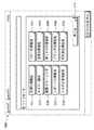
図2は、図1の画像形成装置における制御回路の構成を示すブロック図である。
【0048】
図2において、200は、画像読取り部や画像形成部205などの駆動制御を行なうための画像形成装置の本体制御部であって、CPUと、このCPUの作業領域を提供するRAMと、後述する各動作モードを実行するためのプログラムを含み、画像形成装置全体の制御プログラムを格納したROMとを有する。
【0049】
例えば、この本体制御部200は、CCD201によって読み取られた画像データを画像処理部202において所望の画像データに変換し、画像データセレクタ203において、上記の読み取った画像データをレーザユニット204、画像データ圧縮部207、画像メモリ208、ファンクション制御部209のいずれに流すかを制御し、また、原稿給送装置制御部216に対して、原稿給送の命令を出したり、後処理装置制御部217に対して、どのようなモードを設定するかを指示したりする画像形成装置の装置制御や画像データ制御を行ない、さらに、後述のタブ紙インサートモード、タブ紙作成モード(総称してタブ紙プリントモードと呼ぶものとする)を実行する。
【0050】
201はCCDであり、原稿台、原稿照射部、光学系などからなる原稿読取部218から原稿照射によって得られる原稿画像の反射光を捕らえて光電変換し、画像データを出力する。202の画像処理部では、CCD201から出力される画像データに対して操作部219によって設定される画像処理機能に対応した画像処理を行なう。203は、後述するレーザユニット204、画像データ圧縮部/伸長207、画像メモリ208、ファンクション制御部209と画像データバスが接続されており、画像データの流れを決定する本体制御部200の制御情報により、画像データの流れる方向を選択する画像データセレクタである。
【0051】
204は、画像形成部205で記録紙に現像される画像データに対して、レーザ露光を行なうレーザユニットである。画像形成部205は、上述のように、レーザ露光された画像データを実際に記録紙に現像する。
【0052】
206は、本体制御部200と後述するファンクション制御部209との間で制御情報の通信を行なうためのCPU間通信I/F(インターフェイス)である。207は、画像データセレクタ203から出力された画像データを大容量不揮発性メモリであるハードディスク(HD)に蓄積する際に、HD上での画像データの占有率を節約するために、画像データを圧縮し、またHD上の圧縮された画像データを画像データセレクタヘ転送する際に元の画像データに伸長する画像データ圧縮/伸長部である。208は、画像データセレクタ203から送られてくる画像データを一時的に記憶したり、画像データセレクタ203に対して一時記憶した画像データを転送するための揮発性メモリからなる画像メモリである。
【0053】
209は、本体制御部200と通信を行ない、画像データセレクタ203から送られてきた画像データを後述するスキャン画像変換部213へ流すファンクション制御部である。また、ファンクション制御部209は、後述するネットワーク通信I/F215から送られてきたプリント画像データを変換するプリント画像変換部214が送ってくる画像データを画像データセレクタ203へ流すための画像データ制御情報や、本体の操作部219からの画像形成装置制御情報をCPU間の通信を行なうCPU間通信I/F210を介して、本体制御部200と通信する。
【0054】
CPU間通信I/F210は、後述するHD制御部211と本体制御部200との間で、HD212に記憶される画像データの制御情報の通信を行なう。HD制御部211は、画像データ圧縮/伸長部207から流されてくる画像データをHD212に書き込んだり、HD212に記憶されている画像データを読み出して、画像データ圧縮/伸長部207に流すような制御をCPU間通信I/F210を通して送られてくる本体制御部200からの制御情報に基づいて行なったりする。
【0055】
HD212は、HD制御部211の制御に基づいて、画像データ圧縮/伸長部207から送られてくる画像データ、または画像データ圧縮/伸長部207に送る画像データの書き込み、読み出しが行なわれる不揮発性メモリである。
【0056】
213はスキャン画像変換部であり、本体制御部200の制御に基づいて画像データセレクタ203から流される画像データを、後述するネットワーク通信I/F215においてネットワーク接続されるホストコンピュータ上で動作するアプリケーションソフトにおいて読み込みが可能となるように変換する。214は、後述するネットワーク通信I/F215においてネットワーク接続されるホストコンピュータ上で動作するアプリケーションソフトから転送されてくるPDLで記述された画像データを画像形成装置の画像形成部205において印字出力できるような画像データに変換するプリント画像変換部である。
【0057】
215は、画像形成装置とネットワーク接続するための通信I/Fであり、特定の通信規約(プロトコル)に基づいて、ネットワーク上の機器(コンピュータなど)と画像データや制御情報の通信を行なう。
【0058】
216は、図3において詳述する複数の原稿を原稿台まで給送する原稿給送装置101を制御する原稿給送装置制御部であり、本体制御部200からの制御情報に基づいて原稿を給送する。217は、出力記録紙の後処理を行なう後処理装置制御部であり、本体制御部200からの制御情報に基づいて、画像形成の終了した記録紙(以下、出力紙と記す。)の後処理を行なう。原稿読取部218は装置制御部200からの制御情報に基づいて、原稿照射を行ない、光学系を駆動することにより、CCD201に原稿画像の反射光を投射する。
【0059】
219は、本発明の実施の形態である画像形成装置の操作部である。操作部219から入力されたキーの情報をファンクション制御部209に通知し、ファンクション制御部209で、キーのコマンド解析を行ない、本体制御部200に対して、装置の動作制御情報をCPU間I/F206を通して通知する。
【0060】
この図2の回路構成における基本的な動作を説明するために、50%の縮小コピーをする場合を例に挙げて説明する。
【0061】
まず操作部219において、縮小50%の表示されているキーが押下されると、ファンクション制御部209に通知される。ファンクション制御部209において、縮小50%のキーが押されたことをコマンド解析し、ファンクション制御部209はその情報を記憶する。次に操作部219において、コピースタートボタンが押下されると、ファンクション制御部209に通知される。ファンクション制御部209では、コピースタートボタンが押下されたことをコマンド解析し、CPU間通信I/F206を通して、本体制御部200にコピーモード、縮小50%、置数(コピーする数:この場合は1)などのコピー情報とともにコピースタートであることを通知する。
【0062】
本体制御部200では、このファンクション制御部209からの通知を受け、原稿給送装置制御部216、後処理装置制御部217、及びCPU間通信I/F210を通してHD制御部211の状態を監視し、コピースタート可能であることを判断した後に、画像処理部202に縮小50%の設定を行なう。また、コピーモードであることから、画像データセレクタ203によって画像データ圧縮/伸長部207、画像メモリ208、及びレーザーユニット204に画像データが流れるように画像経路を設定する。コピースタートであることから、原稿給送装置101の状態を原稿給送装置制御部216を通して確認し、原稿が存在する場合には、原稿を給送するように原稿給送装置制御部216に指示を出し、原稿読取部218に対して原稿給送装置101から給送された原稿を読み取れる位置に移動する指示を出す。また、同時に後処理装置の状態を後処理装置制御部217を通して確認し、画像形成部205から印字出力される記録紙の排出を受けられるように指示を出す。
【0063】
さらに、原稿を読み取った画像が画像データセレクタ203と画像データ圧縮/伸長部207とを通してHD212に書き込まれる。このため、HD212への画像書込みを行う場合、また、原稿が複数枚である場合や置数が複数である場合には、HD212からの読出しの設定を行なうようにCPU間通信I/F210を通して、HD制御部211に指示を出す。
【0064】
また、コピー動作を行なえるように、CCD201、レーザユニット204、画像形成部205に初期設定を行ない、原稿給送装置101が原稿を原稿読取り位置まで給送したことを原稿給送装置制御部216から、後処理装置が画像形成部205からの印字出力記録紙の排出を受けられることを後処理装置制御部217から、原稿台上の原稿を読取れる位置に原稿読取部218が達したこと、画像形成部205における印字出力記録紙が印字可能になったことを確認し、画像読取り、画像印字出力を開始するために原稿画像の反射光をCCD201が光電変換している画像データを受け取るように、画像処理部202、画像データセレクタ203、画像メモ208、画像データ圧縮/伸長部207、HD制御部211に画像データ取り込み開始を指示する。
【0065】
ここで、置数が1であるので、画像メモリ208に書き込まれた画像データが印字出力可能であるところまで書き込まれる時間を本体制御部200で計測し、その時間に達したら、画像データセレクタ203、レーザユニット204、画像形成部205に対して、印字出力の開始を指示する。
【0066】
図3は、図2における操作部219を詳細に示す図である。図3において301は、コピーの置数や画像移動量などを入力するときに使用するテンキーである。302は、スタートキーで、コピージョブをスタートさせるときなどに使用する。303はストップキーで、スタートしたジョブを途中で停止させたいときなどに押下して、ジョブをストップできる。
【0067】
304は、LCD表示・入力部で、一般にコピージョブのモードを設定することや複写機の動作状態を表示するために使用される。LCD表示・入力部304はタッチパネルディスプレイにより構成される。305は、複写機に関する標準モードに反映させる動作や表示の設定などを行なうユーザモードの各項目の設定を行なうためのユーザモードキーである。306は節電モードキーであり、ユーザがコピーなどのジョブ終了後、スタンバイ状態で複写機本体を節電する節電モードへ移行するためのキーである。
【0068】
図4から図8までは、ユーザモードにおけるタブ紙給紙部の設定のためのLCD表示・入力部304に表示される画面を示す図である。LCD表示・入力部304に表示される画面はファンクション制御部209により制御される。図4は、図3のユーザモードキー305を押下したときにLCD304に表示される画面を示す図である。このユーザモードウインドウ500には、設定されるべき項目が列挙されている。コピー機能、プリンタ機能など複写機のいずれの機能を利用するときにも機能全体に及ぶような共通のユーザ仕様を設定する共通仕様設定キー501、コピー機能に特化したユーザ仕様を設定するコピー仕様設定キー502、節電時間や複写機の電源オフ時間の設定を行なうタイマー設定キー503、読み取った原稿画像を送信するためのユーザ仕様設定を行なう送信仕様設定キー504、複写機の複写プロセス条件や読み取り濃度などの調整やADFのローラクリーニングなどを行なう調整/クリーニングキー505、読み取った原稿やプリント画像変換部214から送られてくる画像データを格納する機能であるボックス機能のユーザ仕様設定を行なうボックス仕様設定キー506、コピージョブ、プリントジョブ、スキャンジョブなどのレポートの仕様設定を行なうレポート仕様設定キー507、プリント画像変換部214の仕様設定を行なうプリンタ仕様設定キー508、複写機本体の管理者パスワードなどのシステム設定を行なうシステム管理設定キー509、読み取り画像の送信機能で使用される宛先登録などを行なう宛先表仕様設定キー510などのユーザモードにおける設定項目がある。
【0069】
また、511はユーザモードウインドウ500を閉じるためのキーである。このキー511を押下すると、後述する図9の標準画面に移行する。また、ユーザモードキー305を押下しても図9の標準画面に移行させることもできる。
【0070】
図5は、図4の共通仕様設定キー501を押下したときに表示される共通仕様設定ウインドウを示す図である。共通仕様設定ウインドウ512には共通仕様設定項目の一覧が表示される。上方スクロールキー517、下方スクロールキー518により、他の項目へとウインドウ512を移動表示する。
【0071】
上方スクロールキー517と下方スクロールキー518との間に2/3と表示されているものは、全体が3ページある中でスクロールしたページが2ページ目であることを示すものである。この中で記録紙タイプ登録キー513は、121〜124、150の各給紙カセットにどのような種類(普通紙、色紙など)の記録紙が挿入されているかをLCD表示・入力部304上で明示的にするためにその記録紙タイプを登録するためのキーである。
【0072】
節電モード変更キー514は、節電モードキー306が押下されたときの節電モード時に、電力の消費量などをどの程度抑えるかの設定を行なうためのものである。スリープ時の消費電力キー515は、複写機本体のスリープ状態の程度を設定するキーであり、すなわち本体制御部200、原稿給送装置制御部216、後処理装置制御部217、HD制御部211などの各制御部とそれぞれのモータやユニットなどの各負荷を電源OFFにするレベルを設定するものである。このとき、操作部219と接続されているファンクション制御部209は、消費電力が少ないことから電源OFFの対象外となっており、スリープからの復帰を受け持っている。
【0073】
516は幅方向が同じ長さであるLTRR原稿とSTMT原稿のどちらを原稿としてみなすかを決定するLTRR・STMT原稿の区別キーである。また、519はこの共通仕様設定ウインドウ512を閉じるためのキーである。このキー519を押下するとユーザモードウインドウ500に戻る。
【0074】
図6は、記録紙タイプ登録キー513を押下したときに表示される記録紙タイプの登録設定をするためのサブウインドウ520を示す図である。521〜525は、それぞれ図1における各給紙部121〜124、150に対応した給紙部キーである。この中で記録紙タイプを登録したい給紙部キー521〜525を押下し、図7の記録紙タイプ設定サブウインドウ530を開く。
【0075】
531は、給紙部に収容された記録紙が64g/mmなどの普通紙であることを登録する普通紙登録キーである。532は、給紙部に収容された記録紙が再生紙であることを登録する再生紙登録キーである。533は、給紙部に収容された記録紙が色紙であることを登録する色紙登録キーである。
【0076】
534は、給紙部に収容された記録紙がタブ紙であることを登録するタブ紙登録キーである。このタブ紙登録キー534を押下すると図8のようにタブ紙分割数入力サブウインドウ540が表示される。ここで分割数とは、市販のタブ紙が、通常、異なる位置に耳部(タブ部)を持つタブ紙を順番に1枚ずつ重ねた構成を1セットとし、複数セットを1束とし市販されており、このタブ紙1セット当たりの枚数を指す。マイナスキー541とプラスキー542により、分割数表示窓543に表示される分割数を設定する。タブ紙は一般に5枚1セットになった5タブ紙が一般的であるが、本実施の形態では1枚1セットの1タブ紙から20枚1セットになった20タブ紙までを扱えるように設定できる。
【0077】
このように1セットあたりの分割数を予め登録しておくことにより、後述するようにタブ紙をコピーする際に複写機本体に挿入されているタブ紙の給紙部とその分割数を入力する手順を減らすだけでなく、ネットワーク通信I/F部215を通してネットワーク上の機器から、どの給紙部に何分割のタブ紙が挿入されているかの問い合わせがあった場合に正確に応えられる。
【0078】
マイナスキー541とプラスキー542により分割数を設定後、タブ紙分割数入力サブウインドウ540を閉じるためのキー544を押下すると、記録紙タイプ設定サブウインドウ530に戻る。さらに、記録紙タイプ設定サブウインドウ530において、記録紙タイプの入力が終了してOKキー536を押下すると、設定を登録して共通仕様設定ウインドウ512に戻る。
【0079】
また記録紙タイプ設定サブウインドウ530において、設定した内容を登録したくないときは、キャンセルキー535を押下することにより、設定を登録せずに共通仕様設定ウインドウ512に戻ることもできる。
【0080】
このようにして複写機に挿入されているタブ紙の給紙部とタブ紙の分割数の登録を予め行なう。
【0081】
ここで、タブ紙給紙部、タブ紙分割数が登録されていないときには、図11のようにコピーを行なうときのさまざまなモード設定を行なう応用モード画面において、タブ紙関連のモード設定キーは表示されない。つまり、図11の画面においてタブ紙インサートモードキー344、タブ紙作成モードキー345が表示されない。
【0082】
尚、図11の画面においてタブ紙インサートモードキー344、タブ紙作成モードキー345を表示しても網掛け表示など他のキーとは異なる表示にし、これらのキーが押されても選択出来ないようにしてもよい。
【0083】
一方、タブ紙給紙部、タブ紙分割数が予め登録されているときには、図11のようにタブ紙インサートモードキー344、タブ紙作成モードキー345が表示され、タブ紙関連の設定が可能となる。
【0084】
図9から図11までに、図3のLCD表示・入力部304を詳細に例示する。ユーザモードウインドウ500(図4参照)において、キー511が押下されたときに戻る表示画面が図9の標準画面310である。この標準画面310は応用モードのアイコンであり、押下すると各種モード設定を行なうサブウインドウが開く。
【0085】
315は、原稿の複写を行なうコピー機能、スキャン画像変換部213やネットワーク通信I/F215などを介してネットワーク上の機器へ原稿画像データを送信する送信機能、原稿を画像データとしてHD212に格納し、後にプリントしたり、コピーしたり、スキャン画像変換部213、ネットワーク通信I/F215を介してネットワーク上の機器に送信したりする、原稿画像データを蓄積するボックス機能、ネットワーク上の機器からの画像データをネットワーク通信I/F215からプリント画像変換部214を介して画像形成を行なうプリント機能をはじめとする拡張機能などの各ジョブの機能を選択できるキー群である。
【0086】
312は、給紙部選択アイコンであり、押下すると図10に示すような給紙部を選択するためのサブウインドウが開き、給紙部の表示・選択が行なえる。
【0087】
314は画像モードを決定するキー群で、自動濃度補正、文字モード、文字写真モード、写真モードなどの各種の画像モードを選択し、文字モード、文字写真モード、写真モードが選択されたときには、濃度キーにより、濃度を変化させることができる。
【0088】
313は、原稿の倍率を変化させるためのキー群で、100%等倍、縮小、拡大、1%刻みのズームキーや原稿全体をコピーするときに使用する「少し小さめ」キーなどの各種のキーが含まれる。いずれの場合にも、原稿の倍率を変化させるもので、倍率設定後は設定された倍率が表示される。316はソータキーであり、記録紙が出力された後、フィニッシングを設定する。例えば、複数枚の原稿をまとめた1部の出力を複数部出力したいときのソートモード、各原稿1ページを設定した置数分出力するグループソート、ソートモードで出力した記録紙を1群ごとにまとめてステープルするステープルモードなどがある。
【0089】
317は両面キーであり、原稿の片面を読み込むか又は両面を読み込むか、記録紙の片面に出力するか又両面に出力するかのような各種のモードを設定する。各種のモードには、原稿の片面を読み込んで記録紙の両面に出力する片両モード、原稿の両面を読み込んで記録紙の両面に出力する両両モード、原稿の両面を読み込んで記録紙の片面に出力する両片モード、原稿の片面を2分割して読み込んで記録紙の両面に出力するページ連写両面モードなどが含まれる。また318は、割り込みキーであり、大量部数のコピージョブなどを行なっているときに、途中で中断して別のコピーを取りたいときなどに使用される。
【0090】
図10は、図9の記録紙選択キー312を押下したときに表示されるサブウインドウであり、画像形成装置本体100の第1の給紙カセットデッキ121、第2の給紙カセットデッキ122、上段カセット123あるいは下段カセット124、デッキ150、及びマルチ手差しトレイ154の各給紙部のうち、選択する給紙部を設定する。
【0091】
321はマルチ手差しトレイ154に対応するキーである。322はA4記録紙が収容されている第1の給紙カセットデッキ121に対応しているキーである。323はA3記録紙が収容されている第2の給紙カセットデッキ122に対応して対応しているキーである。
【0092】
324は上段カセット123に対応するキーであり、図10においてタブ紙給紙部として設定されたタブ紙給紙部の表示がなされている。A4サイズのタブ紙が収容されていることを示しており、これにより、ユーザはタブ紙をどこにセットすればよいか又はどこに設定されているかを認識できる。
【0093】
325は下段カセット124に対応するキーであり、A4記録紙に設定されているが、記録紙が収容されていないことを示している。326はデッキ150に対応するキーであり、A3記録紙が収容されていることを示している。327は自動給紙選択キーで、自動給紙選択されているときには、原稿サイズと設定されたコピーモードから最適な記録紙検出を自動的に行ない、見つからなかった場合には、第二候補の記録紙サイズを選択する。
【0094】
図11は、図9における応用モードキー311を押下したときのサブウインドウであり、それぞれ各コピーモードを設定する機能のアイコンが表示されている。340はページ連写キーであり、原稿を見開きとしてみなし、2分割して二つの原稿として読み取るモードである。341は表紙/合紙キーであり、出力紙に表紙や裏表紙、仕切りのための合紙を給紙部選択して1部のコピーを出力させるモードである。342は製本モードキーであり、原稿をコピーした出力紙の中央で中折りしたときに見開きの本のように出力するモードである。343はネガポジ反転キーであり、原稿画像の白部分を黒に、黒部分を白にコピーするモードである。
【0095】
345はタブ紙作成キーであり、このキーが押されることにより図10に示す上カセット324のようにタブ紙給紙部がある場合、タブ紙を給紙し、原稿に印字されているタブ部分に対応する画像をタブ位置に移動させてタブ紙のタブ部分に印字するタブ紙作成モードが設定される。
【0096】
344はタブ紙インサートキーであり、このキーが押されることにより図10に示す上カセット324のようにタブ紙給紙部がある場合、タブ紙を合紙のように仕切り記録紙として使用し、タブ部分に対応するコピー原稿でタブに印字するために画像移動などを行なうタブ紙インサートモードが設定される。
【0097】
346はモードメモリキーであり、このキー操作によって応用モードやキー316(図9参照)で設定されたソートモード、キー315で設定された変倍モード、キー314で設定された画像モードなど設定された各種モードが記憶される。347はコールキーであり、このキーを押下することによって前回のコピー時の設定を呼び戻すことができる。348はイメージ合成キーであり、背景の画像を登録したり、予め登録されている背景の画像を原稿に重ね合わせて出力するときに操作する。
【0098】
349は、原稿混載キーであり、自動原稿給送装置180に複数の原稿が載置され、A4サイズの原稿とA3サイズの原稿とが混在しているときに操作するキーである。350は、OHP中差しキーであり、マルチ手差しトレイ154などにOHP用紙が設定されているときに、マルチ手差しトレイ154からOHPを給紙し、印字し、同じ画像を他の給紙部から給紙された普通の記録紙に印字したり、また印字せずに出力させたりするOHPの中差し記録紙をOHPの間に入れるときに操作するキーである。
【0099】
351は移動キーであり、記録紙に対して原稿画像をどのように移動させるかを設定するときに操作するキーである。352はとじ代キーであり、出力紙にとじ代を作成するために、画像を移動させるときに操作するキーである。353は枠消しキーであり、原稿画像の外枠を消去したり、印字時に記録紙の外枠の画像を消去したりするときに操作するキーである。354は縮小レイアウトキーであり、複数の原稿を1枚の記録紙にレイアウトして印字するときに操作するキーである。355は拡大レイアウトキーであり、縮小レイアウトキー354などで作成された1枚あたりの複数の画像を分割して、印字するときに操作するキーである。356は、応用モードのサブウインドウを閉じ、標準画面310に戻るためのキーである。
【0100】
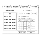
図12は、図11におけるタブ紙作成キー345、タブ紙インサートキー344が押下されたときに開くサブウインドウであり、タブ紙給紙部からタブ紙が給紙され、印字を行なうときの画像移動量を設定するサブウインドウである。この移動量は、図28に示す様に、原稿の画像のうち記録紙のタブ部に印字する画像を記録紙のタブ部に印字できるように、その画像を移動させる移動量である。A4サイズのタブ紙の場合、通常は12mmほど移動させればよいが、本実施の形態ではタブに印字する文字の大きさや原稿上の位置によりその移動量が変化するため、0mmから25mmの範囲で移動量を設定できる。
【0101】
330は移動量を少なくするときに操作するマイナスキーであり、331は移動量を増やすときに操作するプラスキーである。332は現在設定しようとしている移動量を表示している部分である。333は、移動量の設定をキャンセルし、タブ分割数を設定するための入力画面であるサブウインドウ(図11参照)に戻るときに操作する取り消しキーである。334は、332に表示されている移動量を設定するときに操作するOKキーである。
【0102】
図12のOKキー334が押されると図13に示すタブ紙インサートモード画面が表示される。図13は、タブ紙の挿入を設定するタブインサートモードの表示画面を示す図である。370は、タブ紙を挿入するページを表示する挿入ページウインドウで、1枚目のタブ紙を選択するときには、「1枚目」と表示された部分を押下し、テンキー301により、タブ紙が挿入されるべきページ数を入力する。図示した例では、1枚目が「2ページの前」に設定されているので、1枚目のタブ紙が1ページと2ページとの間に挿入される。同様に2枚目のタブ紙が2ページと3ページとの間に挿入され、3枚目のタブ紙が3ページと4ページとの間に挿入され、4枚目のタブ紙が4ページと5ページとの間に挿入され、5枚目のタブ紙が7ページと8ページとの間に挿入されるように設定されている。
【0103】
371は取消キーであり、この取消キー371の操作によってタブ紙の挿入設定をキャンセルできる。タブ紙の挿入設定をキャンセルすると、タブ紙に印刷する画像の移動量を設定するサブウインドウ(図12)に戻る。372は、タブ紙を挿入するページが7箇所以上である場合に、挿入ページウインドウ370をスクロールアップするキーである。373は、タブ紙を挿入するページが7箇所以上である場合に、挿入ページウインドウ370をスクロールダウンさせるキーである。374は、挿入ページウインドウで設定されたタブ紙の挿入をコピージョブで実行するためのOKキーであり、このOKキー374が押されることによってタブ紙インサートモードの設定が完了する。
【0104】
以上のように図11から図13までを参照して説明した方法に従ってタブ分割数、タブ紙画像移動量、及びタブ紙挿入ページが設定される。
【0105】
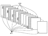
図14は、タブ紙インサートモードにおける原稿の配列例を示す図である。
【0106】
図15は、タブ紙インサートモードにおける出力紙の配列例を示す図である。
【0107】
この例では、原稿サイズと記録紙サイズは一致しているが、タブ画像原稿400とその画像を形成するタブ紙411とでは、タブ紙411からタブ部が突出している点のみが異なる。タブ画像原稿400は、原稿401の間に挟まれている。タブ画像原稿400の画像は設定された移動量だけ移動されて、タブ紙410に印字される。
【0108】
図16は、タブ紙作成モードにおける原稿の配列例を示す図である。
【0109】
図17は、タブ紙作成モードで画像形成された出力紙の配列例を示す図である。図16のタブ画像原稿に印字されていた画像が、設定された移動量だけ移動して、タブ紙のタブ部に印字される。
【0110】
図18は、タブ紙インサートモードにおける画面の遷移を示す図である。標準画面310(図9参照)から応用モードキー311が押下されたときに応用モード画面(図11参照)と同じ応用モード画面600が表示される。応用モード画面600でタブ紙インサートキー601が押下されると、タブ紙への画像移動量を設定するサブウインドウ(図12参照)と同じ画像移動量を設定するサブウインドウ(画像移動量サブウインドウ)610が表示される。この画像移動量サブウインドウ610では、タブ紙の1セットあたりの分割数が分割数表示領域613に表示される。本実施の形態では、図8のように1セットあたり5分割のタブ紙を設定しているため、タブ紙分割数は5と表示されている。取消キー611が押下されると、応用モード画面600に戻る。
【0111】
画像移動量サブウインドウ610において、OKキー612が押下されると、インサートページを設定するサブウインドウ(図13参照)と同じ画面のインサートページ設定画面620が表示される。取消キー621が押下されると、画像移動量サブウインドウ610に戻る。
【0112】
インサートページ設定画面620では、OKキー622が押下されると、応用モード画面600に戻り、タブ紙インサートモードにおける一連の設定が終了する。また、このとき、標準画面310に戻ってもよい。インサートページ設定画面620において、取消キー621が押下されると、タブ紙の画像移動量サブウインドウ610に戻る。
【0113】
図19は、タブ紙作成モードにおける画面の遷移を示す図である。標準画面310において応用モードキー311が押下されると、応用モード画面700が表示される。応用モード画面700でタブ紙作成キー701が押下されると、画像移動量サブウインドウ710が表示される。この画像移動量サブウインドウ710には、タブ紙の1セットあたりの分割数が分割数表示領域713に表示される。本実施の形態では、図8のように1セットあたり5分割のタブ紙を設定しているため、タブ紙分割数は5と表示されている。取消キー711が押下されると、応用モード画面700に戻る。画像移動量サブウインドウ710では、OKキー712が押下されると、応用モード画面700に戻り、タブ紙作成モードの設定が終了する。なお、このとき、図9の標準画面310に戻るようにしてもよい。以上で述べた設定情報、例えば、設定されたタブ紙の給紙部とタブ紙の分割数等の設定情報は、1度電源OFFした後も記憶している。
【0114】
以上のように、原稿の間にタブ画像原稿が挿入されているときに本文とタブ紙のタブ部への同時コピーを行なうタブ紙インサートモードやタブ紙用の原稿からタブ紙のタブ部へのコピーを行うための設定を行う。
【0115】
次にこのタブ紙インサートモードやタブ紙作成モードを表示するためのタブ紙給紙部やタブ紙分割数の設定を保存する方法について、図20、図21を用いて説明する。
【0116】
図20は、図2のファンクション制御部209の回路構成の概略ブロック図である。1801は、ROMであり、ファンクション制御部209によって実行される制御プログラムが内蔵記憶されており、画像形成装置本体の電源が投入されたとき、RAM1802に展開され、CPU1805において、実行される。1803は、バックアップRAMであり、ROM1801に格納されているプログラムの実行により変更され、次回の電源投入時までも保存しておく必要がある設定データが保存される。例えば、本実施の形態において設定されるタブ紙給紙部やタブ紙分割数などが保存され、次回電源投入時にその設定を読み出すことが可能となる。
【0117】
本実施の形態においては、バックアップRAMとしたが、EEPROM、HDDでも不揮発性の読み書き可能なメモリ媒体であれば良い。1804は、操作部駆動回路であり、図2の操作部219を駆動する回路である。図3に示す操作部の301〜303、305の各キーの入力を受けて該入力の内容をCPU1805に渡したり、LCD表示・入力部304への表示データをCPU1805からの指示により、表示させる。
【0118】
1806は、ネットワークI/F駆動回路であり、ネットワーク通信I/F215を駆動するための回路である。ネットワークを介して接続されるホストコンピュータからのデータを受け取り、そのデータの種類により、プリント画像変換部214がプリント画像データを受け取れるように設定したり、ファンクション制御部209が所有している画像形成装置本体制御部200の各種データを送出したり、原稿読み取り部218によりスキャンされた原稿画像を画像メモリ208からスキャン画像変更部213からの画像データを送出するように設定変更するための回路である。
【0119】
1807は、スキャン画像変換部駆動回路であり、スキャン画像変換部213を駆動するための回路である。これは、原稿読み取り部218、CCD201により、スキャンされ、画像処理部202を介して画像メモリ208に一時的に保存されているか、HD212からの蓄積圧縮画像ビットマップデータを画像データ圧縮/伸長部207によりビットマップデータにもどされた原稿画像のビットマップデータを所定のフォーマット(例えばJPEGFなど)に変換するための回路である。1808は、プリント画像変換部駆動回路であり、ホストコンピュータからの画像データをネットワークI/F回路で受けたあと、CPU1805の指示により所定のビットマップ画像データに変換する回路である。
【0120】
以上のような回路構成において、タブ紙給紙部やタブ紙分割数がどのように設定保存され、タブ紙インサートモードやタブ紙作成モードのようなタブ紙プリントモードを操作部219上のLCD表示・入力部304に設定/表示可能とするかを図21の(a)及び図21(b)のフローチャートで説明する。
【0121】
まず、図21の(a)のS1901において、画像形成装置本体の電源が投入され、本体制御部200、原稿給送装置制御部216、後処理装置制御部217、HD制御部211、ファンクション制御部209、などに含まれるCPUが稼働し、本実施の形態におけるファンクション制御部209においては、ROM1801のプログラムデータがRAM1802に展開され、CPU1805において実行される。S1902においてバックアップRAM1803に保存されているバックアップデータを読み出し、画像形成装置本体制御部200に含まれる各種設定項目をバックアップデータにしたがって設定する。特にファンクション制御部209が制御する操作部219に対しては操作部駆動回路1804を介してバックアップデータに従った各種モード設定を行なう。
【0122】
ステップS1903において、その各種設定の一つである、タブ紙給紙部、タブ紙分割数に関する、タブ紙給紙部設定用のバックアップデータがあるか否かを判別し、タブ紙給紙部設定用のバックアップデータがある場合には、ステップS1904で操作部219に対して、応用モードキー311が押された際に図11のようにタブ紙プリントモード(つまり、タブ紙インサートモードやタブ紙作成モードなどのタブ紙プリントモード)に関するキーを表示するように操作部駆動回路1804を介して設定を行なう。
【0123】
一方、タブ紙給紙部設定用のバックアップデータがない場合には、ステップS1905で操作部219に対して、応用モードキー311が押された際に図11のタブ紙プリントモード(つまり、タブ紙インサートモードやタブ紙作成モードなどのタブ紙プリントモード)に関するキー344及び345を表示しないように操作部駆動回路1804を介して設定を行なう。これでステップS1901の電源投入後の初期設定が終り、スタンバイの状態になる。
【0124】
図21の(b)のステップS1906で操作部219からユーザモードキー305が押下されると、図4の画面を表示し、共通仕様設定キー501を押下し図5の画面を表示させる。用紙のタイプを登録する場合は、ステップS1907において用紙タイプの登録キー513が押下されると図6の画面が表示される。ステップS1908でタブ紙が収納される給紙部を設定する。収納する用紙タイプはタブ紙なので、図7の画面でタブ紙キー534を押下する。ステップS1909において、操作部219からタブ紙分割数が入力されたときは当該タブ紙分割数を、または入力されない場合は所定のタブ紙分割数を設定する。そして、ステップS1910において、設定、即ち選択されたタブ紙給紙部とそのタブ紙分割数をバックアップデータとして、バックアップRAM1803に記憶する。
【0125】
以上が終了した時点でステップS1911において、タブ紙インサートモードやタブ紙作成モードなどのタブ紙プリントモードに関するキーを操作部219に対して表示可能とするように操作部駆動回路1804を介して設定を変更する。ステップS1907において用紙のタイプを登録しないのであればステップS1912で他の設定が行なわれる。
【0126】
このような設定情報の設定作業は、実際の複写に関する操作を行なう前に予め行なっておくのが通常であり、前記実施の形態では予めユーザモードにてタブ紙の給紙部とタブ紙の分割数等の設定をおこない、これらが指定されていることに応じてタブ紙プリントモードを選択可能とした。そして一旦設定した上は、その設定情報をそのまま使用して日常の画像形成装置の動作を実施することが可能で、すなわち、設定された情報は装置本体の電源をOFFしても、設定情報を記憶部に記憶・保持することで、再び電源を立ち上げたときには、電源OFF前の設定情報をそのまま使用することができる。このようにすることで、一々、設定情報の入力作業を行なわなければらないといった不具合を回避することができることから、設定のわずらわしさを解消し、操作性の良い画像形成装置を提供することができる。
【0127】
他の実施の形態として、事前の設定の有無に係わらず、応用モードキー311が押された際に図11のタブ紙プリントモードに関するキー344及び345を表示させる場合を述べる。つまり、まずタブ紙プリントモードの選択は可能とし、そのタブ紙プリントモード設定操作の一連の流れの中で1度だけ、タブ紙給紙部及び分割数を設定させ、その設定を上記と同様、記憶しておき、次回(二度目の設定操作以降)のタブ紙プリントモードの設定では、この記憶した値を読み出すことで、予め給紙部とタブ紙の分割数等の設定がされているときと同様にタブ紙給紙部及び分割数の設定を省略させるものである。
【0128】
このような場合にタブ紙インサートモードやタブ紙作成モードのようなタブ紙プリントモードを操作部219上のLCD表示・入力部304に設定/表示可能とするための手順を図29のフローチャートでを参照して説明する。
【0129】
予め操作部219に対して、応用モードキー311が押された際に図11のようにタブ紙プリントモードのキーが選択可能となるように操作部駆動回路1804を介して設定が行なわれる。ステップS2901において、応用モードキー311が押下され、ステップS2902でタブ紙インサートモードキー344やタブ紙作成モードキー345が押下されると、ステップS2903においてバックアップRAM1803に保存されているバックアップデータが読みだされ、ステップS2904において、バックアップデータの一つである、タブ紙給紙部とタブ紙分割数に関する設定のバックアップデータがあるか否かを判別し、タブ紙給紙部設定がない場合には、ステップS2905にてタブ紙給紙部を設定するために図6と同様の画面が表示され、給紙部を選択する。一方、収納する用紙はタブ紙なので図7の用紙タイプの登録画面は省略可能である。次にステップS2906において、操作部219から所定のタブ紙分割数を設定する。そして、ステップS2907において、選択されたタブ紙給紙部とそのタブ紙分割数をバックアップデータとして、バックアップRAM1803に記憶する。ステップS2908において図18の画面610の分割数表示領域613に示すようにタブ紙プリントモードの設定画面中にタブ紙分割数を表示可能なように操作部29を設定し、ステップS2909でタブ紙への画像移動量やインサートページを設定するサブウインドウ(図12や図13参照)などを表示し、タブ紙プリントモードの設定を行なう。
【0130】
ステップS2904おいて、タブ紙給紙部とタブ紙分割数に関する設定のバックアップデータがあると判断した場合(既にステップS2905〜S2907の設定が行なわれている場合)、つまりタブ紙プリントキーの押下が二回目以降の時は、タブ紙給紙部の設定ステップS2905とタブ紙分割数の設定ステップS2906は行なわず、ステップS2908において図18の画面610の分割数表示領域613に示すようにタブ紙プリントモードの設定画面中にタブ紙分割数を表示可能なように操作部駆動回路1804を介して設定が行なわれる。
【0131】
よって、この様に制御することで次回タブ紙プリントモードの設定を行なう際には、既にタブ紙給紙部と、そのタブ紙分割数がバックアップデータとして、バックアップRAM1803に記憶されているので、タブ紙給紙部の設定とそのタブ紙分割数の設定を省略できる。つまり、図6、図7及び図8の画面は表示せずに、例えば、タブ紙インサートモードであれば図18と同様な画面遷移となる。
【0132】
尚、どの実施の形態についてもいえることであるが、複数の給紙部にタブ紙が収納されている場合は、どの給紙部から給紙するかの指定が必要である。その場合でもタブ紙の分割数はその給紙部ごとに設定されているのでタブ紙プリントモードの設定の際にタブ紙の分割数が改めて設定される必要は無い。よって、少なくともタブ紙の分割数、つまりタブ紙1セット当たりの枚数の設定は要求されないことになる。
【0133】
次にホストコンピュータで本発明の画像形成装置からタブ紙プリントモードでプリントアウトするとき、そのタブ紙プリントモードの設定方法やタブ紙に関する情報の取得方法について述べる。
【0134】
まず、ホストコンピュータがPCである場合、画像形成装置専用のソフトウェアが用意されていることが一般的である。このソフトウェアを一般にプリンタドライバと称している。本実施の形態の画像形成装置においても、専用のプリンタドライバが用意され、画像形成装置の機能であるステープルや両面などの各種機能の設定を行なうことが可能である。ここでは、ホストコンピュータの本画像形成装置設定用の専用のソフトウェア(プリンタドライバ)により、本画像形成装置へタブ紙の給紙部情報やタブ紙分割数などの情報を要求する方法について詳述する。
【0135】
図22に画像形成装置100とホストコンピュータ(PC1、PC2、PC3、PC4)のネットワーク接続例を示す。画像形成装置と各ホストコンピュータは、ネットワークにより各々接続可能であり、各ホストコンピュータはI/Fネットワーク通信I/F215を介して、ネットワークI/F駆動回路1806により、画像形成装置本体100の内部データを取得可能である。この場合の内部データとは、RAM1802上にある動作情報データやバックアップRAM1803に含まれる各種設定であり、各ホストコンピュータへ送出可能である。各ホストコンピュータは、それぞれ画像形成装置でプリントアウトを行なう場合、前述のプリンタドライバにより、画像形成装置で可能な印刷モードを設定する。
【0136】
本発明の画像形成装置はタブ紙の給紙をサポートしているので、各ホストコンピュータは、画像形成装置内のタブ紙給紙部設定のデータやタブ紙分割数のデータなどに応じてプリンタドライバ上でタブ紙プリントモードの設定項目の表示/非表示、およびこれら項目の設定を行なう。図23の(a)及び(b)に画像形成装置とプリンタドライバのタブ紙給紙部情報の取得方法についてのフローチャートを示す。(a)は、画像形成装置本体100を実行動作するためのファンクション制御部209に含まれるデータをネットワーク通信I/F215を介してネットワーク上接続可能なホストコンピュータに公開する不図示のデータ公開部の情報提供方法を示すフローチャートである。
【0137】
本フローチャートにおいては、タブ紙に関するものの公開方法についてのみ、詳述している。ステップS2100において、画像形成装置の電源がONまたは装置の初期化がされ、ファンクション制御部209の各プログラムが起動され、データ公開部のプログラムもRAM1802上に展開され、動作を開始する。ステップS2101においては、ネットワーク通信I/F部215を経由して、ホストコンピュータが必要とするデータ情報を公開するための初期設定を行なう。その後、ステップS2102において、給紙部情報取得要求待ちとなり、各ホストコンピュータからの給紙部情報要求を待つ。
【0138】
各ホストコンピュータのうち1台のホストコンピュータから給紙部情報取得要求があった場合、ステップS2103において、画像形成装置本体の給紙部情報をネットワークI/F駆動回路1806を介してネットワーク通信I/F215にセットする。そして、ステップS2104において、給紙部情報中にタブ紙給紙部があるか否かを検索し、タブ紙給紙部が存在する場合には、ステップS2105ですでに設定されているタブ紙給紙部のタブ紙分割数をセットする。そして、ステップS2106へ進み、給紙部情報を要求してきたホストコンピュータに対して送信するようにネットワークI/F駆動回路1806を介してネットワーク通信I/Fに設定する。
【0139】
尚、上記のフローでは、給紙部情報を要求してきたホストコンピュータに対して送信するようにしたが、タブ紙が収納された給紙部と該タブ紙の分割数に関する給紙部情報をネットワークI/F駆動回路1806を介してネットワーク通信I/F215にセットしておくことでネットワーク通信I/Fに繋がったホストコンピュータが必要に応じて給紙部情報を取得するようにしても良い。
一方、給紙部情報を要求してきたホストコンピュータのプリンタドライバは、図24に示すようなホストコンピュータ上のプリンタドライバ表示と、図23の(b)に示すようなフローによって、給紙部情報の取得、およびタブ紙モードの設定/表示を行なう。
【0140】
また、ネットワーク通信を実施の形態として説明したが、1台のPCと1台の画像形成装置との関係においても同様のことが言える。
【0141】
図24は、本実施の形態のフローチャートで使用するプリンタドライバの例を示している。2200は、ホストコンピュータから印字指定を行なったときに図24に示すような本実施の形態に係る画像形成装置のプリント機能を設定する際に表示されるプリンタドライバの給紙設定に関する画面であり、給紙設定タグ2202を押下したところである。この他にページサイズや拡大縮小率を設定するページ設定タグ2201、後処理装置190においてステイプルモードや製本モードなどの設定を行なう仕上げ設定タグ2203、画像形成装置本体100の各種装備などを設定、あるいは情報を取得するためのデバイス設定タグ2204などがある。
【0142】
2205は、給紙設定を行なう際に、プリントの本文を給紙するための給紙部設定表示であり、画像形成装置の本体制御部200に給紙部を自動的に選択させるときには、2206の「自動」を選択し、2207、2208、2209、2210、2211の各給紙部設定は、図1の121、122、123、124、150、154などの各給紙部に相当する。
【0143】
2210のように画像形成装置本体200の上段カセット223に相当するカセット3にタブ紙が設定されているとき、タブ紙給紙を行なうことが可能で、ユーザが選択できるように2212のようにタブ紙給紙部として、独立表示を行なう。2213は、2212のタブ紙給紙部が選択されたとき、有効となるタブ紙作成モードであり、左のチェックボックスを押下したときに、有効となり、図11のコピーモードにおけるタブ紙作成キー345と同等のものである。
【0144】
2214は、2212のタブ紙給紙部が選択されたとき、有効となるタブ紙インサートモードであり、左のチェックボックスを押下したときに、有効となり、図11のコピーモードにおけるタブ紙インサートキー344と同等のものである。図では、このタブ紙インサートモードのチェックボックスが黒反転表示されており、設定されていることを示している。
【0145】
2215は、タブ紙インサートモード2214が選択されたときに有効となるタブ紙インサートページ設定表示である。本実施の形態では5分割のタブ紙が2210のカセット3に設定されているので、5ページ分の設定が行なえるようになっており、2216、2217、2218、2219、2220により、タブ紙が挿入される各ページの番号を設定可能となっている。
【0146】
図示した例では、一つ目のタブが本文1ページ目に挿入、二つ目のタブが本文10ページ目に挿入、三つ目のタブが本文15ページ目に挿入、四つ目のタブが本文25ページ目に挿入、五つ目のタブが本文30ページ目に挿入されるように設定されていることを示す。2221は、OKキーであり、このプリンタドライバ画面で設定された表示をすべて有効とするためのものである。2222は、キャンセルキーであり、プリンタドライバ画面で設定された項目をキャンセルし、詳述しないデフォルトの設定に戻すためのキーである。
【0147】
次に本プリンタドライバを用いたときの設定/表示のフローを示している図23Bについて説明する。ステップS2110において、ホストコンピュータ(PC)の電源が押下され、さまざまなアプリケーションから本実施の形態の画像形成装置に対する印刷指示が出されるまでステップS2111において待つ。印刷指示が出されたあと、ステップS2112において指示の出された画像形成装置へ予め設定されているIPアドレスなどにより、接続設定を行なう。
【0148】
次にステップS2113において、画像形成装置における給紙部情報を取得し、ステップS2114でタブ紙給紙部があるか否かを判別する。タブ紙給紙部が存在する場合には、ステップS2116において、図24に図示する本文給紙部表示2205のカセット3給紙部を示す2210のように該当給紙部がタブ紙であることを表示し、さらにタブ紙印字を行なう給紙部を選択できるように2212のようにタブ紙給紙部として選択可能な給紙部表示を行なう。このタブ紙給紙部候補表示2212には、画像形成装置本体で設定されているタブ分割数(この場合、5分割)を同時に表示し、さらに、タブ紙インサートモードのページ設定を行なう表示2215のページ数(2216、2217、2218、2219、2220)へも反映される。タブ紙給紙部が存在しない場合には、ステップS2115において、タブ紙に関するプリントモード設定を図25のように非表示とし、ステップS2111に戻る。
【0149】
ステップS2116以降は、画像形成装置にタブ紙給紙部が存在する場合に、ユーザが行なうタブ紙給紙設定に関するデータの処理の方法について説明している。ステップS2116において、タブ紙給紙部表示、及びタブ紙分割数表示が行なわれたあと、ステップS2117において、給紙する用紙タイプはタブ紙であるか否かを判断する。
【0150】
ユーザが用紙タイプをタブ紙であると設定した場合には、ステップS2118のようにタブ紙挿入を行なうページの設定をユーザが行ない、タブ紙挿入ページ設定を終了するまで繰り返す(ステップS2119)。タブ紙挿入ページ設定が終了したら、ステップS2120において、設定されたページ数と取得したタブ分割数から余剰タブがあるか否かを判断する。
【0151】
余剰タブとは、例えば、5分割のタブ紙設定である場合に、3ページ分しかタブ紙を給紙するページを設定していない場合、残りの2ページ分が余る。この余った2ページのことを余剰タブというのである。
【0152】
図26に2ページ分だけ設定したときのプリンタドライバの表示例を示す。2401と2402のように1ページ目と2ページ目のタブ紙には、それぞれ挿入ページが設定されているが、それ以外のページには、挿入ページが設定されていない。このとき、ホストコンピュータのオペレーターがOKキーを押下すると余剰タブが発生するのである。
【0153】
ステップS2120において、余剰タブがあると判別された場合、ステップS2121において、余剰タブがある警告を図27に示すようなダイアログとしてホストコンピュータ上に表示する。そして、ステップS2122において、給紙されるタブ数を印刷先であるステップS2112で接続設定された画像形成装置に対して通知を行なう。
【0154】
以上述べてきたように、本実施の形態によれば、ファンクション制御部209に含まれるデータ公開部のプログラムにより、タブ紙給紙部をネットワークを介して接続されるホストコンピュータに対して、要求されたデータを送出することが可能となり、ホストコンピュータにおいてもタブ紙給紙部とタブ分割数を画像形成装置本体に設定されている値を把握しつつ、タブ紙への印字を行なうことが可能となる。
【0155】
つまり、画像形成装置にタブ紙給紙部とそのタブ紙分割数が設定されているとき、プリンタドライバ画面上にその情報を表示することにより、より簡易に正確なタブ紙設定情報を得て、タブ紙印刷モードをホストコンピュータ上から行なうことが可能となる。
【0156】
尚、この余剰タブ発生に関する警告は、上記のようなホストコンピュータ上に表示するだけでなく、操作部219のLCD表示・入力部304に表示してもよい。
また、上述の通り余剰タブ数も正確にわかるので警告だけでなく、余剰枚数分のタブ紙を機外に自動排出するようにすることでユーザが余剰タブ紙を取り除く手間を省くことができ、一層操作性の良い画像形成装置を提供することができる。
【0157】
つまり、タブ紙給紙部とタブ紙による記録紙の分割数とを予め設定しておくことによって画像形成におけるタブ紙インサートモード及びタブ紙作成モードにおける設定を簡易にし操作性を向上させるだけでなく、余剰タブ紙も自動排出するようにしたので、ユーザは余剰タブ紙の取り扱いのことを気にせずに本発明の目的である操作性の向上を一層享受することも可能である。
【0158】
【発明の効果】
以上詳細に説明したように、本発明の画像形成装置では、タブ紙1セット当たりの枚数に関して、タブ紙が一度給紙手段に載置されると、しばらくタブ紙が載置されることが多いという事情を踏まえている。そして、タブ紙に関する設定を給紙手段に対応付けて画像形成装置の仕様として予め行っておけるようにする。これにより、画像形成モード設定の際に毎回タブ紙に関する設定を行わなければならないという煩わしさを軽減する。一方、原稿の画像の位置と関係する画像の移動量については、画像形成モード毎に異なるという事情を踏まえて、タブ紙プリントモードの設定ごとに設定できるようになり、操作性の良い画像形成装置を提供できる。
【図面の簡単な説明】
【図1】本発明の実施の形態に係る画像形成装置の概略構成を示す概略構成図である。
【図2】図1の画像形成装置における制御回路の構成を示すブロック図である。
【図3】図2における操作部219を詳細に示す図である。
【図4】図3のユーザモードキー305を押下したときにLCD304に表示される画面を示す図である。
【図5】図4の共通仕様設定キー501を押下したときに表示される共通仕様設定ウインドウを示す図である。
【図6】記録紙タイプ登録キー513を押下したときに表示される記録紙タイプの登録設定をするためのサブウインドウを示す図である。
【図7】図6において給紙カセットキーを押下したときに開く記録紙タイプ設定サブウインドウを示す図である。
【図8】図7においてタブ紙登録キー534を押下したときに開くタブ紙分割数入力サブウインドウを示す図である。
【図9】ユーザモードウインドウ500においてキー511を押下したときに戻る標準画面を示す図である。
【図10】標準画面における給紙カセット選択アイコンを押下したときに開く給紙カセットを選択するためのサブウインドウを示す図である。
【図11】図9における応用モードキー311を押下したときに開くサブウインドウを示す図である。
【図12】図11におけるタブ紙作成キー345、タブ紙インサートキー354が押下されたときに開くサブウインドウを示す図である。
【図13】タブ紙の挿入を設定するタブインサートモードの表示画面を示す図である。
【図14】タブ紙インサートモードにおける原稿の配列例を示す図である。
【図15】タブ紙インサートモードにおける出力紙の配列例を示す図である。
【図16】タブ紙形成作成モードにおける原稿の配列例を示す図である。
【図17】タブ紙作成モードにおける出力紙の配列例を示す図である。
【図18】タブ紙インサートモードにおける画面の遷移を示す図である。
【図19】タブ紙作成モードにおける画面の遷移を示す図である。
【図20】ファンクション制御部の回路構成の概略ブロック図
【図21】(a)はタブ紙プリントモードのキー表示に関するフローチャートであり、(b)は設定情報の保存・表示に関するフローチャートである。
【図22】画像形成装置のネットワークとの接続例を示す図である。
【図23】(a)はネットワーク上接続可能なホストコンピュータにデータを公開するための情報提供方法を示すフローチャートであり、(b)はタブ紙モードの設定/表示をするためのフローチャートである。
【図24】タブ紙給紙部が存在する場合のプリンタドライバの画面を示す図である。
【図25】タブ紙給紙部が存在しない場合のプリンタドライバの画面を示す図である。
【図26】タブ紙インサートモードの設定途中のプリンタドライバの画面を示す図である。
【図27】余剰タブがある場合の警告画面を示す図である。
【図28】(a)記録紙のタブ部に印字する画像を記録紙のタブ部に印字できるように、その画像を移動させる移動量を示す図であり、(b)は、画像の移動量を示す拡大図である。
【図29】その他の実施形態に関するフローチャートである。
【符号の説明】
100 画像形成装置
332 移動量
344 タブ紙インサートモードキー
345,701 タブ紙画像形成キー
410,411 タブ紙
534 タブ紙登録キー
543 分割数表示窓
600 応用モード画面
610 画像移動量ウインドウ
613 分割数表示領域
620 インサートページ設定画面
710 画像移動量サブウインドウ[0001]
BACKGROUND OF THE INVENTION
The present invention relates to an image forming apparatus that forms an image on a tab sheet having an ear protruding from one end of the sheet.
[0002]
[Prior art]
Conventionally, in an image forming apparatus, a mode for reading a document by copying or printing or a mode specified from an image described in PDL, or copying a job, or a plurality of recordings during copying or printing during printing There is one that can insert a recording paper of a fixed size from a designated paper feeding unit at an arbitrary position of the paper.
[0003]
On the other hand, in a copy of one job in which a tab sheet having a tab portion (that is, a tab sheet having an ear protruding from one end of the sheet) is inserted into a standard size recording sheet, a copier capable of designating an insertion portion of the tab sheet Existed.
[0004]
In such a mode for specifying the tab sheet insertion portion, the number of divisions per set of tab sheets (that is, commercially available tab sheets are usually tab sheets having ears at different positions one by one in order. The stacked configuration is one set, and multiple sets are bundled as one bundle. This indicates the number of images per tab sheet set) and the amount of image movement for printing on the tab (ie, the ear). A copying machine that has been set at the stage of setting a mode for inserting paper has been proposed.
[0005]
In a copier capable of handling tab sheets up to now, in the tab sheet insert mode and tab sheet creation mode (collectively referred to as tab sheet print mode), it is possible to specify the tab sheet feed section and tab sheet The number of divisions was specified in a series of steps for setting modes such as the tab sheet insert mode and the tab sheet creation mode. When a tab sheet insert mode or a tab sheet creation mode is selected, (1) first specify the paper feed unit in which the tab sheet is stored, and (2) per tab sheet set. Set the number of images. Then, (3) a moving amount for moving the image is set so that an image to be printed on the tab portion of the tab sheet can be printed on the tab portion. Then, (4) a page for inserting a tab sheet is set.
[0006]
That is, every time the tab sheet insert mode or the tab sheet creation mode is selected, the settings (1) to (4) are performed. For this reason, the setting of the sheet feeding unit in which the tab sheets are stored and the setting of the number of tab sheets per set are performed each time.
[0007]
Further, when a digital copier connected to a network in recent years is used as a printer, a printer that can designate printing on a tab sheet when a tab sheet feeding unit is present has appeared.
[0008]
[Problems to be solved by the invention]
However, the number of divisions of the tab paper placed on the tab paper feeding unit is often placed for the time being once the same number of divisions. For this reason, in the setting flow of the tab paper insert mode and the tab paper creation mode, the number of divisions displayed first should match the number of divisions of the tab paper loaded in the tab paper feed unit. There is no need to change it. However, since it can actually be changed, the OK key has to be pressed, and the setting operation is troublesome.
[0009]
Also, since the number of tab sheet divisions is set in the mode settings such as the tab sheet insert mode and tab sheet creation mode, the tab sheet feed of the copier as a printer is used when printing on tab sheets from a personal computer. It was not clear from the personal computer how many tab sheets were set in the paper section.
[0010]
The present invention has been made to solve the above problems, and an object of the present invention is to provide a tab sheet insert in image formation by presetting a tab sheet feeding unit and the number of tab sheet divisions. This eliminates the hassle of setting in the mode and tab sheet creation mode, and makes it easy to operate.PlaceIt is to provide.
[0011]
[Means for Solving the Problems]
In order to achieve the above object, an image forming apparatus according to a first aspect of the present invention is an image forming apparatus that forms an image of a read original on a sheet, and is housed in the sheet feeding unit that feeds the sheet and the sheet feeding unit. Type of recording paperAs specifications of the image forming apparatusA recording paper type setting means for setting and recording and setting information of the recording paper type, and a tab paper print mode for forming an image on a tab paper ear having an ear protruding from one end of the paper.As an image forming mode of the image forming apparatusMode setting means for setting the recording paper type setting means, and the recording paper type setting means corresponds to a tab paper set per tab paper set according to the setting of the tab paper as the type of recording paper stored in the paper feeding means. Accepting the setting of the number of sheets, storing and holding the setting information, the mode setting means,The tab sheet is set according to the fact that the recording sheet type setting means presets the tab sheet as the type of recording sheet stored in the sheet feeding means, and sets the number of tab sheets per set. The print mode can be set,In accordance with the setting of the tab sheet print mode, a setting of a moving amount for moving the image so that the image of the document can be printed on the tab portion of the tab sheet is received.
[0012]
In order to achieve the above object, an image forming apparatus according to
[0036]
DETAILED DESCRIPTION OF THE INVENTION
Hereinafter, it will be described in detail with reference to the drawings of an image forming apparatus according to an embodiment of the present invention.
[0037]
FIG. 1 is a schematic configuration diagram showing a schematic configuration of an image forming apparatus according to an embodiment of the present invention. In FIG. 1,
[0038]
An
[0039]
On the other hand, the recording paper fed from the first
[0040]
The recording paper conveyed to the vicinity of the
[0041]
The recording sheet after transfer is separated from the
[0042]
The image forming apparatus
[0043]
Further, in FIG. 1,
[0044]
The recording paper fed from the second
[0045]
[0046]
[0047]
FIG. 2 is a block diagram showing a configuration of a control circuit in the image forming apparatus of FIG.
[0048]
In FIG. 2,
[0049]
For example, the main
[0050]
A
[0051]
[0052]
[0053]
A
[0054]
The inter-CPU communication I /
[0055]
The
[0056]
[0057]
[0058]
[0059]
[0060]
In order to explain the basic operation in the circuit configuration of FIG. 2, a case of 50% reduced copy will be described as an example.
[0061]
First, when the key displayed with 50% reduction is pressed on the
[0062]
The main
[0063]
Further, the image read from the document is written into the
[0064]
Further, initial setting is performed on the
[0065]
Here, since the number is 1, the time for writing the image data written in the
[0066]
FIG. 3 is a diagram showing the
[0067]
An LCD display /
[0068]
4 to 8 are diagrams showing screens displayed on the LCD display /
[0069]
[0070]
FIG. 5 is a diagram showing a common specification setting window displayed when the common specification setting key 501 in FIG. 4 is pressed. The common
[0071]
What is displayed as 2/3 between the
[0072]
The power saving
[0073]
[0074]
FIG. 6 is a diagram showing a sub-window 520 for making a recording paper type registration setting displayed when the recording paper
[0075]
[0076]
[0077]
In this way, by registering the division number per set in advance, the tab sheet feeding unit inserted in the copying machine main body and the number of divisions are input when copying the tab sheet as will be described later. Not only can the number of procedures be reduced, but it can be accurately answered when there is an inquiry about how many tab sheets are inserted in which paper feed unit from a device on the network through the network communication I /
[0078]
After setting the number of divisions using the
[0079]
If the user does not want to register the set contents in the recording paper
[0080]
In this way, the tab sheet feeding unit inserted in the copying machine and the number of tab sheet divisions are registered in advance.
[0081]
Here, when the tab sheet feeding unit and the number of tab sheet divisions are not registered, the mode setting key related to the tab sheet is displayed on the application mode screen for performing various mode settings for copying as shown in FIG. Not. That is, the tab sheet
[0082]
Note that even if the tab sheet
[0083]
On the other hand, when the tab sheet feeding unit and the number of tab sheet divisions are registered in advance, a tab sheet
[0084]
9 to 11 illustrate the LCD display /
[0085]
[0086]
[0087]
314 is a key group for determining an image mode, which selects various image modes such as automatic density correction, character mode, text photo mode, and photo mode. When the text mode, text photo mode, and photo mode are selected, the density is selected. The density can be changed with the key.
[0088]
[0089]
[0090]
FIG. 10 is a sub-window displayed when the recording
[0091]
[0092]
[0093]
[0094]
FIG. 11 is a subwindow when the
[0095]
[0096]
[0097]
[0098]
[0099]
[0100]
FIG. 12 is a sub-window that opens when the tab
[0101]
[0102]
When the
[0103]
[0104]
As described above, the tab division number, the tab sheet image movement amount, and the tab sheet insertion page are set according to the method described with reference to FIGS.
[0105]
FIG. 14 is a diagram showing an example of document arrangement in the tab sheet insert mode.
[0106]
FIG. 15 is a diagram illustrating an example of output paper arrangement in the tab paper insert mode.
[0107]
In this example, the document size and the recording paper size match, but the tab image original 400 and the
[0108]
FIG. 16 is a diagram illustrating an example of document arrangement in the tab sheet creation mode.
[0109]
FIG. 17 is a diagram illustrating an arrangement example of output sheets on which images are formed in the tab sheet creation mode. The image printed on the tab image original in FIG. 16 is moved by the set movement amount and printed on the tab portion of the tab sheet.
[0110]
FIG. 18 is a diagram illustrating screen transition in the tab sheet insert mode. When the
[0111]
When the
[0112]
In the insert
[0113]
FIG. 19 is a diagram showing screen transition in the tab sheet creation mode. When the
[0114]
As described above, when a tab image original is inserted between the originals, the tab paper insert mode that copies the main text and the tab paper at the same time to the tab part of the tab paper or from the tab paper original to the tab part of the tab paper Make settings for copying.
[0115]
Next, a method for saving the setting of the tab sheet feeding unit and the tab sheet division number for displaying the tab sheet insert mode and the tab sheet creation mode will be described with reference to FIGS.
[0116]
FIG. 20 is a schematic block diagram of the circuit configuration of the
[0117]
In this embodiment, the backup RAM is used. However, an EEPROM or HDD may be used as long as it is a non-volatile readable / writable memory medium.
[0118]
A network I /
[0119]
[0120]
In the circuit configuration as described above, how the tab sheet feeding unit and the number of tab sheet divisions are set and stored, and the tab sheet print mode such as the tab sheet insert mode and the tab sheet creation mode is displayed on the LCD on the
[0121]
First, in step S1901 in FIG. 21A, the image forming apparatus main body is turned on, and the main
[0122]
In step S1903, it is determined whether or not there is backup data for setting the tab sheet feeding unit regarding the tab sheet feeding unit and the number of tab sheet divisions, which is one of the various settings, and the tab sheet feeding unit setting is determined. If there is backup data for use, when the
[0123]
On the other hand, if there is no backup data for setting the tab sheet feeding unit, the tab sheet print mode (that is, tab sheet) shown in FIG. 11 is displayed when the
[0124]
When the
[0125]
Upon completion of the above, in step S1911, settings are made via the operation
[0126]
Such setting information setting work is usually performed in advance before performing an operation relating to actual copying. In the above embodiment, the tab sheet feeding unit and the tab sheet are divided in advance in the user mode. The number of tabs and the like are set, and the tab sheet print mode can be selected according to the designation of these. Once set, the setting information can be used as it is to carry out daily operations of the image forming apparatus. That is, the set information is not changed even if the apparatus main body is turned off. By storing and holding in the storage unit, when the power is turned on again, the setting information before turning off the power can be used as it is. By doing so, it is possible to avoid the trouble of having to perform setting information input operations one by one, so that it is possible to eliminate the troublesome setting and provide an image forming apparatus with good operability. .
[0127]
As another embodiment, a case will be described in which the
[0128]
The procedure for setting / displaying the tab sheet print mode such as the tab sheet insert mode or the tab sheet creation mode in the LCD display /
[0129]
Setting is made in advance via the operation
[0130]
If it is determined in step S2904 that there is backup data for the settings relating to the tab sheet feeding unit and the number of tab sheet divisions (when settings in steps S2905 to S2907 have already been performed), that is, the tab sheet print key has been pressed. In the second and subsequent times, tab sheet feeding unit setting step S2905 and tab sheet division number setting step S2906 are not performed, and tab sheet printing is performed as shown in division
[0131]
Therefore, when the tab sheet print mode is set next time by controlling in this way, the tab sheet feeding unit and the number of tab sheet divisions are already stored in the
[0132]
As with any embodiment, when tab sheets are stored in a plurality of sheet feeding units, it is necessary to specify from which sheet feeding unit. Even in such a case, since the tab sheet division number is set for each sheet feeding unit, it is not necessary to set the tab sheet division number again when setting the tab sheet print mode. Therefore, it is not required to set at least the number of divided tab sheets, that is, the number of tab sheets per set.
[0133]
Next, when the host computer prints out from the image forming apparatus of the present invention in the tab sheet print mode, a setting method of the tab sheet print mode and a method of acquiring information related to the tab sheet will be described.
[0134]
First, when the host computer is a PC, software dedicated to the image forming apparatus is generally prepared. This software is generally called a printer driver. Also in the image forming apparatus of the present embodiment, a dedicated printer driver is prepared, and various functions such as stapling and duplexing, which are functions of the image forming apparatus, can be set. Here, a method for requesting information such as the tab sheet feeding unit information and the number of tab sheet divisions from the image forming apparatus using the dedicated software (printer driver) for setting the image forming apparatus of the host computer will be described in detail. .
[0135]
FIG. 22 shows an example of a network connection between the
[0136]
Since the image forming apparatus of the present invention supports the feeding of tab sheets, each host computer can use a printer driver in accordance with tab sheet feeding unit setting data and tab sheet division number data in the image forming apparatus. The tab sheet print mode setting items are displayed / hidden and these items are set. FIGS. 23A and 23B are flowcharts of the tab sheet feeding unit information acquisition method of the image forming apparatus and the printer driver. (a) is a data disclosure unit (not shown) that exposes data included in the
[0137]
In this flowchart, only the disclosure method for the tab sheet is described in detail. In step S2100, the power of the image forming apparatus is turned on or the apparatus is initialized, each program of the
[0138]
When there is a paper feed unit information acquisition request from one of the host computers, in step S2103, the paper feed unit information of the image forming apparatus main body is sent to the network communication I / F via the network I /
[0139]
In the above flow, the sheet feeding unit information is transmitted to the requesting host computer. However, the sheet feeding unit in which the tab sheet is stored and the sheet feeding unit information related to the division number of the tab sheet are displayed on the network. By setting the network communication I /
On the other hand, the printer driver of the host computer that has requested paper feed unit information displays the paper feed unit information according to the printer driver display on the host computer as shown in FIG. 24 and the flow as shown in FIG. Acquire and set / display tab sheet mode.
[0140]
Although network communication has been described as an embodiment, the same applies to the relationship between one PC and one image forming apparatus.
[0141]
FIG. 24 shows an example of a printer driver used in the flowchart of the present embodiment.
[0142]
[0143]
When tab sheets are set in the
[0144]
[0145]
[0146]
In the illustrated example, the first tab is inserted into the first page of the text, the second tab is inserted into the 10th page of the text, the third tab is inserted into the 15th page of the text, and the fourth tab is inserted. It is set to be inserted into the 25th page of the text and the fifth tab is set to be inserted into the 30th page of the text. Reference numeral 2221 denotes an OK key for validating all displays set on the printer driver screen. A cancel key 2222 is a key for canceling an item set on the printer driver screen and returning to a default setting not described in detail.
[0147]
Next, FIG. 23B showing a setting / display flow when this printer driver is used will be described. In step S2110, the power supply of the host computer (PC) is pressed, and in step S2111, a print instruction is issued from various applications to the image forming apparatus of the present embodiment. After the print instruction is issued, connection setting is performed using an IP address or the like set in advance to the image forming apparatus instructed in step S2112.
[0148]
In step S2113, paper feed unit information in the image forming apparatus is acquired. In step S2114, it is determined whether there is a tab paper feed unit. If there is a tab sheet feeding unit, it is determined in step S2116 that the corresponding sheet feeding unit is tab sheet as indicated by 2210 indicating the
[0149]
Steps S2116 and subsequent steps describe a data processing method related to tab sheet feeding settings performed by the user when the tab sheet feeding unit is present in the image forming apparatus. In step S2116, after the tab sheet feeding unit display and the tab sheet division number display are performed, in step S2117, it is determined whether or not the sheet type to be fed is tab sheet.
[0150]
If the user sets the paper type to be tab paper, the user sets a page for inserting tab paper as in step S2118, and repeats until the tab paper insertion page setting is completed (step S2119). When the tab sheet insertion page setting is completed, it is determined in step S2120 whether there is a surplus tab from the set number of pages and the acquired tab division number.
[0151]
The surplus tab is, for example, when the tab sheet setting is divided into five, and when the page for feeding the tab sheet is set for only three pages, the remaining two pages are left. These two extra pages are called redundant tabs.
[0152]
FIG. 26 shows a display example of the printer driver when only two pages are set. Insertion pages are set for the first and second tab sheets as in 2401 and 2402, respectively, but no insertion page is set for the other pages. At this time, when the operator of the host computer presses the OK key, a surplus tab is generated.
[0153]
If it is determined in step S2120 that there is a surplus tab, a warning that there is a surplus tab is displayed on the host computer as a dialog as shown in FIG. 27 in step S2121. In step S2122, the number of tabs to be fed is notified to the image forming apparatus connected and set in step S2112 as the printing destination.
[0154]
As described above, according to the present embodiment, the data disclosure unit program included in the
[0155]
That is, when the tab sheet feeding unit and the number of tab sheet divisions are set in the image forming apparatus, by displaying the information on the printer driver screen, accurate tab sheet setting information can be obtained more easily, The tab sheet print mode can be performed from the host computer.
[0156]
The warning regarding the occurrence of the excess tab may be displayed not only on the host computer as described above but also on the LCD display /
In addition, since the number of excess tabs can be accurately determined as described above, not only a warning, but also the user can save time and effort to remove the excess tab sheets by automatically discharging the excess number of tab sheets to the outside of the machine. An image forming apparatus with better operability can be provided.
[0157]
In other words, by setting in advance the tab sheet feeding unit and the number of recording sheets divided by the tab sheet, not only can the settings in the tab sheet insert mode and tab sheet creation mode in image formation be simplified, but the operability is improved. Since the surplus tab paper is also automatically discharged, the user can further enjoy the improved operability that is the object of the present invention without worrying about the handling of the surplus tab paper.
[0158]
【The invention's effect】
As described in detail above, in the image forming apparatus of the present invention,Regarding the number of tab sheets per set, it is based on the fact that once the tab sheets are placed on the sheet feeding means, the tab sheets are often placed for a while. Then, settings relating to the tab sheet can be made in advance as the specification of the image forming apparatus in association with the sheet feeding means. This alleviates the inconvenience of having to make settings related to the tab sheet every time the image forming mode is set. On the other hand, the amount of image movement related to the position of the image on the document can be set for each setting of the tab sheet print mode in consideration of the fact that it differs for each image forming mode, and the image forming apparatus has good operability. Can provide.
[Brief description of the drawings]
FIG. 1 is a schematic configuration diagram illustrating a schematic configuration of an image forming apparatus according to an embodiment of the present invention.
2 is a block diagram showing a configuration of a control circuit in the image forming apparatus of FIG.
FIG. 3 is a diagram showing in detail an
4 is a diagram showing a screen displayed on
FIG. 5 is a diagram showing a common specification setting window displayed when the common specification setting key 501 in FIG. 4 is pressed.
FIG. 6 is a diagram showing a sub-window for recording sheet type registration setting displayed when a recording sheet
7 is a diagram showing a recording paper type setting sub-window that opens when a paper feed cassette key is pressed in FIG. 6. FIG.
FIG. 8 is a diagram showing a tab sheet division number input sub-window that opens when a tab
9 is a diagram showing a standard screen that is returned when a key 511 is pressed in a
FIG. 10 is a diagram showing a sub-window for selecting a paper feed cassette that is opened when a paper feed cassette selection icon on the standard screen is pressed.
11 is a diagram showing a sub-window that opens when the
12 is a diagram showing a sub-window that opens when the tab
FIG. 13 is a diagram showing a display screen in a tab insert mode for setting tab sheet insertion.
FIG. 14 is a diagram illustrating an example of document arrangement in a tab sheet insert mode.
FIG. 15 is a diagram showing an example of output paper arrangement in a tab paper insert mode.
FIG. 16 is a diagram illustrating an example of document arrangement in a tab sheet formation creation mode.
FIG. 17 is a diagram showing an example of output paper arrangement in a tab paper creation mode.
FIG. 18 is a diagram showing screen transition in the tab sheet insert mode.
FIG. 19 is a diagram illustrating screen transition in the tab sheet creation mode.
FIG. 20 is a schematic block diagram of a circuit configuration of a function control unit
FIG. 21A is a flowchart relating to key display in the tab sheet print mode, and FIG. 21B is a flowchart relating to storage / display of setting information.
FIG. 22 is a diagram illustrating a connection example of an image forming apparatus with a network.
FIG. 23A is a flowchart showing an information providing method for publishing data to a host computer connectable on a network, and FIG. 23B is a flowchart for setting / displaying a tab sheet mode.
FIG. 24 is a diagram illustrating a screen of a printer driver when a tab sheet feeding unit is present.
FIG. 25 is a diagram illustrating a screen of a printer driver when there is no tab sheet feeding unit.
FIG. 26 is a diagram illustrating a screen of a printer driver in the middle of setting a tab sheet insert mode.
FIG. 27 is a diagram showing a warning screen when there is a surplus tab.
FIGS. 28A and 28B are diagrams showing a moving amount by which the image is printed so that an image to be printed on the tab portion of the recording paper can be printed on the tab portion of the recording paper, and FIG. 28B is a moving amount of the image; FIG.
FIG. 29 is a flowchart according to another embodiment.
[Explanation of symbols]
100 Image forming apparatus
332 Travel distance
344 Tab paper insert mode key
345, 701 Tab paper image formation key
410,411 Tab paper
534 Tab sheet registration key
543 Number of division display window
600 Application mode screen
610 Image movement window
613 Division number display area
620 Insert page setting screen
710 Image movement amount sub-window
Claims (3)
前記給紙手段に収納される記録紙のタイプを前記画像形成装置の仕様として設定し、当該記録紙のタイプの設定情報を記憶保持するための記録紙タイプ設定手段と、
用紙の一端から突出した耳部を有するタブ紙の耳部に画像を形成するタブ紙プリントモードを前記画像形成装置の画像形成モードとして設定するためのモード設定手段と、
を備え、
前記記録紙タイプ設定手段は、前記給紙手段に収納される記録紙のタイプとしてタブ紙が設定されたことに応じて、タブ紙1セット当たりの枚数の設定を受け付けて設定情報を記憶保持し、
前記モード設定手段は、前記記録紙タイプ設定手段により、前記給紙手段に収納される記録紙のタイプとしてタブ紙が予め設定され、前記タブ紙の1セット当たりの枚数が設定されていることに応じて、前記タブ紙プリントモードの設定を可能とし、
前記タブ紙プリントモードが設定されたことに応じて、原稿の画像をタブ紙の耳部に印字できるように画像を移動させる移動量の設定を受け付けることを特徴とする画像形成装置。In an image forming apparatus that forms an image of a read original on a sheet, a sheet feeding unit that feeds the sheet;
A recording paper type setting means for setting a type of recording paper stored in the paper feeding means as a specification of the image forming apparatus, and storing and holding setting information of the recording paper type;
Mode setting means for setting a tab sheet print mode for forming an image on the tab sheet ear portion having an ear portion protruding from one end of the sheet as the image forming mode of the image forming apparatus ;
With
The recording paper type setting means accepts the setting of the number of tab paper per set and stores the setting information in response to the setting of the tab paper as the type of recording paper stored in the paper feeding means. ,
In the mode setting means, the recording paper type setting means presets tab paper as the type of recording paper stored in the paper feeding means, and sets the number of tab paper per set. Accordingly, the tab sheet print mode can be set,
An image forming apparatus that receives a setting of an amount of movement for moving an image so that an image of a document can be printed on a tab sheet ear in response to the setting of the tab sheet print mode.
前記記録紙タイプ設定手段は、前記複数の給紙手段のそれぞれに収納される記録紙のタイプの設定を受け付けることを特徴とする請求項1記載の画像形成装置。A plurality of the paper feeding means;
The paper type setting means, said plurality of image forming apparatus according to claim 1, wherein the receiving setting type of the recording paper accommodated in each of the sheet feeding means.
Priority Applications (2)
| Application Number | Priority Date | Filing Date | Title |
|---|---|---|---|
| JP2002058565A JP4250368B2 (en) | 2001-03-06 | 2002-03-05 | Image forming apparatus |
| US10/092,013 US6782218B2 (en) | 2001-03-06 | 2002-03-06 | Image forming apparatus having control section for enabling/disabling tabbed sheet print mode setting section, and corresponding method and storage medium thereof |
Applications Claiming Priority (3)
| Application Number | Priority Date | Filing Date | Title |
|---|---|---|---|
| JP2001-62213 | 2001-03-06 | ||
| JP2001062213 | 2001-03-06 | ||
| JP2002058565A JP4250368B2 (en) | 2001-03-06 | 2002-03-05 | Image forming apparatus |
Publications (3)
| Publication Number | Publication Date |
|---|---|
| JP2002333795A JP2002333795A (en) | 2002-11-22 |
| JP2002333795A5 JP2002333795A5 (en) | 2005-09-02 |
| JP4250368B2 true JP4250368B2 (en) | 2009-04-08 |
Family
ID=26610709
Family Applications (1)
| Application Number | Title | Priority Date | Filing Date |
|---|---|---|---|
| JP2002058565A Expired - Fee Related JP4250368B2 (en) | 2001-03-06 | 2002-03-05 | Image forming apparatus |
Country Status (2)
| Country | Link |
|---|---|
| US (1) | US6782218B2 (en) |
| JP (1) | JP4250368B2 (en) |
Families Citing this family (36)
| Publication number | Priority date | Publication date | Assignee | Title |
|---|---|---|---|---|
| JP3809389B2 (en) * | 2001-04-19 | 2006-08-16 | キヤノン株式会社 | Print control apparatus, information processing apparatus, print control method, information processing apparatus method and program |
| US6799005B2 (en) * | 2001-09-05 | 2004-09-28 | Nexpress Digital Llc | Method and system of pre-selecting ordered media in a printing system |
| US20030081102A1 (en) * | 2001-09-05 | 2003-05-01 | Tomas Roztocil | Method of determining a number of sequentially ordered pages in an ordered media set |
| EP1291813A3 (en) * | 2001-09-05 | 2004-05-06 | Heidelberger Druckmaschinen Aktiengesellschaft | Determination of a number of sequentially ordered pages in a set of ordered media |
| JP4095269B2 (en) * | 2001-09-14 | 2008-06-04 | キヤノン株式会社 | Information processing method, information processing apparatus, and printing apparatus |
| US20050094189A1 (en) * | 2002-07-09 | 2005-05-05 | Motoaki Aoyama | Electronic-mail receiving apparatus, electronic-mail communication system and electronic-mail creating apparatus |
| US7151611B2 (en) * | 2002-07-15 | 2006-12-19 | Hewlett-Packard Development Company, L.P. | Method and system for reverting to default printer properties after a specified time interval |
| JP2004115144A (en) * | 2002-09-24 | 2004-04-15 | Canon Inc | Image formation device, tab paper mode processing method of image formation device, computer readable recording medium, and program |
| KR20040045581A (en) * | 2002-11-25 | 2004-06-02 | 삼성전자주식회사 | Apparatus of warming up light source lamp for Scanner and controlling method thereof |
| JP2005035273A (en) * | 2003-06-26 | 2005-02-10 | Konica Minolta Business Technologies Inc | Printed matter preparation device, printing data transmission method and apparatus, and recording medium |
| US7444109B2 (en) * | 2003-06-26 | 2008-10-28 | Konica Minolta Business Technologies, Inc. | Printed matter preparation device, printing data transmission method and apparatus, and recording medium |
| JP2005014547A (en) * | 2003-06-30 | 2005-01-20 | Oki Data Corp | Image forming device |
| US7553095B2 (en) * | 2003-11-27 | 2009-06-30 | Konica Minolta Business Technologies, Inc. | Print data transmitting apparatus, image forming system, printing condition setting method and printer driver program |
| US8693043B2 (en) * | 2003-12-19 | 2014-04-08 | Kofax, Inc. | Automatic document separation |
| US20050146750A1 (en) * | 2003-12-24 | 2005-07-07 | Moroney Brian W. | Apparatus, system, and method for printing on variable form media |
| KR20050113761A (en) | 2004-05-31 | 2005-12-05 | 삼성전자주식회사 | Temperature control apparatus for fixing unit, and speed control apparatus for fan, and control methods thereof and image forming apparatus |
| JP3812575B2 (en) * | 2004-08-17 | 2006-08-23 | コニカミノルタビジネステクノロジーズ株式会社 | Image processing apparatus and image transmission method |
| JP2006211119A (en) * | 2005-01-26 | 2006-08-10 | Konica Minolta Business Technologies Inc | Image forming apparatus and image forming method |
| JP4667050B2 (en) * | 2005-01-27 | 2011-04-06 | 京セラミタ株式会社 | Image forming apparatus |
| JP4671701B2 (en) * | 2005-01-27 | 2011-04-20 | 京セラミタ株式会社 | Image forming apparatus |
| US8390828B2 (en) * | 2005-01-27 | 2013-03-05 | Kyocera Document Solutions Inc. | Image forming apparatus |
| JP2006238287A (en) * | 2005-02-28 | 2006-09-07 | Ricoh Co Ltd | Document reader and image forming apparatus |
| JP4544462B2 (en) * | 2005-02-28 | 2010-09-15 | 株式会社リコー | Document reading apparatus and image forming apparatus |
| JP4600329B2 (en) * | 2006-03-28 | 2010-12-15 | コニカミノルタビジネステクノロジーズ株式会社 | Image forming system and program |
| JP4821438B2 (en) * | 2006-05-29 | 2011-11-24 | コニカミノルタビジネステクノロジーズ株式会社 | Image forming apparatus, control program for image forming apparatus, image forming method, and image forming system |
| JP4218708B2 (en) * | 2006-07-20 | 2009-02-04 | コニカミノルタビジネステクノロジーズ株式会社 | Control program for controlling image forming apparatus |
| JP2008059332A (en) * | 2006-08-31 | 2008-03-13 | Brother Ind Ltd | Multifunctional device and use condition setting program |
| JP2008217420A (en) * | 2007-03-05 | 2008-09-18 | Konica Minolta Business Technologies Inc | Image forming method, image forming system, image forming device, and image forming program |
| US7913168B2 (en) * | 2007-05-25 | 2011-03-22 | Kabushiki Kaisha Toshiba | Display control apparatus, display control method, display control program |
| JP5473201B2 (en) * | 2007-07-26 | 2014-04-16 | キヤノン株式会社 | Imaging apparatus and control method thereof |
| JP5078496B2 (en) * | 2007-08-07 | 2012-11-21 | キヤノン株式会社 | Image forming apparatus, control method, and control program |
| DE102009010908A1 (en) * | 2009-03-02 | 2010-09-09 | SOFHA GmbH Gesellschaft für Soft- und Hardware | Method and arrangement for controlling the insertion of register sheets into a print job and a corresponding computer program and a corresponding computer-readable storage medium |
| JP5448632B2 (en) * | 2009-08-07 | 2014-03-19 | キヤノン株式会社 | Information processing apparatus, information processing apparatus control method, and program |
| JP5884491B2 (en) * | 2011-02-01 | 2016-03-15 | 株式会社リコー | Print control program, print control apparatus, print control method, and recording medium |
| US8176283B1 (en) * | 2011-09-26 | 2012-05-08 | Google Inc. | Permissions of objects in hosted storage |
| JP5390658B2 (en) * | 2012-05-15 | 2014-01-15 | シャープ株式会社 | Image forming apparatus |
Family Cites Families (9)
| Publication number | Priority date | Publication date | Assignee | Title |
|---|---|---|---|---|
| US5049929A (en) * | 1989-12-05 | 1991-09-17 | Xerox Corporation | Conflict resolution with warning in a reprographic system |
| US5333286A (en) * | 1989-12-13 | 1994-07-26 | Joseph Weinberger | Two way copier monitoring system |
| US5061958A (en) * | 1990-07-12 | 1991-10-29 | Xerox Corporation | Display of user selectable paper feed options |
| US5210622A (en) * | 1990-09-28 | 1993-05-11 | Xerox Corporation | Automatic variable image shift for precut tabs |
| JP3435264B2 (en) * | 1995-10-24 | 2003-08-11 | 株式会社リコー | Image forming device |
| US6393232B1 (en) * | 1999-07-30 | 2002-05-21 | Canon Kabushiki Kaisha | Image forming apparatus capable of selecting discharge means according to material selection |
| JP4786776B2 (en) | 1999-12-13 | 2011-10-05 | コニカミノルタホールディングス株式会社 | Image forming apparatus |
| US6549300B2 (en) * | 2000-02-24 | 2003-04-15 | Electronics For Imaging, Inc. | Method and apparatus for tab printing |
| US6571072B1 (en) * | 2001-12-07 | 2003-05-27 | Toshiba Tec Kabushiki Kaisha | Image forming method |
-
2002
- 2002-03-05 JP JP2002058565A patent/JP4250368B2/en not_active Expired - Fee Related
- 2002-03-06 US US10/092,013 patent/US6782218B2/en not_active Expired - Lifetime
Also Published As
| Publication number | Publication date |
|---|---|
| US6782218B2 (en) | 2004-08-24 |
| US20020146256A1 (en) | 2002-10-10 |
| JP2002333795A (en) | 2002-11-22 |
Similar Documents
| Publication | Publication Date | Title |
|---|---|---|
| JP4250368B2 (en) | Image forming apparatus | |
| US9501726B2 (en) | Printing apparatus, information processing device, and printing method | |
| US7546056B2 (en) | Printing apparatus and method performing either automatic or manual duplex printing based on copy media attributes | |
| US9186926B2 (en) | Sheet processing apparatus, method for controlling the same, storing medium, and program | |
| US6427058B1 (en) | Image forming apparatus having a 1 to N mode of dividing an original into a plurality of regions | |
| US6393232B1 (en) | Image forming apparatus capable of selecting discharge means according to material selection | |
| US9104362B2 (en) | Image forming apparatus, control method, and control program | |
| US7330677B2 (en) | Image-forming apparatus and method for controlling the same | |
| US20050286944A1 (en) | Image processing apparatus, image processing method, job processing method, program, and storage medium | |
| US6559967B1 (en) | Image storage apparatus | |
| US9126796B2 (en) | System for controlling sheet folding processing | |
| US20090230606A1 (en) | Image forming apparatus, image formation control method and storage medium | |
| US20050012940A1 (en) | Image forming apparatus | |
| US6624905B1 (en) | Image formation apparatus having image direction discrimination function | |
| US6169863B1 (en) | Image formation apparatus capable of receiving plural jobs | |
| JP2005035101A (en) | Image formation device | |
| JP4755440B2 (en) | Image forming apparatus, control method, program, and recording medium | |
| JP4401541B2 (en) | Image forming apparatus | |
| JP3466930B2 (en) | Image forming device | |
| JP2007045093A (en) | Image forming device, image forming system, program and post-processing control method | |
| JP3924514B2 (en) | Image forming apparatus | |
| JPH11242571A (en) | Image processor and its control method | |
| JP3715691B2 (en) | Image processing device | |
| JP2003231322A (en) | Imaging apparatus | |
| JP2003054825A (en) | Image forming apparatus |
Legal Events
| Date | Code | Title | Description |
|---|---|---|---|
| A521 | Request for written amendment filed |
Free format text: JAPANESE INTERMEDIATE CODE: A523 Effective date: 20050307 |
|
| A621 | Written request for application examination |
Free format text: JAPANESE INTERMEDIATE CODE: A621 Effective date: 20050307 |
|
| RD03 | Notification of appointment of power of attorney |
Free format text: JAPANESE INTERMEDIATE CODE: A7423 Effective date: 20060415 |
|
| RD05 | Notification of revocation of power of attorney |
Free format text: JAPANESE INTERMEDIATE CODE: A7425 Effective date: 20070626 |
|
| A977 | Report on retrieval |
Free format text: JAPANESE INTERMEDIATE CODE: A971007 Effective date: 20080128 |
|
| A131 | Notification of reasons for refusal |
Free format text: JAPANESE INTERMEDIATE CODE: A131 Effective date: 20080205 |
|
| A521 | Request for written amendment filed |
Free format text: JAPANESE INTERMEDIATE CODE: A523 Effective date: 20080407 |
|
| A131 | Notification of reasons for refusal |
Free format text: JAPANESE INTERMEDIATE CODE: A131 Effective date: 20081014 |
|
| A521 | Request for written amendment filed |
Free format text: JAPANESE INTERMEDIATE CODE: A523 Effective date: 20081205 |
|
| TRDD | Decision of grant or rejection written | ||
| A01 | Written decision to grant a patent or to grant a registration (utility model) |
Free format text: JAPANESE INTERMEDIATE CODE: A01 Effective date: 20081222 |
|
| A01 | Written decision to grant a patent or to grant a registration (utility model) |
Free format text: JAPANESE INTERMEDIATE CODE: A01 |
|
| A61 | First payment of annual fees (during grant procedure) |
Free format text: JAPANESE INTERMEDIATE CODE: A61 Effective date: 20090119 |
|
| FPAY | Renewal fee payment (event date is renewal date of database) |
Free format text: PAYMENT UNTIL: 20120123 Year of fee payment: 3 |
|
| R150 | Certificate of patent or registration of utility model |
Ref document number: 4250368 Country of ref document: JP Free format text: JAPANESE INTERMEDIATE CODE: R150 Free format text: JAPANESE INTERMEDIATE CODE: R150 |
|
| FPAY | Renewal fee payment (event date is renewal date of database) |
Free format text: PAYMENT UNTIL: 20130123 Year of fee payment: 4 |
|
| FPAY | Renewal fee payment (event date is renewal date of database) |
Free format text: PAYMENT UNTIL: 20140123 Year of fee payment: 5 |
|
| LAPS | Cancellation because of no payment of annual fees |