JP4243026B2 - Surgical instruments - Google Patents
Surgical instruments Download PDFInfo
- Publication number
- JP4243026B2 JP4243026B2 JP2000596835A JP2000596835A JP4243026B2 JP 4243026 B2 JP4243026 B2 JP 4243026B2 JP 2000596835 A JP2000596835 A JP 2000596835A JP 2000596835 A JP2000596835 A JP 2000596835A JP 4243026 B2 JP4243026 B2 JP 4243026B2
- Authority
- JP
- Japan
- Prior art keywords
- distractor
- tip
- instrument
- guide sleeve
- shaft
- Prior art date
- Legal status (The legal status is an assumption and is not a legal conclusion. Google has not performed a legal analysis and makes no representation as to the accuracy of the status listed.)
- Expired - Fee Related
Links
Images


Classifications
-
- A—HUMAN NECESSITIES
- A61—MEDICAL OR VETERINARY SCIENCE; HYGIENE
- A61B—DIAGNOSIS; SURGERY; IDENTIFICATION
- A61B17/00—Surgical instruments, devices or methods, e.g. tourniquets
- A61B17/02—Surgical instruments, devices or methods, e.g. tourniquets for holding wounds open; Tractors
- A61B17/025—Joint distractors
-
- A—HUMAN NECESSITIES
- A61—MEDICAL OR VETERINARY SCIENCE; HYGIENE
- A61B—DIAGNOSIS; SURGERY; IDENTIFICATION
- A61B17/00—Surgical instruments, devices or methods, e.g. tourniquets
- A61B17/16—Bone cutting, breaking or removal means other than saws, e.g. Osteoclasts; Drills or chisels for bones; Trepans
- A61B17/1662—Bone cutting, breaking or removal means other than saws, e.g. Osteoclasts; Drills or chisels for bones; Trepans for particular parts of the body
- A61B17/1671—Bone cutting, breaking or removal means other than saws, e.g. Osteoclasts; Drills or chisels for bones; Trepans for particular parts of the body for the spine
-
- A—HUMAN NECESSITIES
- A61—MEDICAL OR VETERINARY SCIENCE; HYGIENE
- A61B—DIAGNOSIS; SURGERY; IDENTIFICATION
- A61B17/00—Surgical instruments, devices or methods, e.g. tourniquets
- A61B17/16—Bone cutting, breaking or removal means other than saws, e.g. Osteoclasts; Drills or chisels for bones; Trepans
- A61B17/17—Guides or aligning means for drills, mills, pins or wires
- A61B17/1739—Guides or aligning means for drills, mills, pins or wires specially adapted for particular parts of the body
- A61B17/1757—Guides or aligning means for drills, mills, pins or wires specially adapted for particular parts of the body for the spine
-
- A—HUMAN NECESSITIES
- A61—MEDICAL OR VETERINARY SCIENCE; HYGIENE
- A61B—DIAGNOSIS; SURGERY; IDENTIFICATION
- A61B90/00—Instruments, implements or accessories specially adapted for surgery or diagnosis and not covered by any of the groups A61B1/00 - A61B50/00, e.g. for luxation treatment or for protecting wound edges
- A61B90/90—Identification means for patients or instruments, e.g. tags
- A61B90/94—Identification means for patients or instruments, e.g. tags coded with symbols, e.g. text
-
- A—HUMAN NECESSITIES
- A61—MEDICAL OR VETERINARY SCIENCE; HYGIENE
- A61F—FILTERS IMPLANTABLE INTO BLOOD VESSELS; PROSTHESES; DEVICES PROVIDING PATENCY TO, OR PREVENTING COLLAPSING OF, TUBULAR STRUCTURES OF THE BODY, e.g. STENTS; ORTHOPAEDIC, NURSING OR CONTRACEPTIVE DEVICES; FOMENTATION; TREATMENT OR PROTECTION OF EYES OR EARS; BANDAGES, DRESSINGS OR ABSORBENT PADS; FIRST-AID KITS
- A61F2/00—Filters implantable into blood vessels; Prostheses, i.e. artificial substitutes or replacements for parts of the body; Appliances for connecting them with the body; Devices providing patency to, or preventing collapsing of, tubular structures of the body, e.g. stents
- A61F2/02—Prostheses implantable into the body
- A61F2/30—Joints
- A61F2/44—Joints for the spine, e.g. vertebrae, spinal discs
- A61F2/4455—Joints for the spine, e.g. vertebrae, spinal discs for the fusion of spinal bodies, e.g. intervertebral fusion of adjacent spinal bodies, e.g. fusion cages
- A61F2/446—Joints for the spine, e.g. vertebrae, spinal discs for the fusion of spinal bodies, e.g. intervertebral fusion of adjacent spinal bodies, e.g. fusion cages having a circular or elliptical cross-section substantially parallel to the axis of the spine, e.g. cylinders or frustocones
-
- A—HUMAN NECESSITIES
- A61—MEDICAL OR VETERINARY SCIENCE; HYGIENE
- A61F—FILTERS IMPLANTABLE INTO BLOOD VESSELS; PROSTHESES; DEVICES PROVIDING PATENCY TO, OR PREVENTING COLLAPSING OF, TUBULAR STRUCTURES OF THE BODY, e.g. STENTS; ORTHOPAEDIC, NURSING OR CONTRACEPTIVE DEVICES; FOMENTATION; TREATMENT OR PROTECTION OF EYES OR EARS; BANDAGES, DRESSINGS OR ABSORBENT PADS; FIRST-AID KITS
- A61F2/00—Filters implantable into blood vessels; Prostheses, i.e. artificial substitutes or replacements for parts of the body; Appliances for connecting them with the body; Devices providing patency to, or preventing collapsing of, tubular structures of the body, e.g. stents
- A61F2/02—Prostheses implantable into the body
- A61F2/30—Joints
- A61F2/46—Special tools or methods for implanting or extracting artificial joints, accessories, bone grafts or substitutes, or particular adaptations therefor
- A61F2/4603—Special tools or methods for implanting or extracting artificial joints, accessories, bone grafts or substitutes, or particular adaptations therefor for insertion or extraction of endoprosthetic joints or of accessories thereof
- A61F2/4611—Special tools or methods for implanting or extracting artificial joints, accessories, bone grafts or substitutes, or particular adaptations therefor for insertion or extraction of endoprosthetic joints or of accessories thereof of spinal prostheses
-
- A—HUMAN NECESSITIES
- A61—MEDICAL OR VETERINARY SCIENCE; HYGIENE
- A61B—DIAGNOSIS; SURGERY; IDENTIFICATION
- A61B17/00—Surgical instruments, devices or methods, e.g. tourniquets
- A61B17/16—Bone cutting, breaking or removal means other than saws, e.g. Osteoclasts; Drills or chisels for bones; Trepans
- A61B17/17—Guides or aligning means for drills, mills, pins or wires
- A61B17/1735—Guides or aligning means for drills, mills, pins or wires for rasps or chisels
-
- A—HUMAN NECESSITIES
- A61—MEDICAL OR VETERINARY SCIENCE; HYGIENE
- A61B—DIAGNOSIS; SURGERY; IDENTIFICATION
- A61B17/00—Surgical instruments, devices or methods, e.g. tourniquets
- A61B17/02—Surgical instruments, devices or methods, e.g. tourniquets for holding wounds open; Tractors
- A61B17/025—Joint distractors
- A61B2017/0256—Joint distractors for the spine
-
- A—HUMAN NECESSITIES
- A61—MEDICAL OR VETERINARY SCIENCE; HYGIENE
- A61B—DIAGNOSIS; SURGERY; IDENTIFICATION
- A61B90/00—Instruments, implements or accessories specially adapted for surgery or diagnosis and not covered by any of the groups A61B1/00 - A61B50/00, e.g. for luxation treatment or for protecting wound edges
- A61B90/03—Automatic limiting or abutting means, e.g. for safety
- A61B2090/033—Abutting means, stops, e.g. abutting on tissue or skin
- A61B2090/034—Abutting means, stops, e.g. abutting on tissue or skin abutting on parts of the device itself
-
- A—HUMAN NECESSITIES
- A61—MEDICAL OR VETERINARY SCIENCE; HYGIENE
- A61F—FILTERS IMPLANTABLE INTO BLOOD VESSELS; PROSTHESES; DEVICES PROVIDING PATENCY TO, OR PREVENTING COLLAPSING OF, TUBULAR STRUCTURES OF THE BODY, e.g. STENTS; ORTHOPAEDIC, NURSING OR CONTRACEPTIVE DEVICES; FOMENTATION; TREATMENT OR PROTECTION OF EYES OR EARS; BANDAGES, DRESSINGS OR ABSORBENT PADS; FIRST-AID KITS
- A61F2/00—Filters implantable into blood vessels; Prostheses, i.e. artificial substitutes or replacements for parts of the body; Appliances for connecting them with the body; Devices providing patency to, or preventing collapsing of, tubular structures of the body, e.g. stents
- A61F2/02—Prostheses implantable into the body
- A61F2/30—Joints
- A61F2/44—Joints for the spine, e.g. vertebrae, spinal discs
- A61F2/442—Intervertebral or spinal discs, e.g. resilient
-
- A—HUMAN NECESSITIES
- A61—MEDICAL OR VETERINARY SCIENCE; HYGIENE
- A61F—FILTERS IMPLANTABLE INTO BLOOD VESSELS; PROSTHESES; DEVICES PROVIDING PATENCY TO, OR PREVENTING COLLAPSING OF, TUBULAR STRUCTURES OF THE BODY, e.g. STENTS; ORTHOPAEDIC, NURSING OR CONTRACEPTIVE DEVICES; FOMENTATION; TREATMENT OR PROTECTION OF EYES OR EARS; BANDAGES, DRESSINGS OR ABSORBENT PADS; FIRST-AID KITS
- A61F2/00—Filters implantable into blood vessels; Prostheses, i.e. artificial substitutes or replacements for parts of the body; Appliances for connecting them with the body; Devices providing patency to, or preventing collapsing of, tubular structures of the body, e.g. stents
- A61F2/02—Prostheses implantable into the body
- A61F2/30—Joints
- A61F2/46—Special tools or methods for implanting or extracting artificial joints, accessories, bone grafts or substitutes, or particular adaptations therefor
- A61F2/4603—Special tools or methods for implanting or extracting artificial joints, accessories, bone grafts or substitutes, or particular adaptations therefor for insertion or extraction of endoprosthetic joints or of accessories thereof
-
- A—HUMAN NECESSITIES
- A61—MEDICAL OR VETERINARY SCIENCE; HYGIENE
- A61F—FILTERS IMPLANTABLE INTO BLOOD VESSELS; PROSTHESES; DEVICES PROVIDING PATENCY TO, OR PREVENTING COLLAPSING OF, TUBULAR STRUCTURES OF THE BODY, e.g. STENTS; ORTHOPAEDIC, NURSING OR CONTRACEPTIVE DEVICES; FOMENTATION; TREATMENT OR PROTECTION OF EYES OR EARS; BANDAGES, DRESSINGS OR ABSORBENT PADS; FIRST-AID KITS
- A61F2/00—Filters implantable into blood vessels; Prostheses, i.e. artificial substitutes or replacements for parts of the body; Appliances for connecting them with the body; Devices providing patency to, or preventing collapsing of, tubular structures of the body, e.g. stents
- A61F2/02—Prostheses implantable into the body
- A61F2/30—Joints
- A61F2002/30001—Additional features of subject-matter classified in A61F2/28, A61F2/30 and subgroups thereof
- A61F2002/30316—The prosthesis having different structural features at different locations within the same prosthesis; Connections between prosthetic parts; Special structural features of bone or joint prostheses not otherwise provided for
- A61F2002/30535—Special structural features of bone or joint prostheses not otherwise provided for
- A61F2002/30593—Special structural features of bone or joint prostheses not otherwise provided for hollow
-
- A—HUMAN NECESSITIES
- A61—MEDICAL OR VETERINARY SCIENCE; HYGIENE
- A61F—FILTERS IMPLANTABLE INTO BLOOD VESSELS; PROSTHESES; DEVICES PROVIDING PATENCY TO, OR PREVENTING COLLAPSING OF, TUBULAR STRUCTURES OF THE BODY, e.g. STENTS; ORTHOPAEDIC, NURSING OR CONTRACEPTIVE DEVICES; FOMENTATION; TREATMENT OR PROTECTION OF EYES OR EARS; BANDAGES, DRESSINGS OR ABSORBENT PADS; FIRST-AID KITS
- A61F2/00—Filters implantable into blood vessels; Prostheses, i.e. artificial substitutes or replacements for parts of the body; Appliances for connecting them with the body; Devices providing patency to, or preventing collapsing of, tubular structures of the body, e.g. stents
- A61F2/02—Prostheses implantable into the body
- A61F2/30—Joints
- A61F2002/30001—Additional features of subject-matter classified in A61F2/28, A61F2/30 and subgroups thereof
- A61F2002/30316—The prosthesis having different structural features at different locations within the same prosthesis; Connections between prosthetic parts; Special structural features of bone or joint prostheses not otherwise provided for
- A61F2002/30535—Special structural features of bone or joint prostheses not otherwise provided for
- A61F2002/30604—Special structural features of bone or joint prostheses not otherwise provided for modular
-
- A—HUMAN NECESSITIES
- A61—MEDICAL OR VETERINARY SCIENCE; HYGIENE
- A61F—FILTERS IMPLANTABLE INTO BLOOD VESSELS; PROSTHESES; DEVICES PROVIDING PATENCY TO, OR PREVENTING COLLAPSING OF, TUBULAR STRUCTURES OF THE BODY, e.g. STENTS; ORTHOPAEDIC, NURSING OR CONTRACEPTIVE DEVICES; FOMENTATION; TREATMENT OR PROTECTION OF EYES OR EARS; BANDAGES, DRESSINGS OR ABSORBENT PADS; FIRST-AID KITS
- A61F2/00—Filters implantable into blood vessels; Prostheses, i.e. artificial substitutes or replacements for parts of the body; Appliances for connecting them with the body; Devices providing patency to, or preventing collapsing of, tubular structures of the body, e.g. stents
- A61F2/02—Prostheses implantable into the body
- A61F2/30—Joints
- A61F2/30767—Special external or bone-contacting surface, e.g. coating for improving bone ingrowth
- A61F2/30771—Special external or bone-contacting surface, e.g. coating for improving bone ingrowth applied in original prostheses, e.g. holes or grooves
- A61F2002/3082—Grooves
-
- A—HUMAN NECESSITIES
- A61—MEDICAL OR VETERINARY SCIENCE; HYGIENE
- A61F—FILTERS IMPLANTABLE INTO BLOOD VESSELS; PROSTHESES; DEVICES PROVIDING PATENCY TO, OR PREVENTING COLLAPSING OF, TUBULAR STRUCTURES OF THE BODY, e.g. STENTS; ORTHOPAEDIC, NURSING OR CONTRACEPTIVE DEVICES; FOMENTATION; TREATMENT OR PROTECTION OF EYES OR EARS; BANDAGES, DRESSINGS OR ABSORBENT PADS; FIRST-AID KITS
- A61F2/00—Filters implantable into blood vessels; Prostheses, i.e. artificial substitutes or replacements for parts of the body; Appliances for connecting them with the body; Devices providing patency to, or preventing collapsing of, tubular structures of the body, e.g. stents
- A61F2/02—Prostheses implantable into the body
- A61F2/30—Joints
- A61F2/30767—Special external or bone-contacting surface, e.g. coating for improving bone ingrowth
- A61F2/30771—Special external or bone-contacting surface, e.g. coating for improving bone ingrowth applied in original prostheses, e.g. holes or grooves
- A61F2002/3085—Special external or bone-contacting surface, e.g. coating for improving bone ingrowth applied in original prostheses, e.g. holes or grooves with a threaded, e.g. self-tapping, bone-engaging surface, e.g. external surface
- A61F2002/30871—Trapezoidal threads
-
- A—HUMAN NECESSITIES
- A61—MEDICAL OR VETERINARY SCIENCE; HYGIENE
- A61F—FILTERS IMPLANTABLE INTO BLOOD VESSELS; PROSTHESES; DEVICES PROVIDING PATENCY TO, OR PREVENTING COLLAPSING OF, TUBULAR STRUCTURES OF THE BODY, e.g. STENTS; ORTHOPAEDIC, NURSING OR CONTRACEPTIVE DEVICES; FOMENTATION; TREATMENT OR PROTECTION OF EYES OR EARS; BANDAGES, DRESSINGS OR ABSORBENT PADS; FIRST-AID KITS
- A61F2/00—Filters implantable into blood vessels; Prostheses, i.e. artificial substitutes or replacements for parts of the body; Appliances for connecting them with the body; Devices providing patency to, or preventing collapsing of, tubular structures of the body, e.g. stents
- A61F2/02—Prostheses implantable into the body
- A61F2/30—Joints
- A61F2/30767—Special external or bone-contacting surface, e.g. coating for improving bone ingrowth
- A61F2/30771—Special external or bone-contacting surface, e.g. coating for improving bone ingrowth applied in original prostheses, e.g. holes or grooves
- A61F2002/30904—Special external or bone-contacting surface, e.g. coating for improving bone ingrowth applied in original prostheses, e.g. holes or grooves serrated profile, i.e. saw-toothed
-
- A—HUMAN NECESSITIES
- A61—MEDICAL OR VETERINARY SCIENCE; HYGIENE
- A61F—FILTERS IMPLANTABLE INTO BLOOD VESSELS; PROSTHESES; DEVICES PROVIDING PATENCY TO, OR PREVENTING COLLAPSING OF, TUBULAR STRUCTURES OF THE BODY, e.g. STENTS; ORTHOPAEDIC, NURSING OR CONTRACEPTIVE DEVICES; FOMENTATION; TREATMENT OR PROTECTION OF EYES OR EARS; BANDAGES, DRESSINGS OR ABSORBENT PADS; FIRST-AID KITS
- A61F2/00—Filters implantable into blood vessels; Prostheses, i.e. artificial substitutes or replacements for parts of the body; Appliances for connecting them with the body; Devices providing patency to, or preventing collapsing of, tubular structures of the body, e.g. stents
- A61F2/02—Prostheses implantable into the body
- A61F2/30—Joints
- A61F2/44—Joints for the spine, e.g. vertebrae, spinal discs
- A61F2002/448—Joints for the spine, e.g. vertebrae, spinal discs comprising multiple adjacent spinal implants within the same intervertebral space or within the same vertebra, e.g. comprising two adjacent spinal implants
-
- A—HUMAN NECESSITIES
- A61—MEDICAL OR VETERINARY SCIENCE; HYGIENE
- A61F—FILTERS IMPLANTABLE INTO BLOOD VESSELS; PROSTHESES; DEVICES PROVIDING PATENCY TO, OR PREVENTING COLLAPSING OF, TUBULAR STRUCTURES OF THE BODY, e.g. STENTS; ORTHOPAEDIC, NURSING OR CONTRACEPTIVE DEVICES; FOMENTATION; TREATMENT OR PROTECTION OF EYES OR EARS; BANDAGES, DRESSINGS OR ABSORBENT PADS; FIRST-AID KITS
- A61F2/00—Filters implantable into blood vessels; Prostheses, i.e. artificial substitutes or replacements for parts of the body; Appliances for connecting them with the body; Devices providing patency to, or preventing collapsing of, tubular structures of the body, e.g. stents
- A61F2/02—Prostheses implantable into the body
- A61F2/30—Joints
- A61F2/46—Special tools or methods for implanting or extracting artificial joints, accessories, bone grafts or substitutes, or particular adaptations therefor
- A61F2/4603—Special tools or methods for implanting or extracting artificial joints, accessories, bone grafts or substitutes, or particular adaptations therefor for insertion or extraction of endoprosthetic joints or of accessories thereof
- A61F2002/4625—Special tools or methods for implanting or extracting artificial joints, accessories, bone grafts or substitutes, or particular adaptations therefor for insertion or extraction of endoprosthetic joints or of accessories thereof with relative movement between parts of the instrument during use
- A61F2002/4627—Special tools or methods for implanting or extracting artificial joints, accessories, bone grafts or substitutes, or particular adaptations therefor for insertion or extraction of endoprosthetic joints or of accessories thereof with relative movement between parts of the instrument during use with linear motion along or rotating motion about the instrument axis or the implantation direction, e.g. telescopic, along a guiding rod, screwing inside the instrument
-
- A—HUMAN NECESSITIES
- A61—MEDICAL OR VETERINARY SCIENCE; HYGIENE
- A61F—FILTERS IMPLANTABLE INTO BLOOD VESSELS; PROSTHESES; DEVICES PROVIDING PATENCY TO, OR PREVENTING COLLAPSING OF, TUBULAR STRUCTURES OF THE BODY, e.g. STENTS; ORTHOPAEDIC, NURSING OR CONTRACEPTIVE DEVICES; FOMENTATION; TREATMENT OR PROTECTION OF EYES OR EARS; BANDAGES, DRESSINGS OR ABSORBENT PADS; FIRST-AID KITS
- A61F2/00—Filters implantable into blood vessels; Prostheses, i.e. artificial substitutes or replacements for parts of the body; Appliances for connecting them with the body; Devices providing patency to, or preventing collapsing of, tubular structures of the body, e.g. stents
- A61F2/02—Prostheses implantable into the body
- A61F2/30—Joints
- A61F2/46—Special tools or methods for implanting or extracting artificial joints, accessories, bone grafts or substitutes, or particular adaptations therefor
- A61F2002/4681—Special tools or methods for implanting or extracting artificial joints, accessories, bone grafts or substitutes, or particular adaptations therefor by applying mechanical shocks, e.g. by hammering
-
- A—HUMAN NECESSITIES
- A61—MEDICAL OR VETERINARY SCIENCE; HYGIENE
- A61F—FILTERS IMPLANTABLE INTO BLOOD VESSELS; PROSTHESES; DEVICES PROVIDING PATENCY TO, OR PREVENTING COLLAPSING OF, TUBULAR STRUCTURES OF THE BODY, e.g. STENTS; ORTHOPAEDIC, NURSING OR CONTRACEPTIVE DEVICES; FOMENTATION; TREATMENT OR PROTECTION OF EYES OR EARS; BANDAGES, DRESSINGS OR ABSORBENT PADS; FIRST-AID KITS
- A61F2/00—Filters implantable into blood vessels; Prostheses, i.e. artificial substitutes or replacements for parts of the body; Appliances for connecting them with the body; Devices providing patency to, or preventing collapsing of, tubular structures of the body, e.g. stents
- A61F2/02—Prostheses implantable into the body
- A61F2/30—Joints
- A61F2/46—Special tools or methods for implanting or extracting artificial joints, accessories, bone grafts or substitutes, or particular adaptations therefor
- A61F2002/4687—Mechanical guides for implantation instruments
-
- A—HUMAN NECESSITIES
- A61—MEDICAL OR VETERINARY SCIENCE; HYGIENE
- A61F—FILTERS IMPLANTABLE INTO BLOOD VESSELS; PROSTHESES; DEVICES PROVIDING PATENCY TO, OR PREVENTING COLLAPSING OF, TUBULAR STRUCTURES OF THE BODY, e.g. STENTS; ORTHOPAEDIC, NURSING OR CONTRACEPTIVE DEVICES; FOMENTATION; TREATMENT OR PROTECTION OF EYES OR EARS; BANDAGES, DRESSINGS OR ABSORBENT PADS; FIRST-AID KITS
- A61F2250/00—Special features of prostheses classified in groups A61F2/00 - A61F2/26 or A61F2/82 or A61F9/00 or A61F11/00 or subgroups thereof
- A61F2250/0058—Additional features; Implant or prostheses properties not otherwise provided for
- A61F2250/006—Additional features; Implant or prostheses properties not otherwise provided for modular
- A61F2250/0063—Nested prosthetic parts
Description
【0001】
【発明が属する技術分野】
本発明は、脊柱を安定させる外科的手順に関し、さらに詳細には、隣接する椎骨の間のスペース内に脊柱の移植部材を挿入するための器具に関する。さらに詳細には、本発明の側面は、他の用途を有するが、本発明は、椎間板のスペースを形成し、前方から脊柱へ接近する外科的手順で椎間板のスペースへの移植部材の挿入に特に適している。
【0002】
【従来の技術】
椎間板のスペースに固定装置を移植する種々の外科的方法が改良されてきた。椎体間の固定のために前方から及び後方からの外科的方法が使用されてきた。1956年、Ralph Clowardは、頸部の脊柱の前方からの椎体間固定用方法及び器具を開発した。Clowardは椎間板の一部を外科的に除去し、大きなフットプレートで管状ドリルガイド及びプロングを配置し、整列ロッド上に取付け、その後、このプロングを隣接する椎骨に埋め込む。ドリルガイドは、椎骨の整列を維持し、椎間板のスペースに隣接する骨のリーマ加工を容易にする。リーマ加工は、骨ドエル移植部材を受け入れるための穴をつくる。ドリルガイドは、骨ドエルが通過することができるようにリーマ加工工程の後に取り除かれるが、この骨ドエルの通路は、リーマ加工された穴とドリルガイドの内径より著しく大きな外径を有する。ドリルガイドの除去は、ドエル挿入状態を全く保護されない状態に放置する。
【0003】
さらに最近の技術は、この考え方を押し進め、椎間板のスペースの形成とドエルの挿入の間敏感な組織をさらによく保護する。このような技術は腰椎に対する前方からの接近に追うようされた。最初の開口が椎間板スペースにつくられ、このスペースの高さがほぼ通常の高さに伸延される。通常、第1のディストラクタは、放射線の検査法によって、測定された高さで第1のディストラクタが挿入される。もし、伸延を追加することが必要ならば、第1のディストラクタが除去され、第2の大きなディストラクタが挿入される。しかしながら、保護ガイドスリーブの利益なしにディストラクタの位置決めが実行されるから、ディストラクタの切り替えは、神経血管が損傷を受ける可能性を増大し、それに対応して手術時間が増大する。
【0004】
両側手順において、二重バレルスリーブがディストラクタに挿入され、中央の延長部分が伸延を維持するために椎間板のスペースに伸びる。ガイドスリーブに関する1つの制限は、ガイドスリーブを椎間板のスペースに配置するために達成しなければならない神経血管の引込量である。患者によっては、二重バレルスリーブは使用できない。なぜならば、スリーブ組立体を受けるために椎間板のスペースに隣接するスペースが不十分であるからである。したがって、適当な配置のための神経血管の引き込みはあまり必要ではなく、隣接する組織に対する大きな保護が提供される。
【0005】
上述した技術は進歩したが、改良された器具及び技術を使用することによって手術時間を低減し、椎間板のスペースに隣接する敏感な組織への損傷の可能性を低減し、保護器具を用いるのに必要な血管引込量を制限するための改良が必要である。本発明は、このニーズに指向されたものであり、この要求を達成するために有効な方法及び器具を提供する。
【0006】
【課題を解決するための手段】
本発明は、椎体間固定用の方法及び器具に関する。本発明の1つの側面において、この器具は移植部材の両側からの挿入を可能にする減少した幅の形状を形成する。
【0007】
本発明の1つの側面において、或る長さを有するディストラクタ軸を有するディストラクタが設けられている。軸の一端からディストラクタの先端が伸びている。ディストラクタの先端は、対向する第1と第2の表面を有し、該両表面の間にディストラクタの高さを形成する。ディストラクタの先端は、第1と第2との表面の間に延びる凹所領域、好ましくは凹面を有する。ディストラクタの軸は、ディストラクタの先端の凹所領域の延長部であるその長さに沿った凹所領域を含むことができる。ディストラクタおよび/又は軸の凹所領域は、隣接して外科的装置の通過と回転を可能にする。
【0008】
本発明の他の側面において、ガイドスリーブは、伸延した椎間板のスペースまでの保護された通路を形成する壁を有する。ガイドスリーブは、近位端と遠位端とを有する。一対の重複した作業通路が両端部の間に延びている。スリーブは、近位端に第1の幅と、遠位端に第2の幅とを有する。第1の幅は、第2の幅より大きい。小さくされた第2の幅は、遠位端でスリーブの外壁厚を薄くすることによって形成される。好ましくは、第1のフランジ及び第2のフランジは、薄くされた壁厚部分で遠位端から延びている。好ましくは、フランジは、薄くされた壁厚に対応する厚さを有する。さらに好ましくは、第1及び第2の側方の延長部は、伸延された椎間板のスペースの高さより低い高さを有し、隣接する組織を伸延された椎間板のスペースへの侵入を禁止する。他の実施形態において、ガイドスリーブは、隣接する椎体に係合するようにフランジの間のスリーブ遠位端から突出しているスパイクを含む。他の実施形態において、重複する作業通路は円筒形である。
【0009】
他の側面において、ガイドスリーブ組立体が提供される。ガイドスリーブ組立体は、作業通路を形成するスリーブを含む。第1のディストラクタは、その長さの一部に沿った凹所領域を備えた第1のディストラクタ先端部を有し、第2のディストラクタは、第2のディストラクタ先端部を有する。スリーブの作業通路に第1のディストラクタが第2のディストラクタと並列関係で配置されることによって、第1のディストラクタ先端の凹面は、第2のディストラクタ先端部の少なくとも一部を受ける。1つの実施形態において、第1のディストラクタ先端部の凹所領域は凹面によって形成され、第2のディストラクタ先端部は、対向する凸面を有し、そのうちの一方は、第1のディストラクタ先端部の凸面に隣接して配置されている。他の形態において、第1と第2のディストラクタは、ガイドスリーブ作業通路の重複領域を形成する。
【0010】
本発明による方法において、椎間板のスペースに対する接近が得られる。凹所領域を備えた第1のディストラクタ先端を有する第1のディストラクタと第2のディストラクタ先端を有する第2の凹形状のディストラクタは、ディストラクタ先端部が椎間板のスペースに隣接して挿入されて並列関係に配置される。好ましくは、両ディストラクタは、外側スリーブの作業直径の中に配置される。ディストラクタは、椎間板のスペースを手順中に所望の高さに伸延し維持する。椎間板のスペースの所望の高さへの伸延が成されると、外側スリーブを椎間板のスペースに隣接して配置されるまで椎間板のスペースに向かって前進させる。もし必要であれば、駆動キャップを駆動力を加えるために外側スリーブの近位端上に配置してもよい。
【0011】
次に外側スリーブは、対向するサイドフランジが椎間板のスペースに配置され、外側のスリーブのスパイクが椎体に入るように所定の位置に駆動される。好ましくは、サイドフランジは、の椎間板のスペースの伸延を実行しない。一旦スリーブが配置されると、第2のディストラクタは除去され、第1のディストラクタに隣接する椎間板のスペースまでスリーブを貫通する円筒形の作業スペースが設けられる。好ましくは、作業スペースは、ガイドスリーブの作業通路の領域の1/2より大きい領域を画成する。
【0012】
ねじが形成された移植部材をリーマ加工、タッピング加工し、椎間板のスペースに挿入するような種々の外科的手順が作業スペースを通じて実行される。第1の移植部材が挿入され、第2のディストラクタが除去され、第1の移植部材は、椎間板のスペースの伸延を維持し、挿入された移植部材に隣接する作業空間を画定する。好ましくは、第1の移植部材は、円筒形の作業スペースの一部を画定する凹形状の側壁を有する。この外科的手順が繰り返されて第1の移植部材に隣接して第2の移植部材を挿入する。1つの実施形態において、第2の移植部材は、円形の断面を有する。他の実施形態において、移植部材は、挿入後第1の移植部材の断面と鏡像関係にある断面を有する。
【0013】
種々のスリーブが知られているが、好ましい実施形態において、本発明による外側スリーブは、手順に必要な周囲の血管及び神経組織の引込量を制限するために骨係合遠位端に隣接する減少した幅の部分を有する。前述した重複作業通路と組み合わされるのが好ましい低減した幅の部分は、スリーブの幅全体を著しく低減する。好ましい実施形態において、スリーブ組立体は、第1の高さを有する一対の対向するサイドフランジ、すなわち、側方の延長部を有する。側方の延長部は、椎間板のスペースの作業領域に組織が侵入することを防止する。好ましくは、外側スリーブのサイドフランジは、椎間板のスペースの伸延を最小限に維持するためには使用されず、椎間板のスペースの伸延の力を受けない。その結果、フランジ及び隣接する側壁は、低減した壁厚を備えている。
【0014】
さらに他の側面は、器具が作業通路にある間、内側作業通路を目視可能とするために外側スリーブの中心線に沿って目視ウインドウを設けることを含む。画像装置を使用しない場合でも、本発明は、穿孔、リーマ加工、タッピング加工、移植部材の挿入のステップを制御するために手で調整可能な深さ停止部の使用を考慮する。この明細書で使用する「移植部材」という用語は、この明細書を通して広い意味で使用され、構造の形状または材料とは無関係に椎体間の固定に使用する骨ドエル、金属ケージ、スペーサその他の移植片を含むものである。
【0015】
本発明の関連する目的、側面、形状及び特徴は、次の詳細な説明から明らかになる。
【0016】
【発明の実施の形態】
本発明の原理の理解を促進するために、図面に示された実施形態を参照し、その実施形態を説明するために特別の用語を使用する。しかし、本発明の範囲を制限することは意図されず、図示した装置の変形例及び他の変更例が考慮され、図示したような本発明の原理の他の用途が当業者によって考慮されることは理解できよう。
【0017】
本発明は、椎体間の固定を実行するための方法及び器具に関する。特に、本発明の側面は、単独で又は組み合わせて使用されるが、この明細書で開示する器具及び方法は、前方の腰部の椎体間固定に特に有効である。しかしながら、本発明の外科器具及び方法は、このような方法には制限されず、側方及び前方側方から脊柱への接近の用途に使用することができる。また、本発明の外科手術用器具及び方法は、脊柱の椎体部分全体及び脊柱の外科的手順以外の領域においても使用することができる。
【0018】
図1aから図1cを参照すると、本発明の1つの側面による凸形状の第1の椎間板のスペースディストラクタ50が示されている。ディストラクタ50は、脊柱の手術手順で使用される従来の器具及びハンドル(図示せず)と係合するように形成された近位端53を含む。ディストラクタ先端56と軸54が接合される。図示した実施形態において、軸54は、中空の内側と中空の内側と連通するクリップ穴55とを有する。しかしながら、本発明は、中実の軸54も考慮するものである。また、一体の軸とヘッド56が示され、ヘッド56は、軸に取り外し可能に取り付けられる。このような取り外し可能な付属品は、1999年4月7日に出願され、「METHOD AND INSTRUMENTATION FOR VERTEBRAL INTERBODEY FUSION」と題された米国特許出願第09/287,917号に開示されている。ディストラクタ先端56は、第1の作業伸延高さ72を確立するために椎間板のスペースに挿入することができるように構成されている。さらに詳細には、ディストラクタ先端部56は、対向する傾斜面58及び59に延びている丸い前縁62を有し、この前縁62は、さらに近位に延び平坦な対向面60及び61と出合う。平坦な表面60と61との間に延び、丸い先端62の近位に対向する凸面64及び66が延びている。
【0019】
平坦な面60及び61は、ディストラクタ50の長手方向軸線Aに沿って平行に整列しており、その間に高さ72を形成している。傾斜面58及び59がディストラクタの先端56の椎間板のスペースへの挿入を容易にし、最初に椎間板のスペースを少なくとも高さ72に伸延するために協働する。もし、最初の伸延高さ72が十分である場合には、移植部材の挿入を行うために当業者による次の手順が行われる。特定のディストラクタを詳細に説明したが、本発明の範囲から逸脱することなく他の公知のディストラクタと同じものと置換することが考慮される。
【0020】
図2aないし図2cを参照すると、本発明の1つの側面による第2の椎間板のスペースのディストラクタ80が示されている。ディストラクタ80は、従来の器具とハンドルと係合するように構成された近位端83を有する(図示せず)。軸84がディストラクタの先端86と接合される。図示した実施形態において、軸84は、中空の内側とそれと連通する穴85とを有する。一体的な軸とヘッドが示されるが、ヘッド86は、'917号特許出願に説明された取り付け取り外し可能な付属品に関して説明したと同じように軸84に取り外し可能に取り付けられる。ディストラクタ50のディストラクタ先端56と同様に、ディストラクタ先端86は、作業高さ72と概ね同じであることが好ましい第1の作業伸延高さ72’を確立するために椎間板のスペースに挿入することができるように構成されている(図2b参照)。さらに詳細には、ディストラクタの先端86は、対向する傾斜面88及び89に延びる丸い前縁92を有し、この傾斜面88及び89は、さらに延びており平坦な対向面90及び91と出合う。
【0021】
平坦面90及び91は、その間に高さ72'を形成するためにディストラクタ80の長手方向軸線Bに対して概ね平行に延びている。平坦面90及び91の間に、凸形状面94と、対向する凹形状面96によって形成された凹所領域とが延びている。ディストラクタの軸84に沿って、凹形状面98が形成され、この凹形状面98は、ディストラクタ80の長さに沿って延びる凹形状面を形成するために遠位端86の凹形状面96に隣接しており、それと平行である。図示した実施形態において、表面98は、軸84の中空の内側に連通するように形成されたスロット87を有するが、本発明は中実の軸84と、スロット87のない軸84とが形成される。以下に説明するように、凹形状面96,98は、ディストラクタ50及び80が並んで配置されるときディストラクタ50の凸面64及び66を受ける形状である。凹形状面96、98は、そこを通って作業手順をすることができるようにする作業スペースの一部を形成する。
【0022】
傾斜面88及び89は、ディストラクタ先端86を椎間板のスペースに挿入する補助とするために、また椎間板のスペースを伸延し、少なくとも高さ72,72′に椎間板のスペースの伸延を維持するように協働する。さらにディストラクタの挿入を補助するために、図2dにおいて、クロス部材76から延びる第1のクリップ部材77と第2のクリップ部材78とを備えたクロス部材76を有するディストラクタクリップ75が示されている。クリップ部材77及び78は、各々がディストラクタ50をディストラクタ80に結合するために対応する穴55及び85に受けられる。クリップ75は、広がることを防止し椎間板のスペースに挿入する間ディストラクタ50、80の相対位置を維持する。第1の伸延の高さ72が十分である場合には、当業者の手順は、移植部材の挿入を達成するために実行される。さらに第2のディストラクタ80は、第1のディストラクタ50の第1の幅70より小さい第2の幅74を有する。
【0023】
特に、制限はしないが、ディストラクタヘッド56,86は、6mmから24mmの範囲の高さ72に形成される。好ましくは、次の寸法のディストラクタの高さ72は、2mm毎に増減する。作業ディストラクタの高さが通常の脊柱の椎間板のスペースに近いスペースを提供し、以下に説明するように椎間板のスペースに移植部材を挿入するのに適応する限り他の変形例が提供される。
【0024】
図3を参照すると、上述したディストラクタ50及び80とともに使用されるガイドスリーブ100が示されている。ガイドスリーブ100は、近位端102から遠位端104に延びる8角形の形状の断面を有する作業通路130を規定する壁110を有する(図9)。
【0025】
スリーブ100は、スリーブの少なくとも一方の側にスリーブ100を除去するために取り外し器具と係合し、壁110に形成された上方ウインドウ106を有する。またスリーブ100は、長手方向の軸線の周りに下方の細長い目視ウインドウ112を有し、細長いスロット111が近位方向に延びている。ウインドウ112は、外科医がガイドスリーブ100から器具全体を除去することなくスリーブ100に挿入された器具並びに椎間板のスペース及び椎体の開口を見ることができるようにする。スリーブ100の小さい幅は、椎間板のスペースの各両側の場所に移植部材の挿入を見るためのウインドウ112を使用することができる。しかしながら、'917号の特許出願に説明されたような目視ウインドウの数とその形状が考慮されることは理解しなければならない。また本発明は、'917の特許出願に詳細に説明されたような目視ウインドウを使用することができることは理解されよう。
【0026】
近位端102にはフランジリング155が設けられている。フランジリング155は、以下にさらに詳細に説明するようにスリーブ100への駆動力の転移を容易にするように付加転移部材を提供する。遠位端104に隣接して、壁の外側外縁に沿った材料の厚さは、厚さが薄い壁部分114と、対向する厚さの薄い壁部分とを提供するために低減される。厚さの薄い壁部分は、スリーブ100の小さい断面積並びに長手方向の軸線Lを横断するように延びる低減した幅とを規定する。低減する断面積と幅の小さいガイドスリーブ100は、椎間板のスペースに隣接して血管と自然の組織の引込量を低減するが、さもなければ、幅の低減のない同様の寸法のガイドスリーブを配置する必要がある。
【0027】
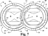
遠位端104には、作業通路130の反対側に壁110から延びる一対のフランジ118及び120を有する。フランジ118及び120は、上述した対応する薄くされた厚さの壁部分114の延長によって形成されるか、その延長部である。好ましい実施形態において、フランジ118及び120は、椎間板のスペースの伸延を行わないが、手順の間損傷からの周囲の血管及び神経構造を保護する。側方フランジは、伸延の構造的な支持を提供しないが、フランジ及び隣接する側壁の材料の厚さは低減される。さらに、遠位端104は、図7に示すように、フランジ118,120の間に配置されたスパイク122、124と、フランジ118,120との間の対向する第3のスパイク126と第4のスパイク128と、を有する。これらのスパイクは、椎体に対して固定された位置でガイドスリーブ100を保持するために隣接する椎体の骨に押される。
【0028】
図4及び図5を参照すると、本発明の他の側面を示すためにガイドスリーブ100の正面図と側面図が示されている。近位端102において、ガイドスリーブ100は、最大幅W1を有する。スリーブ100の遠位端104において、壁110は、幅W1より小さい幅W2を形成する側壁113及び114で小さい厚さを有する。側壁113、114は、全体が平坦ではなく、わずかに曲率を有することが好ましい。側壁113、114は、壁の厚さの低減を行い、側壁113、114の終端で壁全体の厚さまでテーパを有する。壁110の幅の低減は、椎間板のスペースに隣接した領域で血管と神経組織の引込量を低減する。望ましい幅の低減は、装置の必要な強度の低減がほとんどない。なぜならば、ディストラクタ50,80は、ガイドスリーブ100の延長部またはサイドフランジ118,120の代わりに椎体を伸延しその伸延を維持するために使用される。
【0029】
図4及び図9において、軸線L1の周りに形成された第1の作業通路部分107と、軸線L2の周りに形成された第2の作業通路部分109とを有する。これらの作業通路部分107,109は、スリーブ100の長手方向軸線Lの各側に配置されている。作業通路部分107及び109を分離する壁または他の構造はない。作業通路部分107は、長手方向軸線Lとガイドスリーブ100の内面116との間の軸線L1の周りの作業通路130の部分である。同様に、作業通路部分109は、長手方向の軸線Lと内面116との間の軸線L2の周りの作業通路の部分である。したがって、作業通路部分107及び109は、面積が等しく、頭部が切られた円形の形状を有し、各作業通路107及び109の頭部が切られた部分は、互いに隣接して配置されている。
【0030】
図6を参照すると、ガイドスリーブ100作業通路内に並んだ関係で配置されたディストラクタ50及び80を含むディストラクタ/ガイドスリーブ組立体150が示されている。ディストラクタ50,80は、各々が作業通路130の作業通路部分107及び109の対応する1つの作業通路全体または一部を占めるようにスリーブ100内に配置されている。各ディストラクタ50,80は、ガイドスリーブの近位端102から遠位端104に延びている。フランジリング155は、ガイドスリーブ100の近位端の周りに延びているフランジの形態であり、組立体150の挿入中にスリーブ100とディストラクタ50,80との間の相対位置を維持するためにディストラクタ50,80に配置された駆動キャップに接触する。
【0031】
図7を参照すると、併置する関係のディストラクタ50及び80を示す組立体の遠位端104の端面図が示されている。さらに詳細には、ディストラクタ50の軸54は、ディストラクタ軸84の凹形状部分98内に受けられる。また、図面に示されるように、ディストラクタ先端86の凹形状部分96は、ディストラクタ80の長さ方向に延びている凹形状の表面を形成するために凹形状面98と同一平面に延びている。ディストラクタ80の凹形状面は、曲率半径Rを有し、この曲率半径Rは、椎間板のスペースに挿入するためにケージまたは移植部材の直径の約1/2が好ましい。例えば、18mmの直径の移植部材は、約9mmの曲率半径Rを有するディストラクタ80の使用が必要になる。
【0032】
ディストラクタ50がガイドスリーブ100から除去されるとき、ディストラクタ80の凹所領域に隣接しそれに沿うように作業通路130を通って円筒形の作業スペースが形成される。円筒形の作業スペースは、ガイドスリーブ100の凹形状面96,98と内壁116との間に作業通路130の部分を有する。したがって、作業スペースは、作業通路部107全体(図4)と、作業通路部分109の一部とを占める。円筒形作業通路によって占められる作業通路部分109の部分の面積は、斜線が引かれた領域Aによって図7に示されており、以降、重複部分と称する。この重複領域Aは、全体幅の小さいガイドスリーブ100を提供しながら、手順を従来の寸法の器具及び機器を使用してディストラクタ80に隣接して作業スペースで実行することができるようにする。達成される幅の低減の量は、重複領域Aの最大幅である。
【0033】
図8において、ディストラクタ50,80の近位端53,83及びガイドスリーブ100の近位端102から見たガイドスリーブ150の平面図である。1つの実施形態において、ディストラクタ軸54に形成されそこから延びる固定部材140が形成されている。固定部材140は、第1の突出部142と、第2の突出部144とを有する。第1及び第2の突出部142,144は、互いに関してディストラクタ50及び80が回転することを防止するためにディストラクタ80の軸84の凹形状面に形成された対応する切欠き部146,148内に受けられる。また、本発明は、当業者によって理解できるように互いに回転しないようにディストラクタ50及び80に係合する他の機構を考慮することができる。例えば、上述したディストラクタクリップ75は、ディストラクタ50,80を互いに結合するために使用することができる。さらに、ディストラクタ50、80は、固定機構なしで挿入することが考慮される。
【0034】
本発明は、椎間板のスペースへの接近が公知の技術によって行われ、したがって、さらに説明は必要ではない。椎間板のスペースへの接近を得る手順の1つの例は、'917号に開示されている。最初に椎間板のスペースを伸延するためにスタータディストラクタを使用して椎間板のスペースの伸延及び位置決めを考慮する技術を含む他の参考例は、Sofamor Danekによって1999年に発行された「小型機器」と題された外科技術の小冊子に記載されている。また本発明は、当業者によって理解できるように以下の手順及び機器と関連して椎間板のスペースに接近するための他の手順の使用及び用途を考慮している。ここで考慮されるテンプレートは、特定の形状及び寸法を有する移植部材と器具の配置のために必要な面積を画定する。好ましい実施形態において、16mmないし24mmの範囲の直径を有する円筒形移植部材用のテンプレートが提供されるが、ここに使用する移植部材及びテンプレートの他の直径及び制限することなく矩形及び三角形のような他の形状を使用することもできる。
【0035】
脊柱の前方部分への接近は、公知の方法によって達成される。血管、特に大動脈、大静脈、及びその支流は、移植部材を両側に配置するためのスペースを提供するために移動される。テンプレートは、身体に挿入され、ピンが椎間板のスペースに隣接して配置されるまで前進される。テンプレートの周縁は、一対の移植部材を両側に配置するために必要な周縁に対応するように選択される。さらに詳細には、テンプレートの領域が図7に示すようなガイドスリーブの配置するために必要な面積にほぼ等しい。ガイドスリーブは、必ずしも必要ではなく、外科手術場所の組織は、椎間板のスペースがディストラクタ50及び80によって伸延されている間、他の手段によって引き込まれる。外科手順は、ガイドスリーブを使用することなく以下に説明するようなディストラクタ50,80によって形成される作業スペースで実行される。
【0036】
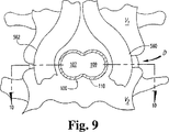
図9を参照すると、ディストラクタ50,80を除去することによって、ガイドスリーブ100を通る断面が提供される。スリーブ100は、2つの隣接する椎体V1とV2との間の椎間板のスペースDに挿入される。ガイドスリーブ100に隣接して大静脈または大動脈の部分を表す血管が配置されている。図10を参照すると、図9の線10-10を通る断面が示されており、ガイドスリーブ100のフランジ118,120が、外科的手順が実行される椎間板のスペースに延びている。フランジ118、120及びスリーブ100は、外科的手順の間使用される椎間板のスペースと器具とを包囲する血管と組織との間の接触を禁止する。スパイク122,124,126及び128は、対応する椎体V1、V2の骨に挿入してもよい。
【0037】
種々の器具及び機器が、ガイドスリーブ100とともに使用可能であり、ガイドスリーブ100はガイドスリーブ100の作業通路130によって形成される作業スペース内でここに示したディストラクタ50,80を含む。これらの器具のいくつかは、Danek社の小冊子及び'917の出願に示されているが、当業者に公知の他の器具も知られている。
【0038】
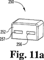
本発明の装置を使用する好ましい方法によれば、図11ないし図22が参照される。図11において、スリーブ組立体は組み立てられ、皮膚を通して椎間板のスペースに挿入される準備がなされる。図11a及び図11bのディストラクタドライバキャップ250は、ディストラクタ50、80の近位端53,83に配置される。図11a及び図11bのディストラクタ駆動キャップ250は、ディストラクタ50,80の近位端53,83に配置される。駆動キャップ250は、ディストラクタ50及び80のフランジポスト53a及び83aを受ける構成のT形状のスロット253及び254を有する本体252を含む。対向するスロット253,254はウインドウ256及び257である。好ましくは、ポスト53a及び83aのフランジ部分は、駆動キャップ250をディストラクタ50,80に固定するために、対応するウインドウ256及び254の1つに、スロット253及び254の上方部分253a及び254aに延びている。
【0039】
使用において、ディストラクタキャップ250は、ディストラクタの先端56,86がフランジ118、120が椎間板のスペースの外側に配置されながら、ディストラクタの先端56,86が椎間板のスペースに駆動されるようにスリーブ100内のディストラクタ50,80のフランジリング155が接触する。ディストラクタキャップ250に加えられる駆動力は、フランジリング155に伝達され、ディストラクタ50,80とともに椎間板のスペースに向かってスリーブ100を駆動する。別の例として、ディストラクタ50、80がガイドスリーブ100に配置されないならば、ディストラクタキャップ250が近位端53,83に固定され、ディストラクタ先端56、86が椎間板のスペースに駆動される。ディストラクタキャップ250は取り除かれ、スリーブ100が挿入されたディストラクタ50,80上に配置され、手順が以下のように連続される。この技術において、クリップ75は、挿入中にディストラクタ50,80を一緒に係合するために使用される。他の変形例において、ディストラクタ50,80を交互に挿入することは、本発明によって禁止される。しかしながら、椎間板のスペースへのディストラクタ50,80の挿入は、ディストラクタ50,80の位置決めを維持できるようにし、互いに関してディストラクタの先端56,86の挿入深さを制御する。
【0040】
図12aにおいて、インパクタキャップ160がフランジリング155上のスリーブ100の近位端102の周りに配置されている。スリーブ100は、ディストラクタ50,80に関して比較的自由に移動する。図12bに示すような椎間板のスペースにすでに配置されたディストラクタ先端56,86に隣接して椎間板のスペースに向かってスリーブ100を駆動しフランジ118及び120を位置決めするようにインパクタキャップ160に駆動力が加えられる。好ましくは、フランジ118及び120は、椎間板のスペースを伸延せず、ディストラクタ50,80がスリーブ100から取り付けられるとき、作業スペースに組織の侵入を防止する。
【0041】
図13に詳細に示され拡大されるように、インパクタキャップ160は、フランジリング155の周りに配置され、フランジリングに接触する。フランジリング155は、種々の寸法のガイドスリーブ100の均一な寸法及び形状が好ましいが、単一のインパクタキャップ160用の種々の寸法のガイドスリーブの各々にモジュラー取付けを行う。インパクタキャップ160は、近位端53,83を受けるための中空の内部161を有する。中空の内側161は、ディストラクタ50,80の位置を維持しながら、椎間板のスペースへのガイドスリーブ100の動きが可能になる十分な深さを有する。
【0042】
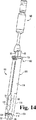
図14において、スラップハンマ165は、椎間板のスペースからディストラクタ50を引くためにディストラクタ50に係合する。図15aにおいて、ディストラクタ50は、スラップハンマ165を使用してスリーブ110の作業通路130から取り外される。凹形状のディストラクタ80のディストラクタ先端86は、連続した作業工程の間に椎間板のスペースの伸延高さを維持するために椎間板のスペースに配置されたままである。他の実施形態において、ディストラクタ80の軸84は、先端部86に取り外し可能に接続され、この場合、軸は、先端部86を所定の位置に残しながら引くこともできる。他の実施形態において、軸84は、椎間板のスペースの領域Aへの装置の挿入回転に対応するために小さい寸法を有する。取り外し可能で小さい直径の軸を使用することによって、先端86のみが凹所領域を必要とする。
【0043】
図15bにおいて、引かれたディストラクタ50は、ハッチが引かれた領域Aによって支持された作業通路部分109と重複部分とから成る作業スペースを残す。したがって、ディストラクタ80の凹形状の表面96,98及びスリーブ110の内面116は、説明するような他の作業手順を完了するために円筒形の作業スペースを形成する。この作業スペースは、移植部材の挿入のために椎間板のスペースを準備するために外科器具を受けるためのガイドスリーブ100に沿った円形の断面を形成する。ディストラクタ50,80の重複形状は、ガイドスリーブ100の幅全体が低減される。
【0044】
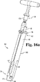
図16aないし図16bにおいて、ガイドスリーブ110を通して配置されたリーマ170が示されている。切削ヘッド171は、椎間板のスペースをリーマ加工するために当業者に公知のねじを有する。図16bに示すようにリーマ170は、ディストラクタの先端86が椎間板のスペースの伸延を維持する間にディストラクタ80に隣接した作業空間内に配置される。ディストラクタの軸84の凹形状面98及びスリーブ110の内面116は、リーマ170の挿入および/又は後退のガイドとして作用する。リーマの深さは、深さ停止部によって制御され、蛍光透視法を介して確認される。
【0045】
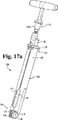
図17aないし図17cにおいて、リーマ170は、ねじが形成された移植部材のスペースを形成するためにヘッド176を備えたタッピング工具175によって引かれ置換される。図17b及び図17cに示すように、タッピング工具175は、ディストラクタ先端86が椎間板のスペースの伸延を維持しながら凹形状のディストラクタ80に隣接した作業空間内に配置される。ディストラクタ80の軸84の凹形状の表面とスリーブ110の内面116は、タッピング工具175の挿入のためのガイドとして作用する。タッピング工具175は、椎間板のスペースのタッピング深さを制御するために深さ停止部を有する。深さと矢の整列は、タッピング加工中に蛍光透視法を使用して確認される。
【0046】
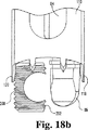
図18aないし図18cにおいて、タッピング工具175は、その遠位端に係合するねじ加工された移植部材200を有する移植挿入装置190によって引かれ置換される。ねじが形成された移植部材200及び挿入装置190は、1つの型式であり、2000年1月11日に出願されたPCT/US00/00590号、2000年1月11日に出願されたPCT/US00/00604、1999年1月11日に出願された60/115,388に示されている。さらに、本発明の移植部材は、少なくとも1つの凹所が形成された側壁を有する限り、他の公知の移植部材及び挿入装置である。移植部材は、生物調和性の材料で形成される。ディストラクタ80の軸84の凹形状面98及びスリーブ110の内面116は、移植部材の椎間板のスペースへの挿入用のガイドとして作用する。
【0047】
インサータ190は、蝶ねじ191を有し、この蝶ねじ191は、インサータ190を介して延びており、移植部材200のスロットが形成された端部201のめねじが形成された開口(図19参照)を介して移植部材200と結合される。図18bの拡大図に示すように移植部材200を回転し、それを椎間板のスペースにねじ込むためにTハンドル192が使用される。図18Cの拡大図にさらにはっきりと示されるように、移植部材200は、凹形状面202がディストラクタ80の凹形状面96に向かって配置されるように挿入される。凹形状面202の位置決めは、挿入装置190とスリーブ100の整列マークを提供することによって確認することができる。さらに、挿入装置190は、移植部材200の椎間板のスペースへのカウンタシンクの支持を行うためにカウンタシンクのマーキング193を含む。移植部材の回転を容易にするために、インサータ190は、遠位端に可動スライドを備えており、この遠位端はねじのために丸い構造を提供する凹形状の表面202の凹所領域を占める。移植部材200が所定の位置にねじ込まれると、遠位先端86は、椎間板のスペースの伸延を維持する。
【0048】
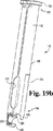
図19aないし図19bにおいて、移植部材200が所望の位置に配置されたとき、移植部材インサータ190は、ガイドスリーブ100から除去され、ディストラクタ先端86は椎間板のスペースから引かれる。好ましくは、椎間板のスペースからディストラクタ先端86を引き、ガイドスリーブ100からディストラクタを引くためにディストラクタ80にスラットハンマ165が係合される。図19bないし図19cに示すようにディストラクタ80は、スリーブ110の作業通路130から取り除かれる。移植部材200は、作業ステップの間椎間板のスペースの伸延高さを維持するために椎間板のスペースに配置されたままである。引かれたディストラクタ80は、作業通路部分107と重複領域Aからなる作業スペースを残す。したがって、移植部材200の凹形状面202とスリーブ110の婦負面116は、以下に示す他の手順のために椎間板のスペースの円筒形の作業スペースを残す。作業スペースは、全体幅を低減しながら移植部材200に隣接する第2の移植部材の挿入用の椎間板のスペースを準備するために従来の寸法の外科手術用器具を受ける円形の断面を形成する。
【0049】
図20aないし図20bにおいて、上述したリーマ170は、ガイドスリーブ110を通して配置される。切断ヘッド171は、椎間板のスペースをリーマ加工するために当業者に公知のねじを有する。図20bに示すように、リーマ170は、移植部材200が椎間板のスペースの伸延を維持しながら移植部材200の凹形状面201に隣接するように作業スペース内に配置される。移植部材200の凹形状面201及びスリーブ110の内面116は、リーマ170の挿入及び動作の案内部材として作用する。
【0050】
図21aないし図21cにおいて、リーマ170は、後退され、第2のねじが形成された移植部材のスペースを準備するためにヘッド176を有する上述したタッピング工具175によって置換される。図21bないし図21cに示すように、タッピング工具175のヘッド176は、移植部材200が椎間板のスペースの伸延を維持する間移植部材200の凹形状面201に隣接した作業スペース内に配置される。凹形状面201及びスリーブ110の内面116は、タッピング工具175の挿入用の案内用部材として作用する。
【0051】
図22aないし図22cにおいて、タッピング工具は後退され、上述した移植部材挿入装置190によって置換され、ねじが形成された移植部材210はその遠位端に係合される。ねじが形成された移植部材210は、拡大図22b及び22cに実線で示すような円形の断面を有するか、または仮想線で示すように凹形状の面を有する移植部材200と同一の断面を有する。いずれの場合においても、移植部材200の凹形状面201は、椎間板のスペースに移植部材210のねじ込み用のガイドとして作用する。
【0052】
もし、移植部材200と同様の移植部材を使用する場合には、凹形状面212が移植部材200の凹形状面202に向かって配置されるように移植部材210を配置することが好ましい。キャビティは骨成長促進材料を詰めることが好ましい。Tハンドル192は、移植部材210を回転するために使用され、図22bに示すように移植部材200に隣接して椎間板のスペースにそれをねじ込む。もし、図22cと同様の円形の移植部材が使用される場合には、移植部材210は、移植部材200の凹形状面201内に配置される。骨成長材料は、移植部材200のキャビティ204と移植部材210のキャビティ213内に配置することができる。
【0053】
ねじが形成された移植部材の使用を主に説明したが、同様に本発明は、椎間板のスペースに押し込み型の移植部材および/又は拡張可能な移植部材の使用を考慮することができる。また、本発明は椎間板のスペース内の両側の場所に2つの移植部材を挿入するために使用されるが、椎間板のスペースへの単一の移植部材の挿入も考慮することができる。
【0054】
もちろん本発明は、椎間板のスペースで実行される種々の手順の深さを測定し制御するための他の深さ停止部及び他の装置を利用することができる。これらの装置及び手順は、Danek社の小冊子及び'917の特許出願にさらに完全に説明されている。さらに、本発明は、上述した器具及び機器とともに使用することには制限されず、ディストラクタ50,80は、本発明が関連する当業者によって他の装置とともに使用されるであろう。
【0055】
本発明を図面と詳細な説明によって説明したが、好ましい実施形態を説明したものであり、変形例及び改造が本発明の範囲内でなされることは理解できよう。
【図面の簡単な説明】
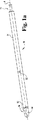
【図1】図1aは、本発明によるディストラクタの斜視図である。
図1bは、図1aのディストラクタの先端の拡大正面図である。
図1cは、図1aのディストラクタの拡大側面図である。
【図2】図2aは、本発明の他の側面によるディストラクタの斜視図である。
図2bは、図2aのディストラクタの先端の拡大正面図である。
図2cは、図2aのディストラクタの先端の拡大側面図である。
【図3】図3は、本発明の他の側面によるガイドスリーブの斜視図である。
【図4】図3のガイドスリーブの正面図である。
【図5】図3のガイドスリーブの側面図である。
【図6】本発明の他の側面によるガイドスリーブ組立体の斜視図である。
【図7】図6のガイドスリーブ組立体の遠位端の拡大端面図である。
【図8】図6のガイドスリーブ組立体の近位端の拡大端面図である。
【図9】図3によるガイドスリーブ組立体の前方から後方を見た図面である。ガイドスリーブ組立体は、一対の隣接した椎体と血管に関連して配置されている。
【図10】図9の線10-10を通る椎間板のスペースの部分断面図である。
【図11】椎間板のスペースにディストラクタを挿入する間のガイドスリーブ組立体の斜視図である。図11a及び図11bは、ディストラクタを椎間板のスペースに駆動するためのディストラクタ駆動キャップの正面図及び後面図である。
【図12】図12a-図12bは、ガイドスリーブを配置する前に配置されたインパクタキャップを備えたガイドスリーブ組立体150の斜視図である。
【図13】インパクタキャップが上に配置されたガイドスリーブ組立体の斜視図である。
【図14】スラップハンマが1つのディストラクタに配置されたガイドスリーブ組立体の斜視図である。
【図15】図15a-図15bは、ディストラクタが取り除かれたガイドスリーブの斜視図及び端面図である。
【図16】図16a-図16bは、リーマがディストラクタに隣接して配置されているガイドスリーブの斜視図及び端面図である。
【図17】図17a-図17cは、タップがディストラクタに隣接して配置されたガイドスリーブ組立体の斜視図、詳細図及び端面図である。
【図18】図18a-図18cは、移植部材がディストラクタに隣接して配置されているガイドスリーブ組立体の斜視図、詳細図及び端面図である。
【図19】図19a-図19cは、他のディストラクタが後退しているガイドスリーブ組立体の斜視図、詳細図及び端面図である。
【図20】図20a-図20cは、移植部材に隣接してリーマが配置されているガイドスリーブ組立体の斜視図、詳細図及び端面図である。
【図21】図21a-図21cは、移植部材に隣接してタッピング工具が配置されているガイドスリーブ組立体の斜視図、詳細図及び端面図である。
【図22】図22a-図22cは、移植部材に隣接して移植部材が配置されているガイドスリーブ組立体の斜視図、詳細図及び端面図である。[0001]
[Technical field to which the invention belongs]
The present invention relates to surgical procedures for stabilizing the spinal column, and more particularly to an instrument for inserting a spinal implant in a space between adjacent vertebrae. More particularly, aspects of the present invention have other uses, but the present invention is particularly useful for inserting an implant into an intervertebral disc space in a surgical procedure that forms an intervertebral disc space and approaches the spinal column from the front. Is suitable.
[0002]
[Prior art]
Various surgical methods for implanting fixation devices in the disc space have been improved. Anterior and posterior surgical methods have been used for intervertebral body fixation. In 1956, Ralph Cloward developed a method and instrument for interbody fusion from the front of the cervical spine. Cloward surgically removes a portion of the intervertebral disc, places a tubular drill guide and prongs with a large foot plate, attaches them on an alignment rod, and then embeds the prongs in the adjacent vertebrae. The drill guide maintains vertebra alignment and facilitates reaming of bone adjacent to the disc space. Reaming creates a hole for receiving a bone dwell graft. The drill guide is removed after the reaming process so that the bone dwell can pass through, but the bone dwell passage has an outer diameter that is significantly larger than the inner diameter of the reamed hole and the drill guide. Removal of the drill guide leaves the dwell insertion state unprotected at all.
[0003]
More recent technology pushes this idea and better protects sensitive tissue during disc space formation and dwell insertion. Such techniques were followed to approach the lumbar spine from the front. An initial opening is made in the disc space, and the height of this space is extended to approximately normal height. Usually, the first distractor is inserted at a measured height by a radiation inspection method. If it is necessary to add a distraction, the first distractor is removed and the second large distractor is inserted. However, since distractor positioning is performed without the benefit of a protective guide sleeve, distractor switching increases the likelihood of neurovascular damage and correspondingly increases surgical time.
[0004]
In a bilateral procedure, a double barrel sleeve is inserted into the distractor and the central extension extends into the disc space to maintain distraction. One limitation with respect to the guide sleeve is the amount of neurovascular retraction that must be achieved to place the guide sleeve in the disc space. Some patients cannot use a double barrel sleeve. This is because there is insufficient space adjacent to the disc space to receive the sleeve assembly. Thus, less neurovascular retraction for proper placement is not necessary and provides great protection for adjacent tissue.
[0005]
Although the techniques described above have advanced, the use of improved instruments and techniques reduces surgical time, reduces the potential for damage to sensitive tissue adjacent to the disc space, and uses protective instruments. Improvements are needed to limit the amount of vascular withdrawal required. The present invention is directed to this need and provides an effective method and apparatus for achieving this need.
[0006]
[Means for Solving the Problems]
The present invention relates to methods and instruments for interbody fusion. In one aspect of the invention, the device forms a reduced width shape that allows insertion from both sides of the implant.
[0007]
In one aspect of the invention, a distractor is provided having a destructor shaft having a length. The tip of the distractor extends from one end of the shaft. The tip of the distractor has opposing first and second surfaces that form the height of the distractor between the two surfaces. The tip of the distractor has a recessed area, preferably a concave surface, extending between the first and second surfaces. The axis of the distractor can include a recessed area along its length that is an extension of the recessed area at the tip of the distractor. The distractor and / or the recessed area of the shaft allows adjacent surgical devices to pass and rotate.
[0008]
In another aspect of the invention, the guide sleeve has a wall that forms a protected passage to the distracted disc space. The guide sleeve has a proximal end and a distal end. A pair of overlapping working passages extend between the ends. The sleeve has a first width at the proximal end and a second width at the distal end. The first width is greater than the second width. The reduced second width is formed by reducing the outer wall thickness of the sleeve at the distal end. Preferably, the first flange and the second flange extend from the distal end with a reduced wall thickness. Preferably, the flange has a thickness corresponding to the reduced wall thickness. More preferably, the first and second lateral extensions have a height that is less than the height of the distracted disc space to inhibit entry of adjacent tissue into the distracted disc space. In other embodiments, the guide sleeve includes a spike protruding from the sleeve distal end between the flanges to engage adjacent vertebral bodies. In other embodiments, the overlapping working passages are cylindrical.
[0009]
In another aspect, a guide sleeve assembly is provided. The guide sleeve assembly includes a sleeve that forms a working passage. The first distractor has a first distractor tip with a recessed area along a portion of its length, and the second distractor has a second distractor tip. By arranging the first distractor in the working path of the sleeve in parallel with the second distractor, the concave surface of the first distractor tip receives at least a part of the second distractor tip. In one embodiment, the recessed region of the first distractor tip is formed by a concave surface, and the second distractor tip has opposing convex surfaces, one of which is the first distractor tip. It is arrange | positioned adjacent to the convex surface of a part. In another form, the first and second distractors form an overlapping region of the guide sleeve working passage.
[0010]
In the method according to the invention, an access to the disc space is obtained. A first distractor having a first distractor tip with a recessed area and a second concave distractor having a second distractor tip, wherein the distractor tip is adjacent to the disc space. Inserted and placed in parallel relationship. Preferably both distractors are arranged within the working diameter of the outer sleeve. The distractor distracts and maintains the disc space at the desired height during the procedure. When distraction to the desired height of the disc space is achieved, the outer sleeve is advanced toward the disc space until it is positioned adjacent to the disc space. If necessary, a drive cap may be placed on the proximal end of the outer sleeve to apply the drive force.
[0011]
The outer sleeve is then driven into position so that the opposing side flanges are placed in the disc space and the outer sleeve spikes enter the vertebral body. Preferably, the side flanges do not perform distraction of the disc space. Once the sleeve is in place, the second distractor is removed, providing a cylindrical working space that penetrates the sleeve to the disc space adjacent to the first distractor. Preferably, the working space defines an area that is greater than 1/2 of the area of the working path of the guide sleeve.
[0012]
Various surgical procedures are performed through the working space such as reaming, tapping and inserting the threaded implant into the disc space. The first graft member is inserted, the second distractor is removed, and the first graft member maintains distraction of the disc space and defines a working space adjacent to the inserted graft member. Preferably, the first implant member has a concave side wall that defines a portion of the cylindrical work space. This surgical procedure is repeated to insert a second graft member adjacent to the first graft member. In one embodiment, the second implant has a circular cross section. In other embodiments, the implant has a cross-section that is mirror image of the cross-section of the first implant after insertion.
[0013]
While various sleeves are known, in a preferred embodiment, the outer sleeve according to the present invention is a reduction adjacent to the bone engaging distal end to limit the amount of surrounding vascular and neural tissue withdrawal required for the procedure. With a portion of the specified width. The reduced width portion, which is preferably combined with the previously described overlapping working path, significantly reduces the overall width of the sleeve. In a preferred embodiment, the sleeve assembly has a pair of opposing side flanges having a first height, i.e., lateral extensions. The lateral extensions prevent tissue from entering the working area of the disc space. Preferably, the side flanges of the outer sleeve are not used to minimize the distraction of the disc space and are not subject to the distraction force of the disc space. As a result, the flange and adjacent sidewalls have a reduced wall thickness.
[0014]
Yet another aspect includes providing a viewing window along the centerline of the outer sleeve to allow viewing of the inner working channel while the instrument is in the working channel. Even without the use of an imaging device, the present invention contemplates the use of a manually adjustable depth stop to control the steps of drilling, reaming, tapping, and implanting member insertion. As used herein, the term “implant” is used in a broad sense throughout this specification and is used for bone dowels, metal cages, spacers, etc. used for intervertebral body fixation regardless of the shape or material of the structure. Includes grafts.
[0015]
Related objects, aspects, shapes and features of the present invention will become apparent from the following detailed description.
[0016]
DETAILED DESCRIPTION OF THE INVENTION
In order to facilitate an understanding of the principles of the invention, reference will be made to the embodiments illustrated in the drawings and specific language will be used to describe the embodiments. However, it is not intended to limit the scope of the invention, variations and other modifications of the apparatus shown are contemplated, and other uses of the principles of the invention as illustrated are contemplated by those skilled in the art. Can understand.
[0017]
The present invention relates to a method and apparatus for performing interbody fusion. In particular, while aspects of the present invention are used alone or in combination, the devices and methods disclosed herein are particularly effective for anterior lumbar interbody fusion. However, the surgical instruments and methods of the present invention are not limited to such methods and can be used for side and anterior side access to the spinal column. The surgical instrument and method of the present invention can also be used in areas other than the entire vertebral body portion of the spine and spinal surgical procedures.
[0018]
Referring to FIGS. 1a to 1c, a convex first
[0019]
The flat surfaces 60 and 61 are aligned in parallel along the longitudinal axis A of the
[0020]
Referring to FIGS. 2a-2c, there is shown a second
[0021]
The flat surfaces 90 and 91 are at the longitudinal axis B of the
[0022]
[0023]
In particular, there is no limit, but the
[0024]
Referring to FIG. 3, a
[0025]
The
[0026]
[0027]
The
[0028]
4 and 5, a front view and a side view of the
[0029]
4 and 9, it has a first working
[0030]
Referring to FIG. 6, a distractor /
[0031]
Referring to FIG. 7, an end view of the
[0032]
When the
[0033]
FIG. 9 is a plan view of the
[0034]
The present invention provides access to the intervertebral disc space by known techniques and therefore does not require further explanation. One example of a procedure for gaining access to intervertebral disc space is disclosed in '917. Other reference examples, including a technique that initially uses a starter distractor to distract and position the disc space, to distract the disc space, include the “small instrument” published in 1999 by Sofamor Danek. It is described in the book entitled Surgical Technique. The present invention also contemplates the use and application of other procedures for accessing the disc space in conjunction with the following procedures and instruments, as will be appreciated by those skilled in the art. The template considered here defines the area required for placement of implants and devices having specific shapes and dimensions. In a preferred embodiment, a template for a cylindrical implant having a diameter in the range of 16 mm to 24 mm is provided, such as other diameters of the implant and template used herein and without limitation such as rectangular and triangular Other shapes can also be used.
[0035]
Access to the anterior portion of the spine is accomplished by known methods. The blood vessels, particularly the aorta, vena cava, and their tributaries are moved to provide space for placing the implant on both sides. The template is inserted into the body and advanced until the pins are placed adjacent to the disc space. The periphery of the template is selected to correspond to the periphery required to place the pair of implants on both sides. More specifically, the area of the template is approximately equal to the area required for placement of the guide sleeve as shown in FIG. A guide sleeve is not necessary and the tissue at the surgical site is drawn by other means while the disc space is distracted by the
[0036]
Referring to FIG. 9, by removing the
[0037]
Various instruments and equipment can be used with the
[0038]
In accordance with a preferred method of using the apparatus of the present invention, reference is made to FIGS. In FIG. 11, the sleeve assembly is assembled and ready to be inserted through the skin into the disc space. The
[0039]
In use, the
[0040]
In FIG. 12 a, an
[0041]
As shown in detail in FIG. 13 and enlarged, the
[0042]
In FIG. 14, the
[0043]
In FIG. 15b, the drawn
[0044]
In FIGS. 16a-16b, a
[0045]
In FIGS. 17a-17c, the
[0046]
In FIGS. 18a-18c, the
[0047]
The
[0048]
19a-19b, when the
[0049]
20A to 20B, the above-described
[0050]
In FIGS. 21a-21c, the
[0051]
22a-22c, the tapping tool is retracted and replaced by the
[0052]
If an implant similar to the
[0053]
Although the use of a threaded implant has been primarily described, the present invention can similarly contemplate the use of a push-in implant and / or an expandable implant in the disc space. Also, although the present invention is used to insert two implants at locations on both sides within the disc space, insertion of a single implant into the disc space can also be considered.
[0054]
Of course, the present invention may utilize other depth stops and other devices for measuring and controlling the depth of various procedures performed in the disc space. These devices and procedures are more fully described in the Danek brochure and the '917 patent application. Further, the present invention is not limited to use with the instruments and equipment described above, and the
[0055]
Although the present invention has been described with reference to the drawings and detailed description, it is to be understood that the preferred embodiments have been described and that variations and modifications can be made within the scope of the present invention.
[Brief description of the drawings]
FIG. 1a is a perspective view of a distractor according to the present invention.
FIG. 1b is an enlarged front view of the tip of the distractor of FIG. 1a.
FIG. 1c is an enlarged side view of the distractor of FIG. 1a.
FIG. 2a is a perspective view of a distractor according to another aspect of the present invention.
FIG. 2b is an enlarged front view of the tip of the distractor of FIG. 2a.
FIG. 2c is an enlarged side view of the tip of the distractor of FIG. 2a.
FIG. 3 is a perspective view of a guide sleeve according to another aspect of the present invention.
4 is a front view of the guide sleeve of FIG. 3;
FIG. 5 is a side view of the guide sleeve of FIG. 3;
FIG. 6 is a perspective view of a guide sleeve assembly according to another aspect of the present invention.
7 is an enlarged end view of the distal end of the guide sleeve assembly of FIG. 6. FIG.
FIG. 8 is an enlarged end view of the proximal end of the guide sleeve assembly of FIG.
9 is a view of the guide sleeve assembly according to FIG. 3 as viewed from the front to the rear. The guide sleeve assembly is disposed in relation to a pair of adjacent vertebral bodies and blood vessels.
10 is a partial cross-sectional view of the intervertebral disc space through line 10-10 of FIG. 9. FIG.
FIG. 11 is a perspective view of the guide sleeve assembly during insertion of the distractor into the disc space. 11a and 11b are front and rear views of a distractor drive cap for driving the distractor into the disc space.
FIGS. 12a-12b are perspective views of a
FIG. 13 is a perspective view of a guide sleeve assembly with an impactor cap disposed thereon.
FIG. 14 is a perspective view of a guide sleeve assembly in which a slap hammer is disposed on one distractor.
FIGS. 15a-15b are perspective and end views of a guide sleeve with the distractor removed. FIGS.
FIGS. 16a-16b are perspective and end views of a guide sleeve with a reamer positioned adjacent to a distractor. FIGS.
FIGS. 17a-17c are perspective, detailed and end views of a guide sleeve assembly with taps located adjacent to the distractor. FIGS.
FIGS. 18a-18c are perspective, detailed and end views of a guide sleeve assembly in which the implant is positioned adjacent to the distractor. FIGS.
FIGS. 19a-19c are a perspective view, a detail view and an end view of a guide sleeve assembly with another distractor retracted. FIGS.
FIGS. 20a-20c are a perspective view, a detailed view and an end view of a guide sleeve assembly with a reamer disposed adjacent to an implant. FIGS.
FIGS. 21a-21c are perspective, detailed and end views of a guide sleeve assembly with a tapping tool positioned adjacent to the implant.
FIGS. 22a-22c are a perspective view, a detail view, and an end view of a guide sleeve assembly in which the graft member is positioned adjacent to the graft member. FIGS.
Claims (31)
所定の長さを有する第1のディストラクタ(80)であって、第1の軸(84)及びその軸の末端における第1のディストラクタ先端(86)を有する第1のディストラクタを備え、前記第1のディストラクタ先端(86)が、
第1の伸延高さ(72’)を形成する第1の表面(90)及び対向する第2の表面(91)と、
前記所定の長さの少なくとも一部に沿って前記第1の表面及び前記第2の表面の間に延びる凹所領域(96)と、
前記凹所領域(96)に対して対向する対向表面(94)とを備え、
前記第1のディストラクタ先端(86)が、その凹所領域(96)及び前記対向表面(94)の間の所定の幅(74)を有し、この所定の幅(74)が、前記第1の伸延高さ(72’)と少なくとも同じ大きさの断面直径を有する前記脊柱の椎間板のスペース内の概ね円筒形の移植部材の移植部材挿入場所を実質的に占めるような寸法である、器具。In a surgical instrument for distracting the spinal disc space,
A first distractor with a predetermined length (80) comprises a first distractor having a first distractor tip in the first axis (84) and ends of the shaft (86), The first distractor tip (86) is
A first surface (90) forming a first distraction height (72 ') and an opposing second surface (91);
Concave Plant area (96) extending between said predetermined length of at least a portion along said first surface and said second surface,
An opposing surface (94) facing the recessed area (96) ,
The first distractor tip (86) has a predetermined width (74) between its recessed area (96) and the opposing surface (94), the predetermined width (74) being An instrument that is dimensioned to substantially occupy the implant insertion location of a generally cylindrical implant in the intervertebral disc space having a cross-sectional diameter at least as great as a distraction height (72 ') of 1 .
第1の軸(84)と前記第1の軸から延びる第1のディストラクタ先端(86)を備えた第1のディストラクタ(80)であって、前記第1のディストラクタ先端(86)が、第1の伸延高さ(72’)を形成する対向する第1の表面(90)及び第2の表面(91)を有し、前記第1の表面及び前記第2の表面の間に延びる凹所領域(96)を有する第1のディストラクタ(80)と、
第2の軸(54)と前記第2の軸から延びる第2のディストラクタ先端(56)を備えた第2のディストラクタ(50)であって、前記第2のディストラクタ先端(56)が、第1の伸延高さ(72’)と等しい第2の伸延高さ(72)を形成する対向する第1の表面(60)及び第2の表面(61)を有する第2のディストラクタ(50)と、
作業通路(130)を形成する壁を有するガイドスリーブ(100)とを備え、
前記第1のディストラクタ(80)及び前記第2のディストラクタ(50)が、前記ガイドスリーブの前記作業通路(130)に受けられる、器具。In a surgical instrument for distracting the spinal disc space,
A first distractor (80) comprising a first shaft (84) and a first distractor tip (86) extending from the first shaft, wherein the first distractor tip (86) , Having opposing first surface (90) and second surface (91) forming a first distraction height (72 ′) and extending between the first surface and the second surface A first distractor (80) having a recessed area (96);
A second distractor (50) comprising a second shaft (54) and a second distractor tip (56) extending from the second shaft, wherein the second distractor tip (56) a second distractor having a first distraction height (72 ') equal to the first surface (60) facing to form a second distraction height (72) and a second surface (61) ( 50),
A guide sleeve (100) having a wall forming a working channel (130),
An instrument wherein the first distractor (80) and the second distractor (50) are received in the working channel (130) of the guide sleeve.
Applications Claiming Priority (3)
| Application Number | Priority Date | Filing Date | Title |
|---|---|---|---|
| US11879399P | 1999-02-04 | 1999-02-04 | |
| US60/118,793 | 1999-02-04 | ||
| PCT/US2000/002942 WO2000045709A1 (en) | 1999-02-04 | 2000-02-03 | Methods and instrumentation for vertebral interbody fusion |
Publications (3)
| Publication Number | Publication Date |
|---|---|
| JP2002536043A JP2002536043A (en) | 2002-10-29 |
| JP2002536043A5 JP2002536043A5 (en) | 2008-07-31 |
| JP4243026B2 true JP4243026B2 (en) | 2009-03-25 |
Family
ID=22380775
Family Applications (1)
| Application Number | Title | Priority Date | Filing Date |
|---|---|---|---|
| JP2000596835A Expired - Fee Related JP4243026B2 (en) | 1999-02-04 | 2000-02-03 | Surgical instruments |
Country Status (6)
| Country | Link |
|---|---|
| US (2) | US6575981B1 (en) |
| EP (1) | EP1152697A1 (en) |
| JP (1) | JP4243026B2 (en) |
| AU (1) | AU761818C (en) |
| CA (1) | CA2361069A1 (en) |
| WO (1) | WO2000045709A1 (en) |
Families Citing this family (93)
| Publication number | Priority date | Publication date | Assignee | Title |
|---|---|---|---|---|
| US6743234B2 (en) | 1999-02-04 | 2004-06-01 | Sdgi Holdings, Inc. | Methods and instrumentation for vertebral interbody fusion |
| WO2003026514A1 (en) * | 1999-02-04 | 2003-04-03 | Sdgi Holdings, Inc, | Methods and instrumentation for vertebral interbody fusion |
| US6648895B2 (en) * | 2000-02-04 | 2003-11-18 | Sdgi Holdings, Inc. | Methods and instrumentation for vertebral interbody fusion |
| US6241770B1 (en) * | 1999-03-05 | 2001-06-05 | Gary K. Michelson | Interbody spinal fusion implant having an anatomically conformed trailing end |
| CA2363562C (en) * | 1999-05-05 | 2010-08-03 | Gary Karlin Michelson | Nested interbody spinal fusion implants |
| WO2001013807A2 (en) | 1999-08-26 | 2001-03-01 | Sdgi Holdings, Inc. | Devices and methods for implanting fusion cages |
| US6575899B1 (en) | 1999-10-20 | 2003-06-10 | Sdgi Holdings, Inc. | Methods and instruments for endoscopic interbody surgical techniques |
| US7462195B1 (en) | 2000-04-19 | 2008-12-09 | Warsaw Orthopedic, Inc. | Artificial lumbar interbody spinal implant having an asymmetrical leading end |
| US6350283B1 (en) * | 2000-04-19 | 2002-02-26 | Gary K. Michelson | Bone hemi-lumbar interbody spinal implant having an asymmetrical leading end and method of installation thereof |
| US6478800B1 (en) | 2000-05-08 | 2002-11-12 | Depuy Acromed, Inc. | Medical installation tool |
| US6599291B1 (en) | 2000-10-20 | 2003-07-29 | Sdgi Holdings, Inc. | Methods and instruments for interbody surgical techniques |
| US6890355B2 (en) | 2001-04-02 | 2005-05-10 | Gary K. Michelson | Artificial contoured spinal fusion implants made of a material other than bone |
| US6989031B2 (en) * | 2001-04-02 | 2006-01-24 | Sdgi Holdings, Inc. | Hemi-interbody spinal implant manufactured from a major long bone ring or a bone composite |
| US7074226B2 (en) * | 2002-09-19 | 2006-07-11 | Sdgi Holdings, Inc. | Oval dilator and retractor set and method |
| WO2004032807A2 (en) * | 2002-10-08 | 2004-04-22 | Sdgi Holdings, Inc. | Insertion device and techniques for orthopaedic implants |
| WO2004084742A1 (en) | 2003-03-24 | 2004-10-07 | Theken Surgical Llc | Spinal implant adjustment device |
| US7491204B2 (en) | 2003-04-28 | 2009-02-17 | Spine Solutions, Inc. | Instruments and method for preparing an intervertebral space for receiving an artificial disc implant |
| US7625379B2 (en) * | 2004-01-26 | 2009-12-01 | Warsaw Orthopedic, Inc. | Methods and instrumentation for inserting intervertebral grafts and devices |
| US20050197661A1 (en) * | 2004-03-03 | 2005-09-08 | Scimed Life Systems, Inc. | Tissue removal probe with sliding burr in cutting window |
| US20050209610A1 (en) * | 2004-03-03 | 2005-09-22 | Scimed Life Systems, Inc. | Radially adjustable tissue removal device |
| US8784421B2 (en) | 2004-03-03 | 2014-07-22 | Boston Scientific Scimed, Inc. | Apparatus and methods for removing vertebral bone and disc tissue |
| US20050209622A1 (en) * | 2004-03-03 | 2005-09-22 | Scimed Life Systems, Inc. | Tissue removal probe with irrigation and aspiration ports |
| US20050240197A1 (en) * | 2004-04-23 | 2005-10-27 | Kmiec Stanley J Jr | Device and method for inserting, positioning and removing an implant |
| US7033363B2 (en) * | 2004-05-19 | 2006-04-25 | Sean Powell | Snap-lock for drill sleeve |
| US7862617B2 (en) * | 2004-07-27 | 2011-01-04 | Lamprich Medical, Llc | Spinal disc prosthesis apparatus and placement method |
| US7172628B2 (en) * | 2004-07-27 | 2007-02-06 | Lonnie Jay Lamprich | Spinal disc prosthesis and methods |
| US20060036261A1 (en) * | 2004-08-13 | 2006-02-16 | Stryker Spine | Insertion guide for a spinal implant |
| US7776045B2 (en) * | 2004-08-20 | 2010-08-17 | Warsaw Orthopedic, Inc. | Instrumentation and methods for vertebral distraction |
| DE102004043996B4 (en) * | 2004-09-08 | 2008-04-17 | Aesculap Ag & Co. Kg | Surgical instrument and implant system |
| US7799081B2 (en) | 2004-09-14 | 2010-09-21 | Aeolin, Llc | System and method for spinal fusion |
| US7763024B2 (en) * | 2004-09-23 | 2010-07-27 | Spine Solutions, Inc. | Adjustable cutting of cutout in vertebral bone |
| US8409282B2 (en) | 2004-10-20 | 2013-04-02 | Vertiflex, Inc. | Systems and methods for posterior dynamic stabilization of the spine |
| US8317864B2 (en) | 2004-10-20 | 2012-11-27 | The Board Of Trustees Of The Leland Stanford Junior University | Systems and methods for posterior dynamic stabilization of the spine |
| US8425559B2 (en) | 2004-10-20 | 2013-04-23 | Vertiflex, Inc. | Systems and methods for posterior dynamic stabilization of the spine |
| US8123782B2 (en) | 2004-10-20 | 2012-02-28 | Vertiflex, Inc. | Interspinous spacer |
| US7763074B2 (en) | 2004-10-20 | 2010-07-27 | The Board Of Trustees Of The Leland Stanford Junior University | Systems and methods for posterior dynamic stabilization of the spine |
| US8152837B2 (en) | 2004-10-20 | 2012-04-10 | The Board Of Trustees Of The Leland Stanford Junior University | Systems and methods for posterior dynamic stabilization of the spine |
| US8123807B2 (en) | 2004-10-20 | 2012-02-28 | Vertiflex, Inc. | Systems and methods for posterior dynamic stabilization of the spine |
| US9023084B2 (en) | 2004-10-20 | 2015-05-05 | The Board Of Trustees Of The Leland Stanford Junior University | Systems and methods for stabilizing the motion or adjusting the position of the spine |
| US8613747B2 (en) | 2004-10-20 | 2013-12-24 | Vertiflex, Inc. | Spacer insertion instrument |
| US8128662B2 (en) | 2004-10-20 | 2012-03-06 | Vertiflex, Inc. | Minimally invasive tooling for delivery of interspinous spacer |
| US8945183B2 (en) | 2004-10-20 | 2015-02-03 | Vertiflex, Inc. | Interspinous process spacer instrument system with deployment indicator |
| US8012207B2 (en) | 2004-10-20 | 2011-09-06 | Vertiflex, Inc. | Systems and methods for posterior dynamic stabilization of the spine |
| US8167944B2 (en) | 2004-10-20 | 2012-05-01 | The Board Of Trustees Of The Leland Stanford Junior University | Systems and methods for posterior dynamic stabilization of the spine |
| US8277488B2 (en) | 2004-10-20 | 2012-10-02 | Vertiflex, Inc. | Interspinous spacer |
| US9161783B2 (en) | 2004-10-20 | 2015-10-20 | Vertiflex, Inc. | Interspinous spacer |
| US8273108B2 (en) | 2004-10-20 | 2012-09-25 | Vertiflex, Inc. | Interspinous spacer |
| US9119680B2 (en) | 2004-10-20 | 2015-09-01 | Vertiflex, Inc. | Interspinous spacer |
| US20060089649A1 (en) * | 2004-10-26 | 2006-04-27 | Ullrich Peter F Jr | Surgical instruments and method of using same |
| EP1814474B1 (en) | 2004-11-24 | 2011-09-14 | Samy Abdou | Devices for inter-vertebral orthopedic device placement |
| EP2219538B1 (en) | 2004-12-06 | 2022-07-06 | Vertiflex, Inc. | Spacer insertion instrument |
| US9271843B2 (en) | 2005-09-27 | 2016-03-01 | Henry F. Fabian | Spine surgery method and implant |
| US8236058B2 (en) | 2005-09-27 | 2012-08-07 | Fabian Henry F | Spine surgery method and implant |
| US20070100366A1 (en) * | 2005-10-28 | 2007-05-03 | Sara Dziedzic | Minimally invasive tissue expander systems and methods |
| US20070123903A1 (en) * | 2005-10-31 | 2007-05-31 | Depuy Spine, Inc. | Medical Device installation tool and methods of use |
| US20070123904A1 (en) * | 2005-10-31 | 2007-05-31 | Depuy Spine, Inc. | Distraction instrument and method for distracting an intervertebral site |
| US7867237B2 (en) * | 2005-10-31 | 2011-01-11 | Depuy Spine, Inc. | Arthroplasty revision device and method |
| US8377072B2 (en) * | 2006-02-06 | 2013-02-19 | Depuy Spine, Inc. | Medical device installation tool |
| US8066714B2 (en) | 2006-03-17 | 2011-11-29 | Warsaw Orthopedic Inc. | Instrumentation for distraction and insertion of implants in a spinal disc space |
| US7615079B2 (en) * | 2006-04-20 | 2009-11-10 | Meditech Advisors, Llc | Monorail system |
| US8303601B2 (en) | 2006-06-07 | 2012-11-06 | Stryker Spine | Collet-activated distraction wedge inserter |
| US8998990B2 (en) | 2006-07-24 | 2015-04-07 | DePuy Synthes Products, LLC | Intervertebral implant with keel |
| WO2008016872A2 (en) | 2006-07-31 | 2008-02-07 | Synthes (U.S.A.) | Drilling/milling guide and keel cut preparation system |
| US8845726B2 (en) | 2006-10-18 | 2014-09-30 | Vertiflex, Inc. | Dilator |
| JP5271281B2 (en) * | 2007-02-09 | 2013-08-21 | アルファテック スパイン, インコーポレイテッド | Curved spine access method and device |
| WO2008130564A1 (en) * | 2007-04-16 | 2008-10-30 | Vertiflex Inc. | Interspinous spacer |
| US8070754B2 (en) | 2007-05-31 | 2011-12-06 | Fabian Henry F | Spine surgery method and instrumentation |
| WO2009091922A2 (en) | 2008-01-15 | 2009-07-23 | Vertiflex, Inc. | Interspinous spacer |
| US8449554B2 (en) * | 2008-03-07 | 2013-05-28 | K2M, Inc. | Intervertebral implant and instrument with removable section |
| US20090270873A1 (en) | 2008-04-24 | 2009-10-29 | Fabian Henry F | Spine surgery method and inserter |
| EP2451403B1 (en) | 2009-07-09 | 2016-04-27 | R Tree Innovations, LLC | System for insertion of an inter-body implant device |
| US10098674B2 (en) | 2009-10-22 | 2018-10-16 | Nuvasive, Inc. | System and method for posterior cervical fusion |
| WO2011050140A1 (en) | 2009-10-22 | 2011-04-28 | Blue Fury Consulting, L.L.C. | Posterior cervical fusion system and techniques |
| US8979748B2 (en) * | 2009-10-23 | 2015-03-17 | James L. Chappuis | Devices and methods for temporarily retaining spinal rootlets within dural sac |
| US8764806B2 (en) | 2009-12-07 | 2014-07-01 | Samy Abdou | Devices and methods for minimally invasive spinal stabilization and instrumentation |
| EP2512357B1 (en) | 2009-12-15 | 2016-07-13 | Vertiflex, Inc. | Spinal spacer for cervical and other vertebra, and associated systems |
| CN102892387B (en) | 2010-03-16 | 2016-03-16 | 品尼高脊柱集团有限责任公司 | Intervertebral implant and graft induction system and method |
| US9358122B2 (en) | 2011-01-07 | 2016-06-07 | K2M, Inc. | Interbody spacer |
| US8845728B1 (en) | 2011-09-23 | 2014-09-30 | Samy Abdou | Spinal fixation devices and methods of use |
| US9380932B1 (en) | 2011-11-02 | 2016-07-05 | Pinnacle Spine Group, Llc | Retractor devices for minimally invasive access to the spine |
| US20130226240A1 (en) | 2012-02-22 | 2013-08-29 | Samy Abdou | Spinous process fixation devices and methods of use |
| US9198767B2 (en) | 2012-08-28 | 2015-12-01 | Samy Abdou | Devices and methods for spinal stabilization and instrumentation |
| US9320617B2 (en) | 2012-10-22 | 2016-04-26 | Cogent Spine, LLC | Devices and methods for spinal stabilization and instrumentation |
| US10070970B2 (en) | 2013-03-14 | 2018-09-11 | Pinnacle Spine Group, Llc | Interbody implants and graft delivery systems |
| US9675303B2 (en) | 2013-03-15 | 2017-06-13 | Vertiflex, Inc. | Visualization systems, instruments and methods of using the same in spinal decompression procedures |
| US9486256B1 (en) | 2013-03-15 | 2016-11-08 | Nuvasive, Inc. | Rod reduction assemblies and related methods |
| AU2015256024B2 (en) | 2014-05-07 | 2020-03-05 | Vertiflex, Inc. | Spinal nerve decompression systems, dilation systems, and methods of using the same |
| US10857003B1 (en) | 2015-10-14 | 2020-12-08 | Samy Abdou | Devices and methods for vertebral stabilization |
| US10973648B1 (en) | 2016-10-25 | 2021-04-13 | Samy Abdou | Devices and methods for vertebral bone realignment |
| US10744000B1 (en) | 2016-10-25 | 2020-08-18 | Samy Abdou | Devices and methods for vertebral bone realignment |
| US11051861B2 (en) | 2018-06-13 | 2021-07-06 | Nuvasive, Inc. | Rod reduction assemblies and related methods |
| US11179248B2 (en) | 2018-10-02 | 2021-11-23 | Samy Abdou | Devices and methods for spinal implantation |
| US11883303B2 (en) | 2019-12-30 | 2024-01-30 | Vertebration, Inc. | Spine surgery method and instrumentation |
Family Cites Families (46)
| Publication number | Priority date | Publication date | Assignee | Title |
|---|---|---|---|---|
| EP0703757B1 (en) | 1988-06-13 | 2003-08-27 | Karlin Technology, Inc. | Apparatus for inserting spinal implants |
| US5015247A (en) | 1988-06-13 | 1991-05-14 | Michelson Gary K | Threaded spinal implant |
| US5593409A (en) | 1988-06-13 | 1997-01-14 | Sofamor Danek Group, Inc. | Interbody spinal fusion implants |
| US6210412B1 (en) | 1988-06-13 | 2001-04-03 | Gary Karlin Michelson | Method for inserting frusto-conical interbody spinal fusion implants |
| US5484437A (en) | 1988-06-13 | 1996-01-16 | Michelson; Gary K. | Apparatus and method of inserting spinal implants |
| US6123705A (en) | 1988-06-13 | 2000-09-26 | Sdgi Holdings, Inc. | Interbody spinal fusion implants |
| US7534254B1 (en) | 1988-06-13 | 2009-05-19 | Warsaw Orthopedic, Inc. | Threaded frusto-conical interbody spinal fusion implants |
| US5772661A (en) | 1988-06-13 | 1998-06-30 | Michelson; Gary Karlin | Methods and instrumentation for the surgical correction of human thoracic and lumbar spinal disease from the antero-lateral aspect of the spine |
| US5015255A (en) | 1989-05-10 | 1991-05-14 | Spine-Tech, Inc. | Spinal stabilization method |
| US5055104A (en) * | 1989-11-06 | 1991-10-08 | Surgical Dynamics, Inc. | Surgically implanting threaded fusion cages between adjacent low-back vertebrae by an anterior approach |
| US5865834A (en) | 1991-12-13 | 1999-02-02 | Mcguire; David A. | Coring reamer |
| US5269772A (en) | 1992-01-24 | 1993-12-14 | Wilk Peter J | Laparoscopic cannula assembly and associated method |
| AU683243B2 (en) | 1993-02-10 | 1997-11-06 | Zimmer Spine, Inc. | Spinal stabilization surgical tool set |
| DE4328690B4 (en) | 1993-08-26 | 2006-08-17 | SDGI Holdings, Inc., Wilmington | Intervertebral implant for vertebral body blocking and implantation instrument for positioning the intervertebral implant |
| US5514180A (en) | 1994-01-14 | 1996-05-07 | Heggeness; Michael H. | Prosthetic intervertebral devices |
| US5431658A (en) | 1994-02-14 | 1995-07-11 | Moskovich; Ronald | Facilitator for vertebrae grafts and prostheses |
| AU695466B2 (en) | 1994-05-23 | 1998-08-13 | Zimmer Spine, Inc. | Intervertebral fusion implant |
| US5569205A (en) | 1994-07-14 | 1996-10-29 | Hart; Charles C. | Multiport trocar |
| US6033405A (en) | 1994-09-15 | 2000-03-07 | Surgical Dynamics, Inc. | Apparatus and method for implant insertion |
| US5885299A (en) | 1994-09-15 | 1999-03-23 | Surgical Dynamics, Inc. | Apparatus and method for implant insertion |
| CA2203568A1 (en) | 1994-10-24 | 1996-05-02 | Smith & Nephew Endoscopy, Inc. | Hollow surgical cutter with apertured flutes |
| US5766252A (en) | 1995-01-24 | 1998-06-16 | Osteonics Corp. | Interbody spinal prosthetic implant and method |
| US5556399A (en) | 1995-02-14 | 1996-09-17 | Huebner; Randall J. | Bone-harvesting drill apparatus and method for its use |
| CA2199462C (en) | 1996-03-14 | 2006-01-03 | Charles J. Winslow | Method and instrumentation for implant insertion |
| US6159214A (en) | 1996-07-31 | 2000-12-12 | Michelson; Gary K. | Milling instrumentation and method for preparing a space between adjacent vertebral bodies |
| US6063088A (en) | 1997-03-24 | 2000-05-16 | United States Surgical Corporation | Method and instrumentation for implant insertion |
| US5968098A (en) | 1996-10-22 | 1999-10-19 | Surgical Dynamics, Inc. | Apparatus for fusing adjacent bone structures |
| US6120506A (en) | 1997-03-06 | 2000-09-19 | Sulzer Spine-Tech Inc. | Lordotic spinal implant |
| US6042582A (en) | 1997-05-20 | 2000-03-28 | Ray; Charles D. | Instrumentation and method for facilitating insertion of spinal implant |
| CA2238117C (en) * | 1997-05-30 | 2006-01-10 | United States Surgical Corporation | Method and instrumentation for implant insertion |
| FR2767675B1 (en) | 1997-08-26 | 1999-12-03 | Materiel Orthopedique En Abreg | INTERSOMATIC IMPLANT AND ANCILLARY OF PREPARATION SUITABLE FOR ALLOWING ITS POSITION |
| US6086595A (en) | 1997-08-29 | 2000-07-11 | Sulzer Spine-Tech Inc. | Apparatus and method for spinal stabilization |
| US6059790A (en) | 1997-08-29 | 2000-05-09 | Sulzer Spine-Tech Inc. | Apparatus and method for spinal stabilization |
| US6004326A (en) | 1997-09-10 | 1999-12-21 | United States Surgical | Method and instrumentation for implant insertion |
| JP3321553B2 (en) | 1997-10-08 | 2002-09-03 | 松下電器産業株式会社 | Method for manufacturing Bi-CMOS integrated circuit device |
| ATE274844T1 (en) * | 1998-04-09 | 2004-09-15 | Sdgi Holdings Inc | VERTEBRATE BODY DISTRACTOR |
| US6197033B1 (en) * | 1998-04-09 | 2001-03-06 | Sdgi Holdings, Inc. | Guide sleeve for offset vertebrae |
| US6171339B1 (en) * | 1998-05-19 | 2001-01-09 | Sulzer Spine-Tech Inc. | Multi-lumen spinal implant guide and method |
| US6174311B1 (en) | 1998-10-28 | 2001-01-16 | Sdgi Holdings, Inc. | Interbody fusion grafts and instrumentation |
| US6228022B1 (en) * | 1998-10-28 | 2001-05-08 | Sdgi Holdings, Inc. | Methods and instruments for spinal surgery |
| JP2002534211A (en) | 1999-01-11 | 2002-10-15 | エスディージーアイ・ホールディングス・インコーポレーテッド | Intervertebral fixation spacer |
| DE60044258D1 (en) | 1999-01-25 | 2010-06-02 | Warsaw Orthopedic Inc | INSTRUMENT FOR CREATING AN INTERMEDIATELY ROOM FOR THE RECORDING OF AN IMPLANT |
| US6648895B2 (en) * | 2000-02-04 | 2003-11-18 | Sdgi Holdings, Inc. | Methods and instrumentation for vertebral interbody fusion |
| US6056749A (en) | 1999-03-15 | 2000-05-02 | Spineology, Inc. | Method and device for fixing and correcting spondylolisthesis anteriorly |
| US6113602A (en) | 1999-03-26 | 2000-09-05 | Sulzer Spine-Tech Inc. | Posterior spinal instrument guide and method |
| US6224599B1 (en) | 1999-05-19 | 2001-05-01 | Matthew G. Baynham | Viewable wedge distractor device |
-
2000
- 2000-02-03 WO PCT/US2000/002942 patent/WO2000045709A1/en active IP Right Grant
- 2000-02-03 CA CA002361069A patent/CA2361069A1/en not_active Abandoned
- 2000-02-03 JP JP2000596835A patent/JP4243026B2/en not_active Expired - Fee Related
- 2000-02-03 EP EP00908487A patent/EP1152697A1/en not_active Withdrawn
- 2000-02-03 AU AU29819/00A patent/AU761818C/en not_active Ceased
- 2000-02-04 US US09/498,426 patent/US6575981B1/en not_active Expired - Fee Related
-
2003
- 2003-04-17 US US10/417,974 patent/US20030195520A1/en not_active Abandoned
Also Published As
| Publication number | Publication date |
|---|---|
| EP1152697A1 (en) | 2001-11-14 |
| AU2981900A (en) | 2000-08-25 |
| JP2002536043A (en) | 2002-10-29 |
| US6575981B1 (en) | 2003-06-10 |
| CA2361069A1 (en) | 2000-08-10 |
| AU761818C (en) | 2004-05-27 |
| US20030195520A1 (en) | 2003-10-16 |
| WO2000045709A1 (en) | 2000-08-10 |
| AU761818B2 (en) | 2003-06-12 |
Similar Documents
| Publication | Publication Date | Title |
|---|---|---|
| JP4243026B2 (en) | Surgical instruments | |
| JP4190286B2 (en) | Surgical instrument assembly | |
| US6171339B1 (en) | Multi-lumen spinal implant guide and method | |
| US6083225A (en) | Method and instrumentation for implant insertion | |
| JP3695755B2 (en) | Spinal fusion surgery tool kit | |
| EP1069864B1 (en) | Vertebral body distraction device | |
| US6743234B2 (en) | Methods and instrumentation for vertebral interbody fusion | |
| JP4326134B2 (en) | Method and apparatus for performing a surgical procedure | |
| AU2002232959A1 (en) | Methods and instrumentation for vertebral interbody fusion | |
| JP2002501784A (en) | Intervertebral body fixation device and method | |
| WO2000003654A2 (en) | Apparatus and method for spinal stabilization | |
| JP2004512084A (en) | Methods and instruments for interbody surgery techniques | |
| AU2005201167B2 (en) | Methods and instrumentation for vertebral interbody fusion | |
| AU2003234872B2 (en) | Methods and Instrumentation for Vertebral Interbody Fusion | |
| JP4326332B2 (en) | Method and instrument for interbody fusion | |
| WO2003026514A1 (en) | Methods and instrumentation for vertebral interbody fusion | |
| AU2002330130A1 (en) | Methods and instrumentation for vertebral interbody fusion |
Legal Events
| Date | Code | Title | Description |
|---|---|---|---|
| A711 | Notification of change in applicant |
Free format text: JAPANESE INTERMEDIATE CODE: A712 Effective date: 20061011 |
|
| A621 | Written request for application examination |
Free format text: JAPANESE INTERMEDIATE CODE: A621 Effective date: 20070130 |
|
| A131 | Notification of reasons for refusal |
Free format text: JAPANESE INTERMEDIATE CODE: A131 Effective date: 20071213 |
|
| A601 | Written request for extension of time |
Free format text: JAPANESE INTERMEDIATE CODE: A601 Effective date: 20080312 |
|
| A602 | Written permission of extension of time |
Free format text: JAPANESE INTERMEDIATE CODE: A602 Effective date: 20080319 |
|
| A524 | Written submission of copy of amendment under section 19 (pct) |
Free format text: JAPANESE INTERMEDIATE CODE: A524 Effective date: 20080613 |
|
| TRDD | Decision of grant or rejection written | ||
| A01 | Written decision to grant a patent or to grant a registration (utility model) |
Free format text: JAPANESE INTERMEDIATE CODE: A01 Effective date: 20081202 |
|
| A01 | Written decision to grant a patent or to grant a registration (utility model) |
Free format text: JAPANESE INTERMEDIATE CODE: A01 |
|
| A61 | First payment of annual fees (during grant procedure) |
Free format text: JAPANESE INTERMEDIATE CODE: A61 Effective date: 20081226 |
|
| FPAY | Renewal fee payment (event date is renewal date of database) |
Free format text: PAYMENT UNTIL: 20120109 Year of fee payment: 3 |
|
| R150 | Certificate of patent or registration of utility model |
Free format text: JAPANESE INTERMEDIATE CODE: R150 |
|
| FPAY | Renewal fee payment (event date is renewal date of database) |
Free format text: PAYMENT UNTIL: 20130109 Year of fee payment: 4 |
|
| LAPS | Cancellation because of no payment of annual fees |