JP4239166B2 - Multilayer observation type optical microscope and multilayer observation unit - Google Patents
Multilayer observation type optical microscope and multilayer observation unit Download PDFInfo
- Publication number
- JP4239166B2 JP4239166B2 JP2003337105A JP2003337105A JP4239166B2 JP 4239166 B2 JP4239166 B2 JP 4239166B2 JP 2003337105 A JP2003337105 A JP 2003337105A JP 2003337105 A JP2003337105 A JP 2003337105A JP 4239166 B2 JP4239166 B2 JP 4239166B2
- Authority
- JP
- Japan
- Prior art keywords
- phase
- observation
- sample
- optical
- observed
- Prior art date
- Legal status (The legal status is an assumption and is not a legal conclusion. Google has not performed a legal analysis and makes no representation as to the accuracy of the status listed.)
- Expired - Fee Related
Links
Images


Classifications
-
- G—PHYSICS
- G02—OPTICS
- G02B—OPTICAL ELEMENTS, SYSTEMS OR APPARATUS
- G02B21/00—Microscopes
- G02B21/06—Means for illuminating specimens
- G02B21/08—Condensers
- G02B21/14—Condensers affording illumination for phase-contrast observation
-
- G—PHYSICS
- G02—OPTICS
- G02B—OPTICAL ELEMENTS, SYSTEMS OR APPARATUS
- G02B21/00—Microscopes
- G02B21/36—Microscopes arranged for photographic purposes or projection purposes or digital imaging or video purposes including associated control and data processing arrangements
-
- G—PHYSICS
- G02—OPTICS
- G02B—OPTICAL ELEMENTS, SYSTEMS OR APPARATUS
- G02B26/00—Optical devices or arrangements for the control of light using movable or deformable optical elements
- G02B26/06—Optical devices or arrangements for the control of light using movable or deformable optical elements for controlling the phase of light
Description
本発明は光学顕微鏡、特にリアルタイムにおいて三次元的に被観察試料の動態を観察することが可能な多層観察型光学顕微鏡、及びこれらの顕微鏡に使用可能な多層観察ユニットに関するものである。 The present invention relates to an optical microscope, in particular, a multilayer observation type optical microscope capable of observing the dynamics of a sample to be observed three-dimensionally in real time, and a multilayer observation unit usable in these microscopes.
顕微鏡一般は焦点整合により被観察試料面の深さに対応するものであり、特に共焦点顕微鏡は光軸方向に優れた分解能をもち、三次元構造を有する標本の光学的切片像を観察できるため、医学及び生物学の分野において近年急速に普及した光学的観察手段である。その原理的構成は、図5に示すように、レーザー光源1から出たレーザービームを、例えば、二重回転板2 (後に詳述する)におけるレンズアレーディスク9のマイクロレンズで収束し、ダイクロイックミラー11を透過させて、もう一方の回転板であるニポウディスク10のピンホール中に合焦・出射し、更に対物レンズ14を介して被観察体に照射し、それにより励起発光した蛍光を観測用光線として折り返し経路に乗せ、同一のピンホールを通して(所謂、共焦点で)計測するものである。
Microscopes generally correspond to the depth of the sample surface to be observed by focusing, and in particular, confocal microscopes have excellent resolution in the optical axis direction and can observe optical slice images of specimens with a three-dimensional structure. It is an optical observation means that has rapidly spread in recent years in the fields of medicine and biology. As shown in FIG. 5, the principle configuration is that a laser beam emitted from a laser light source 1 is converged by, for example, a microlens of a
この計測はピンホール通過後の蛍光を、ダイクロイックミラー11で反射し、凸レンズ12で収束させて高速CCDカメラ3に入射させることにより行われる。このような共焦点顕微鏡により生態組織を観察する場合、被観察体がマウス等であれば、その摘出心20等をカニューレ21を用いて灌流し、心電図計測装置22でモニターしながら被観察部位にレーザービームを照射して行うことも、ある程度は効果的に実施される。
This measurement is performed by reflecting the fluorescence after passing through the pinhole by the
しかしながら、共焦点顕微鏡はその光軸方向の高分解能性の故に、生きた細胞や組織の三次元像をリアルタイムで捕らえるには、深さの異なるレベルを多層的に観察する必要があり、これまでは標本ステージや対物レンズといった重量のあるものを動かさなければ成らなかったため(例えば、特許文献1、及び非特許文献1参照)、リアルタイムでの三次元観察は不可能であった。
本発明の基本目的は、上記のような従来の共焦点レーザ顕微鏡を含む光学顕微鏡システムにおける三次元走査の困難性を光学的に解決した光学系構造を提供することにある。 A basic object of the present invention is to provide an optical system structure that optically solves the difficulty of three-dimensional scanning in an optical microscope system including the conventional confocal laser microscope as described above.
本発明の更なる目的は、生きた組織細胞の三次元的な動態をも高速に蛍光顕微鏡観察できる光学系構造を提供することにある。 A further object of the present invention is to provide an optical system structure capable of observing three-dimensional dynamics of living tissue cells at high speed with a fluorescence microscope.
上記の目的を達成するため、本発明は、光源と、前記光源からの照射光を被観察試料内に集光する対物レンズと、前記光源から前記対物レンズに対し照射光線を入射させる光軸中に配置された収束/視準化レンズ対と、前記収束/視準化レンズ対の間に配置され、透過光の位相を光軸横断面の所定範囲内で変化させることによって、前記対物レンズの観察面を段階的に深度調節するための位相変更手段と、前記光源および前記収束/視準化レンズ対の間の光軸中に共焦点スキャナーと、を備え、前記共焦点スキャナーは、前記光源側に配置されたマイクロレンズアレーディスクと、前記収束/視準化ディスク側に、前記マイクロレンズアレーディスクと同軸にこれに対向配置された複数のピンホールを有するニポウディスクと、前記マイクロレンズアレーディスクおよび前記ニポウディスクの間に配置され、光源からの照射光を透過する一方、前記被観察試料から返ってきた蛍光を反射するダイクロイックミラーと、を備え、前記位相変更手段が段階的に光学的特性の異なる複数の位相板セグメントを配列し、各セグメントが順次光軸を横切るように設置された回転板からなることを特徴とする多層観察型光学顕微鏡を構成したものである。 In order to achieve the above object, the present invention provides a light source, an objective lens for condensing the irradiation light from the light source in the sample to be observed, and an optical axis for making the irradiation light incident on the objective lens from the light source. And a converging / collimating lens pair disposed on the converging / collimating lens pair, and changing the phase of transmitted light within a predetermined range of the optical axis cross section, Phase changing means for adjusting the depth of the observation surface in stages, and a confocal scanner in the optical axis between the light source and the converging / collimating lens pair, the confocal scanner including the light source A microlens array disk disposed on the side, a nipo disk having a plurality of pinholes disposed coaxially with the microlens array disk on the converging / collimating disk side, and the micro Is disposed between the lens array disk and the Nipkow disk, while transmitting the light emitted from the light source, the dichroic mirror for reflecting the fluorescence returned from the observed sample, wherein the phase changing means stepwise optical A multi-layer observation type optical microscope is configured, in which a plurality of phase plate segments having different characteristics are arranged, and each segment is composed of a rotating plate installed so as to cross the optical axis sequentially .
上記の基本構成によれば、位相変更手段を経て視準化レンズを出た照射光線の波面は、視準化レンズに向かう位相変更手段の状態ごとに、光軸からその光軸を横断する面内における周辺にかけて生ずる位相変位の度合が相違し、その位相変位度が大きければ、更に対物レンズに入射して結ばれる焦点の深度がそれに応じて深くなる。この深度変化の幅は、照射光線の波長に応じて広くできるが、本発明では可視波長域で100μm程度まで可能である(使用する対物レンズのNA,倍率に依存する)。 According to the above basic configuration, the wavefront of the irradiated light beam that has exited the collimating lens via the phase changing means is a surface that crosses the optical axis from the optical axis for each state of the phase changing means that is directed to the collimating lens. If the degree of phase displacement that occurs around the inside is different and the degree of phase displacement is large, the depth of the focal point that is incident upon and connected to the objective lens becomes deeper accordingly. The width of this depth change can be widened according to the wavelength of the irradiated light, but in the present invention, it can be increased to about 100 μm in the visible wavelength range (depending on the NA and magnification of the objective lens used).
観測用光線とは、被観察試料の情報を含んだ光線であり、照射光線により励起された蛍光線あるいは反射光である。 The observation light beam is a light beam including information on the sample to be observed, and is a fluorescent ray or reflected light excited by the irradiation light beam.
本発明の好ましい実施例によれば、前記位相変更手段が、各位相板セグメントの要素をなす等方性透明膜の厚さを段階的に変化させたことにより、それらの光学的特性を異ならしめることができる。 According to a preferred embodiment of the present invention, the phase changing means changes the thickness of the isotropic transparent film constituting the elements of each phase plate segment in stages, thereby making their optical characteristics different. be able to.
本発明の別の好ましい実施例によれば、前記位相変更手段が、各位相板セグメントの要素をなす等方性透明膜の屈折率を段階的に変化させたことにより、それらの光学的特性を異ならしめることができる。 According to another preferred embodiment of the present invention, the phase changing means changes the refractive index of the isotropic transparent film constituting the elements of each phase plate segment stepwise, thereby changing their optical characteristics. Can be different.
本発明のさらに別の好ましい実施例によれば、本発明を適用する光学顕微鏡の試料台の二次元走査と、前記位相変更手段の位相走査とを同期させることにより、被観察試料の三次元動態を観察できる。これにより、蛍光観察光路の終端に配置されたCCDカメラ、例えば、既存の撮像速度1000フレーム/秒の、インテンシファイド高速CCDカメラ等によれば、生きた組織の三次元的動態などをも、高速に観察することが可能となる。 According to still another preferred embodiment of the present invention, the two-dimensional scanning of the sample stage of the optical microscope to which the present invention is applied and the phase scanning of the phase changing means are synchronized, thereby three-dimensional dynamics of the sample to be observed. Can be observed . Thereby, according to a CCD camera arranged at the end of the fluorescence observation optical path, for example, an existing high-speed CCD camera with an imaging speed of 1000 frames / second, the three-dimensional dynamics of living tissue, It becomes possible to observe at high speed.
更に、標本ステージあるいは対物レンズの移動による第1の光軸方向観察位置制御手段と、対物レンズに対しそのレンズから被観察試料に入射すべき照射光線を入射させる光軸中に配置された収束/視準化レンズ対と、それらのレンズ間に透過光の位相を光軸横断面の所定範囲内で変化させるための位相変更手段とからなる第2の光軸方向観察位置制御手段とを設けることにより、深い光軸方向の被観察試料の観察を可能にすると共に、光軸方向の観察を早い時間で詳細に観測することができる。更に、光学顕微鏡の試料台への試料光線の二次元走査と第1の光軸方向観察位置制御手段と第2の光軸方向観察位置制御手段とを同期させることにより、被観察試料の三次元観察を深く且つ特定領域を局部的に詳細に観察することができる。同期して得られた情報を三次元画像にするためには、事前に第1の光軸方向観察位置制御手段と第2の光軸方向観察位置制御手段との各々の制御長を規格化しておくことにより可能になる。また、第1及び第2の光軸方向観察位置制御手段の各々の制御長を規格化しておくことにより、第2の光軸方向観察位置制御手段によって光軸方向の長さを早い時間で計測できる。即ち、対物レンズに対し、そのレンズから被観察試料に照射光線を入射させる光軸中に、収束/視準化レンズ対を配置し、それらのレンズ間に透過光の位相を光軸横断面の所定範囲内で変化させるための位相変更手段を設けたことにより、対物レンズに入射する照射光線の波面の位相に応じた深度において、前記試料を合焦点照射するように構成した多層観察型光学顕微鏡を用いて、前記位相変更手段の第1の設定値により得られる第1の観察面を観察する工程と、前記位相変更手段の第2の設定値により得られる第2の観察面を観察する工程と、前記第1の観察面と第2の観察面との光軸方向の距離を前記位相変更手段の第1の設定値と前記位相変更手段の第2の設定値との差から測定することができる。 Furthermore, a first optical axis direction observation position control means by movement of the specimen stage or the objective lens, and a convergence / arrangement arranged in the optical axis for allowing the irradiation light to be incident on the sample to be observed from the lens to the objective lens. A second optical axis direction observation position control unit comprising a pair of collimating lenses and a phase changing unit for changing the phase of transmitted light within a predetermined range of the optical axis cross section is provided between these lenses. Accordingly, it is possible to observe the sample to be observed in the deep optical axis direction and to observe the optical axis direction in detail in an early time. Further, by synchronizing the two-dimensional scanning of the sample beam onto the sample stage of the optical microscope and the first optical axis direction observation position control means and the second optical axis direction observation position control means, the three-dimensional of the sample to be observed is obtained. It is possible to observe deeply and to observe a specific area locally in detail. In order to make the information obtained synchronously into a three-dimensional image, the control lengths of the first optical axis direction observation position control means and the second optical axis direction observation position control means are standardized in advance. It becomes possible by setting. Further, by standardizing the control length of each of the first and second optical axis direction observation position control means, the length in the optical axis direction is measured at an early time by the second optical axis direction observation position control means. it can. That is, a converging / collimating lens pair is arranged in the optical axis for the irradiation light from the lens to the sample to be observed with respect to the objective lens, and the phase of the transmitted light is measured between the lenses in the cross section of the optical axis. A multilayer observation type optical microscope configured to irradiate the sample with a focal point at a depth corresponding to the phase of the wavefront of the irradiation light incident on the objective lens by providing a phase changing means for changing within a predetermined range. And observing the first observation surface obtained by the first setting value of the phase changing means and observing the second observation surface obtained by the second setting value of the phase changing means And measuring the distance in the optical axis direction between the first observation surface and the second observation surface from the difference between the first setting value of the phase changing means and the second setting value of the phase changing means. Can do.
また、医学生物分野の試料及びエレクトロニクス分野の試料等の三次元検査方法が可能になる。即ち、光学的に三次元構造を有する被観察試料を作成する工程と、その被観察試料を標本ステージに設置する工程と、第6の発明の光学顕微鏡の構成を用いてその被観察試料の三次元デジタルデータを測定する工程と、試料が正常な三次元形状と判断できる三次元の検査判定基準デジタルデータを設定する工程と、その測定された被観察試料の三次元デジタルデータと検査判定基準デジタルデータとを比較する工程とから、被観察試料が正常かどうかを判断することができる。繰り返し三次元データを測定することにより動態の検査も可能になる。 In addition, a three-dimensional inspection method for a sample in the medical / biological field and a sample in the electronics field becomes possible. That is, a step of optically creating a sample to be observed having a three-dimensional structure, a step of placing the sample to be observed on a specimen stage, and a third order of the sample to be observed using the configuration of the optical microscope of the sixth invention. The process of measuring the original digital data, the process of setting the 3D inspection standard digital data that can determine that the sample has a normal three-dimensional shape, and the three-dimensional digital data and the test standard digital of the measured specimen Whether or not the sample to be observed is normal can be determined from the step of comparing the data. By repeatedly measuring three-dimensional data, it is possible to inspect dynamics.
医学生物分野の試料の作製は、蛍光材料を試料に混入することにより光学的に鮮明に観察できる被観察試料を準備できる。エレクトロニクス分野の試料作成は、製造する基体表面に凹凸を形成する工程となる。 In preparation of a sample in the field of medical biology, a sample to be observed that can be observed optically clearly can be prepared by mixing a fluorescent material into the sample. Sample preparation in the electronics field is a process of forming irregularities on the surface of a substrate to be manufactured.
二次元データの判断のみならず、深さ方向のデータも含んだ三次元データによる検査が可能になる。半導体集積回路においてはますます表面構造が三次元化していくが、本発明の三次元検査方法により高速で検査できるようになる。 Not only determination of two-dimensional data but also inspection by three-dimensional data including data in the depth direction is possible. In semiconductor integrated circuits, the surface structure becomes more and more three-dimensional, but the three-dimensional inspection method of the present invention enables inspection at high speed.
本発明のさらに別の好ましい実施例によれば、前記位相変更手段は、表面上に複数の位相板セグメントを備えた回転板からなり、前記複数の位相板セグメントは、それぞれ、段階的に互いに異なる光学的特性を有するとともに、前記回転板の円周方向に順次隣接するように配列されている。According to still another preferred embodiment of the present invention, the phase changing means comprises a rotating plate having a plurality of phase plate segments on a surface, and the plurality of phase plate segments are different from each other in stages. They have optical characteristics and are arranged so as to be sequentially adjacent in the circumferential direction of the rotating plate.
本発明の多層観察型リアルタイム光学顕微鏡、特に共焦点顕微鏡によれば、細胞や生体組織の三次元構造を、そのままの状態で高精度に観察することができる。すなわち、多層的に観察できない従来の方法では、本来三次元的な生体組織の営みを、シャーレ内での細胞培養等により二次元平面に置き換えることで可視化しているに過ぎず、生体の自然な姿を捉えているとは言いがたいものであったのに対し、本発明では、生体の営みを高速且つ立体的に可視化したものだからである。 According to the multilayer observation type real-time optical microscope of the present invention, in particular, the confocal microscope, the three-dimensional structure of a cell or a living tissue can be observed with high accuracy as it is. In other words, in the conventional method that cannot be observed in multiple layers, the operation of a three-dimensional biological tissue is only visualized by replacing it with a two-dimensional plane by cell culture in a petri dish, and the natural living body This is because it is difficult to say that the figure is captured, but in the present invention, the operation of the living body is visualized at high speed and three-dimensionally.
本発明は、細胞組織等の三次元動態の高速観察を可能とする多層観察ユニットを構成したものである。顕微鏡全体の構成としては、すでに実用化されている二次元(x-y)平面を高速に観察する顕微鏡と、それに使用する光源 (レーザー)との間に、前記多層観察ユニット (観察深さ: z方向を多層的に変えて観察するユニット)を構成する位相変更手段としての光学位相板配列ディスクを挿入する形をとる。このユニットは順次異なった光学特性をもつ光学位相板のセグメント (円弧状片)をディスク状に配列構成し、回転することにより各セグメントが順次光軸を横切るように設置され、かくして高速に観察深さを変更し、各深さ(層)における二次元スライス像を得て組織細胞の三次元画像を構築・再現することができる。 The present invention constitutes a multi-layer observation unit that enables high-speed observation of three-dimensional dynamics of cell tissues and the like. The overall structure of the microscope consists of a multilayer observation unit (observation depth: z direction) between a microscope that observes a two-dimensional (xy) plane that has already been put into practical use at high speed and a light source (laser) that is used in the microscope. In this case, an optical phase plate array disk is inserted as a phase changing means constituting a multi-layer observation unit). In this unit, segments (arc-shaped pieces) of optical phase plates with different optical characteristics are arranged in a disk shape, and each segment is installed so as to cross the optical axis sequentially by rotating. By changing the depth, a two-dimensional slice image at each depth (layer) can be obtained, and a three-dimensional image of tissue cells can be constructed and reproduced.
適用可能な光学顕微鏡としては、共焦点顕微鏡のほか一般的な蛍光顕微鏡や二光子顕微鏡、その他対物レンズを用いて被観察試料に光照射する光学顕微鏡を用いることができ、以下の好ましい実施例においては最も効果的な共焦点顕微鏡について説明する。 As an applicable optical microscope, a confocal microscope, a general fluorescence microscope, a two-photon microscope, and an optical microscope that irradiates a sample to be observed with an objective lens can be used. Describes the most effective confocal microscope.
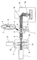
本発明の多層観察型リアルタイム共焦点顕微鏡の好ましい実施例は、図1に示すとおりである。図1の光学系において、1はレーザー光源、2は二重回転円板式高速共焦点スキャナー、3はインテンシファイド高速CCDカメラ、4は高速共焦点スキャナー2のピンホールを出たレーザー光をコリメート、すなわち視準化する凸レンズ、5は収束レンズ、6は収束レンズ5から出て反転像化したレーザー光を視準化する第2の凸レンズであり、このレンズ5,6間に本発明の多層観察ユニット7を構成する位相変更手段としての光学位相板の配列ディスクが配置される。レンズ6から出た視準レーザー光は蛍光位相差顕微鏡ユニット8に入射するようになっている。
A preferred embodiment of the multilayer observation type real-time confocal microscope of the present invention is as shown in FIG. In the optical system of FIG. 1, 1 is a laser light source, 2 is a double-rotating disk type high-speed confocal scanner, 3 is an intensified high-speed CCD camera, and 4 is a laser beam collimating the laser light emitted from the pinhole of the high-speed
高速共焦点スキャナー2は、レーザー光源1側にマイクロレンズアレーディスク9を、コリメートレンズ4側に多数のピンホールが渦巻き状に配置された所謂ニポウディスク10を同軸・対向的に設置したものであり (図5参照)、当然ながらディスク9のマイクロレンズアレーも、ピンホールアレーに対応した渦巻き状であり、両ディスク9,10の高速回転により、例えば、最速で1000フレーム/秒で光軸をx−y走査することができる。
The high-speed
両ディスク9,10間には励起用レーザー光を透過し、観察試料から返ってきた蛍光を反射するダイクロイックミラー11が配置され、その蛍光反射光路中には凸レンズ12が配置され、CCDカメラ3の受光面に結像するようになっている。CCDカメラ3は高速共焦点スキャナー2に対応して最速で1000フレーム/秒で光軸をx−y走査画像を撮影することができる。
A
本発明の多層観察ユニット7は、図1の光学系内においては駆動用モーター13と共に、側面でのみ示しているが、その具体的構成例としては、図の上方に取出して斜視図で示すように、光学特性の異なる複数の位相板セグメントa, b, c ・・・・をディスク状に配列したものである。光学特性がセグメントごとに段階的に異なる態様としては、各位相板セグメントの要素をなす等方性透明膜(当該斜視図においては区分図示していない)が同一膜物質から成る場合において、斜視図で拡大して示すように、その厚さを段階的に変化させるか、厚さは不変にして屈折率を段階的に変えるか、あるいはその両方の組み合わせを採用する。
The
多層観察ユニット7を通り、視準化レンズ6から出たレーザービームは、蛍光位相差顕微鏡ユニット8内の対物レンズ14に入射し、可変の深度において、ここでは模式的に示した通り、シャーレ等に収容された細胞・組織試料15内に焦点を結ぶようになっている。また、この場合は光学系構成の便宜上、顕微鏡ユニット8内には、対物レンズ14の前に平面ミラーからなる光路折り曲げ鏡16が配置される(図1参照)。
The laser beam that has passed through the
図2は、上述の光路折り曲げ鏡16を省略して、収束/視準化レンズ対5,6間に配置された多層観察ユニット7の位相板により、対物レンズ14により結ばれる焦点が効果的に深度調整される手順を示す模式図である。ここに(a)は、多層観察ユニット7の光路中セグメントの位相板要素が最も薄いものであるとき、(b),(c)は順次それより厚くなった場合であり、レンズ5,6間の基準中間結像面と各中間レベルを整合させて描いたものである。
In FIG. 2, the optical
図2(a)では、位相板要素が薄いため、収束レンズ5の周縁部から出て位相板要素7(a)内に入り、光軸と交差してから同要素7(a)を出るまでの距離が比較的短くなり (したがって光軸通過部との距離差も短くなり)、その部分と光軸出射部との位相差 (前者の位相遅れ)は比較的小さい。したがって、これらの光波が対物レンズ14により合焦するレベルは、試料15内の最上位Z1となる。
In FIG. 2A, since the phase plate element is thin, it exits from the peripheral edge of the converging
図2(b)では、位相板要素が(a)より少し厚いため、収束レンズ5の周縁部から出て位相板要素7(b)内に入り、光軸と交差してから同要素7(b)を出るまでの距離がやや長くなり (したがって光軸通過部との距離差もやや長くなり)、その部分と光軸出射部との位相差 (前者の位相遅れ)もやや長くなる。したがって、これらの光波が対物レンズ14により合焦するレベルは、試料15内の次のレベル(ここでは中間位)Z2となる。
In FIG. 2B, since the phase plate element is slightly thicker than (a), the phase plate element exits from the peripheral edge of the converging
図2(c)では、位相板要素が(b)より更に厚いため、収束レンズ5の周縁部から出て位相板要素7(c)内に入り、光軸と交差してから同要素7(c)を出るまでの距離が更に長くなり (したがって光軸通過部との距離差も更に長くなり)、その部分と光軸出射部との位相差 (前者の位相遅れ)も更に長くなる。したがって、これらの光波が対物レンズ14により合焦するレベルは、試料15内の更に次のレベル(ここでは最下位)Z3となる。
In FIG. 2C, since the phase plate element is thicker than (b), it exits from the peripheral edge of the converging
以上のことから、本発明の実施例においては、多層観察ユニット7の位相板要素がセグメントa、b,c,・・・と変位するごとに厚くなるため、対物レンズ14の対物面における光軸点から周縁部にかけて出射する波面の合焦点の深度は、効果的に十分な距離を変位することが理解できるであろう。また、この深度変位は、前述の実施例のごとく、多層観察ユニット7における各位相板セグメント要素(等方性透明膜)の厚さが段階的に変化する場合のほか、厚さは不変にして屈折率を段階的に変える場合、あるいはその両方の組み合わせを採用する場合にも生ずることは明らかである。
From the above, in the embodiment of the present invention, the phase plate element of the
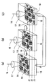
図3は、本発明の高速共焦点顕微鏡により観察深度を順次変更しながら、光学断層像を計測し、これらを合成する画像処理により、リアルタイム三次元像を得る手順原理を示す模式図である。図3(a)では、図2(a)の位相板セグメント要素により確立した焦点レベルZ1において観察試料を二次元走査し、図3(b)では、図2(b)の位相板セグメント要素により確立した焦点レベルZ2において観察試料を二次元走査し,更に図3(C)では、図2(C)の位相板セグメント要素により確立した焦点レベルZ3において観察試料を二次元走査したものである。 FIG. 3 is a schematic diagram showing a procedure principle of obtaining a real-time three-dimensional image by measuring an optical tomographic image while sequentially changing the observation depth with the high-speed confocal microscope of the present invention and synthesizing them. 3A, the observation sample is two-dimensionally scanned at the focus level Z1 established by the phase plate segment element of FIG. 2A. In FIG. 3B, the phase plate segment element of FIG. 2B is used. The observation sample is two-dimensionally scanned at the established focus level Z2, and in FIG. 3C, the observation sample is two-dimensionally scanned at the focus level Z3 established by the phase plate segment element of FIG. 2C.
各レベルにおいて描いた複数の線18は、図1に示した高速共焦点スキャナー2の二重板9、10におけるマイクロレンズ/ピンホールアレイの本数に応じて形成される走査線であり、19はその走査線上においてレーザービーム17が結ぶ焦点である。かくして、これらの合焦点レーザービームによりその試料点から励起・発光した蛍光のうち、往路のレーザービームと同様の経路を逆にたどる蛍光が、多層観察ユニット7により、同じく波面位相を調整され、高速共焦点スキャナー2のニポウディスク10における光軸位置のピンホールを通り、ダイクロイックミラー11によって反射され、凸レンズ12を通って高速CCDカメラ3により受光及び撮像処理されることは前述した通りである。
A plurality of
実施例において、図3(a)〜(c)の過程は、好ましくは1/30秒程度で行われ、高速CCDカメラ3で画像取得後三次元像として合成される。例えば、1秒間1000フレームの高速CCDカメラを用いて3層の三次元観察を行う場合、1秒間に1000/3=333.3の立体像が得られる。
In the embodiment, the process of FIGS. 3A to 3C is preferably performed in about 1/30 second, and is synthesized as a three-dimensional image after image acquisition by the high-
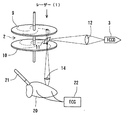
図4は、生体の左心室23及び左冠状動脈組織における心筋梗塞巣24の細胞を、本発明のリアルタイム共焦点顕微鏡によりリアルタイムで観察するため、カテーテル等、何らかの方法でレーザー励起した場合の模式図である。共焦点顕微鏡のレーザー光路先端(対物レンズ)25から出たレーザービーム17は前述の態様にしたがって多層的に二次元走査され、この領域24の細胞が三次元画像によりリアルタイムで観察され、例えば、壊疽を生じていること等が容易に発見できるようになる。なお、26は心房、27は大動脈である。
FIG. 4 is a schematic diagram in the case where cells of
また、標本ステージあるいは対物レンズを光軸方向に移動することによって左心室23全体も観察できる。標本ステージあるいは対物レンズの光軸方向の移動距離と多層観察ユニットによる焦点移動距離を規格化すると共に、同期化して観察することにより、図4のように広範囲な観察と局所的な詳細観察とを重ねて三次元観察することができる。
Further, the entire
標本ステージあるいは対物レンズの光軸方向の移動距離と多層観察ユニットによる焦点移動距離を規格化することにより、早い時間で被観察試料の光軸方向の深さを測定することもできる。移動距離を規格化する別な方法としては、すでに深さ方向の距離が測定済みの基準試料を事前に観察することにより、多層観察ユニットによる焦点移動距離を規格化することもできる。観察できる観察面と多層観察ユニットによる焦点移動距離の差を測定することにより、その異なる観察面の深さを測定できる。深さを測る場合には、多層観察ユニットとしてアナログ的に光軸方向の焦点移動距離を制御できる位相変更手段が好ましい。位相変更手段として印可電界によって制御できるポッケルス効果あるいはカー効果を持った電気光学結晶デバイスを用いることによりアナログ的に光軸方向の焦点移動距離を制御することができる。ポッケルス効果を有する材料としては例えばLiNbO3(ニオブ酸リチウム)結晶がある。カー効果を示す材料としては液体であるがCS2がある。本発明の顕微鏡は、三次元観察及び測長を早い時間で同時にできる。従って、実験用だけではなくマイクロデバイス等の生産段階での検査工程に最適である。 By normalizing the moving distance of the specimen stage or objective lens in the optical axis direction and the focal moving distance of the multilayer observation unit, the depth of the sample to be observed in the optical axis direction can be measured in an early time. As another method for normalizing the moving distance, the focal moving distance by the multilayer observation unit can be normalized by observing in advance a reference sample whose distance in the depth direction has already been measured. By measuring the difference between the observation plane that can be observed and the focal distance of the multilayer observation unit, the depths of the different observation planes can be measured. When measuring the depth, a phase changing means capable of controlling the focal distance in the optical axis direction in an analog manner as a multilayer observation unit is preferable. By using an electro-optic crystal device having a Pockels effect or a Kerr effect that can be controlled by an applied electric field as the phase changing means, the focal distance in the optical axis direction can be controlled in an analog manner. An example of a material having the Pockels effect is LiNbO3 (lithium niobate) crystal. A material that exhibits the Kerr effect is liquid but CS2. The microscope of the present invention can simultaneously perform three-dimensional observation and length measurement at an early time. Therefore, it is optimal not only for experiments but also for inspection processes in the production stage of micro devices and the like.
また、多層観察ユニットの収束/視準化レンズの倍率を変えることにより光軸方向の移動距離範囲を広くできる。被観察試料の大きさに応じて多層観察ユニットの収束/視準化レンズの倍率を変えることにより、被観察試料を1回の走査で三次元観察することができる。収束/視準化レンズの倍率を変える構造を設けたことにより、位相変更手段の少ない位相変化でも効果的に移動距離範囲を光学的移動距離範囲を広くできる。言い換えれば、多層観察ユニットを小型化することができる。この位相変更手段の小型化は位相変更の高速化を容易にする。 Further, the moving distance range in the optical axis direction can be widened by changing the magnification of the convergence / collimating lens of the multilayer observation unit. By changing the magnification of the converging / collimating lens of the multilayer observation unit according to the size of the sample to be observed, the sample to be observed can be observed three-dimensionally by one scan. By providing a structure for changing the magnification of the converging / collimating lens, it is possible to effectively widen the movement distance range and the optical movement distance range even if the phase change is small. In other words, the multilayer observation unit can be reduced in size. The downsizing of the phase changing means facilitates the speeding up of the phase change.
更に、高速に三次元観察ができるので、医学生物分野の試料及びエレクトロニクス分野の試料の三次元検査が可能になる。即ち、まず、光学的に三次元構造を有する被観察試料を作製する。例えば、医学生物分野の試料の作製は、蛍光材料を試料に混入することにより光学的に鮮明に観察できる被観察試料を準備する。半導体集積回路等のエレクトロニクス分野の試料作製において、製造されるシリコンウエハ表面は一般的にエッチング等で凹凸が形成される。凹凸の深さの絶対値を含めて正常かどうかを判断したいという、その被観察試料を標本ステージに設置する。本発明の光学顕微鏡の構成を用いて、その被観察試料の三次元デジタルデータを測定する。被観察試料が正常な三次元形状であるか否か判断するために、別途正常な三次元形状の試料を観察して得られたデジタルデータを検査判定基準デジタルデータとして設定しておく。測定された検査用の被観察試料の三次元デジタルデータと検査判定基準デジタルデータとを比較することにより、被観察試料が正常かどうかの判定をすることができる。繰り返し三次元デジタルデータを測定することにより、時間的に変化する動態の検査も可能になる。この動態検査の場合には、三次元データ走査を正確な時間で同期して評価することにより可能になる。動態の検査は、時間と共に変化する検査判定基準三次元デジタルデータを検査前に設定しておく必要がある。 Furthermore, since three-dimensional observation can be performed at high speed, three-dimensional inspection of samples in the medical and biological fields and samples in the electronics field becomes possible. That is, first, a sample to be observed having an optically three-dimensional structure is prepared. For example, in the preparation of a sample in the medical / biological field, an observation sample that can be observed optically clearly is prepared by mixing a fluorescent material into the sample. In the preparation of samples in the field of electronics such as semiconductor integrated circuits, the surface of a silicon wafer to be manufactured is generally uneven by etching or the like. The sample to be observed is placed on the specimen stage to determine whether or not it is normal including the absolute value of the unevenness depth. Using the configuration of the optical microscope of the present invention, three-dimensional digital data of the observed sample is measured. In order to determine whether or not the sample to be observed has a normal three-dimensional shape, digital data obtained by separately observing a sample having a normal three-dimensional shape is set as inspection determination reference digital data. By comparing the measured three-dimensional digital data of the sample to be observed with the inspection determination reference digital data, it can be determined whether or not the sample to be observed is normal. By repeatedly measuring three-dimensional digital data, it is possible to examine temporally changing dynamics. In the case of this dynamic examination, it becomes possible by evaluating the three-dimensional data scan synchronously with an accurate time. In the dynamic inspection, it is necessary to set inspection determination reference three-dimensional digital data that changes with time before the inspection.
従来のシリコンウエハの集積回路のパターン検査は、二次元的デジタルデータの判断が一般的であった。本発明の検査方法によれば、深さ方向のデジタルデータも含んだ三次元デジタルデータによる検査が可能になる。半導体集積回路においては、ますます表面構造が三次元化していくが、本発明の顕微鏡を用いて三次元検査を高速でできるようになる。医療分野においても、多くの試料を早く検査する必要がある健康診断のような用途に用いることが可能になる。 In the conventional pattern inspection of an integrated circuit on a silicon wafer, two-dimensional digital data is generally judged. According to the inspection method of the present invention, inspection by three-dimensional digital data including digital data in the depth direction can be performed. In semiconductor integrated circuits, the surface structure is increasingly three-dimensional, but three-dimensional inspection can be performed at high speed using the microscope of the present invention. Also in the medical field, it can be used for applications such as medical examinations where many samples need to be examined quickly.
以上述べたとおり、本発明の多層観察型リアルタイム光学顕微鏡、特に共焦点顕微鏡によれば、細胞や生体組織の三次元構造を、そのままの状態で高精度に観察することができる。すなわち、多層的に観察できない従来の方法では、本来三次元的な生体組織の営みを、シャーレ内での細胞培養等により二次元平面に置き換えることで可視化しているに過ぎず、生体の自然な姿を捉えているとは言いがたいものであったのに対し、本発明では、生体の営みを高速且つ立体的に可視化したものだからである。 As described above, according to the multilayer observation type real-time optical microscope of the present invention, in particular, the confocal microscope, the three-dimensional structure of cells and biological tissues can be observed with high accuracy as it is. In other words, in the conventional method that cannot be observed in multiple layers, the operation of a three-dimensional biological tissue is only visualized by replacing it with a two-dimensional plane by cell culture in a petri dish, and the natural living body This is because it is difficult to say that the figure is captured, but in the present invention, the operation of the living body is visualized at high speed and three-dimensionally.
上記のような本発明の技術的効果は、その観察結果から、これまでは見えなかった多くの情報をもたらすであろう。それはまた医学・生物学、並びに関連諸分野において、きわめて有用であるものと期待される。 The technical effects of the present invention as described above will bring a lot of information that has not been seen before from the observation results. It is also expected to be very useful in medicine / biology and related fields.
更に、本発明のリアルタイム光学顕微鏡の製作に当たっては、従来の光学顕微鏡の対物レンズ直前光路中に、前述した多層観察ユニットを挿入するだけでよいため、比較的低コストで実施可能であり、その産業上の利点もまた極めて大きいものがある。 Furthermore, in the production of the real-time optical microscope of the present invention, since the multilayer observation unit described above need only be inserted into the optical path immediately before the objective lens of the conventional optical microscope, it can be implemented at a relatively low cost. The above advantages are also quite significant.
1 レーザー光源
2 二重回転円板式高速共焦点スキャナー
3 高速CCDカメラ
4、6 視準化レンズ
5 収束レンズ
7 多層観察ユニット (位相変更手段)
8 蛍光位相差顕微鏡ユニット
9 マイクロレンズアレーディスク
10 ニポウディスク
11 ダイクロイックミラー
12 凸レンズ
13 駆動用モーター
14 対物レンズ
15 細胞・組織試料
16 光路折り曲げ鏡
17 レーザービーム
18 走査線
19 焦点
DESCRIPTION OF SYMBOLS 1 Laser
8 Fluorescence phase-
Claims (5)
前記光源からの照射光を被観察試料内に集光する対物レンズと、
前記光源から前記対物レンズに対し照射光線を入射させる光軸中に配置された収束/視準化レンズ対と、
前記収束/視準化レンズ対の間に配置され、透過光の位相を光軸横断面の所定範囲内で変化させることによって、前記対物レンズの観察面を段階的に深度調節するための位相変更手段と、
前記光源および前記収束/視準化レンズ対の間の光軸中に共焦点スキャナーと、を備え、
前記共焦点スキャナーは、
前記光源側に配置されたマイクロレンズアレーディスクと、
前記収束/視準化ディスク側に、前記マイクロレンズアレーディスクと同軸にこれに対向配置された複数のピンホールを有するニポウディスクと、
前記マイクロレンズアレーディスクおよび前記ニポウディスクの間に配置され、光源からの照射光を透過する一方、前記被観察試料から返ってきた蛍光を反射するダイクロイックミラーと、を備え、
前記位相変更手段が段階的に光学的特性の異なる複数の位相板セグメントを配列し、各セグメントが順次光軸を横切るように設置された回転板からなることを特徴とする多層観察型光学顕微鏡。 A light source;
An objective lens for condensing the irradiation light from the light source in the sample to be observed;
A converging / collimating lens pair disposed in an optical axis for making an irradiation beam incident on the objective lens from the light source;
Phase change for adjusting the depth of the observation surface of the objective lens stepwise by changing the phase of transmitted light within a predetermined range of the cross section of the optical axis, which is arranged between the converging / collimating lens pair Means,
A confocal scanner in the optical axis between the light source and the converging / collimating lens pair;
The confocal scanner is
A microlens array disk disposed on the light source side;
On the side of the converging / collimating disc, a Niipou disc having a plurality of pinholes arranged coaxially and opposed to the microlens array disc;
A dichroic mirror that is disposed between the microlens array disk and the nipou disk and transmits the irradiation light from the light source, and reflects the fluorescence returned from the sample to be observed .
A multilayer observation type optical microscope characterized in that the phase changing means comprises a rotating plate in which a plurality of phase plate segments having different optical characteristics are arranged step by step, and each segment is installed so as to sequentially cross the optical axis .
Priority Applications (4)
| Application Number | Priority Date | Filing Date | Title |
|---|---|---|---|
| JP2003337105A JP4239166B2 (en) | 2002-12-27 | 2003-09-29 | Multilayer observation type optical microscope and multilayer observation unit |
| US10/540,600 US7366394B2 (en) | 2002-12-27 | 2003-12-24 | Multilayer observation optical microscope and multilayer observation unit |
| AU2003296100A AU2003296100A1 (en) | 2002-12-27 | 2003-12-24 | Multilayer observation optical microscope and multilayer observation unit |
| PCT/JP2003/016641 WO2004061515A1 (en) | 2002-12-27 | 2003-12-24 | Multilayer observation optical microscope and multilayer observation unit |
Applications Claiming Priority (2)
| Application Number | Priority Date | Filing Date | Title |
|---|---|---|---|
| JP2002379869 | 2002-12-27 | ||
| JP2003337105A JP4239166B2 (en) | 2002-12-27 | 2003-09-29 | Multilayer observation type optical microscope and multilayer observation unit |
Publications (2)
| Publication Number | Publication Date |
|---|---|
| JP2004219987A JP2004219987A (en) | 2004-08-05 |
| JP4239166B2 true JP4239166B2 (en) | 2009-03-18 |
Family
ID=32716315
Family Applications (1)
| Application Number | Title | Priority Date | Filing Date |
|---|---|---|---|
| JP2003337105A Expired - Fee Related JP4239166B2 (en) | 2002-12-27 | 2003-09-29 | Multilayer observation type optical microscope and multilayer observation unit |
Country Status (4)
| Country | Link |
|---|---|
| US (1) | US7366394B2 (en) |
| JP (1) | JP4239166B2 (en) |
| AU (1) | AU2003296100A1 (en) |
| WO (1) | WO2004061515A1 (en) |
Families Citing this family (21)
| Publication number | Priority date | Publication date | Assignee | Title |
|---|---|---|---|---|
| JP4797425B2 (en) * | 2005-04-12 | 2011-10-19 | カシオ計算機株式会社 | Light source unit and projection device |
| US20070057211A1 (en) * | 2005-05-25 | 2007-03-15 | Karsten Bahlman | Multifocal imaging systems and method |
| DE102005036486A1 (en) * | 2005-07-20 | 2007-01-25 | Leica Microsystems (Schweiz) Ag | Optical device with increased depth of field |
| JP2007079278A (en) * | 2005-09-15 | 2007-03-29 | Univ Of Tokyo | Substance condition measuring device |
| US8081378B2 (en) * | 2005-10-13 | 2011-12-20 | Nikon Corporation | Microscope |
| US8537461B2 (en) * | 2007-11-26 | 2013-09-17 | Carl Zeiss Microimaging Gmbh | Method and configuration for the optical detection of an illuminated specimen |
| CN101903761B (en) * | 2007-12-19 | 2015-04-22 | 皇家飞利浦电子股份有限公司 | Detection system and method |
| JP5242304B2 (en) * | 2008-09-04 | 2013-07-24 | オリンパスメディカルシステムズ株式会社 | Observation system |
| JP5504881B2 (en) * | 2009-12-25 | 2014-05-28 | ソニー株式会社 | Arithmetic apparatus, arithmetic method, arithmetic program, and microscope |
| JP5056871B2 (en) * | 2010-03-02 | 2012-10-24 | 横河電機株式会社 | Confocal microscope system |
| JP5221614B2 (en) * | 2010-09-17 | 2013-06-26 | 独立行政法人科学技術振興機構 | Three-dimensional confocal observation device and observation focal plane displacement / correction unit |
| ITTO20110298A1 (en) * | 2011-04-01 | 2012-10-02 | St Microelectronics Srl | CONFOCAL OPTICAL DETECTOR, DETECTOR RING AND ITS MANUFACTURING PROCEDURE |
| US9104027B2 (en) * | 2012-04-27 | 2015-08-11 | Manufacturing Techniques, Inc. | Optical instrument for the simulation of atmospheric turbulence |
| US9696264B2 (en) * | 2013-04-03 | 2017-07-04 | Kla-Tencor Corporation | Apparatus and methods for determining defect depths in vertical stack memory |
| JP6318358B2 (en) * | 2013-04-08 | 2018-05-09 | 株式会社ニューフレアテクノロジー | Lighting device and inspection device |
| WO2015164844A1 (en) * | 2014-04-24 | 2015-10-29 | Vutara, Inc. | Super resolution microscopy |
| CN104101993B (en) * | 2014-07-10 | 2017-04-19 | 深圳职业技术学院 | Fourier microscope device and information sharing system and method |
| US10317597B2 (en) * | 2014-08-26 | 2019-06-11 | The Board Of Trustees Of The Leland Stanford Junior University | Light-field microscopy with phase masking |
| US10788403B2 (en) | 2015-03-11 | 2020-09-29 | Tissuevision, Inc. | Systems and methods for serial staining and imaging |
| US10495446B2 (en) * | 2015-06-29 | 2019-12-03 | Kla-Tencor Corporation | Methods and apparatus for measuring height on a semiconductor wafer |
| KR101900254B1 (en) * | 2017-04-25 | 2018-09-19 | 충북대학교 산학협력단 | Integral imaging microscope system using bifocal holographic optical element micro lens array |
Family Cites Families (6)
| Publication number | Priority date | Publication date | Assignee | Title |
|---|---|---|---|---|
| JPH08136810A (en) | 1994-11-08 | 1996-05-31 | Hamamatsu Photonics Kk | Confocal microscope |
| US5952562A (en) * | 1995-11-22 | 1999-09-14 | Olympus Optical Co., Ltd. | Scanning probe microscope incorporating an optical microscope |
| JP3917731B2 (en) | 1996-11-21 | 2007-05-23 | オリンパス株式会社 | Laser scanning microscope |
| JPH1138324A (en) | 1997-07-23 | 1999-02-12 | Nikon Corp | Laser scanning microscope |
| JP4481397B2 (en) * | 1999-09-07 | 2010-06-16 | オリンパス株式会社 | Optical apparatus and microscope |
| DE10105391B4 (en) | 2001-02-06 | 2004-11-25 | Leica Microsystems Heidelberg Gmbh | Scanning microscope and module for a scanning microscope |
-
2003
- 2003-09-29 JP JP2003337105A patent/JP4239166B2/en not_active Expired - Fee Related
- 2003-12-24 US US10/540,600 patent/US7366394B2/en not_active Expired - Fee Related
- 2003-12-24 AU AU2003296100A patent/AU2003296100A1/en not_active Abandoned
- 2003-12-24 WO PCT/JP2003/016641 patent/WO2004061515A1/en active Application Filing
Also Published As
| Publication number | Publication date |
|---|---|
| US20060147176A1 (en) | 2006-07-06 |
| JP2004219987A (en) | 2004-08-05 |
| US7366394B2 (en) | 2008-04-29 |
| AU2003296100A1 (en) | 2004-07-29 |
| WO2004061515A1 (en) | 2004-07-22 |
Similar Documents
| Publication | Publication Date | Title |
|---|---|---|
| JP4239166B2 (en) | Multilayer observation type optical microscope and multilayer observation unit | |
| US9885859B2 (en) | Structured illumination microscopy apparatus and method | |
| US11828710B2 (en) | Systems and methods for in-operating-theatre imaging of fresh tissue resected during surgery for pathology assessment | |
| JP5097247B2 (en) | Confocal microscope apparatus and observation method using confocal microscope apparatus | |
| EP2041613B1 (en) | Device and method for wide- field and high resolution imaging of tissue | |
| US9383568B2 (en) | Objective-coupled selective plane illumination microscopy | |
| JP5221614B2 (en) | Three-dimensional confocal observation device and observation focal plane displacement / correction unit | |
| WO2004036284A1 (en) | Cofocal microscope, fluorescence measuring method and polarized light measuring metod using cofocal microscope | |
| US10352819B2 (en) | Method of measuring transmission characteristics of optical transfer medium and image acquisition device using the same | |
| US20070091425A1 (en) | Microscope examination apparatus and microscope examination method | |
| CN110062603B (en) | Multiphoton endoscopic microscope for vertical cross-section imaging | |
| JP2005121796A (en) | Laser microscope | |
| CN115291381A (en) | Large-field-of-view high-resolution microscope and microscopic imaging method thereof | |
| NL2008873C2 (en) | Method and apparatus for multiple points of view three-dimensional microscopy. | |
| JP2006275964A (en) | Shading correction method for scanning fluorescence microscope | |
| JP2000126115A (en) | Optical scanning probe device | |
| EP1806575B1 (en) | Examination apparatus | |
| JP2006510932A (en) | Coherence microscope | |
| Rangrez et al. | Fluorescence in vivo endomicroscopy: High-resolution, 3-dimensional confocal laser endomicroscopy (Part 1) | |
| JP2002301018A (en) | Optical scanning probe device | |
| JP3144513B2 (en) | Fluorescence microscope | |
| CN115542527B (en) | Micro-nano robot positioning tracking method and device | |
| Krohne et al. | New method for confocal microscopy and its endoscopic application | |
| Lyman | 2022 Microscopy Today Innovation Awards | |
| JP2024500089A (en) | Confocal microscopy with photon reallocation |
Legal Events
| Date | Code | Title | Description |
|---|---|---|---|
| A621 | Written request for application examination |
Free format text: JAPANESE INTERMEDIATE CODE: A621 Effective date: 20050513 |
|
| A131 | Notification of reasons for refusal |
Free format text: JAPANESE INTERMEDIATE CODE: A131 Effective date: 20080618 |
|
| A521 | Written amendment |
Free format text: JAPANESE INTERMEDIATE CODE: A523 Effective date: 20080813 |
|
| RD02 | Notification of acceptance of power of attorney |
Free format text: JAPANESE INTERMEDIATE CODE: A7422 Effective date: 20080813 |
|
| A131 | Notification of reasons for refusal |
Free format text: JAPANESE INTERMEDIATE CODE: A131 Effective date: 20080903 |
|
| A521 | Written amendment |
Free format text: JAPANESE INTERMEDIATE CODE: A523 Effective date: 20081029 |
|
| TRDD | Decision of grant or rejection written | ||
| A01 | Written decision to grant a patent or to grant a registration (utility model) |
Free format text: JAPANESE INTERMEDIATE CODE: A01 Effective date: 20081125 |
|
| A01 | Written decision to grant a patent or to grant a registration (utility model) |
Free format text: JAPANESE INTERMEDIATE CODE: A01 |
|
| A61 | First payment of annual fees (during grant procedure) |
Free format text: JAPANESE INTERMEDIATE CODE: A61 Effective date: 20081211 |
|
| FPAY | Renewal fee payment (event date is renewal date of database) |
Free format text: PAYMENT UNTIL: 20120109 Year of fee payment: 3 |
|
| R150 | Certificate of patent or registration of utility model |
Free format text: JAPANESE INTERMEDIATE CODE: R150 |
|
| FPAY | Renewal fee payment (event date is renewal date of database) |
Free format text: PAYMENT UNTIL: 20120109 Year of fee payment: 3 |
|
| S111 | Request for change of ownership or part of ownership |
Free format text: JAPANESE INTERMEDIATE CODE: R313113 |
|
| FPAY | Renewal fee payment (event date is renewal date of database) |
Free format text: PAYMENT UNTIL: 20120109 Year of fee payment: 3 |
|
| R350 | Written notification of registration of transfer |
Free format text: JAPANESE INTERMEDIATE CODE: R350 |
|
| FPAY | Renewal fee payment (event date is renewal date of database) |
Free format text: PAYMENT UNTIL: 20130109 Year of fee payment: 4 |
|
| FPAY | Renewal fee payment (event date is renewal date of database) |
Free format text: PAYMENT UNTIL: 20140109 Year of fee payment: 5 |
|
| R250 | Receipt of annual fees |
Free format text: JAPANESE INTERMEDIATE CODE: R250 |
|
| R250 | Receipt of annual fees |
Free format text: JAPANESE INTERMEDIATE CODE: R250 |
|
| R250 | Receipt of annual fees |
Free format text: JAPANESE INTERMEDIATE CODE: R250 |
|
| LAPS | Cancellation because of no payment of annual fees |