JP4233121B2 - Recovery of fermented salts from dilute aqueous solutions. - Google Patents
Recovery of fermented salts from dilute aqueous solutions. Download PDFInfo
- Publication number
- JP4233121B2 JP4233121B2 JP50557499A JP50557499A JP4233121B2 JP 4233121 B2 JP4233121 B2 JP 4233121B2 JP 50557499 A JP50557499 A JP 50557499A JP 50557499 A JP50557499 A JP 50557499A JP 4233121 B2 JP4233121 B2 JP 4233121B2
- Authority
- JP
- Japan
- Prior art keywords
- water
- extractant
- amine
- mixture
- carboxylate
- Prior art date
- Legal status (The legal status is an assumption and is not a legal conclusion. Google has not performed a legal analysis and makes no representation as to the accuracy of the status listed.)
- Expired - Fee Related
Links
Images


Classifications
-
- B—PERFORMING OPERATIONS; TRANSPORTING
- B01—PHYSICAL OR CHEMICAL PROCESSES OR APPARATUS IN GENERAL
- B01D—SEPARATION
- B01D17/00—Separation of liquids, not provided for elsewhere, e.g. by thermal diffusion
- B01D17/02—Separation of non-miscible liquids
- B01D17/04—Breaking emulsions
- B01D17/042—Breaking emulsions by changing the temperature
-
- B—PERFORMING OPERATIONS; TRANSPORTING
- B01—PHYSICAL OR CHEMICAL PROCESSES OR APPARATUS IN GENERAL
- B01D—SEPARATION
- B01D11/00—Solvent extraction
- B01D11/04—Solvent extraction of solutions which are liquid
- B01D11/0446—Juxtaposition of mixers-settlers
- B01D11/0457—Juxtaposition of mixers-settlers comprising rotating mechanisms, e.g. mixers, mixing pumps
-
- B—PERFORMING OPERATIONS; TRANSPORTING
- B01—PHYSICAL OR CHEMICAL PROCESSES OR APPARATUS IN GENERAL
- B01D—SEPARATION
- B01D17/00—Separation of liquids, not provided for elsewhere, e.g. by thermal diffusion
-
- B—PERFORMING OPERATIONS; TRANSPORTING
- B01—PHYSICAL OR CHEMICAL PROCESSES OR APPARATUS IN GENERAL
- B01D—SEPARATION
- B01D17/00—Separation of liquids, not provided for elsewhere, e.g. by thermal diffusion
- B01D17/02—Separation of non-miscible liquids
- B01D17/0208—Separation of non-miscible liquids by sedimentation
- B01D17/0211—Separation of non-miscible liquids by sedimentation with baffles
-
- B—PERFORMING OPERATIONS; TRANSPORTING
- B01—PHYSICAL OR CHEMICAL PROCESSES OR APPARATUS IN GENERAL
- B01D—SEPARATION
- B01D17/00—Separation of liquids, not provided for elsewhere, e.g. by thermal diffusion
- B01D17/02—Separation of non-miscible liquids
- B01D17/0208—Separation of non-miscible liquids by sedimentation
- B01D17/0214—Separation of non-miscible liquids by sedimentation with removal of one of the phases
-
- B—PERFORMING OPERATIONS; TRANSPORTING
- B01—PHYSICAL OR CHEMICAL PROCESSES OR APPARATUS IN GENERAL
- B01D—SEPARATION
- B01D17/00—Separation of liquids, not provided for elsewhere, e.g. by thermal diffusion
- B01D17/02—Separation of non-miscible liquids
- B01D17/04—Breaking emulsions
- B01D17/041—Breaking emulsions with moving devices
-
- B—PERFORMING OPERATIONS; TRANSPORTING
- B01—PHYSICAL OR CHEMICAL PROCESSES OR APPARATUS IN GENERAL
- B01D—SEPARATION
- B01D17/00—Separation of liquids, not provided for elsewhere, e.g. by thermal diffusion
- B01D17/02—Separation of non-miscible liquids
- B01D17/04—Breaking emulsions
- B01D17/044—Breaking emulsions by changing the pressure
-
- B—PERFORMING OPERATIONS; TRANSPORTING
- B01—PHYSICAL OR CHEMICAL PROCESSES OR APPARATUS IN GENERAL
- B01D—SEPARATION
- B01D17/00—Separation of liquids, not provided for elsewhere, e.g. by thermal diffusion
- B01D17/02—Separation of non-miscible liquids
- B01D17/04—Breaking emulsions
- B01D17/045—Breaking emulsions with coalescers
-
- B—PERFORMING OPERATIONS; TRANSPORTING
- B01—PHYSICAL OR CHEMICAL PROCESSES OR APPARATUS IN GENERAL
- B01D—SEPARATION
- B01D17/00—Separation of liquids, not provided for elsewhere, e.g. by thermal diffusion
- B01D17/02—Separation of non-miscible liquids
- B01D17/04—Breaking emulsions
- B01D17/047—Breaking emulsions with separation aids
-
- B—PERFORMING OPERATIONS; TRANSPORTING
- B01—PHYSICAL OR CHEMICAL PROCESSES OR APPARATUS IN GENERAL
- B01D—SEPARATION
- B01D17/00—Separation of liquids, not provided for elsewhere, e.g. by thermal diffusion
- B01D17/02—Separation of non-miscible liquids
- B01D17/04—Breaking emulsions
- B01D17/048—Breaking emulsions by changing the state of aggregation
-
- C—CHEMISTRY; METALLURGY
- C07—ORGANIC CHEMISTRY
- C07C—ACYCLIC OR CARBOCYCLIC COMPOUNDS
- C07C51/00—Preparation of carboxylic acids or their salts, halides or anhydrides
- C07C51/42—Separation; Purification; Stabilisation; Use of additives
- C07C51/48—Separation; Purification; Stabilisation; Use of additives by liquid-liquid treatment
Description
発明の背景
発明の分野
この発明は,水性溶液から発酵塩類を単離するための新しいかつ新規な技術に関する。この発明の方法は、溶液から水を抽出して発酵塩類,殊に酢酸カルシウムのようなカルボン酸塩類を濃縮する。
関連技術の検討
多くの製造プロセスはカルボン酸を含む水性廃液またはプロセス流を生じる。これらは、酢酸セルロース、アスピリン、樟脳,及びRDX爆薬の製造,ならびにセミ−ケミカルパルプ化及び原料または溶剤として酢酸を用いるその他のプロセスが包含する。さらには、水性溶液から酢酸の回収を伴う酢酸のためのおおくの製造方法がある。例えば、酢酸を製造する主要な方法は、メタノールのカルボキシル化、ブタンのような炭化水素の液相酸化、及びアセトアルデヒドの酸化である。アルコール発酵及び木材の分解蒸留のような初期のプロセスは、希薄な水性溶液を生じた。より最近には、希薄水性溶液を生産する反芻胃微生物を用いてバイオマスから酢酸またはその他のカルボン酸を製造するための方法が提案されてきている。これらのプロセスにおける酸の濃度は、高い酸濃度は微生物生育を阻害するので、必然的に、希薄でなければならない。
水性溶液から酢酸を回収するためにいくつかの方法が、開発されてきている。これらの方法は液体−液体溶媒抽出、共沸蒸留、及び抽出蒸留を包含する。単純蒸留は、(1)水と酢酸との間の相対的揮発性が1に近く、希薄水性酢酸溶液のためには最悪となり、そして(2)水は酢酸と比較してより揮発し易い成分であり、このことは、全てのみずが希薄酢酸溶液から気化されなければならず、回収される酢酸の単位当たりの大きなエネルギーコストを招くことを意味する、ので適当ではない。6−7%の酢酸を含む木材乾留酸から酢酸を回収するために、抽出蒸留は多年にわたりスイダ(Suida)法において使用された。再循環木材油んが抽出剤として使用された。酢酸合成プラントにおいて、共沸蒸留がより高い濃度の流れのために使用された。酢酸メチル及び酢酸エチル、ジイソプロピルエーテル、及びベンゼンは、一般的に共沸蒸留のために使用される同伴剤であるが、その他のエステル類、エーテル類、ケトン類、塩素化炭化水素類、及びアルコール類も使用されている。
酢酸製造の特定応用において、その他の方法が使用され得る。例えば、凍結濃厚化は、ビネガー濃厚化のために小規模プロセスとして長年使用されてきた。炭素またはアニオン交換剤での吸着及び化学誘導化、それに続く、化学誘導体の分離及び再生も利用できる。慣用的な誘導体化法は、木材乾留酸からの酢酸回収のための酢酸カルシウム法である。
酢酸カルシウム誘導法において、水酸化カルシウムが酸と反応して酢酸カルシウムを作り、これが気化により濃厚化される。次いで硫酸のような、強酸を加えて遊離の酸を放出させる。この方策は石灰、及び硫酸のような薬剤を消費して、廃水性塩副生物として石膏を生じる。
水からのカルボン酸の回収は、溶剤抽出の最も古い応用である。カルボン酸の溶剤抽出は1世紀前に提案された。並流抽出、蒸留によるラフィネート相からの残留溶剤の回収、及び回収酸からの同時抽出水を除去するための共沸蒸留の使用のような、より精巧な抽出技術の発展に伴い、水性溶液からのカルボン酸の溶剤抽出が酢酸カルシウム誘導体化法に取って代わっている。
一般に、水性溶液からの抽出は今まで、共沸蒸留が好ましい約80%(w/w)以上の酢酸濃度の供給物(水性溶液)を除き、酢酸を回収するための最も好ましい方策であった。新しい抽出剤、抽出方法の開発、及び経済構造の変化に基づき、今や、抽出は30%(w/w)以下の酢酸を含む供給原料のために好適であり;抽出蒸留は30−80%(w/w)の範囲の供給原料のために好ましく;そして共沸蒸留及び単純分別(蒸留)はより濃厚な供給原料のためにてきとうである。
文献において、溶剤抽出は、希薄水溶液からカルボン酸を回収するためのメインテーマであった。溶剤が部分的に水溶性である傾向が有るので、ラフィネートから残留溶剤を除去または回収するために一単位操作が必要とされる。典型的な抽出プロセスは、三単位操作、抽出器、溶剤再生器、及び遊離酸回収プロセス、を用いてカルボン酸を回収する。慣用的抽出プロセスでは、まず酸を有機相中へ抽出し、次いで酸を水性相へ逆抽出し、かくして有機相を再生する。再生プロセスにおいて、抽出物から酸を逆抽出するのに使用される水性相は、普通は、容易に気化され得る低沸点アルカリ性溶剤(例:トリメチルアミン)を含む水性溶液である。このプロセスを用いて、カルボン酸は、分離及び回収され得る。
カルボン酸を回収するために使用される抽出剤の中でも、水及びカルボン酸に関してより大きな溶媒容量及び選択性を得るために使用できる反応性、塩基性抽出剤(例:第3アミンまたはホスフィンオキシド類)である。溶剤抽出は、カルボン酸回収のために潜在的に魅力のあるプロセスであるが、それは、普通、これらの酸が水に対して大きな親和性を有することによって躊躇される。従前の研究者は、水性溶液からカルボン酸を抽出ために比較的高い平衡分配係数をあたえる幾つかの抽出剤を特徴付けた。高い平衡分配係数は、より低い溶剤:原料流量の使用を可能とする。
第1アミンは、水性溶液と共に使用されるには余りに水に溶解性であり過ぎる。第2アミンは、蒸留による再生の際に、アミドを形成し易い。従って、長鎖第3アミンが、希薄水性溶液からカルボン酸を回収するための最も好まれる抽出剤となってきた。適切な希釈剤及び温度もしくはpHの揚動(スイング)のしようにより、第3アミンは、カルボン酸回収のためのより強力な抽出剤となってきた。
脱塩
溶剤抽出は、海水または半海水から飲料水を回収するための方法としても提案されてきた。アミン溶剤での海水抽出は、濃縮塩水(ラッフィネート)及び水とアミンを含む抽出物を生じた。清澄水は、水中での溶剤の溶解度が大きく低減する高い温度まで、その水担持抽出物を加熱することにより回収された。従来の水の溶剤抽出に関する検討は、Davison等(Davison et al“Structure and Amine−Water Solubility in Desalination by Solvent Extraction”,J.Chem.Eng.Data 1960,5,420−423;Davison et a1“Thermodynamics Cycles For Recovery of Water by Solvent Extraction”I&EC Process Design and Development,1964,3,399−404;Davison et al“Phase Equiibria of Desalination Solvents;Water−NaCl−Amines”J.Chem.Eng.Data,1966,2,304−309;Davison et al“A Solvent Extraction Desalination Pilot Plant”,Desalination,1967,3,17−26;Davison及びHood米国特許3,088,909;Davison及びHood米国特許3,424,675参照)。
バイオマスからのカルボン酸
バイオマスから有機酸を製造するのに嫌気性細菌を使用することに関心が増している。カルボン酸の希薄水性流は、リグノセルロースバイオマスを発酵することによって製造できる。発酵ブロス中の濃度は、アセトジェニック発酵細菌への酸の自家毒性によって制限される。それは6%(w/w)ほども高いことがあるが、2−4%がより典型的である。生成物阻害は酸を連続的に除去することによって低減できる。
抽出発酵は、その場で(in situ)阻害酸を取り出し、バイオリアクターの生産性を向上させることが提案されてきている。しかし、微生物が生育するpH(約6.8)においては、わずかに1%が未解離酸であり;残部は抽出されない、殊に第3アミンによって抽出されない塩である。殆どの抽出剤は、酸性pHでのみ効果的に働き、けれどもアシドジェニック嫌気微生物は、pH6以下で劣悪な生育速度を有する。従って、抽出発酵は、酸生成物を、その場で、取り出すのには実行できない。
さらには、低分子量第3アミンを用いて水性発酵ブロスからカルボン酸を溶剤抽出した後、酸−アミン錯体を壊して、共沸蒸留または逆滴定により遊離酸を回収し、アミン抽出剤を再循環させなければならない。希薄水性溶液からカルボン酸を回収するためには、抽出−再生プロセスは、pH調整のための酸添加及び主抽出剤を再生するための追加の溶剤−抽出プロセスを必要とする。さらには、第3アミン抽出剤(またはホスフィンオキシド抽出剤)は、必然的に高分子量を有して、それが水に非混和性であるようにしなければならない。しかし、これらの抽出剤アミンを完全に水に非混和性とすることは不可能であるので、若干の抽出剤は水性相に必ず存在する。それらの高分子量の故に、これらの抽出剤は、非揮発性であり、蒸留塔でのストリッピングによっては回収できない。従って、追加の抽出剤が、損失したものの代わりに添加されなければならず、従って追加の経費が生じる。
必然的に、発酵で生産される時に、酸生成物は主としてカルボン酸塩として存在する。カルボン酸の水性溶液のpHは、その酸が解離してヒドロニウムイオンを水溶液中に放出するので、通常は低い。活力ある発酵を保持するには、ヒドロニウムイオンと反応して、微生物活性が最大となる中性に近いpHを維持する中和剤(すなわち、石灰または石灰石)を添加する必要がある。中性近くで、生成物のわずかに1%がカルボン酸であり;残部はカルボン酸塩として存在する。従って伝統的なカルボン酸回収技術は、簡単には応用できず、別の技術を開発する必要がある。
発明の概要
慣用的溶剤抽出での発酵ブロスからのカルボン酸の回収は、経済的でなく、特に理想的抽出剤(すなわち、カルボン酸塩を有機相中へ抽出できるもの)が現在利用できないときに経済的でない。従って、本発明者は水から酸を除く慣用的な方策ではなく、カルボン酸塩(典型的にはカルシウム塩)の希薄水性溶液から水を除去することによって発酵ブロスを濃厚化する新しい方法を開発した。この新規な抽出は、水性相から水を除去するが、塩を選択的に水性相に保持する。水は有機相中へ抽出されるので、塩は水性相中で濃厚化される。その水は、水を有機相から追い出す温度上昇によって有機相から回収され得る。この回収水は残留有機物質をストリッピングした後に発酵へ返還されうる。この発明の方法において、残留有機物も濃厚化された生成物からストリッピング除去されうる。
本発明は、発酵を介して作られた希薄水性カルボン酸塩溶液(2−5%)を濃厚化することに関する。殊に、この発明は発酵により(すなわち、反芻胃微生物により、混合酸発酵により、または純粋培養発酵により)作られたカルボン酸塩が水性溶液から回収され、そして抽出剤が都合よくまた経済的に抽出プロセスへ再循環される、カルボン酸の製造に属する。カルボン酸塩はモノカルボン酸塩である必要がなく、例えばヒドロキシル基のような他の官能基を含んでいてよい。カルボン酸塩は飽和炭化水素の誘導体である必要がなく、不飽和を含んでいてもよい。発酵で生産することが出来、本発明で回収出来る典型的カルボン酸塩は、酢酸塩、プロピオン酸塩、乳酸塩、スクシン酸塩等を包含する。
【図面の簡単な説明】
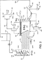
図1は、発酵塩を濃厚化するためのプロセス(方法A)の概略図を示す。
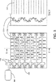
図2は、定期的クリーニングを採用するミキサー/デカンターの概略図を示す。
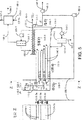
図3は、アミン及び水の均一穏和混合を達成するための方法の概略図を示す。
図4は、アミン及び水を沈静化するのに使用される平衡板の二つの可能な形態を示す。
図5は、連続式クリーニングを採用するミキサー/デカンターの概略図を示す。
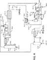
図6は、プロセスエネルギー値に影響を与える装置を示す方法Aの単純化概略図を示す。
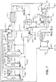
図7は、プロセスエネルギー値に影響を与える装置を示す方法Bの単純化概略図を示す。
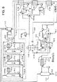
図8は、プロセスエネルギー値に影響を与える装置を示す方法Cの単純化概略図を示す。
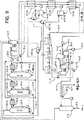
図9は、改変態様方法Cの単純化概略図を示す。
図10は、改変態様方法Bの単純化概略図を示す。
発明の詳細な説明
この発明は、その好ましい具体化において、希薄カルボン酸塩を含む発酵ブロスを水に対して高い親和性を有し、カルボン酸塩に対して低い親和性を示す低分子量第2または第3アミンに接触させる方法である。脱塩に関する従前の研究(Davison等,Phase Equilibria of Desalination Solvents;Water−NaCl−Amine. J.Chem.Eng.Data.1966,2,304−309)から、二つの低分子量アミン、すなわち、トリエチルアミン(TEA)及びN,N−ヂエチルメラミン(DEMA)を選択した。その理由はそれらの適切な温度範囲において水性塩溶液から水を選択的に抽出するための優れた能力のためである。水含有アミンの温度は、水をアミンから、及び他の相から分離させる約20−30℃だけ上昇させた。カルボン酸塩は発酵ブロス内に留まり、濃厚化された。水性相中の残留アミンは、アルカリ(例:石灰)を添加してpHを上昇させ、それによりアミンを揮発性となすことにより、回収した。次いで残留アミンは蒸留カラム内でそれらをストリッピング除去して回収した。
過去においては、塩溶液からの水の抽出は、塩水、例えば海水、半塩水、等、から飲料水を回収するのに応用された。本発明は、下記のように、この従前の応用と区別される:
1. 発酵においては、カルボン酸塩に係わるカチオンを選択することができる。2価イオン(すなわち、カルシウム)は1価イオン(すなわち、ナトリウム、アンモニウム)よりも十分にアミン抽出剤から排除される。従って、2価カチオンを選定することにより、水は塩溶液からより選択的に除去されうる。対照的に、海水またま半塩水中のカチオンは、自然によって規定され、典型的には1価カチオンである。結果として、水と塩は効率的に分離されない。
2. 本発明において、塩は所望の製品であるが、従前のプロセスにおいては、水が所望の製品である。カルボン酸塩は、水よりもはるかに望ましく、価値があり、本発明に好ましい経済性を与える。対照的に、水のアミン抽出は、経済的に魅力的でない。
3. 飲料水プロセスにおいて、水製品は人の消費用に受け容れられるために実質的に塩を含んではならない。これは、ストリッピング部に加えて、大型の精留部の使用を必要とする。これらの追加の精留段階は追加の経費を生じさせる。対照的に、本発明は水は単に発酵槽へ再循環されるだけなので、その水の中により高い塩濃度が許容され得る。従って、精留部はより少ない段階を有することができ、あるいは全く除くことができる。
4. 全ての水性流からの完全なアミン回収は良好な経済性のために実施される;他方、損失アミンの補充経費は余りにも大きい。アミンは、蒸留カラム内でそれを水性流からストリッピングすることにより回収される。アミンが非揮発性アミン塩ではなく、揮発性遊離アミンとして存在することを確保するために、アルカリを加えてpHを上昇させる必要がある。われわれの発明において、水性流に石灰を添加することにより容易に達成できる。中和剤はいずれにしても発酵器に添加されなければならないので、これに関連しての経費は殆ど無い。従って、アミンを発酵器と組み合わせる事に関して相乗性及び効率性がある。対照的に、飲料水プロセスにアルカリを添加することは、アルカリに関してのみならず、その回収に関しても著しい経費がかかり;飲料水中にアルカリを残すことは、許容されえない。飲料水からのアミンの完全除去は、その潜在的な健康への影響のために必須である。
発酵によって製造することができ、本発明の方法によって濃厚化できるカルボン酸塩は、酢酸、乳酸、スクシン酸、等の塩を包含する。本方法は、発酵以外の方法で作られた希薄カルボン酸水性溶液にも応用できる。
本発明によれば、有機相は、第2または第3アミンを含む。好ましいアミンは、低分子量アルキル第2または第3アミン、またはそれらの混合物を包含する。好ましいアミンは、式R3Nのアミンであり、Rはメチル、エチル、n−プロピル、またはイソプロピルである。最も好ましいアミンは、トリエチルアミン、N,N−ジエチルメチルアミン及びこれら二つのアミンの混合物である。二つのアミンの種々な比の使用は、異なる下限臨界温度を有する抽出システムを与える。適切なアミン組成を選択することにより、抽出プロセスを10℃から70℃の任意の提案温度で操作することができる。この温度範囲内には、適切な発酵システムを開発する際に柔軟性を与える中等温度好性及び高温度好性酸生産性細菌がある。リグノセルロースバイオマスを使用する最も好ましいカルボン酸生産微生物は、:(i)ウシ反芻胃または嫌気性下水消化槽から得られる中等温度好性(40℃)混合培養物,及び(ii)嫌気性下水消化槽から得られる高温度好性(55℃)混合培養物;である。他の期待できる高温度好性菌は、酢酸とエタノールを一般に等量で生産するセルロース分解性微生物クロストリジウム・サーモセルム(Clostridium thermocellum)である。適当な発酵プロセスは、本件と同時に出願された1997年6月30日付けの“Method for Conversion of Biomass to Chemicals and Fuels”の名称の米国出願シリアルNo.08/885,896により詳細に記載されており、参照のためここに導入される。
発酵ブロスの不必要な加熱または冷却を避けるために、抽出は、発酵温度でまたはその近くで、例えばその微生物に応じて40℃または55℃で、あるいはその近くで、操作される。
水性相が低分子量アミンと接触するときに、pHが上昇して水酸化カルシウムを形成する。水酸化カルシウムはかなり不水溶性であるので、若干沈殿し溶液からカルシウムイオンを取り除く。これらのイオンは、アミンイオンで置き換えられて水性相中にアミン−カルボン酸錯体を形成する。水溶性カルボン酸アミンの形成は、ストリッピング器へ水酸化カルシウムを添加し、アミンが揮発するときにカルシウムがアミンに置き換わるようにすることにより、行われる。
典型的には、リグノセルロースバイオマスは、発酵されて、低混和性有機抽出剤で水を抽出され得るカルボン酸塩希薄溶液を生じる。好ましいこれらの有機抽出剤は、低分子量第2または第3アミン、例えばトリエチルアミン(TEA)、ジイソプロピルアミン(DIA)、及びN,N−ジエチルメチルアミン(DEMA)である。典型的な発酵温度に相当する40℃−50℃で、これらの低分子量第3アミンまたはそれらの混合物は、カルボン酸塩を含む希薄水性溶液から多量の水を抽出できる。従って、希薄カルボン酸塩溶液は、選択的に水を除去することによって濃厚化されうる。より低い温度において、アミン相は20−35%の水及び無視し得るカルボン酸塩を含む。温度が上昇されると、水はアミンから相分離し、アミンが再循環され、さらに水を抽出するのに再使用できるようになる。典型的な例において、この方策を用いて、約82.5%の水を慣用的な多段階並流抽出で3%希薄溶液から除き、かくして15%の濃厚化カルボン酸塩溶液を与えることができた。
この発明の典型的具体例は、図1を参照して説明できる。発酵ブロス5は、固体分離機7(例:フィルター、ハイドロクロン、遠心分離、沈降器)で濾過されて、不溶解性残渣8(例:細胞、未反応バイオマス)を除去される。固体を含まない溶液9は、ミキサー10へ送られ、ここで石灰12が添加されて、pHを約11.5まで高める。この高pHは、無機質及び有機物(例:タンパク質、炭水化物ポリマー等)を沈殿させる。スラリー15は、固体分離機20(例:フィルター、ハイドロクロン、遠心分離、沈降器)へ送られ、ここで沈殿物25がポンプ27で除去される。図1は、沈殿物が発酵槽へ返還されることを示している。あるいは、それはさらに処理されて、無機質、タンパク質及び炭水化物ポリマーを、それらの成分の価値に応じて分離することもできる。
ポンプ32を用いて、沈殿不含有液体30は、一連のミキサー/デカンター40へ送られ、ここでそれは貧水(water−lean)アミン34と向流関係で接触する。(図1は一連のミキサー/デカンターがアミン及び水相を向流接触するのに使用されるように示しているが、充填カラム、回転ディスクカラム、オッシレイティングプレートカラム等のようなその他の接触装置を使用できる。適切な接触器の選定は、規模に左右され;ミキサー/デカンターは大きな流量のために好ましい。図1は5つのミキサー/デカンターを示しているが、より少ないまたはより多いものを使用できる。)沈殿不含有液体30は、ミキサー/デカンター40eへ送られ、ここでそれはミキサー/デカンター40dからのアミンと混合される。アミンは水相から幾分かの水を吸収し、かくして水相の塩濃度を上昇させる。図2に示されるように、アミン/水混合物は、ミキサー/デカンター中の一連の平行板140を介して流れ、集積部145に入り、ここでアミン相及び水相が分離する。低い密度を有するアミン相は頂部から回収され、水相は底から回収される。溜150はアミン/水混合物の高さを調節するようにセットされている。アミンは頂部を越えて流れ、水は下方流として回収される。
図1に示した具体例において、水に富むアミン相65は分離機55へ送られて、吸収水を回収する。水相69は、ミキサー/デカンター40dへ送られ、ここでそれは、ミキサー/デカンター40cからのアミンと混合され、そのアミンはさらに水を吸収して水相をさらに濃厚化する。このプロセスは、他のミキサー/デカンターにおいてくりかえされる。水相が右から左へ移動するにつれて、その塩濃度が増大する。アミン相が左から右へ移動するにつれて、その水含量が増大する。各ミキサー/デカンターにおいて、水とアミンが混合される。貧水アミン34が水61と混合されるときに殊に大きな混合熱が放出されるので、ミキサー/デカンター40aについての混合は、冷却器50を備えた別個の容器で実施される。その他の各ミキサー/デカンター(40bから40e)も混合熱があるが、それははるかに小さく、それは温度を調節する熱交換器45によって除かれる。水ポンプ46は、水を熱交換器内を流動させ、そして隣接のミキサー/デカンター40へ向ける。ポンプは、水の流動のためだけに必要とされる;ミキサー/デカンター40を連続的に低下する水準に配列することにより、アミンはアミンポンプの必要なく重力によって流れるようになろう。
最高の塩濃度を有する水流51は、除去されなければならない溶存アミンを含んでいる。それは向流熱交換器58で予熱され、ストリッピング器53へ送られここでスチーム59がアミンを気化させる。アミンが、非揮発性のイオン化種ではなく、揮発性の非イオン化種として存在することを確保するために、石灰54を添加して、pHを上昇させる。揮発性アミンは、スチームをも含む流れ60で退出する。流れ60は、分離機55へ送られ、ここでそれは水とアミンとを分離するのに必要とされる潜熱のいくぶんかを与える。アミン不含有の濃厚化製品62は、更なる下流での処理に直ぐに使用できる。
ポンプ66は、富水アミン65を向流熱交換器67へ送り、ここで温度が上昇される。熱交換器67においては、温度が上昇するにつれて、みずがアミンから相分離し始める。このプロセスは、分離機55で完結され、ここでは、スチーム77の形の、追加の熱が温度上昇のために供給され、アミンから水を分離するのに必要な潜熱を供給する。分離機55は、機械的ミキサーを要しないことを除きミキサー/デカンター40と類似のデザインである。
分離機55から出る水相68は、溶存アミンを含んでいる。それは向流熱交換器70で予熱され、ストリッピング器75へ送られここでスチーム74がアミンを気化させる。アミンが、非揮発性のイオン化種ではなく、揮発性の非イオン化種として存在することを確保するために、石灰76を添加して、pHを上昇させる。揮発性アミンは、スチームをも含む流れ78で退出する。流れ78は、分離機55へ送られ、ここでそれは水とアミンとを分離するのに必要とされる潜熱のいくぶんかを与える。非常に低い塩含量のアミン不含有水79は、向流熱交換器70及び向流熱交換器67で冷却され、発酵槽へ返還される。もしも過剰の水がパージされなければならないときには、流れ79から側流を取り出し、最終排出のための廃水処理プラントへ送ることができる。分離機55から出る貧水アミン34は、向流熱交換器67内を圧送され、ミキサー52で水と混合する。
混合及びデカンテーションは通常別個の装置部分で行われる。混合は、典型的には、攪拌タンク、ポンプ、またはインラインスタチックミキサーで実施される。デカンテーションは、静置タンクまたは平行板分離機で実施することができる。平行板分離機は、ハーゼンによって1904年に初めて記載された。
好ましい態様において、本発明は、ラフィネート及び抽出相を一緒に混合し、ついでそれらをデカンテーションして、分離する装置を提供する。水平管内でデカンテーションが迅速に起こることが判明した。この発見を実地利用するために、本発明は、図IIに示す装置を提供する。この具体例の独特な特徴の中でも、それがミキサー及びデカンター両者を結合して単一装置となることが挙げられる。図2は、ミキサーデカンター40の詳細な側面図を示す。それは4つの主要部:混合部130、沈降部135、集積部145、及び溜部150に分けられる。
混合部130において、翼115を用いて水110及びアミン120が均一に混合される。平衡は迅速かつ容易に達成されるので、混合は非常に穏やかでよい。従って、エマルジョンは形成されず、アミン相は水相から迅速にデカントする。アミン流量は水流量の約5または6倍大きいが、水が連続相で、アミンが不連続相である。このタイプの操作は、アミンの滞留時間を極めて短くすることを可能とし、これはアミンの在庫を削減し、コストを低減する。図2は、混合を行う翼を示す。図3は、ベアリング240で所定の位置に保持されている軸220に装着された一連の「指」230を使用するべつの態様を示す。軸は、ギヤー210を回転させるモーター200によって駆動される。隣接する軸は逆方向に回転する。相隣れる軸の指は混合部130で均一な混合が起こるように散在されている。混合の程度は、回転速度と軸当たりの指の数によって決定される。均一混合を促進するために水及びアミンは混合部130の多数の位置で導入しうる。
図2に示されるように、沈降部135は、一連の平行板を備えている。混合部130からの分散相を迅速に合体させるように短い沈降距離を有する。沈降部135におけるアミンの短い滞留時間は、資本コストを低減するアミン在庫削減をなす。図4は、平行板の二つの可能な具体例を示す。図4A及び4bの両方は、波型板、建物のサイディングによく似たもの、を使用する。この二つの態様は、平行板140の配向においてのみ変わっている。図4aにおいては、一枚置きの板が同じ配向であるが、図4bでは、それぞれの板が同じ配向である。図4aに示された板の配向は、たとえ深い波形があっても、非常に近接した板間隔を可能とするので好ましい。近接した板間隔は、流れが乱流ではなく線形であることを確保し、こらは合体を促進する。アミン/水相が平行板間を流れるときに、各相が合体する;アミン相(低密度である)は最も高い所へ浮上し、水相(高密度である)は最も低い所へ沈む。
図2は、集積部145が単に静置タンクであることを示す。
集積部145は、連続相としての水と分散相としてのアミンとで運転される。合体アミンが沈降部135を去るときに、それは迅速に上方へ浮上する。アミンが上方へ流動するときに、隣接アミンによる妨害を低減するために、平行板140は沈降部135において低いほど順順に長くなっている。沈殿水酸化カルシウムのような固体は、積集部で沈降し、ポンプ190によって除去され、固体分離機191(例:フィルター、ハイドロクロン、遠心分離機)へ送られる。固体は、ストリッピング器75または53へ返還され、アミンを気化させるのにひつような石灰を与える。
図2は、溜部が溢流溜132及び下方流溜131からなることを示す。溢流溜132は、アミンの上面の高さを設定し、下方流溜131は、アミン/水界面の高さを設定する。アミン相は、溢流溜132を越えて流れ、水相は下方流溜131を越えて流れる。アミン滞留時間を短縮し(かくしてアミン在庫を低減する)ため、下方流溜め131は、上方のアミン層の厚さが最小化されるように抽出される。
「屑層」がアミン/水界面に集まりことがあるので、ポンプ180を備えてアミン/水界面から流体を引き出し、それを固体分離機183(例:フィルター、ハイドロクロン、遠心分離機)へ導く。アミン182は、集積部145へ返還される。スチーム188を用いて、その分離された固体183を室189内でストリッピングしてアミンを取り出すことができる。排出蒸気187は、分離機55へ送られ、アミンから水を分離するために必要なエネルギーを与える。スチームストリッピング処理固体184の性質によって、それらは発酵槽へ返還でき、またはそれらは適切な方式で処分できる。
平行板140を介しての流れは低いので、固体(例えば、沈殿水酸化カルシウム)は、終局的には沈降部135を詰まらせることがある。平行板140を清浄化するために、アミン流120が停止させられ得る。弁126は、開かれて上位貯蔵タンク125からの水が重力によって平行板内を急速に流れて、平行板内に沈降された固体を同伴する乱流を生じさせるようにできる。同伴固体194は、集積部145またはサージタンク195に集められる。清浄化操作の実施後、アミン流動が再開され、ミキサー/デカンター40が以前のように継続する。ミキサー/デカンター40の正常操作中に、ポンプ185は水をゆっくりと、次の清浄化操作に備えている上位タンク125へ返す。
図2において、平行板140を清浄化するのに用いられるタンク125及び195は、固体を同伴するために必要とされる乱流を引き起こすために大きくなくてはならない。図5は、平行板140−5が連続的に清浄化され、清浄化装置が有利にかなり小型化できる、別の態様を示す。ルーバー320−5は開き、または閉じることができる。閉じたとき、平行板140−5の部分は分離され、残りの平行板がそれらの通常の機能を発揮している間に、清浄化されうる。図5に示されるように、ルーバー320−5a及びルーバー320−5cは開いて、平行板140−5の上方及び下方部分を通常に機能させ;しかるにルーバー320−5bガ開いて、平行板140−5の中間部を清浄化されうるようにする。視点Zに示されるように、弁310−5bは開かれ、その他の弁310−5a及び310−5は閉じられている。この弁配置は、ポンプ185−5から得られる高速水が中間部の平行板140−5中の固体を同伴して、その固体を集積部145−5へ排出できるようにする。そこで固体は沈降し、ポンプ190−5によって捕集される。
他の技術と比較して、図2−5に示されたミキサー/デカンターは、多数の利点を与える。分離しているミキサー及びデカンターと比較して、必要とされる配管が少ない。混合の程度は、掻き混ぜ速度によって調整され、ミキサーとしてのポンプの使用と異なり、極めて穏やかな混合が達成される。さらには、混合の程度は、アミン及び水の添加速度と無関係であり、インラインスタチックミキサーよりも制御が良好にできる。平行板140の間に流れを導入することにより、静置タンクと比べて、相がはるかに迅速に分離する。水/アミンの完全分離を促進するために、水滞留時間を、集積部145の容積を大きくすることにより、引き伸ばすことができる。対照的に、アミン滞留時間は、溜め131の高さを調節することにより、アミン層の厚さが極めて小さくなるようにして、短くできる。
熱移動は、このプロセスを最適化する際に重要な因子である。アミン含有流を過熱及び冷却するのに好ましい一方法は、向流熱交換器67を採用する。板−枠熱交換器は、熱移動に相対して低い資本コストのために好ましい(625Btu/ft2・h・Fの熱移動係数が達成し得る)。追加のエネルギー節減は、熱流及び冷流において非常に近接した温度を用いることにより、達成できる。例えば、6.5℃のlog平均デルタT(LMDT)から4.1℃へ行くための表面積を増加することは、資本経費の増加のための支払いよりも大きなエネルギー節減を生じる。
アミン−脱水プロセスにおいて、向流熱交換器67を使用することにより、顕熱が貧水側で必要とされるのみならず、富水側が顕熱及び潜熱両方を必要とする。富水側が温まるにつれて、水がアミンから相分離し、潜熱必要量が熱容量を効果的に増加させる。結果として、温度差は、例えば熱交換器の一端部でわずかに1℃であり得るが、他端部では10.5℃である。
図1に記載のプロセスは、最小の資本コストの「基本ケース」と考えられるが、またエネルギー効率が最も低い。より高いエネルギー効率のその他のプロセス別態様は、表1に示されている。

図6は、プロセスエネルギー性に影響を与える装置を示す方法Aの単純化態様を示す。簡単のために、二つだけの抽出段階が示されている。分離機55−6は、主要なエネルギー消費装置である。それは二つの形のエネルギー:(1)アミンから水を相分離させるのに必要な潜熱及び、(2)富水アミンの温度を抽出温度(例えば40℃)から分離温度(例えば60℃)まで上昇させるのに必要な顕熱、を必要とする。向流熱交換器67−6を充分に大きく作ることにより、分離機55−6による顕熱需要が最少化される。潜熱需要はストリッピング器53−6及び75−6からの頂部蒸気によって殆ど充足される。若干の追加エネルギーは、プラントの他の単位操作、例えば多段階蒸発器または蒸留塔コンデンサーからもたらされるスチーム77−6によって与えられる。向流熱交換器67−6が充分に大きいことを条件として、貧水アミン34−6は、ほぼ抽出温度(例:40℃)まで冷却されよう。冷却器50−6は貧水アミン34−6と水61−6とを混合することによる混合熱を除去することが要求される。理想的には、無限大の向流熱交換器67−6が与えられれば、分離機55−6に与えられる熱は、冷却器50−6を用いて除かれる。実際には、限定寸法の向流熱交換器67−6が与えられ、若干の追加熱エネルギーは、顕熱を与えるために分離機55−6に添加されなければならない。同様に、若干の冷却は、顕熱を除くために冷却器50−6に与えられなければならない。
図7は、方法Bを示すが、ここでもプロセスエネルギー性に影響する装置のみが強調されている。この場合に、混合熱を冷却器に放出するのではなく、真空を圧縮機300−7によってミキサー52−7に掛け、これにより若干のアミン及び水を気化させて液体を抽出温度(例:40℃)まで冷却する。圧縮蒸気315−7は、その蒸気圧力で操作される分離機55−7へ送られる。圧縮蒸気315−7は、分離機55−7において凝縮し、アミンから水を相分離させるのに必要な熱を与える。圧縮機300−7は、高圧スチーム320−7を供給され、低圧スチーム325−7を排出するタービン310−7によって駆動される。低圧スチームは、アミンストリッピング器75−7へ送られる。
方法Bは、方法Aよりも一層エネルギー効率が良いので、単一のストリッピング器が、分離機55−7によって必要とされるものよりも多くの蒸気を発生するであろう。従って、ストリッピング操作は、多段階で実施される。ストリッピング器75−7aは、ストリッピング器75−7bよりも高い圧力及び温度において運転され、順次後者はストリッピング器75−7cよりも高い圧力及び温度において運転される。図7は、3基のストリッピング器を示すが、資本コスト及びエネルギーコストに応じて、これより少ないまたは多いものが使用できる。ストリッピング器53−7も多段階で操作されてよいが、それははるかに小さく、プロセスのエネルギー性に大きな影響を与え得ない。タービン310−7からの低圧蒸気325−7は、最も高い温度及び圧力で操作されるストリッピング器75−7aへ送られる。ストリッピング器75−7aからの頂部蒸気330−7aはストリッピング器75−7bのリボイラーへ送られる。同様に、ストリッピング器75−7bからの頂部蒸気330−7bはストリッピング器75−7cのリボイラーへ送られる。頂部蒸気330−7cは、頂部凝縮物340−7のように、分離機55−7へ直接に送られる。アミンをストリッピングされた水79−7は、向流冷却され、発酵器へ変換される。
アミン/水蒸気密度は40℃の抽出温度において非常に低いので、圧縮機300−7は非常に大きくなければならず、非常に高い資本コストを招く。この問題は、下記の方策によって、克服されよう:
(1)アミン/水蒸気ではなく、第2の冷媒(例:アンモニア、フレオン)を冷却することができる。この方策は、分離機55−7及び混合容器52−7の両方において熱交換器を必要とし、これはコストならびに、エネルギー効率に逆効果を与える不可逆性を増加させる。
(2)沈殿不含有発酵ブロス30−7をより高い温度に加熱して、抽出がより高い温度で起こり、そして混合容器52−7中のアミン/水がより高い蒸気密度を有するようにしうる。この方策は、抽出機へ移行しつつある発酵ブロスを予め加温し、そして発酵槽へ戻る液体を予め冷却するための追加の向流熱交換器が必要とされる。また、向流熱交換器に必要とされる近接温度があるので、抽出機へ移行しつつある発酵ブロスの温度を充分に上昇させるには別の熱が必要とされ、また発酵槽へ戻る水を冷却するための別の冷却が必要とされよう。
(3)発酵を高温度好性条件(例:55℃)下で操作して、抽出機をより高い温度で操作し、ミキサー(混合器)52−7におけるより高い蒸気密度をもたらすことができる。
(4)高揮発性成分(例:ブタン、弗化炭素)を貧水アミン34−7に添加してより完全な圧縮機を採用可能とすることができる。この揮発性成分はミキサー(混合器)52−7において気化し、分離機55−7で凝縮し、従ってそれは殆ど循環する。この揮発性成分の幾分かは、流れ350−7にあり、抽出機に入るであろうが、アミン相における何らかの揮発性成分は、再循環されるであろう、そして水相中の何らかの揮発性成分は、ストリッピング器によって除去されるであろう。従って、殆ど揮発性成分が損失しないであろう。
図8は、方法Cを示し、これはヒートポンプとして多段階スチームエジェクターを用いる、高圧(例:180psi)スチーム74−8が、多段階ストリッピング器の第1番であるストリッピング器75−8aへ入れられる。ストリッピング器75−8cを出る蒸気330−8cはミキサー(混合器)52−8に真空をかけるスチームエジェクター400−8に起動力を与えるのに充分な圧力(例:100psig)である。その真空は、ミキサー(混合器)52−8からアミン及び水を気化させ、それらは次いで接触器410−8において圧縮、凝縮され、富水アミン65−6の温度を上昇させる。温度が上昇するにつれて、水が富水アミンから相分離し始め、これは分離機55−8で完結されるプロセス。スチームエジェクターは、高圧縮比において非効率的であるので、スチームエジェクターは段階化される。スチームエジェクター400−8aは、接触器410−8aちゅうのあつりょくが低いので、最も低い圧縮比を有する。スチームエジェクター400−8cは、接触器410−8c中の圧力が相対的に高いので、最も高い圧縮比を有する。図8は、3つのヒートポンプ段階を示すが、より少ないまたはより多くの段階を使用し得る。
図9は、エジェクター400−9が多段階にミキサー(混合器)52−9に真空を掛ける方法Cの変形を示す。水性溶液61−9は、ミキサー(混合器)52−9c中で貧水アミンに添加される。混合熱のために、温度がミキサー(混合器)52−9c中で上昇し、その蒸気圧を上昇させる。エジェクター400−9cを使用することにより、蒸気がミキサー(混合器)52−9cから除去され、分離機55−9ちゅうへ圧縮される。ミキサー(混合器)52−9cからでる液体は、圧力が低減され、ミキサー(混合器)52−9bへ加えられれ、ここでエジェクター400−9bを用いて蒸気が除去され、接触器410−9へ加えられる。同様なプロセスがミキサー(混合器)52−9aで起こる。この多段階フラッシングプロセスの利点は、各エジェクター400−9における圧縮比が低減され、スチーム節減をもたらすことである。
多段階ヒートポンプのエネルギー利点は、スチームエジェクターの代わりに多段階機械的圧縮機を用いても実現できる(図10参照)。蒸気密度を上げるために、揮発性成分(例:ブタン、弗化炭素等)を直接に貧水アミンに添加できる。揮発性成分は、多段階ミキサー52−10と分離機55−10との間を循環し、抽出機40−10中に揮発性成分が殆ど存在しないようにする。炭化水素揮発性成分(例:ブタン)の場合、それは主としてアミン相中に分配され、分離機55−10で水を追い出す助けとなる。ある種の弗化炭素の場合、それらは、アミンにも水にも実質的に非混和性である。それらは、水より大きな密度を有するので、分離機55−10の集積部の底から引き出され、ミキサー52−10cへ直接加えられる。
方法Cの重要な結果は、それがおおきな資本コストまたはエネルギー負荷を払うことなく希薄酸の回収を可能とすることである。発酵槽における液体滞留時間は、生成物濃度によって大きく左右され;低生成物濃度では生成阻害が少ないので短い滞留時間となる。発酵槽の容積は、短い液体滞留時間と共に減少し、従って、低い生成物濃度のためには発酵槽はより小さくてよい。
表1に示されたエネルギー見積は、アミンから相分離される水の量は温度に対し線形で増加するという単純化仮定を用いて計算された。正確には、温度の一次増加について、高温度よりも低温度において、より多くの水がアミンから相分離する。その結果、圧縮比がより小さくまたより少ないスチームが必要とされる低温度において、より多くのポンプエネルギーが必要とされる。従って、単純化線形仮定は最悪ケース分析を与えるであろう。実際には、これらの見積よりも少ないエネルギーを必要としよう。
この発明において記載されている独特な分離技術は、全ての流れを再循環させ、最少の廃物で、発酵中に形成されるカルボン酸塩を分離し、濃縮化するための商業的に入手できる方法を提供する。
本発明の方法で得られる濃厚化カルボン酸塩溶液は、当業熟練者に明らかであるように、蒸発により更に濃縮化され、乾燥され、または濃厚化カルボン酸塩溶液に変えられる。本発明の濃厚化カルボン酸塩溶液をさらに所望の製品に変えるための適当なプロセスは、本件と同時に出願された“Method for Coversion of Biomass toChemicals and Fuels”と題する米国特許出願シリアルNo.08/885,896(1997年6月30日付け)に記載されており、その全体を参照のためここに導入する。 Background of the Invention
Field of Invention
This invention relates to a new and novel technique for isolating fermentation salts from aqueous solutions. The method of this invention extracts water from a solution to concentrate fermentation salts, particularly carboxylates such as calcium acetate.
Examination of related technologies
Many manufacturing processes produce aqueous effluents or process streams containing carboxylic acids. These include the production of cellulose acetate, aspirin, camphor, and RDX explosives, as well as semi-chemical pulping and other processes using acetic acid as a raw material or solvent. Furthermore, there are many manufacturing methods for acetic acid that involve the recovery of acetic acid from an aqueous solution. For example, the main methods of producing acetic acid are methanol carboxylation, liquid phase oxidation of hydrocarbons such as butane, and acetaldehyde oxidation. Early processes such as alcohol fermentation and wood cracking yielded a dilute aqueous solution. More recently, methods have been proposed for producing acetic acid or other carboxylic acids from biomass using rumen microorganisms that produce dilute aqueous solutions. The concentration of acid in these processes must necessarily be dilute since high acid concentrations inhibit microbial growth.
Several methods have been developed for recovering acetic acid from aqueous solutions. These methods include liquid-liquid solvent extraction, azeotropic distillation, and extractive distillation. Simple distillation is (1) the relative volatility between water and acetic acid is close to 1, worst for dilute aqueous acetic acid solutions, and (2) water is a more volatile component compared to acetic acid This is not appropriate because it means that not all must be vaporized from the dilute acetic acid solution, resulting in high energy costs per unit of acetic acid recovered. Extractive distillation has been used in the Suida process for many years to recover acetic acid from wood pyrolysis acid containing 6-7% acetic acid. Recycled wood oil was used as an extractant. In an acetic acid synthesis plant, azeotropic distillation was used for higher concentration streams. Methyl acetate and ethyl acetate, diisopropyl ether, and benzene are commonly entrainers used for azeotropic distillation, but other esters, ethers, ketones, chlorinated hydrocarbons, and alcohols Kinds are also used.
Other methods can be used in specific applications of acetic acid production. For example, freeze enrichment has been used for many years as a small-scale process for vinegar enrichment. Adsorption and chemical derivatization with carbon or anion exchangers, followed by separation and regeneration of chemical derivatives can also be utilized. A conventional derivatization method is the calcium acetate method for the recovery of acetic acid from wood dry acid.
In the calcium acetate induction method, calcium hydroxide reacts with acid to form calcium acetate, which is concentrated by vaporization. A strong acid, such as sulfuric acid, is then added to release the free acid. This strategy consumes chemicals such as lime and sulfuric acid to produce gypsum as a waste water salt byproduct.
Recovery of carboxylic acid from water is the oldest application of solvent extraction. Solvent extraction of carboxylic acids was proposed a century ago. With the development of more sophisticated extraction techniques such as cocurrent extraction, recovery of residual solvent from raffinate phase by distillation, and the use of azeotropic distillation to remove co-extracted water from recovered acid, Solvent extraction of carboxylic acids has replaced calcium acetate derivatization.
In general, extraction from aqueous solutions has so far been the most preferred strategy for recovering acetic acid, except for feeds (acetic solutions) with an acetic acid concentration of about 80% (w / w) or higher where azeotropic distillation is preferred. . Based on new extractants, development of extraction methods, and changes in economic structure, extraction is now suitable for feedstocks containing 30% (w / w) or less acetic acid; extractive distillation is 30-80% ( Preferred for feedstocks in the range of w / w); and azeotropic distillation and simple fractionation (distillation) are likely for thicker feedstocks.
In the literature, solvent extraction has been the main theme for recovering carboxylic acids from dilute aqueous solutions. Since the solvent tends to be partially water soluble, one unit operation is required to remove or recover the residual solvent from the raffinate. A typical extraction process recovers the carboxylic acid using a three unit operation, an extractor, a solvent regenerator, and a free acid recovery process. In conventional extraction processes, the acid is first extracted into the organic phase and then the acid is back extracted into the aqueous phase, thus regenerating the organic phase. In the regeneration process, the aqueous phase used to back extract the acid from the extract is usually an aqueous solution containing a low boiling alkaline solvent (eg trimethylamine) that can be easily vaporized. Using this process, the carboxylic acid can be separated and recovered.
Among the extractants used to recover carboxylic acids, reactive, basic extractants that can be used to obtain greater solvent capacity and selectivity with respect to water and carboxylic acids (eg, tertiary amines or phosphine oxides) ). Solvent extraction is a potentially attractive process for carboxylic acid recovery, but it is usually tricked by the high affinity of these acids for water. Previous researchers have characterized several extractants that provide a relatively high equilibrium partition coefficient for extracting carboxylic acids from aqueous solutions. A high equilibrium partition coefficient allows the use of lower solvent: feed flow rates.
Primary amines are too soluble in water to be used with aqueous solutions. Secondary amines tend to form amides upon regeneration by distillation. Thus, long chain tertiary amines have become the most preferred extractant for recovering carboxylic acids from dilute aqueous solutions. With the proper diluent and temperature or pH upswing, tertiary amines have become more powerful extractants for carboxylic acid recovery.
Desalting
Solvent extraction has also been proposed as a method for recovering drinking water from seawater or semi-seawater. Seawater extraction with an amine solvent yielded concentrated brine (raffinate) and an extract containing water and amine. Clarified water was recovered by heating the water-supported extract to a high temperature at which the solubility of the solvent in water was greatly reduced. A review of conventional water solvent extraction is described by Davison et al. (Davison et al “Structure and Amine-Water Solubility in Desolation by Solvent Extraction”, J. Chem. Eng. Data et al. Cycles for Recovery of Water by Solvent Extraction, “I & EC Process Design and Development, 1964, 3, 399-404; Amines ”J. Chem. Eng. Data, 1966, 2, 304-309; Davison et al“ A Solvent Extraction Pilot Plant ”, Desalination, 1967, 3, 17-26; Davison and Hood US 9,883. Davison and Hood U.S. Pat. No. 3,424,675).
Carboxylic acid from biomass
There is increasing interest in using anaerobic bacteria to produce organic acids from biomass. A dilute aqueous stream of carboxylic acid can be produced by fermenting lignocellulose biomass. The concentration in the fermentation broth is limited by the autotoxicity of the acid to the acetogenic fermenting bacteria. It can be as high as 6% (w / w), but 2-4% is more typical. Product inhibition can be reduced by continuously removing the acid.
Extractive fermentation has been proposed to improve the bioreactor productivity by removing the inhibitory acid in situ. However, at the pH (about 6.8) at which the microorganisms grow, only 1% is undissociated acid; the remainder is a salt that is not extracted, especially not extracted by tertiary amines. Most extractants work effectively only at acidic pH, but acidogenic anaerobes have poor growth rates below pH 6. Thus, extractive fermentation cannot be performed to remove the acid product in situ.
Furthermore, after solvent extraction of carboxylic acid from aqueous fermentation broth using low molecular weight tertiary amine, the acid-amine complex is broken, free acid is recovered by azeotropic distillation or back titration, and the amine extractant is recycled. I have to let it. In order to recover carboxylic acid from dilute aqueous solutions, the extraction-regeneration process requires acid addition for pH adjustment and an additional solvent-extraction process to regenerate the main extractant. Furthermore, the tertiary amine extractant (or phosphine oxide extractant) must necessarily have a high molecular weight so that it is immiscible in water. However, it is impossible to make these extractant amines completely immiscible in water, so some extractant is necessarily present in the aqueous phase. Because of their high molecular weight, these extractants are non-volatile and cannot be recovered by stripping in a distillation column. Thus, additional extractant must be added instead of the lost one, thus incurring additional costs.
Inevitably, when produced by fermentation, the acid product exists primarily as a carboxylate. The pH of an aqueous solution of carboxylic acid is usually low because the acid dissociates and releases hydronium ions into the aqueous solution. To maintain vigorous fermentation, it is necessary to add a neutralizing agent (ie, lime or limestone) that reacts with hydronium ions to maintain a near-neutral pH at which microbial activity is maximized. Near neutral, only 1% of the product is carboxylic acid; the remainder exists as carboxylate. Therefore, traditional carboxylic acid recovery technology cannot be easily applied, and another technology needs to be developed.
Summary of the Invention
Recovery of carboxylic acids from fermentation broths with conventional solvent extraction is not economical, especially when the ideal extractant (ie one that can extract carboxylates into the organic phase) is not currently available . Thus, the inventor has developed a new method of enriching the fermentation broth by removing water from a dilute aqueous solution of a carboxylate salt (typically a calcium salt) rather than the conventional approach of removing acid from water. did. This novel extraction removes water from the aqueous phase, but selectively retains salt in the aqueous phase. As water is extracted into the organic phase, the salt is concentrated in the aqueous phase. The water can be recovered from the organic phase by increasing the temperature that drives the water out of the organic phase. This recovered water can be returned to the fermentation after stripping of residual organic material. In the process of this invention, residual organics can also be stripped away from the enriched product.
The present invention relates to thickening a dilute aqueous carboxylate solution (2-5%) made via fermentation. In particular, this invention relates to the recovery of carboxylates made by fermentation (ie, by rumen microorganisms, by mixed acid fermentation, or by pure culture fermentation) from aqueous solutions, and the extractant is conveniently and economically It belongs to the production of carboxylic acids which are recycled to the extraction process. The carboxylate need not be a monocarboxylate and may contain other functional groups such as hydroxyl groups. The carboxylate does not need to be a saturated hydrocarbon derivative and may contain unsaturation. Typical carboxylates that can be produced by fermentation and recovered in the present invention include acetates, propionates, lactates, succinates, and the like.
[Brief description of the drawings]
FIG. 1 shows a schematic diagram of a process for enriching fermented salt (Method A).
FIG. 2 shows a schematic diagram of a mixer / decanter that employs periodic cleaning.
FIG. 3 shows a schematic diagram of a method for achieving uniform mild mixing of amine and water.
FIG. 4 shows two possible forms of a balance plate used to calm the amine and water.
FIG. 5 shows a schematic diagram of a mixer / decanter that employs continuous cleaning.
FIG. 6 shows a simplified schematic diagram of Method A showing an apparatus that affects the process energy value.
FIG. 7 shows a simplified schematic diagram of Method B showing an apparatus that affects the process energy value.
FIG. 8 shows a simplified schematic diagram of Method C showing an apparatus that affects the process energy value.
FIG. 9 shows a simplified schematic diagram of the modified embodiment method C.
FIG. 10 shows a simplified schematic diagram of the modified embodiment method B.
Detailed Description of the Invention
The present invention, in its preferred embodiment, converts a fermentation broth containing a dilute carboxylate into a low molecular weight secondary or tertiary amine that has a high affinity for water and a low affinity for the carboxylate. It is a method of contacting. From previous studies on desalination (Davison et al., Phase Equilibria of Desalination Solvents; Water-NaCl-Amine. J. Chem. Eng. Data. 1966, 2, 304-309), two low molecular weight amines (triethylamine) TEA) and N, N-diethylmelamine (DEMA) were selected. The reason is because of their excellent ability to selectively extract water from aqueous salt solutions at their appropriate temperature range. The temperature of the water-containing amine was increased by about 20-30 ° C. which allowed water to separate from the amine and from the other phases. The carboxylate remained in the fermentation broth and was enriched. Residual amine in the aqueous phase was recovered by adding alkali (eg lime) to raise the pH, thereby rendering the amine volatile. Residual amines were then recovered by stripping them off in a distillation column.
In the past, extraction of water from salt solutions has been applied to recovering drinking water from salt water, such as sea water, half salt water, and the like. The present invention is distinguished from this previous application as follows:
1. In fermentation, a cation related to a carboxylate can be selected. Divalent ions (i.e., calcium) are more excluded from the amine extractant than monovalent ions (i.e., sodium, ammonium). Thus, by selecting divalent cations, water can be more selectively removed from the salt solution. In contrast, cations in seawater or brackish water are defined by nature and are typically monovalent cations. As a result, water and salt are not separated efficiently.
2. In the present invention, salt is the desired product, but in previous processes, water is the desired product. Carboxylates are much more desirable and valuable than water and provide favorable economics for the present invention. In contrast, amine extraction of water is not economically attractive.
3. In the drinking water process, the water product should be substantially free of salt in order to be acceptable for human consumption. This requires the use of a large rectifying section in addition to the stripping section. These additional rectification steps incur additional costs. In contrast, since the present invention simply recirculates water to the fermentor, higher salt concentrations can be tolerated in the water. Thus, the rectification section can have fewer stages or can be eliminated altogether.
4). Complete amine recovery from all aqueous streams is performed for good economics; on the other hand, the cost of replenishing lost amine is too great. The amine is recovered by stripping it from the aqueous stream in a distillation column. In order to ensure that the amine is present as a volatile free amine rather than a non-volatile amine salt, it is necessary to add alkali to raise the pH. In our invention, this can be easily achieved by adding lime to the aqueous stream. Since the neutralizing agent has to be added to the fermenter anyway, there is little expense associated with this. Thus, there is synergy and efficiency in combining amines with fermenters. In contrast, adding alkali to the drinking water process has significant costs not only with respect to alkali but also with respect to its recovery; leaving alkali in drinking water is unacceptable. Complete removal of amines from drinking water is essential because of its potential health effects.
Carboxylates that can be produced by fermentation and can be concentrated by the method of the present invention include salts of acetic acid, lactic acid, succinic acid, and the like. This method can also be applied to dilute aqueous carboxylic acid solutions made by methods other than fermentation.
According to the invention, the organic phase comprises a secondary or tertiary amine. Preferred amines include low molecular weight alkyl secondary or tertiary amines, or mixtures thereof. Preferred amines are those of formula R3N, where R is methyl, ethyl, n-propyl, or isopropyl. The most preferred amine is triethylamine, N, N-diethylmethylamine and a mixture of these two amines. The use of different ratios of the two amines gives extraction systems with different lower critical temperatures. By selecting the appropriate amine composition, the extraction process can be operated at any suggested temperature from 10 ° C to 70 ° C. Within this temperature range are medium temperature and high temperature thermophilic acid producing bacteria that provide flexibility in developing an appropriate fermentation system. The most preferred carboxylic acid producing microorganisms using lignocellulose biomass are: (i) a moderate temperature aerobic (40 ° C.) mixed culture obtained from bovine rumen or anaerobic sewage digester, and (ii) anaerobic sewage digestion High temperature-favorable (55 ° C.) mixed culture obtained from the tank. Another promising hyperthermophilic bacterium is the cellulolytic microorganism Clostridium thermocellum which produces acetic acid and ethanol in generally equal amounts. A suitable fermentation process is described in US Application Serial No. “Method for Conversion of Biomass to Chemicals and Fuels” dated June 30, 1997, filed concurrently with the present application. 08 / 885,896, which is described in greater detail and is hereby incorporated by reference.
In order to avoid unnecessary heating or cooling of the fermentation broth, the extraction is operated at or near the fermentation temperature, for example at or near 40 ° C. or 55 ° C. depending on the microorganism.
When the aqueous phase comes into contact with low molecular weight amines, the pH increases and forms calcium hydroxide. Since calcium hydroxide is quite insoluble in water, it precipitates slightly and removes calcium ions from the solution. These ions are replaced with amine ions to form amine-carboxylic acid complexes in the aqueous phase. Formation of the water-soluble carboxylic acid amine is accomplished by adding calcium hydroxide to the stripper so that it replaces the amine as the amine volatilizes.
Typically, lignocellulose biomass is fermented to yield a dilute solution of carboxylate that can be extracted with water with a low miscibility organic extractant. Preferred these organic extractants are low molecular weight secondary or tertiary amines such as triethylamine (TEA), diisopropylamine (DIA), and N, N-diethylmethylamine (DEMA). At 40-50 ° C., corresponding to typical fermentation temperatures, these low molecular weight tertiary amines or mixtures thereof can extract large amounts of water from dilute aqueous solutions containing carboxylates. Thus, a dilute carboxylate solution can be concentrated by selectively removing water. At lower temperatures, the amine phase contains 20-35% water and negligible carboxylate. As the temperature is raised, the water phase separates from the amine and the amine is recycled and can be reused to extract more water. In a typical example, this strategy can be used to remove about 82.5% water from a 3% dilute solution by conventional multi-stage cocurrent extraction, thus giving a 15% concentrated carboxylate solution. did it.
A typical embodiment of the present invention can be described with reference to FIG. The fermentation broth 5 is filtered with a solid separator 7 (eg, filter, hydroclone, centrifugal separator, sedimentator) to remove insoluble residues 8 (eg, cells, unreacted biomass). The solid-
Using the
In the example shown in FIG. 1, the water-
The water stream 51 with the highest salt concentration contains dissolved amine that must be removed. It is preheated in
The
Mixing and decanting are usually done in separate equipment parts. Mixing is typically performed in a stirred tank, pump, or in-line static mixer. Decanting can be carried out in a stationary tank or a parallel plate separator. The parallel plate separator was first described by Hazen in 1904.
In a preferred embodiment, the present invention provides an apparatus for mixing raffinate and extract phase together and then decanting them. It was found that decantation occurred quickly in a horizontal tube. In order to make practical use of this discovery, the present invention provides the apparatus shown in FIG. Among the unique features of this embodiment is that it combines both a mixer and a decanter into a single device. FIG. 2 shows a detailed side view of the
In the
As shown in FIG. 2, the settling
FIG. 2 shows that the
FIG. 2 shows that the reservoir comprises an
Since “debris layer” can collect at the amine / water interface, a
Since the flow through the
In FIG. 2, the
Compared to other techniques, the mixer / decanter shown in FIGS. 2-5 provides a number of advantages. Less piping is required compared to separate mixers and decanters. The degree of mixing is adjusted by the agitation speed and, unlike the use of a pump as a mixer, extremely gentle mixing is achieved. Furthermore, the degree of mixing is independent of the rate of addition of amine and water and can be better controlled than in-line static mixers. By introducing a flow between the
Heat transfer is an important factor in optimizing this process. One preferred method for superheating and cooling the amine-containing stream employs a
By using a
The process described in FIG. 1 is considered the “base case” with the lowest cost of capital but is also the least energy efficient. Other process specific aspects of higher energy efficiency are shown in Table 1.
FIG. 6 shows a simplified aspect of Method A showing an apparatus that affects process energy. For simplicity, only two extraction stages are shown. Separator 55-6 is the main energy consuming device. It has two forms of energy: (1) latent heat required to phase-separate water from the amine, and (2) increase the temperature of the rich amine from the extraction temperature (eg 40 ° C.) to the separation temperature (eg 60 ° C.) The sensible heat required to make it necessary. By making the counterflow heat exchanger 67-6 sufficiently large, the sensible heat demand by the separator 55-6 is minimized. The latent heat demand is mostly met by the top steam from strippers 53-6 and 75-6. Some additional energy is provided by steam 77-6 coming from other unit operations of the plant, such as multi-stage evaporators or distillation column condensers. Provided that the counter-current heat exchanger 67-6 is sufficiently large, the poor water amine 34-6 will be cooled to approximately the extraction temperature (eg 40 ° C.). The cooler 50-6 is required to remove heat of mixing caused by mixing the poor water amine 34-6 and water 61-6. Ideally, if an infinite counterflow heat exchanger 67-6 is provided, the heat provided to the separator 55-6 is removed using the cooler 50-6. In practice, a limited size countercurrent heat exchanger 67-6 is provided and some additional heat energy must be added to the separator 55-6 to provide sensible heat. Similarly, some cooling must be provided to cooler 50-6 to remove sensible heat.
FIG. 7 shows method B, but again only the devices that affect the process energy are highlighted. In this case, rather than releasing the heat of mixing to the cooler, a vacuum is applied to the mixer 52-7 by the compressor 300-7, thereby vaporizing some amine and water to extract the liquid at the extraction temperature (
Method B is more energy efficient than Method A, so a single stripper will generate more steam than is required by separator 55-7. Therefore, the stripping operation is performed in multiple stages. Stripper 75-7a is operated at a higher pressure and temperature than stripper 75-7b, and in turn the latter is operated at a higher pressure and temperature than stripper 75-7c. FIG. 7 shows three strippers, although fewer or more can be used depending on capital and energy costs. The stripper 53-7 may also be operated in multiple stages, but it is much smaller and cannot significantly affect the process energetics. Low pressure steam 325-7 from turbine 310-7 is sent to stripper 75-7a which operates at the highest temperature and pressure. The top steam 330-7a from stripper 75-7a is sent to the reboiler of stripper 75-7b. Similarly, top steam 330-7b from stripper 75-7b is sent to the reboiler of stripper 75-7c. The top vapor 330-7c is sent directly to the separator 55-7, like the top condensate 340-7. Amine stripped water 79-7 is countercurrent cooled and converted to a fermenter.
Since the amine / water vapor density is very low at an extraction temperature of 40 ° C., the compressor 300-7 must be very large, resulting in very high capital costs. This problem will be overcome by the following measures:
(1) The second refrigerant (eg, ammonia, freon) can be cooled instead of amine / water vapor. This strategy requires heat exchangers in both separator 55-7 and mixing vessel 52-7, which increases cost and irreversibility which adversely affects energy efficiency.
(2) The precipitation-free fermentation broth 30-7 may be heated to a higher temperature so that the extraction occurs at a higher temperature and the amine / water in the mixing vessel 52-7 has a higher vapor density. This strategy requires an additional countercurrent heat exchanger to pre-warm the fermentation broth that is moving to the extractor and to pre-cool the liquid returning to the fermentor. Also, since there is a proximity temperature required for the countercurrent heat exchanger, additional heat is required to sufficiently raise the temperature of the fermentation broth that is moving to the extractor, and water returning to the fermenter is also required. Another cooling would be needed to cool the.
(3) The fermentation can be operated under high temperature favorable conditions (eg 55 ° C.) to operate the extractor at a higher temperature, resulting in a higher vapor density in the mixer 52-7. .
(4) A more complete compressor can be employed by adding highly volatile components (eg, butane, carbon fluoride) to the poor water amine 34-7. This volatile component is vaporized in the mixer 52-7 and condensed in the separator 55-7, so that it is almost circulated. Some of this volatile component will be in stream 350-7 and will enter the extractor, but any volatile component in the amine phase will be recycled and some volatilization in the aqueous phase. Sexual components will be removed by a stripper. Thus, little volatile component will be lost.
FIG. 8 shows Method C, which uses a multi-stage steam ejector as a heat pump, and high pressure (eg, 180 psi) steam 74-8 goes to stripper 75-8a, the first of the multi-stage stripper. Can be put. Vapor 330-8c exiting stripper 75-8c is at a pressure (eg, 100 psig) sufficient to provide a starting force to steam ejector 400-8 that applies a vacuum to mixer 52-8. The vacuum vaporizes the amine and water from the mixer 52-8, which are then compressed and condensed in the contactor 410-8 to raise the temperature of the rich water amine 65-6. As the temperature increases, water begins to phase separate from the rich amine, which is completed in separator 55-8. Since the steam ejector is inefficient at high compression ratios, the steam ejector is staged. The steam ejector 400-8a has the lowest compression ratio because the contactor 410-8a is low in temperature. Steam ejector 400-8c has the highest compression ratio because the pressure in contactor 410-8c is relatively high. FIG. 8 shows three heat pump stages, but fewer or more stages may be used.
FIG. 9 shows a variation of method C in which the ejector 400-9 applies a vacuum to the mixer 52-9 in multiple stages. The aqueous solution 61-9 is added to the poor water amine in a mixer 52-9c. Due to the heat of mixing, the temperature rises in the mixer 52-9c, raising its vapor pressure. By using the ejector 400-9c, the vapor is removed from the mixer 52-9c and compressed into the separator 55-9. The liquid coming out of the mixer (mixer) 52-9c is reduced in pressure and added to the mixer (mixer) 52-9b where the vapor is removed using the ejector 400-9b to the contactor 410-9. Added. A similar process takes place in the mixer 52-9a. The advantage of this multi-stage flushing process is that the compression ratio in each ejector 400-9 is reduced, resulting in steam savings.
The energy benefits of a multi-stage heat pump can also be realized using a multi-stage mechanical compressor instead of a steam ejector (see FIG. 10). To increase the vapor density, volatile components (eg butane, carbon fluoride, etc.) can be added directly to the poor water amine. Volatile components circulate between the multi-stage mixer 52-10 and the separator 55-10 so that there is little volatile component present in the extractor 40-10. In the case of a hydrocarbon volatile component (eg butane), it is primarily distributed in the amine phase and helps drive water off in separator 55-10. In the case of certain fluorocarbons, they are substantially immiscible with amines and water. Since they have a density greater than that of water, they are drawn from the bottom of the separator 55-10 stack and added directly to the mixer 52-10c.
An important result of Method C is that it allows for the recovery of dilute acid without incurring significant capital costs or energy burdens. The liquid residence time in the fermentor is highly dependent on the product concentration; at low product concentrations there is less production inhibition and therefore a shorter residence time. The volume of the fermentor decreases with a short liquid residence time, so the fermenter may be smaller for low product concentrations.
The energy estimates shown in Table 1 were calculated using the simplified assumption that the amount of water phase separated from the amine increases linearly with temperature. More precisely, for a first increase in temperature, more water phase separates from the amine at lower temperatures than at higher temperatures. As a result, more pump energy is needed at lower temperatures where the compression ratio is smaller and less steam is required. Thus, the simplified linear assumption will give a worst case analysis. In practice, you will need less energy than these estimates.
The unique separation technique described in this invention is a commercially available method for recirculating all streams and separating and concentrating carboxylates formed during fermentation with minimal waste. I will provide a.
The concentrated carboxylate solution obtained by the process of the present invention can be further concentrated by evaporation, dried or converted to a concentrated carboxylate solution, as will be apparent to those skilled in the art. A suitable process for further transforming the concentrated carboxylate solution of the present invention into the desired product is described in US patent application serial no. Entitled “Method for Coverage of Biomass to Chemicals and Fuels”, filed concurrently with the present application. 08 / 885,896, dated June 30, 1997, which is hereby incorporated by reference in its entirety.
Claims (43)
(2)水性溶液を、低分子量第2若しくは第3アミンまたはそれらの混合物である有機抽出剤と接触させることによりカルボン酸塩から水を抽出して、水/抽出剤混合物及びより濃厚化されたカルボン酸塩溶液を作り;そして
(3)その塩からカルボン酸を遊離させそして精製する;
カルボン酸の製造方法。(1) Fermenting lignocellulose biomass to carboxylate in the presence of an aqueous solution of calcium cations:
(2) The aqueous solution was extracted with water from a carboxylic acid salt by contacting with an organic extractant which is a low molecular weight second or tertiary amine, or mixtures thereof, is water / extractant mixture and more thickening Make a carboxylate solution; and (3) liberate and purify the carboxylic acid from the salt;
A method for producing carboxylic acid.
(b)その水性カルボン酸塩溶液を、トリエチルアミン、N,N−ジエチルメチルアミン、またはそれらの混合物である有機抽出剤とほぼ発酵の温度において接触させることにより、カルボン酸塩から水を抽出し;
(c)水/抽出剤混合物を熱交換器中で、その混合物から水を分離機内で分離するのに充分な温度にまで加熱し、そしてその抽出剤を抽出へ再循環することにより、その有機抽出剤を再循環させ;
(d)工程(b)からの水性カルボン酸塩溶液を石灰で処理し、ストリッピングしてカルボン酸塩溶液から溶存抽出剤を除去し;
(e)工程(c)からの水を石灰で処理し、ストリッピングして、分離機へ再循環される抽出剤を取り除き、そして水を発酵へ再循環させ;
(f)カルボン酸塩溶液を酸性化し、カルボン酸をそれから精製する;
カルボン酸の製造方法。(A) fermenting lignocellulose biomass to a carboxylate in the presence of an aqueous solution of calcium cations;
(B) extracting water from the carboxylate by contacting the aqueous carboxylate solution with an organic extractant that is triethylamine, N, N-diethylmethylamine, or a mixture thereof at about the temperature of fermentation;
(C) heating the water / extractant mixture in a heat exchanger to a temperature sufficient to separate water from the mixture in the separator and recycling the extractant to the extraction Recycling the extractant;
(D) treating the aqueous carboxylate solution from step (b) with lime and stripping to remove dissolved extractant from the carboxylate solution;
(E) treating the water from step (c) with lime, stripping to remove the extractant recycled to the separator, and recycling the water to the fermentation;
(F) acidifying the carboxylate solution and purifying the carboxylic acid therefrom;
A method for producing carboxylic acid.
(b)水/抽出剤混合物を加熱して、水相を抽出剤から追い出し;
(c)工程(b)からの水をストリッピングして溶存抽出剤を除去し;
(d)工程(a)からの濃厚化されたカルボン酸塩溶液をストリッピングして溶存抽出剤を除去し;そして(e)工程(b)からの抽出剤を発酵ブロスから追加の水を抽出するために再循環させる;
ことからなる上記方法。A method for thickening a carboxylic acid salt: (a) a fermentation broth containing carboxylic acid and a divalent cation, is contacted with an organic extractant which is a low molecular weight second or tertiary amine, or mixtures thereof, water / extractant mixture and create a more enriched carboxylic acid salt solution;
(B) heating the water / extractant mixture to drive the aqueous phase out of the extractant;
(C) stripping the water from step (b) to remove dissolved extractant;
(D) enriched carboxylic acid salt solution from step (a) was stripped to remove the dissolved extractant; and (e) extracting the additional water from the fermentation broth extractant from step (b) Recirculate to do;
The above method consisting of:
発酵ブロス及び有機抽出剤が接触される接触器との熱交換接触により第2の冷媒を気化させ;そして
気化しつつある第2冷媒に吸引を加え、凝縮しつつある第2冷媒に圧力を加えるために機械的圧縮機を用いて第2冷媒を圧縮する;
工程を更に含む請求項15の方法。Condensing the second refrigerant in heat exchange contact with the water / extractant mixture of step (b);
The second refrigerant is vaporized by heat exchange contact with a contactor in contact with the fermentation broth and the organic extractant; and suction is applied to the second refrigerant being vaporized and pressure is applied to the second refrigerant being condensed. Compressing the second refrigerant using a mechanical compressor for;
The method of claim 15 further comprising the step.
Applications Claiming Priority (3)
| Application Number | Priority Date | Filing Date | Title |
|---|---|---|---|
| US08/885,841 US5986133A (en) | 1997-06-30 | 1997-06-30 | Recovery of fermentation salts from dilute aqueous solutions |
| US08/885,841 | 1997-06-30 | ||
| PCT/US1998/012202 WO1999000352A1 (en) | 1997-06-30 | 1998-06-12 | Recovery of fermentation salts from dilute aqueous solutions |
Related Child Applications (1)
| Application Number | Title | Priority Date | Filing Date |
|---|---|---|---|
| JP2008240071A Division JP2009000686A (en) | 1997-06-30 | 2008-09-18 | Recovery of fermentation salts from dilute aqueous solution |
Publications (3)
| Publication Number | Publication Date |
|---|---|
| JP2002510972A JP2002510972A (en) | 2002-04-09 |
| JP2002510972A5 JP2002510972A5 (en) | 2005-12-22 |
| JP4233121B2 true JP4233121B2 (en) | 2009-03-04 |
Family
ID=25387809
Family Applications (2)
| Application Number | Title | Priority Date | Filing Date |
|---|---|---|---|
| JP50557499A Expired - Fee Related JP4233121B2 (en) | 1997-06-30 | 1998-06-12 | Recovery of fermented salts from dilute aqueous solutions. |
| JP2008240071A Pending JP2009000686A (en) | 1997-06-30 | 2008-09-18 | Recovery of fermentation salts from dilute aqueous solution |
Family Applications After (1)
| Application Number | Title | Priority Date | Filing Date |
|---|---|---|---|
| JP2008240071A Pending JP2009000686A (en) | 1997-06-30 | 2008-09-18 | Recovery of fermentation salts from dilute aqueous solution |
Country Status (6)
| Country | Link |
|---|---|
| US (2) | US5986133A (en) |
| EP (1) | EP0994842A1 (en) |
| JP (2) | JP4233121B2 (en) |
| AU (1) | AU756707B2 (en) |
| CA (1) | CA2294615C (en) |
| WO (1) | WO1999000352A1 (en) |
Families Citing this family (52)
| Publication number | Priority date | Publication date | Assignee | Title |
|---|---|---|---|---|
| RU2133385C1 (en) * | 1998-01-27 | 1999-07-20 | Попов Сергей Анатольевич | Pump-ejector plant |
| US6509180B1 (en) * | 1999-03-11 | 2003-01-21 | Zeachem Inc. | Process for producing ethanol |
| US7074603B2 (en) | 1999-03-11 | 2006-07-11 | Zeachem, Inc. | Process for producing ethanol from corn dry milling |
| US7684786B2 (en) * | 2003-08-26 | 2010-03-23 | Nokia Corporation | Method and system for establishing a connection between network elements |
| US6641734B2 (en) * | 2002-01-03 | 2003-11-04 | A. E. Staley Manufacturing Co. | Process for purifying an organic acid |
| BR0215459A (en) * | 2002-01-03 | 2005-04-05 | Staley Mfg Co A E | Process for purifying organic acids such as lactic acid |
| DE10251191A1 (en) * | 2002-11-04 | 2004-05-13 | Bayer Ag | Process for the separation of mixtures containing m- and p-dichlorobenzene |
| MX279852B (en) | 2004-01-29 | 2010-10-08 | Zeachem Inc | Recovery of organic acids. |
| EP1737550B1 (en) * | 2004-04-13 | 2016-03-09 | Iogen Energy Corporation | Recovery of inorganic salt during processing of lignocellulosic feedstocks |
| BRPI0512229A (en) * | 2004-06-16 | 2008-02-19 | Texas A & M Univ Sys | methods and systems for converting biomass to carboxylic acids and alcohols |
| WO2007089677A2 (en) * | 2006-01-27 | 2007-08-09 | University Of Massachusetts | Systems and methods for producing biofuels and related materials |
| US8323923B1 (en) | 2006-10-13 | 2012-12-04 | Sweetwater Energy, Inc. | Method and system for producing ethanol |
| US9499635B2 (en) | 2006-10-13 | 2016-11-22 | Sweetwater Energy, Inc. | Integrated wood processing and sugar production |
| US7670813B2 (en) * | 2006-10-25 | 2010-03-02 | Iogen Energy Corporation | Inorganic salt recovery during processing of lignocellulosic feedstocks |
| MX2009008496A (en) | 2007-02-09 | 2009-08-20 | Zeachem Inc | Energy efficient methods to procuce products. |
| US8153850B2 (en) * | 2007-05-11 | 2012-04-10 | The Texas A&M University System | Integrated biofuel production system |
| DE102007059389A1 (en) | 2007-07-21 | 2009-06-10 | Universität Dortmund | Process for the treatment of coalescence-inhibited emulsions from whole cell biotransformations with compressed or supercritical gases |
| WO2009085324A1 (en) * | 2007-12-31 | 2009-07-09 | University Of North Dakota | Method for production of short chain carboxylic acids and esters from biomass and product of same |
| US8076504B2 (en) * | 2007-12-31 | 2011-12-13 | The University Of North Dakota | Method for production of short chain carboxylic acids and esters from biomass and product of same |
| CN101990576A (en) * | 2008-02-07 | 2011-03-23 | 齐凯姆公司 | Indirect production of butanol and hexanol |
| JP2011514806A (en) * | 2008-02-27 | 2011-05-12 | クテロス, インコーポレイテッド | A method for the conversion of plant materials into fuels and chemicals by the continuous action of two microorganisms |
| CN102083994A (en) * | 2008-05-07 | 2011-06-01 | 齐凯姆公司 | Recovery of organic acids |
| CA2744805A1 (en) * | 2008-11-26 | 2010-06-03 | University Of North Dakota | Method for producing cyclic organic compounds from crop oils |
| MX2011005690A (en) | 2008-12-02 | 2011-10-28 | Texas A & M Univ Sys | Alternative paths to alcohols and hydrocarbons from biomass. |
| CA2781862C (en) * | 2008-12-09 | 2018-02-13 | Sweetwater Energy, Inc. | Ensiling biomass for biofuels production and multiple phase apparatus for hydrolyzation of ensiled biomass |
| JP5536341B2 (en) | 2009-01-06 | 2014-07-02 | 住友重機械工業株式会社 | Reduction gear |
| ES2499490T3 (en) * | 2009-04-20 | 2014-09-29 | Greenfield Ethanol Inc. | Pretreatment of lignocellulosic biomass for removal of inhibitor compounds |
| US20120329116A1 (en) * | 2009-04-20 | 2012-12-27 | Greenfield Ethanol Inc. | Pretreatment of lignocellulosic biomass through removal of inhibitory compounds |
| EP2421984A1 (en) * | 2009-04-20 | 2012-02-29 | Qteros, Inc. | Compositions and methods for fermentation of biomass |
| MX2011012115A (en) * | 2009-05-14 | 2011-12-12 | Univ North Dakota | Method for creating high carbon content products from biomass oil. |
| EP2438036B1 (en) | 2009-06-04 | 2017-03-08 | Genomatica, Inc. | Process of separating components of a fermentation broth |
| US9662594B2 (en) * | 2009-06-22 | 2017-05-30 | Ng Innovations, Inc. | Systems and methods for treating fractionated water |
| US8409442B2 (en) | 2009-08-20 | 2013-04-02 | Ng Innovations, Inc. | Water separation method and apparatus |
| US8470139B2 (en) * | 2009-12-11 | 2013-06-25 | Nginnovations, Inc. | Systems and method for low temperature recovery of fractionated water |
| WO2012021956A1 (en) * | 2010-08-19 | 2012-02-23 | Companhia Refinadora Da Amazônia | Method for obtaining lactic acid with a high degree of purity from fermentative liquor |
| EP2609989A1 (en) | 2010-08-19 | 2013-07-03 | Companhia Refinadora da Amazônia | Method for obtaining lactic acid with a high degree of purity from fermentative liquor |
| JP2014518558A (en) | 2011-04-22 | 2014-07-31 | ユニヴァーシティー オブ ノースダコタ | Production of aromatic compounds from oils based on non-contact cracked fatty acids |
| GB2496599A (en) * | 2011-08-26 | 2013-05-22 | Tha Ni Ind E Gmbh | Two tank fermentation system and method of operation |
| US9388204B2 (en) | 2011-12-21 | 2016-07-12 | Invista North America S.A.R.L. | Extraction solvent control for reducing stable emulsions |
| EP2794047B1 (en) | 2011-12-21 | 2021-04-14 | INVISTA Textiles (U.K.) Limited | Extraction solvent control for reducing stable emulsions |
| US9133223B2 (en) | 2011-12-21 | 2015-09-15 | Invista North America S.A.R.L. | Extraction solvent control for reducing stable emulsions |
| US9011691B2 (en) | 2011-12-21 | 2015-04-21 | Invista North America S.A.R.L. | Extraction solvent control for reducing stable emulsions |
| US8765430B2 (en) | 2012-02-10 | 2014-07-01 | Sweetwater Energy, Inc. | Enhancing fermentation of starch- and sugar-based feedstocks |
| US8563277B1 (en) | 2012-04-13 | 2013-10-22 | Sweetwater Energy, Inc. | Methods and systems for saccharification of biomass |
| ES2703631T3 (en) | 2012-04-13 | 2019-03-11 | Sweetwater Energy Inc | Procedures and systems for the saccharification of biomass |
| WO2014152665A1 (en) | 2013-03-15 | 2014-09-25 | Genomatica, Inc. | Process and systems for obtaining 1,4-butanediol from fermentation broths |
| CA2906917A1 (en) | 2013-03-15 | 2014-09-18 | Sweetwater Energy, Inc. | Carbon purification of concentrated sugar streams derived from pretreated biomass |
| WO2015021524A1 (en) | 2013-08-15 | 2015-02-19 | Hatch Ltd. | Multi-compartment reactor and method for controlling retention time in a multi-compartment reactor |
| PL3230463T3 (en) | 2014-12-09 | 2022-10-03 | Sweetwater Energy, Inc. | Rapid pretreatment |
| CN110402288A (en) | 2017-02-16 | 2019-11-01 | 斯威特沃特能源公司 | It is formed for pretreated higher-pressure region |
| CN109384666B (en) * | 2018-11-26 | 2021-06-22 | 广州楹鼎生物科技有限公司 | Method for recovering organic acid in organic acid aqueous solution in linkage manner |
| AU2020412611A1 (en) | 2019-12-22 | 2022-07-14 | Apalta Patents OÜ | Methods of making specialized lignin and lignin products from biomass |
Family Cites Families (40)
| Publication number | Priority date | Publication date | Assignee | Title |
|---|---|---|---|---|
| US1442306A (en) * | 1923-01-16 | Oil-elotation apparatus | ||
| GB277975A (en) | 1926-09-23 | 1929-01-21 | Fernand Germain | Process for the production of butyrone |
| FR642698A (en) | 1927-03-23 | 1928-09-01 | H Gouthiere Et Cie Soc | Manufacturing process for ketones |
| CH132022A (en) | 1928-03-07 | 1929-03-31 | Ketol Sa L | Process for the continuous decomposition of substances by heat. |
| GB445108A (en) | 1934-10-02 | 1936-04-02 | British Celanese | Improvements in the recovery of acidic and basic reagents |
| FR1064614A (en) | 1949-06-21 | 1954-05-17 | Method and device for the production of methane gas, in rural septic installations in particular | |
| US2845936A (en) * | 1955-05-09 | 1958-08-05 | Hercules Powder Co Ltd | Countercurrent contacting apparatus |
| US3079705A (en) | 1959-01-20 | 1963-03-05 | Bauer Bros Co | Peanut cooler |
| US3088909A (en) * | 1961-02-09 | 1963-05-07 | Richard R Davison | Mixed solvents for saline water extraction |
| US3424675A (en) * | 1965-08-25 | 1969-01-28 | Us Interior | Vapor compression solvent extractor desalination |
| GB1140224A (en) | 1966-02-16 | 1969-01-15 | Inst Gornogo Dela Sibirskogo O | Vibration magnetometer |
| NL6801614A (en) * | 1968-02-05 | 1969-08-07 | ||
| DE7138603U (en) * | 1971-10-12 | 1972-06-15 | Passavant Werke | Device for mechanical-chemical water treatment and wastewater treatment |
| BE793060A (en) * | 1971-12-24 | 1973-04-16 | Metallgesellschaft Ag | DEVICE FOR SEPARATING LIQUIDS |
| FR2227830A1 (en) | 1973-05-04 | 1974-11-29 | Guttridge Ltd David | Portable pellet processing appts - with air drying columns and screens for farm animal feed |
| US4132651A (en) * | 1976-02-19 | 1979-01-02 | Dejong Leendert W C | Separating device to separate two liquids of different specific gravity |
| DE2710241A1 (en) * | 1976-03-11 | 1977-09-22 | Krebs & Co Ag | PROCESS FOR MIXING AND SEPARATING TWO IMMISCABLE LIQUIDS |
| US4131651A (en) * | 1977-10-25 | 1978-12-26 | Barnes-Hind Pharmaceuticals, Inc. | Treatment of dry eye |
| FI57059C (en) * | 1978-06-28 | 1980-06-10 | Outokumpu Oy | EXTRAKTIONSENHET FOER VAETSKE-VAETSKE-EXTRAKTION |
| JPS6027441Y2 (en) * | 1980-03-17 | 1985-08-19 | 住友金属鉱山株式会社 | Liquid extraction device |
| AU7279981A (en) | 1980-08-21 | 1982-02-25 | Koppers Company, Inc. | Method + apparatus for cooling pellets |
| US4444881A (en) | 1981-10-26 | 1984-04-24 | Cpc International Inc. | Recovery of organic acids from a fermentation broth |
| US4469582A (en) * | 1982-03-22 | 1984-09-04 | Combustion Engineering, Inc. | Electrically enhanced inclined plate separator |
| JPS597131A (en) * | 1982-07-06 | 1984-01-14 | Daicel Chem Ind Ltd | Method for recovering acetic acid |
| JPS5912706A (en) * | 1982-07-13 | 1984-01-23 | Daicel Chem Ind Ltd | Operation of mixer settler |
| DE3312579A1 (en) | 1983-04-08 | 1984-10-11 | Bayer Ag, 5090 Leverkusen | Process for carrying out microbiological conversions with a narrow distribution of residence times |
| SE445710B (en) * | 1984-11-01 | 1986-07-14 | Hyosong M Lee | DEVICE FOR CONTINUOUS SEPARATION OF A LIQUID MIXTURE, INCLUDING A LIGHTER AND A Lighter Phase |
| US4978616A (en) | 1985-02-28 | 1990-12-18 | Verax Corporation | Fluidized cell cultivation process |
| JPH02502703A (en) * | 1987-12-23 | 1990-08-30 | インスチツート、ヒミイ、イ、チェフノロギー、レドキフ、エレメントフ、イ、ミネラルノボ、シルイア、コルスコボ、フィリアラ、アカデミー、ナウク、エスエスエスエル | Mixer/settler for liquid-liquid extraction |
| EP0444338B1 (en) | 1990-03-01 | 1993-06-02 | Cominco Ltd. | Method and apparatus for cooling particulate solids |
| US5046856A (en) * | 1989-09-12 | 1991-09-10 | Dowell Schlumberger Incorporated | Apparatus and method for mixing fluids |
| US5132456A (en) | 1991-05-07 | 1992-07-21 | The Regents Of The University Of California | Sorption of carboxylic acid from carboxylic salt solutions at PHS close to or above the pKa of the acid, with regeneration with an aqueous solution of ammonia or low-molecular-weight alkylamine |
| US5326474A (en) * | 1992-11-13 | 1994-07-05 | The United States Of America As Represented By The Secretary Of The Navy | Low flow fluid separator |
| US5264623A (en) * | 1993-01-04 | 1993-11-23 | Energy Mines & Resources Canada | Method of producing calcium salts from biomass |
| TW360636B (en) * | 1993-07-12 | 1999-06-11 | Glitsch | Method and apparatus for recovering acetic acid from aqueous streams |
| US5554301A (en) * | 1995-05-08 | 1996-09-10 | Universal Environmental Technologies, Inc. | Water clarification system |
| DE19624268C2 (en) | 1995-09-30 | 2001-09-27 | Herhof Umwelttechnik Gmbh | Process and device for recycling organic waste |
| US5874263A (en) | 1996-07-31 | 1999-02-23 | The Texas A&M University System | Method and apparatus for producing organic acids |
| US5795478A (en) * | 1997-01-15 | 1998-08-18 | Hirs; Gene | Oil extraction system |
| US6043392A (en) * | 1997-06-30 | 2000-03-28 | Texas A&M University System | Method for conversion of biomass to chemicals and fuels |
-
1997
- 1997-06-30 US US08/885,841 patent/US5986133A/en not_active Expired - Lifetime
-
1998
- 1998-06-12 AU AU79618/98A patent/AU756707B2/en not_active Ceased
- 1998-06-12 CA CA002294615A patent/CA2294615C/en not_active Expired - Fee Related
- 1998-06-12 JP JP50557499A patent/JP4233121B2/en not_active Expired - Fee Related
- 1998-06-12 WO PCT/US1998/012202 patent/WO1999000352A1/en not_active Application Discontinuation
- 1998-06-12 EP EP98930158A patent/EP0994842A1/en not_active Withdrawn
-
1999
- 1999-11-16 US US09/441,211 patent/US6478965B1/en not_active Expired - Fee Related
-
2008
- 2008-09-18 JP JP2008240071A patent/JP2009000686A/en active Pending
Also Published As
| Publication number | Publication date |
|---|---|
| US5986133A (en) | 1999-11-16 |
| CA2294615A1 (en) | 1999-01-07 |
| JP2002510972A (en) | 2002-04-09 |
| AU756707B2 (en) | 2003-01-23 |
| US6478965B1 (en) | 2002-11-12 |
| AU7961898A (en) | 1999-01-19 |
| WO1999000352A1 (en) | 1999-01-07 |
| JP2009000686A (en) | 2009-01-08 |
| CA2294615C (en) | 2009-07-14 |
| EP0994842A1 (en) | 2000-04-26 |
Similar Documents
| Publication | Publication Date | Title |
|---|---|---|
| JP4233121B2 (en) | Recovery of fermented salts from dilute aqueous solutions. | |
| Wasewar | SeparationofLacticAcid: RecentAdvances | |
| JP4272345B2 (en) | Methods for converting biomass into chemicals and fuels | |
| KR102176554B1 (en) | Process of separating components of a fermentation broth | |
| Joglekar et al. | Comparative assessment of downstream processing options for lactic acid | |
| JP2003511360A (en) | Method for producing purified lactic acid solution | |
| EP2470491A1 (en) | Recovery of volatile carboxylic acids by extractive evaporation | |
| CN109294893B (en) | Resource utilization system and method for white spirit brewing byproduct yellow water | |
| CN109665661B (en) | Method for separating sulfuric acid, acetic acid and furfural from furfural wastewater | |
| WO2013177056A1 (en) | Process and adsorbent for separating ethanol and associated oxygenates from a biofermentation system | |
| CN101891591A (en) | Method for separating and extracting 1,3-propylene glycol from fermentation liquor | |
| US4261818A (en) | Method for making separations from aqueous solutions | |
| CN112898148A (en) | Process and apparatus for refining glyoxylic acid | |
| CN102816048A (en) | Method for extracting and separating 1,3-propanediol from fermentation liquid | |
| MXPA00000128A (en) | Recovery of fermentation salts from dilute aqueous solutions | |
| CN215799238U (en) | Process unit for refining glyoxylic acid | |
| CN218778875U (en) | Device for separating and recovering alcohol and aldehyde from glyphosate mother liquor | |
| CN1275931C (en) | Method and equipment for separating butyl acetate from waste water of extractive spent phase in fermentation liquid of penicillin | |
| CN1185206C (en) | Separation method of composition containing 4-aminodiamine and its equipment | |
| CN115028530A (en) | Extraction process of long-chain dicarboxylic acid and long-chain dicarboxylic acid product | |
| CN115974204A (en) | Treatment method of waste alkali liquor of aldol condensation reaction | |
| CN101690868B (en) | Method for processing glyphosate esterification mother liquor |
Legal Events
| Date | Code | Title | Description |
|---|---|---|---|
| A521 | Written amendment |
Free format text: JAPANESE INTERMEDIATE CODE: A523 Effective date: 20050610 |
|
| A621 | Written request for application examination |
Free format text: JAPANESE INTERMEDIATE CODE: A621 Effective date: 20050610 |
|
| A131 | Notification of reasons for refusal |
Free format text: JAPANESE INTERMEDIATE CODE: A131 Effective date: 20080318 |
|
| A601 | Written request for extension of time |
Free format text: JAPANESE INTERMEDIATE CODE: A601 Effective date: 20080617 |
|
| A602 | Written permission of extension of time |
Free format text: JAPANESE INTERMEDIATE CODE: A602 Effective date: 20080728 |
|
| A521 | Written amendment |
Free format text: JAPANESE INTERMEDIATE CODE: A523 Effective date: 20080918 |
|
| TRDD | Decision of grant or rejection written | ||
| A01 | Written decision to grant a patent or to grant a registration (utility model) |
Free format text: JAPANESE INTERMEDIATE CODE: A01 Effective date: 20081111 |
|
| A01 | Written decision to grant a patent or to grant a registration (utility model) |
Free format text: JAPANESE INTERMEDIATE CODE: A01 |
|
| A61 | First payment of annual fees (during grant procedure) |
Free format text: JAPANESE INTERMEDIATE CODE: A61 Effective date: 20081209 |
|
| FPAY | Renewal fee payment (event date is renewal date of database) |
Free format text: PAYMENT UNTIL: 20111219 Year of fee payment: 3 |
|
| R150 | Certificate of patent or registration of utility model |
Free format text: JAPANESE INTERMEDIATE CODE: R150 |
|
| FPAY | Renewal fee payment (event date is renewal date of database) |
Free format text: PAYMENT UNTIL: 20111219 Year of fee payment: 3 |
|
| FPAY | Renewal fee payment (event date is renewal date of database) |
Free format text: PAYMENT UNTIL: 20121219 Year of fee payment: 4 |
|
| LAPS | Cancellation because of no payment of annual fees |