JP4216501B2 - Device for detecting perforations in body cavities - Google Patents
Device for detecting perforations in body cavities Download PDFInfo
- Publication number
- JP4216501B2 JP4216501B2 JP2001537641A JP2001537641A JP4216501B2 JP 4216501 B2 JP4216501 B2 JP 4216501B2 JP 2001537641 A JP2001537641 A JP 2001537641A JP 2001537641 A JP2001537641 A JP 2001537641A JP 4216501 B2 JP4216501 B2 JP 4216501B2
- Authority
- JP
- Japan
- Prior art keywords
- body cavity
- pressure
- perforation
- cavity
- fluid
- Prior art date
- Legal status (The legal status is an assumption and is not a legal conclusion. Google has not performed a legal analysis and makes no representation as to the accuracy of the status listed.)
- Expired - Fee Related
Links
Images


Classifications
-
- A—HUMAN NECESSITIES
- A61—MEDICAL OR VETERINARY SCIENCE; HYGIENE
- A61B—DIAGNOSIS; SURGERY; IDENTIFICATION
- A61B18/00—Surgical instruments, devices or methods for transferring non-mechanical forms of energy to or from the body
-
- A—HUMAN NECESSITIES
- A61—MEDICAL OR VETERINARY SCIENCE; HYGIENE
- A61B—DIAGNOSIS; SURGERY; IDENTIFICATION
- A61B17/00—Surgical instruments, devices or methods, e.g. tourniquets
- A61B17/00234—Surgical instruments, devices or methods, e.g. tourniquets for minimally invasive surgery
- A61B2017/00292—Surgical instruments, devices or methods, e.g. tourniquets for minimally invasive surgery mounted on or guided by flexible, e.g. catheter-like, means
-
- A—HUMAN NECESSITIES
- A61—MEDICAL OR VETERINARY SCIENCE; HYGIENE
- A61B—DIAGNOSIS; SURGERY; IDENTIFICATION
- A61B17/00—Surgical instruments, devices or methods, e.g. tourniquets
- A61B2017/00535—Surgical instruments, devices or methods, e.g. tourniquets pneumatically or hydraulically operated
- A61B2017/00557—Surgical instruments, devices or methods, e.g. tourniquets pneumatically or hydraulically operated inflatable
-
- A—HUMAN NECESSITIES
- A61—MEDICAL OR VETERINARY SCIENCE; HYGIENE
- A61B—DIAGNOSIS; SURGERY; IDENTIFICATION
- A61B90/00—Instruments, implements or accessories specially adapted for surgery or diagnosis and not covered by any of the groups A61B1/00 - A61B50/00, e.g. for luxation treatment or for protecting wound edges
- A61B90/06—Measuring instruments not otherwise provided for
- A61B2090/064—Measuring instruments not otherwise provided for for measuring force, pressure or mechanical tension
Abstract
Description
【0001】
【発明の属する技術分野】
本願発明は、体腔内に穿孔が存在することを検出するための方法のシステムの分野に関する。特に、本願発明は、体腔に圧力を加えその体腔が加圧された状態を維持することができるか否かを検出するための装置及び方法に関する。
【0002】
【従来の技術】
体腔内で実行される医学的処置がいくつかある。そのような処置の一つの例として組織の切除がある。体内の器官の内壁の切除は、内壁の細胞を破壊し又は組織のたんぱく質を凝固させる温度まで器官の内壁を加熱することを含む処置である。そのような処置は、子宮内膜層の慢性的な出血又は胆嚢の粘膜層の異常のような多くの状況の内の1つに対する治療として実施することができる。切除を達成する現在の方法には、器官の内部における加熱した流体の循環(直接に又はバルーンの内部で)、器官の内壁のレーザー処置、及び切除すべき組織へのRFエネルギーの印加を用いる抵抗加熱が含まれる。
【0003】
切除の処置はときには内視鏡を用いることなくまた直接的に見ることなく実行される。例えば、子宮内膜の切除には、典型的には、子宮内視鏡を用いることなく患者の子宮頸管に細長い切除器具を挿入することが含まれる。予測できるように、子宮に穿孔が存在すると、不注意によって、切除器具がその穿孔を貫通し、子宮を出て腸に達することになる。このような事態は稀であるが、そのような事から発生する可能性のある傷害のため、医師が、切除器具のような処置器具を用いて力を加える前に、体腔内に穿孔が存在するか否かを評価できる機構を提供することが非常に望ましい。
【0004】
【課題を解決するための手段】
本願発明は、体腔内の穿孔を検出するための装置及び方法である。本願発明に係る方法によると、流体(液体又はガス)を体腔内に供給してその体腔に少しの圧力を加える。圧力感知装置によって既定のテスト期間にわたってその体腔内の圧力を監視する。体腔内の圧力がテスト期間内に実質的に維持されない場合には、医師には、体腔内の処置を開始する前に、穿孔のためにさらにその体腔を調べるように警報が出される。装置の望ましい例では、RF切除装置のような医療用処置装置に穿孔検出機能を持たせる。その装置は、望ましくは、穿孔検出処置が実行されていない場合にRF出力の供給を阻止するインターロックを備える。
【0005】
【発明の実施の形態】
本願発明の原理を用いる穿孔検出装置10(「体腔評価装置」とも呼ぶ)を、子宮のような体腔内の組織を切除するために用いるRF切除装置の一部を形成するものとして説明する。しかし、穿孔検出装置10には処置に用いられる他の種類の装置を設けることができ、又は大きな処理装置とは別に設けることができることは認識すべきである。
【0006】
概略を述べると、穿孔検出装置10は、組織の切除用に用いられる種類の医療用切除装置12と、その切除装置12の電極アレーにRF切除エネルギーを供給するために用いられる種類のRF発生装置14とを備える。そのRF発生装置ユニットは、しかし、本願発明の体腔評価機能のために用いられる追加の構成を備える。特に、RF発生装置ユニットは、流体/ガス源16及び体腔評価インターロック20を備える。流体/ガス源16はソースライン22を経由して切除器具12に流体的に結合されている。その切除器具は、体腔BC内に配置することができ、それにより、源16からソースライン22及び切除器具を経由して流体/ガスを体腔に供給する。
【0007】
体腔評価インターロック20は、圧力検出装置24を備えており、それは圧力検出/信号ライン26を経由して医療器具に流体的に結合されている。圧力検出装置24は、流体/ガスが体腔に供給されている間(又は供給された後)その体腔BC内の圧力を監視し、既定の時間帯の中で既定の時間にわたって上昇した圧力が維持できているか否かを検出する。それができない場合には、使用者は、器官に穿孔が存在する可能性があることの警告を受ける。
【0008】
体腔評価インターロック20は、さらに、体腔の評価が完了していない場合に切除器具12を用いる処置を阻止するインターロック装置28を備える。RF発生装置14は、さらに、圧力検出/信号ライン26に結合された真空装置30と、RF回路網27と、切除機能を実行するために必要な他の構成とを備える。フットスイッチ32又は他の入力装置は、RF発生装置14の作動を制御する。そのRF発生装置14内のマイクロプロセッサつまりプログラム可能な論理装置34は、体腔評価、インターロック及びRF切除処置を含むさまざまな機能を制御する。
【0009】
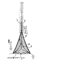
切除装置
装置10とともに用いることのできるRF切除装置12の例を図2A及び図2Bに示す。その種の切除装置は、米国特許第5,769,880号及び米国特許出願第09/103,072号に示されて説明されており、各々を参考としてここに組み入れる。同様な装置として、Novacept社、パロアルト、カリフォルニア州から入手できるNovaSure切除装置がある。当然であるが、その穿孔装置は、他の医療用装置と組み合わせて用いることができ、また、そのような代替装置は、加熱された流体が、対象となる体腔内に置かれたバルーンを通って循環されるような熱的切除装置、または切除以外の処置のために用いられる他の装置を備える。別の例としては、その装置は、2つの医療用装置、つまり、膨張媒体を供給する際の用いられる装置と、体の組織を処置する際に用いられる装置とを備える。さらに別の例では、処置装置を装置10とは別に設けることができる。
【0010】
切除装置12は、RF切除エネルギーを体腔の内壁に供給とともに、切除の間に生じた水分(例えば蒸気)を、望ましくは吸引を用いて、体の組織から外部に抜き取るようにするように構成されている。その装置12のその水分移送の特徴は、切除位置から蒸気を除去することで、そうでなければその蒸気が原因となったであろう熱的切除の量を減少させるという点で有利である。切除の深さにわたるより優れた制御が、熱的条件によるのではなく、RFエネルギーのみ(又は主に)によって切除を行うようにすることによって達成される。
【0011】
装置12はRFアプリケーターヘッド36、シース38及びハンドル40を備える。アプリケーターヘッド36は、そのアプリケーターヘッド36に流線型の外形(図2A)が与えられるようにシース38内に滑るようにして配置され、それにより、その装置は容易に体腔(例えば、子宮腔)に挿入することができる。一旦アプリケーター36が体腔内に挿入されると、ハンドル40は、アプリケーターヘッド36が、シース38の末端から延出し、さらに、体の組織と接触するために図2Aに示す位置まで拡張するように操作される。
【0012】
図2Bを参照すると、そこには明りょう化のためにシース38は示してなく、アプリケーターヘッド36が、シース38内に滑るようにして配置されたチューブ42の長さの末端から延出されている。アプリケーターヘッド36は、外側電極アレー44と、組織と接触する位置に置くようにそのアレーを拡張及び伸張するように用いる内側偏向機構46とを含む。
【0013】
アレー44は望ましくは伸縮自在な金属被覆された織地メッシュから形成されており、それは望ましくは金又は他の導電性材料によってメッキされたナイロン及びスパンデックスニットから編まれる。1つのアレー構造では、そのニットは、スパンデックスの単糸とともに編まれたナイロンの3つの単繊維から形成される。スパンデックスの各単糸はそれの周りに巻かれた5つのナイロン単繊維の二重のらせんを持つ。
【0014】
その拡張した状態では、アレー44は、互いに離隔された一対の幅広面48(その1つを図2Bに示す)を含み、狭い側面(図示せず)が、側面に沿った幅広面48とアプリケーターヘッド36の末端との間に存在し、端面52がアプリケーターヘッド36の末端にある幅広面48の間に延在する。
【0015】
アプリケーターヘッドに他の技術のエッチングを行うことによって絶縁領域(図示せず)を形成してメッシュを電極領域に分割している。
【0016】
アレーは絶縁された領域によって別々の電極構造に分割することができる。望ましい構造では、幅広面の各々に2つの電極を形成することによって絶縁領域がアプリケーターを4つの電極に分割する。
【0017】
偏向機構46及びその展開構造は電極アレー44内に囲まれている。外側の下位チューブ58がチューブ42から延出し、内側の下位チューブ60が下位チューブ58内に滑動自在で同軸的に配置されている。下位チューブ60は二重の管腔チューブで、それは以下に説明するように空気式のサブシステムに結合されている。
【0018】
複数の長手方向に間隔を置く孔(図示せず)が各湾曲部62に形成されている。使用中に、RF発生装置14に配置されていて下位チューブ58に流体的に結合された真空源を用いて、それらの孔を経由して水分をその湾曲部を通過させ、さらに下位チューブ58の露出した末端部から抜き取ることができる。
【0019】
各湾曲部62は望ましくはRFエネルギーを体の組織に供給するためにアレー44に結合された導電性領域を備える。例えば、銅製テープの細片(図示せず)又は他の導電性部材が各湾曲部の対向面に沿って延在することができる。導体のリード(図示せず)が、電気的に細片に接続され、チューブ42を通過してRF発生装置に取り付け可能な電気的ケーブルまで延出する。
【0020】
使用の間、各導体上の1つの導電性細片が導体のリードを経由してRF発生装置上の1つの端子に電気的に結合され、他の細片が反対の端子に電気的に接続され、それにより、アプリケーターのヘッド上のアレーが交互の正及び負の極性の領域を持つことができるようになる。
【0021】
湾曲部の導電性領域(例えば、銅製細片)と電極との間で適切な整列を保証してそれら2つの間に電気的接触を維持することは重要である。より糸(ナイロンでよい)のストランドは、望ましくは、アレーを経由して湾曲部の周囲に縫われて導電性領域が電極との整列から外れることを防止する。
【0022】
切除装置を用いている間、アプリケーターヘッド36は子宮に挿入され、そのとき、シース38はアレー44を覆ってアプリケーターヘッド36を線形状態に押し付ける。一旦アプリケーターヘッドが子宮内に置かれると、ハンドルを用いてシースを引っ込めてアレーをその展開した状態まで開く。真空源30(図1)が起動されると、下位チューブ60の吸引が行われる。吸引によって子宮の組織を引っ張ってアレー44と接触させるようにする。
【0023】
RF発生装置14によって電極アレー44に切除エネルギーが供給される。組織は、RFエネルギーが電極56a−dから組織に送られると加熱され、それにより水分が組織から放出される。真空源によって、子宮腔から下位チューブ60に水分が抜き取られる。水分の抜き取りは、水分が湾曲部と子宮の側壁との間に捕捉されないようにすることによって、湾曲部に形成された孔によって容易に行うことができる。
【0024】
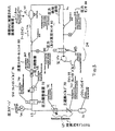
空気式サブシステム
流体/ガス源16、圧力検知装置24及び関連する構成要素を図3に示す。圧力検知装置24の構成要素の各々が、望ましくは、RF発生装置14のマイクロプロセッサ34に接続されているが、明りょう化のために、マイクロプロセッサは図3には示さない。圧力変換器、ソレノイドバルブ及び真空ポンプのすべてがマイクロプロセッサによって接続されている。
【0025】
以下に説明する実施例においては、2つのライン(ソースライン22及び圧力検知/信号ライン26)の役割は、穿孔検出のため以外はRF切除の間は別の役割を発揮するということも重要である。特に、穿孔検出のための信号ライン26は切除のための吸引ラインとして機能する。穿孔のためのソースライン22は切除のための真空信号ラインとして機能する。
【0026】
ソースライン22に沿った構成を最初に説明する。流体/ガス源16は望ましくは使い捨て可能なCO2シリンダーで、25℃で約850psiを提供する16gmシリンダーとすることができる。そのような例の1つとして、リンデメディカルグレード16gmのシリンダーがある。そのシリンダーはLeland Model50033等の圧力レギュレータ68に取り外し自在に取り付けられている。レギュレータ68は主遮断バルブ70と約60psiの制御圧力を持つ圧力調整部72とを備える。SenSym モデルASCX100DN等のような圧力ゲージ74がソースライン22に流体的に接続されている。圧力ゲージ74は、流体/ガスの残りの量が少ないとき、又は使用者がバルブ68を開けなかったときを検知するために、流体/ガス源16内に残っている圧力を監視する。
【0027】
ソレノイドバルブ76は圧力レギュレータ68の下流のソースライン22に沿って配置されている。バルブ76は、腔評価手続が実行されているときを除いて、閉じた状態に置かれていてライン22を通過してガスが流れることを阻止する。Airtrol R−920シリーズのレギュレータのような第2の圧力レギュレータ78が、バルブ76の下流に置かれていて、腔評価手続の間、ライン22内の圧力を約90+/−10mmHgまで減少させる。レギュレータ78の下流に配置されている流れ制御オリフィス80は、ライン14内の流れを100+/−10scc/min(基本単位cc/min)まで制限する。オリフィス80の上流の圧力センサーは、圧力の制限(例えば、約100mmHg)を超えたか否かを監視する。その制限を超えた場合には、そのセンサーからの出力信号によって可聴警報が出されて、ソレノイドバルブ76がオフに切り換えられる。オリフィス80の下流には、ソースライン22が、例えば柔軟なTygonチューブを用いて、切除装置12の導入シース38(図2B)に接続されている。その導入シースは、ガスを処置すべき体腔BCに供給するために、体腔BCの内面(子宮腔の場合には例えば内部の穴)に設けられる。
【0028】
圧力検出ライン26に沿った構成に戻ると、圧力信号ライン26が、例えば、Tygonチューブを用いて流体的に下位チューブ60の孔に接続されている。医療用装置12の下流には例えばSenSym ACSX05DNのような圧力センサー84がある。腔の評価手続の間、センサー84が圧力信号ライン26内の圧力を監視して信号をマイクロプロセッサ34に供給する。マイクロプロセッサ34は、次に、体腔BC内の圧力が所定のしきい値に達することができなかった(体腔内に穿孔があることを表す)か否か、又は、所定の時間にわたってそのしきい値を保持できたか(体腔が穿孔を持たないことを表す)否かを決定する。
【0029】
圧力センサー84のさらに下流には真空ポンプ86がある。穿孔の検出が不要な間、真空ポンプ86は、前の切除装置と題する段落で説明したように医療用装置21の水分移送機能を実行するように用いられる。
【0030】
第2のソレノイドバルブ88が真空ポンプ86の上流に設けられている。そのバルブ88は、腔の評価の間を除いて通常開かれている。真空ポンプの排気ラインは、作動していないとき(腔の評価手続の間を含めて)には気密にされていないので、そのバルブ88は真空ポンプを通ってのリークを防ぐために圧力信号ラインを閉じるために用いられている。
【0031】
この装置の動作を説明する簡略化した状態図を図4に示す。動作はバルブ76が閉じた状態かつバルブ88が開かれた状態から開始される。装置の使用の準備状態では、CO2シリンダー16がRF発生装置の空気式サブシステム(図3)上の適当な受取り装置に接続されている。発生装置へのパワーがオン状態に切り換えられる。圧力ゲージ74が、CO2シリンダー16とバルブ76との間をつなぐ圧力/監視ライン22の部分内の圧力を検出する。利用者が主CO2遮断バルブ70を開かなかった場合、又は、ゲージ74によって検出された圧力が特定の圧力よりも小さかった場合には、可聴警報が鳴って、低圧ガス状態であることを示す。低圧ガス状態が検出されない場合には、利用者は切除装置12をRF発生装置14に接続する。
【0032】
装置は、利用者が切除装置12をRF発生装置に接続するまで、「接続待ち」状態に保持される(ステップ102)。切除装置が電源に接続されると、それはマイクロスイッチ又は同様なものを作動し、それはマイクロプロセッサに切除装置が接続されていることを警告する。装置を接続すると自動的に「CO2放出」サイクルが開始される(ステップ104)。その放出サイクルの間、バルブ76が開かれてCO2を装置に流してその装置から空気を排除する。その放出サイクルは装置から空気を放出するのに十分な時間、約10秒程度継続する。その放出サイクルの間、空気が腔内に供給されることを防ぐために、利用者は、可聴及び可視の指示装置から、体腔に装置を挿入しないように警告を受ける。事前の安全策として、RFコントローラの一部である真空ポンプが、放出の間、数秒ごとに間欠駆動される。利用者が切除装置を体腔内に挿入すると、真空ポンプは放出の間体内に供給された空気を排出する。
【0033】
放出サイクルの間及び装置が体腔内に挿入されている間、切除装置は閉じられ、電極アレーの極が互いに接触する状態になる。低電圧信号が切除装置に印加され、それは、DC短絡を検知することによって極が接触していることを検出する。放出サイクルが完了した後、システムは、DC短絡の状態の終わりを監視することによって、装置が患者内に展開されることを待つ(ステップ106)。一度利用者が装置を子宮腔似挿入し、アレーを開くと、システムはDC短絡状態がもはや存在しないことを検出する。事前の安全策として、穿孔検出サイクルは、DC短絡状態が終了するまで開始することはできない。この点で、RFエネルギーの印加の前に完了すべき最後の操作は穿孔検出サイクルである。
【0034】
放出サイクルの完了から穿孔検出テストの開始までは、連続する低レベルのCO2の流れを切除装置内に循環させて源及び圧力信号ラインを開いて遮断から開放させる。
【0035】
次に、システムが、ユーザーがフットスイッチ32を押すのを待つ(「フットスイッチ待ち」ステップ108)。フットスイッチが押されると、30秒タイマーが起動し(「タイマーのリセット」)、穿孔検出テスト110が開始される(「圧力テストの実行」)。バルブ88が真空ポンプ86を閉じるように動かされてそれを通り抜けることによる圧力の低下が阻止される。それが既に開かれている場合には、バルブ76が開かれて、CO2が医療装置12を通り抜けて体腔内に流れ込むことができるようになる。ゲージ84でのある力が上昇して4秒間にわたって50mmHgを超えるように維持されるときには、テストは合格し、システムは「パススルー」状態に移動する。(システムは選択的に腔に圧力を加え、次に、所定の時間内に監視している圧力が既定のレベルより低くなって穿孔が存在する可能性を示すか否かを検出するという点に注目すべきである。)
「パススルー」では、CO2が遮断されて、真空ポンプがバルブ88を再開することによって再駆動される。イネーブルボタン33が押されると(自動モード)、腔評価サイクルが完了して合格しているときにはRFパワー114(「パワーの印加」)が自動的にアレー44に供給される。イネーブルボタンが押されない場合(半自動モード)には、システムは「パススルー」状態を通過して移動してフットスイッチ112の操作を待つ(「フットスイッチ待ち」)。ユーザーがボタンを押すと、RF発生装置が作動可能になり、次にフットスイッチ32を押すとRFパワー114が供給できるようになる。
【0036】
30秒タイマーが終了した後に腔評価テストが合格していない場合には、可聴音声及び可視指示装置が即座に作動する。システムはテスト失敗状態に維持され(ステップ116)、利用者の別の行動を待つ。利用者がフットスイッチを押すと、システムは初期の待機状態にリセットされ(ステップ108)、CO2ガスの流れが遮断される。利用者は所望に応じて何度も腔評価シーケンスを試みることができる。
【0037】
別の例では、1又は2以上の腔評価手続が実行されて失敗すると、利用者はシステムを解除することを選択して、そのシステムが、失敗した腔評価テストに関わらずRFエネルギーを供給することができるようにする。そうするために、利用者はイネーブルボタン33を押して6秒間保持する。圧力チェックは、その特徴を利用する前に、少なくとも1回は試してみなければならないということには注意すべきである。利用者が腔評価を無効にすると、システムは「パススルー」状態に移動してフットスイッチをステップ112で待つ。
【0038】
上記のシーケンスの間のどの時間にでも、利用者が切除装置を選択しなければならない場合には、DC短絡はRF発生装置のDC短絡検知回路によって電極アレー内で検出される。装置を閉じることによって、穿孔テストの状態が失敗に変わり、システムが「展開待ち」の状態(ステップ106)にリセットされる。その後、システムは、アレーがサイド開かれると、腔評価の実行を要求する。これにより、RFエネルギーの印加の前に実行される最後のステップは穿孔検知テストであることが保証される。つまり、利用者が、テストを成功させることができた後にさまざまな理由によって装置を閉じて取り除くことを決定したときには、穿孔検知テストは、装置が体腔内で展開されると再度実行されなければならない。この要求によって、利用者が、装置が体の外にある状態で腔評価を行い、その後装置を挿入し、テストを解除し、さらに、体腔内で腔評価を十分に実行することなく切除を行うことも防止することができる。
【0039】
さらなる安全のために、穿孔検出システムは、ガス又は一般的な塩水のような液体の中からCO2を優先的に用いる。圧力及び流れの範囲は、公知の注入器用のガイダンスの書面に従う。子宮穿孔検出の場合には、それらの範囲は子宮フレーター(hysteroflator)のガイダンスの書面に従う。他の構成も可能であるが、評価すべき腔は源と圧力信号ラインとの間に直列に置かなければならない。このようにすると、チューブのよじれや他の問題はテストの失敗の結果にはつながらない。さらに、システムは、体腔内に正常に挿入される装置の寸法の範囲を超える穿孔を検出することができる(例えば、直径15mmから1mm未満程度まで)。
【0040】
子宮腔ないの穿孔を確実に検知するために、その場合の圧力のしきい値は望ましくはファローピウス管の平均損傷圧力以下に保持される。
【0041】
システムの利用の容易さを改善するいくつかの特徴がある。第1には、医師はシーケンス内のどの時間にでも穿孔テストを開始又は停止することができる。第2に、マイクロプロセッサ34は、閉じられた装置と体腔内でかすかな動きを受ける装置の間の差を識別して、完了したテスト状況が覆される可能性を減少させることができる。最後に、システムは図2aに示すカラー組立体63を備えており、それは、漏れの存在が確認されたときに、体腔BCへの浸入を封じて正確でないテストの失敗の可能性を減少させることができる。
【0042】
これまでの説明は、子宮内の組織の切除に用いることのできる装置を持つ穿孔検出システムに関するが、本願発明は他の体腔内の穿孔の穿孔検出に応用でき、さらに、切除以外の処置に有用な医療装置を持つ穿孔検出システムに応用することができる。さらに、そのシステムは特定の実施例を参照しながら説明したが、本願発明を実行するために多くの他の構成を用いることができる。当業者は、ここで説明した実施例からこの技術を逸脱することなく多くの変形が可能であることを確実に理解するであろう。すべてのそのような変形例は特許請求の範囲に包含される。
【図面の簡単な説明】
【図1】 図1は本願発明の原理を用いる穿孔検出装置の概略を示す図である。
【図2】 図2Aは、図1の装置とともに用いることのできる切除機器の側面図である。
図2Bは、図2Aの切除装置のRFアプリケーターのヘッドの平面図である。
【図3】 図3は図1の装置の空気式のサブシステムの概略図である。
【図4】 図4は本願発明の穿孔検出及びインターロックの特徴を用いるモードを示す簡略化された状態図である。[0001]
BACKGROUND OF THE INVENTION
The present invention relates to the field of systems of methods for detecting the presence of perforations in a body cavity. In particular, the present invention relates to an apparatus and method for detecting whether pressure can be applied to a body cavity to maintain the pressurized state of the body cavity.
[0002]
[Prior art]
There are several medical procedures performed within a body cavity. One example of such a procedure is tissue resection. Resection of the inner wall of an organ in the body is a procedure that involves heating the inner wall of the organ to a temperature that destroys the cells of the inner wall or coagulates tissue proteins. Such treatment can be performed as a treatment for one of many situations such as chronic bleeding of the endometrial layer or abnormalities of the mucosal layer of the gallbladder. Current methods of accomplishing ablation include resistance to circulation of heated fluid inside the organ (directly or inside the balloon), laser treatment of the inner wall of the organ, and application of RF energy to the tissue to be ablated. Heating is included.
[0003]
The ablation procedure is sometimes performed without an endoscope and without direct viewing. For example, endometrial resection typically involves inserting an elongated resection instrument into the patient's cervix without using a uteroscope. As can be expected, if there is a perforation in the uterus, inadvertently, the ablation instrument will penetrate the perforation and exit the uterus to the intestine. Although this is rare, there may be a perforation in the body cavity before the doctor applies force with a treatment instrument such as a resection instrument because of the injury that could result from such an event. It would be highly desirable to provide a mechanism that can evaluate whether or not to do so.
[0004]
[Means for Solving the Problems]
The present invention is an apparatus and method for detecting perforations in a body cavity. According to the method of the present invention, a fluid (liquid or gas) is supplied into a body cavity and a little pressure is applied to the body cavity. The pressure sensing device monitors the pressure in the body cavity over a predetermined test period. If the pressure in the body cavity is not substantially maintained within the test period, the physician is alerted to examine the body cavity further for perforation before initiating treatment within the body cavity. In a preferred example of the device, a medical treatment device such as an RF ablation device is provided with a perforation detection function. The device desirably includes an interlock that prevents delivery of RF power when a perforation detection procedure is not being performed.
[0005]
DETAILED DESCRIPTION OF THE INVENTION
The perforation detection device 10 (also referred to as “body cavity evaluation device”) using the principle of the present invention will be described as forming part of an RF ablation device used to ablate tissue in a body cavity such as the uterus. However, it should be recognized that the
[0006]
Briefly, the
[0007]
The body
[0008]
The body cavity evaluation interlock 20 further includes an interlock device 28 that prevents a procedure using the
[0009]
Ablation device An example of an
[0010]
The
[0011]
[0012]
Referring to FIG. 2B, the
[0013]
The array 44 is preferably formed from a stretchable metallized woven mesh, which is preferably knitted from nylon and spandex knit plated with gold or other conductive material. In one array structure, the knit is formed from three single fibers of nylon knitted with spandex single yarn. Each single yarn of spandex has a double helix of five nylon monofilaments wound around it.
[0014]
In its expanded state, the array 44 includes a pair of wide surfaces 48 (one of which is shown in FIG. 2B) spaced apart from each other, with a narrow side surface (not shown) extending from the wide surface 48 along the side surface to the applicator. Between the distal end of the head 36, the end face 52 extends between the wide surface 48 at the distal end of the applicator head 36.
[0015]
Insulating regions (not shown) are formed by etching the applicator head using other techniques to divide the mesh into electrode regions.
[0016]
The array can be divided into separate electrode structures by insulated regions. In the preferred structure, the insulating region divides the applicator into four electrodes by forming two electrodes on each of the wide surfaces.
[0017]
The deflection mechanism 46 and its unfolded structure are enclosed within the electrode array 44. An outer
[0018]
A plurality of holes (not shown) spaced in the longitudinal direction are formed in each curved portion 62. In use, a vacuum source disposed on the
[0019]
Each bend 62 preferably comprises a conductive region coupled to the array 44 for supplying RF energy to body tissue. For example, a strip of copper tape (not shown) or other conductive member can extend along the opposing surface of each bend. Conductor leads (not shown) are electrically connected to the strip and extend through the tube 42 to an electrical cable that can be attached to the RF generator.
[0020]
During use, one conductive strip on each conductor is electrically coupled to one terminal on the RF generator via the conductor leads and the other strip is electrically connected to the opposite terminal. This allows the array on the applicator head to have alternating positive and negative polar regions.
[0021]
It is important to ensure proper alignment between the conductive region of the bend (eg, copper strip) and the electrode to maintain electrical contact between the two. Strands of twisted yarn (which may be nylon) are desirably sewn around the bend via the array to prevent the conductive region from being out of alignment with the electrode.
[0022]
While using the ablation device, the applicator head 36 is inserted into the uterus, when the
[0023]
Ablation energy is supplied to the electrode array 44 by the
[0024]
Pneumatic subsystem The fluid / gas source 16,
[0025]
In the embodiment described below, it is also important that the roles of the two lines (
[0026]
First, the configuration along the
[0027]
The solenoid valve 76 is disposed along the
[0028]
Returning to the configuration along the pressure detection line 26, the pressure signal line 26 is fluidly connected to the bore of the lower tube 60, for example using a Tygon tube. Downstream of the
[0029]
A vacuum pump 86 is further downstream of the pressure sensor 84. While detection of perforations is not required, the vacuum pump 86 is used to perform the moisture transfer function of the medical device 21 as described in the previous paragraph entitled Resection Device.
[0030]
A
[0031]
A simplified state diagram illustrating the operation of this apparatus is shown in FIG. The operation starts with the valve 76 closed and the
[0032]
The device is held in a “waiting for connection” state until the user connects the
[0033]
During the discharge cycle and while the device is inserted into the body cavity, the ablation device is closed and the poles of the electrode array are in contact with each other. A low voltage signal is applied to the ablation device, which detects that the poles are in contact by detecting a DC short circuit. After the discharge cycle is complete, the system waits for the device to be deployed in the patient by monitoring the end of the DC short circuit condition (step 106). Once the user inserts the device into the uterine cavity and opens the array, the system detects that the DC short circuit condition no longer exists. As a precautionary measure, the perforation detection cycle cannot be started until the DC short circuit condition ends. In this regard, the last operation to be completed before the application of RF energy is the perforation detection cycle.
[0034]
From the completion of the discharge cycle until the start of the perforation detection test, thereby released from the low-level flow of CO 2 consecutive circulated into the ablation device blocking open source and pressure signal lines.
[0035]
Next, the system waits for the user to press the foot switch 32 (“wait for foot switch” step 108). When the foot switch is pressed, a 30 second timer is started (“timer reset”) and the
In “pass-through”, CO 2 is shut off and the vacuum pump is re-driven by restarting
[0036]
If the cavity assessment test does not pass after the 30 second timer expires, the audible audio and visual indicator will be activated immediately. The system is maintained in a test failure state (step 116) and awaits another user action. When the user presses the foot switch, the system is reset to the initial standby state (step 108) and the flow of CO 2 gas is shut off. The user can try the cavity evaluation sequence as many times as desired.
[0037]
In another example, if one or more cavity assessment procedures are performed and fail, the user chooses to release the system, which provides RF energy regardless of the failed cavity assessment test. To be able to. To do so, the user presses the enable button 33 and holds it for 6 seconds. It should be noted that the pressure check must be tried at least once before using its features. If the user disables cavity evaluation, the system moves to the “pass-through” state and waits for a footswitch at step 112.
[0038]
If at any time during the above sequence the user must select an ablation device, a DC short circuit is detected in the electrode array by the DC short circuit detection circuit of the RF generator. Closing the device changes the state of the drilling test to failure and resets the system to the “waiting for deployment” state (step 106). The system then requests that a cavity assessment be performed when the array is side-opened. This ensures that the last step performed before application of RF energy is a perforation detection test. That is, if the user decides to close and remove the device for various reasons after the test has been successful, the perforation detection test must be performed again when the device is deployed in the body cavity . This request allows the user to perform a cavity assessment with the device outside the body, then insert the device, release the test, and perform a resection without fully performing the cavity assessment within the body cavity This can also be prevented.
[0039]
For added safety, the perforation detection system preferentially uses CO 2 from liquids such as gas or common brine. Pressure and flow ranges follow the written guidance for known injectors. In the case of uterine perforation detection, these ranges follow the written guidance of the uteroflater. Other configurations are possible, but the cavity to be evaluated must be placed in series between the source and the pressure signal line. In this way, kinking of tubes and other problems will not result in test failures. Furthermore, the system can detect perforations that exceed the size range of devices that are normally inserted into body cavities (eg, from 15 mm to less than 1 mm in diameter).
[0040]
In order to reliably detect perforation of the uterine cavity, the pressure threshold in that case is preferably kept below the average damage pressure of the Fallopian tube.
[0041]
There are several features that improve the ease of use of the system. First, the physician can start or stop the perforation test at any time in the sequence. Second, the microprocessor 34 can identify the difference between the closed device and the device undergoing subtle movement in the body cavity, reducing the likelihood that a completed test situation will be overturned. Finally, the system includes a collar assembly 63 as shown in FIG. 2a that seals entry into the body cavity BC and reduces the possibility of inaccurate test failures when the presence of a leak is confirmed. Can do.
[0042]
Although the above description relates to a perforation detection system having a device that can be used for excision of tissue in the uterus, the present invention can be applied to perforation detection of perforations in other body cavities and is useful for procedures other than excision. It can be applied to a perforation detection system having a medical device. Moreover, while the system has been described with reference to particular embodiments, many other configurations can be used to implement the invention. Those skilled in the art will certainly appreciate that many variations are possible from the embodiments described herein without departing from this technique. All such variations are encompassed by the claims.
[Brief description of the drawings]
FIG. 1 is a diagram showing an outline of a perforation detection apparatus using the principle of the present invention.
2A is a side view of an ablation device that can be used with the apparatus of FIG.
2B is a plan view of the RF applicator head of the ablation device of FIG. 2A.
FIG. 3 is a schematic diagram of the pneumatic subsystem of the apparatus of FIG.
FIG. 4 is a simplified state diagram illustrating modes using the perforation detection and interlock features of the present invention.
Claims (17)
流体加圧源と、
体腔に挿入可能な医療用器具であって、前記流体加圧源に流体的に接続されていて流体を前記体腔に供給して圧力を上昇させる医療用器具と、
前記体腔に供給された流体の圧力を検出するように配置された圧力センサーと、
該圧力センサーに接続されていて、前記圧力センサーによって監視された圧力が、既定のレベルを超えて上昇せず、または、既定の時間の長さの間既定のレベルを超えて維持されない場合に利用者に警告を与えるための通知信号を発生させるフィードバック手段とを備える装置。A device for detecting the presence of a perforation in a body cavity,
A fluid pressurization source;
A medical instrument that can be inserted into a body cavity, wherein the medical instrument is fluidly connected to the fluid pressurization source and supplies fluid to the body cavity to increase the pressure ;
A pressure sensor arranged to detect the pressure of the fluid supplied to the body cavity;
Used when connected to the pressure sensor and the pressure monitored by the pressure sensor does not rise above a predetermined level or is not maintained above a predetermined level for a predetermined amount of time A feedback means for generating a notification signal for giving a warning to a person.
該電子機器に接続されていて、前記体腔内の穿孔の存在を利用者に警告する通知信号を発生するための前記フィードバック信号に応答するフィードバック装置とを備える装置。2. The apparatus of claim 1, wherein the feedback means is an electronic device electrically connected to the pressure sensor, wherein the monitored pressure does not increase and exceeds a predetermined level for a predetermined length of time. An electronic device that generates a feedback signal if not maintained
A feedback device connected to the electronic device and responsive to the feedback signal for generating a notification signal to alert a user of the presence of a perforation in the body cavity.
流体加圧源と、
体腔に挿入可能で、前記流体加圧源に流体的に接続されていて流体を前記体腔に供給して圧力を上昇させる医療用器具であって、体腔の内部表面を処置するための処置要素を含む医療用器具と、
前記体腔に供給された前記流体の圧力を検出するように配置された圧力センサーと、
該圧力センサーに接続されていて、該圧力センサーによって監視された圧力が、既定のレベルを超えて上昇せず、または、既定の時間の長さの間既定のレベルを超えて維持されない場合に利用者を警告するために通知信号を発生するフィードバック手段とを備える装置。An apparatus for detecting the presence of a perforation in a body cavity and treating the interior of the body cavity,
A fluid pressurization source;
A medical device that is insertable into a body cavity and is fluidly connected to the fluid pressurization source to supply fluid to the body cavity to increase pressure, and a treatment element for treating an internal surface of the body cavity Including medical instruments, and
A pressure sensor arranged to detect the pressure of the fluid supplied to the body cavity;
Used when connected to the pressure sensor and the pressure monitored by the pressure sensor does not rise above a predetermined level or is not maintained above a predetermined level for a predetermined amount of time And feedback means for generating a notification signal to alert the person.
Applications Claiming Priority (3)
| Application Number | Priority Date | Filing Date | Title |
|---|---|---|---|
| US16448299P | 1999-11-10 | 1999-11-10 | |
| US60/164,482 | 1999-11-10 | ||
| PCT/US2000/042052 WO2001035844A2 (en) | 1999-11-10 | 2000-11-10 | System and method for detecting perforations in a body cavity |
Publications (3)
| Publication Number | Publication Date |
|---|---|
| JP2003513742A JP2003513742A (en) | 2003-04-15 |
| JP2003513742A5 JP2003513742A5 (en) | 2007-12-06 |
| JP4216501B2 true JP4216501B2 (en) | 2009-01-28 |
Family
ID=22594694
Family Applications (1)
| Application Number | Title | Priority Date | Filing Date |
|---|---|---|---|
| JP2001537641A Expired - Fee Related JP4216501B2 (en) | 1999-11-10 | 2000-11-10 | Device for detecting perforations in body cavities |
Country Status (8)
| Country | Link |
|---|---|
| US (4) | US6554780B1 (en) |
| EP (1) | EP1229829B1 (en) |
| JP (1) | JP4216501B2 (en) |
| AT (1) | ATE383104T1 (en) |
| AU (1) | AU2924101A (en) |
| DE (1) | DE60037747T2 (en) |
| ES (1) | ES2299447T3 (en) |
| WO (1) | WO2001035844A2 (en) |
Families Citing this family (220)
| Publication number | Priority date | Publication date | Assignee | Title |
|---|---|---|---|---|
| US7604633B2 (en) * | 1996-04-12 | 2009-10-20 | Cytyc Corporation | Moisture transport system for contact electrocoagulation |
| US8551082B2 (en) | 1998-05-08 | 2013-10-08 | Cytyc Surgical Products | Radio-frequency generator for powering an ablation device |
| US20040073155A1 (en) * | 2000-01-14 | 2004-04-15 | Broncus Technologies, Inc. | Methods and devices for maintaining patency of surgically created channels in tissue |
| ES2299447T3 (en) * | 1999-11-10 | 2008-06-01 | Cytyc Surgical Products | SYSTEM TO DETECT PERFORATIONS IN A BODY CAVITY. |
| US6558385B1 (en) | 2000-09-22 | 2003-05-06 | Tissuelink Medical, Inc. | Fluid-assisted medical device |
| US6689131B2 (en) | 2001-03-08 | 2004-02-10 | Tissuelink Medical, Inc. | Electrosurgical device having a tissue reduction sensor |
| US7811282B2 (en) | 2000-03-06 | 2010-10-12 | Salient Surgical Technologies, Inc. | Fluid-assisted electrosurgical devices, electrosurgical unit with pump and methods of use thereof |
| US6702810B2 (en) | 2000-03-06 | 2004-03-09 | Tissuelink Medical Inc. | Fluid delivery system and controller for electrosurgical devices |
| US8048070B2 (en) | 2000-03-06 | 2011-11-01 | Salient Surgical Technologies, Inc. | Fluid-assisted medical devices, systems and methods |
| JP4926359B2 (en) * | 2000-05-03 | 2012-05-09 | シー・アール・バード・インコーポレーテッド | Apparatus and method for mapping and cauterization in electrophysiological procedures |
| US20050060042A1 (en) * | 2001-09-04 | 2005-03-17 | Broncus Technologies, Inc. | Methods and devices for maintaining surgically created channels in a body organ |
| US7708712B2 (en) | 2001-09-04 | 2010-05-04 | Broncus Technologies, Inc. | Methods and devices for maintaining patency of surgically created channels in a body organ |
| EP1460945B1 (en) * | 2001-09-14 | 2013-01-09 | ArthroCare Corporation | Electrosurgical apparatus for tissue treatment & removal |
| CA2642135C (en) | 2001-11-21 | 2013-04-09 | E-Z-Em, Inc. | Device, system, kit or method for collecting effluent from an individual |
| US20110306997A9 (en) * | 2002-02-21 | 2011-12-15 | Roschak Edmund J | Devices for creating passages and sensing for blood vessels |
| WO2004039416A2 (en) | 2002-10-29 | 2004-05-13 | Tissuelink Medical, Inc. | Fluid-assisted electrosurgical scissors and methods |
| US8308682B2 (en) | 2003-07-18 | 2012-11-13 | Broncus Medical Inc. | Devices for maintaining patency of surgically created channels in tissue |
| DE202004021944U1 (en) | 2003-09-12 | 2013-07-16 | Vessix Vascular, Inc. | Selectable eccentric remodeling and / or ablation of atherosclerotic material |
| US20050059992A1 (en) * | 2003-09-17 | 2005-03-17 | Leiboff Arnold R. | Air introduction device for anastomotic leak testing |
| US7988690B2 (en) | 2004-01-30 | 2011-08-02 | W.L. Gore & Associates, Inc. | Welding systems useful for closure of cardiac openings |
| US7727232B1 (en) | 2004-02-04 | 2010-06-01 | Salient Surgical Technologies, Inc. | Fluid-assisted medical devices and methods |
| US7918869B2 (en) | 2004-05-07 | 2011-04-05 | Usgi Medical, Inc. | Methods and apparatus for performing endoluminal gastroplasty |
| CA2591543A1 (en) * | 2004-07-19 | 2006-02-09 | Broncus Technologies, Inc. | Methods and devices for maintaining patency of surgically created channels in a body organ |
| US8409167B2 (en) | 2004-07-19 | 2013-04-02 | Broncus Medical Inc | Devices for delivering substances through an extra-anatomic opening created in an airway |
| US20060100579A1 (en) * | 2004-07-23 | 2006-05-11 | Usgi Medical Inc. | Apparatus and methods for controlling pressurization of a body cavity |
| US9974607B2 (en) | 2006-10-18 | 2018-05-22 | Vessix Vascular, Inc. | Inducing desirable temperature effects on body tissue |
| US9713730B2 (en) | 2004-09-10 | 2017-07-25 | Boston Scientific Scimed, Inc. | Apparatus and method for treatment of in-stent restenosis |
| US8396548B2 (en) | 2008-11-14 | 2013-03-12 | Vessix Vascular, Inc. | Selective drug delivery in a lumen |
| US7731712B2 (en) * | 2004-12-20 | 2010-06-08 | Cytyc Corporation | Method and system for transcervical tubal occlusion |
| US20060161076A1 (en) * | 2005-01-06 | 2006-07-20 | Diamics, Inc. | Systems and methods for collection of cell clusters |
| US20060189893A1 (en) * | 2005-01-06 | 2006-08-24 | Diamics, Inc. | Systems and methods for detecting abnormal cells |
| US7918795B2 (en) * | 2005-02-02 | 2011-04-05 | Gynesonics, Inc. | Method and device for uterine fibroid treatment |
| US7674260B2 (en) | 2005-04-28 | 2010-03-09 | Cytyc Corporation | Emergency hemostasis device utilizing energy |
| US9259267B2 (en) | 2005-09-06 | 2016-02-16 | W.L. Gore & Associates, Inc. | Devices and methods for treating cardiac tissue |
| US7797056B2 (en) | 2005-09-06 | 2010-09-14 | Nmt Medical, Inc. | Removable intracardiac RF device |
| US20070088388A1 (en) * | 2005-09-19 | 2007-04-19 | Opolski Steven W | Delivery device for implant with dual attachment sites |
| US7806850B2 (en) | 2005-10-24 | 2010-10-05 | Bracco Diagnostics Inc. | Insufflating system, method, and computer program product for controlling the supply of a distending media to an endoscopic device |
| US8137256B2 (en) | 2005-12-16 | 2012-03-20 | Portola Medical, Inc. | Brachytherapy apparatus |
| US20070270627A1 (en) * | 2005-12-16 | 2007-11-22 | North American Scientific | Brachytherapy apparatus for asymmetrical body cavities |
| US8876746B2 (en) | 2006-01-06 | 2014-11-04 | Arthrocare Corporation | Electrosurgical system and method for treating chronic wound tissue |
| US10058342B2 (en) | 2006-01-12 | 2018-08-28 | Gynesonics, Inc. | Devices and methods for treatment of tissue |
| US7874986B2 (en) * | 2006-04-20 | 2011-01-25 | Gynesonics, Inc. | Methods and devices for visualization and ablation of tissue |
| US11259825B2 (en) | 2006-01-12 | 2022-03-01 | Gynesonics, Inc. | Devices and methods for treatment of tissue |
| US20070161905A1 (en) * | 2006-01-12 | 2007-07-12 | Gynesonics, Inc. | Intrauterine ultrasound and method for use |
| US7815571B2 (en) * | 2006-04-20 | 2010-10-19 | Gynesonics, Inc. | Rigid delivery systems having inclined ultrasound and needle |
| US9357977B2 (en) | 2006-01-12 | 2016-06-07 | Gynesonics, Inc. | Interventional deployment and imaging system |
| US7976541B2 (en) * | 2006-02-15 | 2011-07-12 | Boston Scientific Scimed, Inc. | Contact sensitive probes with indicators |
| US10595819B2 (en) | 2006-04-20 | 2020-03-24 | Gynesonics, Inc. | Ablation device with articulated imaging transducer |
| US8206300B2 (en) | 2008-08-26 | 2012-06-26 | Gynesonics, Inc. | Ablation device with articulated imaging transducer |
| US20100056926A1 (en) * | 2008-08-26 | 2010-03-04 | Gynesonics, Inc. | Ablation device with articulated imaging transducer |
| US8019435B2 (en) | 2006-05-02 | 2011-09-13 | Boston Scientific Scimed, Inc. | Control of arterial smooth muscle tone |
| WO2007143445A2 (en) | 2006-05-30 | 2007-12-13 | Arthrocare Corporation | Hard tissue ablation system |
| US8486060B2 (en) * | 2006-09-18 | 2013-07-16 | Cytyc Corporation | Power ramping during RF ablation |
| US20080071269A1 (en) * | 2006-09-18 | 2008-03-20 | Cytyc Corporation | Curved Endoscopic Medical Device |
| EP2455036B1 (en) | 2006-10-18 | 2015-07-15 | Vessix Vascular, Inc. | Tuned RF energy and electrical tissue characterization for selective treatment of target tissues |
| CA2666663C (en) | 2006-10-18 | 2016-02-09 | Minnow Medical, Inc. | System for inducing desirable temperature effects on body tissue |
| WO2008058089A2 (en) | 2006-11-03 | 2008-05-15 | North American Scientific, Inc. | Brachytherapy device having seed tubes with individually-settable tissue spacings |
| US20080146872A1 (en) * | 2006-11-07 | 2008-06-19 | Gruber William H | Mechanical distension systems for performing a medical procedure in a remote space |
| US7846160B2 (en) | 2006-12-21 | 2010-12-07 | Cytyc Corporation | Method and apparatus for sterilization |
| US8192424B2 (en) | 2007-01-05 | 2012-06-05 | Arthrocare Corporation | Electrosurgical system with suction control apparatus, system and method |
| US8945114B2 (en) * | 2007-04-26 | 2015-02-03 | Medtronic, Inc. | Fluid sensor for ablation therapy |
| WO2009009398A1 (en) | 2007-07-06 | 2009-01-15 | Tsunami Medtech, Llc | Medical system and method of use |
| EP2198797B1 (en) | 2007-08-23 | 2011-04-13 | Aegea Medical, Inc. | Uterine therapy device |
| US8088072B2 (en) | 2007-10-12 | 2012-01-03 | Gynesonics, Inc. | Methods and systems for controlled deployment of needles in tissue |
| ES2907462T3 (en) * | 2007-10-15 | 2022-04-25 | Univ Maryland | Apparatus for use in studying a patient's colon |
| US8186877B2 (en) | 2007-12-30 | 2012-05-29 | St. Jude Medical, Atrial Fibrillation Division, Inc. | Method and system for using common subchannel to assess the operating characteristics of transducers |
| US9358063B2 (en) | 2008-02-14 | 2016-06-07 | Arthrocare Corporation | Ablation performance indicator for electrosurgical devices |
| US20090259301A1 (en) * | 2008-04-10 | 2009-10-15 | Daniel Gelbart | Detector for abnormal conditions inside body |
| US20090287081A1 (en) * | 2008-04-29 | 2009-11-19 | Gynesonics , Inc | Submucosal fibroid ablation for the treatment of menorrhagia |
| WO2010061379A1 (en) * | 2008-11-03 | 2010-06-03 | G.I. View Ltd | Remote pressure sensing system and method thereof |
| WO2010056771A1 (en) * | 2008-11-11 | 2010-05-20 | Shifamed Llc | Low profile electrode assembly |
| US9795442B2 (en) | 2008-11-11 | 2017-10-24 | Shifamed Holdings, Llc | Ablation catheters |
| WO2010056745A1 (en) | 2008-11-17 | 2010-05-20 | Minnow Medical, Inc. | Selective accumulation of energy with or without knowledge of tissue topography |
| EP2382000A2 (en) * | 2008-12-05 | 2011-11-02 | AMS Research Corporation | Devices, systems and methods for delivering fluid to tissue |
| EP2397087A3 (en) | 2009-01-30 | 2013-08-14 | Cytyc Corporation | Cervical opening sealing devices |
| US11284931B2 (en) | 2009-02-03 | 2022-03-29 | Tsunami Medtech, Llc | Medical systems and methods for ablating and absorbing tissue |
| US8262574B2 (en) | 2009-02-27 | 2012-09-11 | Gynesonics, Inc. | Needle and tine deployment mechanism |
| US8574187B2 (en) * | 2009-03-09 | 2013-11-05 | Arthrocare Corporation | System and method of an electrosurgical controller with output RF energy control |
| WO2010141500A1 (en) | 2009-06-01 | 2010-12-09 | Theranova, Llc | Methods and apparatus for treatment of a body cavity or lumen |
| US8257350B2 (en) | 2009-06-17 | 2012-09-04 | Arthrocare Corporation | Method and system of an electrosurgical controller with wave-shaping |
| EP2445568B1 (en) * | 2009-06-24 | 2020-09-23 | Kalila Medical, Inc. | Steerable medical delivery devices |
| US8394037B2 (en) | 2009-11-11 | 2013-03-12 | Minerva Surgical, Inc. | Systems and devices for evaluating the integrity of a uterine cavity |
| US8715278B2 (en) | 2009-11-11 | 2014-05-06 | Minerva Surgical, Inc. | System for endometrial ablation utilizing radio frequency |
| US9289257B2 (en) | 2009-11-13 | 2016-03-22 | Minerva Surgical, Inc. | Methods and systems for endometrial ablation utilizing radio frequency |
| US8529562B2 (en) | 2009-11-13 | 2013-09-10 | Minerva Surgical, Inc | Systems and methods for endometrial ablation |
| US8372067B2 (en) * | 2009-12-09 | 2013-02-12 | Arthrocare Corporation | Electrosurgery irrigation primer systems and methods |
| US8926629B2 (en) | 2010-02-24 | 2015-01-06 | Minerva Surgical, Inc. | Systems and methods for endometrial ablation |
| US9421059B2 (en) | 2010-04-27 | 2016-08-23 | Minerva Surgical, Inc. | Device for endometrial ablation having an expandable seal for a cervical canal |
| US20110208178A1 (en) * | 2010-02-24 | 2011-08-25 | Minerva Surgical, Inc. | Systems and methods for cervical seal |
| AU2011232335A1 (en) | 2010-03-24 | 2012-10-11 | Shifamed Holdings, Llc | Intravascular tissue disruption |
| US8747399B2 (en) | 2010-04-06 | 2014-06-10 | Arthrocare Corporation | Method and system of reduction of low frequency muscle stimulation during electrosurgical procedures |
| KR20130108067A (en) | 2010-04-09 | 2013-10-02 | 베식스 바스큘라 인코포레이티드 | Power generating and control apparatus for the treatment of tissue |
| US9192790B2 (en) | 2010-04-14 | 2015-11-24 | Boston Scientific Scimed, Inc. | Focused ultrasonic renal denervation |
| CN105105844B (en) | 2010-05-12 | 2017-12-15 | 施菲姆德控股有限责任公司 | The electrode assemblie of little profile |
| US9655677B2 (en) | 2010-05-12 | 2017-05-23 | Shifamed Holdings, Llc | Ablation catheters including a balloon and electrodes |
| US8473067B2 (en) | 2010-06-11 | 2013-06-25 | Boston Scientific Scimed, Inc. | Renal denervation and stimulation employing wireless vascular energy transfer arrangement |
| US8956348B2 (en) | 2010-07-21 | 2015-02-17 | Minerva Surgical, Inc. | Methods and systems for endometrial ablation |
| US9463062B2 (en) | 2010-07-30 | 2016-10-11 | Boston Scientific Scimed, Inc. | Cooled conductive balloon RF catheter for renal nerve ablation |
| US9358365B2 (en) | 2010-07-30 | 2016-06-07 | Boston Scientific Scimed, Inc. | Precision electrode movement control for renal nerve ablation |
| US9084609B2 (en) | 2010-07-30 | 2015-07-21 | Boston Scientific Scime, Inc. | Spiral balloon catheter for renal nerve ablation |
| US9408661B2 (en) | 2010-07-30 | 2016-08-09 | Patrick A. Haverkost | RF electrodes on multiple flexible wires for renal nerve ablation |
| US9155589B2 (en) | 2010-07-30 | 2015-10-13 | Boston Scientific Scimed, Inc. | Sequential activation RF electrode set for renal nerve ablation |
| US9943353B2 (en) | 2013-03-15 | 2018-04-17 | Tsunami Medtech, Llc | Medical system and method of use |
| US8685018B2 (en) | 2010-10-15 | 2014-04-01 | Arthrocare Corporation | Electrosurgical wand and related method and system |
| US9186208B2 (en) | 2010-10-19 | 2015-11-17 | Minerva Surgical, Inc. | Systems for endometrial ablation |
| US8974451B2 (en) | 2010-10-25 | 2015-03-10 | Boston Scientific Scimed, Inc. | Renal nerve ablation using conductive fluid jet and RF energy |
| US9220558B2 (en) | 2010-10-27 | 2015-12-29 | Boston Scientific Scimed, Inc. | RF renal denervation catheter with multiple independent electrodes |
| WO2012064864A1 (en) | 2010-11-09 | 2012-05-18 | Aegea Medical Inc. | Positioning method and apparatus for delivering vapor to the uterus |
| US9259262B2 (en) | 2010-11-09 | 2016-02-16 | Minerva Surgical, Inc. | Systems and methods for endometrial ablation |
| US9028485B2 (en) | 2010-11-15 | 2015-05-12 | Boston Scientific Scimed, Inc. | Self-expanding cooling electrode for renal nerve ablation |
| US9089350B2 (en) | 2010-11-16 | 2015-07-28 | Boston Scientific Scimed, Inc. | Renal denervation catheter with RF electrode and integral contrast dye injection arrangement |
| US9668811B2 (en) | 2010-11-16 | 2017-06-06 | Boston Scientific Scimed, Inc. | Minimally invasive access for renal nerve ablation |
| US9326751B2 (en) | 2010-11-17 | 2016-05-03 | Boston Scientific Scimed, Inc. | Catheter guidance of external energy for renal denervation |
| US9060761B2 (en) | 2010-11-18 | 2015-06-23 | Boston Scientific Scime, Inc. | Catheter-focused magnetic field induced renal nerve ablation |
| US9192435B2 (en) | 2010-11-22 | 2015-11-24 | Boston Scientific Scimed, Inc. | Renal denervation catheter with cooled RF electrode |
| US9023034B2 (en) | 2010-11-22 | 2015-05-05 | Boston Scientific Scimed, Inc. | Renal ablation electrode with force-activatable conduction apparatus |
| CA2818844C (en) | 2010-11-24 | 2016-02-16 | Bracco Diagnostics Inc. | System, device, and method for providing and controlling the supply of a distending media for ct colonography |
| US20120157993A1 (en) | 2010-12-15 | 2012-06-21 | Jenson Mark L | Bipolar Off-Wall Electrode Device for Renal Nerve Ablation |
| WO2012092558A1 (en) * | 2010-12-30 | 2012-07-05 | Hologic, Inc. | Hysteroscopic tissue removal system with improved fluid management and/or monitoring capabilities |
| US9220561B2 (en) | 2011-01-19 | 2015-12-29 | Boston Scientific Scimed, Inc. | Guide-compatible large-electrode catheter for renal nerve ablation with reduced arterial injury |
| MX341823B (en) | 2011-02-01 | 2016-09-05 | Channel Medsystems Inc | Methods and apparatus for cyrogenic treatment of a body cavity or lumen. |
| US9131597B2 (en) | 2011-02-02 | 2015-09-08 | Arthrocare Corporation | Electrosurgical system and method for treating hard body tissue |
| US9655557B2 (en) | 2011-02-04 | 2017-05-23 | Minerva Surgical, Inc. | Methods and systems for evaluating the integrity of a uterine cavity |
| US10335230B2 (en) * | 2011-03-09 | 2019-07-02 | Covidien Lp | Systems for thermal-feedback-controlled rate of fluid flow to fluid-cooled antenna assembly and methods of directing energy to tissue using same |
| US8939971B2 (en) | 2011-03-11 | 2015-01-27 | Minerva Surgical, Inc. | System and method for endometrial ablation |
| US9050102B2 (en) | 2011-03-23 | 2015-06-09 | Minerva Surgical Inc. | System and method for endometrial ablation |
| US9050103B2 (en) | 2011-03-25 | 2015-06-09 | Minerva Surgical Inc. | System and method for endometrial ablation |
| WO2012151396A2 (en) | 2011-05-03 | 2012-11-08 | Shifamed Holdings, Llc | Steerable delivery sheaths |
| US20170128127A1 (en) * | 2011-05-06 | 2017-05-11 | Minerva Surgical, Inc. | Gynecological treatment methods |
| US9788890B2 (en) * | 2011-05-06 | 2017-10-17 | Minerva Surgical, Inc. | Methods for evaluating the integrity of a uterine cavity |
| US9345532B2 (en) | 2011-05-13 | 2016-05-24 | Broncus Medical Inc. | Methods and devices for ablation of tissue |
| US8709034B2 (en) | 2011-05-13 | 2014-04-29 | Broncus Medical Inc. | Methods and devices for diagnosing, monitoring, or treating medical conditions through an opening through an airway wall |
| WO2013013156A2 (en) | 2011-07-20 | 2013-01-24 | Boston Scientific Scimed, Inc. | Percutaneous devices and methods to visualize, target and ablate nerves |
| JP6106669B2 (en) | 2011-07-22 | 2017-04-05 | ボストン サイエンティフィック サイムド,インコーポレイテッドBoston Scientific Scimed,Inc. | A neuromodulation system having a neuromodulation element that can be placed in a helical guide |
| EP2763617B1 (en) | 2011-10-07 | 2017-12-06 | Aegea Medical Inc. | Integrity testing apparatus for delivering vapor to the uterus |
| EP2765942B1 (en) | 2011-10-10 | 2016-02-24 | Boston Scientific Scimed, Inc. | Medical devices including ablation electrodes |
| EP2765940B1 (en) | 2011-10-11 | 2015-08-26 | Boston Scientific Scimed, Inc. | Off-wall electrode device for nerve modulation |
| US9420955B2 (en) | 2011-10-11 | 2016-08-23 | Boston Scientific Scimed, Inc. | Intravascular temperature monitoring system and method |
| US9364284B2 (en) | 2011-10-12 | 2016-06-14 | Boston Scientific Scimed, Inc. | Method of making an off-wall spacer cage |
| EP2768563B1 (en) | 2011-10-18 | 2016-11-09 | Boston Scientific Scimed, Inc. | Deflectable medical devices |
| EP2768568B1 (en) | 2011-10-18 | 2020-05-06 | Boston Scientific Scimed, Inc. | Integrated crossing balloon catheter |
| WO2013070724A1 (en) | 2011-11-08 | 2013-05-16 | Boston Scientific Scimed, Inc. | Ostial renal nerve ablation |
| EP2779929A1 (en) | 2011-11-15 | 2014-09-24 | Boston Scientific Scimed, Inc. | Device and methods for renal nerve modulation monitoring |
| US9119632B2 (en) | 2011-11-21 | 2015-09-01 | Boston Scientific Scimed, Inc. | Deflectable renal nerve ablation catheter |
| WO2013078235A1 (en) | 2011-11-23 | 2013-05-30 | Broncus Medical Inc | Methods and devices for diagnosing, monitoring, or treating medical conditions through an opening through an airway wall |
| IN2014CN04341A (en) | 2011-12-08 | 2015-09-04 | Alcon Res Ltd | |
| US9743978B2 (en) | 2011-12-13 | 2017-08-29 | Minerva Surgical, Inc. | Systems and methods for endometrial ablation |
| US9265969B2 (en) | 2011-12-21 | 2016-02-23 | Cardiac Pacemakers, Inc. | Methods for modulating cell function |
| WO2013096920A1 (en) | 2011-12-23 | 2013-06-27 | Vessix Vascular, Inc. | Methods and apparatuses for remodeling tissue of or adjacent to a body passage |
| WO2013101452A1 (en) | 2011-12-28 | 2013-07-04 | Boston Scientific Scimed, Inc. | Device and methods for nerve modulation using a novel ablation catheter with polymeric ablative elements |
| US9050106B2 (en) | 2011-12-29 | 2015-06-09 | Boston Scientific Scimed, Inc. | Off-wall electrode device and methods for nerve modulation |
| US8961550B2 (en) | 2012-04-17 | 2015-02-24 | Indian Wells Medical, Inc. | Steerable endoluminal punch |
| US10660703B2 (en) | 2012-05-08 | 2020-05-26 | Boston Scientific Scimed, Inc. | Renal nerve modulation devices |
| US10321946B2 (en) | 2012-08-24 | 2019-06-18 | Boston Scientific Scimed, Inc. | Renal nerve modulation devices with weeping RF ablation balloons |
| CN104780859B (en) | 2012-09-17 | 2017-07-25 | 波士顿科学西美德公司 | Self-positioning electrode system and method for renal regulation |
| US10549127B2 (en) | 2012-09-21 | 2020-02-04 | Boston Scientific Scimed, Inc. | Self-cooling ultrasound ablation catheter |
| US10398464B2 (en) | 2012-09-21 | 2019-09-03 | Boston Scientific Scimed, Inc. | System for nerve modulation and innocuous thermal gradient nerve block |
| CN104869930B (en) | 2012-10-10 | 2020-12-25 | 波士顿科学国际有限公司 | Renal neuromodulation apparatus and methods |
| US9693818B2 (en) | 2013-03-07 | 2017-07-04 | Arthrocare Corporation | Methods and systems related to electrosurgical wands |
| US9713489B2 (en) | 2013-03-07 | 2017-07-25 | Arthrocare Corporation | Electrosurgical methods and systems |
| WO2014163987A1 (en) | 2013-03-11 | 2014-10-09 | Boston Scientific Scimed, Inc. | Medical devices for modulating nerves |
| US9693821B2 (en) | 2013-03-11 | 2017-07-04 | Boston Scientific Scimed, Inc. | Medical devices for modulating nerves |
| US9801678B2 (en) | 2013-03-13 | 2017-10-31 | Arthrocare Corporation | Method and system of controlling conductive fluid flow during an electrosurgical procedure |
| US9808311B2 (en) | 2013-03-13 | 2017-11-07 | Boston Scientific Scimed, Inc. | Deflectable medical devices |
| WO2014149690A2 (en) | 2013-03-15 | 2014-09-25 | Boston Scientific Scimed, Inc. | Medical devices and methods for treatment of hypertension that utilize impedance compensation |
| US10265122B2 (en) | 2013-03-15 | 2019-04-23 | Boston Scientific Scimed, Inc. | Nerve ablation devices and related methods of use |
| EP2967734B1 (en) | 2013-03-15 | 2019-05-15 | Boston Scientific Scimed, Inc. | Methods and apparatuses for remodeling tissue of or adjacent to a body passage |
| US9055950B2 (en) | 2013-03-15 | 2015-06-16 | Chemo S.A. France | Method and system for delivering a tissue treatment using a balloon-catheter system |
| US10098694B2 (en) | 2013-04-08 | 2018-10-16 | Apama Medical, Inc. | Tissue ablation and monitoring thereof |
| CA2908517A1 (en) | 2013-04-08 | 2014-10-16 | Apama Medical, Inc. | Cardiac ablation catheters and methods of use thereof |
| US10349824B2 (en) | 2013-04-08 | 2019-07-16 | Apama Medical, Inc. | Tissue mapping and visualization systems |
| CN105377159B (en) * | 2013-04-08 | 2018-06-12 | 波士顿科学医学有限公司 | medical system and method |
| US9549850B2 (en) | 2013-04-26 | 2017-01-24 | Novartis Ag | Partial venting system for occlusion surge mitigation |
| CN105473092B (en) | 2013-06-21 | 2019-05-17 | 波士顿科学国际有限公司 | The medical instrument for renal nerve ablation with rotatable shaft |
| JP2016523147A (en) | 2013-06-21 | 2016-08-08 | ボストン サイエンティフィック サイムド,インコーポレイテッドBoston Scientific Scimed,Inc. | Renal denervation balloon catheter with a riding-type electrode support |
| US9707036B2 (en) | 2013-06-25 | 2017-07-18 | Boston Scientific Scimed, Inc. | Devices and methods for nerve modulation using localized indifferent electrodes |
| AU2014284558B2 (en) | 2013-07-01 | 2017-08-17 | Boston Scientific Scimed, Inc. | Medical devices for renal nerve ablation |
| US10660698B2 (en) | 2013-07-11 | 2020-05-26 | Boston Scientific Scimed, Inc. | Devices and methods for nerve modulation |
| WO2015006573A1 (en) | 2013-07-11 | 2015-01-15 | Boston Scientific Scimed, Inc. | Medical device with stretchable electrode assemblies |
| CN105682594B (en) | 2013-07-19 | 2018-06-22 | 波士顿科学国际有限公司 | Helical bipolar electrodes renal denervation dominates air bag |
| JP6122217B2 (en) | 2013-07-22 | 2017-04-26 | ボストン サイエンティフィック サイムド,インコーポレイテッドBoston Scientific Scimed,Inc. | Renal nerve ablation medical device |
| EP3024406B1 (en) | 2013-07-22 | 2019-06-19 | Boston Scientific Scimed, Inc. | Medical devices for renal nerve ablation |
| US10722300B2 (en) | 2013-08-22 | 2020-07-28 | Boston Scientific Scimed, Inc. | Flexible circuit having improved adhesion to a renal nerve modulation balloon |
| EP3041425B1 (en) | 2013-09-04 | 2022-04-13 | Boston Scientific Scimed, Inc. | Radio frequency (rf) balloon catheter having flushing and cooling capability |
| WO2015038947A1 (en) | 2013-09-13 | 2015-03-19 | Boston Scientific Scimed, Inc. | Ablation balloon with vapor deposited cover layer |
| US9895183B2 (en) | 2013-09-17 | 2018-02-20 | Channel Medsystems, Inc. | Liner for cryogenic treatment systems |
| US11246654B2 (en) | 2013-10-14 | 2022-02-15 | Boston Scientific Scimed, Inc. | Flexible renal nerve ablation devices and related methods of use and manufacture |
| CN105592778B (en) | 2013-10-14 | 2019-07-23 | 波士顿科学医学有限公司 | High-resolution cardiac mapping electrod-array conduit |
| CN105636537B (en) | 2013-10-15 | 2018-08-17 | 波士顿科学国际有限公司 | Medical instrument sacculus |
| US9770606B2 (en) | 2013-10-15 | 2017-09-26 | Boston Scientific Scimed, Inc. | Ultrasound ablation catheter with cooling infusion and centering basket |
| WO2015057961A1 (en) | 2013-10-18 | 2015-04-23 | Boston Scientific Scimed, Inc. | Balloon catheters with flexible conducting wires and related methods of use and manufacture |
| US9743991B2 (en) | 2013-10-21 | 2017-08-29 | Biosense Webster (Israel) Ltd. | Real-time estimation of tissue perforation risk during minimally invasive medical procedure |
| WO2015061457A1 (en) | 2013-10-25 | 2015-04-30 | Boston Scientific Scimed, Inc. | Embedded thermocouple in denervation flex circuit |
| JP6382989B2 (en) | 2014-01-06 | 2018-08-29 | ボストン サイエンティフィック サイムド,インコーポレイテッドBoston Scientific Scimed,Inc. | Medical device with tear resistant flexible circuit assembly |
| US11000679B2 (en) | 2014-02-04 | 2021-05-11 | Boston Scientific Scimed, Inc. | Balloon protection and rewrapping devices and related methods of use |
| CN106572881B (en) | 2014-02-04 | 2019-07-26 | 波士顿科学国际有限公司 | Substitution of the heat sensor on bipolar electrode is placed |
| US9968373B1 (en) * | 2014-02-21 | 2018-05-15 | Surgentec, Llc | Handles for needle assemblies |
| US10610279B2 (en) | 2014-04-10 | 2020-04-07 | Channel Medsystems, Inc. | Apparatus and methods for regulating cryogenic treatment |
| EP3145426B1 (en) | 2014-05-22 | 2023-03-22 | Aegea Medical, Inc. | Apparatus for delivering vapor to the uterus |
| US9993290B2 (en) | 2014-05-22 | 2018-06-12 | Aegea Medical Inc. | Systems and methods for performing endometrial ablation |
| US20160022346A1 (en) * | 2014-07-01 | 2016-01-28 | Cirrus Technologies Kft | Medical device and method of use |
| US11540875B2 (en) | 2014-07-16 | 2023-01-03 | Microcube, Llc | Minimally invasive access channels into bodily regions |
| JP5945639B1 (en) * | 2014-08-27 | 2016-07-05 | オリンパス株式会社 | Pneumoperitoneum |
| WO2016160694A1 (en) | 2015-03-27 | 2016-10-06 | Shifamed Holdings, Llc | Steerable medical devices, systems, and methods of use |
| CA2982823A1 (en) | 2015-04-24 | 2016-10-27 | Shifamed Holdings, Llc | Steerable medical devices, systems, and methods of use |
| ES2874028T3 (en) | 2015-10-08 | 2021-11-04 | Channel Medsystems Inc | Exhaust gas collection bag for cryoablation treatment |
| CN108366715A (en) | 2015-11-09 | 2018-08-03 | 施菲姆德控股有限责任公司 | Steering assembly and application method for medical treatment device |
| EP3376936B1 (en) | 2015-11-16 | 2024-01-03 | Boston Scientific Scimed, Inc. | Energy delivery devices |
| US11331037B2 (en) | 2016-02-19 | 2022-05-17 | Aegea Medical Inc. | Methods and apparatus for determining the integrity of a bodily cavity |
| EP4156204A1 (en) | 2016-11-11 | 2023-03-29 | Gynesonics, Inc. | Controlled treatment of tissue and dynamic interaction with, and comparison of, tissue and/or treatment data |
| US10485962B2 (en) | 2016-11-14 | 2019-11-26 | Gynion, Llc | System and method for delivering therapeutic agents to the uterine cavity |
| US10213151B2 (en) * | 2017-01-27 | 2019-02-26 | Minerva Surgical, Inc. | Systems and methods for evaluating the integrity of a uterine cavity |
| US11020045B2 (en) * | 2017-03-17 | 2021-06-01 | Minerva Surgical, Inc. | Systems and methods for evaluating the integrity of a uterine cavity |
| EP3573560A4 (en) | 2017-01-27 | 2020-10-21 | Minerva Surgical, Inc. | Systems and methods for evaluating the integrity of a uterine cavity |
| US10492844B2 (en) | 2017-05-25 | 2019-12-03 | Channel Medsystems, Inc. | Tethered system for cryogenic treatment |
| EP3641682B1 (en) | 2017-06-20 | 2023-05-31 | Aegea Medical Inc. | Induction coil assembly for uterine ablation and method |
| GB2572046A (en) | 2019-01-24 | 2019-09-18 | Idoman Teoranta | Device for monitoring cavity integrity during a medical procedure |
| US20200305742A1 (en) * | 2019-03-27 | 2020-10-01 | Kamran Ghodsian | System and method for child-birth monitoring and assistance |
| US11883626B2 (en) | 2019-06-27 | 2024-01-30 | Boston Scientific Scimed, Inc. | Detection of an endoscope to a fluid management system |
| JP6839874B1 (en) * | 2020-02-12 | 2021-03-10 | リバーフィールド株式会社 | Surgical robot |
Family Cites Families (24)
| Publication number | Priority date | Publication date | Assignee | Title |
|---|---|---|---|---|
| US4611602A (en) * | 1984-07-19 | 1986-09-16 | Bionexus, Inc. | Instrument and method of tubal insufflation |
| US4971034A (en) * | 1985-01-16 | 1990-11-20 | Asahi Kogaku Kogyo Kabushiki Kaisha | Body cavity pressure adjusting device for endoscope and laser medical treatment apparatus including body cavity pressure adjusting device |
| US4735603A (en) | 1986-09-10 | 1988-04-05 | James H. Goodson | Laser smoke evacuation system and method |
| DE3856013T2 (en) | 1987-01-09 | 1998-04-02 | Asahi Optical Co Ltd | Body cavity pressure adjustment system for an endoscope. |
| DE3922746C1 (en) * | 1989-07-11 | 1990-08-23 | Richard Wolf Gmbh, 7134 Knittlingen, De | |
| US5084044A (en) * | 1989-07-14 | 1992-01-28 | Ciron Corporation | Apparatus for endometrial ablation and method of using same |
| DE4019239C2 (en) * | 1990-06-15 | 1997-04-10 | Walz Elektronik Gmbh | Insufflation device |
| US5191898A (en) | 1990-10-22 | 1993-03-09 | Millar Instruments, Inc. | Method and assembly for measuring intracranial fluid characateristics |
| WO1994001154A1 (en) | 1992-07-07 | 1994-01-20 | Andronic Devices, Ltd. | Apparatus and method for improved insufflation |
| DE4306629A1 (en) | 1993-03-03 | 1994-09-08 | Wisap Gmbh | Insufflation apparatus |
| US5433216A (en) | 1993-06-14 | 1995-07-18 | Mountpelier Investments, S.A. | Intra-abdominal pressure measurement apparatus and method |
| US5439441A (en) | 1993-10-12 | 1995-08-08 | Snowden-Pencer, Inc. | Surgical insufflation system with improved determination of body cavity pressure |
| US5800381A (en) | 1994-02-25 | 1998-09-01 | Ognier; Jean-François | Medical gas insufflator with automatic gas flow control |
| US5925038A (en) * | 1996-01-19 | 1999-07-20 | Ep Technologies, Inc. | Expandable-collapsible electrode structures for capacitive coupling to tissue |
| US5891136A (en) | 1996-01-19 | 1999-04-06 | Ep Technologies, Inc. | Expandable-collapsible mesh electrode structures |
| US5769880A (en) | 1996-04-12 | 1998-06-23 | Novacept | Moisture transport system for contact electrocoagulation |
| US5951497A (en) | 1996-09-03 | 1999-09-14 | Clinical Innovation Associates, Inc. | Pressure catheter device with enhanced positioning features |
| US5891134A (en) * | 1996-09-24 | 1999-04-06 | Goble; Colin | System and method for applying thermal energy to tissue |
| US6057689A (en) | 1997-08-04 | 2000-05-02 | Gynecare, Inc. | Apparatus and method for leak detection in a fluid-filled balloon useful to treat body tissue |
| US6159160A (en) * | 1998-03-26 | 2000-12-12 | Ethicon, Inc. | System and method for controlled infusion and pressure monitoring |
| US6066132A (en) * | 1998-06-30 | 2000-05-23 | Ethicon, Inc. | Articulating endometrial ablation device |
| EP1400204A1 (en) | 1999-08-05 | 2004-03-24 | Broncus Technologies, Inc. | Methods and devices for creating collateral channels in the lungs |
| ES2299447T3 (en) * | 1999-11-10 | 2008-06-01 | Cytyc Surgical Products | SYSTEM TO DETECT PERFORATIONS IN A BODY CAVITY. |
| US6719835B2 (en) | 2002-11-08 | 2004-04-13 | Wyo-Ben, Inc. | Sand casting foundry composition and method using shale as anti-veining agent |
-
2000
- 2000-11-10 ES ES00993104T patent/ES2299447T3/en not_active Expired - Lifetime
- 2000-11-10 DE DE60037747T patent/DE60037747T2/en not_active Expired - Lifetime
- 2000-11-10 EP EP00993104A patent/EP1229829B1/en not_active Expired - Lifetime
- 2000-11-10 AT AT00993104T patent/ATE383104T1/en not_active IP Right Cessation
- 2000-11-10 US US09/710,102 patent/US6554780B1/en not_active Expired - Lifetime
- 2000-11-10 AU AU29241/01A patent/AU2924101A/en not_active Abandoned
- 2000-11-10 WO PCT/US2000/042052 patent/WO2001035844A2/en active IP Right Grant
- 2000-11-10 JP JP2001537641A patent/JP4216501B2/en not_active Expired - Fee Related
-
2003
- 2003-03-27 US US10/400,823 patent/US6743184B2/en not_active Expired - Lifetime
-
2004
- 2004-05-24 US US10/852,648 patent/US6872183B2/en not_active Expired - Lifetime
-
2005
- 2005-02-11 US US11/056,998 patent/US7063670B2/en not_active Expired - Lifetime
Also Published As
| Publication number | Publication date |
|---|---|
| WO2001035844A2 (en) | 2001-05-25 |
| US6554780B1 (en) | 2003-04-29 |
| US20050143728A1 (en) | 2005-06-30 |
| US6743184B2 (en) | 2004-06-01 |
| US20030191412A1 (en) | 2003-10-09 |
| US7063670B2 (en) | 2006-06-20 |
| WO2001035844A3 (en) | 2001-12-13 |
| US20040215099A1 (en) | 2004-10-28 |
| EP1229829A2 (en) | 2002-08-14 |
| AU2924101A (en) | 2001-05-30 |
| DE60037747D1 (en) | 2008-02-21 |
| ATE383104T1 (en) | 2008-01-15 |
| ES2299447T3 (en) | 2008-06-01 |
| US6872183B2 (en) | 2005-03-29 |
| EP1229829B1 (en) | 2008-01-09 |
| JP2003513742A (en) | 2003-04-15 |
| DE60037747T2 (en) | 2008-12-11 |
Similar Documents
| Publication | Publication Date | Title |
|---|---|---|
| JP4216501B2 (en) | Device for detecting perforations in body cavities | |
| US20220151690A1 (en) | Methods for evaluating the integrity of a uterine cavity | |
| AU2010208117B2 (en) | Cervical opening sealing devices | |
| EP2498679B1 (en) | Systems and devices for evaluating the integrity of a uterine cavity | |
| US10932712B2 (en) | Methods and systems for evaluating the integrity of a uterine cavity | |
| US11382557B2 (en) | Systems and methods for evaluating the integrity of a uterine cavity | |
| US20170128127A1 (en) | Gynecological treatment methods | |
| US11766212B2 (en) | Systems and methods for evaluating the integrity of a uterine cavity | |
| US11020045B2 (en) | Systems and methods for evaluating the integrity of a uterine cavity |
Legal Events
| Date | Code | Title | Description |
|---|---|---|---|
| A521 | Request for written amendment filed |
Free format text: JAPANESE INTERMEDIATE CODE: A523 Effective date: 20071017 |
|
| A621 | Written request for application examination |
Free format text: JAPANESE INTERMEDIATE CODE: A621 Effective date: 20071017 |
|
| A977 | Report on retrieval |
Free format text: JAPANESE INTERMEDIATE CODE: A971007 Effective date: 20080515 |
|
| A131 | Notification of reasons for refusal |
Free format text: JAPANESE INTERMEDIATE CODE: A131 Effective date: 20080527 |
|
| A521 | Request for written amendment filed |
Free format text: JAPANESE INTERMEDIATE CODE: A523 Effective date: 20080826 |
|
| TRDD | Decision of grant or rejection written | ||
| A01 | Written decision to grant a patent or to grant a registration (utility model) |
Free format text: JAPANESE INTERMEDIATE CODE: A01 Effective date: 20081014 |
|
| A01 | Written decision to grant a patent or to grant a registration (utility model) |
Free format text: JAPANESE INTERMEDIATE CODE: A01 |
|
| A61 | First payment of annual fees (during grant procedure) |
Free format text: JAPANESE INTERMEDIATE CODE: A61 Effective date: 20081106 |
|
| R150 | Certificate of patent or registration of utility model |
Free format text: JAPANESE INTERMEDIATE CODE: R150 |
|
| FPAY | Renewal fee payment (event date is renewal date of database) |
Free format text: PAYMENT UNTIL: 20111114 Year of fee payment: 3 |
|
| FPAY | Renewal fee payment (event date is renewal date of database) |
Free format text: PAYMENT UNTIL: 20121114 Year of fee payment: 4 |
|
| FPAY | Renewal fee payment (event date is renewal date of database) |
Free format text: PAYMENT UNTIL: 20121114 Year of fee payment: 4 |
|
| FPAY | Renewal fee payment (event date is renewal date of database) |
Free format text: PAYMENT UNTIL: 20131114 Year of fee payment: 5 |
|
| LAPS | Cancellation because of no payment of annual fees |