JP4212263B2 - Negative electrode for lithium secondary battery and method for producing the same - Google Patents
Negative electrode for lithium secondary battery and method for producing the same Download PDFInfo
- Publication number
- JP4212263B2 JP4212263B2 JP2001254261A JP2001254261A JP4212263B2 JP 4212263 B2 JP4212263 B2 JP 4212263B2 JP 2001254261 A JP2001254261 A JP 2001254261A JP 2001254261 A JP2001254261 A JP 2001254261A JP 4212263 B2 JP4212263 B2 JP 4212263B2
- Authority
- JP
- Japan
- Prior art keywords
- negative electrode
- lithium secondary
- secondary battery
- active material
- conductive metal
- Prior art date
- Legal status (The legal status is an assumption and is not a legal conclusion. Google has not performed a legal analysis and makes no representation as to the accuracy of the status listed.)
- Expired - Fee Related
Links
Images


Classifications
-
- Y—GENERAL TAGGING OF NEW TECHNOLOGICAL DEVELOPMENTS; GENERAL TAGGING OF CROSS-SECTIONAL TECHNOLOGIES SPANNING OVER SEVERAL SECTIONS OF THE IPC; TECHNICAL SUBJECTS COVERED BY FORMER USPC CROSS-REFERENCE ART COLLECTIONS [XRACs] AND DIGESTS
- Y02—TECHNOLOGIES OR APPLICATIONS FOR MITIGATION OR ADAPTATION AGAINST CLIMATE CHANGE
- Y02E—REDUCTION OF GREENHOUSE GAS [GHG] EMISSIONS, RELATED TO ENERGY GENERATION, TRANSMISSION OR DISTRIBUTION
- Y02E60/00—Enabling technologies; Technologies with a potential or indirect contribution to GHG emissions mitigation
- Y02E60/10—Energy storage using batteries
Description
【0001】
【発明の属する技術分野】
本発明は、リチウム二次電池用電極及びその製造方法並びにリチウム二次電池に関するものである。
【0002】
【従来の技術】
リチウム二次電池の負極にリチウム金属を用いると、高い充放電容量を得ることができるが、充電の際にリチウム金属が負極上にデンドライト状に析出するため、内部短絡等を発生し易いという問題を有している。
【0003】
このような問題を生じず、かつ高い充放電容量を期待することができるものとして、Si、Sn、Alなどのリチウムと合金化する金属を負極活物質として用いることが考えられる。しかしながら、このような合金化する金属を活物質として用いると、高容量を期待することはできるが、充放電の繰り返しにより、その体積が大きく変化するため、活物質が微粉化し、集電体から剥離するという問題がある。
【0004】
特開平11−339777号公報では、活物質としてケイ素粉末を含有するスラリーを集電体上に塗布した後、非酸化性雰囲気下でこれを焼成することにより、集電体と活物質の間の接触抵抗を低減することが提案されている。
【0005】
また、特公平11−2948205号では、リチウム二次電池の負極として、ケイ素またはケイ素とカーボンの複合物を導電性金属基材上に塗布し、非酸化性雰囲気下で焼結したものを用いることが提案されている。
【0006】
また、特開平2000−12089号公報では、ケイ化銅またはケイ素と導電性カーボンまたは導電性金属との複合体を導電性金属箔と焼結したものを用いることが提案されている。また、特開2000−12088号公報では、平均粗さ0.03μm以上の集電体上に活物質を結着剤により付着させたものを用いることが提案されている。
【0007】
【発明が解決しようとする課題】
しかしながら、上記の従来の方法によっても、十分に良好な充放電サイクル特性を得ることができず、実用的なリチウム二次電池用負極とすることができないという問題があった。
【0008】
本発明の目的は、高い充放電容量を得ることができ、かつ充放電特性に優れたリチウム二次電池用電極及びその製造方法並びにこれを用いたリチウム二次電池に関するものである。
【0009】
【課題を解決するための手段】
本発明の第1の局面に従うリチウム二次電池用負極は、表面粗さRaが0.2μm以上である導電性金属箔を集電体とし、ケイ素及び/またはケイ素合金を含む活物質粒子と導電性金属粉末の混合物の層を集電体の表面上で非酸化性雰囲気下に焼結して得られることを特徴としている。
【0010】
本発明の第2の局面に従うリチウム二次電池用負極は、表面粗さRaが0.2μm以上である導電性金属箔を集電体とし、ケイ素及び/またはケイ素合金を含む活物質粒子の層を集電体の表面上で非酸化性雰囲気下に焼結して得られることを特徴としている。
【0011】
本発明の第3の局面に従うリチウム二次電池用負極の製造方法は、表面粗さRaが0.2μm以上である導電性金属箔の表面上に、ケイ素及び/またはケイ素合金を含む活物質粒子と導電性金属粉末の混合物の層を形成する工程と、該混合物の層を導電性金属箔の表面上に配置した状態で非酸化性雰囲気下で焼結する工程とを備えることを特徴としている。
【0012】
本発明の第4の局面に従うリチウム二次電池用負極の製造方法は、表面粗さRaが0.2μm以上である導電性金属箔の表面上に、ケイ素及び/またはケイ素合金を含む活物質粒子の層を形成する工程と、該活物質粒子の層を導電性金属箔の表面上に配置した状態で非酸化性雰囲気下で焼結する工程とを備えることを特徴としている。
【0013】
本発明の第5の局面に従うリチウム二次電池用電極は、リチウムと合金化する材料からなる活物質粒子の層が集電体上に設けられており、活物質粒子の層において活物質粒子が焼結によって互いに結合されており、かつ活物質粒子中にリチウムと合金化しない成分が拡散していることを特徴としている。
【0014】
本発明のリチウム二次電池は、上記本発明の第1または第2の局面の負極、本発明の第3または第4の局面の方法から製造された負極、または本発明の第5の局面の電極からなる負極と、正極活物質を含む正極と、非水電解質とからなることを特徴としている。
【0015】
以下、本発明の第1〜第5の局面において共通する事項については、「本発明」として説明する。
本発明においては、表面粗さRaが0.2μm以上である導電性金属箔を集電体として用いることが好ましい。この表面粗さRaの値は、焼結する前の値である。このような表面粗さRaを有する導電性金属箔を集電体として用いることにより、活物質粒子と導電性金属粉末の混合物と金属箔表面との接触面積が大きくなるため、非酸化性雰囲気下での焼結が効果的に起こり、活物質粒子と導電性金属粉末と集電体との密着性が大きく向上する。このため、充放電反応においてリチウムを吸蔵・放出する際に生じる活物質の大きな体積膨張及び収縮と、微粉化による活物質の集電体からの剥離が抑制される。また、導電性金属粉末を混合せずに、活物質粒子のみを用いた場合にも、集電体との接触面積を大きくすることができ、活物質粒子と集電体との密着性を高めることができる。
【0016】
導電性金属箔の表面粗さRaの上限は、特に限定されるものではないが、後述するように、導電性金属箔の厚みが10〜100μmの範囲にあることが好ましいので、実質的には表面粗さRaの上限は10μm以下である。
【0017】
また、表面粗さRaと局部山頂の平均間隔Sは、100Ra≧Sの関係を有することが好ましい。表面粗さRa及び局部山頂の平均間隔Sは、日本工業規格(JIS B 0601−1994)に定められており、例えば、表面粗さ計により測定することができる。
【0018】
また、本発明において、導電性金属粉末を活物質粒子に混合した状態で焼結した場合、活物質粒子の周囲に導電性金属粉末による強固な導電性のネットワークが形成される。このため、微粉化が生じても集電性が保たれ、接触抵抗が大きくなるのを抑制することができる。
【0019】
本発明において集電体として用いる導電性金属箔としては、例えば銅、ニッケル、鉄、チタン、コバルト等の金属またはこれらの組み合わせからなる合金のものを挙げることができる。特に、活物質粒子中に拡散し易い金属元素を含有するものが好ましい。このような観点からは、銅箔または銅合金箔であることが好ましい。銅元素は、熱処理により活物質粒子中に拡散し易く、焼結における活物質粒子との結合性の向上を期待することができる。表面粗さRaが0.2μm以上である銅箔としては、例えば、電解銅箔及び電解銅合金箔が挙げられる。電解銅箔及び電解銅合金箔は、銅箔の表面に電解法により、銅または銅合金を析出させたものである。また、表面に電解法による銅または銅合金を形成したその他の金属箔であってもよい。このようなものとして、ニッケル箔の表面に電解法により銅または銅合金を析出させたものを挙げることができる。
【0020】
また、本発明において、活物質粒子と混合する導電性金属粉末としては、上記導電性金属箔と同様の材質のものを好ましく用いることができる。具体的には、銅、ニッケル、鉄、チタン、コバルト等の金属またはこれらの組み合わせからなる合金または混合物である。特に、導電性金属粉末としては銅粉末が好ましく用いられる。活物質粒子と導電性金属粉末の混合物を集電体の表面上で焼結することにより、導電性金属箔及び/または導電性金属粉末中の金属成分が活物質粒子中に拡散し、活物質粒子の周辺にこの金属成分が偏在した状態になると考えられる。金属成分として、銅などのような、リチウムと合金化しない金属成分を用いることにより、この金属成分が偏在した箇所において充放電反応時の体積の膨張収縮が抑制されるため、集電体からの活物質の剥離及び集電体材料の微粉化が抑制され、充放電サイクル特性に優れたものとすることができる。
【0021】
本発明において用いる活物質粒子として、ケイ素及び/またはケイ素合金の粉末が挙げられる。ケイ素合金としては、ケイ素と他の1種以上の元素との固溶体、ケイ素と他の1種以上の元素との金属間化合物、ケイ素と他の1種以上の元素との共晶合金などが挙げられる。合金の作製方法としては、アーク溶解法、液体急冷法、メカニカルアロイング法、スパッタリング法、化学気相成長法、焼成法などが挙げられる。特に、液体急冷法としては、単ロール急冷法、双ロール急冷法、及びガスアトマイズ法、水アトマイズ法、ディスクアトマイズ法などの各種アトマイズ法が挙げられる。
【0022】
また、本発明において用いる活物質粒子としては、ケイ素及び/またはケイ素合金の粒子表面を金属等で被覆したものを用いてもよい。被覆方法としては、無電解めっき法、電解めっき法、化学還元法、蒸着法、スパッタリング法、化学気相成長法などが挙げられる。粒子表面を被覆する金属としては、導電性金属箔や導電性金属粉末と同じ金属であることが好ましい。導電性金属箔及び導電性金属粉末と同じ金属を、被覆することにより、焼結の際の集電体及び導電性金属粉末との結合性が大きく向上し、さらに優れた充放電サイクル特性を得ることができる。
【0023】
本発明において用いる活物質粒子として、リチウムと合金化する材料からなる粒子を用いてもよい。リチウムを合金化する材料としては、上記のケイ素及びケイ素合金の他に、ゲルマニウム、錫、鉛、亜鉛、マグネシウム、ナトリウム、アルミニウム、ガリウム、インジウム及びこれらの合金などが挙げられる。
【0024】
本発明において用いる活物質粒子の平均粒径は、特に限定されないが、効果的な焼結を生じるためには、100μm以下であることが好ましく、さらに好ましくは50μm以下、最も好ましくは10μm以下である。活物質粒子の平均粒径が小さいほど、良好なサイクル特性が得られる傾向にある。また、本発明において用いる導電性金属粉末の平均粒径も、特に限定されるものではないが、100μm以下であることが好ましく、さらに好ましくは50μm以下であり、さらに好ましくは10μm以下である。
【0025】
本発明において導電性金属粉末の混合割合は、重量比で活物質粒子1に対して、0.05〜50の範囲内であることが好ましい。導電性金属粉末の混合割合が少な過ぎると、良好な充放電サイクル特性が得られない場合があり、多過ぎると、活物質粒子の混合割合が相対的に少なくなるので、充放電容量が小さくなる。
【0026】
しかしながら、活物質粒子の平均粒径が小さい場合には、導電性金属粉末が混合されていなくとも、すなわち活物質粒子のみでも良好な充放電サイクル特性が得られる場合がある。
【0027】
本発明において、導電性金属箔の厚みは特に限定されるものではないが、10μm〜100μmの範囲であることが好ましい。また、導電性金属箔上の活物質粒子と導電性金属粉末の混合物の層または活物質粒子の層からなる焼結体の厚みは、特に限定されるものではないが、1000μm以下が好ましく、さらに好ましくは10μm〜100μmである。
【0028】
本発明における非酸化性雰囲気下での焼結は、例えば、窒素雰囲気下またはアルゴンなどの不活性ガス雰囲気下で行う。水素雰囲気などの還元性雰囲気下で行ってもよい。焼結する際の熱処理の温度は、導電性金属箔、導電性金属粉末及び活物質粒子の融点以下の温度であることが好ましい。例えば、導電性金属箔及び導電性金属粉末として銅を用いた場合には、融点である1083℃以下であることが好ましく、さらに好ましくは200〜500℃であり、さらに好ましくは300〜450℃である。焼結する方法として、放電プラズマ焼結法やホットプレス法を用いてもよい。
【0029】
活物質粒子として、ケイ素及び/またはケイ素合金を含む粉末を用い、活物質粒子中に銅元素を拡散させる場合、焼結する際の熱処理の温度を高くすると、多量の銅元素が活物質粒子中に拡散し、ケイ素と銅の金属間化合物であるケイ化銅が形成される場合がある。ケイ化銅が形成されると、充放電サイクル特性が悪くなる傾向にあるので、X線回折でケイ化銅の析出が検出されないような条件で焼結することが好ましい。
【0030】
以上のような観点から、上記温度範囲で焼結することが好ましい。
また、本発明においては、活物質粒子と導電性金属粉末とバインダーを含むスラリー、または活物質粒子及びバインダーを含むスラリーを塗布して、集電体である導電性金属箔の上に、混合物の層または活物質粒子の層を形成することができる。バインダーは、焼結のための熱処理後も完全に分解せずに残存していることが好ましい。熱処理後もバインダーが分解せずに残存していることにより、焼結による活物質粒子と集電体との間の密着性の向上及び活物質粒子間の密着性の向上に加え、バインダーによる結着力も加わり、密着性をさらに高めることができる。従って、活物質粒子の微粉化及び活物質粒子の集電体からの剥離が抑制され、さらに良好な充放電サイクル特性を得ることができる。
【0031】
本発明におけるバインダーとしては、ポリイミドが好ましく用いられる。ポリイミドは、例えばポリアミド酸を熱処理することによって得ることできる。この熱処理によりポリアミド酸が脱水縮合して、ポリイミドが生成する。本発明においては、ポリイミドのイミド化率が80%以上のものが好ましい。ポリイミドのイミド化率が80%未満であると、活物質粒子及び集電体との密着性が良好でなくなる場合がある。ここで、イミド化率とは、ポリイミド前駆体に対する生成したポリイミドのモル%である。イミド化率80以上のものは、例えば、ポリアミド酸のNMP(N−メチルピロリドン)溶液を100℃〜400℃の温度で1時間以上熱処理することにより得ることができる。例えば、350℃で熱処理する場合、熱処理時間が約1時間でイミド化率が約80%となり、約3時間でイミド化率は約100%となる。本発明では、焼結のための熱処理後もバインダーは完全に分解せずに残存しているものであることが好ましいので、バインダーとしてポリイミドを用いる場合には、ポリイミドが完全に分解しない600℃以下の温度で焼結することが好ましい。
【0032】
また、バインダーとして、フッ素原子を含むバインダーも好ましく用いることができる。フッ素原子を含むバインダーとしては、ポリフッ化ビニリデン及びポリテトラフルオロエチレンが特に好ましい。ポリフッ化ビニリデンまたはポリテトラフルオロエチレンをバインダーとして用い、バインダーが完全に分解しないような温度で焼結のための熱処理を行なうことにより、さらに良好な充放電サイクル特性を得ることができる。
【0033】
以上のような観点から、焼結の際の熱処理温度は、上述のように、200〜500℃が好ましく、さらに好ましくは300〜450℃である。
また、本発明においては、集電体としての導電性金属箔の上に、活物質粒子と導電性金属粉末の混合物の層または活物質粒子の層を形成した後、焼結する前に、これらの層を導電性金属箔とともに圧延することが好ましい。このような圧延により、混合物の層または活物質粒子の層における充填密度を高めることができ、粒子間の密着性及び粒子と集電体との密着性を高めることができるので、良好な充放電サイクル特性を得ることができる。
【0034】
また、本発明においては、導電性金属箔の表面の凹部に活物質粒子及び/またはバインダーが入り込んでいることが好ましい。導電性金属箔表面の凹部に活物質粒子及び/またはバインダーが入り込むことにより、混合物の層または活物質粒子の層と集電体との密着性をさらに高めることができる。
【0035】
本発明のリチウム二次電池は、上記本発明の負極もしくは上記本発明の電極からなる負極または上記本発明の製造方法により製造された負極と、正極活物質を含む正極と、非水電解質とからなることを特徴としている。
【0036】
本発明のリチウム二次電池に用いる電解質の溶媒は、特に限定されるものではないが、エチレンカーボネート、プロピレンカーボネート、ブチレンカーボネートなどの環状カーボネートと、ジメチルカーボネート、メチルエチルカーボネート、ジエチルカーボネートなどの鎖状カーボネートとの混合溶媒が例示される。また、前記環状カーボネートと1,2−ジメトキシエタン、1,2−ジエトキシエタンなどのエーテル系溶媒との混合溶媒も例示される。また、電解質の溶質としては、LiPF6 、LiBF4 、LiCF3 SO3 、LiN(CF3 SO2)2 、LiN(C2 F5 SO2)2 、LiN(CF3 SO2)( C4 F9 SO2)、LiC(CF3 SO2)3 、LiC(C2 F5 SO2)3 など及びそれらの混合物が例示される。さらに電解質として、ポリエチレンオキシド、ポリアクリロニトリルなどのポリマー電解質に電解液を含浸したゲル状ポリマー電解質や、LiI、Li3 Nなどの無機固体電解質が例示される。本発明のリチウム二次電池の電解質は、イオン導電性を発現させる溶媒としてのリチウム化合物とこれを溶解・保持する溶媒が電池の充電時や放電時あるいは保存時の電圧で分解しない限り、制約なく用いることができる。
【0037】
本発明のリチウム二次電池の正極活物質としては、LiCoO2 、LiNiO2 、LiMn2 O4 、LiMnO2 、LiCo0.5 Ni0.5 O2 、LiNi0.7 Co0.2 Mn0.1 O2 などのリチウム含有遷移金属酸化物や、MnO2 などのリチウムを含有していない金属酸化物が例示される。また、この他にも、リチウムを電気化学的に挿入・脱離する物質であれば、制限なく用いることができる。
【0038】
図2は、本発明のリチウム二次電池用負極の一例を示す模式的断面図である。導電性金属箔11の上には、活物質粒子12と導電性金属粉末13が設けられており、これらは焼結されている。活物質粒子12には、導電性金属箔11からの金属成分が拡散した領域12a及び導電性金属粉末13からの金属成分が拡散した領域12bが形成されている。導電性金属箔11から拡散する金属成分、及び導電性金属粉末13から拡散する金属成分が、リチウムと合金化しない金属成分である場合、これらの拡散領域12a及び12bにおいては、活物質粒子12がリチウムを吸蔵する際に生じる体積の膨張が小さくなる。従って、活物質粒子12の導電性金属箔11からの剥離や、導電性金属粉末13からの剥離が抑制され、さらに活物質粒子12自身の微粉化も抑制されるので、充放電サイクル特性を向上させることができると考えられる。
【0039】
【発明の実施の形態】
以下、本発明を実施例に基づいてさらに詳細に説明するが、本発明は以下の実施例に何ら限定されるものではなく、その要旨を変更しない範囲において適宜変更して実施することが可能なものである。
【0040】
(実験1)
〔負極の作製〕
導電性金属粉末としての平均粒径10μmのフレーク状銅粉末と、活物質粒子としての平均粒径50μmのケイ素粉末とを、重量比で4:1(=1:0.25)となるように秤量し、乳鉢で乾式混合した。この混合物90重量部を、結着剤としてのポリフッ化ビニリデン10重量部を含む8重量%のN−メチルピロリドン溶液に混合し、負極合剤スラリーとした。
【0041】
この負極合剤スラリーを、集電体である表面粗さRaが0.5μmである電解銅箔(厚み15μm)の片面に塗布し、乾燥した後これを圧延した。得られたものを、直径20mmの円板状に切り抜き、これをアルゴン雰囲気下で700℃10時間熱処理し、焼結して負極とした。焼結体の厚み(集電体は含まない)は50μmであった。
【0042】
〔正極の作製〕
出発原料として、Li2 CO3 及びCoCO3 を用いて、Li:Coの原子比が1:1となるように秤量して乳鉢で混合し、これを直径17mmの金型でプレスし、加圧成形した後、空気中において、800℃24時間焼成し、LiCoO2 の焼成体を得た。これを乳鉢で粉砕し、平均粒径20μmに調製した。
【0043】
得られたLiCoO2 粉末90重量部と、導電剤として人口黒鉛粉末5重量部を、結着剤としてのポリフッ化ビニリデン5重量部を含む5重量%のN−メチルピロリドン溶液に混合し、正極合剤スラリーとした。
この正極合剤スラリーを、集電体であるアルミニウム箔の上に塗布し、乾燥した後圧延した。得られたものを直径20mmの円板状に切り抜き、正極とした。
【0044】
〔電解液の作製〕
電解液として、エチレンカーボネートとジエチレンカーボネートとの等体積混合溶媒に、LiPF6 を1モル/リットル溶解したものを作製した。
【0045】
〔電池の作製〕
上記の正極、負極、及び電解液を用いて、扁平型のリチウム二次電池A1を作製した。
【0046】
図1は、作製したリチウム二次電池の断面模式図であり、正極1、負極2、セパレーター3、正極缶4、負極缶5、正極集電体6、負極集電体7及びポリプロピレン製の絶縁パッキング8などからなる。
【0047】
正極1及び負極2は、セパレーター3を介して対向している。これらは正極缶4及び負極缶5が形成する電池ケース内に収納されている。正極1は、正極集電体6を介して正極缶4に接続され、負極2は負極集電体7を介して負極缶5に接続され、二次電池としての充電及び放電が可能な構造となっている。
【0048】
(実験2)
ケイ素と、ニッケルまたは銅を原子比で9:1となるように混合し、単ロール急冷法により、Si9 Ni合金及びSi9 Cu合金を作製した。これらの合金を乳鉢で平均粒径50μmとなるように粉砕した。実験1において、ケイ素粉末の代わりに、これらの合金粉末を用いる以外は、実験1と同様にして電池A2及びA3を作製した。電池A2はSi9 Ni合金を用いたものであり、電池A3はSi9 Cu合金を用いたものである。
【0049】
(実験3)
平均粒径50μmのケイ素粉末の表面を、無電解めっき法によりニッケルで被覆した。得られたものについて原子吸光法(ICP)で確認したところ、ニッケルによるケイ素粉末の被覆量は、全体に対して0.5重量%であった。
実験1において、ケイ素粉末の代わりに、このニッケルを被覆したケイ素粉末を用いる以外は、実験1と同様にして電池A4を作製した。
【0050】
(実験4)
ニッケル箔及びステンレス箔の表面に電解法により、銅を析出させ、銅被覆ニッケル箔(厚み15μm)及び銅被覆ステンレス箔(厚み15μm)を作製した。これらの表面粗さRaは、いずれも0.5μmであった。
【0051】
実験1において、電解銅箔の代わりに、これらの銅被覆ニッケル箔及び銅被覆ステンレス箔を用いる以外は、実験1と同様にして、電池A5及びA6を作製した。電池A5は銅被覆ニッケル箔を用いたものであり、電池A6は銅被覆ステンレス箔を用いたものである。
【0052】
また、表面粗さRaが0.5μmである電解ニッケル箔及び電解鉄箔を、実験1において電解銅箔の代わりに用いる以外は、実験1と同様にして電池A7及びA8を作製した。電池A7は電解ニッケル箔を用いたものであり、電池A8は電解鉄箔を用いたものである。
【0053】
(実験5)
実験1において、フレーク状銅粉末の代わりに、平均粒径10μmのフレーク状ニッケル粉末または平均粒径10μmのフレーク状鉄粉末を用いる以外は、実験1と同様にして電池A9及びA10を作製した。電池A9はフレーク状ニッケル粉末を用いたものであり、電池A10はフレーク状鉄粉末を用いたものである。
【0054】
また、実験1で用いたフレーク状銅粉末と、平均粒径10μmのフレーク状ニッケル粉末を等重量で混合したものを作製し、これを実験1においてフレーク状銅粉末の代わりに用いる以外は、実験1と同様にして電池A11を作製した。
【0055】
(実験6)
実験1において、表面粗さRaが0.5μmである電解銅箔の代わりに、表面粗さRaが0.2μmである電解銅箔を用いて、電池A12を作製した。
また、実験1において、表面粗さRaが0.5μmである電解銅箔の代わりに、表面粗さRaが0.1μmである圧延銅箔を用いて、電池B1を作製した。
【0056】
〔充放電サイクル特性の評価〕
上記の電池A1〜A12及びB1について、充放電サイクル特性を評価した。各電池を、25℃において、電流値1mAで4.2Vまで充電した後、電流値1mAで2.7Vまで放電し、これを1サイクルの充放電とした。1サイクル目の放電容量の80%に達するまでのサイクル数を測定し、サイクル寿命とした。結果を表1に示す。なお、各電池のサイクル寿命は、電池A1のサイクル寿命を100とした指数である。
【0057】
【表1】

表1から明らかなように、表面粗さRaが0.2μm以上である金属箔を用いた電池A1〜A12は、表面粗さRaが0.1μmである金属箔を用いた電池B1に比べ、サイクル寿命が長いことがわかる。これは、表面粗さRaが0.2μm以上の金属箔を用いることにより、活物質粒子と導電性金属粉末及び導電性金属箔との焼結が効果的に生じ、活物質粒子の集電体に対する密着性が多く向上したためと考えられる。
【0059】
(実験7)
ここでは、サイクル特性に与える焼結の影響について検討した。
実験1において、負極合剤スラリーを電解銅箔に塗布し、乾燥して圧延した後、熱処理を行わなかった負極を作製し、これを用いて電池B2を作製した。この電池について、上記と同様にサイクル特性を評価した。なお、サイクル寿命は電池A1のサイクル寿命を100とした指数である。表2には、電池A1のサイクル寿命も併せて示す。
【0060】
【表2】
表2から明らかなように、熱処理を行った電池A1の方が、熱処理を行わなかった電池B2に比べ、遥かに優れたサイクル特性を示している。これは、熱処理を行うことにより、活物質粒子と導電性金属粉末及び導電性金属箔の密着性が向上するとともに、導電性金属箔及び導電性金属粉末からの金属成分が活物質粒子中に拡散し、この拡散領域のネットワークが形成され、集電性が向上したことによるものと考えられる。
【0062】
(実験8)
ここでは、導電性金属粉末の混合量とサイクル特性との関係を検討した。
実験1において、フレーク状銅粉末の混合量を、重量比で、ケイ素粉末1に対して、1(銅粉末量50重量%)、0.5(銅粉末量33.3重量%)、0.125(銅粉末量11.1重量%)、及び0(銅粉末量0重量%)となるように変化させた以外は、実験1と同様にして、電池A13、電池A14、電池A15、及び電池A16を作製した。
【0063】
これらの電池について、上記と同様にサイクル特性を評価した。結果を表3に示す。なお、各電池のサイクル寿命は、電池A1のサイクル寿命を100とした指数である。
【0064】
【表3】
表3から明らかなように、フレーク状銅粉末を混合した電池A1及びA13〜A15は、フレーク状銅粉末を混合していない電池A16に比べ、遥かに良好なサイクル寿命を示していることがわかる。これは、銅粉末を混合することにより、活物質粒子であるケイ素粉末の密着性が向上し、さらにはケイ素粉末の周りに銅粉末による強固な導電性のネットワークが形成されるため、集電性が向上したものと考えられる。
【0066】
(実験9)
ここでは、熱処理温度、ケイ素粉末の平均粒径、及び導電性金属粉末の平均粒径とサイクル寿命との関係を検討した。
【0067】
実験1において、熱処理条件、ケイ素粉末の平均粒径、及び導電性金属粉末の平均粒径及び種類を、表4に示すように変更した以外は、実験1と同様にして、電池A17〜A24を作製した。これらの電池について、実験1と同様にしてサイクル特性を評価した。結果を表4に示す。なお、各電池のサイクル寿命は、電池A1のサイクル寿命を100とした指数である。
【0068】
【表4】
表4から明らかなように、熱処理温度を200℃〜500℃の範囲とすることにより、サイクル特性が著しく向上することがわかる。熱処理温度としては、400℃程度が特に好ましいことがわかる。また、電池A1と電池A18及び電池A17と電池A20との比較から明らかなように、ケイ素粉末の平均粒径を50μmから3μmに小さくすることにより、著しくサイクル特性が向上している。
【0070】
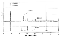
図3は、電池A18及び電池A20の負極のX線回折プロファイルを示す図である。図3から明らかなように、熱処理を400℃で行った電池A20の電極では、ケイ化銅のピークは認められていないが、700℃で熱処理を行った電池A18の電極では、ケイ化銅のピークが認められる。従って、700℃の温度で熱処理することにより、ケイ素粉末に過剰の銅元素が拡散しケイ化銅が析出しているものと思われる。従って、より良好なサイクル特性を得るためには、ケイ化銅が生じないような熱処理条件で焼結することが好ましいことがわかる。
【0071】
図4及び図5は、電池A20に用いた負極の断面を示す走査型電子顕微鏡(SEM)写真である。図4の倍率は1000倍であり、図5の倍率は5000倍である。なお、観察に用いたサンプルは、樹脂で包埋し、スライスしたものである。
【0072】
図4及び図5から明らかなように、ケイ素粉末及び導電性粉末が密に充填した状態で、電解銅箔の表面に接触していることがわかる。
また、電解銅箔表面の凹部にケイ素粉末及びバインダーが密に入り込んでいることがわかる。
【0073】
また、バインダーとして用いたポリフッ化ビニリデン(PVdF)を、400℃及び700℃で熱処理し、熱処理後の赤外線吸収スペクトル(IRスペクトル)を観察した。400℃で熱処理したものにおいては、PVdF及びその分解生成物のピークが検出されたが、700℃で熱処理したものにおいては、PVdFのピークは完全に消失していた。従って、熱処理を400℃で行った電極を用いた電池において優れたサイクル特性が得られた原因として、焼結によるケイ素粒子間及びケイ素粒子と銅箔間の密着性の向上に加え、残存したバインダーによる結着力が働いていることにより、ケイ素粒子間及びケイ素粒子と銅箔間の密着性がさらに高まっていることが考えられる。
【0074】
(実験10)
ここでは、バインダーの種類とサイクル寿命との関係を検討した。
実験1において、バインダーとしてポリビニルピロリドン(PVP)を用い、ケイ素粉末として平均粒径3μmのものを用い、熱処理温度を400℃10時間とする以外は、実験1と同様にして、電池A25を作製した。この電池を用いてサイクル特性の評価を同様にして行い、その結果を表5に示した。表5には、電池A1及び電池A21の結果も併せて示す。なお、各電池のサイクル寿命は、電池A1のサイクル寿命を100とした指数である。
【0075】
【表5】
表5から明らかなように、バインダーとしてフッ素原子を含むPVdFを用いることにより、サイクル特性が良好になることがわかる。
なお、バインダーとしてPVdFを用い、400℃で熱処理した電池A21の電極において、活物質であるケイ素粉末の表面に、ケイ素のフッ化物が存在することが、電子分光分析(XPS)により確かめられている。
【0077】
(実験11)
ここでは、導電性金属粉末の種類とサイクル寿命との関係を検討した。
実験1において、ケイ素粉末として平均粒径3μmのものを用い、導電性金属粉末として表6に示すものを用い、熱処理温度を400℃、30時間としたこと以外は実験1と同様にして電池A26〜A32を作製した。また、導電性金属粉末の代わりにケッチェンブラックを用いて電池B3を作製した。これらの電池を用いて同様に、サイクル特性の評価を行なった。その結果を表6に示す。なお、サイクル寿命は電池A1のサイクル寿命を100とした指数である。表6には、電池A19及び電池A24の結果も併せて示す。
【0078】
【表6】
表6から明らかなように、いずれの導電性金属粉末を用いた電極においても、優れたサイクル特性を示すことがわかる。これは、導電性金属粉末によりケイ素粉末の周りに導電性のネットワークが形成され、高い集電性が得られているためと考えられる。しかし、導電性金属粉末の代わりにケッチェンブラックを用いた場合では、サイクル寿命が短くなっていることがわかる。これは、ケッチェンブラックの密度が小さく、かさ高いため、他の電池と同重量分のバインダー量では、粒子間の結着力を得るには不十分な量であったためと考えられる。
【0080】
(実験12)
ここでは、電極作製工程における圧延の有無とサイクル寿命との関係を検討した。
【0081】
実験1において、電解銅箔の表面上に負極材料のスラリーを塗布した後、圧延しなかったこと以外は、実験1と同様にして、電池A33を作製した。この電池を用いて同様に、サイクル特性の評価を行った。評価結果を表7に示した。表7に示すサイクル寿命は、電池A1のサイクル寿命を100とした指数である。
【0082】
【表7】
表7から明らかなように、電極作製工程において圧延を行うことにより、サイクル特性が良好になっていることがわかる。これは、圧延を行うことにより、活物質粒子がさらに密に充填され、活物質粒子間の接触が良好になるとともに、活物質粒子と導電性金属粉末及び集電体との接触面積が増大し、効果的に焼結が行われるとともに、集電特性が高められたためと考えられる。
【0084】
(実験13)
ここでは、導電性金属粉末であるフレーク状銅粉末を混合せずに、ケイ素粉末のみを用いて電極を作製した。表8に示す銅箔及び平均粒径のケイ素粉末を用い、表8に示す熱処理条件とする以外は、実験1と同様にして、電池C1〜C3及びB4を作製した。これらの電池を用いて、サイクル特性を評価した。その結果を表8に示す。なお、各電池のサイクル寿命は、電池A1のサイクル寿命を100とした指数である。
【0085】
【表8】
表8から明らかなように、平均粒径の小さなケイ素粉末を用い、熱処理温度を400℃とすることにより、サイクル特性を飛躍的に向上できることがわかる。これは、小さな平均粒径のケイ素粉末を用いることにより、焼結が効果的に生じ、ケイ素粒子間及びケイ素粒子と銅箔間の密着性が向上したためと考えられる。
【0087】
また、電池C1と電池B4との比較から明らかなように、表面粗さRaが0.2μm以上の金属箔を用いることにより、サイクル特性が良好になることがわかる。
【0088】
図6は、電池C1及び電池C3の負極のX線回折プロファイルを示す図である。図6から明らかなように、400℃で熱処理した電池C1の電極ではケイ化銅のピークは認められないが、700℃で熱処理した電池C3の電極ではケイ化銅のピークが認められている。従って、導電性金属粉末を混合せずにケイ素粉末のみを用いた場合においても、X線回折でケイ化銅の析出が検出されないような熱処理温度で焼結することが好ましいことがわかる。
【0089】
(実験14)
ここでは、導電性金属粉末であるフレーク状銅粉末を混合せずに、ケイ素粉末のみを用いた電極におけるバインダーの種類とサイクル寿命の関係について検討した。実験1において、平均粒径3μmのケイ素粉末を用い、フレーク状銅粉末を混合せず、熱処理条件及びバインダーを表9に示すものとしたこと以外は実験1と同様にして電池D1〜D5を作製した。なお、バインダーとしてポリイミドを用いる場合は、ケイ素粉末90重量部を、ポリアミド酸10重量部を含む18重量%のN−メチルピロリドン溶液に混合したものを負極合剤スラリーとし、塗布後、熱処理し、電極の作製を行なった。電極における400℃での熱処理後のポリイミドのイミド化率は100%であった。また、バインダーとして、スチレンブタジエンゴム(SBR)及びポリテトラフルオロエチレン(PTFE)を用いる場合は、増粘剤としてのカルボキシメチルセルロース(CMC)1重量部を含む3重量%の水溶液と、スチレンブタジエンゴム(SBR)10重量部を含む48重量%の水性分散液またはポリテトラフルオロエチレン(PTFE)10重量部を含む60重量%の水性分散液との混合物にケイ素粉末90重量部を混合したものを負極合剤スラリーとして用い、電極の作製を行なった。また、バインダーとしてポリビニルピロリドン(PVP)を用いる場合は、ケイ素粉末90重量部を、ポリビニルピロリドン(PVP)10重量部を含む8重量%のN−メチルピロリドン溶液に混合したものを負極合剤スラリーとして用い、電極の作製を行った。
【0090】
これらの電極を用いて実験1と同様にして電池D1〜D5を作製し、サイクル特性の評価を行なった。その結果を表9に示す。なお、各電池のサイクル寿命は、電池A1のサイクル寿命を100とした指数である。
【0091】
バインダーの熱分解開始温度は、バインダーの熱重量測定において、重量が減少し始めた温度とした。
【0092】
【表9】
表9からわかるように、分解開始温度の高いバインダーを用いた方が優れたサイクル特性を示すことがわかる。これは、熱処理後もバインダーが完全に分解せずに残存していることにより、焼結による活物質と集電体間及び活物質粒子間の密着性の向上に加え、バインダーによる結着力も加わり、さらに密着性の高い電極が得られたためと考えられる。
【0094】
(実験15)
ここでは、導電性金属粉末であるフレーク状銅粉末を混合せずに、ケイ素粉末のみを用いた電極におけるケイ素粉末粒径とサイクル寿命の関係について検討した。実験14でのバインダーとしてポリイミドを用いた場合において、熱処理条件及びケイ素粉末の平均粒径を表10に示すものとしたこと以外は実験1と同様にして電池D6〜D10を作製した。これらの電池を用いて実験1と同様に、サイクル特性の評価を行なった。その結果を表10に示す。各電池のサイクル寿命は、電池A1のサイクル寿命を100とした指数である。なお、表10には電池A1及び電池C2の結果も併せて示す。
【0095】
【表10】
表10から明らかなように、平均粒径10μm以下のケイ素粉末を用いた方が優れたサイクル特性を示していることがわかる。
【0097】
(実験16)
ここでは、導電性金属粉末であるフレーク状銅粉末を混合せずに、ケイ素粉末のみを用いた電極におけるバインダー量とサイクル特性の関係について検討した。実験1において、平均粒径3μmのケイ素粉末を用いフレーク状銅粉末を混合せず、熱処理条件及びバインダーを表11に示すものとしたこと以外は実験1と同様にして電池D11〜D16を作製した。なお、バインダーとして、ポリイミドを用いた場合は、実験14でのバインダーとしてポリイミドを用いた場合と同様にして電極を作製した。これらの電池を用いて実験1と同様に、サイクル特性の評価を行なった。その結果を表11に示す。各電池のサイクル寿命は、電池A1のサイクル寿命を100とした指数である。なお、電池A1、D1及びD2の結果も併せて表11に示す。
【0098】
【表11】
表11から明らかなように、バインダー量が5.3重量%以上、好ましくは10重量%以上のものが優れたサイクル特性を示していることがわかる。これは、Li吸蔵放出時の活物質粒子の大きな体積変化の際にも活物質粒子と集電体間及び活物質粒子間の密着性を保つのに、充分な量のバインダーが存在するためと考えられる。
【0100】
【発明の効果】
本発明によれば、充放電サイクル特性に優れたリチウム二次電池用負極及びリチウム二次電池とすることができる。
【図面の簡単な説明】
【図1】本発明に従う実施例において作製したリチウム二次電池を示す模式的断面図。
【図2】本発明に従う一例のリチウム二次電池用負極を示す模式的断面図。
【図3】実施例において作製した電池A18及びA20の負極のX線回折プロファイルを示す図。
【図4】実施例において作製した電池A20の負極の断面の走査型電子顕微鏡写真を示す図(倍率1000倍)。
【図5】実施例において作製した電池A20の負極の断面の走査型電子顕微鏡写真を示す図(倍率5000倍)。
【図6】実施例において作製した電池C1及びC3の負極のX線回折プロファイルを示す図。
【符号の説明】
1…正極
2…負極
3…セパレーター
4…正極缶
5…負極缶
6…正極集電体
7…負極集電体
8…絶縁パッキング
11…導電性金属箔
12…活物質粒子
12a,12b…拡散領域
13…導電性金属粉末[0001]
BACKGROUND OF THE INVENTION
The present invention relates to an electrode for a lithium secondary battery, a method for producing the same, and a lithium secondary battery.
[0002]
[Prior art]
When lithium metal is used for the negative electrode of a lithium secondary battery, a high charge / discharge capacity can be obtained. However, since lithium metal is deposited in a dendritic form on the negative electrode during charging, there is a problem that an internal short circuit is likely to occur. have.
[0003]
As a material that does not cause such a problem and can be expected to have a high charge / discharge capacity, it is conceivable to use a metal that forms an alloy with lithium, such as Si, Sn, and Al, as the negative electrode active material. However, when such an alloying metal is used as an active material, a high capacity can be expected, but the volume of the active material changes greatly due to repeated charge and discharge, so that the active material is pulverized and the current collector There is a problem of peeling.
[0004]
In JP-A-11-339777, a slurry containing silicon powder as an active material is applied on a current collector, and then fired in a non-oxidizing atmosphere, whereby a current between the current collector and the active material is obtained. It has been proposed to reduce the contact resistance.
[0005]
Also, in Japanese Patent Publication No. 11-2948205, a negative electrode of a lithium secondary battery is obtained by applying silicon or a composite of silicon and carbon on a conductive metal substrate and sintering it in a non-oxidizing atmosphere. Has been proposed.
[0006]
Japanese Laid-Open Patent Publication No. 2000-12089 proposes using a composite of copper silicide or silicon and conductive carbon or conductive metal sintered with a conductive metal foil. Japanese Patent Application Laid-Open No. 2000-12088 proposes to use a current collector having an average roughness of 0.03 μm or more adhered to the active material with a binder.
[0007]
[Problems to be solved by the invention]
However, even with the above conventional method, there is a problem that sufficiently good charge / discharge cycle characteristics cannot be obtained and a practical negative electrode for a lithium secondary battery cannot be obtained.
[0008]
The objective of this invention is related with the lithium secondary battery using the electrode for lithium secondary batteries which can obtain high charging / discharging capacity | capacitance, and was excellent in charging / discharging characteristics, and this.
[0009]
[Means for Solving the Problems]
The negative electrode for a lithium secondary battery according to the first aspect of the present invention uses a conductive metal foil having a surface roughness Ra of 0.2 μm or more as a current collector, and is electrically conductive with active material particles containing silicon and / or a silicon alloy. It is characterized in that it is obtained by sintering a layer of a mixture of conductive metal powder on the surface of the current collector in a non-oxidizing atmosphere.
[0010]
The negative electrode for a lithium secondary battery according to the second aspect of the present invention is a layer of active material particles containing a conductive metal foil having a surface roughness Ra of 0.2 μm or more as a current collector and containing silicon and / or a silicon alloy. Is obtained by sintering in a non-oxidizing atmosphere on the surface of the current collector.
[0011]
The method for producing a negative electrode for a lithium secondary battery according to the third aspect of the present invention includes an active material particle containing silicon and / or a silicon alloy on the surface of a conductive metal foil having a surface roughness Ra of 0.2 μm or more. And a step of forming a layer of the mixture of the conductive metal powder and a step of sintering in a non-oxidizing atmosphere in a state where the layer of the mixture is disposed on the surface of the conductive metal foil. .
[0012]
The method for producing a negative electrode for a lithium secondary battery according to the fourth aspect of the present invention includes an active material particle containing silicon and / or a silicon alloy on the surface of a conductive metal foil having a surface roughness Ra of 0.2 μm or more. And a step of sintering in a non-oxidizing atmosphere with the active material particle layer disposed on the surface of the conductive metal foil.
[0013]
In the lithium secondary battery electrode according to the fifth aspect of the present invention, a layer of active material particles made of a material alloying with lithium is provided on a current collector, and the active material particles are in the active material particle layer. It is characterized in that components that are bonded to each other by sintering and that do not alloy with lithium are diffused in the active material particles.
[0014]
The lithium secondary battery of the present invention is the negative electrode of the first or second aspect of the present invention, the negative electrode manufactured from the method of the third or fourth aspect of the present invention, or the fifth aspect of the present invention. It is characterized by comprising a negative electrode made of an electrode, a positive electrode containing a positive electrode active material, and a non-aqueous electrolyte.
[0015]
Hereinafter, matters common to the first to fifth aspects of the present invention will be described as “the present invention”.
In the present invention, a conductive metal foil having a surface roughness Ra of 0.2 μm or more is preferably used as the current collector. The value of the surface roughness Ra is a value before sintering. By using a conductive metal foil having such a surface roughness Ra as a current collector, the contact area between the mixture of active material particles and conductive metal powder and the surface of the metal foil is increased. Sintering occurs effectively, and adhesion between the active material particles, the conductive metal powder, and the current collector is greatly improved. For this reason, the large volume expansion | swelling and shrinkage | contraction of an active material which are produced at the time of occlusion / release of lithium in charging / discharging reaction, and peeling from the collector of the active material by micronization are suppressed. In addition, even when only active material particles are used without mixing conductive metal powder, the contact area with the current collector can be increased, and the adhesion between the active material particles and the current collector is improved. be able to.
[0016]
The upper limit of the surface roughness Ra of the conductive metal foil is not particularly limited. However, as described later, it is preferable that the thickness of the conductive metal foil is in the range of 10 to 100 μm. The upper limit of the surface roughness Ra is 10 μm or less.
[0017]
Moreover, it is preferable that the surface roughness Ra and the average interval S between the local peaks have a relationship of 100Ra ≧ S. The surface roughness Ra and the average interval S between the local peaks are defined in Japanese Industrial Standard (JIS B 0601-1994), and can be measured, for example, with a surface roughness meter.
[0018]
In the present invention, when the conductive metal powder is sintered in a state of being mixed with the active material particles, a strong conductive network is formed around the active material particles by the conductive metal powder. For this reason, even if pulverization occurs, the current collecting property is maintained, and the increase in contact resistance can be suppressed.
[0019]
Examples of the conductive metal foil used as the current collector in the present invention include those made of metals such as copper, nickel, iron, titanium, cobalt, and alloys made of combinations thereof. In particular, those containing a metal element that easily diffuses into the active material particles are preferable. From such a viewpoint, a copper foil or a copper alloy foil is preferable. Copper element is easily diffused into the active material particles by heat treatment, and it can be expected that the bonding with the active material particles during sintering is improved. Examples of the copper foil having a surface roughness Ra of 0.2 μm or more include electrolytic copper foil and electrolytic copper alloy foil. The electrolytic copper foil and the electrolytic copper alloy foil are obtained by depositing copper or a copper alloy on the surface of the copper foil by an electrolytic method. Moreover, the other metal foil which formed the copper or copper alloy by the electrolytic method on the surface may be sufficient. As such a thing, what deposited copper or a copper alloy on the surface of nickel foil by the electrolytic method can be mentioned.
[0020]
In the present invention, as the conductive metal powder mixed with the active material particles, the same material as the conductive metal foil can be preferably used. Specifically, it is an alloy or a mixture made of a metal such as copper, nickel, iron, titanium, cobalt, or a combination thereof. In particular, copper powder is preferably used as the conductive metal powder. By sintering the mixture of the active material particles and the conductive metal powder on the surface of the current collector, the metal component in the conductive metal foil and / or the conductive metal powder diffuses into the active material particles, and the active material It is considered that this metal component is unevenly distributed around the particle. By using a metal component that does not alloy with lithium, such as copper, as the metal component, the expansion and contraction of the volume during the charge / discharge reaction is suppressed at the location where this metal component is unevenly distributed. Peeling of the active material and pulverization of the current collector material are suppressed, and the charge / discharge cycle characteristics can be improved.
[0021]
Examples of the active material particles used in the present invention include silicon and / or silicon alloy powder. Examples of silicon alloys include solid solutions of silicon and one or more other elements, intermetallic compounds of silicon and one or more other elements, and eutectic alloys of silicon and one or more other elements. It is done. Examples of the method for producing the alloy include an arc melting method, a liquid quenching method, a mechanical alloying method, a sputtering method, a chemical vapor deposition method, and a firing method. In particular, examples of the liquid quenching method include a single roll quenching method, a twin roll quenching method, and various atomizing methods such as a gas atomizing method, a water atomizing method, and a disk atomizing method.
[0022]
The active material particles used in the present invention may be those obtained by coating the surface of silicon and / or silicon alloy particles with a metal or the like. Examples of the coating method include an electroless plating method, an electrolytic plating method, a chemical reduction method, a vapor deposition method, a sputtering method, and a chemical vapor deposition method. The metal covering the particle surface is preferably the same metal as the conductive metal foil or conductive metal powder. By coating the same metal as the conductive metal foil and the conductive metal powder, the bondability between the current collector and the conductive metal powder during sintering is greatly improved, and further excellent charge / discharge cycle characteristics are obtained. be able to.
[0023]
As the active material particles used in the present invention, particles made of a material alloyed with lithium may be used. Examples of materials for alloying lithium include germanium, tin, lead, zinc, magnesium, sodium, aluminum, gallium, indium, and alloys thereof in addition to the above silicon and silicon alloys.
[0024]
The average particle size of the active material particles used in the present invention is not particularly limited, but is preferably 100 μm or less, more preferably 50 μm or less, and most preferably 10 μm or less in order to produce effective sintering. . The smaller the average particle diameter of the active material particles, the better the cycle characteristics. The average particle size of the conductive metal powder used in the present invention is not particularly limited, but is preferably 100 μm or less, more preferably 50 μm or less, and further preferably 10 μm or less.
[0025]
In the present invention, the mixing ratio of the conductive metal powder is preferably in the range of 0.05 to 50 with respect to the
[0026]
However, when the average particle diameter of the active material particles is small, good charge / discharge cycle characteristics may be obtained even when the conductive metal powder is not mixed, that is, only the active material particles.
[0027]
In the present invention, the thickness of the conductive metal foil is not particularly limited, but is preferably in the range of 10 μm to 100 μm. Further, the thickness of the sintered body composed of the active material particle and conductive metal powder mixture layer or the active material particle layer on the conductive metal foil is not particularly limited, but is preferably 1000 μm or less, Preferably they are 10 micrometers-100 micrometers.
[0028]
Sintering in a non-oxidizing atmosphere in the present invention is performed, for example, in a nitrogen atmosphere or an inert gas atmosphere such as argon. You may carry out in reducing environment, such as hydrogen atmosphere. The temperature of the heat treatment at the time of sintering is preferably a temperature not higher than the melting point of the conductive metal foil, the conductive metal powder, and the active material particles. For example, when copper is used as the conductive metal foil and the conductive metal powder, the melting point is preferably 1083 ° C. or lower, more preferably 200 to 500 ° C., further preferably 300 to 450 ° C. is there. As a method for sintering, a discharge plasma sintering method or a hot press method may be used.
[0029]
When powder containing silicon and / or silicon alloy is used as the active material particles and copper element is diffused in the active material particles, if the temperature of the heat treatment during sintering is increased, a large amount of copper element is contained in the active material particles. In some cases, copper silicide which is an intermetallic compound of silicon and copper is formed. When copper silicide is formed, the charge / discharge cycle characteristics tend to be deteriorated. Therefore, it is preferable to sinter under conditions such that precipitation of copper silicide is not detected by X-ray diffraction.
[0030]
From the above viewpoint, it is preferable to sinter in the above temperature range.
In the present invention, a slurry containing active material particles, conductive metal powder and a binder, or a slurry containing active material particles and a binder is applied, and the mixture is placed on the conductive metal foil as a current collector. A layer or a layer of active material particles can be formed. It is preferable that the binder remains without being completely decomposed after the heat treatment for sintering. Since the binder remains without being decomposed after the heat treatment, in addition to the improvement of the adhesion between the active material particles and the current collector due to the sintering and the improvement of the adhesion between the active material particles, the binder is bonded. Adhesive force is also added, and adhesion can be further enhanced. Therefore, pulverization of the active material particles and separation of the active material particles from the current collector are suppressed, and more favorable charge / discharge cycle characteristics can be obtained.
[0031]
As the binder in the present invention, polyimide is preferably used. Polyimide can be obtained by heat-treating polyamic acid, for example. By this heat treatment, the polyamic acid undergoes dehydration condensation to produce polyimide. In the present invention, a polyimide having an imidization ratio of 80% or more is preferable. When the imidation ratio of the polyimide is less than 80%, the adhesion between the active material particles and the current collector may not be good. Here, the imidization rate is the mol% of the produced polyimide with respect to the polyimide precursor. Those having an imidization rate of 80 or more can be obtained, for example, by heat-treating a polyamic acid NMP (N-methylpyrrolidone) solution at a temperature of 100 ° C. to 400 ° C. for 1 hour or more. For example, when heat treatment is performed at 350 ° C., the imidation rate is about 80% after about 1 hour of heat treatment, and the imidation rate is about 100% after about 3 hours. In the present invention, it is preferable that the binder remains without being completely decomposed even after the heat treatment for sintering. Therefore, when polyimide is used as the binder, the polyimide is not completely decomposed at 600 ° C. or lower. It is preferable to sinter at this temperature.
[0032]
A binder containing a fluorine atom can also be preferably used as the binder. As the binder containing a fluorine atom, polyvinylidene fluoride and polytetrafluoroethylene are particularly preferable. By using polyvinylidene fluoride or polytetrafluoroethylene as a binder and performing a heat treatment for sintering at a temperature at which the binder does not completely decompose, better charge / discharge cycle characteristics can be obtained.
[0033]
From the above viewpoint, the heat treatment temperature during sintering is preferably 200 to 500 ° C., more preferably 300 to 450 ° C. as described above.
In the present invention, after forming a layer of a mixture of active material particles and a conductive metal powder or a layer of active material particles on a conductive metal foil as a current collector, before sintering, The layer is preferably rolled together with the conductive metal foil. By such rolling, the packing density in the layer of the mixture or the layer of active material particles can be increased, and the adhesion between the particles and the adhesion between the particles and the current collector can be improved. Cycle characteristics can be obtained.
[0034]
Moreover, in this invention, it is preferable that the active material particle and / or the binder have entered into the recessed part of the surface of electroconductive metal foil. When the active material particles and / or the binder enter the recesses on the surface of the conductive metal foil, the adhesion between the mixture layer or the layer of active material particles and the current collector can be further improved.
[0035]
The lithium secondary battery of the present invention comprises the negative electrode of the present invention or the negative electrode comprising the electrode of the present invention or the negative electrode produced by the production method of the present invention, a positive electrode containing a positive electrode active material, and a non-aqueous electrolyte. It is characterized by becoming.
[0036]
The solvent of the electrolyte used in the lithium secondary battery of the present invention is not particularly limited, but a cyclic carbonate such as ethylene carbonate, propylene carbonate, and butylene carbonate, and a chain such as dimethyl carbonate, methyl ethyl carbonate, and diethyl carbonate. A mixed solvent with carbonate is exemplified. Further, mixed solvents of the cyclic carbonate and ether solvents such as 1,2-dimethoxyethane and 1,2-diethoxyethane are also exemplified. Moreover, as a solute of the electrolyte, LiPF 6 , LiBF Four , LiCF Three SO Three , LiN (CF Three SO 2 ) 2 , LiN (C 2 F Five SO 2 ) 2 , LiN (CF Three SO 2 ) (C Four F 9 SO 2 ), LiC (CF Three SO 2 ) Three , LiC (C 2 F Five SO 2 ) Three And mixtures thereof. Further, as the electrolyte, a gel polymer electrolyte in which a polymer electrolyte such as polyethylene oxide or polyacrylonitrile is impregnated with an electrolytic solution, LiI, Li Three An inorganic solid electrolyte such as N is exemplified. The electrolyte of the lithium secondary battery of the present invention is not limited as long as the lithium compound as a solvent that develops ionic conductivity and the solvent that dissolves and retains the lithium compound do not decompose at the time of battery charging, discharging, or storage. Can be used.
[0037]
As the positive electrode active material of the lithium secondary battery of the present invention, LiCoO 2 , LiNiO 2 , LiMn 2 O Four LiMnO 2 LiCo 0.5 Ni 0.5 O 2 , LiNi 0.7 Co 0.2 Mn 0.1 O 2 Lithium-containing transition metal oxides such as MnO 2 Examples thereof include metal oxides not containing lithium. In addition, any substance that electrochemically inserts and desorbs lithium can be used without limitation.
[0038]
FIG. 2 is a schematic cross-sectional view showing an example of the negative electrode for a lithium secondary battery of the present invention. On the
[0039]
DETAILED DESCRIPTION OF THE INVENTION
Hereinafter, the present invention will be described in more detail based on examples. However, the present invention is not limited to the following examples, and can be implemented with appropriate modifications within a range not changing the gist thereof. Is.
[0040]
(Experiment 1)
(Production of negative electrode)
The weight ratio of the flaky copper powder having an average particle diameter of 10 μm as the conductive metal powder and the silicon powder having an average particle diameter of 50 μm as the active material particles is 4: 1 (= 1: 0.25). Weighed and dry-mixed in a mortar. 90 parts by weight of this mixture was mixed with an 8% by weight N-methylpyrrolidone solution containing 10 parts by weight of polyvinylidene fluoride as a binder to obtain a negative electrode mixture slurry.
[0041]
This negative electrode mixture slurry was applied to one surface of an electrolytic copper foil (thickness 15 μm) having a surface roughness Ra of 0.5 μm as a current collector, dried, and then rolled. The obtained product was cut out into a disk shape with a diameter of 20 mm, heat-treated at 700 ° C. for 10 hours in an argon atmosphere, and sintered to obtain a negative electrode. The thickness of the sintered body (not including the current collector) was 50 μm.
[0042]
[Production of positive electrode]
As a starting material, Li 2 CO Three And CoCO Three Are weighed so that the atomic ratio of Li: Co is 1: 1, mixed in a mortar, pressed with a metal mold having a diameter of 17 mm, and press-molded. LiCoO fired for a long time 2 A fired body was obtained. This was pulverized in a mortar to prepare an average particle size of 20 μm.
[0043]
Obtained
This positive electrode mixture slurry was applied onto an aluminum foil as a current collector, dried and then rolled. The obtained product was cut out into a disk shape having a diameter of 20 mm to obtain a positive electrode.
[0044]
(Preparation of electrolyte)
As an electrolytic solution, an equal volume mixed solvent of ethylene carbonate and diethylene carbonate, LiPF 6 Was prepared by dissolving 1 mol / liter.
[0045]
[Production of battery]
Using the positive electrode, the negative electrode, and the electrolytic solution, a flat lithium secondary battery A1 was produced.
[0046]
FIG. 1 is a schematic cross-sectional view of a manufactured lithium secondary battery, and includes
[0047]
The
[0048]
(Experiment 2)
Silicon and nickel or copper are mixed so as to have an atomic ratio of 9: 1. 9 Ni alloy and Si 9 A Cu alloy was produced. These alloys were pulverized with a mortar to an average particle size of 50 μm. In
[0049]
(Experiment 3)
The surface of silicon powder having an average particle size of 50 μm was coated with nickel by an electroless plating method. When what was obtained was confirmed by atomic absorption spectrometry (ICP), the coating amount of silicon powder with nickel was 0.5% by weight based on the whole.
In
[0050]
(Experiment 4)
Copper was deposited on the surfaces of the nickel foil and the stainless steel foil by an electrolytic method to prepare a copper-coated nickel foil (thickness 15 μm) and a copper-coated stainless steel foil (thickness 15 μm). These surface roughnesses Ra were all 0.5 μm.
[0051]
In
[0052]
Further, batteries A7 and A8 were produced in the same manner as in
[0053]
(Experiment 5)
In
[0054]
In addition, an experiment was conducted except that a flaky copper powder used in
[0055]
(Experiment 6)
In
In
[0056]
[Evaluation of charge / discharge cycle characteristics]
Charge / discharge cycle characteristics of the batteries A1 to A12 and B1 were evaluated. Each battery was charged to 4.2 V at a current value of 1 mA at 25 ° C., and then discharged to 2.7 V at a current value of 1 mA. The number of cycles to reach 80% of the discharge capacity at the first cycle was measured and defined as the cycle life. The results are shown in Table 1. The cycle life of each battery is an index with the cycle life of the battery A1 as 100.
[0057]
[Table 1]
As is apparent from Table 1, the batteries A1 to A12 using the metal foil having a surface roughness Ra of 0.2 μm or more are compared with the battery B1 using the metal foil having a surface roughness Ra of 0.1 μm. It can be seen that the cycle life is long. This is because, by using a metal foil having a surface roughness Ra of 0.2 μm or more, active material particles, conductive metal powder, and conductive metal foil are effectively sintered, and the current collector of the active material particles This is thought to be due to a lot of improvement in the adhesion to the surface.
[0059]
(Experiment 7)
Here, the influence of sintering on cycle characteristics was examined.
In
[0060]
[Table 2]
As is apparent from Table 2, the battery A1 subjected to the heat treatment shows much better cycle characteristics than the battery B2 not subjected to the heat treatment. This is because heat treatment improves the adhesion between the active material particles, the conductive metal powder, and the conductive metal foil, and the metal components from the conductive metal foil and the conductive metal powder diffuse into the active material particles. However, it is considered that this diffusion region network was formed and the current collecting property was improved.
[0062]
(Experiment 8)
Here, the relationship between the mixing amount of the conductive metal powder and the cycle characteristics was examined.
In
[0063]
For these batteries, the cycle characteristics were evaluated in the same manner as described above. The results are shown in Table 3. The cycle life of each battery is an index with the cycle life of the battery A1 as 100.
[0064]
[Table 3]
As is apparent from Table 3, the batteries A1 and A13 to A15 mixed with the flaky copper powder show far better cycle life than the battery A16 not mixed with the flaky copper powder. . This is because, by mixing copper powder, the adhesion of silicon powder, which is an active material particle, is improved, and a strong conductive network is formed around the silicon powder. Is considered to have improved.
[0066]
(Experiment 9)
Here, the relationship between the heat treatment temperature, the average particle diameter of the silicon powder, and the average particle diameter of the conductive metal powder and the cycle life was examined.
[0067]
In
[0068]
[Table 4]
As is apparent from Table 4, it is understood that the cycle characteristics are remarkably improved by setting the heat treatment temperature in the range of 200 ° C to 500 ° C. It can be seen that the heat treatment temperature is particularly preferably about 400 ° C. Further, as is apparent from the comparison between the battery A1 and the battery A18 and the battery A17 and the battery A20, the cycle characteristics are remarkably improved by reducing the average particle size of the silicon powder from 50 μm to 3 μm.
[0070]
FIG. 3 is a diagram showing X-ray diffraction profiles of the negative electrodes of the battery A18 and the battery A20. As apparent from FIG. 3, the peak of copper silicide was not observed in the electrode of the battery A20 that was heat-treated at 400 ° C., but the electrode of battery A18 that was heat-treated at 700 ° C. A peak is observed. Therefore, it is considered that, by heat treatment at a temperature of 700 ° C., excess copper element diffuses into the silicon powder and copper silicide is deposited. Therefore, it can be seen that in order to obtain better cycle characteristics, it is preferable to sinter under heat treatment conditions that do not produce copper silicide.
[0071]
4 and 5 are scanning electron microscope (SEM) photographs showing a cross section of the negative electrode used in the battery A20. The magnification of FIG. 4 is 1000 times, and the magnification of FIG. 5 is 5000 times. In addition, the sample used for observation was embedded and sliced with resin.
[0072]
As is apparent from FIGS. 4 and 5, it can be seen that the silicon powder and the conductive powder are in close contact with the surface of the electrolytic copper foil in a state of being densely packed.
Moreover, it turns out that the silicon powder and the binder have penetrated densely in the recessed part of the electrolytic copper foil surface.
[0073]
In addition, polyvinylidene fluoride (PVdF) used as a binder was heat-treated at 400 ° C. and 700 ° C., and an infrared absorption spectrum (IR spectrum) after the heat treatment was observed. In the case of heat treatment at 400 ° C., the peak of PVdF and its decomposition product was detected, but in the case of heat treatment at 700 ° C., the peak of PVdF disappeared completely. Therefore, the reason why excellent cycle characteristics were obtained in a battery using an electrode that was heat-treated at 400 ° C. was that in addition to improving adhesion between silicon particles and between silicon particles and copper foil by sintering, the remaining binder It is considered that the adhesion between the silicon particles and between the silicon particles and the copper foil is further enhanced by the action of the binding force due to.
[0074]
(Experiment 10)
Here, the relationship between the binder type and the cycle life was examined.
A battery A25 was produced in the same manner as in
[0075]
[Table 5]
As can be seen from Table 5, the cycle characteristics are improved by using PVdF containing fluorine atoms as the binder.
In addition, in the electrode of battery A21 heat treated at 400 ° C. using PVdF as a binder, the presence of silicon fluoride on the surface of the silicon powder as the active material has been confirmed by electron spectroscopic analysis (XPS). .
[0077]
(Experiment 11)
Here, the relationship between the type of conductive metal powder and the cycle life was examined.
In
[0078]
[Table 6]
As is apparent from Table 6, it can be seen that the electrode using any conductive metal powder exhibits excellent cycle characteristics. This is presumably because a conductive network is formed around the silicon powder by the conductive metal powder, and a high current collecting property is obtained. However, when ketjen black is used instead of the conductive metal powder, it can be seen that the cycle life is shortened. This is thought to be because the density of ketjen black is small and bulky, so that the amount of binder equivalent to that of other batteries is insufficient to obtain a binding force between particles.
[0080]
(Experiment 12)
Here, the relationship between the presence or absence of rolling in the electrode manufacturing process and the cycle life was examined.
[0081]
In
[0082]
[Table 7]
As is apparent from Table 7, it can be seen that the cycle characteristics are improved by rolling in the electrode manufacturing process. By rolling, the active material particles are more densely packed, the contact between the active material particles is improved, and the contact area between the active material particles, the conductive metal powder, and the current collector is increased. This is probably because the sintering was effectively performed and the current collecting characteristics were enhanced.
[0084]
(Experiment 13)
Here, an electrode was produced using only silicon powder without mixing the flaky copper powder, which is a conductive metal powder. Batteries C1 to C3 and B4 were produced in the same manner as in
[0085]
[Table 8]
As is apparent from Table 8, it is understood that the cycle characteristics can be drastically improved by using silicon powder having a small average particle diameter and setting the heat treatment temperature to 400 ° C. This is presumably because the use of silicon powder having a small average particle diameter effectively produced sintering and improved the adhesion between the silicon particles and between the silicon particles and the copper foil.
[0087]
Further, as is clear from the comparison between the battery C1 and the battery B4, it is understood that the cycle characteristics are improved by using a metal foil having a surface roughness Ra of 0.2 μm or more.
[0088]
FIG. 6 is a diagram showing X-ray diffraction profiles of the negative electrodes of the battery C1 and the battery C3. As is clear from FIG. 6, the peak of copper silicide is not observed in the electrode of battery C1 heat-treated at 400 ° C., but the peak of copper silicide is recognized in the electrode of battery C3 heat-treated at 700 ° C. Therefore, it can be seen that it is preferable to sinter at a heat treatment temperature at which the precipitation of copper silicide is not detected by X-ray diffraction even when only the silicon powder is used without mixing the conductive metal powder.
[0089]
(Experiment 14)
Here, the relationship between the type of binder and the cycle life in an electrode using only silicon powder was examined without mixing the flaky copper powder, which is a conductive metal powder. In
[0090]
Using these electrodes, batteries D1 to D5 were produced in the same manner as in
[0091]
The thermal decomposition start temperature of the binder was a temperature at which the weight began to decrease in thermogravimetric measurement of the binder.
[0092]
[Table 9]
As can be seen from Table 9, it can be seen that the use of a binder having a higher decomposition start temperature exhibits superior cycle characteristics. This is because, after the heat treatment, the binder remains without being completely decomposed, and in addition to improving the adhesion between the active material and the current collector and between the active material particles by sintering, the binding force by the binder is also added. This is probably because an electrode having higher adhesion was obtained.
[0094]
(Experiment 15)
Here, the relationship between the silicon powder particle size and the cycle life in an electrode using only silicon powder was examined without mixing the flaky copper powder, which is a conductive metal powder. Batteries D6 to D10 were produced in the same manner as in
[0095]
[Table 10]
As is apparent from Table 10, it can be seen that the use of silicon powder having an average particle size of 10 μm or less shows excellent cycle characteristics.
[0097]
(Experiment 16)
Here, the relationship between the binder amount and the cycle characteristics in an electrode using only silicon powder was examined without mixing the flaky copper powder, which is a conductive metal powder. In
[0098]
[Table 11]
As is apparent from Table 11, it can be seen that a binder amount of 5.3% by weight or more, preferably 10% by weight or more shows excellent cycle characteristics. This is because there is a sufficient amount of binder to maintain the adhesion between the active material particles and the current collector and between the active material particles even when the volume of the active material particles changes greatly during Li storage and release. Conceivable.
[0100]
【The invention's effect】
ADVANTAGE OF THE INVENTION According to this invention, it can be set as the negative electrode for lithium secondary batteries and the lithium secondary battery excellent in charging / discharging cycling characteristics.
[Brief description of the drawings]
FIG. 1 is a schematic cross-sectional view showing a lithium secondary battery manufactured in an example according to the present invention.
FIG. 2 is a schematic cross-sectional view showing an example negative electrode for a lithium secondary battery according to the present invention.
FIG. 3 is a diagram showing X-ray diffraction profiles of negative electrodes of batteries A18 and A20 manufactured in Examples.
FIG. 4 is a view showing a scanning electron micrograph of a cross section of a negative electrode of a battery A20 produced in Example (magnification 1000 times).
FIG. 5 is a view showing a scanning electron micrograph of a cross section of a negative electrode of a battery A20 produced in Example (5000 times magnification).
FIG. 6 is a diagram showing X-ray diffraction profiles of negative electrodes of batteries C1 and C3 manufactured in Examples.
[Explanation of symbols]
1 ... Positive electrode
2 ... Negative electrode
3 ... Separator
4 ... Positive electrode can
5 ... Negative electrode can
6 ... Positive electrode current collector
7 ... Negative electrode current collector
8 ... Insulation packing
11 ... Conductive metal foil
12 ... Active material particles
12a, 12b ... diffusion region
13 ... Conductive metal powder
Claims (38)
前記混合物の層を前記導電性金属箔の表面上に配置した状態で非酸化性雰囲気下に前記バインダーが熱処理後に残存する温度で焼結する工程とを備えることを特徴とするリチウム二次電池用負極の製造方法。Forming a layer of a mixture of active material particles containing silicon and / or a silicon alloy, a conductive metal powder and a binder on the surface of a conductive metal foil having a surface roughness Ra of 0.2 μm or more and 10 μm or less ; ,
A step of sintering the binder at a temperature at which the binder remains after heat treatment in a non-oxidizing atmosphere with the layer of the mixture disposed on the surface of the conductive metal foil. Manufacturing method of negative electrode.
前記活物質粒子とバインダーの層を前記導電性金属箔の表面上に配置した状態で非酸化性雰囲気下に前記バインダーが熱処理後に残存する温度で焼結する工程とを備えることを特徴とするリチウム二次電池用負極の製造方法。Forming a layer of active material particles containing silicon and / or a silicon alloy and a binder on the surface of the conductive metal foil having a surface roughness Ra of 0.2 μm or more and 10 μm or less ;
And a step of sintering the binder at a temperature at which the binder remains after heat treatment in a non-oxidizing atmosphere with the active material particle and binder layers disposed on the surface of the conductive metal foil. A method for producing a negative electrode for a secondary battery.
Priority Applications (10)
| Application Number | Priority Date | Filing Date | Title |
|---|---|---|---|
| JP2001254261A JP4212263B2 (en) | 2000-09-01 | 2001-08-24 | Negative electrode for lithium secondary battery and method for producing the same |
| CNB018148255A CN1280930C (en) | 2000-09-01 | 2001-08-31 | Negative electrode for lithium secondary cell and method for producing the same |
| PCT/JP2001/007519 WO2002021616A1 (en) | 2000-09-01 | 2001-08-31 | Negative electrode for lithium secondary cell and method for producing the same |
| EP10004070A EP2219249A1 (en) | 2000-09-01 | 2001-08-31 | Electrode for rechargeable lithium battery |
| CA2420104A CA2420104C (en) | 2000-09-01 | 2001-08-31 | Negative electrode for lithium secondary cell and method for producing the same |
| AU2001282569A AU2001282569A1 (en) | 2000-09-01 | 2001-08-31 | Negative electrode for lithium secondary cell and method for producing the same |
| KR10-2003-7003069A KR100501142B1 (en) | 2000-09-01 | 2001-08-31 | Negative electrode for lithium secondary cell and method for producing the same |
| EP01961241A EP1335438A4 (en) | 2000-09-01 | 2001-08-31 | Negative electrode for lithium secondary cell and method for producing the same |
| US10/363,039 US20040043294A1 (en) | 2000-09-01 | 2002-08-31 | Negative electrode for lithium secondary cell and method for producing the same |
| HK04101959A HK1059149A1 (en) | 2000-09-01 | 2004-03-17 | Negative electrode for rechargeable lithium battery and method for fabrication thereof |
Applications Claiming Priority (5)
| Application Number | Priority Date | Filing Date | Title |
|---|---|---|---|
| JP2000265901 | 2000-09-01 | ||
| JP2000-265901 | 2000-09-01 | ||
| JP2000-401501 | 2000-12-28 | ||
| JP2000401501 | 2000-12-28 | ||
| JP2001254261A JP4212263B2 (en) | 2000-09-01 | 2001-08-24 | Negative electrode for lithium secondary battery and method for producing the same |
Publications (3)
| Publication Number | Publication Date |
|---|---|
| JP2002260637A JP2002260637A (en) | 2002-09-13 |
| JP2002260637A5 JP2002260637A5 (en) | 2006-03-09 |
| JP4212263B2 true JP4212263B2 (en) | 2009-01-21 |
Family
ID=27344515
Family Applications (1)
| Application Number | Title | Priority Date | Filing Date |
|---|---|---|---|
| JP2001254261A Expired - Fee Related JP4212263B2 (en) | 2000-09-01 | 2001-08-24 | Negative electrode for lithium secondary battery and method for producing the same |
Country Status (1)
| Country | Link |
|---|---|
| JP (1) | JP4212263B2 (en) |
Families Citing this family (94)
| Publication number | Priority date | Publication date | Assignee | Title |
|---|---|---|---|---|
| JP4614625B2 (en) * | 2002-09-30 | 2011-01-19 | 三洋電機株式会社 | Method for manufacturing lithium secondary battery |
| JP2004127535A (en) * | 2002-09-30 | 2004-04-22 | Sanyo Electric Co Ltd | Negative electrode for lithium secondary battery, and lithium secondary battery |
| JP5183680B2 (en) * | 2002-09-30 | 2013-04-17 | 三洋電機株式会社 | Lithium secondary battery |
| KR100485091B1 (en) * | 2002-10-25 | 2005-04-22 | 삼성에스디아이 주식회사 | Negative electrode for lithium secondary battery and lithium secondary battery comprising same |
| BR0315457B1 (en) | 2002-11-29 | 2012-06-26 | negative electrode for non-aqueous secondary battery, negative electrode production process, and non-aqueous secondary battery. | |
| CN100365849C (en) * | 2002-11-29 | 2008-01-30 | 三井金属矿业株式会社 | Negative electrode for nonaqueous secondary battery, process of producing the negative electrode, and nonaqueous secondary battery |
| JP4422417B2 (en) * | 2003-02-07 | 2010-02-24 | 三井金属鉱業株式会社 | Anode for non-aqueous electrolyte secondary battery |
| JP4100175B2 (en) * | 2003-01-09 | 2008-06-11 | 松下電器産業株式会社 | Negative electrode for lithium ion secondary battery |
| JP2004311141A (en) | 2003-04-04 | 2004-11-04 | Sony Corp | Electrode and battery using it |
| JP4381023B2 (en) * | 2003-04-09 | 2009-12-09 | ソニー株式会社 | Secondary battery |
| JP3963466B2 (en) * | 2003-05-22 | 2007-08-22 | 松下電器産業株式会社 | Nonaqueous electrolyte secondary battery and manufacturing method thereof |
| KR20060010727A (en) | 2003-05-22 | 2006-02-02 | 마쯔시다덴기산교 가부시키가이샤 | Nonaqueous electrolyte secondary battery and method for producing same |
| JP5127888B2 (en) * | 2003-06-19 | 2013-01-23 | 三洋電機株式会社 | Lithium secondary battery and manufacturing method thereof |
| JP4610213B2 (en) | 2003-06-19 | 2011-01-12 | 三洋電機株式会社 | Lithium secondary battery and manufacturing method thereof |
| JP3746499B2 (en) * | 2003-08-22 | 2006-02-15 | 三星エスディアイ株式会社 | Negative electrode active material for lithium secondary battery, method for producing the same, and lithium secondary battery |
| JP2005135779A (en) * | 2003-10-31 | 2005-05-26 | Rikkyo Gakuin | Lithium secondary battery and its manufacturing method |
| JP2005149786A (en) * | 2003-11-12 | 2005-06-09 | Sanyo Electric Co Ltd | Lithium secondary battery and its manufacturing method |
| JP4497904B2 (en) | 2003-12-04 | 2010-07-07 | 三洋電機株式会社 | Lithium secondary battery and manufacturing method thereof |
| JP4744076B2 (en) * | 2003-12-09 | 2011-08-10 | 三洋電機株式会社 | Lithium secondary battery and manufacturing method thereof |
| US8377591B2 (en) | 2003-12-26 | 2013-02-19 | Nec Corporation | Anode material for secondary battery, anode for secondary battery and secondary battery therewith |
| JP4546740B2 (en) * | 2004-01-07 | 2010-09-15 | 三井金属鉱業株式会社 | Method for producing negative electrode for non-aqueous electrolyte secondary battery |
| JP4843936B2 (en) | 2004-01-20 | 2011-12-21 | ソニー株式会社 | Secondary battery and charging / discharging method thereof |
| JP5516300B2 (en) * | 2004-01-20 | 2014-06-11 | ソニー株式会社 | Secondary battery, charge / discharge method thereof, and charge / discharge control element thereof |
| JP4401984B2 (en) | 2004-03-08 | 2010-01-20 | 三星エスディアイ株式会社 | Negative electrode active material for lithium secondary battery, negative electrode active material for lithium secondary battery, and lithium secondary battery |
| JP2005268120A (en) * | 2004-03-19 | 2005-09-29 | Sanyo Electric Co Ltd | Lithium secondary battery and its manufacturing method |
| JP5030369B2 (en) * | 2004-03-30 | 2012-09-19 | 三洋電機株式会社 | Lithium secondary battery |
| JP2005285580A (en) * | 2004-03-30 | 2005-10-13 | Sanyo Electric Co Ltd | Cathode for lithium secondary battery and lithium secondary battery |
| JP4078338B2 (en) | 2004-04-20 | 2008-04-23 | 三洋電機株式会社 | Electrode for lithium secondary battery and lithium secondary battery |
| JP4829483B2 (en) * | 2004-05-27 | 2011-12-07 | 三井金属鉱業株式会社 | Method for producing electroless plating |
| JP5256403B2 (en) * | 2004-09-06 | 2013-08-07 | 有限会社ジーイーエム | Negative electrode active material particles for lithium secondary battery, negative electrode, and production method thereof |
| KR100800968B1 (en) * | 2004-09-11 | 2008-02-05 | 주식회사 엘지화학 | Method for Improvement of Performance of Si Thin Film Anode for Lithium Rechargeable Battery |
| JP2006092928A (en) * | 2004-09-24 | 2006-04-06 | Sanyo Electric Co Ltd | Negative electrode for lithium secondary battery and lithium secondary battery |
| JP4868786B2 (en) | 2004-09-24 | 2012-02-01 | 三洋電機株式会社 | Lithium secondary battery |
| JP4646612B2 (en) * | 2004-12-08 | 2011-03-09 | パナソニック株式会社 | Negative electrode for nonaqueous electrolyte secondary battery, method for producing the same, and nonaqueous electrolyte secondary battery |
| JP5094013B2 (en) * | 2004-12-10 | 2012-12-12 | キヤノン株式会社 | ELECTRODE STRUCTURE FOR LITHIUM SECONDARY BATTERY AND SECONDARY BATTERY HAVING THE ELECTRODE STRUCTURE |
| US9614214B2 (en) | 2004-12-16 | 2017-04-04 | Lg Chem, Ltd. | Method for improvement of performance of si thin film anode for lithium rechargeable battery |
| JP3985849B2 (en) | 2005-01-26 | 2007-10-03 | 松下電器産業株式会社 | Negative electrode for lithium secondary battery, lithium secondary battery using the same, and manufacturing method thereof |
| JP2006253450A (en) * | 2005-03-11 | 2006-09-21 | Nisshinbo Ind Inc | Composition for electrode, accumulation device and electrode therefor |
| JP4942302B2 (en) * | 2005-03-11 | 2012-05-30 | 三洋電機株式会社 | Nonaqueous electrolyte secondary battery electrode and method for producing the same |
| JP4193141B2 (en) * | 2005-03-25 | 2008-12-10 | ソニー株式会社 | Negative electrode for lithium secondary battery, lithium secondary battery, and production method thereof |
| JP2006278123A (en) * | 2005-03-29 | 2006-10-12 | Sanyo Electric Co Ltd | Nonaqueous electrolyte secondary battery |
| JP2007066633A (en) * | 2005-08-30 | 2007-03-15 | Sony Corp | Current collector, negative electrode, and battery |
| JP2007095568A (en) * | 2005-09-29 | 2007-04-12 | Sanyo Electric Co Ltd | Lithium secondary battery and method of manufacturing same |
| JP5162825B2 (en) * | 2005-12-13 | 2013-03-13 | パナソニック株式会社 | Negative electrode for non-aqueous electrolyte secondary battery and non-aqueous electrolyte secondary battery using the same |
| GB0601319D0 (en) | 2006-01-23 | 2006-03-01 | Imp Innovations Ltd | A method of fabricating pillars composed of silicon-based material |
| JP2007227328A (en) | 2006-01-24 | 2007-09-06 | Sanyo Electric Co Ltd | Negative electrode for lithium secondary battery, method of manufacturing the electrode, and lithium secondary battery |
| JP4654381B2 (en) * | 2006-03-31 | 2011-03-16 | 福田金属箔粉工業株式会社 | Negative electrode for lithium secondary battery and method for producing the same |
| KR101328982B1 (en) | 2006-04-17 | 2013-11-13 | 삼성에스디아이 주식회사 | Anode active material and method of preparing the same |
| JP2008021635A (en) * | 2006-06-14 | 2008-01-31 | Nissan Motor Co Ltd | Electrode for nonaqueous electrolyte secondary battery, and nonaqueous electrolyte secondary battery using the same |
| KR100818263B1 (en) | 2006-12-19 | 2008-03-31 | 삼성에스디아이 주식회사 | Porous anode active material, method of preparing the same, and anode and lithium battery containing the material |
| US8951672B2 (en) | 2007-01-30 | 2015-02-10 | Sony Corporation | Anode, method of manufacturing it, battery, and method of manufacturing it |
| JP4525742B2 (en) * | 2007-01-30 | 2010-08-18 | ソニー株式会社 | Negative electrode for lithium ion secondary battery and lithium ion secondary battery |
| GB0709165D0 (en) | 2007-05-11 | 2007-06-20 | Nexeon Ltd | A silicon anode for a rechargeable battery |
| JP4501963B2 (en) * | 2007-05-28 | 2010-07-14 | ソニー株式会社 | Negative electrode for lithium ion secondary battery and lithium ion secondary battery |
| GB0713898D0 (en) | 2007-07-17 | 2007-08-29 | Nexeon Ltd | A method of fabricating structured particles composed of silcon or a silicon-based material and their use in lithium rechargeable batteries |
| GB0713895D0 (en) | 2007-07-17 | 2007-08-29 | Nexeon Ltd | Production |
| JP5361232B2 (en) | 2008-03-28 | 2013-12-04 | 三洋電機株式会社 | Lithium secondary battery and manufacturing method thereof |
| GB2464158B (en) | 2008-10-10 | 2011-04-20 | Nexeon Ltd | A method of fabricating structured particles composed of silicon or a silicon-based material and their use in lithium rechargeable batteries |
| JP5396902B2 (en) | 2009-02-20 | 2014-01-22 | Tdk株式会社 | Lithium ion secondary battery |
| WO2010103927A1 (en) | 2009-03-09 | 2010-09-16 | 株式会社クラレ | Conductive sheet and electrode |
| JP5448555B2 (en) * | 2009-04-30 | 2014-03-19 | 古河電気工業株式会社 | Negative electrode for lithium ion secondary battery, lithium ion secondary battery using the same, slurry for preparing negative electrode for lithium ion secondary battery, and method for producing negative electrode for lithium ion secondary battery |
| GB2470056B (en) | 2009-05-07 | 2013-09-11 | Nexeon Ltd | A method of making silicon anode material for rechargeable cells |
| GB2470190B (en) | 2009-05-11 | 2011-07-13 | Nexeon Ltd | A binder for lithium ion rechargeable battery cells |
| US9853292B2 (en) | 2009-05-11 | 2017-12-26 | Nexeon Limited | Electrode composition for a secondary battery cell |
| KR101702987B1 (en) * | 2009-11-04 | 2017-02-23 | 삼성에스디아이 주식회사 | Negative electrode for rechargeable lithium battery and rechargeable lithium battery including same |
| JP5747506B2 (en) * | 2009-11-25 | 2015-07-15 | トヨタ自動車株式会社 | Method for manufacturing electrode laminate and electrode laminate |
| JP5747457B2 (en) | 2010-01-06 | 2015-07-15 | 三洋電機株式会社 | Lithium secondary battery |
| JP2011204660A (en) | 2010-03-04 | 2011-10-13 | Sanyo Electric Co Ltd | Lithium secondary battery |
| JP5583447B2 (en) | 2010-03-26 | 2014-09-03 | 三洋電機株式会社 | Lithium secondary battery and manufacturing method thereof |
| JP2011216193A (en) * | 2010-03-31 | 2011-10-27 | Furukawa Battery Co Ltd:The | Negative electrode for lithium battery, and lithium secondary battery using this |
| JP5652070B2 (en) * | 2010-04-28 | 2015-01-14 | 日立化成株式会社 | Composite particle, method for producing composite particle, negative electrode for lithium ion secondary battery, and lithium ion secondary battery |
| GB201009519D0 (en) | 2010-06-07 | 2010-07-21 | Nexeon Ltd | An additive for lithium ion rechargeable battery cells |
| JP5546957B2 (en) * | 2010-06-09 | 2014-07-09 | 古河電池株式会社 | Negative electrode for lithium ion secondary battery and lithium ion secondary battery |
| EP2600457B1 (en) | 2010-07-29 | 2016-02-10 | Nec Corporation | Lithium ion secondary battery and process for production thereof |
| GB201014706D0 (en) | 2010-09-03 | 2010-10-20 | Nexeon Ltd | Porous electroactive material |
| GB201014707D0 (en) | 2010-09-03 | 2010-10-20 | Nexeon Ltd | Electroactive material |
| JP5535158B2 (en) * | 2010-09-17 | 2014-07-02 | 古河電気工業株式会社 | Negative electrode for lithium ion secondary battery, lithium ion secondary battery, and method for producing negative electrode for lithium ion secondary battery |
| US9048502B2 (en) | 2010-12-13 | 2015-06-02 | Sanyo Electric Co., Ltd. | Lithium secondary battery and method for producing the same |
| JP5450478B2 (en) * | 2011-02-28 | 2014-03-26 | 株式会社日立製作所 | Non-aqueous secondary battery negative electrode and non-aqueous secondary battery |
| JP6049611B2 (en) | 2011-03-31 | 2016-12-21 | 三洋電機株式会社 | Lithium secondary battery and manufacturing method thereof |
| JP5557793B2 (en) | 2011-04-27 | 2014-07-23 | 株式会社日立製作所 | Nonaqueous electrolyte secondary battery |
| KR101916984B1 (en) * | 2011-08-04 | 2018-11-08 | 미쓰이금속광업주식회사 | Negative-pole material manufacturing method for lithium ion secondary battery and negative-pole material for lithium ion secondary battery |
| JP5602113B2 (en) * | 2011-08-31 | 2014-10-08 | 日新製鋼株式会社 | Copper-coated steel foil assembly and current-carrying member |
| CN104137307B (en) | 2012-04-16 | 2017-09-22 | 株式会社Lg 化学 | The electrode for manufacturing the method for electrode of lithium secondary cell and being manufactured using it |
| JP6211775B2 (en) * | 2013-03-12 | 2017-10-11 | 学校法人慶應義塾 | Method for manufacturing sintered body |
| JP5821913B2 (en) * | 2013-08-21 | 2015-11-24 | 株式会社豊田自動織機 | Negative electrode, lithium ion secondary battery, and vehicle |
| US10553854B2 (en) * | 2013-09-26 | 2020-02-04 | Semiconductor Energy Laboratory Co., Ltd. | Secondary battery |
| WO2016002586A1 (en) * | 2014-07-04 | 2016-01-07 | Jsr株式会社 | Binder composition for power storage devices |
| JP6432371B2 (en) * | 2015-02-02 | 2018-12-05 | 株式会社豊田自動織機 | Negative electrode for power storage device |
| JP2017216121A (en) * | 2016-05-31 | 2017-12-07 | 株式会社村田製作所 | Lithium ion secondary battery |
| RU2662454C1 (en) * | 2017-08-21 | 2018-07-26 | федеральное государственное бюджетное образовательное учреждение высшего образования "Рязанский государственный университет имени С.А. Есенина" | Method of manufacture of negative electrode of lithium-ion battery |
| JP2017212236A (en) * | 2017-09-11 | 2017-11-30 | 学校法人慶應義塾 | Sintered body |
| JP7227194B2 (en) * | 2020-07-16 | 2023-02-21 | トヨタ自動車株式会社 | Sulfide all-solid-state battery |
| CN114005960B (en) * | 2021-10-22 | 2023-10-27 | 长兴太湖能谷科技有限公司 | Lithium metal composite strip capable of inhibiting dendrite growth of lithium battery |
-
2001
- 2001-08-24 JP JP2001254261A patent/JP4212263B2/en not_active Expired - Fee Related
Also Published As
| Publication number | Publication date |
|---|---|
| JP2002260637A (en) | 2002-09-13 |
Similar Documents
| Publication | Publication Date | Title |
|---|---|---|
| JP4212263B2 (en) | Negative electrode for lithium secondary battery and method for producing the same | |
| KR100501142B1 (en) | Negative electrode for lithium secondary cell and method for producing the same | |
| JP4033720B2 (en) | Negative electrode for lithium secondary battery and lithium secondary battery | |
| JP4212392B2 (en) | Negative electrode for lithium secondary battery and lithium secondary battery | |
| JP4225727B2 (en) | Negative electrode for lithium secondary battery and lithium secondary battery | |
| JP4027255B2 (en) | Negative electrode for lithium secondary battery and method for producing the same | |
| JP4471836B2 (en) | Negative electrode for lithium secondary battery and lithium secondary battery | |
| EP1635417B1 (en) | Lithium secondary battery and method for producing same | |
| JP5374851B2 (en) | Negative electrode for lithium ion secondary battery and lithium ion secondary battery | |
| JP5043344B2 (en) | Anode for non-aqueous electrolyte secondary battery | |
| JP4270894B2 (en) | Negative electrode for lithium secondary battery and lithium secondary battery | |
| JP5448555B2 (en) | Negative electrode for lithium ion secondary battery, lithium ion secondary battery using the same, slurry for preparing negative electrode for lithium ion secondary battery, and method for producing negative electrode for lithium ion secondary battery | |
| JP2007234336A (en) | Lithium secondary battery | |
| JP3895932B2 (en) | Negative electrode for lithium secondary battery and method for producing the same | |
| JP2006120612A (en) | Lithium secondary battery | |
| JP3664253B2 (en) | Secondary battery negative electrode and secondary battery using the same | |
| JP4067268B2 (en) | Negative electrode for lithium secondary battery and method for producing the same | |
| JP2004127535A (en) | Negative electrode for lithium secondary battery, and lithium secondary battery | |
| JP4744076B2 (en) | Lithium secondary battery and manufacturing method thereof | |
| JP4752372B2 (en) | Positive electrode active material, method for producing the same, and non-aqueous electrolyte secondary battery | |
| JP2004259483A (en) | Lithium secondary battery negative electrode member and manufacturing method of the same | |
| JP4883894B2 (en) | Negative electrode for lithium secondary battery and method for producing the same |
Legal Events
| Date | Code | Title | Description |
|---|---|---|---|
| A521 | Request for written amendment filed |
Free format text: JAPANESE INTERMEDIATE CODE: A523 Effective date: 20060123 |
|
| A621 | Written request for application examination |
Free format text: JAPANESE INTERMEDIATE CODE: A621 Effective date: 20060123 |
|
| A131 | Notification of reasons for refusal |
Free format text: JAPANESE INTERMEDIATE CODE: A131 Effective date: 20080520 |
|
| RD13 | Notification of appointment of power of sub attorney |
Free format text: JAPANESE INTERMEDIATE CODE: A7433 Effective date: 20080708 |
|
| A521 | Request for written amendment filed |
Free format text: JAPANESE INTERMEDIATE CODE: A523 Effective date: 20080718 |
|
| A521 | Request for written amendment filed |
Free format text: JAPANESE INTERMEDIATE CODE: A523 Effective date: 20080730 |
|
| TRDD | Decision of grant or rejection written | ||
| A01 | Written decision to grant a patent or to grant a registration (utility model) |
Free format text: JAPANESE INTERMEDIATE CODE: A01 Effective date: 20080930 |
|
| A01 | Written decision to grant a patent or to grant a registration (utility model) |
Free format text: JAPANESE INTERMEDIATE CODE: A01 |
|
| A61 | First payment of annual fees (during grant procedure) |
Free format text: JAPANESE INTERMEDIATE CODE: A61 Effective date: 20081028 |
|
| FPAY | Renewal fee payment (event date is renewal date of database) |
Free format text: PAYMENT UNTIL: 20111107 Year of fee payment: 3 |
|
| FPAY | Renewal fee payment (event date is renewal date of database) |
Free format text: PAYMENT UNTIL: 20111107 Year of fee payment: 3 |
|
| FPAY | Renewal fee payment (event date is renewal date of database) |
Free format text: PAYMENT UNTIL: 20111107 Year of fee payment: 3 |
|
| FPAY | Renewal fee payment (event date is renewal date of database) |
Free format text: PAYMENT UNTIL: 20121107 Year of fee payment: 4 |
|
| FPAY | Renewal fee payment (event date is renewal date of database) |
Free format text: PAYMENT UNTIL: 20131107 Year of fee payment: 5 |
|
| LAPS | Cancellation because of no payment of annual fees |