JP4211941B2 - Pattern extraction device - Google Patents
Pattern extraction device Download PDFInfo
- Publication number
- JP4211941B2 JP4211941B2 JP2005166255A JP2005166255A JP4211941B2 JP 4211941 B2 JP4211941 B2 JP 4211941B2 JP 2005166255 A JP2005166255 A JP 2005166255A JP 2005166255 A JP2005166255 A JP 2005166255A JP 4211941 B2 JP4211941 B2 JP 4211941B2
- Authority
- JP
- Japan
- Prior art keywords
- rectangle
- circumscribed
- color
- circumscribed rectangle
- rectangles
- Prior art date
- Legal status (The legal status is an assumption and is not a legal conclusion. Google has not performed a legal analysis and makes no representation as to the accuracy of the status listed.)
- Expired - Fee Related
Links
Images


Description
本発明はパターン抽出装置に関し、特に、カラー画像から見出しなどの文字領域を抽出する場合に適用して好適なものである。 The present invention relates to a pattern extraction apparatus, and is particularly suitable for application to extracting a character area such as a headline from a color image.
近年、コンピュータやカラープリンタなどの周辺機器の発達と、その低価格化に伴って、カラー画像を処理する分野が広がっている。このため、カラー画像を領域分割し、カラー画像の中から特定領域だけを抽出する技術が求められている。例えば、カラー画像中の同色領域を抽出する技術が求められている。 In recent years, with the development of peripheral devices such as computers and color printers and the price reduction, the field of processing color images has expanded. Therefore, there is a need for a technique for dividing a color image into regions and extracting only a specific region from the color image. For example, a technique for extracting the same color area from a color image is required.
この技術は、例えば、CCDカメラで撮影したカラー情景画像を処理対象の入力画像とする場合では、画像認識による果物選別や、車の監視、セキュリティーのための人物監視等、多方面で求められている。 This technology is required in many fields, for example, when selecting a color scene image captured by a CCD camera as an input image to be processed, such as fruit sorting by image recognition, car monitoring, and person monitoring for security. Yes.
また、カラー文書画像を入力画像とする場合では、画像から文書名やキーワードなどを自動抽出して、検索時に使用できるものとして期待されている。その一例として、図書館での本の分類や、管理の自動システムがあげられる。その他にも、画像をデータベースとして蓄積、共有化するグループウェアでの自動キーワードまたはファイル名付けなどに利用される。これらの情報は、膨大な量のカラー文書画像を検索するのに使用される。 Further, when a color document image is used as an input image, it is expected that a document name, a keyword, and the like can be automatically extracted from the image and used at the time of retrieval. One example of this is the classification of books in libraries and an automated management system. In addition, it is used for automatic keyword or file naming in groupware that stores and shares images as a database. These pieces of information are used to search a huge amount of color document images.
カラー画像の中から特定領域だけを抽出する技術として、以下に述べるような方法が提案されている。
(1)RGB色空間クラスタリング法
このRGB色空間クラスタリング法では、色分解画像の作成が行われる。すなわち、CCDカメラで撮影したRGB画像の画素についてRGB空間上でのクラスタリングを行う。そして、一つのクラスタに属する画素だけで色毎の画像を作成して、同一色の領域を抽出したり、またこの手法でできた領域を併合したりして、新たな領域を抽出するものである。
As a technique for extracting only a specific area from a color image, the following method has been proposed.
(1) RGB color space clustering method In this RGB color space clustering method, a color separation image is created. That is, clustering in the RGB space is performed on the pixels of the RGB image captured by the CCD camera. Then, an image for each color is created with only pixels belonging to one cluster, and the same color area is extracted, or the areas created by this method are merged to extract a new area. is there.
図44は、従来のRGB色空間クラスタリング法を示す図である。図44において、カラー文書画像501が入力されたものとすると、近い色を有するパターンを抽出して、クラスタリングを行う。例えば、パターン502、507が青系統色、パターン503が緑系統色、パターン504〜506が赤系統色で描かれているものとすると、青系統色のパターン502、507が属するクラスタ508、緑系統色のパターン503が属するクラスタ509及び赤系統色のパターン504〜506が属するクラスタ510がRGB空間上に生成される。
FIG. 44 is a diagram showing a conventional RGB color space clustering method. In FIG. 44, assuming that a color document image 501 is input, patterns having similar colors are extracted and clustering is performed. For example, if the
クラスタ508〜510が生成されると、1つのクラスタ508〜510に属する画素だけでクラスタ508〜510ごとの画像を作成する。この結果、クラスタ508については、パターン502’、507’で構成された色分解画像501aが生成され、クラスタ509については、パターン503’で構成された色分解画像501bが生成され、クラスタ510については、パターン504’〜506’で構成された色分解画像501cが生成される。
When the
(2)RGB以外色空間クラスタリング法
RGB空間で表現されたRGB画像の全ての画素をHSVのような別の色空間に変換し、この色空間上で何らかのクラスタリングを行い、一つのクラスタに属する画素だけで色毎の画像を作成して同一色の領域を抽出したり、この手法でできた領域を併合したりして、新たな領域を抽出するものである。
(2) Color space clustering method other than RGB All pixels of the RGB image expressed in the RGB space are converted into another color space such as HSV, and some clustering is performed on this color space, and the pixels belonging to one cluster By simply creating an image for each color and extracting a region of the same color, or by merging regions created by this method, a new region is extracted.
なお、従来のカラー文書画像から文字領域を抽出する技術を記載した文献として、例えば非特許文献1〜4がある。
(3)領域拡張法
この領域拡張法では、隣り合う画素の色の近さだけに注目してラベリングが行われる。すなわち、RGBで表現された画素を対象に、(R,G,B)の各色要素の最大値(max)を求め、これにより色画素を(R/max,G/max,B/max)と正規化し、正規化された画像を作成する。
Non-patent
(3) Region Expansion Method In this region expansion method, labeling is performed by paying attention only to the closeness of colors of adjacent pixels. That is, the maximum value (max) of each color element of (R, G, B) is obtained for pixels expressed in RGB, and thereby the color pixel is (R / max, G / max, B / max). Normalize and create a normalized image.
図45は、従来の領域拡張法を示す図である。図45において、画像中の画素P1、P2、...をそれぞれ色要素RGBを用いて、P1(R1,G1,B1)、P2(R2,G2,B2)、・・・で表現する(図中、丸で囲んだ数字1)。
FIG. 45 is a diagram showing a conventional region expansion method. 45, pixels P1, P2,. . . Are expressed by P1 (R1, G1, B1), P2 (R2, G2, B2),... Using the color elements RGB (
次に、各色要素の最大値を求める。例えば、画素P1では、R1,G1,B1のうちの最大値をmax1とし、画素P2では、R2,G2,B2のうちの最大値をmax2とする。そして、この最大値により各色要素を正規化して、正規化された画素P1′(R1/max1,G1/max1,B1/max1),P2′(R2/max2,G2/max2,B2/max2)を作成する(図中、丸で囲んだ数字2)。
Next, the maximum value of each color element is obtained. For example, the maximum value of R1, G1, and B1 is set to max1 in the pixel P1, and the maximum value of R2, G2, and B2 is set to max2 in the pixel P2. Then, each color element is normalized by this maximum value, and normalized pixels P1 ′ (R1 / max1, G1 / max1, B1 / max1), P2 ′ (R2 / max2, G2 / max2, B2 / max2) are obtained. Create (
次に、この正規化した画素P1′,P2′に対し、隣り合う画素P1′,P2′の各色要素の差分の二乗を3要素について求め、これを累積して隣接した画素P1′,P2′間の距離d=(R1/max1−R2/max2)2 +(G1/max1−G2/max2)2 +(B1/max1−B2/max2)2 を求める(図中、丸で囲んだ数字3)。
Next, with respect to the normalized pixels P1 ′ and P2 ′, the squares of the differences between the color elements of the adjacent pixels P1 ′ and P2 ′ are obtained for three elements, which are accumulated to be adjacent to the adjacent pixels P1 ′ and P2 ′. Distance d = (R1 / max1−R2 / max2) 2 + (G1 / max1−G2 / max2) 2 + (B1 / max1−B2 / max2) 2 (
このようにして得られた距離dが、予め決めた固定のしきい値TH0より小さい場合に、両画素P1,P2を同一色とみなして、これに同じラベルを付けるラベリングを行う。このようにして全体の画像に対してラベル付けを行った後に、同一ラベルのものを抽出して、同一の色領域を抽出する。 When the distance d obtained in this way is smaller than a predetermined fixed threshold value TH0, both pixels P1 and P2 are regarded as the same color and are labeled with the same label. After labeling the entire image in this way, the same label is extracted and the same color region is extracted.
この領域拡張法は、処理する対象が画素の周辺だけであるので、RGB色空間クラスタリング法に比べて処理時間を短くできる利点がある。なお、領域拡張法については、特開平5−298443号公報に詳しく記載されている。 This region expansion method has an advantage that the processing time can be shortened compared to the RGB color space clustering method because the object to be processed is only around the pixel. The region expansion method is described in detail in Japanese Patent Laid-Open No. 5-298443.
また、色分解画像から文字領域を抽出する方法として、上記の“上羽等「等色線処理によるカラー画像からの文字領域の抽出」電子情報通信学会 PRU94−09、p9−16”に記載されている方法がある。この方法では、以下の手順により、カラー画像から文字領域が抽出される。 In addition, as a method of extracting a character region from a color separation image, it is described in the above-mentioned “Upper et al.“ Extraction of character region from color image by color matching line processing ”PRU94-09, p9-16”. In this method, a character region is extracted from a color image by the following procedure.
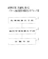
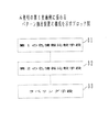
・1つの色の色分解画像から連結領域の外接矩形を求める。
・外接矩形のサイズ及び形状で一定の範囲にあるものだけに絞る。
・矩形毎に隣接矩形探索範囲を設け、その内部にかかる矩形を探索し、お互いに内部にかかる関係の矩形群をグループとして抽出する。
-The circumscribed rectangle of the connected area is obtained from the color separation image of one color.
-Limit the size and shape of the circumscribed rectangle to those within a certain range.
An adjacent rectangle search range is provided for each rectangle, the rectangles that are inside are searched, and a group of rectangles that are inside each other is extracted as a group.
・グループ内の矩形の重心の直線性がよいものだけを残す。
・グループの外接矩形を求め、その内部を対象にグループを構成する領域の色に近いパターンを抽出する。
-A circumscribed rectangle of the group is obtained, and a pattern close to the color of the area constituting the group is extracted with the inside as a target.
しかしながら、従来のカラー画像の同色領域のクラスタリング方法では、以下のような問題があった。
まず、RGB色空間クラスタリング法でも、HSV空間のような他の色空間クラスタリング法でも、画像全体の画素を使用してクラスタリングが行われる。このため、図44に示すように、パターン502の色とパターン507の色とが異なっている場合においても、パターン502の色とパターン507の色とが近い場合には、抽出したいパターン502と別のパターン507とが同じクラスタ508に分類される可能性がある。この場合、パターン507の色の影響で、パターン502の色が本来形成するクラスタ形状が変化する。この結果、パターン502の色が形成するクラスタ本来の色の範囲が歪んでしまい、パターン502を抽出する場合に、精度のよい領域抽出ができなくなってしまう。例えば、抽出したいパターン502の色と近い色のパターン507が別の場所にあり、両者が1つのクラスタ508として抽出されると、クラスタ508が表す色は、パターン502の色とパターン507の色とが混在したものとなり、このクラスタ508が表す色では、パターン502の色の範囲及びパターン508の色の範囲をカバーできず、抽出結果のパターン502’、507’に穴511、512が空いたり、輪郭が綺麗に抽出されなかったりする場合がある。
However, the conventional clustering method of the same color area of a color image has the following problems.
First, clustering is performed using pixels of the entire image in both the RGB color space clustering method and other color space clustering methods such as HSV space. Therefore, as shown in FIG. 44, even when the color of the
また、RGB色空間クラスタリング法や、HSV空間のような他の色空間クラスタリング法では、画像全体の多数の画素を対象としたクラスタリングを行うので、クラスタリングのために必要な計算時間も大きくなる。 In addition, in the RGB color space clustering method and other color space clustering methods such as the HSV space, clustering is performed on a large number of pixels in the entire image, so that the calculation time required for clustering also increases.
また、領域拡張法では、図45に示すように、正規化を行うため、各画素で割り算を行うための計算量が大きくなる。また、割り算の結果を浮動小数点のデータとして全画素分保有する必要があり、処理に必要なメモリ資源が多数必要となる。また、正規化した後でも、隣り合う画素が、人間がみたとき同じように見えるものについても、隣接画素との色の近さをどう定義するかによっては、固定しきい値よりも大きくかけ離れる場合があり、領域中の穴や領域輪郭が正しく抽出できない結果となる場合がある。また、隣接画素との関係だけを見ているので、文字領域と背景領域の境界で徐々に色が変化していく場合には、文字領域が背景領域と同一ラベルになってしまう場合がある。 Further, in the region expansion method, as shown in FIG. 45, normalization is performed, so that the amount of calculation for performing division at each pixel increases. In addition, it is necessary to store the result of division for all pixels as floating point data, and a large number of memory resources are required for processing. In addition, even after normalization, adjacent pixels that look the same when viewed by humans are far apart from the fixed threshold depending on how the color proximity to the adjacent pixels is defined. In some cases, a hole or region outline in the region may not be extracted correctly. In addition, since only the relationship with the adjacent pixels is seen, if the color gradually changes at the boundary between the character area and the background area, the character area may have the same label as the background area.
また、従来の文字領域の抽出方法では、画像全体についての色分解画像が、その画像に存在する色の数だけ生成されるので、色分解画像の生成に時間がかかるという問題がある。各色分解画像は画像全体について生成されるので、例えば、その画像からタイトルを抽出する場合に、タイトル領域以外の色の影響を受けやすく、タイトルの抽出精度が悪化するという問題がある。また、連結領域の外接矩形を求める場合、抽出した色分解画像ごとに画像全体について処理を行う必要があるため、1つのカラー画像から複数(抽出した色数分の)の縦横が同じサイズの画像が必要になり、処理に時間がかかるという問題がある。 In addition, the conventional method for extracting a character region has a problem that it takes time to generate a color separation image because the color separation image for the entire image is generated by the number of colors existing in the image. Since each color separation image is generated for the entire image, for example, when a title is extracted from the image, there is a problem that the extraction accuracy of the title deteriorates because it is easily influenced by colors other than the title region. In addition, when obtaining the circumscribed rectangle of the connected region, it is necessary to perform processing on the entire image for each extracted color separation image, and therefore a plurality of (for the number of extracted colors) vertical and horizontal images having the same size. Is necessary and takes time to process.
また、外接矩形のグルーピングも、画像全体について生成された色分解画像ごとに行われるので、処理に時間がかかるとともに、抽出対象となる文字が異なる色分解画像にクラスタリングされると、救済できないという問題がある。 In addition, since circumscribed rectangle grouping is also performed for each color separation image generated for the entire image, it takes time to process, and if the characters to be extracted are clustered into different color separation images, they cannot be relieved. There is.
また、グループの構成時にお互いに探索範囲にかかる矩形だけを抽出するので、文字パターンの一部であるが、小さい部分がグループから抜け落ち易い。また、抜け落ちた部分を拾うために、グループ内の色が近いパターンの抽出を最後に行うが、この時に色が近いノイズを拾いやすいという問題がある。 In addition, since only the rectangles that are within the search range are extracted from each other when the group is configured, a small portion that is part of the character pattern tends to fall out of the group. In addition, in order to pick up a missing part, a pattern with a similar color in the group is extracted last. However, at this time, there is a problem that it is easy to pick up a noise with a similar color.
そこで、本発明の目的は、抽出対象となるパターンの境界が不明確である場合においても、抽出対象となるパターンを精度良く抽出することが可能なパターン抽出装置を提供することである。 Therefore, an object of the present invention is to provide a pattern extraction apparatus that can accurately extract a pattern to be extracted even when the boundary of the pattern to be extracted is unclear.
上述した課題を解決するために、本発明は、入力画像に含まれるパターンに対する外接矩形を生成する外接矩形生成手段と、前記外接矩形生成手段で生成された外接矩形のうち、所定の範囲の大きさまたは位置の外接矩形を抽出する第1の外接矩形抽出手段と、前記第1の外接矩形抽出手段で抽出された外接矩形から一定の範囲内の探索領域を設定する探索領域設定手段と、前記探索領域にかかる外接矩形を前記外接矩形生成手段で生成された外接矩形の中から抽出する第2の外接矩形抽出手段と、前記第2の外接矩形抽出手段による抽出結果に基づいて、前記入力画像から特定のパターンを抽出するパターン抽出手段とを備えることを特徴とする。 In order to solve the above-described problem, the present invention provides a circumscribed rectangle generating unit that generates a circumscribed rectangle for a pattern included in an input image, and a size of a predetermined range among circumscribed rectangles generated by the circumscribed rectangle generating unit. First circumscribing rectangle extracting means for extracting a circumscribed rectangle of the height or position; search area setting means for setting a search area within a certain range from the circumscribed rectangle extracted by the first circumscribed rectangle extracting means; A second circumscribed rectangle extracting means for extracting a circumscribed rectangle relating to the search area from the circumscribed rectangle generated by the circumscribed rectangle generating means; and the input image based on an extraction result by the second circumscribed rectangle extracting means. And a pattern extracting means for extracting a specific pattern from the pattern.
なお、前記第2の外接矩形抽出手段は、前記外接矩形生成手段で生成された外接矩形が属する縦横の座標に対応して矩形番号を格納する矩形番号格納手段と、前記第1の外接矩形抽出手段で抽出された外接矩形から所定の範囲内の縦横の各座標に含まれる矩形番号を抽出する矩形番号抽出手段と、前記抽出された矩形番号のうち縦横の座標の両方に含まれるものを、前記探索領域にかかる外接矩形として抽出する近傍矩形抽出手段とを備えて構成されるのが望ましい。 The second circumscribed rectangle extracting means includes a rectangle number storing means for storing a rectangle number corresponding to vertical and horizontal coordinates to which the circumscribed rectangle generated by the circumscribed rectangle generating means belongs, and the first circumscribed rectangle extracting. A rectangle number extracting means for extracting a rectangle number included in each vertical and horizontal coordinate within a predetermined range from the circumscribed rectangle extracted by the means, and the extracted rectangular numbers included in both the vertical and horizontal coordinates, It is desirable to include a neighboring rectangle extracting means for extracting as a circumscribed rectangle for the search area.
また、前記矩形番号格納手段は、外接矩形の矩形番号を座標値の順序で格納し、前記矩形番号抽出手段は、最も小さい座標値から順に矩形番号を探索し、座標値が変化するまでの間に含まれる矩形番号をその座標に属する矩形番号として抽出することが望ましい。 The rectangle number storage means stores the rectangle numbers of circumscribed rectangles in the order of coordinate values, and the rectangle number extraction means searches for the rectangle numbers in order from the smallest coordinate value until the coordinate value changes. It is desirable to extract the rectangle numbers included in the as the rectangle numbers belonging to the coordinates.
本発明によれば、入力画像に含まれるパターンに対する外接矩形のうち、探索領域を設定する時の基準となる外接矩形を所定の範囲の大きさまたは位置の外接矩形に限定することにより、入力画像から文字領域等の特定のパターンを抽出する際に、ノイズなどの細かいパターンや背景などの大きなパターンの外接矩形が、文字列を探索する際の探索領域の基準として選択されることを防止することが可能となり、文字列等の特定パターンのみの抽出を効率的に行うことが可能となる。 According to the present invention, among the circumscribed rectangles for the pattern included in the input image, the circumscribed rectangle serving as a reference when setting the search region is limited to the circumscribed rectangle having a predetermined range of size or position. When a specific pattern such as a character area is extracted from a character, a circumscribed rectangle of a fine pattern such as noise or a large pattern such as a background is prevented from being selected as a reference for a search area when searching for a character string. Thus, only a specific pattern such as a character string can be extracted efficiently.
以下、本発明の実施例に係わるパターン抽出装置について図面を参照しながら説明する。
図1は、本発明の第1実施例に係わるパターン抽出装置の構成を示すブロック図である。
Hereinafter, a pattern extraction apparatus according to an embodiment of the present invention will be described with reference to the drawings.
FIG. 1 is a block diagram showing the configuration of a pattern extraction apparatus according to the first embodiment of the present invention.
図1において、色情報算出手段1は、入力画像内のパターンについての色情報を算出する。幾何学情報算出手段2は、入力画像内のパターンについての幾何学情報を算出する。分類手段3は、色情報算出手段1で算出された色情報及び幾何学情報算出手段2でされた幾何学情報に基づいて、入力画像内のパターンの分類を行う。ここで、色情報は、例えば、色空間上でのパターンの色である。また、幾何学情報は、例えば、パターンの大きさや入力画像内での位置、または、他のパターンとの相対的な位置関係である。
In FIG. 1, a color
このように、入力画像内のパターンの分類を行う際に、パターンの色情報だけでなく、パターンの幾何学情報を用いることにより、カラー入力画像内から同一色が付された見出し領域を抽出する場合などにおいて、カラー入力画像内の一部の領域に範囲を限定して、異なるラベルが付された同一色のパターンを1つのグループにまとめたり、特定の位置にあるパターンや所定の大きさのパターンのみに着目して、異なるラベルが付されたパターンを1つのグループにまとめることが可能となる。 As described above, when the patterns in the input image are classified, the heading region with the same color is extracted from the color input image by using not only the pattern color information but also the pattern geometric information. In some cases, the range is limited to a part of the area in the color input image, patterns of the same color with different labels are grouped into one group, or a pattern at a specific position or a predetermined size Focusing only on the pattern, it is possible to combine patterns with different labels into one group.
この結果、見出し領域の存在する可能性の大きな範囲のみについてラベリング処理を行ったり、見出し文字とならないようなノイズなどの小さなパターンや背景などの大きなパターンを処理対象から除去したりすることが可能となり、見出し領域の抽出処理の速度を向上させることが可能となるとともに、見出し領域以外の色の影響を少なくすることが可能となることから、見出し領域の抽出精度も向上させることが可能となる。 As a result, it is possible to perform labeling processing only on the range where there is a high possibility that the heading area exists, or to remove small patterns such as noise and large patterns such as backgrounds that do not become heading characters from the processing target. In addition, it is possible to improve the speed of the extraction process of the heading area and to reduce the influence of colors other than the heading area, so that it is possible to improve the extraction accuracy of the heading area.
図2は、本発明の第2実施例に係わるパターン抽出装置の構成を示すブロック図である。
図2において、クラスタリング手段11は、隣接する画素同士の色情報に基づいて、入力画像内の画素のクラスタリングを行う。グルーピング手段12は、クラスタリング手段11で得られたクラスタ同士の色情報及び幾何学情報に基づいて、クラスタのグルーピングを行う。
FIG. 2 is a block diagram showing the configuration of the pattern extraction apparatus according to the second embodiment of the present invention.
In FIG. 2, the clustering means 11 performs clustering of pixels in the input image based on color information of adjacent pixels. The
このことにより、入力画像内の画素のクラスタリングを行う際には、自分の画素の近隣の画素と色情報を比較すればよく、入力画像内の全ての画素同士を比較する必要がなくなる。 Thus, when performing clustering of pixels in the input image, it is only necessary to compare the color information with the neighboring pixels of the own pixel, and it is not necessary to compare all the pixels in the input image.
この結果、入力画像内の全ての画素同士を比較すると、画素同士の色情報の比較回数が入力画像内の画素数の2乗のオーダーとなるのに対し、自分の画素の近隣の画素と比較した場合には、画素同士の色情報の比較回数を入力画像内の画素数のオーダーで済ませることが可能となり、クラスタリング処理の高速化が可能となる。 As a result, when all the pixels in the input image are compared, the number of comparisons of the color information between the pixels is in the order of the square of the number of pixels in the input image, but compared with the neighboring pixels of the own pixel. In this case, the number of comparisons of color information between pixels can be completed in the order of the number of pixels in the input image, and the clustering process can be speeded up.
また、クラスタリングされたクラスタをグルーピングの際の処理対象とすることにより、同一クラスタ内に存在する画素を一体的に取り扱って処理することが可能となり、個々の画素を処理対象とする必要がなくなることから、グルーピング処理を高速に行うことが可能となる。 In addition, by using clustered clusters as processing targets for grouping, it is possible to handle and process pixels that exist in the same cluster in an integrated manner, eliminating the need to process individual pixels. Therefore, the grouping process can be performed at high speed.
さらに、入力画像内の一部の領域に範囲を限定してクラスタのグルーピングを行ったり、ノイズしか含まれていないような小さなクラスタをグルーピング対象から除いたりすることが可能となることから、グルーピング処理のより一層の高速化を達成することが可能となり、特に、カラー画像などのようにラベル数が莫大な数となるような場合には、効果が大きい。 In addition, it is possible to perform cluster grouping by limiting the range to a part of the area in the input image, or to remove small clusters that contain only noise from the grouping target. It is possible to achieve an even higher speed, and the effect is particularly great when the number of labels is enormous, such as a color image.
図3は、本発明の第3実施例に係わるパターン抽出装置の構成を示すブロック図である。
図3において、色差算出手段21は、所定の色で表現された領域の隣接画素間の色差を算出する。しきい値設定手段22は、色差算出手段21で算出された色差に基づいてしきい値を設定する。ラベリング手段23は、しきい値設定手段22で設定されたしきい値に基づいて、所定の色で表現された画素に隣接する画素のラベリングを行う。
FIG. 3 is a block diagram showing the configuration of the pattern extraction apparatus according to the third embodiment of the present invention.
In FIG. 3, the color difference calculating means 21 calculates the color difference between adjacent pixels in a region expressed in a predetermined color. The
例えば、入力画像が網点印刷法で印刷した印刷物であり、入力画像のパターンの色が、基本となる異なる色のドットの大きさ及びそれらの組み合わせで表現されているものとする。ここで、基本となる異なる色のドットの大きさが小さいために、基本となる異なる色のドットの大きさ及びそれらの組み合わせで1つの色を表現した時に、肉眼では、各ドットごとの色の違いが識別できず、その色が単一色と見える場合でも、デバイスの読み取り解像度が各ドットごとの色の違いを判別できるほど大きい場合には、肉眼では単一色と見える領域が、デバイスにとっては単一色ではないと判断される。 For example, it is assumed that the input image is a printed matter printed by the halftone printing method, and the color of the pattern of the input image is expressed by the dot sizes of different basic colors and combinations thereof. Here, since the size of the dots of different basic colors is small, when one color is expressed by the size of the basic dots of different colors and combinations thereof, the color of each dot is visually recognized by the naked eye. Even if the difference cannot be identified and the color appears to be a single color, if the reading resolution of the device is large enough to distinguish the color difference for each dot, the area that appears to be a single color to the naked eye is It is judged that it is not one color.
このため、このデバイスの読み取り結果をそのまま用いて、ラベリングを行うと、肉眼では単一色と見える1つのパターンに異なったラベルが付され、このラベリング結果に基づいて抽出されたパターンを人間に提示すると、人間が1つのパターンと認識する部分に、穴が開いたり、欠けが発生したりして、パターンの抽出精度が悪化する。 For this reason, when labeling is performed using the reading result of this device as it is, a different label is attached to one pattern that appears to be a single color to the naked eye, and a pattern extracted based on this labeling result is presented to a human being. A hole is formed or a chip occurs in a portion that a human recognizes as one pattern, and the pattern extraction accuracy deteriorates.
そこで、肉眼で単一色と見える部分について、デバイスで読み取った際の色の変動を求め、その色の変動の範囲内にある画素に同一のラベルを付すことにより、肉眼で単一色と見える1つのパターンに同一のラベルを付すことが可能となり、人間が1つのパターンと認識する部分に、穴が開いたり、欠けが発生したりすることを防止することが可能となる。 Therefore, for a portion that appears to be a single color with the naked eye, the variation in color at the time of reading with the device is obtained, and by attaching the same label to pixels within the range of the color variation, It is possible to attach the same label to the pattern, and it is possible to prevent a hole from being formed or a chipping from occurring in a portion that a human recognizes as one pattern.
図4は、本発明の第4実施例に係わるパターン抽出装置の構成を示すブロック図である。
図4において、第1の色情報比較手段31は、入力画像の隣接画素間の色情報を比較する。第2の色情報比較手段32は、第1の色情報比較手段31で比較対象となった画素の色情報と、前記画素に隣接するラベル画像の色情報とを比較する。ラベリング手段33は、第1の色情報比較手段31の比較結果及び第2の色情報比較手段32の比較結果に基づいて、ラベリングを行う。ここで、ラベル画像の色情報は、例えば、同一ラベルが付された画素の色情報の平均値である。
FIG. 4 is a block diagram showing the configuration of the pattern extraction apparatus according to the fourth embodiment of the present invention.
In FIG. 4, the first color information comparison means 31 compares color information between adjacent pixels of the input image. The second color
例えば、入力画像のタイトル領域の色が徐々に変化しているため、タイトルを構成する文字列と背景の境界が不明確になっているものとする。この場合に、互いに隣接する画素の色情報を比較しただけでは、互いに隣接する画素間では色が似ているために、それらの画素に同一のラベルが付され、それらの画素を順々に辿っていくと、タイトル領域内に背景のパターンが取り込まれ、タイトルとは色が明らかに異なる画素にまで同一のラベルが付されることがある。 For example, since the color of the title area of the input image is gradually changing, it is assumed that the boundary between the character string constituting the title and the background is unclear. In this case, simply comparing the color information of the pixels adjacent to each other, the colors are similar between the pixels adjacent to each other, so the same label is attached to the pixels, and the pixels are traced sequentially. As a result, a background pattern is captured in the title area, and the same label may be attached even to pixels that are clearly different in color from the title.
ここで、互いに隣接する画素間だけについて色情報を比較するのではなく、既にラベル付けがされているパターンの色情報との比較も行って、ラベル付けを行うことにより、色が徐々に変化する場合においても、タイトル領域と背景との間の境界を検出することが可能となる。 Here, instead of comparing color information only between pixels adjacent to each other, color is gradually changed by performing labeling by comparing with color information of an already labeled pattern. Even in this case, the boundary between the title area and the background can be detected.
図5は、本発明の一実施例に係わるパターン抽出装置のシステム構成を示すブロック図である。
図5において、41は全体的な処理を行う中央演算処理ユニット(CPU)、42はリードオンリメモリ(ROM)、43はランダムアクセスメモリ(RAM)、44は通信インターフェイス、45は通信ネットワーク、46はバス、47は入出力インターフェイス、48は見出し文字などの認識結果などを表示するディスプレイ、49は見出し文字などの認識結果などを印刷するプリンタ、50はスキャナ51により読み取られたデータを一時的に格納するメモリ、51は入力画像などを読み取るスキャナ、52はキーボード、53は記憶媒体を駆動するドライバ、54はハードディスク、55はICメモリカード、56は磁気テープ、57はフレキシブルディスク、58はCD−ROMやDVD−ROMなどの光ディスクである。
FIG. 5 is a block diagram showing a system configuration of a pattern extraction apparatus according to an embodiment of the present invention.
In FIG. 5, 41 is a central processing unit (CPU) that performs overall processing, 42 is a read only memory (ROM), 43 is a random access memory (RAM), 44 is a communication interface, 45 is a communication network, 46 is Bus, 47 is an input / output interface, 48 is a display for displaying the recognition result of the headline character, 49 is a printer for printing the recognition result of the headline character, etc. 50 is temporarily storing the data read by the
パターン抽出処理を行うプログラムなどは、ハードディスク54、ICメモリカード55、磁気テープ56、フレキシブルディスク57、光ディスク58などの記憶媒体に格納される。そして、パターン抽出処理を行うプログラムなどを、これらの記憶媒体からRAM43に読み出すことにより、パターン抽出処理を行うことができる。また、パターン抽出処理を行うプログラムなどを、ROM42に格納しておくこともできる。
A program for performing pattern extraction processing is stored in a storage medium such as the hard disk 54, the
さらに、パターン抽出処理を行うプログラムなどを、通信インターフェイス44を介して通信ネットワーク45から取り出すこともできる。通信インターフェイス44に接続される通信ネットワーク45として、例えば、LAN(LocalArea Network)、WAN(Wide Area Network)、インターネット、アナログ電話網、デジタル電話網(ISDN:IntegralService Digital Network)、PHS(パーソナルハンディシステム)や衛星通信などの無線通信網を用いることができる。 Furthermore, a program for performing pattern extraction processing can be extracted from the communication network 45 via the communication interface 44. The communication network 45 connected to the communication interface 44 includes, for example, a LAN (Local Area Network), a WAN (Wide Area Network), the Internet, an analog telephone network, a digital telephone network (ISDN: Integral Service Digital Network), and a PHS (Personal Handy System). Wireless communication networks such as satellite communication can be used.
CPU41は、パターン抽出処理を行うプログラムが起動されると、スキャナ51により読み取られた入力画像のラベリングを行うしきい値を設定し、スキャナ51により読み取られた入力画像からラベル画像を生成する。ラベル画像が生成されると、入力画像のパターンの各ラベルごとに、各パターンについての外接矩形を生成する。そして、各外接矩形内の領域の色情報及び外接矩形の幾何学情報に基づいて、各外接矩形のグルーピングを行い、このグルーピングされた外接矩形の配置状態や大きさなどを考慮して、タイトル領域などを抽出する。タイトル領域が抽出されると、このタイトル領域に含まれているパターンを入力画像から抽出されたタイトルとしてディスプレイ48やプリンタ49に出力したり、このタイトル領域に含まれるパターンの文字認識を行い、その認識結果に基づいて、文書の自動検索を行ったりする。
When the program for performing the pattern extraction process is activated, the
図6は、本発明の第5実施例に係わるパターン抽出装置の構成を示すブロック図である。
図6において、61はカラー画像入力装置、62は外部出力装置、63はメモリ、64は演算装置(CPU)、65は画像縮小手段、66は可変しきい値設定手段、67はラベリング手段である。
FIG. 6 is a block diagram showing the configuration of the pattern extraction apparatus according to the fifth embodiment of the present invention.
In FIG. 6, 61 is a color image input device, 62 is an external output device, 63 is a memory, 64 is an arithmetic unit (CPU), 65 is an image reduction means, 66 is a variable threshold value setting means, and 67 is a labeling means. .
カラー画像入力装置1からカラー画像信号が入力されると、画像縮小手段65が、例えば、画素数で1/9の縮小画像を作成する。そして、この縮小画像において、領域拡張法などの手法を用いて、多少の色差を許容するラベリングを行い、同一ラベル領域を示すラベル画像と同一ラベル領域を囲む外接矩形を求める。
When a color image signal is input from the color
この際、隣接画素と同一ラベルを与える色の値の差のしきい値は、領域拡張法のような固定ではなく、対象となる色により可変にする。このしきい値は、例えば、対象となる色に応じて、予め作成したテーブルを可変しきい値設定手段66が参照することにより得られる。 At this time, the threshold value of the difference between the color values giving the same label as that of the adjacent pixel is not fixed as in the region expansion method but is made variable depending on the target color. This threshold value is obtained, for example, by referring to a previously created table by the variable threshold value setting means 66 according to the target color.
このように、縮小画像上で求めた同一ラベル領域を探索して、その中の色を表現する(R,G,B)などの数値列の種類を全て調査して、これをこのラベルの属性として記憶する。また、この色の種類から、このラベルの代表色も求める。 In this way, the same label area obtained on the reduced image is searched, all types of numerical sequences such as (R, G, B) expressing colors in the reduced area are investigated, and this is the attribute of this label. Remember as. Also, the representative color of this label is obtained from this color type.
次に、このような縮小画像で求めた外接矩形を原画像に反映させ、この矩形内部だけを走査して代表色に近い色を検出し、この画素から隣接画素に対するラベリングを行う。ただし、同一と見なす色は前記の処理により同一色と見なした色の種類である。 Next, the circumscribed rectangle obtained from such a reduced image is reflected in the original image, only the inside of the rectangle is scanned to detect a color close to the representative color, and labeling of the adjacent pixel from this pixel is performed. However, the colors regarded as the same are the types of colors regarded as the same color by the above processing.
そして、原画像から求めたラベル画像の中から、対象となる業務に適した特定領域抽出を行う。例えば、大きな文字で記載されている見出しや、タイトルなどのキーワードとなる文字の領域をカラー文書から抽出する場合には、外接矩形の大きさや並びの情報を使った文字列抽出技術で、対象となる文字列領域だけを抽出すればよい。 Then, a specific area suitable for the target business is extracted from the label image obtained from the original image. For example, when extracting a character area that is a keyword such as a headline or a title written in large characters from a color document, the character string extraction technology using the size of the circumscribed rectangle and the information of the arrangement is used. It is sufficient to extract only the character string region.
図7は、本発明の第6実施例に係わるパターン抽出装置の構成を示すブロック図である。
図7において、71はカラー画像入力装置、72は外部出力装置、73はメモリ、74は演算装置である。カラー画像入力装置71は、外部のカラー画像をRGB信号で入力するものであり、例えば、CCDカメラとか、スキャナ等である。
FIG. 7 is a block diagram showing the configuration of the pattern extraction apparatus according to the sixth embodiment of the present invention.
In FIG. 7, 71 is a color image input device, 72 is an external output device, 73 is a memory, and 74 is an arithmetic device. The color
外部出力装置72は、演算装置74により種々の処理が行われた結果得られた処理結果を出力するものであり、例えば、ディスプレイ等で構成されている。メモリ73は画像情報やしきい値情報を保持するものであり、カラー画像入力装置71から入力されたカラー画像信号を保持したり、保持されたカラー画像信号を演算装置74が処理を行うことにより得られた処理結果等を保持したりする。
The
演算装置74は、カラー画像入力装置71により入力されたカラー画像信号に対して縮小画像を作成したり、ラベリング処理したり、特定領域抽出処理したり等の各種処理を行うものであり、画像縮小手段75、可変しきい値設定手段76、ラベリング手段77、外接矩形処理78、原画像ラベリング手段79、特定領域抽出手段80等を具備する。
The
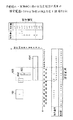
図8は、図7のカラー画像処理装置の動作を示すフローチャートである。
図8において、例えば、カラー文書のような被写体を、CCDカメラやスキャナ等の撮像装置の如きカラー画像装置71で入力し、得られたカラー画像をメモリ73に保存する(ステップS1)。
FIG. 8 is a flowchart showing the operation of the color image processing apparatus of FIG.
In FIG. 8, for example, a subject such as a color document is input by a
次に、このメモリ73上に保存されたカラー画像を、画像縮小手段75が固定縮小率で、あるいは、縮小後に規定の大きさになるような縮小率で縮小して、メモリ73にセットする(ステップS2)。この縮小率は記録しておく。縮小方法は、例えば、図9(a)に示すように、1/3に縮小する場合には(R,G,B)で表現された原画像の3×3の領域を縮小画像1×1に対応させることになるが、この場合、原画像の3×3の領域内部の9ケの画素の色の(R,G,B)を1単位として、図9(b)に示すヒストグラムを作成し、最頻値を対応する縮小画像の画素の値としてセットする。
Next, the color image stored in the
もしも、1つで決まる最頻値がなければ、次の複数値のうちの、いずれか1つを予め定めたアルゴリズムで選出して、これを対応する縮小画像の画素の値とする。
一般的には、原画像のn×nの領域を縮小画像の1×1に対応させるような1/nの縮小率で縮小する場合は、原画像のn×nの領域内部にある画素の色の(R,G,B)を1単位として扱ったヒストグラムを作成し、例えば、その中間値とか最頻値を対応する縮小画像の画素の値とするものである。
If there is no mode value determined by one, one of the next multiple values is selected by a predetermined algorithm, and this is set as the pixel value of the corresponding reduced image.
In general, when reducing an n × n area of an original image at a reduction ratio of 1 / n so as to correspond to 1 × 1 of a reduced image, pixels in the n × n area of the original image A histogram in which the color (R, G, B) is handled as one unit is created, and for example, the intermediate value or the mode value is used as the pixel value of the corresponding reduced image.
ここで、縮小画像にセットする値は、原画像の対応するn×nの領域内部にある画素の色の平均値などのような作り出した値ではなく、あくまでも、原画像に存在する値を使用する。 Here, the value set in the reduced image is not a value created such as the average value of the colors of the pixels in the corresponding n × n area of the original image, but a value existing in the original image is used to the last. To do.
次に、このように縮小処理した縮小画像に対し、ラベリング手段77が色ラベリング処理、すなわち、縮小画像を対象として隣り合う画素の色が近い場合に同一ラベルを与える処理を行う(ステップS3)。すなわち、縮小画像に対し、その左上からラスタスキャンを行い、ラベル付けがされていない画素に注目し、この画素に今まで付けたラベル値よりも+1したラベル値を付与する。
Next, the
例えば、図10(a)に示すように、注目画素Cのカラーの値を(Rc,Gc,Bc)とし、この注目画素Cの周りの8画素を1〜8とし、これら周りの8画素のカラーの値を(Ri,Gi,Bi)(i=1〜8)とするとき、それぞれの画素のカラーの値(Ri,Gi,Bi)値を求める。すなわち、画素1,2,...8についてのカラーの値(R1,G1,B1),(R2,G2,B2)・・・(R8,G8,B8)を求める。
For example, as shown in FIG. 10A, the color value of the pixel of interest C is (Rc, Gc, Bc), 8 pixels around this pixel of interest C are 1 to 8, and the 8 pixels around these pixels are When the color value is (Ri, Gi, Bi) (i = 1 to 8), the color value (Ri, Gi, Bi) value of each pixel is obtained. That is,
そして、注目画素のカラーの値(Rc,Gc,Bc)との距離dci(i=1〜8)を求め、それがR,G,Bについてしきい値(Rth,Gth,Bth)より小さい値の場合に注目画素と同一ラベルを付ける。例えば、画素1と注目画素Cとの距離dclを求める場合、R,G,Bの各カラー毎にそれぞれの値がしきい値Tth,Gth,Bth以内にあるか否かを求め、3色ともしきい値よりも小さいとき、つまり類似している場合に、Cと同じラベルをiに与えるためにdciに小さな値を与える。しかし、1色の値でもしきい値以上のとき、別のラベルを付与するための大きな値(しきい値thより大きな値)を与える。この距離dclは、下記のようにして求められる。
Then, the distance dci (i = 1 to 8) with the color value (Rc, Gc, Bc) of the target pixel is obtained, and the value is smaller than the threshold value (Rth, Gth, Bth) for R, G, B. In this case, the same label as the target pixel is attached. For example, when the distance dcl between the
dcl=|Rc−Rl|<Rth
and|Gc−Gl|<Gth
and|Bc−Bl|<Bth ・・・(1)
そして、(1)式が成立するとき、dcl=0として同一ラベルを与え、不成立のとき、dcl=1000などのしきい値よりも大きな値を付与する。一般的には、図10(b)に示すように、以下の式で距離dci(i=1〜8)を示すことができる。
dcl = | Rc−Rl | <Rth
and | Gc-Gl | <Gth
and | Bc-Bl | <Bth (1)
When the expression (1) is established, the same label is given as dcl = 0, and when it is not established, a value larger than a threshold value such as dcl = 1000 is given. In general, as shown in FIG. 10B, the distance dci (i = 1 to 8) can be expressed by the following equation.
0 if|Rc−Ri|<Rth and
|Gc−Gi|<Gth and
|Bc−Bi|<Bth
10000 それ以外の条件
ただし、1000はこれに限定されるものではなく、しきい値より大きい値を示す。
0 if | Rc-Ri | <Rth and
| Gc-Gi | <Gth and
| Bc-Bi | <Bth
10,000 Other conditions However, 1000 is not limited to this, and indicates a value larger than the threshold value.
なお、カラー毎のしきい値(Rth,Gth,Bth)は、CCDカメラやスキャナなどの入力装置と被写体に依存したサンプルから予め求めておいた表を用いる。しかも、注目画素の色の値(R,G,B)をキーとして、この色の値に応じて予めしきい値を定めておく。 For the threshold values (Rth, Gth, Bth) for each color, a table obtained in advance from an input device such as a CCD camera or a scanner and a sample depending on the subject is used. In addition, a threshold value is set in advance according to the color value (R, G, B) of the target pixel as a key.
例えば、図11(a)に示すように、入力画像について予想される注目画素の色の値(R,G,B)の全ての組み合わせをエントリとして持つ表を引いて、色の各要素毎に、要素毎に独立して定められたしきい値(Rth,Gth,Bth)を求める。例えば、図11(a)のテーブルでは、注目画素のカラーの値が(R1,G1,B1)のときのしきい値がR,G,Bについて、それぞれ(Rth1,Gth1,Bth1)であり、注目画素のカラー値が(R2,G2,B2)のときのしきい値が(Rth2,Gth2,Bth2)である。 For example, as shown in FIG. 11A, a table having entries of all combinations of color values (R, G, B) of the target pixel expected for the input image is drawn, and each color element is subtracted. The threshold values (Rth, Gth, Bth) determined independently for each element are obtained. For example, in the table of FIG. 11A, the threshold values when the color value of the pixel of interest is (R1, G1, B1) are (Rth1, Gth1, Bth1) for R, G, B, respectively. The threshold value when the color value of the pixel of interest is (R2, G2, B2) is (Rth2, Gth2, Bth2).
図11(a)の場合は、予めサンプルの分布から予想される注目画素の色の値をキーとして、全ての色の値の組み合わせをエントリとして持つしきい値参照表を用意しておき、注目画素の色の組み合わせにより、このしきい値参照表を参照する例を示したので、表の大きさがこれらの各色の組み合わせの分だけ必要となり、非常に大きなものとなる。 In the case of FIG. 11 (a), a threshold value reference table having entries of combinations of all color values as entries using the color value of the target pixel predicted from the sample distribution as a key is prepared in advance. Since an example in which this threshold value reference table is referred to by a combination of pixel colors is shown, the size of the table is required by the combination of each of these colors, which is very large.
ここで、しきい値参照表の大容量化を防止するために、しきい値参照表のエントリには全ての(R,G,B)の組み合わせは持たずに、(R,G,B)の値でクラスタリングを行った結果の(R,G,B)の代表エントリだけを持つようなしきい値参照表を用意して、注目画素の(R,G,B)の値と代表エントリとの距離値つまり類似度を求め、最も近い代表エントリを抽出して、それをキーにして色の各要素独立のしきい値(Rth,Gth,Bth)を求めることもできる。 Here, in order to prevent an increase in the capacity of the threshold value reference table, the entries in the threshold value reference table do not have all (R, G, B) combinations, but (R, G, B). A threshold value reference table having only (R, G, B) representative entries as a result of clustering with the values of the values of the pixel of interest (R, G, B) and representative entries is prepared. It is also possible to obtain a distance value, that is, a similarity, extract the nearest representative entry, and use it as a key to obtain an independent threshold value (Rth, Gth, Bth) for each color element.
また、しきい値参照表の大容量化を防止するため、各色の値をN階層に表現したとき、例えば、N=256に表現したとき、カラー値毎にそのカラーに対するしきい値を記入したしきい値参照表を各カラー毎に用意し、カラー毎にしきい値をこれらのしきい値参照表より個別に求めれば、しきい値参照表の容量は、256×3のエントリ数で済むので大幅に小さくすることができる。例えば、注目画素のカラー値が(R1,G2,B2)の場合、図11(b)に示すように、R1に対するしきい値としてしきい値参照表Rを参照して、DRth1を求め、G2に対するしきい値としてしきい値参照表Gを参照して、Gth2を求め、B2に対するしきい値としてしきい値参照表Bを参照として、Bth2を求めることができる。 In order to prevent an increase in the capacity of the threshold reference table, when each color value is expressed in N layers, for example, when N = 256, the threshold value for that color is entered for each color value. If a threshold value reference table is prepared for each color and a threshold value is obtained for each color separately from these threshold value reference tables, the capacity of the threshold value reference table can be 256 × 3 entries. It can be greatly reduced. For example, when the color value of the target pixel is (R1, G2, B2), as shown in FIG. 11 (b), DRth1 is obtained by referring to the threshold value reference table R as a threshold value for R1, and G2 Gth2 can be obtained by referring to the threshold value reference table G as a threshold value for B, and Bth2 can be obtained by referring to the threshold value reference table B as a threshold value for B2.
さらに、しきい値を求めるしきい値参照表の形式として、図11(a)に示した全ての(R,G,B)の組み合わせではなく、図12に示すように、カラー値について複数のグループに分け、各グループ毎にしきい値を定めることもできる。図12は各カラー値について4階層毎に1つのしきい値を定めた例であり、R1〜R4については同じしきい値Rt1を、R5〜R8については同じしきい値Rt2・・・、同様にG1〜G4について同じしきい値Gt1を・・・、また、BN−3〜BNについては同じしきい値BtMを定めた例である。 Further, as a format of the threshold value reference table for obtaining the threshold value, as shown in FIG. 12, instead of all the combinations of (R, G, B) shown in FIG. It is also possible to divide into groups and set a threshold value for each group. FIG. 12 shows an example in which one threshold value is defined for each color value for every four layers, the same threshold value Rt1 for R1 to R4, the same threshold value Rt2 for R5 to R8, and the like. The same threshold Gt1 is set for G1 to G4, and the same threshold BtM is set for BN-3 to BN.
これらのしきい値参照表は、特に対象物が印刷物でスキャナ入力の場合では、印刷物の状態をモデル化したものから自動的に作ることもできる。次に、このラベル処理した縮小画像、つまりラベル画像に対しても外接矩形処理を外接矩形処理手段78が行う(ステップS4)。すなわち、ステップS3において、縮小画像についてのラベリングの結果、同一領域は同じラベル値が付与される。そして、この同一領域について外接矩形を求める。 These threshold value reference tables can be automatically generated from a model of the state of the printed material, particularly when the object is a printed material and is input from a scanner. Next, circumscribed rectangle processing means 78 performs circumscribed rectangle processing on the reduced image subjected to the label processing, that is, the label image (step S4). That is, in step S3, the same label value is assigned to the same region as a result of labeling the reduced image. Then, a circumscribed rectangle is obtained for the same region.
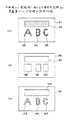
例えば、図13(a)に示すように、文字領域93〜95と他の領域92の色が異なっているカラー画像91が入力された場合、図13(b)に示す縮小ラベル画像96が生成され、縮小ラベル画像96から外接矩形98〜100を求めることができる。
For example, as shown in FIG. 13A, when a
図13(b)において、矩形領域97は図13(a)に示す背景領域92に対応し、矩形領域98〜100はそれぞれ図13(a)に示す文字領域93〜95に対応する。
それから、ラベル画像において、同一ラベルとして記録されている画素を走査して、その中の色の種類を全て記録する。この記録は、各外接矩形の属性情報として記録する。また、ラベル画像で同一ラベルとして記録されている全ての画素から、各ラベルの代表色を1つ求める。この求め方は、例えば、色の種類毎に頻度分布を求め、最も頻度の高い色を代表色にするというような手法で求めることができる。この代表色情報も、外接矩形の属性情報として記録する。
In FIG. 13B, a
Then, in the label image, the pixels recorded as the same label are scanned to record all kinds of colors therein. This recording is recorded as attribute information of each circumscribed rectangle. Further, one representative color of each label is obtained from all the pixels recorded as the same label in the label image. This method can be obtained, for example, by a method in which a frequency distribution is obtained for each color type and the most frequently used color is used as a representative color. This representative color information is also recorded as attribute information of the circumscribed rectangle.
また、このラベリング処理の結果として、ラベリング手段77は次のような出力情報を作成する。ラベル画像として、1画素あたり2バイト情報であり、縮小画像領域の高さ及び幅のサイズ、縮小率が示される。そして、この縮小画像領域内に存在する矩形数nrとその矩形情報が示される。矩形情報としては、その領域内に存在する矩形の数を示す矩形数nr、矩形番号、この矩形に内包するラベル画像のラベル番号、矩形左上座標(x1,y1)、矩形右下座標(x2,y2)、矩形内の代表色(Rs,Gs,Bs)、色の種類数nc、色の種類(R0,G0,B0)、(R1,G1,B1)・・・(Rn−1,Gn−1,Bn−1)等が出力される。 As a result of this labeling process, the labeling means 77 creates the following output information. The label image is 2-byte information per pixel, and indicates the height and width size of the reduced image area, and the reduction rate. Then, the number of rectangles nr existing in the reduced image area and the rectangle information thereof are shown. As the rectangle information, the number of rectangles nr indicating the number of rectangles existing in the area, the rectangle number, the label number of the label image included in the rectangle, the rectangle upper left coordinates (x1, y1), the rectangle lower right coordinates (x2, y2), the representative colors (Rs, Gs, Bs) in the rectangle, the number of color types nc, the color types (R0, G0, B0), (R1, G1, B1)... (Rn-1, Gn- 1, Bn-1) and the like are output.
次に、原画像ラベリング手段79は前記出力情報を受けて、先ず、縮小画像で作られた矩形情報の左上座標値と右下座標値をそれぞれ縮小率で割って、対応する原画像での座標を求める。縮小率が1/nの場合は原画像の矩形は、左上座標が(x1*n,y1*n)であり、右下座標が{(x2*n)−1,(y2*n)−1}である。ここで、*は乗算を示し、右下座標は1画素戻すために−1する。 Next, the original image labeling means 79 receives the output information, and first divides the upper left coordinate value and the lower right coordinate value of the rectangular information created by the reduced image by the reduction ratio, respectively, and coordinates in the corresponding original image Ask for. When the reduction ratio is 1 / n, the rectangle of the original image has an upper left coordinate (x1 * n, y1 * n) and a lower right coordinate {(x2 * n) −1, (y2 * n) −1. }. Here, * indicates multiplication, and the lower right coordinate is decremented by 1 to return one pixel.
原画像ラベリング手段79は、この座標で示される原画像の矩形内をラスタスキャンして、既にラベルが付いていないもので、かつ、前記代表色(Rs,Gs,Bs)に近い画素を探す。近いということは、その画素のカラー値を(Ri,Gi,Bi)とするとき、例えば、
|Rs−Ri|<Rth
and
|Gs−Gi|<Gth
and
|Bs−Bi|<Bth
を満たすことである。なお、ここでのしきい値Rth,Gth,Bthは、固定値である。
The original image labeling means 79 performs a raster scan within the rectangle of the original image indicated by these coordinates, and searches for pixels that have not been labeled and are close to the representative colors (Rs, Gs, Bs). That is, when the color value of the pixel is (Ri, Gi, Bi), for example,
| Rs-Ri | <Rth
and
| Gs-Gi | <Gth
and
| Bs-Bi | <Bth
Is to satisfy. Note that the threshold values Rth, Gth, and Bth here are fixed values.
この条件を満足する画素を検出したら、この画素に今まで付けたラベル値+1のラベル値を付与する。それから、この注目した画素の周囲8画素を走査して、それぞれの画素のカラー値(Ri,Gi,Bi)を求め、注目画素のカラー値(Rc,Gc,Bc)との関係が、
|Rc−Ri|<Rth
and
|Gc−Gi|<Gth
and
|Bc−Bi|<Bth
を満たすときに注目画素と同一ラベルを付与する(ステップS5)。
When a pixel satisfying this condition is detected, a label value of the label value + 1 added up to this pixel is assigned. Then, the surrounding eight pixels of the pixel of interest are scanned to obtain the color value (Ri, Gi, Bi) of each pixel, and the relationship with the color value (Rc, Gc, Bc) of the pixel of interest is
| Rc-Ri | <Rth
and
| Gc-Gi | <Gth
and
| Bc-Bi | <Bth
When the condition is satisfied, the same label as the target pixel is given (step S5).
また、この処理で同一ラベルを付与されなかった場合でも、現在注目している矩形の前記属性情報である色の種類全てと比較して同様の距離を求め、それがしきい値よりも小さい場合に、注目画素と同一ラベルを付与する。 Also, even when the same label is not given in this process, the same distance is obtained by comparing with all the types of colors as the attribute information of the currently focused rectangle, and it is smaller than the threshold value Are given the same label as the pixel of interest.
このようにして、図13(c)に示すように、各矩形内97〜100で代表色に近い画素に注目してラベル付けすることにより、その矩形領域97〜100内に存在する同じカラー値により構成される画素の領域102〜105が抽出される。なお、実際のカラー文書において、画像領域が図13(a)に示すように大まかではなく、背景や色文字も種々の大きさのものが混在している場合には、同一ラベル領域も、図13(c)に示したように単純なものではなく、複雑なものとなる。
In this way, as shown in FIG. 13C, by labeling with attention to pixels close to the representative color in each of the
次に、このように原画像から求めたラベル画像101の中から、特定領域抽出手段80が、対象となる業務に適した特定領域抽出を行う(ステップS6)。例えば、カラー文書から大きな文字で記載されている見出しや、タイトル等のキーワードとなる文字の領域を抽出する場合には、予め通知された外接矩形の大きさや、並びの情報を使用した従来の文字列抽出の手法に基づき、対象となる文字列領域だけを抽出することができる。
Next, from the
例えば、抽出された矩形情報を対象として、矩形の隣接関係を求める。そして、上下または左右の矩形で座標値が近く、つまり、座標値の差がしきい値内に入り、かつ、(R,G,B)の各色差がしきい値内に入るものを文字列として抽出する。そして、これを外部出力装置72において、例えば、表示出力する。
For example, the rectangular adjacent relationship is obtained for the extracted rectangular information. A character string in which the coordinate values are close to each other in the upper and lower or left and right rectangles, that is, the difference between the coordinate values falls within the threshold value and each color difference of (R, G, B) falls within the threshold value. Extract as Then, this is output and displayed, for example, in the
また、カラー情景画像から1つの物体を抽出する場合には、ラベル画像で隣り合う領域の代表色をHSV(色相、彩度、明度)等の情報に変換し、色相が近いものを併合処理する。これにより、陰などの影響で分割されていたものを1つの領域にまとめることができる。そして、ある程度の面積を持つ領域を物体の候補領域として出力する。 When one object is extracted from a color scene image, the representative colors of adjacent areas in the label image are converted into information such as HSV (hue, saturation, brightness), and those having similar hues are merged. . Thereby, what was divided | segmented by the influence of shadow etc. can be put together into one area | region. Then, an area having a certain area is output as an object candidate area.
このように、本発明の第6実施例では、縮小画像によりある程度同じ色でまとまった領域を求め、その範囲だけを原画像で精密に抽出するようにしたので、処理時間を非常に短縮することができる。また、隣り合う画素だけを対象にして、しかも、画素の色に従ったしきい値を用いてラベリングを行うので、局所的に精密な色クラスタリングが可能となり、例えば、抽出したい領域とその背景の色が近い場合にも、別に区別することが可能となり、精度のよい領域抽出ができる。 As described above, in the sixth embodiment of the present invention, a region grouped with a certain amount of the same color is obtained from the reduced image, and only the range is precisely extracted from the original image, so that the processing time is greatly reduced. Can do. In addition, since labeling is performed only on adjacent pixels and using a threshold value according to the color of the pixel, locally precise color clustering is possible, for example, the region to be extracted and its background Even when colors are close to each other, it is possible to distinguish them separately, and it is possible to extract a region with high accuracy.
また、注目画素の色に応じたしきい値を求めるとき、注目画素の色の3要素をキーとして予め用意されているテーブルを参照すればよいので、しきい値を求めるためにアクセスする計算量が少なくてよい。 Further, when obtaining a threshold value corresponding to the color of the target pixel, it is only necessary to refer to a table prepared in advance using three elements of the color of the target pixel as a key. There may be little.
そして、注目画素の色に応じたしきい値を求めるとき、注目画素の3要素とテーブルのエントリである色の3要素との距離値の類似度を求めて注目画素の色に最も近いエントリを抽出してそこに記録されているしきい値を求めるので、しきい値の記録されているテーブルの容量を小さくすることができる。 Then, when obtaining a threshold value corresponding to the color of the target pixel, the similarity of the distance value between the three elements of the target pixel and the three elements of the color that is an entry in the table is obtained, and the entry closest to the color of the target pixel is obtained. Since the threshold value extracted and recorded there is obtained, the capacity of the table in which the threshold value is recorded can be reduced.
しかも、色の3要素に対する独立のしきい値を、CCDカメラとか、スキャナなどの入力機器と被写体に依存したサンプルの分布から予め求めていた表を用いて決めるので、入力機器に依存したしきい値を持つ表を作ることができるため、正確なラベル付与を行うことができる。 In addition, since the independent threshold values for the three elements of color are determined using a table obtained in advance from the distribution of samples depending on the input device such as a CCD camera or a scanner and the subject, the threshold depends on the input device. Since a table with values can be created, accurate labeling can be performed.
次に、本発明の一実施例に係わるラベリングの際のしきい値の設定方法について説明する。雑誌などのカラー印刷物は、グラビア等、色々な印刷方法があるが、網点印刷法で印刷されたものが、世の中には多い。網点印刷法で印刷された印刷部では、人間の目には均一色と見える領域でも、拡大してみると、カラーのモアレ模様が生じている。 Next, a threshold value setting method for labeling according to an embodiment of the present invention will be described. Color prints such as magazines have various printing methods such as gravure, but many are printed by halftone printing. In a printing section printed by the halftone printing method, even when an area that appears to be a uniform color to the human eye is enlarged, a color moire pattern is generated.
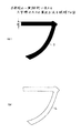
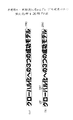
図14は、網点印刷におけるカラーのモアレ模様を示す図である。
図14(a)において、原画像111内の「の」と書かれた領域は、例えば、オレンジ色の一色で描かれているが、図14(b)に示すように、「の」と書かれた領域の一部を拡大すると、その領域は、様々の色が集まって構成されている。
FIG. 14 is a diagram showing a color moire pattern in halftone printing.
In FIG. 14A, an area written “NO” in the
このため、隣接画素の色差(RGBの輝度差など)を固定しきい値と比較して、それらの画素に同一ラベルを与えるか否かを判断すると、適応できない場合がある。例えば、図14の「の」と書かれた領域内の画素111〜113は、「の」と書かれた領域内のその他の画素と異なるラベルが付され、原画像111から「の」の文字を抽出する際に、画素112〜114の部分が欠落し、抽出精度が悪化する。
For this reason, it may not be adaptable if the color difference between adjacent pixels (such as the luminance difference of RGB) is compared with a fixed threshold value to determine whether or not to give the same label to those pixels. For example, the
そこで、印刷モデルを用いて、RGBの平均輝度値とスキャナ読み取り解像度ごとの隣接画素のRGB各輝度差を予め求め、それらの結果を色差テーブルに格納しておく。そして、色差テーブルを参照しながら、各色ごとにしきい値を制御することにより、ラベリングを行う。 Therefore, using the print model, the RGB average luminance value and the RGB luminance difference between adjacent pixels for each scanner reading resolution are obtained in advance, and the results are stored in the color difference table. Then, labeling is performed by controlling the threshold value for each color while referring to the color difference table.
例えば、図14の「の」と書かれた領域内において、画素114と画素115との間の色差が最大の場合、画素114と画素115との間の色差をオレンジ色の領域を抽出する際のしきい値に設定する。この結果、原画像111から「の」の文字を抽出する際、画素112〜114の部分についても、「の」と書かれた領域内のその他の画素と同一のラベルを付すことが可能となり、画素112〜114の部分の欠落を防止することが可能となる。
For example, when the color difference between the
以下、本発明の一実施例に係わるカラー印刷モデル及びスキャナ読み込みモデルから、色の平均値、隣接画素との色差及びスキャナ読み込みの際の解像度を記述した色差テーブルの作成手法について説明する。 Hereinafter, a method of creating a color difference table that describes the average value of colors, the color difference between adjacent pixels, and the resolution at the time of scanner reading from the color printing model and the scanner reading model according to an embodiment of the present invention will be described.
図15は、カラーの網点印刷法で印刷された実際の印刷物を拡大して示した図である。
図15において、網点印刷法では、シアン(水色)、マゼンタ(紫)、黄色の点状の模様が場所によって点121〜123の大きさを変えながら、メッシュ状に規則的に配置されるようになっている。
FIG. 15 is an enlarged view of an actual printed matter printed by the color halftone printing method.
In FIG. 15, in the halftone dot printing method, cyan (light blue), magenta (purple), and yellow dot-like patterns are arranged regularly in a mesh shape while changing the size of the
網点印刷を行う場合、まず、3原色(または、黒を加えた4原色)の1つの色について、ある一定の間隔のメッシュの交点に、希望する濃度になるような適当な大きさの塗りつぶし円を配置して1色を刷り上げる。次に、少し回転させた同じ間隔のメッシュを用いて、塗りつぶし円の大きさを変更して、別の色で刷り上げる。もう1つの色は、さらに回転させたメッシュを用いて、塗りつぶし円の大きさも変更して刷り上げる。このような印刷方法をとることにより、1画素ずつ見るのではなく、大局的にみる人間にとっては、綺麗な均一色と見えるようになる。 When halftone printing is performed, first, for one of the three primary colors (or four primary colors with black added), an appropriate size of fill is applied to the intersection of meshes at a certain interval. Place a circle and print one color. Next, the size of the filled circle is changed using a mesh with the same interval slightly rotated, and printed with another color. The other color is printed using a rotated mesh and changing the size of the filled circle. By adopting such a printing method, it is possible to see a beautiful uniform color for a person who looks at a global view instead of looking at each pixel.
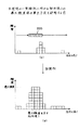
図16は、網点印刷法で1つのメッシュを用いて1つの色を印刷した場合に、画素ごとに輝度値が異なる理由を説明する図である。
図16(a)において、網点印刷法で1つの色を印刷する場合、印刷メッシュM1の格子点に配置された半径r1の塗りつぶし円D1を印刷することで行われる。そして、網点印刷法で印刷される色を変える場合、塗りつぶし円D1の半径r1を変化させる。このため、網点印刷法で1つの色が印刷された領域は、半径r1の塗りつぶし円D1が離散的に配置された領域になる。
FIG. 16 is a diagram for explaining the reason why the luminance value differs for each pixel when one color is printed using one mesh by the halftone printing method.
In FIG. 16A, when one color is printed by the halftone printing method, it is performed by printing a filled circle D1 having a radius r1 arranged at a lattice point of the printing mesh M1. When changing the color to be printed by the halftone printing method, the radius r1 of the filled circle D1 is changed. For this reason, the area where one color is printed by the halftone printing method is an area where the filled circles D1 having the radius r1 are discretely arranged.
図16(a)の印刷物をスキャナなどで読み取る場合、スキャナなどに固有の解像度で読み取りが行われる。このため、塗りつぶし円D1は、図16(b)に示すように、読み取りの際の解像度に対応した読み取りメッシュM2で区切られる画素ごとに読み取られる。ここで、塗りつぶし円D1は離散的に配置されているので、読み取りメッシュM2で区切られる画素に含まれる塗りつぶし円D1の面積が、全ての画素について均一にならない。この結果、図16(c)に示すように、真ん中の注目画素に対し、その周囲の8つの隣接画素P1〜P8の平均輝度が異なるようになる。 When the printed matter in FIG. 16A is read by a scanner or the like, reading is performed at a resolution unique to the scanner or the like. For this reason, as shown in FIG. 16B, the filled circle D1 is read for each pixel divided by the reading mesh M2 corresponding to the resolution at the time of reading. Here, since the filled circle D1 is discretely arranged, the area of the filled circle D1 included in the pixels delimited by the reading mesh M2 is not uniform for all the pixels. As a result, as shown in FIG. 16C, the average luminance of the eight neighboring pixels P1 to P8 around the center target pixel is different.
一方、図16(a)の印刷物から同一色の領域を抽出する場合、図16(a)の印刷物は網点印刷法で1つの色を表すものとして印刷されているので、図16(c)の真ん中の注目画素に対し、その周囲の8つの隣接画素P1〜P8は、注目画素と同一の色を表すものとして抽出する必要がある。このため、注目画素と各隣接画素P1〜P8との輝度差を求め、これらの輝度差の中の最大値(例えば、図16(c)の例では、注目画素と隣接画素P4との輝度差)を記録しておく。そして、入力画像から同一色の領域を抽出する場合、注目画素と隣接画素との間の輝度差の最大値をしきい値として、このしきい値以下の輝度差を有する隣接画素を注目画素と同一の色を表すものとして抽出する。 On the other hand, when the same color area is extracted from the printed material of FIG. 16A, the printed material of FIG. 16A is printed as one color by the halftone printing method, so FIG. For the target pixel in the middle, it is necessary to extract the eight neighboring pixels P1 to P8 around it to represent the same color as the target pixel. Therefore, the luminance difference between the target pixel and each of the adjacent pixels P1 to P8 is obtained, and the maximum value among these luminance differences (for example, in the example of FIG. 16C, the luminance difference between the target pixel and the adjacent pixel P4). ) Is recorded. When extracting the same color region from the input image, the maximum value of the luminance difference between the target pixel and the adjacent pixel is set as a threshold value, and the adjacent pixel having a luminance difference equal to or lower than the threshold value is set as the target pixel. Extracted to represent the same color.
以下、網点印刷法を忠実に再現したスキャナ読み取モデルの構築方法について説明する。
図17は、網点印刷法におけるスキャナ読み取りモデルを示す図である。
A method for constructing a scanner reading model that faithfully reproduces the halftone printing method will be described below.
FIG. 17 is a diagram illustrating a scanner reading model in the halftone printing method.
図17において、スキャナ読み取りモデルとして、シアン、マゼンタ、黄色の印刷メッシュM11、M12、M13を、それぞれ回転させて重ね合わせた印刷モデルを作る。ここで、シアン、マゼンタ、黄色の色の濃さを調節する場合、印刷メッシュM11、M12、M13の各格子点に配置される塗りつぶし円D11、D12、D13の大きさを調節する。 In FIG. 17, as a scanner reading model, cyan, magenta, and yellow printing meshes M11, M12, and M13 are rotated and overlapped to create a printing model. Here, when adjusting the densities of cyan, magenta, and yellow, the sizes of the filled circles D11, D12, and D13 arranged at the respective grid points of the print meshes M11, M12, and M13 are adjusted.
この時、一般的なスキャナ読み取りモデルのパラメータは、
・印刷メッシュM11、M12、M13の格子間隔md(ただし、格子間隔mdは、黄色、シアン、マゼンタ共通サイズ)
・黄色メッシュM11の水平線からの角度θ11
・マゼンタメッシュM12の水平線からの角度θ12
・シアンメッシュM13の水平線からの角度θ13
・黄色の塗りつぶし円D11の半径r11
・マゼンタの塗りつぶし円D12の半径r12
・シアンの塗りつぶし円D13の半径r13
であるが、本実施例では、この全てのパラメータを可変にすると煩雑すぎるので、ある程度の限定を与え、以下のように設定した。
At this time, the general scanner reading model parameters are:
-Grid spacing md of printing meshes M11, M12, and M13 (however, grid spacing md is a common size for yellow, cyan, and magenta)
・ An angle θ11 from the horizontal line of the yellow mesh M11
・ An angle θ12 from the horizontal line of the magenta mesh M12
-Angle θ13 from the horizontal line of cyan mesh M13
-Radius r11 of yellow filled circle D11
-Radius r12 of magenta fill circle D12
-Radius r13 of cyan filled circle D13
However, in this embodiment, it is too complicated to make all these parameters variable. Therefore, a certain degree of limitation is given and the following setting is made.
・黄色メッシュM11の水平線からの角度θ11=15度
・マゼンタメッシュM12の水平線からの角度θ12=30度
・シアンメッシュM13の水平線からの角度θ13 =45度
・格子間隔md=20ドット
この印刷モデルを使用して、シミュレーションを行い、黄色、マゼンタ、シアンの塗りつぶし円D11、D12、D13のそれぞれの半径r11、r12、r13に影響を受ける平均RGB値(Rm,Gm,Bm)を求める。具体的には、印刷メッシュM11、M12、M13の格子間隔mdよりもかなり大きな単位面積を考え、
Rm=255−単位面積中のシアンの面積×255/単位面積
Gm=255−単位面積中のマゼンタの面積×255/単位面積
Bm=255−単位面積中の黄色の面積×255/単位面積
として求める。
・ An angle from the horizontal line of the yellow mesh M11 = 15 degrees ・ An angle from the horizontal line of the magenta mesh M12 θ12 = 30 degrees ・ An angle from the horizontal line of the cyan mesh M13 θ13 = 45 degrees ・ Grid spacing md = 20 dots The simulation is performed to obtain the average RGB values (Rm, Gm, Bm) affected by the radii r11, r12, r13 of the yellow, magenta, and cyan filled circles D11, D12, D13. Specifically, considering a unit area that is considerably larger than the lattice spacing md of the printing meshes M11, M12, and M13,
Rm = 255—Cyan area in unit area × 255 / unit area Gm = 255—magenta area in unit area × 255 / unit area Bm = 255—yellow area in unit area × 255 / unit area .
次に、1つの色(Rm,Gm,Bm)で均一に印刷されている画像をスキャナで読み込んだ場合のスキャナ読み込みモデルについて考える。これは、印刷メッシュM11、M12、M13と独立な間隔sdを有する読み込みメッシュM14を導入し、この読み込みメッシュM14内のRGBの各輝度=各色の面積を求めることに相当する。 Next, consider a scanner reading model when an image that is uniformly printed with one color (Rm, Gm, Bm) is read by a scanner. This corresponds to introducing a read mesh M14 having an interval sd independent of the print meshes M11, M12, and M13, and obtaining each luminance of RGB = area of each color in the read mesh M14.
ここで、読み込みメッシュM14の間隔sdが、スキャナ読み込み解像度に相当する。なお、同じ平均色(Rm,Gm,Bm)の画像を読み込む場合でも、スキャナ読み込み解像度が大きい場合には、隣接画素のRGB輝度値は大きく異なり、逆にスキャナ読み込み解像度が小さい場合には、読み取った結果の画素はどの画素も平均色(Rm,Gm,Bm)に近づくため、隣接画素のRGB輝度差は0に近づくようになる。 Here, the interval sd of the reading mesh M14 corresponds to the scanner reading resolution. Even when images of the same average color (Rm, Gm, Bm) are read, if the scanner reading resolution is high, the RGB luminance values of adjacent pixels are greatly different, and conversely if the scanner reading resolution is low, the reading is performed. As a result, all the pixels approach the average color (Rm, Gm, Bm), so that the RGB luminance difference between the adjacent pixels approaches zero.
具体的な1つの読み込みメッシュM14内のRGB輝度値(Rc,Gc,Bc)は、以下のようになる。
Rc=255−読み込みメッシュ面積中のシアンの面積×255/読み込みメッシュ面積
Gc=255−読み込みメッシュ面積中のマゼンタの面積×255/読み込みメッシュ面積
Bc=255−読み込みメッシュ面積中の黄色の面積×255/読み込みメッシュ面積
間隔sdを変えた読み込みメッシュM14ごとにRGB輝度値(Rc,Gc,Bc)を求めておき、隣接画素とのRGBそれぞれの輝度差を求め、その中の適当な値(例えば、最大値)を色差テーブルに記録する。
The RGB luminance values (Rc, Gc, Bc) in one specific read mesh M14 are as follows.
Rc = 255 area of cyan in reading mesh area × 255 / reading mesh area Gc = 255—magenta area in reading mesh area × 255 / reading mesh area Bc = 255—yellow area in reading mesh area × 255 / Reading mesh area An RGB luminance value (Rc, Gc, Bc) is obtained for each reading mesh M14 in which the interval sd is changed, and an RGB luminance difference between adjacent pixels is obtained, and an appropriate value (for example, (Maximum value) is recorded in the color difference table.
この時、本来は、印刷モデルでは、印刷メッシュの交点に描かれた塗りつぶし円は、RGB相互に重なり合うので、RGBの各輝度値によって相互に影響がでて、RGB独立とは言えないが、このスキャナ読み込みモデルでは、単純化のために、RGBは相互に独立であるという仮説を立てた。 At this time, originally, in the printing model, the filled circles drawn at the intersections of the printing meshes overlap with each other, so that each RGB influences each other, and it cannot be said that RGB is independent. In the scanner reading model, for the sake of simplicity, we hypothesized that RGB are independent of each other.
従って、RGB輝度値、読み込み解像度、及び隣接画素の輝度差の結果が、RGB独立のテーブルに保存される。
図18は、Rのテーブルの例を示す図である。
Therefore, the RGB luminance value, the reading resolution, and the result of the luminance difference between adjacent pixels are stored in an RGB independent table.
FIG. 18 is a diagram illustrating an example of an R table.
図18において、R輝度値を0〜255まで変化させた場合について、スキャナ読み込み解像度が14〜35のそれぞれに対し、隣接画素との輝度差の最大値を求めている。ここで、R輝度値は3間隔で記録しているが、この間隔の間の値については、補間で求めることができる。 In FIG. 18, when the R luminance value is changed from 0 to 255, the maximum value of the luminance difference with the adjacent pixel is obtained for each of the scanner reading resolutions of 14 to 35. Here, although the R luminance value is recorded at three intervals, values between these intervals can be obtained by interpolation.
なお、図の例では、Rのテーブルの場合について示したが、G,Bのテーブルも同様である。このように、網点印刷法を模倣した印刷モデルを構築することにより、網点印刷法で生成される色をコンピュータ上で再現することが可能となり、網点印刷法で実際に印刷された印刷物を解析することなく、R,G,Bのテーブルを生成することが可能となる。 In the example shown in the figure, the case of the R table is shown, but the same applies to the G and B tables. In this way, by building a printing model that mimics the halftone printing method, it is possible to reproduce the colors generated by the halftone printing method on a computer, and the printed matter actually printed by the halftone printing method. R, G, B tables can be generated without analyzing.
R,G,Bのテーブルが与えられると、このR,G,Bのテーブルを参照することにより、入力画像から同一色の範囲を検出する際のしきい値を獲得することができる。
図19は、本発明の第実施例に係わる色差テーブル生成装置の構成を示すブロック図である。
Given an R, G, B table, a threshold for detecting the same color range from the input image can be obtained by referring to the R, G, B table.
FIG. 19 is a block diagram showing the configuration of the color difference table generating apparatus according to the first embodiment of the present invention.
図19において、111はカラー画像入力装置、112は外部出力装置、113はメモリ、114は演算装置(CPU)である。演算装置114には、印刷モデル生成部115及び色差テーブル生成部116が設けられ、印刷モデル生成部115は、図17に示した方法により印刷モデルを構築し、網点印刷法で生成される色をコンピュータ上で再現する。色差テーブル生成部116は、網点印刷法を模倣した印刷モデルに対し、スキャナ読み込みモデルを構築し、図18に示すような色差テーブルを、R,G,Bの各色について生成する。
In FIG. 19, 111 is a color image input device, 112 is an external output device, 113 is a memory, and 114 is an arithmetic unit (CPU). The
図20は、本発明の第7実施例に係わるパターン抽出装置の構成を示すブロック図である。
図20において、131はカラー画像入力装置、132は外部出力装置、133はメモリ、134は演算装置(CPU)である。演算装置134には、色差テーブル135、色分解画像生成部136及び文字領域抽出部137が設けられている。
FIG. 20 is a block diagram showing the configuration of a pattern extraction apparatus according to the seventh embodiment of the present invention.
In FIG. 20, 131 is a color image input device, 132 is an external output device, 133 is a memory, and 134 is an arithmetic unit (CPU). The
色差テーブル135は、例えば、図18に示すテーブルであり、RGBの各色ごとに、輝度値、読み込み解像度及び隣接画素の輝度差が格納されている。色分解画像生成部136は、入力画像の読み込み解像度及びRGB輝度値に基づいて色差テーブル135を検索し、入力画像の読み込み解像度及びRGB輝度値に対応した隣接画素の輝度差を取得する。そして、この隣接画素の輝度差をその隣接画素についてラベリングを行う際のしきい値とする。なお、入力画像の読み込み解像度及びRGB輝度値が異なると、隣接画素の輝度差も異なるので、入力画像のラベリングを行っている途中で、入力画像の読み込み解像度及びRGB輝度が変化した場合には、色差テーブル135を再度検索して、ラベリングを行う際のしきい値を更新する。
The color difference table 135 is, for example, a table shown in FIG. 18, and stores a luminance value, a reading resolution, and a luminance difference between adjacent pixels for each color of RGB. The color separation
注目画素の色(R,G,B)をキー情報として、色差テーブル135を検索し、RGB各色の同色と見なす隣接画素とのRGB各輝度差のしきい値が画素ごとに求まると、それを注目画素の周囲の画素に適応し、R,G,Bの各値とも隣接画素との輝度差がしきい値以内であれば、注目画素と隣接画素に同一ラベルを与える処理を行う。 The color difference table 135 is searched using the color (R, G, B) of the pixel of interest as key information, and when the threshold value of each RGB brightness difference with an adjacent pixel regarded as the same color of each RGB color is obtained for each pixel, If the luminance difference between the R, G, and B values and the adjacent pixel is within a threshold value, the process applies the same label to the target pixel and the adjacent pixel.
このラベリング処理では、隣り合う画素だけを対象にして、しかも画素の色に従ったしきい値を用いてラベリングを行うので、局所的に精密な色クラスタリングが可能となり、ラベル画像に穴が空いたり、輪郭がスムーズでなくなったりすることを防止できる。 In this labeling process, only adjacent pixels are targeted and labeling is performed using threshold values according to the color of the pixels, so that accurate local color clustering is possible, and there are holes in the label image. It is possible to prevent the contour from becoming unsmooth.
また、カラー文書画像から均一色の文字領域を高速、高精度に抽出することが可能となる。さらに、背景と物体の色が局所的に似ていて、画像全体では他の場所にも近い色がある画像に対しては、局所的に正確に同一色領域を抽出することが可能となる。 In addition, it is possible to extract a uniform color character region from a color document image at high speed and with high accuracy. Furthermore, for an image in which the background and the color of the object are locally similar and the entire image has colors close to other places, the same color region can be accurately extracted locally.
また、同一色とみなされる領域でも画素の色の値が周囲の色の値よりも多少かけ離れる場合においても、その部分が、領域内の穴や輪郭部分のデコボコとして誤って抽出されることを防止し、精度良く抽出することが可能となる。 In addition, even in a region that is considered to be the same color, even when the pixel color value is slightly different from the surrounding color value, that portion is erroneously extracted as a hole or contour portion in the region. It is possible to prevent and extract accurately.
ラベル画像が生成されると、入力画像のパターンの各ラベルごとに、各パターンについての外接矩形を生成する。そして、各外接矩形内の領域の色情報及び外接矩形の幾何学情報に基づいて、各外接矩形のグルーピングを行う。 When the label image is generated, a circumscribed rectangle for each pattern is generated for each label of the pattern of the input image. Then, each circumscribed rectangle is grouped based on the color information of the region in each circumscribed rectangle and the geometric information of the circumscribed rectangle.
文字領域抽出部137は、色分解画像生成部136でグルーピングされた外接矩形の配置状態や大きさなどを考慮して、原画像から求めたラベル画像の中から、文字列領域抽出を行う。
The character
例えば、カラー文書から大きな文字で記載されている見出しやタイトルなどのキーワードとなる文字の領域を抽出する場合、外接矩形の大きさや、外接矩形の並びの情報を使うことにより、見出しやタイトルなどのキーワードとなる文字列領域だけを抽出する。 For example, when extracting a character area that is a keyword such as a headline or title written in large characters from a color document, by using the size of the circumscribed rectangle and the information of the arrangement of the circumscribed rectangle, the headline, title, etc. Extract only the character string area that becomes the keyword.
図21は、図20のパターン抽出装置の動作を詳細に示すフローチャートである。
図21において、まず、画像入力処理を行う(ステップS11)。この画像入力処理では、CCDカメラやスキャナなどの撮像装置でカラー画像を入力し、メモリに保存する。
FIG. 21 is a flowchart showing in detail the operation of the pattern extraction apparatus of FIG.
In FIG. 21, first, an image input process is performed (step S11). In this image input process, a color image is input by an imaging device such as a CCD camera or a scanner and stored in a memory.
次に、モデル解像度推定処理を行う(ステップS12)。このモデル解像度推定処理では、カラー印刷のモアレを表現した印刷モデル及びスキャナ読み込みモデルから求めた色差テーブルに登録されている平均輝度及び隣接画素の輝度差の最大値を、入力画像から得られる平均輝度及び隣接画素の輝度差の最大値と比較し、入力画像全体を通して最も適合するスキャナ読み込み解像度を求める。 Next, model resolution estimation processing is performed (step S12). In this model resolution estimation process, the average luminance registered in the color difference table obtained from the printing model expressing the moiré of color printing and the scanner reading model and the maximum value of the luminance difference between adjacent pixels are obtained from the average luminance obtained from the input image. And the maximum value of the luminance difference between adjacent pixels, and obtain the most suitable scanner reading resolution throughout the entire input image.
図22は、本発明の一実施例に係わるモデル解像度推定処理を説明する図である。
図22において、入力画像141を3×3画素ずつのメッシュ142に分割し、分割された3×3画素a〜iの平均RGB輝度(Rm,Gm,Bm)と隣接画素の輝度差の最大値(Rd,Gd,Bd)を入力画像141全体について求める。ここで、3×3画素a〜iの隣接方向は20通りあるので、これらの20通り隣接画素の輝度差を求め、それらの輝度差のうち最大値(Rd,Gd,Bd)を採用する。
FIG. 22 is a diagram for explaining model resolution estimation processing according to an embodiment of the present invention.
In Figure 22, an input image is divided 141 into 3 × 3 pixels not a One
そして、この平均RGB輝度(Rm,Gm,Bm)と隣接画素の輝度差の最大値(Rd,Gd,Bd)をキー情報として色差テーブルを検索し、色差テーブルに登録されている平均輝度及び隣接画素の輝度差の最大値と最も適合するスキャナ読み込み解像度を求める。そして、入力画像141から求めた隣接画素の輝度差の最大値(Rd,Gd,Bd)と、色差テーブルに登録されている最も適合するスキャナ読み込み解像度での隣接画素の輝度差の最大値との差が所定の範囲内にない場合、その3×3画素a〜iに対してリジェクト符号(−1)を返し、それ以外は、適合符号(0)を返すようにする。
Then, the color difference table is searched using the average RGB luminance (Rm, Gm, Bm) and the maximum value (Rd, Gd, Bd) of the luminance difference between adjacent pixels as key information, and the average luminance and the adjacent luminance registered in the color difference table are searched. The scanner reading resolution that best matches the maximum value of pixel luminance difference is obtained. Then, the maximum value (Rd, Gd, Bd) of the luminance difference between adjacent pixels obtained from the
この処理を入力画像141全体について行うことにより、メッシュ142に分割された全ての3×3画素a〜iについて、リジェクト符号(−1)または適合符号(0)が付される。リジェクト符号(−1)または適合符号(0)が付された3×3画素a〜iのうち、適合符号(0)が付された3×3画素a〜iを対象として、これらについて求めたスキャナ読み込み解像度を平均し、この平均値を入力画像141全体のスキャナ読み込み解像度とする。
By performing this process on the
以下、RGB独立の処理であるので、Rを例にしてより具体的に説明する。
まず、Rテーブルの解像度値をある値に固定して、RテーブルのR輝度値をスキャンしていき、平均輝度値Rmが、Ri≦Rm<Ri+1となるR輝度値RiをRテーブルから検索する。この時、R輝度値Riに対する隣接画素との輝度値の最大値がRdi、R輝度値Ri+1に対する隣接画素との輝度値の最大値がRdi+1であるとすると、平均輝度値Rmが、R輝度値RiとR輝度値Ri+1との間の線形補間で表されるとして、その関係を隣接画素との輝度値の最大値にも適応して、推定される隣接画素との輝度値の最大値infered_deltaを求める。すなわち、
rl=Ri−Ri
rm=Rm−Ri
rn=Ri+1−Rm
infered_delta=Rri*rn/rl+Rri+1*rm/rl
である。
In the following, since the process is independent of RGB, the process will be described more specifically with R as an example.
First, the resolution value of the R table is fixed to a certain value, the R luminance value of the R table is scanned, and an R luminance value Ri in which the average luminance value Rm satisfies Ri ≦ Rm <Ri + 1 is searched from the R table. . At this time, assuming that the maximum value of the luminance value with the adjacent pixel for the R luminance value Ri is Rdi and the maximum value of the luminance value with the adjacent pixel for the R luminance value Ri + 1 is Rdi + 1, the average luminance value Rm is the R luminance value. Assuming that the relationship is expressed by linear interpolation between Ri and the R luminance value Ri + 1, the relationship is also applied to the maximum value of the luminance value with the adjacent pixel, and the estimated luminance value maximum_delta of the adjacent pixel is set to Ask. That is,
rl = Ri-Ri
rm = Rm−Ri
rn = Ri + 1−Rm
infered_delta = Rri * rn / rl + Rri + 1 * rm / rl
It is.
この推定される隣接画素との輝度値の最大値infered_deltaと実際に画像から求めた輝度値の最大値Rdとの差delta_rを、
delta_r=|Rd−infered_delta|
として求める。これと同様の処理をG,Bでも行い、delta_g,delta_bを求める。そして、その和deltaを、
delta=delta_r+delta_g+delta_b
として求める。
The difference delta_r between the estimated maximum brightness value delta_delta of the adjacent pixel and the maximum brightness value Rd actually obtained from the image is expressed as follows:
delta_r = | Rd-infused_delta |
Asking. The same processing is performed for G and B, and delta_g and delta_b are obtained. And the sum delta is
delta = delta_r + delta_g + delta_b
Asking.
解像度パラメータをスキャンして、このdeltaの値が最も小さくなる解像度resolと、その時のdeltaの値delta_minを求め、その値delta_minが、
delta_min>TH_SUB (TH_SUBは固定しきい値)
ならば、この3×3メッシュはモデルに適応しなかったとして、リジェクト符号(−1)を返し、それ以外は、適合符号(0)を返すようにする。そして、全入力画像の中の3×3メッシュの中で適合符号がついたメッシュだけを対象に、そのメッシュの解像度resolを平均し、この値を入力画像の解像度resolutionとする。
The resolution parameter is scanned to obtain the resolution resol having the smallest delta value and the delta value delta_min at that time. The value delta_min is
delta_min> TH_SUB (TH_SUB is a fixed threshold)
If this is the case, it is assumed that the 3 × 3 mesh has not been adapted to the model, and a reject code (−1) is returned. Otherwise, a matching code (0) is returned. Then, the resolution resolution of the mesh is averaged for only the mesh with the matching code among the 3 × 3 meshes in all the input images, and this value is set as the resolution resolution of the input image.
resolution=(Σ適合符号のメッシュのresol)
/適合符号のメッシュの数
なお、この解像度という言葉は、入力画像が実際にスキャナで読み込まれたときの解像度ではなく、この画像を予め用意したモデルに適合させたときのモデル上の読み取り解像度を表す。
resolution = (resolved mesh of Σ conforming code)
/ Number of meshes of conforming codes Note that the term resolution means not the resolution when the input image is actually read by the scanner, but the reading resolution on the model when this image is adapted to a model prepared in advance. To express.
次に、色ラベリング処理を行う(ステップS13)。この色ラベリング処理では、隣り合う画素の色が近い場合に同一ラベルを与え、ラベル画像と同一ラベルの連結領域の外接矩形を求める。外接矩形の情報には、外接矩形の座標値、外接矩形内の連結領域の平均色(R,G,B)、外接矩形内の連結領域のラベル番号、連結領域の面積(画素数)などを格納する。 Next, a color labeling process is performed (step S13). In this color labeling process, when the colors of adjacent pixels are close to each other, the same label is given, and a circumscribed rectangle of a connected area of the same label as the label image is obtained. The circumscribed rectangle information includes the coordinate value of the circumscribed rectangle, the average color (R, G, B) of the connected area in the circumscribed rectangle, the label number of the connected area in the circumscribed rectangle, the area (number of pixels) of the connected area, and the like. Store.
具体的には、入力画像の左上からラスタスキャンを行い、ラベル付けがされていない画素に注目する。この画素のRGB輝度値と推定解像度resolutionを用いて色差テーブルを検索し、隣接画素との輝度値の最大値をRGBそれぞれについて求める。隣接画素との輝度値の最大値が求まると、この隣接画素との輝度値の最大値を着目画素にラベル付けする際のしきい値とする。 Specifically, raster scanning is performed from the upper left of the input image, and attention is paid to pixels that are not labeled. The color difference table is searched using the RGB luminance value of this pixel and the estimated resolution resolution, and the maximum luminance value of the adjacent pixel is obtained for each of RGB. When the maximum value of the luminance value with the adjacent pixel is obtained, the maximum value of the luminance value with the adjacent pixel is used as a threshold value for labeling the pixel of interest.
このラベリング処理の時に、1画素から始まって次第に拡張していく同一ラベル領域に対して、1画素追加する度に、ラベル領域内の平均色(R,G,B)を求める。そして、このラベル領域と同一のラベルをこのラベル領域の周囲画素に付すかどうかを判断する時に、新たにラベル付けする周囲画素の色が、既にラベル付けされたラベル領域の平均色としきい値以上に離れている場合には、隣接画素間での色差がしきい値以内にあっても、新たにラベル付けする周囲画素に、既にラベル付けされたラベル領域と異なるラベルを付すようにする。この処理により、文字領域と背景領域の境界の次第に色が変化した場合でも、正しく文字領域を抽出することが可能となる。 At the time of this labeling process, the average color (R, G, B) in the label area is obtained every time one pixel is added to the same label area starting from one pixel and gradually expanding. When determining whether or not to attach the same label as the label area to the surrounding pixels of the label area, the color of the surrounding pixels to be newly labeled is equal to or greater than the average color of the already labeled label area and the threshold value. If the color difference between adjacent pixels is within the threshold value, the surrounding pixels to be newly labeled are attached with a label different from the already labeled label area. With this process, even when the color gradually changes at the boundary between the character area and the background area, the character area can be correctly extracted.
図23は、本発明の一実施例に係わる色ラベリング処理を説明する図である。
図23において、画素eの色が黒で、この画素eから遠ざかるに従って、色が黒から赤に徐々に変化しているものとする。そして、画素eと画素a〜d、f〜iは、画素eと画素a〜d、f〜iの色差がしきい値以内の場合は、画素eと画素a〜d、f〜iに対して同一のラベルが付される。
FIG. 23 is a diagram for explaining color labeling processing according to an embodiment of the present invention.
In FIG. 23, it is assumed that the color of the pixel e is black, and the color gradually changes from black to red as the distance from the pixel e increases. The pixel e and the pixels a to d and f to i are compared with the pixel e and the pixels a to d and f to i when the color difference between the pixel e and the pixels a to d and f to i is within a threshold value. Are given the same label.
次に、画素jのラベル付けを行う場合、画素fと画素jの色差がしきい値以内かどうかが判断されるとともに、画素a〜iの色の平均値と画素jの色の差がしきい値以内かどうかが判断される。そして、画素fと画素jの色差がしきい値以内であっても、画素a〜iの色の平均値と画素jの色の差がしきい値をこえる場合は、画素jには画素fと異なるラベルが付される。 Next, when labeling the pixel j, it is determined whether or not the color difference between the pixel f and the pixel j is within the threshold value, and the average value of the colors of the pixels a to i is compared with the color difference of the pixel j. It is determined whether it is within the threshold. Then, even if the color difference between the pixel f and the pixel j is within the threshold value, if the average value of the colors of the pixels a to i and the color difference of the pixel j exceed the threshold value, the pixel j has the pixel f A different label is attached.
ここで、画素eから遠ざかるに従って、色が徐々に変化している場合には、画素jの色と画素fの色は似ているけれども、画素jの色と画素eの色の違いは顕著になってくる。このため、既にラベル付けされている画素a〜iの色の平均値を画素jの色と比べると、画素a〜iの色の平均値には画素eの色の影響が反映されることから、画素fと画素jの色差に比べた場合に対し、色に差が大きくなる。 Here, when the color gradually changes as it moves away from the pixel e, the color of the pixel j and the color of the pixel f are similar, but the difference between the color of the pixel j and the color of the pixel e is significant. It becomes. For this reason, when the average value of the color of the pixels ai already labeled is compared with the color of the pixel j, the average value of the color of the pixels ai reflects the influence of the color of the pixel e. The color difference is larger than the color difference between the pixel f and the pixel j.
この結果、色が徐々に変化している場合においても、画素fと画素jとの間で境界を区切ることが可能となり、黒の領域と赤の領域に同一のラベルが付されることを防止できる。 As a result, even when the color changes gradually, it is possible to delimit the boundary between the pixel f and the pixel j, and the same label is prevented from being attached to the black area and the red area. it can.
以下、具体的な求め方を輝度値Rを例に取り説明する。
Rテーブルの解像度値を推定解像度に固定して、RテーブルのR輝度値をスキャンしていき、注目画素の輝度値Rが、Ri≦R<Ri+1となるR輝度値RiをRテーブルから検索する。この時、R輝度値Riに対する隣接画素との輝度値の最大値をRdi、R輝度値Ri+1に対する隣接画素との輝度値の最大値をRdi+1とすると、注目画素の輝度値Rが、RテーブルのR輝度値RiとRテーブルのR輝度値Ri+1の間の線形補間で表されるとして、その関係を隣接画素との輝度値の最大値にも適応して、推定される隣接画素との輝度値の最大値delta_rを求める。すなわち、
rl=Ri−Ri+1
rm=R−Ri
rn=Ri+1−R
delta_r=Rri*rn/rl+Rri+1*rm/rl
として求める。G,Bについても同様である。
Hereinafter, a specific calculation method will be described by taking the luminance value R as an example.
The resolution value of the R table is fixed to the estimated resolution, the R luminance value of the R table is scanned, and the R luminance value Ri in which the luminance value R of the pixel of interest satisfies Ri ≦ R <Ri + 1 is searched from the R table. . At this time, assuming that the maximum value of the luminance value of the adjacent pixel with respect to the R luminance value Ri is Rdi and the maximum value of the luminance value of the adjacent pixel with respect to the R luminance value Ri + 1 is Rdi + 1, the luminance value R of the target pixel is Assuming that the relationship between the R luminance value Ri and the R luminance value Ri + 1 of the R table is expressed by linear interpolation, the relationship is also applied to the maximum luminance value of the adjacent pixel, and the estimated luminance value of the adjacent pixel The maximum value delta_r is obtained. That is,
rl = Ri-
rm = R-Ri
rn = Ri + 1−R
delta_r = Rri * rn / rl + Rri + 1 * rm / rl
Asking. The same applies to G and B.
このようにして、未処理の注目画素の(R,G,B)値から隣接画素との輝度差の最大値(delta_r,delta_g,delta_b)を求め、この隣接画素との輝度差の最大値(delta_r,delta_g,delta_b)をラベリング時のしきい値とする。 In this manner, the maximum value of the luminance difference (delta_r, delta_g, delta_b) from the adjacent pixel is obtained from the (R, G, B) value of the unprocessed target pixel, and the maximum value of the luminance difference from this adjacent pixel ( delta_r, delta_g, and delta_b) are threshold values for labeling.
次に、この未処理の注目画素の周囲8画素を走査して、注目画素の周囲に既にラベル付けされた画素があり、その既にラベル付けされた画素のRGB輝度値(Rs,Gs,Bs)が、
|R−Rs|<=delta_r
かつ
|G−Gs|<=delta_g
かつ
|B−Bs|<=delta_b
の場合に、注目画素は、その周囲画素と近い色であるので、周囲画素のラベルをカレントラベルregionとして保存し、注目画素のラベルとしてカレントラベルregionを与える。また、同時に、カレントラベルregionが与えられている領域の平均色(Rm,Gm,Bm)として、周囲のラベルの平均色に注目画素の色を加味した新たな平均色を求める。
Next, 8 pixels around the unprocessed pixel of interest are scanned, and there are pixels already labeled around the pixel of interest, and the RGB luminance values (Rs, Gs, Bs) of the already labeled pixels But,
| R−Rs | <= delta_r
And | G-Gs | <= delta_g
And | B-Bs | <= delta_b
In this case, since the target pixel has a color close to the surrounding pixels, the label of the surrounding pixel is stored as the current label region, and the current label region is given as the label of the target pixel. At the same time, a new average color obtained by adding the color of the pixel of interest to the average color of the surrounding labels is obtained as the average color (Rm, Gm, Bm) of the region to which the current label region is given.
それ以外の場合は、カレントラベルとして、今まで付けたラベル値+1のラベル値を設定し、注目画素のラベルにもそのラベル値を付与する。この場合でも、領域の平均色(Rm,Gm,Bm)として、注目画素のRGB値を設定する。 In other cases, the label value of the label value + 1 added so far is set as the current label, and the label value is also given to the label of the target pixel. Even in this case, the RGB value of the target pixel is set as the average color (Rm, Gm, Bm) of the region.
どちらの場合でも、注目画素の座標値を処理対象座標配列に保存する。
次に、注目画素の周りに同色領域を拡張する処理を行う。この処理では、処理対象座標配列の中から、先頭の座標値を取り出し、その座標の画素を注目画素とする。注目画素のRGB輝度値からRGB各色の隣接画素の輝度値の差の推定しきい値(delta_r,delta_g,delta_b)を求める。
In either case, the coordinate value of the target pixel is stored in the processing target coordinate array.
Next, a process of expanding the same color area around the target pixel is performed. In this process, the first coordinate value is extracted from the processing target coordinate array, and the pixel at that coordinate is set as the target pixel. Estimated threshold values (delta_r, delta_g, delta_b) of differences in luminance values of adjacent pixels of each RGB color are obtained from the RGB luminance values of the target pixel.
また、これまでのこの領域の平均色の(Rm,Gm,Bm)値と推定解像度から平均色の各RGBの輝度差のしきい値(delta_rm,elta_gm,elta_bm)を求める。 Further, the threshold value (delta_rm, elta_gm, elta_bm) of the luminance difference of each RGB of the average color is obtained from the average color (Rm, Gm, Bm) value of this area and the estimated resolution.
次に、図10(a)に示すように、注目画素の周囲8画素を走査して、注目画素の周囲の各画素の(Ri,Gi,Bi)値(i=1〜8)を求め、注目画素の(Rc,Gc,Bc)値や平均色の(Rm,Gm,Bm)値とのRGB各色の輝度差を求め、それが、
|Ri−Rc|<=delta_r
かつ
|Gi−Gc|<=delta_g
かつ
|Bi−Bc|<=delta_b
|Ri−Rm|<=delta_rm
かつ
|Gi−Gm|<=delta_gm
かつ
|Bi−Bm|<=delta_bm
の場合に、注目画素と同一ラベルを付け、周囲画素の座標を処理対象座標配列に追加する。今処理した注目画素は、処理対象座標配列から削除する。
Next, as shown in FIG. 10A, the surrounding eight pixels of the target pixel are scanned to obtain the (Ri, Gi, Bi) values (i = 1 to 8) of the respective pixels around the target pixel. The luminance difference of each RGB color from the (Rc, Gc, Bc) value of the target pixel and the (Rm, Gm, Bm) value of the average color is obtained,
| Ri-Rc | <= delta_r
And | Gi-Gc | <= delta_g
And | Bi-Bc | <= delta_b
| Ri-Rm | <= delta_rm
And | Gi-Gm | <= delta_gm
And | Bi-Bm | <= delta_bm
In this case, the same label as the target pixel is attached, and the coordinates of the surrounding pixels are added to the processing target coordinate array. The pixel of interest that has just been processed is deleted from the processing target coordinate array.
次に、処理座標のx,yの最大値、最小値を求め、それをこのラベル領域の外接矩形として保存する。また、このラベル領域の平均色を外接矩形の属性として保存する。
この処理を処理対象配列の内容がなくなるまで続ける。
Next, the maximum and minimum values of x and y of the processing coordinates are obtained, and stored as circumscribed rectangles of this label area. The average color of the label area is stored as a circumscribed rectangle attribute.
This process is continued until the content of the processing target array is exhausted.
ラベリングの結果、ラベル画像(同一領域は、同じラベル値が付与されている画像)と同じラベルを持つ領域を囲む外接矩形が獲得される。
また、ラベリング処理の出力情報として、以下のデータが出力される。
As a result of the labeling, a circumscribed rectangle surrounding the area having the same label as the label image (the same area has the same label value) is acquired.
In addition, the following data is output as output information of the labeling process.
・ラベル画像:4バイト/1画素
・外接矩形
矩形数 :maxcount
矩形情報:1btbl
内包するラベル画像のラベル番号:label
矩形左上座標 :(xmin,ymin)
矩形右下座標 :(xmax,ymax)
矩形内の代表色 :(r,g,b)
所属するグループ番号 :string_label
輪郭長 :contour
次に、注目矩形抽出処理を行う(ステップS14)。この注目矩形抽出処理では、全ての色の外接矩形を対象にして、ある事前に決めた範囲に入るサイズの外接矩形を注目矩形として抽出する。
-Label image: 4 bytes / pixel-circumscribed rectangle Number of rectangles: maxcount
Rectangle information: 1 btbl
Label number of the label image to be included: label
Rectangular upper left coordinate: (xmin, ymin)
Rectangular lower right coordinates: (xmax, ymax)
Representative color in rectangle: (r, g, b)
Affiliated group number: string_label
Contour length: control
Next, a target rectangle extraction process is performed (step S14). In this attention rectangle extraction process, a circumscribed rectangle having a size that falls within a predetermined range is extracted as a target rectangle for all color circumscribed rectangles.
具体的には、x方向長さが23dot(100dpi時)以上、画像の幅の1/2以下、かつ、y方向長さが23dot(100dpi時)以上、画像の高さの1/2以下の外接矩形を注目矩形として抽出する。 Specifically, the x-direction length is 23 dots (at 100 dpi) or more and 1/2 or less of the image width, and the y-direction length is 23 dots (at 100 dpi or more) and the image height is 1/2 or less. A circumscribed rectangle is extracted as a target rectangle.
この注目矩形抽出処理により、外接矩形同士をグルーピングする際の基準となる外接矩形の大きさを限定することが可能となり、例えば、タイトル領域を抽出する場合に、タイトルとなる文字の大きさに適合した外接矩形を基準として、外接矩形同士をグルーピングすることが可能となり、ノイズや背景などのタイトルには含まれない外接矩形が基準とされて、グルーピング処理が行われることを防止することが可能となることから、不要な処理を省略して、処理速度を向上させることが可能となる。 With this attention rectangle extraction process, it becomes possible to limit the size of the circumscribed rectangle that becomes the reference when grouping the circumscribed rectangles. For example, when extracting the title area, it matches the size of the title character It is possible to group the circumscribed rectangles based on the circumscribed rectangle, and to prevent the grouping process from being performed based on the circumscribed rectangle that is not included in the title such as noise or background. Therefore, unnecessary processing can be omitted and the processing speed can be improved.
次に、注目矩形の周りの探索範囲とそこにかかる矩形抽出を行う(ステップS15)。この探索範囲にかかる矩形抽出処理では、注目矩形の周囲に、あるサイズの探索範囲を設定し、その範囲にかかる矩形を抽出する。 Next, the search range around the target rectangle and the extraction of the rectangle related thereto are performed (step S15). In the rectangle extraction process for the search range, a search range of a certain size is set around the rectangle of interest, and a rectangle for the range is extracted.
図24は、本発明の一実施例に係わる注目矩形の周囲の探索範囲の設定方法を説明する図である。
図24において、矩形番号1〜30の外接矩形が抽出され、矩形番号1の外接矩形151を注目矩形としたものとする。そして、この外接矩形151の周りに探索範囲152が設定されたものとすると、外接矩形151についてのグルーピングの処理対象として、探索範囲152にかかる矩形番号2〜24の外接矩形のみを選択し、探索範囲152にかからない矩形番号25〜30の外接矩形については、外接矩形151のグルーピングの処理対象としない。
FIG. 24 is a diagram for explaining a method for setting a search range around a target rectangle according to an embodiment of the present invention.
In FIG. 24, the circumscribed rectangles having the
このように、外接矩形同士をグルーピングする際に、外接矩形の探索範囲を注目矩形の周りに限定することにより、所定の範囲内にまとまって存在している文字列のみを抽出することが可能となり、例えば、タイトル領域を抽出する場合に、タイトルには含まれないような離れた位置に存在する文字を考慮する必要がなくなることから、タイトル領域の抽出を効率的に行うことが可能となる。 In this way, when grouping circumscribed rectangles, by limiting the search range of the circumscribed rectangles around the target rectangle, it is possible to extract only the character strings that exist together within the predetermined range. For example, when a title area is extracted, it is not necessary to consider characters existing at a distant position that are not included in the title, so that the title area can be extracted efficiently.
具体的には、探索範囲152は、注目矩形151の縦横の長さの内、長い方をlenとして、lenと100dpiで35dotの小さい方を注目矩形の周囲の探索範囲長range_sizeとして求める。
Specifically, the
注目矩形の周囲range_sizeの範囲にかかる外接矩形を高速に求めるため、以下の方法を用いる。
図25は、本発明の一実施例に係わる注目矩形の周囲の探索範囲にかかる矩形の抽出方法を説明する図である。
The following method is used to obtain a circumscribed rectangle in the range of the range_size around the target rectangle at high speed.
FIG. 25 is a diagram illustrating a method for extracting a rectangle related to a search range around a target rectangle according to an embodiment of the present invention.
図25において、矩形番号1〜4の外接矩形161〜164が抽出されたものとすると、XYの各座標値に存在する矩形番号及び矩形数を求め、これらの矩形番号及び矩形数をXYの各座標値ごとに登録する。
In FIG. 25, if the circumscribed
例えば、X座標値1〜4の位置には外接矩形161〜164が存在しないので、矩形数n=0、矩形番号=空が登録され、X座標値5〜13の位置には矩形番号4の外接矩形164が存在しているので、矩形数n=1、矩形番号=4が登録され、X座標値14の位置には矩形番号3の外接矩形163及び矩形番号4の外接矩形164が存在しているので、矩形数n=2、矩形番号=3、4が登録され、X座標値15、16の位置には矩形番号4の外接矩形164が存在しているので、矩形数n=1、矩形番号=4が登録される。以下、同様である。
For example, since the circumscribed
次に、矩形番号3の外接矩形163を注目矩形とし、この外接矩形163の周りに探索範囲165が設定されたものとすると、この探索範囲165に含まれるXYの各座標値を求める。そして、XYの各座標値の矩形番号をXYそれぞれについて求め、XYの両方に含まれる矩形番号を探索範囲165にかかる外接矩形とする。例えば、探索範囲165のX座標に含まれる外接矩形の矩形番号は2〜4、探索範囲165のY座標に含まれる外接矩形の矩形番号は1〜4であるので、XYの両方に含まれる矩形番号は2〜4となる。この結果、探索範囲165にかかる外接矩形として、矩形番号2〜4に対応する外接矩形162〜164が得られる。
Next, assuming that the circumscribed
具体的には、以下のa)〜d)の処理を行う。
a)画像全体のX,Y軸へ矩形番号を投影する。
画像全体のX,Y軸の1画素毎に、それに属する矩形数と矩形番号の集合を登録する。例えば、矩形番号iがX軸の(x1,x2)の範囲にあるとすれば、X軸のx1からx2の座標には、番号iが矩形番号の集合に入ることになる。同じことを全矩形について縦横座標について行う。
Specifically, the following processes a) to d) are performed.
a) A rectangular number is projected onto the X and Y axes of the entire image.
For each pixel on the X and Y axes of the entire image, a set of the number of rectangles and rectangle numbers belonging to it is registered. For example, if the rectangle number i is in the range of (x1, x2) on the X axis, the number i enters the set of rectangle numbers at the coordinates of x1 to x2 on the X axis. The same is done for the ordinate and abscissa for all rectangles.
b)注目矩形の周囲にrange_sizeの範囲を設定する。
c)range_sizeの範囲のX軸の座標毎の矩形種類を論理ORして矩形番号の集合を抽出する。
b) A range of range_size is set around the target rectangle.
c) A set of rectangle numbers is extracted by logically ORing the rectangle types for each coordinate of the X axis in the range of range_size.
同様にY軸でも抽出する。
d)X軸から求めた矩形番号の集合と、Y軸から求めた矩形番号の集合を論理ANDして、この注目矩形の周囲にある矩形集合を決定する。
Similarly, the Y axis is extracted.
d) The set of rectangle numbers obtained from the X axis and the set of rectangle numbers obtained from the Y axis are logically ANDed to determine a set of rectangles around the target rectangle.
なお、図5の矩形番号の格納方法では、画像全体に存在する全ての矩形番号を格納する容量が各座標値ごとに必要となり、記憶容量が大きくなる。そこで、上述した座標毎の矩形数及び矩形番号を高速に、かつ必要メモリを最小に求めるために、以下のような方式をとる。 In the rectangular number storage method of FIG. 5, a capacity for storing all the rectangular numbers existing in the entire image is required for each coordinate value, and the storage capacity is increased. Therefore, in order to obtain the number of rectangles and the rectangle number for each coordinate described above at a high speed and to minimize the necessary memory, the following method is adopted.
図26は、本発明の一実施例に係わる注目矩形の周囲の探索範囲にかかる矩形情報の格納方法を説明する図である。
図26(a)において、矩形番号1、2の外接矩形171、172が抽出されたものとし、外接矩形171はX座標が155〜165の範囲内にあり、外接矩形172はX座標が160〜163の範囲内にあるものとする。このため、図26(b)に示すように、外接矩形171については、X座標が155〜165の位置に矩形番号1が登録され、外接矩形172については、X座標が160〜163の位置に矩形番号2が登録される。
FIG. 26 is a diagram illustrating a method for storing rectangle information relating to the search range around the target rectangle according to an embodiment of the present invention.
In FIG. 26A, it is assumed that circumscribed
次に、図26(c)に示すように、抽出された矩形番号1、2を、X座標155〜165の順序で矩形番号1、2順に並べ換え、X座標値が同じ値を示す矩形番号が幾つあるかを数えることにより、各座標値の矩形数を求めることができる。
Next, as shown in FIG. 26C, the extracted
具体的には、以下のi)〜v)の処理を行う。
i)全ての矩形の横幅を合計して、その長さの数だけ矩形番号、座標の情報を持ったデータ構造を用意する。
Specifically, the following processes i) to v) are performed.
i) The widths of all rectangles are totaled, and a data structure having rectangle number and coordinate information corresponding to the length is prepared.
ii)矩形の座標と矩形番号を用意されたデータ構造のデータにセットする。
iii)このデータ構造のデータを座標値でソートする。
iv) データの座標値を順にみていき、座標値が同じものの数を座標値毎に数え、それをその座標に属する矩形数とする。また、その座標毎の矩形数分だけ矩形番号を入れる記録領域を確保する。ソートしたデータ構造を先頭からスキャンしていき、座標が同じ間は数をカウントしていき、座標値が変わったところで数を確定させ、それを保存する。
ii) Set the coordinates of the rectangle and the rectangle number to the data of the prepared data structure.
iii) Sort data of this data structure by coordinate values.
iv) The coordinate values of the data are examined in order, the number of the same coordinate values is counted for each coordinate value, and this is the number of rectangles belonging to the coordinates. In addition, a recording area is provided in which rectangle numbers are entered by the number of rectangles for each coordinate. The sorted data structure is scanned from the top, and the number is counted while the coordinates are the same. When the coordinate value changes, the number is fixed and saved.
v)ソートしたデータ構造で、座標値が同じ物の矩形番号を上で確保した領域に格納する。これもソートしたデータ構造を先頭からスキャンしていき、座標が同じ間は、矩形番号を格納領域にセットする。 v) Store the rectangular numbers of the objects with the same coordinate value in the sorted data structure in the area secured above. This also scans the sorted data structure from the top, and sets the rectangle number in the storage area while the coordinates are the same.
次に、同色グループ抽出処理を行う(ステップS16)。この同色グループ抽出では、1つの注目矩形に注目して、その注目矩形内のパターンの平均色からラベリングの時と同様にRGB各色の輝度差のしきい値を求める。注目矩形の探索範囲にかかっている外接矩形の中で、注目矩形とのRGB輝度差が、しきい値以内のものを同一グループとして抽出し、グループ情報領域に格納する。さらに、新たにグループに追加された外接矩形を基準にして同様の処理を行い、グループに追加矩形が無くなるまで繰り返し処理する。 Next, the same color group extraction process is performed (step S16). In this same color group extraction, attention is paid to one target rectangle, and the threshold value of the luminance difference of each RGB color is obtained from the average color of the pattern in the target rectangle as in the case of labeling. Among circumscribed rectangles that cover the search range of the target rectangle, those having an RGB luminance difference within the threshold value with respect to the target rectangle are extracted as the same group and stored in the group information area. Further, the same processing is performed on the basis of the circumscribed rectangle newly added to the group, and the processing is repeated until there is no additional rectangle in the group.
具体的には、1つの注目矩形の値(Rc,Gc,Bc)とその周囲矩形の集合の中の1つの外接矩形iの値(Ri,Gi,Bi)のRGB空間上の距離を以下のように定義する。 Specifically, the distance in the RGB space between the value (Rc, Gc, Bc) of one rectangle of interest and the value (Ri, Gi, Bi) of one circumscribed rectangle i in the set of surrounding rectangles is expressed as follows: Define as follows.
dist=|Rc−Ri|+|Gc−Gi|+|Bc−Bi|
また、注目矩形の値(Rc,Gc,Bc)と解像度resolutionから求められるRGBの各輝度差をdelta_r,delta_g,delta_bとする。注目矩形の値(Rc,Gc,Bc)とその周囲の外接矩形の集合の中の1つの外接矩形iの値(Ri,Gi,Bi)が以下の条件を満足するとき、注目矩形の周囲の外接矩形は、注目矩形のグループに属すると判定して、周囲の外接矩形iを注目矩形のグループに格納する。
dist = | Rc-Ri | + | Gc-Gi | + | Bc-Bi |
Further, the luminance differences of RGB obtained from the value of the target rectangle (Rc, Gc, Bc) and the resolution resolution are delta_r, delta_g, and delta_b. When the value of the rectangle of interest (Rc, Gc, Bc) and the value of one circumscribed rectangle i (Ri, Gi, Bi) in the surrounding circumscribed rectangle set satisfy the following conditions, The circumscribed rectangle is determined to belong to the target rectangle group, and the surrounding circumscribed rectangle i is stored in the target rectangle group.
dist<TH_RGB (TH_RGB=20)
または
(|Rc−Ri|<delta_r
かつ
|Gc−Gi|<delta_g
かつ
|Bc−Bi|<delta_b)
また、同時に、この新たにグループに加わった矩形番号を新規追加矩形領域に格納しておく。
dist <TH_RGB (TH_RGB = 20)
Or (| Rc-Ri | <delta_r
And | Gc-Gi | <delta_g
And | Bc-Bi | <delta_b)
At the same time, the rectangle number newly added to the group is stored in the newly added rectangle area.
次に、新規追加矩形領域の先頭の矩形番号を取り出し、それを新たな注目矩形として、その周囲にある外接矩形を求め、上の手順を繰り返して、グループに属する外接矩形を求める。この手順をグループに新たに加わる矩形が無くなるまで繰り返す。 Next, the top rectangle number of the newly added rectangle area is taken out, and a circumscribed rectangle around it is obtained as a new attention rectangle, and the above procedure is repeated to obtain a circumscribed rectangle belonging to the group. This procedure is repeated until there are no more rectangles added to the group.
以上の処理により、以下の抽出するグループ情報のデータ構造が得られる。
グループ内の矩形数 :num
グループを構成する矩形番号 :child
重なり矩形統合後の矩形数 :overlap_num
重なり矩形統合後の矩形情報 :overlap
(データタイプは、矩形情報1btb1型)
グループ内文字列の方向コード:orient
グループ内の文字列数 :gyou_num文字列の矩形情報 :gyou
次に、グループ内平均文字線太さ抽出処理を行う(ステップS17)。このグループ内平均文字線太さ抽出処理では、グループ内の外接矩形に対応するラベル画像のパターンに対して、輪郭追跡処理を行い、輪郭長を求める。すなわち、グループに属する1つの外接矩形の矩形範囲内で、その外接矩形のラベル番号に注目して、ラベル画像上で、輪郭追跡処理を行う。抽出した輪郭の長さを、その矩形の輪郭長の属性にセットする。そして、そのパターンの面積を輪郭長で割って、文字の線の平均的な太さを求め、その値を矩形の属性として矩形情報に登録する。
Through the above processing, the data structure of the group information to be extracted is obtained.
Number of rectangles in group: num
Rectangle number that constitutes a group: child
Number of rectangles after overlapping rectangles integrated: overlap_num
Rectangle information after overlapping rectangle integration: overlap
(Data type is rectangular information 1btb1 type)
Direction code of character string in group: orient
Number of character strings in group: rectangle information of gyou_num character string: gyou
Next, in-group average character line thickness extraction processing is performed (step S17). In this intra-group average character line thickness extraction process, the outline tracking process is performed on the pattern of the label image corresponding to the circumscribed rectangle in the group to obtain the outline length. That is, the contour tracking process is performed on the label image while paying attention to the label number of the circumscribed rectangle within the range of one circumscribed rectangle belonging to the group. The length of the extracted contour is set in the contour length attribute of the rectangle. Then, the area of the pattern is divided by the contour length to obtain the average thickness of the character line, and the value is registered in the rectangle information as a rectangle attribute.
図27は、本発明の一実施例に係わる文字線の太さの算出方法を説明する図である。
図27(a)において、例えば、「フ」というパターンが抽出されたものとすると、「フ」というパターンに含まれる画素数を数えることにより、「フ」というパターンの面積Sを算出する。
FIG. 27 is a diagram for explaining a method for calculating the thickness of a character line according to an embodiment of the present invention.
In FIG. 27A, for example, if a pattern “F” is extracted, the area S of the pattern “F” is calculated by counting the number of pixels included in the pattern “F”.
次に、図27(b)に示すように、「フ」というパターンの輪郭を抽出し、この輪郭長Lを算出する。そして、「フ」というパターンの面積Sを輪郭長Lで割って、「フ」というパターンの平均的な太さWを求める。 Next, as shown in FIG. 27B, the contour of the pattern “F” is extracted, and this contour length L is calculated. Then, the area S of the pattern “F” is divided by the contour length L to obtain the average thickness W of the pattern “F”.
次に、文字線太さによる再グループ化処理を行う(ステップS18)。この再グループ化処理では、グループ内の外接矩形を対象に、外接矩形の平均文字線太さを用いて、グループ化を行い、新たなグループ情報を構築する。すなわち、グループ内の外接矩形を対象にして、図21のステップS14〜S16の処理を繰り返す。ここで、ステップS16のグループ化の時に、ステップS15で使用した色情報だけでなく、推定文字線太さ(=矩形内のパターン面積/パターンの輪郭長)も使用する。 Next, a regrouping process based on the character line thickness is performed (step S18). In this regrouping process, grouping is performed on the circumscribed rectangle in the group using the average character line thickness of the circumscribed rectangle, and new group information is constructed. That is, the enclosing rectangles in the group object, returns Ri Repetitive processes in steps S14~S16 in FIG. Here, at the time of grouping in step S16, not only the color information used in step S15 but also the estimated character line thickness (= pattern area in the rectangle / pattern contour length) is used.
図28は、本発明の一実施例に係わる文字線の太さによる再グルーピング処理を説明する図である。
図28において、「グループ1」という文字列と「グループ2」という文字列が同一色で記述され、互いに近接して配置されているため、「グループ1」という文字列と「グループ2」という文字列が同一のグループ181にグルーピングされたものとする。
FIG. 28 is a diagram for explaining re-grouping processing based on character line thickness according to an embodiment of the present invention.
In FIG. 28, since the character string “
ここで、「グループ1」という文字列に含まれる文字の太さと「グループ2」という文字列に含まれる文字の太さを算出し、異なる太さの文字を別々のグループに分割する。この結果、「グループ1」という文字列はグループ182にグルーピングされ、「グループ2」という文字列はグループ183にグルーピングされる。
Here, the thickness of the character included in the character string “
この処理により、元のグループで背景などの文字パターンと同色のものがあり、背景と文字パターンが同じグループに属していたものを、別々のグループにしたり、文字パターンだけのグループでもフォントやサイズが異なるものを別々のグループにしたりすることができる。 With this process, the original group has the same color as the background and other character patterns, and the background and character patterns belong to the same group. Different things can be in separate groups.
具体的には、2つの外接矩形のうち、第1の外接矩形の推定文字線太さthick1及び第2の外接矩形の推定文字線太さthick2から、文字線太さの比thick_rateを以下のように求める。 Specifically, of the two circumscribed rectangles, the character line thickness ratio thick_rate is calculated from the estimated character line thickness thick1 of the first circumscribed rectangle and the estimated character line thickness thick2 of the second circumscribed rectangle as follows: Ask for.
thick_rate=max(thick1,thick2)
/min(thick1,thick2)
そして、図21のステップS15と同じように、以下の条件を満足した時に、2つの外接矩形を同じグループとして記録する。
thick_rate = max (thick1, thick2)
/ Min (thick1, thick2)
Then, as in step S15 in FIG. 21, two circumscribed rectangles are recorded as the same group when the following conditions are satisfied.
thick_rate<TH_THICK_RATE
かつ
(dist<TH_RGB
または
(|Rc−Ri|<delta_r
かつ
|Gc−Gi|<delta_g
かつ
|Bc−Bi|<delta_b))
ただし、TH_THICK_RATEは、2.5と設定している。
thick_rate <TH_THICK_RATE
And (dist <TH_RGB
Or (| Rc-Ri | <delta_r
And | Gc-Gi | <delta_g
And | Bc-Bi | <delta_b))
However, TH_THICK_RATE is set to 2.5.
この処理を元のグループ内全ての外接矩形について行い、グループ内の新たなグルーピングを行う。
文字線太さを求める場合、パターンの輪郭を求める必要があるが、輪郭追跡を高速化するため、以下の処理を行う。
This process is performed for all circumscribed rectangles in the original group, and a new grouping in the group is performed.
When obtaining the thickness of the character line, it is necessary to obtain the contour of the pattern, but the following processing is performed in order to speed up the contour tracking.
図29は、本発明の一実施例に係わる輪郭追跡における画素の探索開始点の設定方法を説明する図である。
図29(a)において、画素a〜iで構成されるパターンの輪郭を求めるものとすると、ラベル画像の左上からラスタスキャンを行うことにより、画素aが見つかる。画素aが見つかると、画素aに隣接する8つの画素のうち、画素aの直前に探索された画素の次の画素a’を探索開始点として、画素aに隣接する画素を時計回りに探索する。そして、画素eが見つかると、図29(b)に示すように、画素eに隣接する8つの画素のうち、画素eの直前に輪郭として探索された画素aの次の画素e’を探索開始点として、画素eに隣接する画素を時計回りに探索する。そして、画素iが見つかると、図29(c)に示すように、画素iに隣接する8つの画素のうち、画素iの直前に輪郭として探索された画素eの次の画素i’を探索開始点として、画素iに隣接する画素を時計回りに探索する。以下、同様にして、図29(d)に示すように、画素a→画素e→画素i→画素h→画素g→画素f→画素b→画素cが画素a〜iで構成されるパターンの輪郭として抽出される。
FIG. 29 is a diagram for explaining a pixel search start point setting method in contour tracking according to an embodiment of the present invention.
In FIG. 29A, assuming that the contour of a pattern composed of pixels a to i is to be obtained, pixel a is found by performing a raster scan from the upper left of the label image. When the pixel a is found, the pixel adjacent to the pixel a is searched clockwise with the pixel a ′ next to the pixel searched immediately before the pixel a among the eight pixels adjacent to the pixel a as a search start point. . When the pixel e is found, as shown in FIG. 29 (b), the search is started for the pixel e ′ next to the pixel a searched for as an outline immediately before the pixel e among the eight pixels adjacent to the pixel e. As a point, a pixel adjacent to the pixel e is searched clockwise. When the pixel i is found, as shown in FIG. 29C, the search for the pixel i ′ next to the pixel e searched for as a contour immediately before the pixel i is started from the eight pixels adjacent to the pixel i. As a point, a pixel adjacent to the pixel i is searched clockwise. Hereinafter, similarly, as shown in FIG. 29D, a pattern in which pixel a → pixel e → pixel i → pixel h → pixel g → pixel f → pixel b → pixel c is composed of pixels a to i is formed. Extracted as a contour.
具体的には、以下のa)〜f)の処理が行われる。
a)矩形サイズの処理済みフラグを用意し、初期値として、全て未処理フラグとして0をセットする。
Specifically, the following processes a) to f) are performed.
a) A rectangular size processed flag is prepared, and 0 is set as an unprocessed flag as an initial value.
b)矩形範囲内を処理済みフラグとラベル画像で同時に左上からラスタスキャンして、処理済みフラグが0で、かつラベル番号がカレント矩形のラベル番号である画素iを探す。輪郭長を0と設定する。 b) a raster scan from upper left simultaneously processed flag and label image within the rectangular range, in processing rhythmic flag is 0 and label number looks for pixel i is a current rectangle label number. Set the contour length to zero.
c)画素iから周囲の8画素を図30の0から順番に時計回りに探索し、処理済みフラグが0で、かつラベル番号がカレント矩形のラベル番号である画素がある場合には、その画素の方向コードDCを抽出する。 searched clockwise from c) pixel i in order to 8 pixels around 0 of FIG. 30, when in processing rhythmic flag is 0 and label number is a pixel a label number of current rectangle, the A pixel direction code DC is extracted.
図30は、本発明の一実施例に係わるカレント画素からみた方向コードを示す図である。
図30において、Cはカレント画素、0〜7はカレント画素からみた周囲画素で、Cからみた方向コードDCである。画素iから周囲の8画素を探索する場合、この順番で探索する。
FIG. 30 is a diagram showing a direction code viewed from the current pixel according to the embodiment of the present invention.
In FIG. 30, C is the current pixel, 0 to 7 are surrounding pixels viewed from the current pixel, and the direction code DC viewed from C. When searching for the surrounding eight pixels from the pixel i, the search is performed in this order.
d)輪郭を構成する次の画素として、カレント画素Cから検出した方向コードDCの画素へ移動する。この時、輪郭長としてすでに計算した輪郭長を1つだけインクリメントする。そして、移動先の画素を新たなカレント画素C′として、再びその周囲の8画素に対し、処理済みフラグが0で、かつラベル番号がカレント矩形のラベル番号である画素を探す。この時、新たなカレント画素C′の周囲の8画素を探索する開始方向コードは、前回の方向コード(DC+5)を8で割った余りのDC′から開始して、時計回りに探索する。 d) Move to the pixel of the direction code DC detected from the current pixel C as the next pixel constituting the contour. At this time, the contour length already calculated as the contour length is incremented by one. Then, assuming that the destination pixel is a new current pixel C ′, a pixel having a processed flag of 0 and a label number of the label number of the current rectangle is again searched for the surrounding eight pixels. At this time, the start direction code for searching for 8 pixels around the new current pixel C ′ starts from the remainder of DC ′ obtained by dividing the previous direction code (DC + 5) by 8 and searches clockwise.
これにより、前画素の輪郭追跡処理ですでに探索済みの画素を二重に探索するのを避け、高速な輪郭追跡処理が可能となる。
e)画素移動による輪郭追跡処理を最初に発見した開始座標になるまで続け、この時の輪郭長を、この矩形内にあるラベル値のパターンの1つの輪郭の輪郭長として抽出する。
This avoids double searching for pixels that have already been searched for in the contour tracking processing of the previous pixel, and enables high-speed contour tracking processing.
e) The contour tracking process by pixel movement is continued until the first found starting coordinate is reached, and the contour length at this time is extracted as the contour length of one contour of the label value pattern in this rectangle.
f)c)からf)の処理を同じパターンの他の輪郭でも行い、全ての輪郭長を足し合わせて、最終的にこのパターンの輪郭長として抽出する。
次に、グループ内の大きな矩形削除処理を行う(ステップS19)。このグループ内の大きな矩形削除処理では、ノイズ除去のため、グループ内で平均的な矩形サイズを求め、それを基準に極端に大きなサイズの矩形を削除する。
f) The processing from c) to f) is also performed on other contours of the same pattern, and all contour lengths are added together and finally extracted as the contour length of this pattern.
Next, large rectangle deletion processing within the group is performed (step S19). In this process of deleting a large rectangle within a group, an average rectangle size within the group is obtained to remove noise, and an extremely large rectangle is deleted based on the average rectangle size.
図31は、本発明の一実施例に係わるグループ内の大きな矩形削除処理を説明する図である。
図31(a)において、外接矩形192〜201がグループ191にグルーピングされているものとすると、グループ191内の外接矩形192〜201の大きさを求める。そして、外接矩形192の大きさが外接矩形193〜201の大きさに比べてかけ離れているものとすると、図31(b)に示すように、グループ191から外接矩形192を削除し、外接矩形193〜201よりなるグループ202を生成する。
FIG. 31 is a diagram for explaining large rectangle deletion processing within a group according to an embodiment of the present invention.
In FIG. 31A, if the circumscribed
具体的には、以下のa)〜d)の処理を行う。
a)グループ内の外接矩形の高さのヒストグラムを作成して、最大頻度値を示す矩形高さfreq_heightを以下の方法で求める。
Specifically, the following processes a) to d) are performed.
a) A histogram of the heights of circumscribed rectangles in the group is created, and the rectangle height freq_height indicating the maximum frequency value is obtained by the following method.
i)ヒストグラムにぼかし用のウィンドウを用いてコンボリューション演算(移動和)を行い、ヒストグラムをぼかす。具体的なぼかし用ウィンドウは、例えば、「11111」5画素からなる。 i) Convolution calculation (moving sum) is performed on the histogram using a blur window, and the histogram is blurred. A specific blur window includes, for example, “11111” 5 pixels.
ii)最小高さ値(具体的には、100dpiで23dot)を予め決めておき、それ以上で最大頻度を示す矩形高さfreq_heightを求める。
図32は、本発明の一実施例に係わる最大頻度値を示す矩形高さの算出方法を説明する図である。
ii) A minimum height value (specifically, 23 dots at 100 dpi) is determined in advance, and a rectangular height freq_height indicating the maximum frequency is obtained above that value.
FIG. 32 is a diagram illustrating a method for calculating a rectangular height indicating the maximum frequency value according to an embodiment of the present invention.
図32(a)において、図31の外接矩形192〜201の高さの頻度が求まると、ぼかし用ウィンドウ205を用いて、図32(b)に示すように、図32(a)で求まっている矩形高さの頻度の移動和を算出する。矩形高さの頻度の移動和が求まると、外接矩形192〜201の高さのうち、最大頻度を示す矩形高さfreq_heightを求める。
In FIG. 32A, when the frequency of the height of the circumscribed
b)最大頻度値を示す矩形高さfreq_heightが最小高さ値(具体的には、100dpiで23dot)より小さいときは、最小高さ値を最大頻度値を示す矩形高さfreq_heightとする。 b) When the rectangular height freq_height indicating the maximum frequency value is smaller than the minimum height value (specifically, 23 dots at 100 dpi), the minimum height value is set to the rectangular height freq_height indicating the maximum frequency value.
c)大きな矩形と判定するしきい値th_largeをth_large=freq_height*10とする。
d)グループ内の外接矩形で縦横サイズとも、th_largeより小さいものだけを残して、後はノイズとしてそのグループから削除する。
c) The threshold th_large for determining a large rectangle is set to th_large = freq_height * 10.
d) Leave only the circumscribed rectangles in the group that are smaller than th_large in both vertical and horizontal sizes, and then delete them as noise from the group.
次に、グループ内の重なり矩形統合処理を行う(ステップS20)。このグループ内の重なり矩形統合処理では、グループ内にある外接矩形の中で、重なりがある外接矩形について、それらの外接矩形を囲む矩形を新たに作り、グループ情報に新たに登録する。 Next, overlapping rectangle integration processing within the group is performed (step S20). In the overlapping rectangle integration process in the group, among the circumscribed rectangles in the group, for the circumscribed rectangles having an overlap, new rectangles surrounding the circumscribed rectangles are newly created and registered in the group information.
すなわち、グループ内の外接矩形のうち、一部でも重なりがある外接矩形同士を統合して、それらを囲む外接矩形にする。
図33は、本発明の一実施例に係わるグループ内の重なり矩形統合処理を説明する図である。
That is, among the circumscribed rectangles in the group, circumscribed rectangles that overlap at least partially are integrated into a circumscribed rectangle that surrounds them.
FIG. 33 is a diagram for explaining overlapping rectangle integration processing within a group according to an embodiment of the present invention.
図33(a)において、外接矩形211は外接矩形212と重なっており、外接矩形212は外接矩形213と部分的に重なっている。この場合、外接矩形211〜外接矩形213を統合し、外接矩形211〜外接矩形214を生成する。
In FIG. 33A, the circumscribed
この処理により、例えば、「画」や「関」などのように、1つの文字が互いに分離した複数のパターンからなる場合に、これらの複数のパターンを一体的に取り扱うことができ、その後の処理を効率的に行うことが可能となる。 With this processing, for example, when a single character is composed of a plurality of patterns separated from each other, such as “Picture” and “Seki”, the plurality of patterns can be handled in an integrated manner. Can be performed efficiently.
次に、グループ内文字列抽出処理を行う(ステップS21)。このグループ内の文字列抽出処理では、グループ内で文字列方向を推定し、その方向に対して、文字列を抽出する。抽出した文字列の方向、座標などの情報はグループごとに保存する。 Next, in-group character string extraction processing is performed (step S21). In the character string extraction process in the group, the character string direction is estimated in the group, and the character string is extracted in the direction. Information such as the direction and coordinates of the extracted character string is stored for each group.
図34は、本発明の一実施例に係わるグループ内文字列抽出処理を説明する図である。
図34(a)において、矩形番号1〜29の外接矩形がグループ221にグルーピングされているものとすると、最も左にある矩形番号1の外接矩形から、右方向に矩形番号1の外接矩形と隣接する外接矩形があるかどうかを探す。そして、矩形番号1の外接矩形と隣接する外接矩形として、矩形番号2の外接矩形が見つかると、見つかった外接矩形に矩形番号1を伝番し、見つかった外接矩形の矩形番号2を矩形番号1に変更する。同様にして、右方向に隣接する外接矩形があるかどうかを探し、隣接する外接矩形が見つかると、左に隣接する外接矩形の矩形番号を右の外接矩形に伝番する。
FIG. 34 is a diagram for explaining the intra-group character string extraction processing according to the embodiment of the present invention.
In FIG. 34 (a), if the circumscribed rectangles having the
矩形番号1の外接矩形から右方向に隣接する外接矩形がなくなると、矩形番号15の外接矩形から、右方向に矩形番号15の外接矩形と隣接する外接矩形があるかどうかを探す。矩形番号15の外接矩形と隣接する外接矩形が見つかると、見つかった外接矩形に矩形番号15を伝番する。
When the circumscribed rectangle adjacent to the right from the circumscribed rectangle of the
以上の処理により、図34(b)に示すように、矩形番号1の外接矩形に右方向に隣接する外接矩形に矩形番号1が付され、矩形番号15の外接矩形に右方向に隣接する外接矩形に矩形番号15が付される。矩形番号の伝番処理が終了すると、同一の矩形番号1が付された外接矩形を囲む外接矩形222を生成し、同一の矩形番号15が付された外接矩形を囲む外接矩形223を生成する。
As a result of the above processing, as shown in FIG. 34 (b), the circumscribed rectangle adjacent to the right direction of the circumscribed rectangle of the
具体的には、以下のa)〜e)の処理を行う。
a)グループ内の外接矩形の座標から文字列方向を推定する。
b)外接矩形の上下左右の最も近くにある矩形の内向き、外向きの両方向の隣接関係を求める。
Specifically, the following processes a) to e) are performed.
a) The direction of the character string is estimated from the coordinates of the circumscribed rectangle in the group.
b) Find the inward and outward adjacency relations of the rectangle closest to the top, bottom, left, and right of the circumscribed rectangle.
c)横方向の文字列の場合、左からの隣接関係のない矩形を開始矩形として、右に矩形がなくなるまで、開始矩形番号を右にある矩形に伝搬していく。縦方向も同様である。
d)左からの隣接関係がなく、左への隣接関係がある矩形は、左の矩形番号を獲得して、それを右へ伝搬し、隣接関係がなくなるまで繰り返す。
c) In the case of a character string in the horizontal direction, a rectangle having no adjacent relationship from the left is set as the start rectangle, and the start rectangle number is propagated to the rectangle on the right until there is no rectangle on the right. The same applies to the vertical direction.
d) For a rectangle with no adjacency from the left but with an adjacency to the left, obtain the left rectangle number, propagate it to the right and repeat until there is no adjacency.
e)ここまでの処理をグループ内全ての矩形について行った後に、同じ矩形番号がついている矩形を求め、同じ矩形番号がついている矩形の外接矩形を文字列矩形として抽出する。 e) After performing the processing so far for all the rectangles in the group, a rectangle having the same rectangle number is obtained, and a circumscribed rectangle of the rectangle having the same rectangle number is extracted as a character string rectangle.
次に、文字列内分離文字統合処理を行う(ステップS22)。この文字列内分離文字統合処理では、横書きの上下分離文字統合処理(縦書きでは、左右分離文字統合処理)を文字列矩形に適応して、分離矩形を統合した外接矩形に置き換える。ここでは、抽出された文字列内の矩形に対して文字列方向と直角の方向に矩形統合を行う。これは横書きの文字列ならば、例えば「こ」という文字の上ストロークと下ストロークをそれぞれ囲む矩形をまとめて、1つの矩形とする処理である。 Next, a character string separation character integration process is performed (step S22). In this character string separation character integration processing, horizontal writing vertical separation character integration processing (left and right separation character integration processing in vertical writing) is applied to a character string rectangle and replaced with a circumscribed rectangle in which the separation rectangle is integrated. Here, rectangle integration is performed in a direction perpendicular to the character string direction with respect to the rectangle in the extracted character string. If this is a horizontally written character string, for example, the rectangles surrounding the upper and lower strokes of the character “ko” are combined into one rectangle.
図35は、本発明の一実施例に係わる文字列内分離文字統合処理を説明する図である。
図35(a)において、グループ221内で互いに横方向に隣接する外接矩形を囲む外接矩形222、223が生成され、外接矩形222内には、縦方向に互いに隣接する外接矩形224、225及び縦方向に互いに隣接する外接矩形226、227が存在し、外接矩形223内には、縦方向に互いに隣接する外接矩形228、229及び縦方向に互いに隣接する外接矩形230、231が存在しているものとする。
FIG. 35 is a diagram illustrating character string separation character integration processing according to an embodiment of the present invention.
In FIG. 35A, circumscribed
この場合、図35(b)に示すように、外接矩形222、223を囲む外接矩形232を生成して、外接矩形222、223を統合し、外接矩形226、227を囲む外接矩形233を生成して、外接矩形226、227を統合し、外接矩形228、229を囲む外接矩形234を生成して、外接矩形228、229を統合し、外接矩形230、231を囲む外接矩形235を生成して、外接矩形230、231を統合する。
In this case, as shown in FIG. 35B, a circumscribed
具体的には、以下のa)〜c)の処理を行う。なお、以下の例では、横文字列の場合について説明するが、縦文字列の場合についても同様である。
a)文字列内矩形をx座標で昇順にソートする。
Specifically, the following processes a) to c) are performed. In the following example, a case of a horizontal character string will be described, but the same applies to a case of a vertical character string.
a) Sort rectangles in character string in ascending order by x-coordinate.
b)最初の矩形をカレント矩形として、次のそれ以降の矩形がカレント矩形のx座標の範囲に重なる場合は統合し、カレント矩形のx座標の範囲も統合結果のものとする。この処理を統合する矩形がなくなるまで繰り返す。統合する矩形がなくなったら、分離統合後の矩形として保存する。 b) If the first rectangle is the current rectangle and the subsequent rectangles overlap the x coordinate range of the current rectangle, they are merged, and the x coordinate range of the current rectangle is also the merged result. This process is repeated until there are no more rectangles to integrate. When there are no more rectangles to be merged, save the rectangle as a separate merged rectangle.
c)統合する矩形が無くなったら、次の矩形を新たなカレント矩形として、b)及びc)の処理を繰り返す。
次に、グループ内の文字列サイズによる再グループ化を行う(ステップS23)。グループ内の文字列サイズによる再グループ化処理では、グループ内の文字列情報から文字列方向に直角のサイズに注目して、その大きさで再グループ化を行い、その結果を新たなグループ情報に格納する。
c) When there are no rectangles to be merged, the next rectangle is set as a new current rectangle, and the processes of b) and c) are repeated.
Next, regrouping is performed based on the character string size in the group (step S23). In the regrouping process based on the character string size in the group, pay attention to the size perpendicular to the character string direction from the character string information in the group, regroup it at that size, and use the result as new group information. Store.
このことにより、同色グループ内で、文字サイズが異なる文字列を別グループにすることができ、同時にノイズと文字列の別グループ化も可能となる。
図36は、本発明の一実施例に係わるグループ内の文字列サイズによる再グループ化処理を説明する図である。
As a result, within the same color group, character strings having different character sizes can be made into different groups, and at the same time, noise and character strings can be made into different groups.
FIG. 36 is a diagram for explaining the regrouping process based on the character string size in the group according to the embodiment of the present invention.
図36(a)において、グループ221内で互いに横方向に隣接する外接矩形を囲む外接矩形222、223が生成されているものとすると、外接矩形222の高さH1及び外接矩形223の高さH2を算出し、外接矩形222の高さH1と外接矩形223の高さH2の差がしきい値より大きい場合は、外接矩形222と外接矩形223とを別々のグループにする。
In FIG. 36A, assuming that circumscribed
具体的には、2つの文字列矩形の高さ(横書きの場合。縦書きなら幅)の違いがしきい値より小さく、かつ、2つの文字列矩形が重複もしくは、2つの文字列矩形間の距離がしきい値より小さい場合に、この2つの文字列矩形は、同じグループに属するものとして、同じグループ番号を与える。この処理を全てのグループで行う。 Specifically, the difference between the heights of two character string rectangles (horizontal writing, width if vertical writing) is smaller than the threshold value, and two character string rectangles overlap or between two character string rectangles. When the distance is smaller than the threshold value, the two character string rectangles are given the same group number as belonging to the same group. This process is performed for all groups.
次に、グループ内で同じグループ番号の文字列を1つのグループとする新たなグループを作成する。この処理は、図21のステップS18で同じグループになった文字サイズの異なる文字列を別グループにする働きがある。 Next, a new group in which character strings having the same group number are grouped is created. This process has a function of grouping character strings having different character sizes that are grouped in the same group in step S18 of FIG.
次に、グループ内の大きな矩形再削除処理を行う(ステップS24)。このグループ内の大きな矩形再削除処理では、ノイズ除去のため、グループ内で平均的な矩形サイズを求め、その矩形サイズを基準として極端に大きなサイズの矩形を再び削除する。すなわち、これまでの処理で変化したグループに対して、図21のステップS19の処理を再度行い、グループ内のノイズを削除する。 Next, a large rectangle re-deletion process in the group is performed (step S24). In the large rectangle re-deletion process in this group, in order to remove noise, an average rectangle size in the group is obtained, and an extremely large rectangle is deleted again based on the rectangle size. That is, the process in step S19 in FIG. 21 is performed again on the group that has changed in the process so far, and the noise in the group is deleted.
次に、グループ統合処理を行う(ステップS25)。このグループ統合処理では、左右または上下の近くで同色のグループを統合する。すなわち、2つのグループがほぼ同じ色で、かつ近くにあり、グループの外接矩形が並んでいる場合に、その2つの外接矩形を統合し、1つのグループとする。これは、後で行う文字矩形の並びによるグループの文字列らしさの判定を安定化させるために行う。 Next, group integration processing is performed (step S25). In this group integration process, groups of the same color are integrated near the left and right or top and bottom. That is, when two groups are almost the same color and are close to each other and the circumscribed rectangles of the groups are arranged, the two circumscribed rectangles are integrated into one group. This is performed in order to stabilize the determination of the character string of the group based on the arrangement of the character rectangles performed later.
図37は、本発明の一実施例に係わるグループ統合処理を説明する図である。
図37(a)において、グループ1の外接矩形241とグループ2の外接矩形242が互いに横に並んでいるものとすると、外接矩形241と外接矩形242の距離L1、外接矩形241と外接矩形242の上端同士の座標の差E1及び外接矩形241と外接矩形242の下端同士の座標の差E2を求める。そして、外接矩形241と外接矩形242の距離L1、外接矩形241と外接矩形242の上端同士の座標の差E1及び外接矩形241と外接矩形242の下端同士の座標の差E2が各しきい値より小さく、グループ1の代表色とグループ2の代表色の差が所定のしきい値以内にある場合、外接矩形241と外接矩形242とを統合し、外接矩形241及び外接矩形242を囲む外接矩形243を生成する。
FIG. 37 is a diagram illustrating group integration processing according to an embodiment of the present invention.
In FIG. 37A, if the circumscribed
具体的には、2つのグループの外接矩形において、座標が近く、かつ近い距離にあり、2つの外接矩形をまとめて1つの文字列と見れそうなものを1つのグループにまとめる。統合の条件は、以下の通りである。 Specifically, in the circumscribed rectangles of the two groups, the coordinates are close and at a close distance, and the two circumscribed rectangles are grouped into one group that can be seen as one character string. The conditions for integration are as follows.
・2つのグループの平均RGBの各RGBの輝度差がある固定しきい値より小さい。
・横並びの場合、横方向の距離が固定しきい値より小さい(縦並びの場合は、縦方向の距離が固定しきい値より小さい)。
-The luminance difference of each RGB of the average RGB of two groups is smaller than a fixed threshold value.
-In the case of horizontal alignment, the distance in the horizontal direction is smaller than the fixed threshold value (in the case of vertical alignment, the distance in the vertical direction is smaller than the fixed threshold value).
・横並びの場合、2つのグループ外接矩形の上端同士の座標の差が固定しきい値より小さく、かつ、下端同士の座標の差が固定しきい値より小さい(縦並びの場合、2つのグループ外接矩形の右端同士の座標の差が固定しきい値より小さく、かつ、左端同士の座標の差が固定しきい値より小さい)。 -In the case of horizontal alignment, the difference in coordinates between the upper ends of two group circumscribed rectangles is smaller than the fixed threshold value, and the difference in coordinates between the lower ends is smaller than the fixed threshold value. The coordinate difference between the right ends of the rectangle is smaller than the fixed threshold value, and the coordinate difference between the left ends is smaller than the fixed threshold value).
この処理を統合するグループが無くなるまで繰り返す。
次に、矩形並びによる文字らしいグループの抽出処理を行う(ステップS26)。この矩形並びによる文字らしいグループの抽出処理では、グループ内の矩形の中で、サイズまたは形など一定の条件を満足する矩形を対象に、上下端座標のどちらかが隣の矩形と近い場合、この両者の矩形が並んでいると判定し、並びフラグをセットする。その一定条件を満足するグループ内の対象矩形の中で、並んでいる矩形の数がどの程度の割合であるかを示す、並び矩形率を求め、その並び矩形率が一定のしきい値以上のグループを文字列と見なして抽出する。
This process is repeated until there are no groups to be integrated.
Next, extraction processing of a group that seems to be a character by rectangular arrangement is performed (step S26). In this process of extracting a group that seems to be a character by arranging the rectangles, if one of the rectangles in the group satisfies a certain condition such as size or shape, and either of the upper and lower end coordinates is close to the next rectangle, this It is determined that both rectangles are aligned, and the alignment flag is set. In the target rectangles in the group satisfying the certain condition, the arrangement rectangle ratio indicating the ratio of the number of arranged rectangles is obtained, and the arrangement rectangle ratio is equal to or greater than a certain threshold value. Extract a group as a character string.
図38は、本発明の一実施例に係わる矩形並びによる文字列らしいグループの抽出処理を説明する図である。
図38(a)において、外接矩形252〜256及び外接矩形258〜269が入力画像から生成され、外接矩形のグルーピングにより、外接矩形252〜256が1つのグループとされた結果、これらの外接矩形252〜256を囲む外接矩形251が生成され、外接矩形258〜269が1つのグループとされた結果、これらの外接矩形258〜269を囲む外接矩形257が生成されているものとする。
FIG. 38 is a diagram for explaining a group extraction process that seems to be a character string by rectangular arrangement according to an embodiment of the present invention.
In FIG. 38A, circumscribed
次に、各グループ内の外接矩形のサイズや位置関係を調べ、横方向に並んでいる外接矩形に対して横並びフラグ1を与え、縦方向に並んでいる外接矩形に対して縦並びフラグ2を与える。この結果、外接矩形251内の外接矩形252〜256はランダムに並んでいるので、外接矩形252〜256には、横並びフラグ1も縦並びフラグ2も付かない。一方、外接矩形257内の外接矩形258〜269は横一列に並んでいるので、外接矩形258〜269には、横並びフラグ1が与えられる。
Next, the size and positional relationship of circumscribed rectangles in each group are examined, a
外接矩形252〜256及び外接矩形258〜269についてのフラグ処理が終了すると、各グループごとにフラグが付された矩形の割合を算出し、フラグが付された矩形の割合の多いグループを文字列として抽出し、フラグが付された矩形の割合の少ないグループをノイズとして捨てる。
When the flag processing for the circumscribed
この結果、図38(b)に示すように、外接矩形252〜256からなるグループは、外接矩形252〜256に対して、フラグが1つも付されてないので、ノイズとして捨てられ、外接矩形258〜269からなるグループは、外接矩形258〜269に対して、横並びフラグ1を与えられているので、文字列として抽出される。
As a result, as shown in FIG. 38B, the group consisting of the circumscribed
具体的には、以下のa)〜e)の処理を行う。
a)グループ内の隣接するサイズまたは形の一定条件を満足する2つの矩形の上端座標同士または下端座標同士の差がしきい値(高さのWID_RATE(=0.2)倍)より小さい場合、その2つの矩形に横並びフラグを与える。
Specifically, the following processes a) to e) are performed.
a) When the difference between the upper end coordinates or the lower end coordinates of two rectangles satisfying a certain condition of adjacent size or shape in the group is smaller than a threshold value (WID_RATE (= 0.2) times the height), Give the two rectangles a side-by-side flag.
ここで、隣接するとは、基準矩形の幅のWID_RATE_DIST(=0.5)倍の周囲範囲以内に矩形があることをいう。
b)グループ内の隣接するサイズまたは形の一定条件を満足する2つの矩形の左端座標同士または右端座標同士の差がしきい値(幅のWID_RATE倍)より小さい場合、その2つの矩形に縦並びフラグを与える。
Here, “adjacent” means that there is a rectangle within the peripheral range of WID_RATE_DIST (= 0.5) times the width of the reference rectangle.
b) When the difference between the left end coordinates or the right end coordinates of two rectangles satisfying a certain condition of adjacent size or shape in the group is smaller than a threshold value (WID_RATE times the width), the two rectangles are arranged vertically. Give a flag.
ここで、隣接するとは、基準矩形の高さのWID_RATE_DIST倍の周囲範囲以内に矩形があることをいう。
c)グループ内の矩形で、横並びフラグと縦並びフラグの数の多いほうを文字列方向として採用して、その数を並んでいる矩形数とする。
Here, “adjacent” means that there is a rectangle within the peripheral range of WID_RATE_DIST times the height of the reference rectangle.
c) Of the rectangles in the group, the larger number of the horizontally arranged flags and the vertically arranged flags is adopted as the character string direction, and the number is set as the number of rectangles arranged.
d)グループ内の矩形の中で並んでいる矩形の比率を、「並んでいる矩形数/グループ内のサイズまたは形の一定条件を満足する矩形の総数」を算出することにより求める。
なお、対象とするグループ内矩形の条件は、グループ内の矩形の最頻値を示す高さを図32に示した手法で求め、その3倍をlarge_rectとして、矩形高さが、固定サイズ(23dot,100dpiで)より大きく、large_rectより小さいものとする。
d) The ratio of the rectangles arranged in the rectangle in the group is obtained by calculating “the number of rectangles arranged / the total number of rectangles satisfying a certain condition of size or shape in the group”.
In addition, the condition of the target rectangle within the group is that the height indicating the mode of the rectangle within the group is obtained by the method shown in FIG. , 100 dpi) and smaller than large_rect.
e)並んでいる矩形の比率が一定しきい値NUM_RATE(=0.8)より大きい場合に、そのグループを文字列らしいグループとして残し、他をノイズとして捨てる。
なお、「・」の中点や「ー」の中棒は、文字として残すようにする。
e) When the ratio of the rectangles arranged side by side is larger than a certain threshold value NUM_RATE (= 0.8), the group is left as a group that seems to be a character string, and the others are discarded as noise.
The middle point of “・” and the middle bar of “-” are left as characters.
次に、ノイズグループの削除処理を行う(ステップS27)。このノイズグループの削除処理では、グループ内が2つの矩形だけから構成されているグループに対して、その形状、座標からノイズと思われるグループを抽出して、そのグループを削除する。すなわち、グループ内の矩形数が2つのものについて、その2つの矩形が上下(または左右)端とも近いもので、2つの矩形が並んでいると判断される以外のグループをノイズとして削除する。 Next, a noise group deletion process is performed (step S27). In this noise group deletion processing, a group that is considered to be noise is extracted from its shape and coordinates, and the group is deleted. That is, for a group having two rectangles, the two rectangles are close to the top and bottom (or left and right) ends, and groups other than those in which it is determined that the two rectangles are arranged are deleted as noise.
図39は、本発明の一実施例に係わるノイズグループの削除処理を説明する図である。
図39において、2つの外接矩形272、273が1つのグループとして抽出され、この2つの外接矩形272、273を囲む外接矩形271が生成されているものとする。この場合、外接矩形272と外接矩形273の下端座標は揃っているが、外接矩形272と外接矩形273の上端座標は極端に異なっているので、これらの外接矩形272、273はノイズであると見なして、外接矩形272、273からなるグループを文字列らしいグループから削除する。
FIG. 39 is a diagram for explaining noise group deletion processing according to an embodiment of the present invention.
39, two circumscribed
具体的には、以下の処理を行う。
グループ内の2つの矩形の高さの平均をhei,幅の平均をwidとする。しきい値を決める比率DEL_RATE=0.1として、
(|第1の矩形の上端座標−第2の矩形の上端座標|<hei×DEL_RATE
かつ
|第1の矩形の下端座標−第2の矩形の下端座標|<hei×DEL_RATE)
または
(|第1の矩形の左端座標−第2の矩形の左端座標|<wid×DEL_RATE
かつ|第1の矩形の右端座標−第2の矩形の右端座標|<wid×DEL_RATE)
を満足するグループだけ残し、後はノイズとして削除する。
Specifically, the following processing is performed.
Let the average height of two rectangles in the group be hei and the average width be wi. As a ratio DEL_RATE = 0.1 for determining the threshold value,
(| The upper end coordinate of the first rectangle−the upper end coordinate of the second rectangle | <hei × DEL_RATE
And | the lower end coordinate of the first rectangle−the lower end coordinate of the second rectangle | <hei × DEL_RATE)
Or (| the left end coordinate of the first rectangle−the left end coordinate of the second rectangle | <wid × DEL_RATE
And | the right end coordinate of the first rectangle−the right end coordinate of the second rectangle | <wid × DEL_RATE)
Only the group that satisfies the above is left, and after that, it is deleted as noise.
次に、グループ内同色パターン抽出処理を行う(ステップS28)。このグループ内同色パターンの抽出では、グループの代表色をグループ内部の矩形の代表色の平均として求める。グループの内部に相当する範囲で、原画像を探索して、その色に近いパターンで、すでに文字パターンとして抽出されているもの以外ものを2値画像として抽出する。抽出したパターンに2値画像用のラベリングをかけて、連結成分の外接矩形を求め、それの大きさが一定しきい値より大きい物だけを文字パターンの一部として、グループに追加する。 Next, intra-group same color pattern extraction processing is performed (step S28). In the extraction of the same color pattern in the group, the representative color of the group is obtained as an average of the representative colors of the rectangles in the group. An original image is searched in a range corresponding to the inside of the group, and a pattern close to the color other than that already extracted as a character pattern is extracted as a binary image. The extracted pattern is labeled for a binary image to obtain a circumscribed rectangle of the connected component, and only those whose size is larger than a certain threshold value are added to the group as a part of the character pattern.
例えば、グループ内のパターンの平均色(RGB)を求め、その色に近い画素をグループの外接矩形の範囲内で求め、2値画像を作成する。その中からパターン部分を除去して、残った2値画像に2値画像のラベリング処理を施し、新たな外接矩形を求める。そして、新たな外接矩形の大きさ及び形が一定のしきい値以上である場合に、新たな外接矩形内のパターンをグループに追加する。 For example, the average color (RGB) of the pattern in the group is obtained, and pixels close to the color are obtained within the circumscribed rectangle of the group to create a binary image. The pattern portion is removed from the pattern, and the remaining binary image is subjected to labeling processing of the binary image to obtain a new circumscribed rectangle. Then, if the size and shape of the new circumscribed rectangle is equal to or greater than a certain threshold value, the pattern in the new circumscribed rectangle is added to the group.
この処理により、これまでの処理で抜け落ちるが、実は文字の一部であるパターン、例えば、「ば」の濁点部分のように、文字幅情報や色ずれなどで落されたパターンを再抽出することができる。 With this process, it is possible to re-extract a pattern that is lost in the previous process, but is actually a part of a character, for example, a pattern that has been dropped due to character width information or color misregistration, such as the dull part of “B”. Can do.
図40は、本発明の一実施例に係わるグループ内同色パターン抽出処理を説明する図である。
図40(a)において、図21のステップS11〜S27の処理により、「クローハル化への3つの成功モデル」という文字列が入力画像から抽出され、これらの文字列を囲む外接矩形280が生成されているものとする。この場合、「ク」という文字の濁点及び「ハ」という文字の濁点が欠落している。
FIG. 40 is a diagram for explaining intra-group same color pattern extraction processing according to an embodiment of the present invention.
In FIG. 40A, character strings “three successful models for clohalization” are extracted from the input image by the processing in steps S11 to S27 in FIG. 21, and a circumscribed
ここで、「ク」という文字の濁点が欠落したのは、「ク」という文字の濁点の色と「ク」という文字の色の差がしきい値範囲内にないために、「ク」という文字の濁点が「ク」という文字と異なるグループにグルーピングされたためである。 Here, the dakuten of the character “ku” is missing because the difference between the color of the dakuten of the character “ku” and the color of the character “ku” is not within the threshold range. This is because the dakuten of characters are grouped into a group different from the character “Ku”.
また、「ハ」という文字の濁点が欠落したのは、「ハ」という文字の濁点の色と「ハ」という文字の色の差がしきい値範囲内にないために、「ハ」という文字の濁点が「ハ」という文字と異なるグループにグルーピングされたためである。 In addition, the cloud point of the character “ha” is missing because the difference between the color of the cloud point of the character “ha” and the color of the character “ha” is not within the threshold range. This is because the dakuten was grouped into a group different from the letter “ha”.
このように、ステップS16の同色グループ抽出処理では、抽出対象となる文字列のうち、局所的な部分の色同士が比較されるので、抽出対象となる文字列の色が色ずれなどで局所的に変化している場合には、文字の一部が欠落したりする。 In this way, in the same color group extraction process in step S16, the colors of the local portions of the character strings to be extracted are compared with each other, so that the color of the character string to be extracted is localized due to a color shift or the like. If the character is changed to a part of the character, a part of the character is missing.
そこで、「ク」という文字の濁点及び「ハ」という文字の濁点の再抽出を行う。ここで、再抽出を行う際には、既に抽出されている「クローハル化への3つの成功モデル」という文字列全体を考慮して、その代表色を求め、この代表色に近い色を有するパターンをラベル画像から抽出する。既に抽出されている文字列全体を考慮して代表色を求めることにより、その文字列の局所的な色の変化の影響が軽減され、「ク」という文字の濁点及び「ハ」という文字の濁点を抽出することが可能となる。また、再抽出を行う際には、再抽出の対象となるパターンが存在する範囲を、外接矩形280の範囲に限定する。この範囲の限定を行うことにより、再抽出となる文字の濁点がその範囲からはみ出ないようにして、処理対象となるパターンの範囲を狭くすることが可能となり、抽出精度を損なうことなく、処理を高速化することが可能となる。
Therefore, the muddy point of the character “KU” and the muddy point of the character “HA” are re-extracted. Here, when performing re-extraction, the representative color is obtained in consideration of the entire character string “three successful models for clohalization” already extracted, and a pattern having a color close to this representative color. Is extracted from the label image. By obtaining the representative color in consideration of the entire character string that has already been extracted, the influence of the local color change of the character string is reduced, and the cloud point of the character “K” and the cloud point of the character “ha”. Can be extracted. Further, when performing re-extraction, the range in which the pattern to be re-extracted is limited to the range of the circumscribed
この結果、図40(b)に示すように、「ク」という文字の濁点と「ハ」という文字の濁とが正しく抽出され、「グローバル化への3つの成功モデル」という文字列を入力画像から抽出することができる。 As a result, as shown in FIG. 40B, the muddy point of the character “ku” and the muddy character of “ha” are correctly extracted, and the character string “three successful models for globalization” is input to the input image. Can be extracted from.
なお、この再抽出の結果、「グローバル化への3つの成功モデル」という文字列と同色のノイズが外接矩形280の範囲内にある場合、このノイズも一緒に抽出されるので、再抽出されたパターンのうち微小なものは、ノイズとみなして除去するようにする。
As a result of this re-extraction, when noise of the same color as the character string “three successful models for globalization” is within the bounding
具体的には、以下のa)〜h)の処理を行う。
a)グループ内の矩形情報に保存されている代表色情報をグループ内の矩形全てについて平均して、グループの代表色(Rm,Gm,Bm)を求める。
Specifically, the following processes a) to h) are performed.
a) The representative color information stored in the rectangle information in the group is averaged for all rectangles in the group to obtain the group representative colors (Rm, Gm, Bm).
b)グループ内の矩形サイズの最頻値を幅と高さについて求め、それらをmfw,mfhとする。最頻値の幅mfwと高さmfhが、最小矩形サイズのしきい値minsize(=2)より大きな場合には、最頻値の幅mfwと高さmfhをそれぞれminsizeで置き換える。 b) Find the mode of the rectangular size in the group with respect to the width and height, and let them be mfw and mfh. When the width mfw and the height mfw of the mode value are larger than the threshold value minsize (= 2) of the minimum rectangular size, the width mfw and the height mfwh of the mode value are respectively replaced with minsize.
c)グループの外接矩形を求め、その外接矩形の範囲で2値画像を作成する。2値画像は、全て0としておく。
d)グループの外接矩形の範囲内で原画像の画素の色をチェックして、原画像の画素の色(R,G,B)とグループの代表色が、
|Rm−R|+|Gm−G|+|Bm−B|<THR×10 (THR=10)
を満足する画素の位置を記録し、2値画像の同じ位置の画素を1にする。
c) A circumscribed rectangle of the group is obtained, and a binary image is created in the range of the circumscribed rectangle. All binary images are set to zero.
d) Checking the color of the pixel of the original image within the bounding rectangle of the group, the pixel color (R, G, B) of the original image and the representative color of the group are
| Rm−R | + | Gm−G | + | Bm−B | <THR × 10 (THR = 10)
Is recorded, and the pixel at the same position in the binary image is set to 1.
e)2値画像の中から、グループ内の矩形を構成する。既に抽出されているパターンを除去して、2値画像をグループの代表色に近い色であり、かつこれまでの処理で漏れていたパターンだけにする。 e) Construct a rectangle in the group from the binary image. The already extracted pattern is removed, and the binary image has only a pattern that is close to the representative color of the group and has been leaked in the processing so far.
f)2値画像に対して、2値画像用のラベリングを行い、連結領域の外接矩形を求める。
g)外接矩形の幅w及び高さhが、
w<mfw/2、かつ、h<mfh/2
を満足する矩形だけを残し、他を削除する。
f) Binary image labeling is performed on the binary image to obtain a circumscribed rectangle of the connected area.
g) The width w and height h of the circumscribed rectangle are
w <mfw / 2 and h <mfwh / 2
Leave only the rectangle that satisfies, and delete others.
h)残った矩形を構成する連結矩形のパターンをグループに追加する。
次に、グループの出力順位決定処理を行う(ステップS29)。このグループの出力順位決定処理では、文字列を含んでいるグループが複数抽出された場合、グループの外接矩形から面積を計算して、全画像中のグループの面積の大きい順にグループをソートして、このソートした結果を出力順序とする。
h) A pattern of connected rectangles constituting the remaining rectangle is added to the group.
Next, group output order determination processing is performed (step S29). In this group output order determination process, when a plurality of groups including character strings are extracted, the area is calculated from the circumscribed rectangle of the group, the groups are sorted in descending order of the area of the group in all images, The sorted result is set as the output order.
次に、2値パターン生成処理を行う(ステップS30)。この2値パターン生成処理では、グループを構成するパターンを文字認識できるような2値画像として作成する。
具体的には、以下のa)〜c)の処理を行う。
Next, a binary pattern generation process is performed (step S30). In this binary pattern generation process, a pattern constituting a group is created as a binary image that can be recognized by characters.
Specifically, the following processes a) to c) are performed.
a)グループの外接矩形サイズの2値画像を作成し、それを全て0に設定する。
b)グループ内の矩形のラベル番号を抽出し、対応する矩形領域の内部でラベル画像を探索し、そのラベル番号の画素を抽出し、2値画像上でその座標の画素を1とする。
a) Create a binary image of the circumscribed rectangle size of the group and set all of them to 0.
b) Extract the label number of the rectangle in the group, search the label image within the corresponding rectangular area, extract the pixel of that label number, and set the pixel of that coordinate to 1 on the binary image.
c)b)の処理を全ての矩形について行い、グループを構成するパターンを2値画像上に作成する。以下、以上の処理を実際のカラー画像を例にとって説明する。
図41(a)は、入力された原画像の例を示す図であり、この原画像は、見出し文字301、302、絵柄303、本文文字304、枠305などがカラーで印刷されている。そして、この原画像から見出し文字301、302をタイトルとして抽出するものとする。なお、見出し文字301、302は、それぞれ一色で印刷されているものとする。
c) The process of b) is performed for all the rectangles, and a pattern constituting the group is created on the binary image. The above processing will be described below using an actual color image as an example.
FIG. 41A shows an example of an input original image. In this original image, heading
図41(b)は、図41(a)のラベル画像を示す図である。
図41(b)において、このラベル画像は、図21のステップS13の色ラベリング処理により得られたものである。この色ラベリング処理により、同色の連結領域に対して同一ラベルが付され、同一ラベルが付されたパターンの外接矩形が生成される。この時、外接矩形の個数は数千〜数万程度になる。
FIG. 41B is a diagram showing the label image of FIG.
In FIG. 41B, this label image is obtained by the color labeling process in step S13 of FIG. By this color labeling process, the same label is attached to the connection region of the same color, and a circumscribed rectangle of the pattern with the same label is generated. At this time, the number of circumscribed rectangles is about several thousand to several tens of thousands.
図41(c)は、図41(b)のラベル画像から得られた注目矩形を示す図である。
図41(c)において、この注目矩形は、図21のステップS14の注目矩形抽出処理により得られたものであり、図41(c)の例では、矩形番号1〜64の注目矩形が抽出されている。
FIG. 41C is a diagram showing a target rectangle obtained from the label image of FIG.
In FIG. 41 (c), the target rectangle is obtained by the target rectangle extraction process in step S14 of FIG. 21, and in the example of FIG. 41 (c), the target rectangles having the
なお、ステップS14の注目矩形抽出処理では、ラベル画像から得られる外接矩形のうち、所定の範囲内の大きさの外接矩形が注目矩形とされるので、図41(c)の領域311、312に本来抽出されていなければならない見出し文字301、302の外接矩形が落ちている。これは、例えば、図41(c)の領域312に本来抽出されていなければならない見出し文字302は、図41(a)の「に」の文字に対応する外接矩形であるが、図41(b)のラベル画像では、「に」を構成する3つのストロークに異なるラベルが付されるので、各ストロークの外接矩形の大きさが小さくなったためである。
In the attention rectangle extraction process in step S14, a circumscribed rectangle having a size within a predetermined range among the circumscribed rectangles obtained from the label image is set as the attention rectangle. Therefore, the
この注目矩形抽出処理により、本文文字304に対応する不図示の外接矩形313やノイズの外接矩形や枠305の外接矩形などを、グルーピングの際の探索範囲の基準となる外接矩形から除去することができ、処理を高速化することが可能となる。例えば、図41(b)の状態では、外接矩形の個数が数千〜数万程度あったものが、図41(c)の状態では、外接矩形の個数が数十個に減っている。
By this attention rectangle extraction processing, a circumscribed rectangle 313 (not shown) corresponding to the
図41(d)は、グループ抽出結果を示す図である。
図41(d)において、このグループ抽出結果は、図21のステップS16の同色グループ抽出処理により得られたものであり、矩形番号が1〜21のグループの外接矩形が生成されている。この処理により、図41(b)のラベル画像から得られた外接矩形のうち、図41(c)で設定された注目矩形から所定の範囲内にあり、代表色の色が近いものは、同一のグループにグルーピングされ、同一のグループにグルーピングされた外接矩形を囲む外接矩形が生成される。
FIG. 41 (d) is a diagram showing a group extraction result.
In FIG. 41 (d), this group extraction result is obtained by the same color group extraction processing in step S16 of FIG. 21, and circumscribed rectangles of the groups having the
この結果、図41(a)の「日経400社経営者アンケート」という見出し文字301に対応したグループの外接矩形321が生成され、図41(a)の「貿易不均衡の要因に微妙な差」という見出し文字302に対応したグループの外接矩形322が生成される。このグルーピングにより、見出し文字301、302を構成する文字列をそれぞれ1つにまとめることができる。また、図41(c)の領域311、312に本来抽出されていなければならない見出し文字301、302の外接矩形323、324も正しく抽出することが可能となる。
As a result, a circumscribed
なお、図41(c)の注目矩形から所定の範囲内に、代表色の色が近い他の外接矩形が図41(b)のラベル画像から見つからない場合は、その注目矩形はグループを作らないため、その注目矩形は消滅する。 If no other circumscribed rectangle with a representative color close to the target rectangle in FIG. 41C is found in the label image in FIG. 41B, the target rectangle does not form a group. Therefore, the attention rectangle disappears.
図42(a)は、図41(d)のグループ抽出結果を文字線太さで再グループ化した結果を示す図である。図42(a)において、この再グループは、図21のステップS18の文字線太さによる再グループ化処理により得られたものであり、矩形番号が0〜12のグループの外接矩形が生成されている。この処理により、図41(a)の「日経400社経営者アンケート」という見出し文字301に対応したグループの外接矩形331が生成され、図41(a)の「貿易不均衡の要因に微妙な差」という見出し文字302に対応したグループの外接矩形332が生成される。
FIG. 42A is a diagram illustrating a result of regrouping the group extraction result of FIG. 41D by character line thickness. In FIG. 42A, this regroup is obtained by the regrouping process based on the character line thickness in step S18 of FIG. 21, and the circumscribed rectangles of the groups whose rectangle numbers are 0 to 12 are generated. Yes. By this processing, a circumscribed rectangle 331 of the group corresponding to the heading
なお、図41(d)の外接矩形のうち、パターンの線の太さによってグループを作ることができないものは消滅する。
図42(b)は、図42(a)の矩形の重なり統合後の結果を示す図である。
Of the circumscribed rectangles in FIG. 41D, those that cannot be grouped due to the thickness of the pattern lines disappear.
FIG. 42B is a diagram illustrating a result after the overlapping of the rectangles in FIG.
図42(b)において、この矩形の重なり統合後の結果は、図21のステップS20のグループ内重なり矩形統合処理により得られたものであり、矩形番号が0〜12のグループの外接矩形が生成されている。この処理では、図41(a)の絵柄303に対応する領域333の外接矩形は互いに重なっているものが多く、それらの外接矩形は統合されて消滅している。この統合処理により、これ以降の処理の対象となる外接矩形の数が減るので、処理を高速化できる。
In FIG. 42B, the result after the overlapping integration of the rectangles is obtained by the intra-group overlapping rectangle integration processing in step S20 of FIG. 21, and the circumscribed rectangles of the groups whose rectangle numbers are 0 to 12 are generated. Has been. In this process, the circumscribed rectangles in the
図42(c)は、図42(b)の画像から矩形家並びによる文字列らしいグループを抽出した結果を示す図である。
図42(c)において、この文字列らしいグループは、図21のステップS26の矩形並びによる文字列らしいグループの抽出処理により得られたものであり、矩形番号が0、1のグループの外接矩形が抽出されている。この処理により、図42(b)の領域342のグループの外接矩形はランダムに並んでいるので、削除され、図42(b)の領域341のグループの外接矩形のみが抽出される。
FIG. 42C is a diagram illustrating a result of extracting a group that seems to be a character string based on a rectangular house arrangement from the image of FIG.
In FIG. 42 (c), this character string-like group is obtained by the process of extracting the character string-like group by the rectangle arrangement in step S26 of FIG. It has been extracted. By this processing, the circumscribed rectangles of the group in the
図42(d)は図42(c)の画像からグループ内パターンを抽出した結果を示す図である。
図42(d)において、このグループ内パターンは、図21のステップS28のグループ内同色パターン抽出処理により得られたものであり、図42(c)で得られたグループの外接矩形の領域内のパターンが抽出され、図41(a)の「日経400社経営者アンケート」という見出し文字301及び「貿易不均衡の要因に微妙な差」という見出し文字302が得られる。
FIG. 42D is a diagram showing the result of extracting the intra-group pattern from the image of FIG.
In FIG. 42 (d), this intra-group pattern is obtained by the intra-group same color pattern extraction processing in step S28 of FIG. 21, and is within the circumscribed rectangular region of the group obtained in FIG. 42 (c). The pattern is extracted, and the
図43(a)は、図41(a)の画像から抽出されたタイトルの第1候補のパターンを示す図、図43(b)は、図41(a)の画像から抽出されたタイトルの第2候補のパターンを示す図である。 FIG. 43A shows a pattern of the first candidate title extracted from the image of FIG. 41A, and FIG. 43B shows the title of the title extracted from the image of FIG. It is a figure which shows the pattern of 2 candidates.
図43の例では、抽出されたパターンの外接矩形401、402の面積により、図41(a)の原画像から抽出されたタイトルの出力順位を決定している。この結果、図41(a)の「貿易不均衡の要因に微妙な差」という見出し文字302がタイトルの第2候補として提示され、図41(a)の「日経400社経営者アンケート」という見出し文字301がタイトルの第2候補として提示される。
In the example of FIG. 43, the output order of titles extracted from the original image of FIG. 41A is determined by the areas of circumscribed rectangles 401 and 402 of the extracted pattern. As a result, the
1 色情報算出手段
2 幾何学情報算出手段
3 分類手段
11 クラスタリング手段
12 グルーピング手段
21 色差算出手段
22 しきい値設定手段
23、33、67、77 ラベリング手段
31 第1の色情報比較手段
32 第2の色情報比較手段
41、64、74、114、134 CPU
42 ROM
43 RAM
44 通信インターフェイス
45 通信ネットワーク
46 バス
47 入出力インターフェイス
48 ディスプレイ
49 プリンタ
50、63、73、113、133 メモリ
51 スキャナ
52 キーボード
53 ドライバ
54 ハードディスク
55 ICメモリカード
56 磁気テープ
57 フレキシブルディスク
58 光ディスク
61、71、111、131 カラー画像入力装置
62、72、112、132 外部出力装置
65、75 画像縮小手段
66、76 可変しきい値設定手段
78 外接矩形処理手段
79 原画像ラベリング手段
80 特定領域抽出手段
115 印刷モデル生成部
116 色差テーブル生成部
135 色差テーブル
136 色分解画像生成部
137 文字領域抽出部
1 Color information calculation means 2 Geometric information calculation means 3 Classification means 11 Clustering means 12 Grouping means 21 Color difference calculation means 22 Threshold setting means 23, 33, 67, 77 Labeling means 31 First color information comparison means 32 Second Color information comparison means 41, 64, 74, 114, 134 CPU
42 ROM
43 RAM
44 Communication interface 45 Communication network 46 Bus 47 Input /
Claims (4)
前記外接矩形生成手段で生成された外接矩形のうち、所定の範囲の大きさまたは位置の外接矩形を抽出する第1の外接矩形抽出手段と、
前記第1の外接矩形抽出手段で抽出された外接矩形からX軸方向及びY軸方向に一定の範囲内の探索領域を設定する探索領域設定手段と、
前記探索領域にかかる外接矩形を前記外接矩形生成手段で生成された外接矩形の中から抽出する第2の外接矩形抽出手段と、
前記第2の外接矩形抽出手段による抽出結果に基づいて、前記入力画像から特定のパターンを抽出するパターン抽出手段と
を備え、
前記第2の外接矩形抽出手段は、
前記外接矩形生成手段で生成された外接矩形が属する縦横の座標に対応して矩形番号を格納する矩形番号格納手段と、
前記第1の外接矩形抽出手段で抽出された外接矩形から所定の範囲内の縦横の各座標に含まれる矩形番号を抽出する矩形番号抽出手段と、
前記抽出された矩形番号のうち縦横の座標の両方に含まれるものを、前記探索領域にかかる外接矩形として抽出する近傍矩形抽出手段と
を備えることを特徴とするパターン抽出装置。 Circumscribed rectangle generating means for generating a circumscribed rectangle for a pattern included in the input image;
First circumscribed rectangle extracting means for extracting a circumscribed rectangle having a size or position within a predetermined range among circumscribed rectangles generated by the circumscribed rectangle generating means;
Search area setting means for setting a search area within a certain range in the X-axis direction and the Y-axis direction from the circumscribed rectangle extracted by the first circumscribed rectangle extracting means;
Second circumscribed rectangle extracting means for extracting a circumscribed rectangle relating to the search area from among the circumscribed rectangles generated by the circumscribed rectangle generating means;
Pattern extraction means for extracting a specific pattern from the input image based on the extraction result by the second circumscribed rectangle extraction means ;
The second circumscribed rectangle extracting means includes
Rectangle number storing means for storing a rectangle number corresponding to the vertical and horizontal coordinates to which the circumscribed rectangle generated by the circumscribed rectangle generating means belongs;
Rectangle number extraction means for extracting a rectangle number included in each vertical and horizontal coordinate within a predetermined range from the circumscribed rectangle extracted by the first circumscribed rectangle extracting means;
Neighboring rectangle extracting means for extracting the extracted rectangle numbers included in both vertical and horizontal coordinates as circumscribed rectangles for the search area;
Pattern extraction apparatus according to claim Rukoto equipped with.
前記矩形番号抽出手段は、最も小さい座標値から順に矩形番号を探索し、座標値が変化するまでの間に含まれる矩形番号をその座標に属する矩形番号として抽出することを特徴とする請求項1に記載のパターン抽出装置。 The rectangle number storage means stores rectangle numbers of circumscribed rectangles in the order of coordinate values,
The rectangle number extracting means searches rectangle numbers in order from the smallest coordinate value, claim and extracts a rectangle number belonging to the rectangle number on the coordinates included until the coordinate value changes 1 The pattern extraction device described in 1.
前記外接矩形生成手段で生成された外接矩形のうち、所定の範囲の大きさまたは位置の外接矩形を抽出する第1の外接矩形抽出手段と、
前記第1の外接矩形抽出手段で抽出された外接矩形から一定の範囲内の探索領域を設定する探索領域設定手段と、
前記探索領域にかかる外接矩形を前記外接矩形生成手段で生成された外接矩形の中から抽出する第2の外接矩形抽出手段と、
前記第2の外接矩形抽出手段による抽出結果に基づいて、前記入力画像から特定のパターンを抽出するパターン抽出手段とを備え、
前記第2の外接矩形抽出手段は、
前記外接矩形生成手段で生成された外接矩形が属する縦横の座標に対応して矩形番号を格納する矩形番号格納手段と、
前記第1の外接矩形抽出手段で抽出された外接矩形から所定の範囲内の縦横の各座標に含まれる矩形番号を抽出する矩形番号抽出手段と、
前記抽出された矩形番号のうち縦横の座標の両方に含まれるものを、前記探索領域にかかる外接矩形として抽出する近傍矩形抽出手段とを備えることを特徴とするパターン抽出装置。 Circumscribed rectangle generating means for generating a circumscribed rectangle for a pattern included in the input image;
First circumscribed rectangle extracting means for extracting a circumscribed rectangle having a size or position within a predetermined range among circumscribed rectangles generated by the circumscribed rectangle generating means;
Search area setting means for setting a search area within a certain range from the circumscribed rectangle extracted by the first circumscribed rectangle extracting means;
Second circumscribed rectangle extracting means for extracting a circumscribed rectangle relating to the search area from among the circumscribed rectangles generated by the circumscribed rectangle generating means;
Pattern extraction means for extracting a specific pattern from the input image based on the extraction result by the second circumscribed rectangle extraction means;
The second circumscribed rectangle extracting means includes
Rectangle number storing means for storing a rectangle number corresponding to the vertical and horizontal coordinates to which the circumscribed rectangle generated by the circumscribed rectangle generating means belongs;
Rectangle number extraction means for extracting a rectangle number included in each vertical and horizontal coordinate within a predetermined range from the circumscribed rectangle extracted by the first circumscribed rectangle extracting means;
A pattern extracting apparatus comprising: a neighboring rectangle extracting unit that extracts a rectangle number included in both vertical and horizontal coordinates among the extracted rectangular numbers as a circumscribed rectangle relating to the search area.
前記矩形番号抽出手段は、最も小さい座標値から順に矩形番号を探索し、座標値が変化するまでの間に含まれる矩形番号をその座標に属する矩形番号として抽出することを特徴とする請求項3に記載のパターン抽出装置。 The rectangle number storage means stores rectangle numbers of circumscribed rectangles in the order of coordinate values,
The rectangle number extracting means searches rectangle numbers in order from the smallest coordinate value, claim and extracts a rectangle number belonging to the rectangle number on the coordinates included until the coordinate value changes 3 The pattern extraction device described in 1.
Priority Applications (1)
| Application Number | Priority Date | Filing Date | Title |
|---|---|---|---|
| JP2005166255A JP4211941B2 (en) | 1998-02-06 | 2005-06-06 | Pattern extraction device |
Applications Claiming Priority (2)
| Application Number | Priority Date | Filing Date | Title |
|---|---|---|---|
| JP2541998 | 1998-02-06 | ||
| JP2005166255A JP4211941B2 (en) | 1998-02-06 | 2005-06-06 | Pattern extraction device |
Related Parent Applications (1)
| Application Number | Title | Priority Date | Filing Date |
|---|---|---|---|
| JP14642098A Division JP3748164B2 (en) | 1998-02-06 | 1998-05-27 | Pattern extraction device |
Publications (2)
| Publication Number | Publication Date |
|---|---|
| JP2005302056A JP2005302056A (en) | 2005-10-27 |
| JP4211941B2 true JP4211941B2 (en) | 2009-01-21 |
Family
ID=35333398
Family Applications (1)
| Application Number | Title | Priority Date | Filing Date |
|---|---|---|---|
| JP2005166255A Expired - Fee Related JP4211941B2 (en) | 1998-02-06 | 2005-06-06 | Pattern extraction device |
Country Status (1)
| Country | Link |
|---|---|
| JP (1) | JP4211941B2 (en) |
Families Citing this family (5)
| Publication number | Priority date | Publication date | Assignee | Title |
|---|---|---|---|---|
| US7315631B1 (en) | 2006-08-11 | 2008-01-01 | Fotonation Vision Limited | Real-time face tracking in a digital image acquisition device |
| US7403643B2 (en) | 2006-08-11 | 2008-07-22 | Fotonation Vision Limited | Real-time face tracking in a digital image acquisition device |
| JP4872780B2 (en) * | 2007-04-25 | 2012-02-08 | 富士ゼロックス株式会社 | Image processing system and image processing program |
| JP4893861B1 (en) * | 2011-03-10 | 2012-03-07 | オムロン株式会社 | Character string detection apparatus, image processing apparatus, character string detection method, control program, and recording medium |
| JP2020201583A (en) * | 2019-06-06 | 2020-12-17 | ルネサスエレクトロニクス株式会社 | Semiconductor device, movable body device and method for controlling movable body device |
-
2005
- 2005-06-06 JP JP2005166255A patent/JP4211941B2/en not_active Expired - Fee Related
Also Published As
| Publication number | Publication date |
|---|---|
| JP2005302056A (en) | 2005-10-27 |
Similar Documents
| Publication | Publication Date | Title |
|---|---|---|
| JP3748164B2 (en) | Pattern extraction device | |
| JP3748172B2 (en) | Image processing device | |
| KR100926193B1 (en) | Segmenting digital image and producing compact representation | |
| US5226175A (en) | Technique for representing sampled images | |
| JP3601658B2 (en) | Character string extraction device and pattern extraction device | |
| EP1081648B1 (en) | Method for processing a digital image | |
| JP4149464B2 (en) | Image processing device | |
| JP4211941B2 (en) | Pattern extraction device | |
| JP4275866B2 (en) | Apparatus and method for extracting character string pattern from color image | |
| JP4077919B2 (en) | Image processing method and apparatus and storage medium therefor | |
| CN113971792A (en) | Character recognition method, device, equipment and storage medium for traffic sign board | |
| JPH0256708B2 (en) | ||
| EP0975146A1 (en) | Locating the position and orientation of multiple objects with a smart platen | |
| JP3661774B2 (en) | Character string recognition method, character recognition device and program | |
| JP4194309B2 (en) | Document direction estimation method and document direction estimation program | |
| JP2832928B2 (en) | Character recognition method | |
| JP2613211B2 (en) | Image input device | |
| JP3253201B2 (en) | Image processing device and image type determination method | |
| JP4409678B2 (en) | Ruled line extraction method | |
| JP2003271973A (en) | Method and program for image processing | |
| EP0483279B1 (en) | System for representing sampled images | |
| JPH02231690A (en) | Linear picture recognizing method | |
| JPH0769936B2 (en) | Pattern recognition method | |
| AU2004242418A1 (en) | Generating compressed output representation | |
| AU2004242421A1 (en) | Segmenting digital image and producing compact representation |
Legal Events
| Date | Code | Title | Description |
|---|---|---|---|
| A131 | Notification of reasons for refusal |
Free format text: JAPANESE INTERMEDIATE CODE: A131 Effective date: 20080507 |
|
| A521 | Request for written amendment filed |
Free format text: JAPANESE INTERMEDIATE CODE: A523 Effective date: 20080707 |
|
| A131 | Notification of reasons for refusal |
Free format text: JAPANESE INTERMEDIATE CODE: A131 Effective date: 20080729 |
|
| A521 | Request for written amendment filed |
Free format text: JAPANESE INTERMEDIATE CODE: A523 Effective date: 20080926 |
|
| TRDD | Decision of grant or rejection written | ||
| A01 | Written decision to grant a patent or to grant a registration (utility model) |
Free format text: JAPANESE INTERMEDIATE CODE: A01 Effective date: 20081021 |
|
| A01 | Written decision to grant a patent or to grant a registration (utility model) |
Free format text: JAPANESE INTERMEDIATE CODE: A01 |
|
| A61 | First payment of annual fees (during grant procedure) |
Free format text: JAPANESE INTERMEDIATE CODE: A61 Effective date: 20081022 |
|
| FPAY | Renewal fee payment (event date is renewal date of database) |
Free format text: PAYMENT UNTIL: 20111107 Year of fee payment: 3 |
|
| R150 | Certificate of patent or registration of utility model |
Free format text: JAPANESE INTERMEDIATE CODE: R150 |
|
| FPAY | Renewal fee payment (event date is renewal date of database) |
Free format text: PAYMENT UNTIL: 20111107 Year of fee payment: 3 |
|
| FPAY | Renewal fee payment (event date is renewal date of database) |
Free format text: PAYMENT UNTIL: 20121107 Year of fee payment: 4 |
|
| FPAY | Renewal fee payment (event date is renewal date of database) |
Free format text: PAYMENT UNTIL: 20121107 Year of fee payment: 4 |
|
| FPAY | Renewal fee payment (event date is renewal date of database) |
Free format text: PAYMENT UNTIL: 20131107 Year of fee payment: 5 |
|
| LAPS | Cancellation because of no payment of annual fees |