JP4210900B2 - Ink jet print head and ink jet printer - Google Patents
Ink jet print head and ink jet printer Download PDFInfo
- Publication number
- JP4210900B2 JP4210900B2 JP2002236801A JP2002236801A JP4210900B2 JP 4210900 B2 JP4210900 B2 JP 4210900B2 JP 2002236801 A JP2002236801 A JP 2002236801A JP 2002236801 A JP2002236801 A JP 2002236801A JP 4210900 B2 JP4210900 B2 JP 4210900B2
- Authority
- JP
- Japan
- Prior art keywords
- ink
- supply path
- outlet
- ink reservoir
- row
- Prior art date
- Legal status (The legal status is an assumption and is not a legal conclusion. Google has not performed a legal analysis and makes no representation as to the accuracy of the status listed.)
- Expired - Fee Related
Links
Images


Classifications
-
- B—PERFORMING OPERATIONS; TRANSPORTING
- B41—PRINTING; LINING MACHINES; TYPEWRITERS; STAMPS
- B41J—TYPEWRITERS; SELECTIVE PRINTING MECHANISMS, i.e. MECHANISMS PRINTING OTHERWISE THAN FROM A FORME; CORRECTION OF TYPOGRAPHICAL ERRORS
- B41J2/00—Typewriters or selective printing mechanisms characterised by the printing or marking process for which they are designed
- B41J2/005—Typewriters or selective printing mechanisms characterised by the printing or marking process for which they are designed characterised by bringing liquid or particles selectively into contact with a printing material
- B41J2/01—Ink jet
- B41J2/135—Nozzles
- B41J2/14—Structure thereof only for on-demand ink jet heads
- B41J2002/14419—Manifold
Description
【0001】
【発明の属する技術分野】
本発明は、インクジェット印刷ヘッドに関し、特に気泡の滞留やインク吐出時のクロストークを防止するためのインク流路の改良に関する。
【0002】
【従来の技術】
図1は、本発明に関連する従来のインクジェット印刷ヘッド1の代表的な断面構成を示す。
【0003】
ヘッド1の前面のノズルプレート2は、図1の紙面を貫く方向へ並んだ多数のインク吐出ノズル3を有している。このノズルプレート2の背後に、各ノズル3にそれぞれ連通する多数の圧力室5(図の紙面を貫く方向へ並んでいる)と、それらの圧力室5にインクを供給する共通のインクリザーバ7(圧力室5の配列に沿って図の紙面を貫く方向へ長く伸びている)とが設けられている。そして、インクカートリッジ(図示せず)からインクを運んで来るインク供給路9が、ヘッド1のケーシング11を貫通してインクリザーバ7と接続している。通常、インク供給路9は、図の紙面を貫く方向へ長く伸びたインクリザーバ7の中央部分に接続している。
【0004】
各圧力室5及びインクリザーバ7の背面は可撓性又は弾性のあるフィルム13で覆われ、このフィルム13には、ステンレススチール板のような剛性のある補強板15がラミネートされている。図2は、図1のA−A線に沿った補強板15の断面図である(なお、図1のヘッドの断面は図2のB−B線に沿っている)。図2に示すように、補強板15には複数の穴17、19、21がエッチング法により穿たれており、長方形の穴17は圧力室5の列の背面に当たり、中央の円形の穴19はインク供給路9のリザーバ7への出口に当たり、その両側のウィング状の穴21はリザーバ7の中央部分以外の部分の背面に当たっている。また、穴17の内側に存在する多数の短冊形の島部分18はそれぞれ、個々の圧力室5の背面に位置している。
【0005】
再び図1を参照して、各圧力室5の背面のフィルム13には、圧電素子23の多数に別れた櫛歯状部分の各先端が図2に示した各島部分18を介して接合されている。圧電素子23はケーシング11に固定されており、この圧電素子23の各櫛歯部分がケーブル25からの信号を受けて膨張収縮運動をすることにより、各圧力室5のフィルム13が往復動して各圧力室5内に圧力を発生し、各ノズル3からインクを吐出する。これと同時に圧力室5からリザーバ7へもインクの噴流が出るが、リザーバ7の背面を覆ったフィルム13がこの噴流の圧力を吸収する。
【0006】
【発明が解決しようとする課題】
インクカートリッジから供給路9を通ってリザーバ7へと流れてくるインクに気泡が含まれていることがある。この気泡は、最悪の場合、供給路9の直径大にまで成長することがあるが、そのような大きな気泡は供給路9とリザーバ7との接続部付近でトラップされて滞留することがある。そうすると、インクの流れが悪くなり正常にインクをノズルから吐出できなくなる。
【0007】
インク吐出時、リザーバ7内では、圧力室5からのインク噴流がトリガとなって、リザーバ背面のフィルム13のコンプライアンスCとインク供給路9のイナータンスMとからなるMC回路が発振して圧力振動が発生することがある。すると、インク吐出速度の変動や他の非駆動ノズル3からのインク吐出などの不具合(クロストークと呼ばれる)が生じる。
【0008】
クロストークが発生し易いのは、ノズル列の中央部付近のノズルを駆動したときである。その理由は次の通りである。この場合、中央部付近の圧力室5からリザーバ7の中央部つまりインク供給路9との接続部付近へインク噴流が出る。ところが、リザーバ7の中央部付近は、その背面が図2に示すように補強板15のインク供給路出口穴19の周囲部分15A(これはインク供給路9の出口の周囲部分と接合するために必要な箇所である)で覆われているため、噴流の逃げ場が無い。従って、この中央部で高圧波が発生して周辺へ伝播し、他の非吐出ノズルからのインク吐出などの問題を引き起こす。
【0009】
従って、本発明の目的は、インク流路内での気泡の滞留を防止することである。
【0010】
本発明の別の目的は、インク吐出時のクロストークを抑制することである。
【0011】
【課題を解決するための手段】
本発明の第1の観点に従がうインクジェット印刷ヘッドは、列に並べられた複数のインク吐出ノズルと、これらノズルにそれぞれ連通する、列に並べられた複数の圧力室と、この圧力室の列に沿って延び、それら圧力室に共通に連通する、所定の幅と深さをもったインクリザーバと、インクリザーバの外面の少なくとも一部を変形可能な状態で覆う可撓性のフィルムと、インクリザーバに連通するインク供給路とを備える。そして、可撓性フィルムが変形可能な状態でインクリザーバを覆っている領域は、圧力室の近傍で、圧力室の列に沿って、少なくとも圧力室の列の一端から他端までの範囲に連続して亙っている。
【0012】
本発明の第2の観点に従がうインクジェット印刷ヘッドは、列に並べられた複数のインク吐出ノズルと、これらノズルにそれぞれ連通する、列に並べられた複数の圧力室と、この圧力室の列に沿って延び、それら圧力室に共通に連通する、所定の幅と深さをもったインクリザーバと、インクリザーバに連通するインク供給路とを備える。そして、インク供給路の出口は、インクリザーバの中央部であってかつ圧力室の側とは逆側に寄った箇所に配置されている。
【0013】
本発明の第3の観点に従がうインクジェット印刷ヘッドは、列に並べられた複数のインク吐出ノズルと、これらノズルにそれぞれ連通する、列に並べられた複数の圧力室と、この圧力室の列に沿って延び、それら圧力室に共通に連通する、所定の幅と深さをもったインクリザーバと、インクリザーバに連通するインク供給路と、インクリザーバの外面の少なくとも一部を変形可能な状態で覆い、それにより圧力室からインクリザーバへ噴出する圧力を吸収するよう作用する可撓性のフィルムとを備える。そして、インク供給路の出口は、圧力室の列に沿った方向でのインクリザーバの中央部に位置し、かつ圧力室の側とは逆側に寄った箇所に配置され、そのインク供給路の出口の幅はインクリザーバの幅より小さい。更に、可撓性フィルムが変形可能な状態でインクリザーバを覆っている領域は、圧力室の近傍で、圧力室の列に沿って、少なくとも圧力室の列の一端から他端までの範囲に連続して亙っている。
【0014】
このインクジェット印刷ヘッドによれば、どの圧力室からのインク噴流に対しても、その噴流の圧力を可撓性のフィルムが効果的に吸収してクロストークを低減させる。
【0015】
本発明は更に、上述したような構造のインクジェット印刷ヘッドと、このインクジェット印刷ヘッドを移動させるキャリッジ機構と、用紙を搬送する紙送り機構と、これらを駆動し制御する制御回路とを備えたインクジェットプリンタも提供する。
【0016】
【発明の実施の形態】
図3は、本発明の一実施形態にかかるインクジェット印刷ヘッド31の断面構成を示す。
【0017】
ヘッド31の前面のノズルプレート32は、図3の紙面を貫く方向へ列に並べられた多数のインク吐出ノズル33を有している。このノズルプレート32の背面に、例えばシリコン製のスペーサ35が接合されている。このスペーサ35内には、エッチング加工によって、各ノズル33にそれぞれ連通する多数の圧力室37(図の紙面を貫く方向へ列に並べられている)と、それらの圧力室37にインクを供給する共通のインクリザーバ39(圧力室37の配列に沿って図の紙面を貫く方向へ延びている)とが形成されている。各圧力室37はリザーバ39に、非常に細い流路41を通じて繋がっている。
【0018】
スペーサ35の背面には、樹脂製又は金属製の可撓性及び弾性のあるフィルム43が貼りつけられていて、このフィルム43が圧力室37及びリザーバ39の背面を覆っている。このフィルム43には、その背面からステンレススチール板のような剛性のある補強板45がラミネートされている。上述したノズルプレート32、スペーサ35、フィルム43及び補強板45の積層構造を、流路ユニット46と呼ぶ。この流路ユニット46の背面にヘッド31のケーシング47が接合されている。そして、インクカートリッジ(図示せず)からインクを運んで来るインク供給路49が、ケーシング47を貫通して、流路ユニット45内のインクリザーバ39の中央部に接続している。このインク供給路49は、インクカートリッジに繋がる入口49Aからインクリザーバ39へ繋がる出口49Bへ向かってテーパが付けられている。従って、インク供給路49の断面積は出口49Bにて最も小さくなっており、このことは、後述するように気泡の停留防止に役立ち、また、リザーバ39の背面のフィルム43のコンプライアンスを大きくしてクロストークを抑制することにも貢献する。
【0019】
各圧力室37の背面のフィルム43には、圧電素子50(圧力室37の列に沿って紙面を貫く方向へ延びている)の櫛歯状に多数に別れた各部分の先端が、補強板45の後述する島部分58を介して接合されている。圧電素子50は、例えばステンレスチール製の重量のある保持ブロック51に固定されており、この保持ブロック51は接着剤53などでケーシング47に固定されている。圧電素子50には信号ケーブル55が接続されている。このケーブル55から与えられる信号により圧電素子50の各櫛歯部分が膨張収縮運動することにより、各圧力室37の背面のフィルム43が往復動して各圧力室37内に圧力を発生して、各ノズル3からインクを吐出する。これと同時に圧力室37からリザーバ39へもインクの噴流が出るが、以下に詳細に説明するように、リザーバ39の背面を覆ったフィルム43によってこの噴流の圧力が、図1に示した従来のヘッドより効果的に吸収される。
【0020】
図4は、図3のC−C線に沿った補強板45の断面図であり、図5は、図3のD−D線に沿ったスペーサ35の断面図である(なお、図4、5のE−E線に沿ったヘッドの断面図が図3の断面図である)。
【0021】
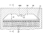
図4に示すように、補強板45には複数の穴57、59、61がエッチング法により穿たれている。図4と図5を対比すると良く分かるように、補強板45の長方形の穴57は、スペーサ35内の圧力室37の列の背面に当たり、また、この長方形穴57の内側に存在する多数の短冊形の島部分58は、それぞれ個々の圧力室37の背面に位置しており、前述したように圧電素子50の各櫛歯部分の先端を各圧力室37の背面のフィルム43へ接合するための仲介となっている。また、図4に示す楕円形又は長円形の穴59は、図5に示すリザーバ39とインク供給路49とが接続する供給路出口49Bに当たり、その楕円形穴59の周囲の破線で囲んだ部分45Aはインク供給路49の出口の周囲部分と接着するための部分である。また、図4に示すウィング状の穴61は、図5に示すリザーバ39の背面に当たっている(供給路出口49Bの部分は除く)。
【0022】
ここで注目すべきことは、補強板45において、リザーバ39の背面に当たるウィング状穴61が、図2に示した従来のウィング状穴21のように中央部分で途切れているのではなく、圧力室37の列に沿ってリザーバ39の一端から他端までの全範囲に亙って連続している点である(この穴61の領域で、フィルム43は変形可能であって圧力室37からのインク噴流の圧力を吸収するように、つまりコンプライアンスとして、作用する)。これに伴い、リザーバ39の幅Wよりも供給路出口49Bの幅(幅W方向の直径)D1は小さく設計され、かつ、供給路出口49Bはリザーバ39に対して、圧力室37とは逆側の縁へ寄せて配置され、圧力室37側の縁からは離れている。このような構成により、インク吐出時にどの圧力室37からインクが噴出しても、リザーバ39背面のフィルム43がそのインク噴流のエネルギーを効果的に吸収することができるので、クロストークが低減される。
【0023】
以下、上記構成の下での本実施形態の作用について説明する。
【0024】
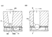
図6(A)は、本実施形態におけるインクに含まれる気泡の流れを示し、図6(B)は図1に示した従来のヘッドのそれを示している。
【0025】
図6(A)に示す本実施形態では、インク供給路出口49Bの面積が、図6(B)に示す従来ヘッドのインク供給路9の出口面積よりも小さい。インク流量を同じとした場合、インク供給路出口での流速は出口面積に半比例するから、本実施形態のインク供給路出口での流速v1は、従来ヘッドの出口流速v2よりも大きい。また、本実施形態ではインク供給路49内の流速は出口49Bに近づくほど増大していく。そのため、本実施形態の方が従来ヘッドよりも気泡を押し流す力が強く、しかも最も気泡がトラップされ易い曲がり角であるインク供給路出口49Bで気泡を押し流す力は最大となるから、気泡が滞留しにくい。
【0026】
また、気泡がインク供給路内で供給路径近くのサイズに成長した場合、図6(B)に示す従来ヘッドではインク供給路9の出口でその大きな気泡73がリザーバ7の壁面に当たって停留するおそれがあるが、図6(A)に示す本実施形態ではインク供給路出口39Bの径が小さいため気泡71も小粒でありリザーバ39内を通り易い。
【0027】
図7(A)は、本実施形態におけるリザーバ39背面のフィルム43のコンプライアンスCとインク供給路49のイナータンスMを示しており、図7(B)は、このコンプライアンスCとイナータンスMをもつインク流路の等価回路を示している(Rは粘性等による流路の抵抗を示し、Iはインク流量を示す)。
【0028】
インク吐出時に圧力室37からリザーバ39へインク噴流が噴出することは、図7(B)の等価回路にステップ状の外乱が加わったようなものであり、これによってMC回路が発振する。回路理論から明らかなように、Cが大きくMが小さいほど発振の圧力振幅は小さい。本実施形態では、図4、5を参照して説明したように、リザーバ39背面でフィルム43がコンプライアンスとして作用する領域が従来ヘッドよりも広く且つ従来ヘッドのように中央部で途切れることがないので、従来ヘッドよりもCが大きい。また、インク供給路49は出口では細いが、入口に近づくほど太くなっているので、インク供給路49全体のMは小さい。従って、リザーバ39内の圧力振幅は小さくクロストークは小さい。
【0029】
図8は、上述した気泡滞留防止及びクロストーク低減の作用を効果的にするための好ましい寸法関係を示している。
【0030】
すなわち、インク供給路49の出口49Bでの幅(直径)D1は、リザーバ39の深さD2より小さいことが望ましい。それにより、インク供給路49からリザーバ39へ入った気泡がリザーバ39内を通り易くなる。但し、必ずしもD1<D2でなければならないわけではなく、D1>D2であってもインク流速が適当に高ければ気泡は停留しない。また、リザーバ39の幅Wは、インク供給路49の出口幅D1よりも大きいことが望ましく、リザーバ39の深さD2よりも大きければ更に望ましい。これにより、リザーバ背面のフィルム43のコンプライアンスが大きくなり、クロストークの低減効果が大きくなる。
【0031】
図9は、本発明の原理が利用できるインク供給路49の形状又は構造についての幾つかの変形例を示す。
【0032】
図9(A)の例では、インク供給路49は、入口49A付近と出口49B付近にテーパが付けられて入口49Aと出口49Bが細く、他の部分は太い同一径となっており、そのような形状の穴を開けた2個の部材81、83を接合して作られている。図9(B)のインク供給路49は、出口49Bにだけテーパが付けられて出口49Bが最も細く、他部分は太い同一径となっており、そのような形状の穴を開けた2個の部材85、87を接合して作られている。図9(C)のインク供給路49は、出口49Bの若干上流側でテーパが付けられて、出口49Bは最も細く同一径となっており、テーパ部より上流側は太い同一径となっており、そのような形状の穴を開けた3個の部材89、91、93を接合して作られている。
【0033】
図10は、インク供給路49の更に別の変形例を示している。
【0034】
図10(B)、(C)はそれぞれ図10(A)のF−F線、G−G線によるインク供給路49の断面図である。このインク供給路49の断面は、出口49Bにおいて楕円形であって、これはリザーバ39背面のフィルムのコンプライアンスCの増大に寄与し、また、他の太い部分では円形であって、これはインク供給路49のインナータンスMの最小化に寄与する。
【0035】
図11は、インク供給路49の更にまた別の変形例を示す。
【0036】
このインク供給路49は、ヘッドのケーシング47内を斜めに貫通しており、出口付近にはテーパが付けられていて出口49Bが最も細くなっている。尚、番号101はインクカートリッジ(図示せず)に差し込まれる針を示し、番号103はインクのゴミを除去するフィルタを示している。通常、インクカートリッジはリザーバ39に比較してかなり大きいので、インクカートリッジの所定箇所からリザーバ39へインクを導くために、インク供給路49が斜めに配されている。
【0037】
図12はインク供給路の別の配置例を説明するための、補強板45の変形例の断面図である。
【0038】
この補強板45では、インクリザーバ39の背面に当たる穴113の一端が、圧力室の列の背面に当たる穴57より外へ延び出ていて、この穴1143の延び出ている端部の脇に、インク供給路の出口に当たる穴111が形成されている。これは、インクリザーバが圧力室の列から外れた場所まで延び出ていて、この延び出た部分にインク供給路の出口が接続していることを意味する。この構成によれば、圧力室前のリザーバの全域で圧力室からのインク噴流を吸収することができるので、クロストークの低減効果は一層良くなる。しかし、インク供給路を圧力室の列の外方へ配置した分だけ、ヘッドのサイズは大きくなる。
【0039】
図13は、上記実施形態にかかるインクジェット印刷ヘッド31を用いたインクジェットプリンタの全体構成を示す。
【0040】
プリンタ120は、上述したような構成のインクジェット印刷ヘッド31と、このインクジェット印刷ヘッドを移動させるキャリッジ機構123と、用紙を搬送する紙送り機構と125、これらインクジェット印刷ヘッド121、キャリッジ機構123及び紙送り機構125を駆動し制御する制御回路121とを備える。この様なプリンタは、コンピュータシステムの出力装置、ファクシミリ端末装置、ワードプロセッサ用プリンタ、ATM用プリンタなど様々な印刷用途に用いることができる。
【0041】
以上、本発明の一実施形態を説明したが、上記実施形態はあくまで本発明の説明のための例示であり、本発明を上記実施形態にのみ限定する趣旨ではない。従って、本発明は、上記実施形態以外の様々な形態でも実施することができるものである。
【図面の簡単な説明】
【図1】従来のインクジェット印刷ヘッドの、図2のB−B線に沿った断面図。
【図2】図1のA−A線に沿った補強板15の断面図。
【図3】本発明の一実施形態にかかるインクジェット印刷ヘッドの、図4、5のE−E線に沿った断面図。
【図4】図3のC−C線に沿った補強板45の断面図。
【図5】図3のD−D線に沿ったスペーサ35の断面図。
【図6】インクに含まれる気泡の流れを本実施形態(A)と従来ヘッド(B)で対比して示した図。
【図7】本実施形態におけるリザーバ39背面のフィルム43のコンプライアンスCとインク供給路49のイナータンスM、及びコンプライアンスCとイナータンスMをもつインク流路の等価回路を示した図。
【図8】本実施形態における好ましい寸法関係を示した図。
【図9】本発明の原理が利用できるインク供給路49の形状又は構造についての幾つかの変形例を示した図。
【図10】インク供給路49の更に別の変形例を示した図。
【図11】インク供給路49の更にまた別の変形例を示した図。
【図12】インク供給路の別の配置例を説明するための、補強板45の変形例の断面図。
【図13】本発明のインクジェット印刷ヘッドを用いたインクジェットプリンタの全体の構成図。
【符号の説明】
31 インクジェット印刷ヘッド
33 ノズル
35 スペーサ
37 圧力室
39 インクリザーバ
43 フィルム
45 補強板
46 流路ユニット
47 ケーシング
49 インク供給路
49A インク供給路の入口
49B インク供給路の出口
50 圧電素子
57、59、61、111、113 補強板の穴[0001]
BACKGROUND OF THE INVENTION
The present invention relates to an ink jet print head, and more particularly to an improvement in an ink flow path for preventing air bubbles from staying and crosstalk during ink ejection.
[0002]
[Prior art]
FIG. 1 shows a typical cross-sectional configuration of a conventional ink jet print head 1 related to the present invention.
[0003]
The
[0004]
The back surfaces of the pressure chambers 5 and the
[0005]
Referring to FIG. 1 again, the tips of the comb-like portions of the
[0006]
[Problems to be solved by the invention]
Ink flowing from the ink cartridge to the
[0007]
When ink is ejected, the ink jet from the pressure chamber 5 is triggered in the
[0008]
Crosstalk is likely to occur when the nozzles near the center of the nozzle row are driven. The reason is as follows. In this case, an ink jet flows from the pressure chamber 5 near the center to the center of the
[0009]
Accordingly, an object of the present invention is to prevent bubbles from staying in the ink flow path.
[0010]
Another object of the present invention is to suppress crosstalk during ink ejection.
[0011]
[Means for Solving the Problems]
An ink jet print head according to a first aspect of the present invention includes a plurality of ink discharge nozzles arranged in a row, a plurality of pressure chambers arranged in a row that respectively communicate with the nozzles, An ink reservoir having a predetermined width and depth that extends along the row and communicates with the pressure chambers in common, and a flexible film that covers at least a part of the outer surface of the ink reservoir in a deformable state; An ink supply path communicating with the ink reservoir. The region covering the ink reservoir in a state where the flexible film can be deformed is continuously in the vicinity of the pressure chamber along at least the range from one end to the other end of the pressure chamber along the row of pressure chambers. And sing.
[0012]
An ink jet print head according to a second aspect of the present invention includes a plurality of ink discharge nozzles arranged in a row, a plurality of pressure chambers arranged in a row that respectively communicate with the nozzles, and the pressure chambers. An ink reservoir having a predetermined width and depth that extends along the row and communicates with the pressure chambers in common, and an ink supply path that communicates with the ink reservoir. The outlet of the ink supply path is arranged at a location near the center of the ink reservoir and on the opposite side of the pressure chamber.
[0013]
An ink jet print head according to a third aspect of the present invention includes a plurality of ink discharge nozzles arranged in a row, a plurality of pressure chambers arranged in a row that respectively communicate with the nozzles, and the pressure chambers. An ink reservoir having a predetermined width and depth that extends along the row and communicates with the pressure chambers in common, an ink supply path that communicates with the ink reservoir, and at least a part of the outer surface of the ink reservoir can be deformed And a flexible film that acts to absorb pressure ejected from the pressure chamber to the ink reservoir. The outlet of the ink supply path is located at the center of the ink reservoir in the direction along the row of pressure chambers, and is located on the opposite side of the pressure chamber side. The width of the outlet is smaller than the width of the ink reservoir. Further, the region covering the ink reservoir in a state where the flexible film can be deformed is continuous in the vicinity of the pressure chambers and at least from one end to the other end of the pressure chamber rows in the vicinity of the pressure chambers. And sing.
[0014]
According to the ink jet print head, the flexible film effectively absorbs the pressure of the ink jet from any pressure chamber, thereby reducing crosstalk.
[0015]
The present invention further includes an ink jet printer having the above-described ink jet print head, a carriage mechanism for moving the ink jet print head, a paper feed mechanism for transporting paper, and a control circuit for driving and controlling them. Also provide.
[0016]
DETAILED DESCRIPTION OF THE INVENTION
FIG. 3 shows a cross-sectional configuration of an
[0017]
The
[0018]
A resin or metal flexible and
[0019]
The
[0020]
4 is a cross-sectional view of the reinforcing
[0021]
As shown in FIG. 4, the reinforcing
[0022]
What should be noted here is that, in the reinforcing
[0023]
Hereinafter, the operation of the present embodiment under the above configuration will be described.
[0024]
6A shows the flow of bubbles contained in the ink in this embodiment, and FIG. 6B shows that of the conventional head shown in FIG.
[0025]
In this embodiment shown in FIG. 6A, the area of the ink
[0026]
Further, when bubbles grow to a size close to the diameter of the supply path in the ink supply path, there is a possibility that the
[0027]
FIG. 7A shows the compliance C of the
[0028]
The ejection of the ink jet from the
[0029]
FIG. 8 shows a preferable dimensional relationship for making the above-described bubble retention prevention and crosstalk reduction effective.
[0030]
That is, the width (diameter) D1 at the
[0031]
FIG. 9 shows several variations on the shape or structure of the
[0032]
In the example of FIG. 9A, the
[0033]
FIG. 10 shows still another modification of the
[0034]
10B and 10C are cross-sectional views of the
[0035]
FIG. 11 shows still another modification of the
[0036]
The
[0037]
FIG. 12 is a cross-sectional view of a modified example of the reinforcing
[0038]
In the reinforcing
[0039]
FIG. 13 shows the overall configuration of an inkjet printer using the
[0040]
The
[0041]
As mentioned above, although one Embodiment of this invention was described, the said embodiment is an illustration for description of this invention to the last, and is not the meaning which limits this invention only to the said embodiment. Therefore, the present invention can be implemented in various forms other than the above-described embodiment.
[Brief description of the drawings]
FIG. 1 is a cross-sectional view of a conventional inkjet print head taken along line BB in FIG.
FIG. 2 is a cross-sectional view of a reinforcing
3 is a cross-sectional view of the inkjet print head according to the embodiment of the present invention, taken along line EE of FIGS.
4 is a cross-sectional view of a reinforcing
5 is a cross-sectional view of the
FIG. 6 is a diagram showing the flow of bubbles contained in ink in comparison between the present embodiment (A) and a conventional head (B).
FIG. 7 is a view showing an equivalent circuit of a compliance C of the
FIG. 8 is a diagram showing a preferable dimensional relationship in the present embodiment.
FIG. 9 is a diagram showing several modified examples of the shape or structure of the
10 is a view showing still another modified example of the
FIG. 11 is a view showing still another modification of the
FIG. 12 is a cross-sectional view of a modified example of the reinforcing
FIG. 13 is an overall configuration diagram of an ink jet printer using the ink jet print head of the present invention.
[Explanation of symbols]
31
Claims (3)
前記ノズルにそれぞれ連通する、列に並べられた複数の圧力室と、
前記圧力室の列に沿って延び、前記複数の圧力室に共通に連通するインクリザーバと、
前記インクリザーバの上面を変形可能な状態で覆う可撓性のフィルムと、
前記インクリザーバの上面に連通するインク供給路と
前記インク供給路に貫通されているケーシングと、
前記ケーシングと前記フィルムとの間に介在し前記インク供給路に貫通される補強板と
を備え、
前記インクリザーバの上面に、前記インク供給路の出口である供給路出口があり、
前記補強板に、前記供給路出口につながり前記インク供給路の一部となる第一の穴と、前記インクリザーバに対向する領域に形成された第二の穴とが空いており、
前記圧力室の列に沿って延びて前記圧力室の列から遠い、前記インクリザーバを形成する内壁面に、その内壁面から前記供給路出口の両脇へと前記圧力室の側に張り出した二つの張出部があり、
前記インクリザーバには、それぞれの前記張出部の間にある、前記供給路出口に繋がる第1の部分と、それぞれの前記張出部の前記第1の部分の反対側の第2の部分とがあり、
前記インクリザーバの第1の部分および第2の部分はつながっており、前記張出部によって互いに区切られることなく、前記第2の部分は前記張出部よりも前記圧力室の列側において連続しており、
前記補強板における前記第一の穴の周囲部分と、前記ケーシングにおける前記インク供給路の周囲部分とが、前記それぞれの張出部を支えとして、前記張出部上で接着されている、
インクジェット印刷ヘッド。A plurality of ink ejection nozzles arranged in a row;
A plurality of pressure chambers arranged in a row, each communicating with the nozzle;
An ink reservoir extending along the row of pressure chambers and in common communication with the plurality of pressure chambers;
A flexible film covering the upper surface of the ink reservoir in a deformable state;
An ink supply path communicating with the upper surface of the ink reservoir; a casing penetrating the ink supply path;
A reinforcing plate interposed between the casing and the film and penetrating through the ink supply path;
On the upper surface of the ink reservoir , there is a supply path outlet that is an outlet of the ink supply path,
The reinforcing plate has a first hole connected to the outlet of the supply path and serving as a part of the ink supply path , and a second hole formed in a region facing the ink reservoir,
Far from the column of the pressure chamber extend along columns of the pressure chamber, overhanging inner wall surface forming the ink reservoir, the side of the pressure chamber and from the inner wall surface to the opposite sides of said supply path outlet two There are two overhangs,
The ink reservoir includes a first portion between the overhang portions, which is connected to the supply path outlet, and a second portion of each overhang portion on the opposite side of the first portion. There is
The first portion and the second portion of the ink reservoir are connected to each other and are not separated from each other by the overhanging portion, and the second portion is continuous on the row side of the pressure chamber with respect to the overhanging portion. And
And the surrounding portion of said first bore in said reinforcing plate, and the surrounding portion of the ink supply path in the casing, the support the respective projecting portions are bonded on said extended portion,
Inkjet print head.
前記供給路出口の、前記圧力室の列に直交する方向に沿った幅が、前記インクリザーバの、前記圧力室の列に直交する方向に沿った最大の幅より小さく、前記供給路出口の形状が、前記インクリザーバの延びた方向に長いほぼ楕円又は長円であり、
前記第二の穴が、前記圧力室の列に沿って前記インクリザーバの一端から他端までの範囲に連続して亙っている、
請求項1記載のインクジェット印刷ヘッド。The supply path outlet is disposed at a central portion of the ink reservoir in a direction along the row of the pressure chambers, and at a position close to the side opposite to the pressure chamber side;
The width of the supply passage outlet along the direction perpendicular to the row of pressure chambers is smaller than the maximum width of the ink reservoir along the direction perpendicular to the row of pressure chambers, and the shape of the supply passage outlet Is substantially oval or oval long in the direction in which the ink reservoir extends,
The second hole continuously extends in a range from one end of the ink reservoir to the other end along the row of pressure chambers;
The ink jet print head according to claim 1.
前記インクジェット印刷ヘッドを移動させるキャリッジ機構と、
用紙を搬送する紙送り機構と、
前記インクジェット印刷ヘッド、前記キャリッジ機構及び前記紙送り機構を駆動し制御する制御回路とを備え、
前記インクジェット印刷ヘッドが、
列に並べられた複数のインク吐出ノズルと、
前記ノズルにそれぞれ連通する、列に並べられた複数の圧力室と、
前記圧力室の列に沿って延び、前記複数の圧力室に共通に連通するインクリザーバと、
前記インクリザーバの上面を変形可能な状態で覆う可撓性のフィルムと、
前記インクリザーバの上面に連通するインク供給路と
前記インク供給路に貫通されているケーシングと、
前記ケーシングと前記フィルムとの間に介在し前記インク供給路に貫通される補強板と
を備え、
前記インクリザーバの上面に、前記インク供給路の出口である供給路出口があり、
前記補強板に、前記供給路出口につながり前記インク供給路の一部となる第一の穴と、前記インクリザーバに対向する領域に形成された第二の穴とが空いており、
前記圧力室の列に沿って延びて前記圧力室の列から遠い、前記インクリザーバを形成する内壁面に、その内壁面から前記供給路出口の両脇へと前記圧力室の側に張り出した二つの張出部があり、
前記インクリザーバには、それぞれの前記張出部の間にある、前記供給路出口に繋がる第1の部分と、それぞれの前記張出部の前記第1の部分の反対側の第2の部分とがあり、
前記インクリザーバの第1の部分および第2の部分はつながっており、前記張出部によって互いに区切られることなく、前記第2の部分は前記張出部よりも前記圧力室の列側において連続しており、
前記補強板における前記第一の穴の周囲部分と、前記ケーシングにおける前記インク供給路の周囲部分とが、前記それぞれの張出部を支えとして、前記張出部上で接着されている、
インクジェットプリンタ。An inkjet printhead;
A carriage mechanism for moving the inkjet print head;
A paper feed mechanism for conveying paper,
A control circuit that drives and controls the ink jet print head, the carriage mechanism, and the paper feed mechanism;
The ink jet print head comprises:
A plurality of ink ejection nozzles arranged in a row;
A plurality of pressure chambers arranged in a row, each communicating with the nozzle;
An ink reservoir extending along the row of pressure chambers and in common communication with the plurality of pressure chambers;
A flexible film covering the upper surface of the ink reservoir in a deformable state;
An ink supply path communicating with the upper surface of the ink reservoir; a casing penetrating the ink supply path;
A reinforcing plate interposed between the casing and the film and penetrating through the ink supply path;
On the upper surface of the ink reservoir , there is a supply path outlet that is an outlet of the ink supply path,
The reinforcing plate has a first hole connected to the outlet of the supply path and serving as a part of the ink supply path , and a second hole formed in a region facing the ink reservoir,
Far from the column of the pressure chamber extend along columns of the pressure chamber, overhanging inner wall surface forming the ink reservoir, the side of the pressure chamber and from the inner wall surface to the opposite sides of said supply path outlet two There are two overhangs,
The ink reservoir includes a first portion between the overhang portions, which is connected to the supply path outlet, and a second portion of each overhang portion on the opposite side of the first portion. There is
The first portion and the second portion of the ink reservoir are connected to each other and are not separated from each other by the overhanging portion, and the second portion is continuous on the row side of the pressure chamber with respect to the overhanging portion. And
And the surrounding portion of said first bore in said reinforcing plate, and the surrounding portion of the ink supply path in the casing, the support the respective projecting portions are bonded on said extended portion,
Inkjet printer.
Priority Applications (1)
| Application Number | Priority Date | Filing Date | Title |
|---|---|---|---|
| JP2002236801A JP4210900B2 (en) | 2002-08-15 | 2002-08-15 | Ink jet print head and ink jet printer |
Applications Claiming Priority (1)
| Application Number | Priority Date | Filing Date | Title |
|---|---|---|---|
| JP2002236801A JP4210900B2 (en) | 2002-08-15 | 2002-08-15 | Ink jet print head and ink jet printer |
Related Parent Applications (1)
| Application Number | Title | Priority Date | Filing Date |
|---|---|---|---|
| JP10203353A Division JP2000033713A (en) | 1998-07-17 | 1998-07-17 | Ink jet print head and ink jet printer |
Publications (3)
| Publication Number | Publication Date |
|---|---|
| JP2003063010A JP2003063010A (en) | 2003-03-05 |
| JP2003063010A5 JP2003063010A5 (en) | 2005-10-27 |
| JP4210900B2 true JP4210900B2 (en) | 2009-01-21 |
Family
ID=19196397
Family Applications (1)
| Application Number | Title | Priority Date | Filing Date |
|---|---|---|---|
| JP2002236801A Expired - Fee Related JP4210900B2 (en) | 2002-08-15 | 2002-08-15 | Ink jet print head and ink jet printer |
Country Status (1)
| Country | Link |
|---|---|
| JP (1) | JP4210900B2 (en) |
Families Citing this family (5)
| Publication number | Priority date | Publication date | Assignee | Title |
|---|---|---|---|---|
| JP5428869B2 (en) | 2010-01-06 | 2014-02-26 | セイコーエプソン株式会社 | Liquid ejecting head and liquid ejecting apparatus |
| US10821729B2 (en) | 2013-02-28 | 2020-11-03 | Hewlett-Packard Development Company, L.P. | Transfer molded fluid flow structure |
| US9902162B2 (en) | 2013-02-28 | 2018-02-27 | Hewlett-Packard Development Company, L.P. | Molded print bar |
| JP6068684B2 (en) | 2013-02-28 | 2017-01-25 | ヒューレット−パッカード デベロップメント カンパニー エル.ピー.Hewlett‐Packard Development Company, L.P. | Forming fluid flow structures |
| US9724920B2 (en) | 2013-03-20 | 2017-08-08 | Hewlett-Packard Development Company, L.P. | Molded die slivers with exposed front and back surfaces |
-
2002
- 2002-08-15 JP JP2002236801A patent/JP4210900B2/en not_active Expired - Fee Related
Also Published As
| Publication number | Publication date |
|---|---|
| JP2003063010A (en) | 2003-03-05 |
Similar Documents
| Publication | Publication Date | Title |
|---|---|---|
| JP2000033713A (en) | Ink jet print head and ink jet printer | |
| KR100738102B1 (en) | Piezoelectric inkjet printhead | |
| JP3386108B2 (en) | Ink jet recording head | |
| KR20160026709A (en) | Liquid discharge head and head unit using the same | |
| EP1024003B1 (en) | Ink jet recording head with improved ink supply channels | |
| JP2020015261A (en) | Liquid ejection head | |
| JP3665370B2 (en) | Inkjet recording device | |
| US6467885B2 (en) | Ink jet record head | |
| JP4210900B2 (en) | Ink jet print head and ink jet printer | |
| JP3552024B2 (en) | Ink jet recording head | |
| JP4453965B2 (en) | Ink jet recording head and recording apparatus | |
| JPS5840508B2 (en) | Impulse type multi-nozzle inkjet head | |
| JP6648459B2 (en) | Liquid ejection head and liquid ejection device | |
| JP2002127406A (en) | Liquid ejector | |
| JP2001287361A (en) | Ink jet recording head | |
| CN111347786B (en) | Liquid ejecting head and liquid ejecting apparatus | |
| US20210114374A1 (en) | Liquid ejecting head | |
| JP3173561B2 (en) | Laminated ink jet recording head and driving method thereof | |
| KR20070079296A (en) | Piezoelectric inkjet printhead | |
| JP3284431B2 (en) | Ink jet recording device | |
| JP2992756B2 (en) | Inkjet head | |
| JP3589236B2 (en) | Ink jet recording head and image recording apparatus using the same | |
| JP3634555B2 (en) | Inkjet recording head | |
| JP3514131B2 (en) | Ink jet recording head | |
| JP3531495B2 (en) | Ink jet recording head |
Legal Events
| Date | Code | Title | Description |
|---|---|---|---|
| A621 | Written request for application examination |
Free format text: JAPANESE INTERMEDIATE CODE: A621 Effective date: 20050527 |
|
| RD02 | Notification of acceptance of power of attorney |
Free format text: JAPANESE INTERMEDIATE CODE: A7422 Effective date: 20050527 |
|
| A521 | Written amendment |
Free format text: JAPANESE INTERMEDIATE CODE: A523 Effective date: 20050719 |
|
| A977 | Report on retrieval |
Free format text: JAPANESE INTERMEDIATE CODE: A971007 Effective date: 20070423 |
|
| A131 | Notification of reasons for refusal |
Free format text: JAPANESE INTERMEDIATE CODE: A131 Effective date: 20070426 |
|
| A521 | Written amendment |
Free format text: JAPANESE INTERMEDIATE CODE: A523 Effective date: 20070622 |
|
| A131 | Notification of reasons for refusal |
Free format text: JAPANESE INTERMEDIATE CODE: A131 Effective date: 20070830 |
|
| A521 | Written amendment |
Free format text: JAPANESE INTERMEDIATE CODE: A523 Effective date: 20071029 |
|
| TRDD | Decision of grant or rejection written | ||
| A01 | Written decision to grant a patent or to grant a registration (utility model) |
Free format text: JAPANESE INTERMEDIATE CODE: A01 Effective date: 20081002 |
|
| A01 | Written decision to grant a patent or to grant a registration (utility model) |
Free format text: JAPANESE INTERMEDIATE CODE: A01 |
|
| A61 | First payment of annual fees (during grant procedure) |
Free format text: JAPANESE INTERMEDIATE CODE: A61 Effective date: 20081015 |
|
| FPAY | Renewal fee payment (event date is renewal date of database) |
Free format text: PAYMENT UNTIL: 20111107 Year of fee payment: 3 |
|
| R150 | Certificate of patent or registration of utility model |
Free format text: JAPANESE INTERMEDIATE CODE: R150 |
|
| FPAY | Renewal fee payment (event date is renewal date of database) |
Free format text: PAYMENT UNTIL: 20111107 Year of fee payment: 3 |
|
| FPAY | Renewal fee payment (event date is renewal date of database) |
Free format text: PAYMENT UNTIL: 20121107 Year of fee payment: 4 |
|
| FPAY | Renewal fee payment (event date is renewal date of database) |
Free format text: PAYMENT UNTIL: 20121107 Year of fee payment: 4 |
|
| FPAY | Renewal fee payment (event date is renewal date of database) |
Free format text: PAYMENT UNTIL: 20131107 Year of fee payment: 5 |
|
| LAPS | Cancellation because of no payment of annual fees |