JP4203183B2 - Control valve for hot water boiler - Google Patents
Control valve for hot water boiler Download PDFInfo
- Publication number
- JP4203183B2 JP4203183B2 JP15631999A JP15631999A JP4203183B2 JP 4203183 B2 JP4203183 B2 JP 4203183B2 JP 15631999 A JP15631999 A JP 15631999A JP 15631999 A JP15631999 A JP 15631999A JP 4203183 B2 JP4203183 B2 JP 4203183B2
- Authority
- JP
- Japan
- Prior art keywords
- valve
- pilot
- gas
- hot water
- burner
- Prior art date
- Legal status (The legal status is an assumption and is not a legal conclusion. Google has not performed a legal analysis and makes no representation as to the accuracy of the status listed.)
- Expired - Fee Related
Links
Images


Classifications
-
- F—MECHANICAL ENGINEERING; LIGHTING; HEATING; WEAPONS; BLASTING
- F23—COMBUSTION APPARATUS; COMBUSTION PROCESSES
- F23N—REGULATING OR CONTROLLING COMBUSTION
- F23N5/00—Systems for controlling combustion
- F23N5/02—Systems for controlling combustion using devices responsive to thermal changes or to thermal expansion of a medium
- F23N5/027—Systems for controlling combustion using devices responsive to thermal changes or to thermal expansion of a medium using mechanical means
-
- F—MECHANICAL ENGINEERING; LIGHTING; HEATING; WEAPONS; BLASTING
- F23—COMBUSTION APPARATUS; COMBUSTION PROCESSES
- F23N—REGULATING OR CONTROLLING COMBUSTION
- F23N1/00—Regulating fuel supply
- F23N1/007—Regulating fuel supply using mechanical means
-
- F—MECHANICAL ENGINEERING; LIGHTING; HEATING; WEAPONS; BLASTING
- F23—COMBUSTION APPARATUS; COMBUSTION PROCESSES
- F23N—REGULATING OR CONTROLLING COMBUSTION
- F23N1/00—Regulating fuel supply
- F23N1/08—Regulating fuel supply conjointly with another medium, e.g. boiler water
- F23N1/087—Regulating fuel supply conjointly with another medium, e.g. boiler water using mechanical means
-
- F—MECHANICAL ENGINEERING; LIGHTING; HEATING; WEAPONS; BLASTING
- F23—COMBUSTION APPARATUS; COMBUSTION PROCESSES
- F23N—REGULATING OR CONTROLLING COMBUSTION
- F23N5/00—Systems for controlling combustion
- F23N5/02—Systems for controlling combustion using devices responsive to thermal changes or to thermal expansion of a medium
- F23N5/10—Systems for controlling combustion using devices responsive to thermal changes or to thermal expansion of a medium using thermocouples
- F23N5/107—Systems for controlling combustion using devices responsive to thermal changes or to thermal expansion of a medium using thermocouples using mechanical means, e.g. safety valves
-
- F—MECHANICAL ENGINEERING; LIGHTING; HEATING; WEAPONS; BLASTING
- F23—COMBUSTION APPARATUS; COMBUSTION PROCESSES
- F23N—REGULATING OR CONTROLLING COMBUSTION
- F23N2227/00—Ignition or checking
- F23N2227/22—Pilot burners
-
- F—MECHANICAL ENGINEERING; LIGHTING; HEATING; WEAPONS; BLASTING
- F23—COMBUSTION APPARATUS; COMBUSTION PROCESSES
- F23N—REGULATING OR CONTROLLING COMBUSTION
- F23N2235/00—Valves, nozzles or pumps
- F23N2235/12—Fuel valves
Description
【0001】
【発明の属する技術分野】
この発明は、缶体内の湯温を設定温度に自動制御する常火パイロット方式の貯湯式ボイラーのコントロールバルブに関する。
【0002】
【従来の技術】
従来のこの種の貯湯式ボイラーのコントロールバルブは、たとえば、図3に例示されているように、メインガス流路にメインバーナ用ガバナ弁MGV′を備え、パイロットガス流路にはパイロットバーナ用ガバナ弁PGV′を備えており、上記メインバーナ用ガバナ弁MGV′は、不使用時には点火ツマミ1′と一体の点火操作軸2′の先端に設けられたテーパカム2a′でそのガスバルブV4′をダイヤフラム15′とともに連動レバー30′を介して調圧バネ16′に抗して持上げ閉止した状態に保持する構造となっており、パイロットバーナ用ガバナ弁PGV′はダイヤフラム15″とガスバルブV4″及び調圧バネ16″からなる構造となっている。
そこで、点火に際し、先ず、点火ツマミ1′を「止」の位置から「パイロット」の位置まで回動した後、一定のストロークだけ押動すると、電磁安全弁装置MV′のマグネット弁V1′を点火操作軸2′で押し開くため、ガス入口5a′からのガスはパイロットガス流路に装備されたパイロットバーナ用ガバナ弁PGV′を経てパイロットバーナPB′に供給され、マッチ、ライター等でパイロット点火を行うことによりパイロット炎c′を形成しマグネット弁V1′を開弁保持する。このとき、メインバーナ用ガバナ弁MGV′のガスバルブV4′は未だ閉止状態にある。その後、点火ツマミ1′の押圧を解いて点火ツマミ1′を「パイロット」の位置から「開」の位置まで回動すると、点火操作軸2′のテーパカム2a′によるメインバーナ用ガバナ弁MGV′のガスバルブV4′の持上げ閉止が解除され、ガスバルブV4′を開弁しフリー状態として以後はダイヤフラム15′と連動してガバナ弁として働くようになっている。
また、マグネット弁V1′が器具栓を兼用しているため、マグネット弁V1′を強制的に閉弁する機構が必要なことから、電磁安全弁装置MV′への電力の供給を遮断するスイッチS′をマグネット回路に備え、このスイッチS′を点火ツマミ1′が「止」位置になったときスイッチS′がOFFしてマグネット弁V1′を閉じる構造となっている。
【0003】
さらに、缶体A′内の湯温が設定温度より低いときは、感熱棒B′によりスナップレバー23′を介してスナップ板25′を反転させスナップ弁V5′を開いてメインバーナにガスを供給し先のパイロット炎c′でこれに着火し缶体A′内の湯温を設定温度にまで上昇する。缶体A′内の湯温が設定温度に達すると、感熱棒B′がこれを感知してスナップ板25′を元位置(スタンバイ位置)に戻すため、スナップ弁V5′は閉じてメインバーナを消火しスタンバイ状態に復帰する構造となっている。図中F′はマグネット回路に組み込まれた温度ヒューズ、28′は温度設定用ネジで、スナップレバー23′の基端部を支承して備えられている。31′はパイロットフィルターである。
【0004】
【発明が解決しようとする課題】
しかしながら、上記従来のコントロールバルブでは、メインバーナ用のガバナ弁MGV′とパイロットバーナ用のガバナ弁PGV′とを各別に装備した2ガバナ方式を採っているため、構造の複雑化は勿論のこと、コントロールバルブ自体の大型化は免れ難く、コスト的にも高くなるという問題点があった。
また、マグネット回路に電気スイッチS′と温度ヒューズF′を組み込んでいるので、マグネット回路抵抗の経時的増加が懸念され、電気抵抗が増加するとマグネット回路に流れる電流が低下するという問題点も併せ有していた。
【0005】
この発明の貯湯式ボイラーのコントロールバルブは上記課題を解決し、パイロット流量からメイン流量までの広い制御域を1つのガバナで制御できるようにして、上記従来の技術の問題点を解消した貯湯式ボイラーのコントロールバルブの提供を目的としている。
【0006】
【課題を解決するための手段】
上記課題を解決するこの発明の請求項1記載の貯湯式ボイラーのコントロールバルブは、
上流のガス流路を開閉するマグネット弁を備えた電磁安全弁装置と、パイロットガス口に備えたパイロット弁と、メインバーナへの流路に備えた器具栓とを備え、
点火ツマミの点火操作軸には上記パイロット弁と上記器具栓をそれぞれ開閉する器具栓用カムとパイロット弁用カムとを一体に備えたカム体を回転方向にのみ固定して備え、
点火ツマミの押し操作により上記マグネット弁が開弁され、点火ツマミの回動操作により上記パイロット弁用カムで上記パイロット弁を開弁してパイロットバーナへガス供給され、パイロット炎で加熱される熱電対の起電力により上記マグネット弁が開弁保持され、点火ツマミの押圧を解いたその後の点火ツマミの回動操作により上記器具栓用カムで器具栓を開弁してメインバーナへガス供給されるものであり、
一方、缶体内の湯温を感知して進退する感熱棒によりスナップ弁を開閉してメインバーナを点滅し缶体内の湯温を設定温度に自動制御する貯湯式ボイラーのコントロールバルブであって、
上記パイロット弁と器具栓とにガスを供給する流路に、ガス圧により調圧バネとバランスするところまでダイヤフラム及びガスバルブが動き、バルブシートに対するガスバルブの接離によりガス流路の開度が調節され、上記メインバーナへのガス流量とパイロットバーナへのガス流量に見合ったガス量が常時正確に保たれてパイロット流量からメイン流量までの広い制御域が得られる1つのガバナ弁を備えたことを要旨とする。
【0008】
上記課題を解決するこの発明の請求項2載の貯湯式ボイラーのコントロールバルブは、上記請求項1記載の貯湯式ボイラーのコントロールバルブにおいて、
上記バルブに対するシート面はゴムモールド及び研磨によりシート性が高められていることを要旨とする。
【0009】
上記課題を解決するこの発明の請求項3記載の貯湯式ボイラーのコントロールバルブは、上記請求項1または2記載の貯湯式ボイラーのコントロールバルブにおいて、
上記バルブはバルブ軸にガイドピンが遊挿されて倒れ防止を図っていることを要旨とする。
【0010】
上記課題を解決するこの発明の請求項4記載の貯湯式ボイラーのコントロールバルブは、上記請求項1ないし3のいずれかに記載の貯湯式ボイラーのコントロールバルブにおいて、 上記パイロットバーナは熱電対の加熱を兼備する常火パイロットバーナであることを要旨とする。
【0011】
上記構成を有するこの発明の請求項1記載の貯湯式ボイラーのコントロールバルブは、点火ツマミの押し回し操作でマグネット弁の開弁とパイロットバーナへの点火が行れ、パイロット炎で加熱される熱電対の起電力によりマグネット弁が開弁保持され、点火ツマミの押圧を解いたその後の回動操作で器具栓を開弁してメインバーナへのガス供給を可能としたスタンバイ状態となり、一方、缶体内の湯温を感知して進退する感熱棒によりスナップ弁が開閉されてメインバーナを点滅することにより缶体内の湯温を設定温度に自動制御する貯湯式ボイラーにおいて、上記メインバーナへのガス流量とパイロットバーナへのガス流量をバルブとバルブシートとの関係位置がパイロット流量とメイン流量に見合ったガス量が常時正確に安定して得られるように保たれてパイロット流量からメイン流量までの広い制御域が得られる1つのガバナ弁で安定制御するようにした。この結果、従来の2ガバナ方式のものに比べ構造の簡略化は勿論のこと、コスト的にも安く提供できる。
【0012】
また、ガバナ弁のバルブとバルブシートの加工精度の確保とバルブの倒れ防止に対する配慮とがなされているから、パイロット流量からメイン流量までの広い制御域を1つのガバナ弁で対処できる。
【0013】
上記構成を有するこの発明の請求項2、3記載の貯湯式ボイラーのコントロールバルブは、バルブに対するシート面はゴムモールド及び研磨によりシート性が高められ、また、バルブはバルブ軸にガイドピンが遊挿されて倒れ防止を図っているから、バルブとバルブシートとの関係位置が常に正確に保たれる。
【0014】
上記構成を有するこの発明の請求項4記載の貯湯式ボイラーのコントロールバルブは、パイロットバーナが熱電対の加熱を兼備する常火パイロットバーナであるため、パイロット炎の消火によりマグネット弁は閉弁される。この結果、マグネット回路に電気スイッチを設けたもののように、回路抵抗の経時的増加による起電力の低下はなく信頼性が高い。
【0015】
【発明の実施の形態】
以上説明したこの発明の構成、作用を一層明かにするために、以下この発明の貯湯式ボイラーのコントロールバルブの好適な実施の形態について図面を参照して説明する。
【0016】
図1及び図2において、1は点火ツマミで、この点火ツマミ1の押し回し操作でマグネット弁V1の開弁とパイロットバーナPBへの点火が行いうるようになっている。すなわち、点火ツマミ1と一体の点火操作軸2に器具栓用カム3aとパイロット弁用カム3bとを一体に備えたカム体3を回転方向にのみ固定して備え、上記点火操作軸2の先端延長軸4を点火操作軸2と同一軸線上のガス流路5の上流側に備えられた電磁安全弁装置MVと関連させている。
上記電磁安全弁MVは、バネ6で閉止方向に付勢して備えられたマグネット弁V1と、このマグネット弁V1と一体の吸着板7を電磁石Mの吸着面8に接離するように対向して備えた構造となっており、上記点火操作軸2と一体の先端延長軸4は上記電磁安全弁MVのマグネット弁V1に同一軸心を保って接離するように位置している。そして、この先端延長軸4を有する点火操作軸2はバネ9で復帰方向(後退方向)に付勢されている。
【0017】
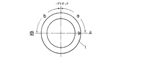
そこで、点火ツマミ1を軸方向に一定のストロークだけ復帰バネ9に抗して押し込むと、点火操作軸2と一体の先端延長軸4でマグネット弁V1を押し開くと同時にマグネット弁V1と一体の吸着板7を電磁石Mの吸着面8に押し当てる。次いで、点火ツマミ1を押したまま「止」位置から「パイロット」位置まで図示反時計方向へ一定の角度(略90度)aだけ回動すると、点火操作軸2に備えたカム体3も回動してパイロット弁用カム3bでパイロット弁V2を閉止用バネ10に抗して押し開き、ガス流路5のガス入口5aからのガスをマグネット弁V1から後述するガバナ弁GVでパイロット流量に見合った安定したガス圧に制御してパイロット弁V2からパイロットガス入口11→パイロットガス流路12を経てパイロットバーナPBに供給する。そこで、パイロットバーナPBにマッチ、ライター等で点火すると、パイロットバーナPBにパイロット炎cが形成される。
【0018】
上記パイロットバーナPBに点火されると、パイロット炎cで熱電対TCを加熱するため、加熱される熱電対TCの起電力でマグネット弁V1は開弁保持される。すなわち、パイロット炎cで熱電対TCが加熱されると、熱電対TCと接続されている上記電磁安全弁装置MVの電磁石Mが熱電対TCの起電力により励磁されて吸着板7を電磁石Mの吸着面8に吸着し、吸着板7と一体のマグネット弁V1を開弁保持する。
上記マグネット弁V1が開弁保持された後、点火ツマミ1の押圧を解くと、点火ツマミ1だけが「パイロット」位置を保ったまま復帰バネ9で点火操作軸2、先端延長軸4とともに元位置まで後退して戻る。しかし、パイロット弁V2はカム体3のパイロット弁用カム3bで開弁されていて、パイロットバーナPBは燃焼を続けているので、引き続き熱電対TCは加熱されてマグネット弁V1を開放状態に維持している。
【0019】
次いで、上記点火ツマミ1の押圧を解いたその後の回動操作で器具栓V3を開弁してメインバーナMBへのガス供給を可能とする。すなわち、点火ツマミ1の押し回し及び押圧解除後、点火ツマミ1を「パイロット」位置から「開」位置まで図示反時計方向へ一定の角度(略90度)bだけ回動すると、点火操作軸2に備えたカム体3も回動して器具栓用カム3aで器具栓V3を閉止用バネ14に抗して押し開き、ガス流路5のガス入口5aからのガスをマグネット弁V1から後述するガバナ弁GVでメイン流量に見合った安定したガス圧に制御して器具栓V3からスナップ弁V5を経てメインバーナMBに供給する。そこで、メインバーナMBには先のパイロット炎cで着火されメイン炎dを形成する。
【0020】
上記ガバナ弁GVは、二次ガス圧によりダイヤフラム15を押し、その力が調圧バネ16とバランスするところまでダイヤフラム15及びガスバルブV4が動き、そのバルブシート17に対するガスバルブV4の接離によりガス流路5の開度を調節し、上流側の供給ガス圧に変動があっても使用中のガス量を下流側において一定に保ってガス圧を安定させるもので、ダイヤフラム15と連動するガスバルブV4に対するシート面17はゴムモールド17a及び研磨によりシート性を高めてガスバルブV4とバルブシート17の加工精度の向上を図り、併せて、ガスバルブV4はそのバルブ軸18に備えたガイド孔19に固定ガイドピン20を同一軸心を保って遊挿しガスバルブV4の倒れ防止を図ることにより、ガスバルブV4とバルブシート17との関係位置が常時正確に保たれるようになしている。
したがって、点火操作にともなうパイロット点火時にはパイロット弁V2の開弁によりパイロットバーナPBへ、たとえば、100キロカロリー/時間のガス量が、また、後述する缶体A内の湯温を感知して開閉するスナップ弁体SVのスナップ弁V5の開弁によるメイン着火時にはメインバーナMBへ、たとえば、2万〜3万キロカロリー/時間のガス量が安定して供給されるようにパイロットガス量からメインガス量までの広い制御域が1つのガバナ弁GVで正確、かつ、安定して制御できるように構成されている。図中21は調圧バネ16のバネ力を調節する調節ネジ、22はキャップである。
【0021】
上記、スナップ弁体SVは、缶体A内の湯温を感知してガス流路5を開閉するためのもので、缶体A内に挿入される感熱棒Bが湯温を感知して伸縮することにより、スナップレバー23を介して押圧体24でスナップ板25を押圧又は押圧解除することでスナップ弁V5を開閉するようになっている。
上記感熱棒Bは湯温を感知して伸縮する線膨張率の大きい、たとえば、銅ケース26に線膨張率の小さい、たとえば、アンバー27を組み込んで湯温の高低変化により銅ケース26が伸縮することでアンバー27が進退移動するようになっており、また、スナップ板25は一方(スナップ弁V5の閉止方向)へは自動復帰する反転バネ板で椀状に形成され、このスナップ板25の外周寄りを押圧体24で押圧するようになっている。28は温度調節ネジで、スナップレバー23の基端部を支承してスナップレバー23の作動支点を兼ねており、この温度調節ネジ28でアンバー27の押動力に対する押圧体24でのスナップ板25の押圧力の強弱を調整することにより、スナップ弁V5の開閉時間をコントロールして湯温調節ができるようになっている。
【0022】
そこで、缶体A内の湯温が設定温度より低くなると、感熱棒Bがこれを感知して銅ケース26が収縮するため、アンバー27が前進(図示左方)しスナップレバー23を図示左方へ温度調節ネジ28を支点として押動するから、スナップ板25はスナップレバー23の先端部で押圧体24を介して図示左方へその復元力に抗して押され反転する(図1の鎖線の状態参照)。したがって、スナップ弁V5はスナップ板25の反転力によりその復帰発条29に抗して図示左方へ移動し開弁されるためにメインバーナMBへのガス流路5は開かれメインバーナMBへガスが供給され、先に点火しているパイロット炎cでこれに着火しメインバーナMBにメイン炎dを形成することで、たとえば、自然対流方式の集熱器(図示せず)を加熱して缶体A内の湯温を昇温せしめる。
メインバーナMBの燃焼により缶体A内の湯温が上昇して設定温度にまで達すると、感熱棒Bがこれを感知して銅ケース26が伸長するため、アンバー27が後退(図示右方)してスナップレバー23によるスナップ板25の押圧が解かれ、スナップ板25は図1の実線の状態に自力復帰しスナップ弁V5は復帰発条29で図示右方へ押動されて閉弁する。したがって、メインバーナMBへのガス流路5は閉ざされメインバーナMBへのガス供給は停止されメインバーナMBのメイン炎dは消火する。
このようにして缶体A内の湯温は常時設定温度に維持されるものである。なお、Fは温度ヒューズで、マグネット回路に備えられ、缶体A内の湯温が異常に温度上昇したときに溶断しマグネット弁V1を閉じガスを遮断するものである。
【0023】
上記構成において、点火ツマミ1を「止」の位置から「パイロット」の位置まで押し回してパイロットバーナPBにパイロット炎cが形成された後、その押圧を解いて点火ツマミ1を「パイロット」位置から「開」の位置まで回動してスタンバイ状態となした後は、缶体A内の湯温の高低を感熱棒Bが感知してメインバーナMBへのガス流路5をスナップ弁体SVで開閉してメインバーナMBの燃焼、消火を自動的に行うことにより缶体A内の湯温を常時設定温度に維持するものであり、また、点火ツマミ1を「開」の位置から「止」の位置まで逆に回動することでパイロット弁V2及び器具栓V3が閉止してパイロット炎cは消火しパイロット炎cによる熱電対TCの加熱も停止されるので、熱電対TCによる起電力はなくなってマグネット弁V1も閉弁するものであるが、ガス流路5に装備されたガバナ弁GVは、ガスバルブV4とその弁シート17との加工精度の確保及びガスバルブV4の倒れ防止に対する配慮がなされていることにより、パイロット流量からメイン流量までの広い制御域を1つのガバナ弁GVで安定制御することができる。そして、缶体A内の湯温制御は感熱棒Bとスナップ弁体SVとを組み合せて自動的にコントロールする。
また、常火パイロットバーナPBを用いてマグネット弁V1が閉弁される構造としたから、マグネット回路抵抗の経時的増加による起電力の低下が懸念されることもない。なお、上記実施の形態のように、換気不良時(酸欠時)等の安全性を高めるにはパイロット炎の消火によりマグネット弁を即座に閉弁させる不燃防止の構造とするのが望ましい。
【0024】
以上この発明の実施の形態の一例について説明したが、この発明はこうした実施の形態に何等限定されるものではなく、この発明の要旨を逸脱しない範囲において種々なる態様で実施し得ることは勿論である。
【0025】
【発明の効果】
この発明は、以上説明したような形態で実施され、以下に記載されるような効果を奏する。
【0026】
この発明の請求項1記載の貯湯式ボイラーのコントロールバルブによれば、点火ツマミの押し回し操作でマグネット弁の開弁とパイロットバーナへの点火が行れ、パイロット炎で加熱される熱電対の起電力によりマグネット弁が開弁保持され、点火ツマミの押圧を解いたその後の回動操作で器具栓を開弁してメインバーナへのガス供給を可能としたスタンバイ状態となり、一方、缶体内の湯温を感知して進退する感熱棒によりスナップ弁が開閉されてメインバーナを点滅することにより缶体内の湯温を設定温度に自動制御する貯湯式ボイラーにおいて、上記メインバーナへのガス流量とパイロットバーナへのガス流量をバルブとバルブシートとの関係位置がパイロット流量とメイン流量に見合ったガス量が常時正確に安定して得られるように保たれてパイロット流量からメイン流量までの広い制御域が得られる1つのガバナ弁で安定制御するようにしたから、従来の2ガバナ方式のものに比べ構造の簡略化は勿論のこと、コスト的にも安く提供できる。
【0027】
また、ガバナ弁のバルブとバルブシートの加工精度の確保とバルブの倒れ防止に対する配慮とがなされているから、パイロット流量からメイン流量までの広い制御域を1つのガバナ弁で対処できる。
【0028】
この発明の請求項2、3記載の貯湯式ボイラーのコントロールバルブによれば、バルブに対するシート面はゴムモールド及び研磨によりシート性が高められ、また、バルブはバルブ軸にガイドピンが遊挿されて倒れ防止を図っているから、バルブとバルブシートとの関係位置が常に正確に保たれる。
【0029】
この発明の請求項4記載の貯湯式ボイラーのコントロールバルブによれば、パイロットバーナが熱電対の加熱を兼備する常火パイロットバーナであるため、パイロット炎の消火によりマグネット弁は閉弁されるから、マグネット回路に電気スイッチを設けたもののように、回路抵抗の経時的増加による起電力の低下はなく安全である。
【図面の簡単な説明】
【図1】この発明の貯湯式ボイラーのコントロールバルブの一例を示した概略展開断面図である。
【図2】点火ツマミの回動操作範囲の一例を示した正面図である。
【図3】従来のこの種のコントロールバルブを示した概略展開断面図である。
【符号の説明】
1…点火ツマミ
MV…電磁安全弁装置
V1…マグネット弁
PB…パイロットバーナ
TC…熱電対
V3…器具栓
A…缶体
B…感熱棒
SV…スナップ弁体
V5…スナップ弁
MB…メインバーナ
GV…ガバナ弁
V4…ガスバルブ
17…バルブシート
17a…ゴムモールド
20…ガイドピン[0001]
BACKGROUND OF THE INVENTION
The present invention relates to a control valve for a hot water storage-type boiler of a normal fire pilot type that automatically controls the hot water temperature in a can body to a set temperature.
[0002]
[Prior art]
For example, as shown in FIG. 3, a conventional control valve for this type of hot water storage boiler includes a main burner governor valve MGV 'in the main gas flow path, and a pilot burner governor in the pilot gas flow path. The governor valve MGV ′ for the main burner is provided with a valve PGV ′. When not in use, the gas valve V 4 ′ is diaphragmed by a taper cam 2 a ′ provided at the tip of an
Therefore, at the time of ignition, first, the ignition knob 1 ′ is rotated from the “stop” position to the “pilot” position and then pushed by a certain stroke, so that the magnet valve V 1 ′ of the electromagnetic safety valve device MV ′ is ignited. The gas from the gas inlet 5a 'is supplied to the pilot burner PB' via the pilot burner governor valve PGV 'equipped in the pilot gas flow path, and is ignited by a match, lighter, etc. By doing so, a pilot flame c 'is formed and the magnet valve V 1 ' is held open. At this time, the gas valve V 4 ′ of the main burner governor valve MGV ′ is still closed. Thereafter, when the ignition knob 1 'is released and the ignition knob 1' is rotated from the "pilot" position to the "open" position, the governor valve MGV 'for the main burner by the taper cam 2a' of the ignition operation shaft 2 'is turned on. The lifting and closing of the gas valve V 4 ′ is released, and the gas valve V 4 ′ is opened to be in a free state. Thereafter, the gas valve V 4 ′ functions as a governor valve in conjunction with the diaphragm 15 ′.
In addition, since the magnet valve V 1 ′ also serves as an instrument plug, a mechanism for forcibly closing the magnet valve V 1 ′ is required. Therefore, a switch that cuts off the power supply to the electromagnetic safety valve device MV ′. 'equipped with the magnet circuit, the switch S' S is OFF to close the magnet valve V 1 'to structure the ignition knob 1' switch S when the becomes "stop" position '.
[0003]
Further, the can body A 'when the hot water temperature in is lower than the set temperature, the heat-sensitive rod B' of gas to the main burner by opening the snap valve V 5 'by inverting the'
[0004]
[Problems to be solved by the invention]
However, since the conventional control valve adopts a two governor system in which the governor valve MGV ′ for the main burner and the governor valve PGV ′ for the pilot burner are separately provided, the structure is naturally complicated. The increase in size of the control valve itself is unavoidable, and the cost is increased.
In addition, since the electrical switch S ′ and the thermal fuse F ′ are incorporated in the magnet circuit, there is a concern that the magnet circuit resistance may increase over time, and the current flowing through the magnet circuit decreases as the electrical resistance increases. Was.
[0005]
The control valve of the hot water boiler according to the present invention solves the above-mentioned problems and allows a wide control range from the pilot flow rate to the main flow rate to be controlled by a single governor, thereby eliminating the above-mentioned problems of the prior art. The purpose is to provide a control valve.
[0006]
[Means for Solving the Problems]
A control valve for a hot water storage boiler according to claim 1 of the present invention for solving the above-mentioned problems is provided.
An electromagnetic safety valve device having a magnet valve for opening and closing the upstream gas flow path, a pilot valve provided for the pilot gas port, and an instrument plug provided for the flow path to the main burner,
The ignition operation shaft of the ignition knob is provided with a cam body integrally provided with an instrument plug cam and a pilot valve cam for opening and closing the pilot valve and the instrument plug, respectively, fixed only in the rotation direction,
The magnet valve is opened by pushing operation of the ignition knob is a gas supply to the pilot burner by opening the pilot valve with the cam above the pilot valve by the rotational operation of the ignition knob, thermoelectric that is heated by the pilot flame the magnet valve is opened held by a pair of electromotive force, opens the plug fitting in the cam the plug fitting is gas supplied to the main burner with the rotational operation of the subsequent ignition knob of solving the pressing of the ignition knob And
On the other hand, it is a control valve of a hot water storage boiler that automatically controls the hot water temperature in the can body to the set temperature by opening and closing the snap valve by the heat sensitive rod that senses the hot water temperature in the can body and advances and retreats,
The diaphragm and the gas valve move to the flow path for supplying gas to the pilot valve and the instrument plug until the pressure adjusting spring balances with the gas pressure, and the opening of the gas flow path is adjusted by the contact and separation of the gas valve with respect to the valve seat. , summarized in that with one of the governor valves wide control range of the amount of gas commensurate with the gas flow to the gas flow rate and the pilot burner to the main burner is correctly kept constant from the pilot flow to the main flow is obtained And
[0008]
A control valve for a hot water storage boiler according to
The gist of the sheet surface for the valve is that the sheet properties are enhanced by rubber molding and polishing.
[0009]
A control valve for a hot water storage boiler according to claim 3 of the present invention for solving the above-described problems is the control valve for a hot water storage boiler according to
The gist of the valve is that a guide pin is loosely inserted into the valve shaft to prevent the valve from falling down.
[0010]
The control valve for a hot water storage boiler according to claim 4 of the present invention for solving the above-mentioned problems is the control valve for a hot water storage boiler according to any of claims 1 to 3, wherein the pilot burner heats a thermocouple. The gist is that it is a constant fire pilot burner.
[0011]
The control valve of the hot water boiler according to claim 1 of the present invention having the above-described configuration is a thermocouple that is heated by a pilot flame by opening the magnet valve and igniting the pilot burner by pushing and rotating the ignition knob. Due to the electromotive force of the magnet, the magnet valve is held open, and after the release of the ignition knob is released, the instrument plug is opened to enter the standby state where gas can be supplied to the main burner. In a hot water storage boiler that automatically controls the hot water temperature in the can to a set temperature by opening and closing the snap valve by a heat sensitive rod that senses the temperature of the hot water and advances and retracts, the main flow burner flashes, and the gas flow rate to the main burner As for the gas flow rate to the pilot burner, the relative position of the valve and the valve seat ensures that the gas flow corresponding to the pilot flow rate and the main flow rate is always accurate and stable. And so as to stabilize the control in one of the governor valves wide control area is kept so that from the pilot flow to the main flow is obtained. As a result, as compared with the conventional two governor system, the structure can be simplified and the cost can be reduced.
[0012]
Further, since care and have been made with respect to the valve and prevent collapse of the machining precision of securing the valve of the valve seat of the governor valve, Ru can deal with a wide control range from the pilot flow to the main flow in a single governor valve.
[0013]
The control valve of the hot water storage boiler according to
[0014]
The control valve of the hot water storage boiler according to claim 4 of the present invention having the above configuration is a normal fire pilot burner in which the pilot burner also serves to heat the thermocouple, so that the magnet valve is closed by extinguishing the pilot flame. . As a result, unlike the case where an electric switch is provided in the magnet circuit, the electromotive force does not decrease due to the increase in circuit resistance over time, and the reliability is high.
[0015]
DETAILED DESCRIPTION OF THE INVENTION
In order to further clarify the configuration and operation of the present invention described above, a preferred embodiment of a control valve for a hot water storage boiler according to the present invention will be described below with reference to the drawings.
[0016]
1 and 2, 1 is an ignition knob, ignition of the opening and the pilot burner PB of the magnet valve V 1 is adapted to be carried out by push and turn manipulation of the ignition knob 1. That is, a cam body 3 integrally provided with an
The electromagnetic safety valve MV opposes the magnet valve V 1 urged in the closing direction by the
[0017]
Therefore, when pushed against the ignition knob 1 only return
[0018]
Once ignited the pilot burner PB, to heat the thermocouple TC at the pilot flame c, the magnet valve V 1 in the electromotive force of the thermocouple TC is heated is opened retained. That is, when the thermocouple TC is heated by the pilot flame c, the electromagnet M of the electromagnetic safety valve device MV connected to the thermocouple TC is excited by the electromotive force of the thermocouple TC, and the adsorption plate 7 is adsorbed by the electromagnet M. The magnet valve V 1 that is attracted to the
After the magnet valve V 1 is being opened retained and solving the pressing of the ignition knob 1, the
[0019]
Then, to enable the gas supply to the main burner MB by opening the plug fitting V 3 in the subsequent rotating operation of solving the pressing of the ignition knob 1. That is, after the ignition knob 1 is pushed and released, when the ignition knob 1 is rotated from the “pilot” position to the “open” position by a certain angle (approximately 90 degrees) b in the counterclockwise direction in the figure, the
[0020]
The governor valves GV, press diaphragm 15 by a secondary gas pressure, the diaphragm 15 and the gas valve V 4 moves to where the force is balanced with the
Therefore, the pilot burner PB by the opening of the pilot valve V 2 at the time of pilot ignition with the ignition operation, for example, the amount of
[0021]
The snap valve body SV is for opening and closing the gas flow path 5 by sensing the temperature of the hot water in the can body A. The heat sensitive rod B inserted into the can body A senses the hot water temperature and expands and contracts. by, so as to open and close the snap valve V 5 by releasing pushing or pressing the
The heat-sensitive bar B has a large linear expansion coefficient that expands and contracts when it senses the hot water temperature, for example, a small linear expansion coefficient, for example, an amber 27 is incorporated into the
[0022]
Therefore, when the hot water temperature in the can body A becomes lower than the set temperature, the thermal bar B senses this and the
When the hot water temperature in the can body A rises to the set temperature due to the combustion of the main burner MB, the thermal bar B senses this and the
In this way, the hot water temperature in the can body A is always maintained at the set temperature. Incidentally, F is a temperature fuse, provided in the magnet circuit is configured to shut off the blown gas closed magnet valve V 1 when the hot water temperature in the can body A is abnormally increase in temperature.
[0023]
In the above configuration, after the ignition knob 1 is pushed from the “stop” position to the “pilot” position to form the pilot flame c in the pilot burner PB, the pressure is released and the ignition knob 1 is moved from the “pilot” position. After turning to the “open” position and entering the standby state, the heat sensitive bar B senses the temperature of the hot water in the can body A, and the gas flow path 5 to the main burner MB is opened by the snap valve body SV. By opening and closing and automatically burning and extinguishing the main burner MB, the hot water temperature in the can body A is constantly maintained at the set temperature. Also, the ignition knob 1 is “stopped” from the “open” position. since the pilot flame c by closing the pilot valve V 2 and the plug fitting V 3 by rotating in the opposite to the position to stop also the heating of the thermocouple TC by extinguished pilot flame c, electromotive force due to the thermocouple TC Magne is gone Although DOO valve V 1 is also intended to closed, the governor valve GV that is provided on the gas passage 5, the consideration for the gas valve V 4 and ensure the machining accuracy of the valve seat 17 and the gas valve V 4 of falling prevention As a result, a wide control range from the pilot flow rate to the main flow rate can be stably controlled by one governor valve GV. And the hot water temperature control in the can body A is automatically controlled by combining the heat sensitive rod B and the snap valve body SV.
Nor because the magnet valve V 1 is has a structure that is closed, the decrease in the electromotive force with time increase in the magnet circuit resistance is concerned with the normal fire pilot burner PB. It should be noted that, as in the above-described embodiment, in order to increase safety in the case of poor ventilation (when oxygen is lacking), it is desirable to have a non-combustion prevention structure in which the magnet valve is immediately closed by extinguishing the pilot flame.
[0024]
Although an example of the embodiment of the present invention has been described above, the present invention is not limited to such an embodiment, and can of course be implemented in various modes without departing from the gist of the present invention. is there.
[0025]
【The invention's effect】
The present invention is implemented in the form as described above, and has the effects described below.
[0026]
According to the control valve of the hot water storage boiler according to claim 1 of the present invention, the magnet valve is opened and the pilot burner is ignited by pushing and rotating the ignition knob, and the thermocouple heated by the pilot flame is started. The magnet valve is held open by the electric power, and the instrument plug is opened by the subsequent rotation operation after releasing the pressure of the ignition knob to enter the standby state in which the gas can be supplied to the main burner. In a hot water storage boiler that automatically controls the hot water temperature in the can to a set temperature by flashing the main burner by opening and closing the snap valve by a thermal rod that senses the temperature and moves back and forth, the gas flow rate to the main burner and the pilot burner The gas flow rate to the valve is so that the relative position of the valve and the valve seat can always be obtained accurately and stably in accordance with the pilot flow rate and the main flow rate. As a result, stable control is achieved with a single governor valve that can provide a wide control range from the pilot flow rate to the main flow rate. We can offer cheaply.
[0027]
In addition, since the processing accuracy of the governor valve and the valve seat is ensured and consideration is given to preventing the valve from collapsing, a wide control range from the pilot flow rate to the main flow rate can be dealt with by a single governor valve.
[0028]
According to the control valve of the hot water storage boiler according to
[0029]
According to the control valve of the hot water storage boiler according to claim 4 of the present invention, since the pilot burner is a normal fire pilot burner that combines heating of the thermocouple, the magnet valve is closed by extinguishing the pilot flame. Unlike the case where an electric switch is provided in the magnet circuit, the electromotive force is not lowered due to the increase in circuit resistance over time, and it is safe.
[Brief description of the drawings]
FIG. 1 is a schematic developed sectional view showing an example of a control valve of a hot water storage boiler according to the present invention.
FIG. 2 is a front view showing an example of a rotation operation range of an ignition knob.
FIG. 3 is a schematic developed sectional view showing a conventional control valve of this type.
[Explanation of symbols]
1 ... ignition knob MV ... electromagnetic safety valve V 1 ... magnet valve PB ... pilot burner TC ... thermocouple V 3 ... plug fitting A ... can body B ... thermosensitive rod SV ... snap valve body V 5 ... Snap valve MB ... main burner GV ... governor valve V 4 ... gas valve 17 ...
Claims (4)
点火ツマミの点火操作軸には上記パイロット弁と上記器具栓をそれぞれ開閉する器具栓用カムとパイロット弁用カムとを一体に備えたカム体を回転方向にのみ固定して備え、
点火ツマミの押し操作により上記マグネット弁が開弁され、点火ツマミの回動操作により上記パイロット弁用カムで上記パイロット弁を開弁してパイロットバーナへガス供給され、パイロット炎で加熱される熱電対の起電力により上記マグネット弁が開弁保持され、点火ツマミの押圧を解いたその後の点火ツマミの回動操作により上記器具栓用カムで器具栓を開弁してメインバーナへガス供給されるものであり、
一方、缶体内の湯温を感知して進退する感熱棒によりスナップ弁を開閉してメインバーナを点滅し缶体内の湯温を設定温度に自動制御する貯湯式ボイラーのコントロールバルブであって、
上記パイロット弁と器具栓とにガスを供給する流路に、ガス圧により調圧バネとバランスするところまでダイヤフラム及びガスバルブが動き、バルブシートに対するガスバルブの接離によりガス流路の開度が調節され、上記メインバーナへのガス流量とパイロットバーナへのガス流量に見合ったガス量が常時正確に保たれてパイロット流量からメイン流量までの広い制御域が得られる1つのガバナ弁を備えたことを特徴とする貯湯式ボイラーのコントロールバルブ。 An electromagnetic safety valve device having a magnet valve for opening and closing the upstream gas flow path, a pilot valve provided for the pilot gas port, and an instrument plug provided for the flow path to the main burner,
The ignition operation shaft of the ignition knob is provided with a cam body integrally provided with an instrument plug cam and a pilot valve cam for opening and closing the pilot valve and the instrument plug, respectively, fixed only in the rotation direction,
The magnet valve is opened by pushing operation of the ignition knob is a gas supply to the pilot burner by opening the pilot valve with the cam above the pilot valve by the rotational operation of the ignition knob, thermoelectric that is heated by the pilot flame the magnet valve is opened held by a pair of electromotive force, opens the plug fitting in the cam the plug fitting is gas supplied to the main burner with the rotational operation of the subsequent ignition knob of solving the pressing of the ignition knob And
On the other hand, it is a control valve of a hot water storage boiler that automatically controls the hot water temperature in the can body to the set temperature by opening and closing the snap valve by the heat sensitive rod that senses the hot water temperature in the can body and advances and retreats,
The diaphragm and the gas valve move to the flow path for supplying gas to the pilot valve and the instrument plug until the pressure adjusting spring balances with the gas pressure, and the opening of the gas flow path is adjusted by the contact and separation of the gas valve with respect to the valve seat. , characterized in that it comprises a single governor valve wide control range of the amount of gas commensurate with the gas flow to the gas flow rate and the pilot burner to the main burner is correctly kept constant from the pilot flow to the main flow is obtained Control valve for hot water storage boiler.
Priority Applications (6)
| Application Number | Priority Date | Filing Date | Title |
|---|---|---|---|
| JP15631999A JP4203183B2 (en) | 1999-06-03 | 1999-06-03 | Control valve for hot water boiler |
| ES00111589T ES2247979T3 (en) | 1999-06-03 | 2000-05-30 | CONTROL VALVE FOR A GAS WATER HEATER. |
| DE60022124T DE60022124T2 (en) | 1999-06-03 | 2000-05-30 | Control valve for a gas boiler |
| EP00111589A EP1058058B1 (en) | 1999-06-03 | 2000-05-30 | Control valve for vessel gas water heater |
| US09/584,460 US6345768B1 (en) | 1999-06-03 | 2000-05-31 | Control valve for vessel gas water heater |
| HK01103875A HK1033167A1 (en) | 1999-06-03 | 2001-06-05 | Control valve for vessel gas water heater |
Applications Claiming Priority (1)
| Application Number | Priority Date | Filing Date | Title |
|---|---|---|---|
| JP15631999A JP4203183B2 (en) | 1999-06-03 | 1999-06-03 | Control valve for hot water boiler |
Publications (2)
| Publication Number | Publication Date |
|---|---|
| JP2000346459A JP2000346459A (en) | 2000-12-15 |
| JP4203183B2 true JP4203183B2 (en) | 2008-12-24 |
Family
ID=15625209
Family Applications (1)
| Application Number | Title | Priority Date | Filing Date |
|---|---|---|---|
| JP15631999A Expired - Fee Related JP4203183B2 (en) | 1999-06-03 | 1999-06-03 | Control valve for hot water boiler |
Country Status (6)
| Country | Link |
|---|---|
| US (1) | US6345768B1 (en) |
| EP (1) | EP1058058B1 (en) |
| JP (1) | JP4203183B2 (en) |
| DE (1) | DE60022124T2 (en) |
| ES (1) | ES2247979T3 (en) |
| HK (1) | HK1033167A1 (en) |
Families Citing this family (14)
| Publication number | Priority date | Publication date | Assignee | Title |
|---|---|---|---|---|
| US7569193B2 (en) * | 2003-12-19 | 2009-08-04 | Applied Materials, Inc. | Apparatus and method for controlled combustion of gaseous pollutants |
| US7736599B2 (en) * | 2004-11-12 | 2010-06-15 | Applied Materials, Inc. | Reactor design to reduce particle deposition during process abatement |
| US7682574B2 (en) * | 2004-11-18 | 2010-03-23 | Applied Materials, Inc. | Safety, monitoring and control features for thermal abatement reactor |
| US8095240B2 (en) * | 2004-11-18 | 2012-01-10 | Applied Materials, Inc. | Methods for starting and operating a thermal abatement system |
| US7363923B2 (en) * | 2005-01-05 | 2008-04-29 | Illinois Tool Works Inc. | cooking range assembly and monolithic drip pan |
| US7811082B2 (en) * | 2005-01-05 | 2010-10-12 | Premark Feg, Llc | Gas circuit and pilot light system for cooking range |
| US20100154776A1 (en) * | 2005-01-05 | 2010-06-24 | Charles Czajka | Cooking range burner head assembly |
| US20060147865A1 (en) * | 2005-01-05 | 2006-07-06 | Charles Czajka | Cooking range burner head assembly |
| EP1954926A2 (en) * | 2005-10-31 | 2008-08-13 | Applied Materials, Inc. | Process abatement reactor |
| JP6010276B2 (en) * | 2010-10-29 | 2016-10-19 | 株式会社ガスター | Combustion device |
| US9182051B2 (en) | 2013-07-23 | 2015-11-10 | Moshe Shemer | Gas saver valve and method using the same |
| TWI576542B (en) * | 2016-04-15 | 2017-04-01 | Safety valves for combustion installations | |
| DE102016115113A1 (en) * | 2016-08-15 | 2018-02-15 | Tutech Innovation Gmbh | Gas engine or dual-fuel engine with gas valve and use of a pressure-relieved gas valve therefor |
| CN110388739B (en) * | 2019-07-05 | 2021-05-14 | 广东万家乐燃气具有限公司 | Ignition feedback needle, combustor and gas hot water equipment |
Family Cites Families (7)
| Publication number | Priority date | Publication date | Assignee | Title |
|---|---|---|---|---|
| US3402887A (en) * | 1966-06-16 | 1968-09-24 | Emerson Electric Co | Burner control device for a water heater |
| US3471087A (en) * | 1966-07-20 | 1969-10-07 | Robertshaw Controls Co | Burner control with separate pressure regulator for main and pilot burners |
| US3915378A (en) * | 1973-01-08 | 1975-10-28 | Emerson Electric Co | Manifold valve for domestic gas ovens |
| JPS5875617A (en) * | 1981-10-28 | 1983-05-07 | Matsushita Electric Ind Co Ltd | Gas pressure adjusting apparatus |
| JPS6262125A (en) * | 1985-09-12 | 1987-03-18 | Matsushita Electric Ind Co Ltd | Gas instantaneous hot-water heater |
| US5097818A (en) * | 1989-07-20 | 1992-03-24 | Samsung Electronics, Co., Ltd. | Structure of gas governor |
| US5967776A (en) * | 1998-08-17 | 1999-10-19 | Kim; Han-Joon | Auxiliary tool for occluding apparatus and method of mounting dentiform model on occluding apparatus |
-
1999
- 1999-06-03 JP JP15631999A patent/JP4203183B2/en not_active Expired - Fee Related
-
2000
- 2000-05-30 EP EP00111589A patent/EP1058058B1/en not_active Expired - Lifetime
- 2000-05-30 ES ES00111589T patent/ES2247979T3/en not_active Expired - Lifetime
- 2000-05-30 DE DE60022124T patent/DE60022124T2/en not_active Expired - Fee Related
- 2000-05-31 US US09/584,460 patent/US6345768B1/en not_active Expired - Fee Related
-
2001
- 2001-06-05 HK HK01103875A patent/HK1033167A1/en not_active IP Right Cessation
Also Published As
| Publication number | Publication date |
|---|---|
| EP1058058B1 (en) | 2005-08-24 |
| DE60022124D1 (en) | 2005-09-29 |
| HK1033167A1 (en) | 2001-08-17 |
| DE60022124T2 (en) | 2006-06-22 |
| US6345768B1 (en) | 2002-02-12 |
| JP2000346459A (en) | 2000-12-15 |
| EP1058058A2 (en) | 2000-12-06 |
| ES2247979T3 (en) | 2006-03-16 |
| EP1058058A3 (en) | 2002-07-17 |
Similar Documents
| Publication | Publication Date | Title |
|---|---|---|
| JP4203183B2 (en) | Control valve for hot water boiler | |
| US6571829B2 (en) | Gas control valve in water heater | |
| JPH0134051Y2 (en) | ||
| JPH02502564A (en) | Fuel control valve, its parts and its manufacturing method | |
| US3862820A (en) | Direct burner ignition system | |
| US4002419A (en) | Direct burner ignition system | |
| JPH08303774A (en) | Fire force adjusting mechanism at ignition of gas apparatus | |
| JP4159554B2 (en) | Gas cock device | |
| JPH0652127B2 (en) | Water heater | |
| US1824239A (en) | To milwaukee gas | |
| JPH0144912Y2 (en) | ||
| JPS605246Y2 (en) | Heat adjustment device for gas appliances | |
| JPH0345004Y2 (en) | ||
| JP3128469B2 (en) | Thermal power adjustment mechanism for ignition of gas equipment | |
| JPH0330705Y2 (en) | ||
| JPH0259381B2 (en) | ||
| JPS6042260Y2 (en) | Safety device for flame detector | |
| JP3862846B2 (en) | Main stop type gas water heater | |
| JPH0330704Y2 (en) | ||
| JPH033801Y2 (en) | ||
| JPS6215616Y2 (en) | ||
| JPH0120525Y2 (en) | ||
| JPS591928B2 (en) | Stop-start gas water heater | |
| JPH0133954Y2 (en) | ||
| JPH1054479A (en) | Gas water heater |
Legal Events
| Date | Code | Title | Description |
|---|---|---|---|
| A621 | Written request for application examination |
Free format text: JAPANESE INTERMEDIATE CODE: A621 Effective date: 20060531 |
|
| A977 | Report on retrieval |
Free format text: JAPANESE INTERMEDIATE CODE: A971007 Effective date: 20080418 |
|
| A131 | Notification of reasons for refusal |
Free format text: JAPANESE INTERMEDIATE CODE: A131 Effective date: 20080507 |
|
| A521 | Request for written amendment filed |
Free format text: JAPANESE INTERMEDIATE CODE: A523 Effective date: 20080702 |
|
| TRDD | Decision of grant or rejection written | ||
| A01 | Written decision to grant a patent or to grant a registration (utility model) |
Free format text: JAPANESE INTERMEDIATE CODE: A01 Effective date: 20081007 |
|
| A01 | Written decision to grant a patent or to grant a registration (utility model) |
Free format text: JAPANESE INTERMEDIATE CODE: A01 |
|
| A61 | First payment of annual fees (during grant procedure) |
Free format text: JAPANESE INTERMEDIATE CODE: A61 Effective date: 20081010 |
|
| R150 | Certificate of patent or registration of utility model |
Free format text: JAPANESE INTERMEDIATE CODE: R150 |
|
| FPAY | Renewal fee payment (event date is renewal date of database) |
Free format text: PAYMENT UNTIL: 20111017 Year of fee payment: 3 |
|
| FPAY | Renewal fee payment (event date is renewal date of database) |
Free format text: PAYMENT UNTIL: 20111017 Year of fee payment: 3 |
|
| FPAY | Renewal fee payment (event date is renewal date of database) |
Free format text: PAYMENT UNTIL: 20111017 Year of fee payment: 3 |
|
| S533 | Written request for registration of change of name |
Free format text: JAPANESE INTERMEDIATE CODE: R313533 |
|
| FPAY | Renewal fee payment (event date is renewal date of database) |
Free format text: PAYMENT UNTIL: 20111017 Year of fee payment: 3 |
|
| R350 | Written notification of registration of transfer |
Free format text: JAPANESE INTERMEDIATE CODE: R350 |
|
| FPAY | Renewal fee payment (event date is renewal date of database) |
Free format text: PAYMENT UNTIL: 20141017 Year of fee payment: 6 |
|
| R250 | Receipt of annual fees |
Free format text: JAPANESE INTERMEDIATE CODE: R250 |
|
| LAPS | Cancellation because of no payment of annual fees |