JP4201642B2 - Heat transfer tube and heat exchanger assembled with this heat transfer tube - Google Patents
Heat transfer tube and heat exchanger assembled with this heat transfer tube Download PDFInfo
- Publication number
- JP4201642B2 JP4201642B2 JP2003139339A JP2003139339A JP4201642B2 JP 4201642 B2 JP4201642 B2 JP 4201642B2 JP 2003139339 A JP2003139339 A JP 2003139339A JP 2003139339 A JP2003139339 A JP 2003139339A JP 4201642 B2 JP4201642 B2 JP 4201642B2
- Authority
- JP
- Japan
- Prior art keywords
- heat transfer
- transfer tube
- fluid
- metal wire
- fixed
- Prior art date
- Legal status (The legal status is an assumption and is not a legal conclusion. Google has not performed a legal analysis and makes no representation as to the accuracy of the status listed.)
- Expired - Fee Related
Links
Images


Classifications
-
- Y—GENERAL TAGGING OF NEW TECHNOLOGICAL DEVELOPMENTS; GENERAL TAGGING OF CROSS-SECTIONAL TECHNOLOGIES SPANNING OVER SEVERAL SECTIONS OF THE IPC; TECHNICAL SUBJECTS COVERED BY FORMER USPC CROSS-REFERENCE ART COLLECTIONS [XRACs] AND DIGESTS
- Y02—TECHNOLOGIES OR APPLICATIONS FOR MITIGATION OR ADAPTATION AGAINST CLIMATE CHANGE
- Y02T—CLIMATE CHANGE MITIGATION TECHNOLOGIES RELATED TO TRANSPORTATION
- Y02T10/00—Road transport of goods or passengers
- Y02T10/10—Internal combustion engine [ICE] based vehicles
- Y02T10/12—Improving ICE efficiencies
Description
【0001】
【産業上の利用分野】
本発明は、EGRガス冷却装置等の多管式熱交換器にて、冷却水、冷却風、カーエアコン用冷媒、その他の冷却媒体と、EGRガス、煤を含有する燃焼排気ガス等との熱交換を行うために用いる、伝熱管並びにこの伝熱管を組み付けた熱交換器に係るものである。
【0002】
【従来の技術】
【特許文献1】
特開平11−108578号公報
【特許文献2】
特開2001−227413号公報
【0003】
従来、自動車のエンジン等では、排気ガスの一部を排気ガス系から取り出して、再びエンジンの吸気系に戻し、混合気や吸入空気に加えるEGRシステムが、ガソリンエンジン、ディーゼルエンジンともに用いられていた。EGRシステム、特にディーゼルエンジンの高EGR率のクールドEGRシステムでは、排気ガス中のNOxを低減し、燃費の悪化を防止するとともに、過剰な温度上昇によるEGRバルブの機能低下や耐久性の低下を防止するため、高温のEGRガスを冷却水、冷却風、冷媒、その他の冷却媒体で冷却する装置を設けている。
【0004】
そして、このEGRガス冷却装置は、図5に示す如く、EGRガスが内部を流通可能な複数の細径の伝熱管(1)を配置し、この伝熱管(1)の外側に冷却水や冷却風、冷媒等の冷却媒体を流通させる事により、伝熱管(1)を介してEGRガスと冷却媒体との熱交換を行うものである。
【0005】
このような伝熱管としては、特許文献1記載の発明、特許文献2記載の発明等が知られている。これらの従来公知の伝熱管は、流体の流通する内周面が平滑なものであるから、図6に示す如く、流通する排出ガスに含まれる煤(2)が堆積しやすいものとなる。この伝熱管(1)の内面に、煤(2)が付着して堆積すると、煤(2)が断熱作用を生じ交換熱量が低下し、伝熱管(1)としての性能を低下させるものとなり好ましくない。そこで、従来はこの煤(2)を伝熱管(1)の内面から除去する方法として、伝熱管(1)を一定期間使用した後は、ブラシ状のもので掻き落としたり、伝熱管(1)の冷却作動を停止して伝熱管(1)を高温にする事で煤(2)を焼却して除去する方法が採用されている。
【0006】
【発明が解決しようとする課題】
しかしながら、伝熱管(1)の内面に付着した煤(2)を、ブラシ状のもので掻き落としたり、伝熱管(1)の冷却作動を停止して伝熱管(1)を高温にする事で煤(2)を焼却したりする方法は、多くの手数を要するばかりでなく伝熱管(1)の冷却作動を停止させねば成らず、伝熱管(1)の作業効率を著しく低下させるものとなっている。また、このような欠点を防止し伝熱管(1)の内面への煤(2)の付着を防止する目的で、フッ素樹脂等の表面エネルギーの低いコーティングを伝熱管(1)の内面に施す事も行われている。しかしながら、この表面エネルギーの低いコーティングを伝熱管の内面に施す方法は、フッ素樹脂等の表面エネルギーの低いコーティングが、金属に比較して熱伝導率が小さく伝熱性に乏しいため、本来熱交換器である伝熱管(1)の熱伝達効率を低下させるものとなる。
【0007】
本発明は上述の如き課題を解決しようとするものであって、伝熱管(1)の本来の目的である熱伝達効率を低下させる事が無く、また、伝熱管の冷却作動を停止させずに伝熱管(1)の内面に付着した煤(2)を自動的に除去する事を可能にする。また、この煤(2)の除去を伝熱管(1)の内面への煤(2)の付着量が少ない内に行う事により、煤(2)による伝熱管の熱伝達効率の低下を最小限にしようとするものである。
【0008】
【課題を解決するための手段】
本発明は上述の如き課題を解決するため、第1の発明は、軸方向の一端に流体導入口を、軸方向の他端に流体導出口を設けた素管の内周面に、素管の軸方向と平行に複数本の直線状の金属線を間隔を設けて環状に配置し、この直線状の金属線の少なくとも一端部を素管の流体導入口側に固定すると共にこの直線状の金属線を、流体導入口への流体の導入に伴って揺動し得る強度とし、素管の内周面に付着する煤を直線状の金属線の揺動により剥離可能としたことを特徴とする伝熱管に係るものである。
【0009】
また、第2の発明は、軸方向の一端に流体導入口を、軸方向の他端に流体導出口を設けた素管の内周面に、素管の軸方向と平行に複数本の直線状の金属線を間隔を設けて環状に配置し、この直線状の金属線の少なくとも一端部を素管の流体導入口側に固定すると共にこの直線状の金属線を、流体導入口への流体の導入に伴って揺動し得る強度とし、素管の内周面に付着する煤を直線状の金属線の揺動により剥離可能とした伝熱管を組み付けたことを特徴とする伝熱管を組み付けた熱交換器に係るものである。
【0010】
また、直線状の金属線は、素管の流体導入口から流体導出口迄の全長に渡って連続的に配置し、一端部を流体導入口に、他端部を流体導出口に固定したものであっても良い。
【0011】
また、素管は、流体導入口側から流体導出口側の内面に間隔を設けて固定環を固定し、この複数の固定環の流体導入口側に各々直線状の金属線の一端部を固定して形成したものであっても良い。
【0012】
【作用】
上述の如く構成したものに於いて、素管の流体導入口からEGRガス、煤を含有する燃焼排気ガス等の流体を導入すると、流体は流体導出口方向に流動する過程で煤を流体の内面に付着させると共に、流体の流動エネルギーにより直線状の金属線を振動させ、軸方向に対して上下左右にランダムな振幅で揺動させる。この揺動は、伝熱管内を流れる流体の速度変化や、EGRシステムに振動が発生する場合等に特に発生し易いものとなる。この揺動により、直線状の金属線は素管の内周面に接触して擦る事となり、内周面に付着する煤を、付着の初期に於いて素管の内周面から剥離させることが可能となる。そして、素管の内周面から剥離した煤は流体と共に下流に流出する。
【0013】
そして、直線状の金属線は、流体によって揺動が生じることのない強度に形成すると技術的効果を生じないものであって、流体導入口への流体の導入に伴ってランダムな振幅で揺動し得る強度としている。この強度は、直線状の金属線を短くすれば揺動は生じにくくなるし、長くすれば揺動は生じやすいものとなる。また、直線状の金属線は直径を大きくすれば強度が高まり揺動を生じ難いものとなるし、直径を小さなものとすれば揺動を生じやすいものとなる。
【0014】
また、直線状の金属線は、素管の流体導入口から流体導出口迄の全長に渡って連続的に配置しても良く、この場合は金属管の一端部を流体導入口に、他端部を流体導出口に固定して形成する。
【0015】
また、直線状の金属線は上記の如く一本の金属管を素管の流体導入口から流体導出口迄の全長に渡って連続的に配置しても良いが、素管の軸方向に於いて複数の直線状の金属線を配置しても良い。この場合は、流体導入口側から流体導出口側の内面に間隔を設けて固定環を固定し、この複数の固定環の流体導入口側に各々直線状の金属線の一端部を固定して形成するものである。
【0016】
【実施例】
以下、本発明の伝熱管の一実施例を図面に於て説明すれば、(1)は伝熱管で、流体が内部を流動可能な素管(3)の軸方向の一端に流体導入口(4)を設け、軸方向の他端に流体導出口(5)を形成している。この素管(3)の内周面(6)に、素管(3)の軸方向と平行に複数の直線状の金属線(7)を所望の間隔を設けて環状に配置している。そして、この直線状の金属線(7)の少なくとも一端部(8)を素管(3)の流体導入口(4)の開口縁(10)に係合固定している。また、この直線状の金属線(7)は一実施例に於いて、図1、図2に示す如く、素管(3)の流体導入口(4)から流体導出口(5)迄の全長に渡って配置し、一端部(8)を流体導入口(4)の開口縁(10)に折り曲げて係合固定すると共に、他端部(11)を流体導出口(5)の他端開口縁(12)に折り曲げて係合固定している。
【0017】
また、上記の直線状の金属線(7)はSUS、インコネル等の耐食性金属により形成し、直径を50μ〜250μの範囲で形成する。直線状の金属線(7)の直径を50μよりも細くすると、強度的に弱くなり使用中の断線等を生じ好ましくない。また、直線状の金属線(7)の直径を250μよりも太くすると、直線状の金属線(7)の強度が大きくなり、流体の素管(3)への導入によっても揺動を生じることが少ないか、生じないものとなり、素管(3)の内面に付着した煤(2)の剥離を有効に行うことが出来ないものとなる。このように、直線状の金属線(7)は、流体導入口(4)への流体の導入に伴ってランダムな振幅で揺動し得る強度とし、素管(3)の内周面(6)に付着する煤(2)を直線状の金属線(7)の揺動により剥離可能とするものである。
【0018】
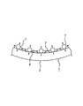
また、上記実施例では、素管(3)の流体導入口(4)から流体導出口(5)迄の全長に渡って一本の直線状の金属線(7)を配置し、一端部(8)を流体導入口(4)の開口縁(10)に折り曲げて係合固定すると共に、他端部(11)を流体導出口(5)の他端開口縁(12)に折り曲げて係合固定している。しかし、他の異なる第2実施例では、図4に示す如く、素管(3)の軸方向に於いて複数本の直線状の金属線(7)を配置しても良い。この場合は、流体導入口(4)側から流体導出口(5)側の内面に、軸方向に於いて所望の間隔毎に固定環(13)を固定する。また、この固定環(13)は、素管(3)の内周面(6)との間に直線状の金属線(7)の挿入間隔(14)を設け、この挿入間隔(14)に直線状の金属線(7)の一端部(8)を挿入して固定環(13)に折り曲げ係合している。この複数の固定環(13)への直線状の金属線(7)の係合固定は、一端部(8)の係合固定位置が流体導入口(4)側に配置されるように固定して形成するものである。
【0019】
上述の如き伝熱管(1)を使用したEGRガス冷却装置(15)である熱交換器を図5に示す。この熱交換器であるEGRガス冷却装置(15)は、円筒状の胴管(16)の両端付近に、内部を密閉可能にチューブシート(17)を一対、接続している。そして、この一対のチューブシート(17)間に、本実施例の伝熱管(1)を複数本、チューブシート(17)を貫通して接続配置している。また、胴管(16)の両端には、EGRガスの導入口(18)と導出口(20)とを設けたボンネット(21)を接続している。
【0020】
更に、胴管(16)の外周には、エンジン冷却水、冷却風、カーエアコン用冷媒等の冷却媒体の流入口(22)と流出口(23)を設ける事により、一対のチューブシート(17)で仕切られた気密空間内を、冷却媒体が流通可能な冷却部(24)としている。また、好ましくはこの冷却部(24)内に、複数の支持板(25)を接合配置し、この支持板(25)に設けた挿通孔(26)に、伝熱管(1)を挿通する事により、バッフルプレートとして伝熱管(1)を安定的に支持するとともに、冷却部(24)内を流動する冷却媒体の流れを蛇行化している。
【0021】
そして、上述の如きEGRガス冷却装置(15)に於いて、導入口(18)から胴管(16)内に高温のEGRガスを導入すると、このEGRガスは胴管(16)内に複数配置した伝熱管(1)内に流入する。この伝熱管(1)を配置した冷却部(24)では、予め伝熱管(1)の外部にエンジン冷却水等の冷却媒体を流通しているので、伝熱管(1)の内外両表面を介してEGRガスと冷却媒体とで熱交換が行われる。
【0022】
上記の熱交換に於いて、伝熱管(1)の内部を流れる流体がディーゼルエンジンの排気ガス等の如く、流体中に煤(2)等を含むものの場合は、伝熱管(1)の内周面にこの煤(2)を付着堆積するものとなる。しかし、本発明の実施例に於いては、素管(3)の流体導入口(4)からEGRガス、煤(2)を含有する燃焼排気ガス等の流体を導入すると、流体は流体導出口(5)方向に流動する過程で、煤(2)を伝熱管(1)の内面に付着させると共に、流体の流動エネルギーにより、図3に示す如く、直線状の金属線(7)を振動させ、軸方向に対して上下左右にランダムな振幅で揺動させる。この揺動により、直線状の金属線(7)は素管(3)の内周面に付着する煤(2)を、付着の初期に於いて素管(3)の内周面(6)から剥離させることが可能となる。そして、素管(3)の内周面(6)から剥離した煤(2)は流体と共に下流に流出する。
【0023】
従って、従来の如く、伝熱管(1)を一定期間使用した後、ブラシ状のもので掻き落としたり、伝熱管(1)の冷却作動を停止して伝熱管(1)を高温にする事で煤(2)を焼却して除去する等の除去手段を取る必要がない。本発明に於いては、伝熱管(1)の内面への煤(2)の付着は自動的に除去されるため、手数を要しないと共に煤(2)の除去に伝熱管(1)の使用を中断することもないものとなる。
【0024】
【発明の効果】
本発明は上述の如く構成したものであるから、伝熱管の本来の目的である熱伝達効率を低下させる事が無く、また、伝熱管の冷却作動を停止させずに伝熱管の内面に付着した煤を自動的に除去する事ができる。また、この煤の除去を伝熱管の内面への付着量が少ない内に行う事ができ、煤による伝熱管の熱伝達効率の低下を最小限にする事ができるものである。
【図面の簡単な説明】
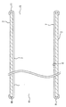
【図1】 本発明の第1実施例を示す斜視図。
【図2】 直線状の金属線と素管との関係を示す一部省略拡大端面図。
【図3】 直線状の金属線による煤の除去状況を示す拡大断面図。
【図4】 第2実施例の拡大断面図。
【図5】 伝熱管を組み付けたEGRガス冷却装置の一例を示す断面図。
【図6】 従来例による伝熱管への煤の付着例を示す拡大断面図。
【符号の説明】
1 伝熱管
2 煤
3 素管
4 流体導入口
5 流体導出口
6 内周面
7 直線状の金属線
8 一端部
11 他端部
13 固定環
15 ガス冷却装置[0001]
[Industrial application fields]
The present invention is a multi-tube heat exchanger such as an EGR gas cooling device, and heat of cooling water, cooling air, refrigerant for car air conditioner, other cooling medium, combustion exhaust gas containing EGR gas, soot, etc. The present invention relates to a heat exchanger tube used for exchanging and a heat exchanger in which the heat exchanger tube is assembled.
[0002]
[Prior art]
[Patent Document 1]
JP 11-108578 A [Patent Document 2]
Japanese Patent Laid-Open No. 2001-227413
Conventionally, in an automobile engine or the like, an EGR system in which a part of exhaust gas is extracted from the exhaust gas system, returned to the engine intake system, and added to the mixture or intake air has been used for both gasoline engines and diesel engines. . EGR systems, especially cooled EGR systems with a high EGR rate for diesel engines, reduce NOx in exhaust gas, prevent fuel consumption deterioration and prevent deterioration of EGR valve function and durability due to excessive temperature rise. Therefore, a device for cooling high-temperature EGR gas with cooling water, cooling air, refrigerant, or other cooling medium is provided.
[0004]
As shown in FIG. 5, this EGR gas cooling device is provided with a plurality of small-diameter heat transfer tubes (1) through which EGR gas can flow, and outside the heat transfer tubes (1), cooling water and cooling By circulating a cooling medium such as wind or refrigerant, heat exchange between the EGR gas and the cooling medium is performed via the heat transfer tube (1).
[0005]
As such a heat transfer tube, an invention described in
[0006]
[Problems to be solved by the invention]
However, by scraping off the scissors (2) adhering to the inner surface of the heat transfer tube (1) with a brush, or stopping the cooling operation of the heat transfer tube (1) and raising the heat transfer tube (1) to a high temperature The method of incinerating the firewood (2) not only requires a lot of work, but also requires the cooling operation of the heat transfer tube (1) to be stopped, which significantly reduces the work efficiency of the heat transfer tube (1). ing. In addition, in order to prevent such defects and to prevent the fouling (2) from adhering to the inner surface of the heat transfer tube (1), a coating having a low surface energy such as fluororesin is applied to the inner surface of the heat transfer tube (1). Has also been done. However, the method of applying this low surface energy coating to the inner surface of the heat transfer tube is essentially a heat exchanger because the coating with low surface energy such as fluororesin has a low thermal conductivity and poor heat transfer compared to metal. The heat transfer efficiency of a certain heat transfer tube (1) is reduced.
[0007]
The present invention is intended to solve the above-described problems, without reducing the heat transfer efficiency, which is the original purpose of the heat transfer tube (1), and without stopping the cooling operation of the heat transfer tube. It is possible to automatically remove the soot (2) adhering to the inner surface of the heat transfer tube (1). In addition, the removal of the soot (2) is performed while the amount of soot (2) attached to the inner surface of the heat transfer tube (1) is small, so that the heat transfer efficiency of the heat transfer tube due to the soot (2) is minimized. It is something to try.
[0008]
[Means for Solving the Problems]
In order to solve the above-described problems, the present invention provides a first pipe on the inner peripheral surface of a pipe having a fluid inlet at one end in the axial direction and a fluid outlet at the other end in the axial direction. A plurality of straight metal wires are arranged in an annular shape in parallel with the axial direction of the tube, and at least one end portion of the straight metal wires is fixed to the fluid inlet side of the raw pipe, and The strength of the metal wire is that it can swing with the introduction of fluid into the fluid inlet, and the wrinkles adhering to the inner peripheral surface of the base tube can be peeled off by swinging the straight metal wire. This relates to a heat transfer tube.
[0009]
Further, the second aspect of the invention provides a plurality of straight lines parallel to the axial direction of the raw pipe on the inner peripheral surface of the raw pipe provided with a fluid inlet at one end in the axial direction and a fluid outlet at the other end in the axial direction. The metal wire is arranged in an annular shape with a space, and at least one end of the straight metal wire is fixed to the fluid inlet side of the base tube, and the straight metal wire is fluidized to the fluid inlet. Assembling a heat transfer tube, which has a strength that can be swung with the introduction of the heat transfer tube, and that can be peeled off by swinging a straight metal wire. Related to the heat exchanger.
[0010]
In addition, the straight metal wire is arranged continuously over the entire length from the fluid inlet to the fluid outlet of the elementary pipe, with one end fixed to the fluid inlet and the other end fixed to the fluid outlet. It may be.
[0011]
In addition, the base tube is fixed to the inner ring from the fluid inlet side to the fluid outlet port side with a fixed ring, and one end of each straight metal wire is fixed to the fluid inlet side of the plurality of fixed rings. It may be formed.
[0012]
[Action]
In the above configuration, when a fluid such as EGR gas or combustion exhaust gas containing soot is introduced from the fluid inlet of the raw pipe, the soot is removed from the inner surface of the fluid in the process of flowing in the direction of the fluid outlet. At the same time, a linear metal wire is vibrated by the fluid flow energy, and is swung with random amplitude vertically and horizontally with respect to the axial direction. This oscillation is particularly likely to occur when the velocity of the fluid flowing in the heat transfer tube changes, or when vibration occurs in the EGR system. By this swinging, the straight metal wire comes into contact with the inner peripheral surface of the raw tube and rubs, and the wrinkles adhering to the inner peripheral surface are peeled off from the inner peripheral surface of the raw tube in the initial stage of attachment. Is possible. And the soot peeled from the inner peripheral surface of the blank pipe flows downstream together with the fluid.
[0013]
The linear metal wire does not produce a technical effect when formed to have a strength that does not cause oscillation by the fluid, and it swings with random amplitude as the fluid is introduced into the fluid inlet. Strength. As for this strength, if the straight metal wire is shortened, the swing is less likely to occur, and if it is longer, the swing is likely to occur. Further, if the diameter of the straight metal wire is increased, the strength is increased and it is difficult to cause the oscillation, and if the diameter is reduced, the oscillation is likely to occur.
[0014]
Further, the straight metal wire may be continuously arranged over the entire length from the fluid inlet to the fluid outlet of the elementary pipe. In this case, one end of the metal pipe is used as the fluid inlet and the other end. The part is fixed to the fluid outlet.
[0015]
In addition, as described above, a straight metal wire may be formed by continuously arranging a single metal tube over the entire length from the fluid inlet to the fluid outlet of the elementary tube, but in the axial direction of the elementary tube. A plurality of straight metal wires may be arranged. In this case, the stationary ring is fixed with an interval from the fluid introduction port side to the inner surface of the fluid outlet port side, and one end of each linear metal wire is fixed to the fluid introduction port side of the plurality of stationary rings. To form.
[0016]
【Example】
Hereinafter, an embodiment of the heat transfer tube of the present invention will be described with reference to the drawings. (1) is a heat transfer tube, and a fluid inlet ( 4) and a fluid outlet (5) is formed at the other end in the axial direction. A plurality of linear metal wires (7) are annularly arranged on the inner peripheral surface (6) of the raw tube (3) in parallel with the axial direction of the raw tube (3) with a desired interval. At least one end (8) of the linear metal wire (7) is engaged and fixed to the opening edge (10) of the fluid introduction port (4) of the elementary pipe (3). In addition, in one embodiment, the straight metal wire (7) is the total length from the fluid inlet (4) to the fluid outlet (5) of the elementary pipe (3) as shown in FIGS. And the other end (11) is opened to the other end of the fluid outlet (5) while the other end (11) is bent and engaged with the opening edge (10) of the fluid inlet (4). It is bent and fixed to the edge (12).
[0017]
The linear metal wire (7) is made of a corrosion-resistant metal such as SUS or Inconel and has a diameter in the range of 50 to 250 μm. If the diameter of the straight metal wire (7) is made thinner than 50μ, the strength becomes weak and undesirably causes disconnection during use. Further, when the diameter of the straight metal wire (7) is thicker than 250 [mu], straight metal wire strength becomes large (7), causing the rocking by introduction into the fluid of the base pipe (3) Is less or does not occur, and the heel (2) attached to the inner surface of the base tube (3) cannot be effectively peeled off. As described above, the straight metal wire (7) has a strength capable of swinging with a random amplitude as the fluid is introduced into the fluid introduction port (4), and the inner peripheral surface (6) of the base tube (3). ) (2) adhering to) can be peeled off by swinging a linear metal wire (7).
[0018]
Moreover, in the said Example, one linear metal wire (7) is arrange | positioned over the full length from the fluid inlet port (4) of the elementary pipe (3) to the fluid outlet port (5), and one end part ( 8) is bent and engaged with the opening edge (10) of the fluid introduction port (4), and the other end portion (11) is bent and engaged with the other end opening edge (12) of the fluid outlet port (5). It is fixed. However, in another different second embodiment, a plurality of linear metal wires (7) may be arranged in the axial direction of the raw tube (3) as shown in FIG. In this case, the fixed ring (13) is fixed to the inner surface from the fluid inlet (4) side to the fluid outlet port (5) side at desired intervals in the axial direction. Further, the fixed ring (13) is provided with an insertion interval (14) of a linear metal wire (7) between the inner pipe (3) and the inner peripheral surface (6), and the insertion interval (14) is provided. One end (8) of the straight metal wire (7) is inserted and engaged with the fixed ring (13) by bending. The engagement and fixation of the linear metal wire (7) to the plurality of fixing rings (13) is fixed so that the engagement fixing position of the one end (8) is arranged on the fluid introduction port (4) side. To form.
[0019]
FIG. 5 shows a heat exchanger which is an EGR gas cooling device (15) using the heat transfer tube (1) as described above. In the EGR gas cooling device (15), which is a heat exchanger, a pair of tube sheets (17) are connected near both ends of a cylindrical body tube (16) so that the inside can be sealed. Between the pair of tube sheets (17), a plurality of the heat transfer tubes (1) of the present embodiment are connected through the tube sheet (17). A bonnet (21) provided with an EGR gas inlet (18) and outlet (20) is connected to both ends of the trunk pipe (16).
[0020]
Further, an outer inlet (22) and an outlet (23) for a cooling medium such as engine cooling water, cooling air, or a car air conditioner refrigerant are provided on the outer periphery of the trunk pipe (16), so that a pair of tube sheets (17 ) Is a cooling section (24) through which a cooling medium can flow. Preferably, a plurality of support plates (25) are joined and disposed in the cooling section (24), and the heat transfer tube (1) is inserted into the insertion hole (26) provided in the support plate (25). Thus, the heat transfer tube (1) is stably supported as a baffle plate, and the flow of the cooling medium flowing in the cooling section (24) is meandered.
[0021]
In the EGR gas cooling device (15) as described above, when high-temperature EGR gas is introduced into the trunk pipe (16) from the introduction port (18), a plurality of EGR gases are arranged in the trunk pipe (16). Into the heat transfer tube (1). In the cooling section (24) in which the heat transfer tube (1) is disposed, a cooling medium such as engine cooling water is circulated in advance to the outside of the heat transfer tube (1), so that both the inner and outer surfaces of the heat transfer tube (1) are passed through. Thus, heat exchange is performed between the EGR gas and the cooling medium.
[0022]
In the heat exchange described above, if the fluid flowing inside the heat transfer tube (1) contains soot (2) in the fluid, such as exhaust gas from a diesel engine, the inner circumference of the heat transfer tube (1) This soot (2) is deposited and deposited on the surface. However, in the embodiment of the present invention, when fluid such as combustion exhaust gas containing EGR gas and soot (2) is introduced from the fluid inlet (4) of the elementary pipe (3), the fluid is fluid outlet. (5) In the process of flowing in the direction, the spear (2) is attached to the inner surface of the heat transfer tube (1) and the fluid energy of the fluid vibrates the straight metal wire (7) as shown in FIG. Oscillate with random amplitude vertically and horizontally with respect to the axial direction. By this swinging, the straight metal wire (7) is attached to the inner peripheral surface (6) of the raw pipe (3) at the initial stage of attachment. Can be peeled off. And the spear (2) peeled from the inner peripheral surface (6) of the raw pipe (3) flows downstream together with the fluid.
[0023]
Therefore, after using the heat transfer tube (1) for a certain period of time as before, scraping it off with a brush or stopping the cooling operation of the heat transfer tube (1) to bring the heat transfer tube (1) to a high temperature. There is no need to take removal measures such as incineration and removal of firewood (2). In the present invention, the adhesion of the soot (2) to the inner surface of the heat transfer tube (1) is automatically removed, so that there is no need for trouble and the use of the heat transfer tube (1) for removing the soot (2). Will not be interrupted.
[0024]
【The invention's effect】
Since the present invention is configured as described above, the heat transfer efficiency, which is the original purpose of the heat transfer tube, is not lowered, and the heat transfer tube does not stop the cooling operation and is attached to the inner surface of the heat transfer tube. Can remove the candy automatically. Further, the removal of the soot can be performed while the amount of adhesion to the inner surface of the heat transfer tube is small, and the decrease in the heat transfer efficiency of the heat transfer tube due to the soot can be minimized.
[Brief description of the drawings]
FIG. 1 is a perspective view showing a first embodiment of the present invention.
FIG. 2 is a partially omitted enlarged end view showing a relationship between a straight metal wire and a raw tube.
FIG. 3 is an enlarged cross-sectional view showing a state of removal of soot by a straight metal wire.
FIG. 4 is an enlarged sectional view of a second embodiment.
FIG. 5 is a cross-sectional view showing an example of an EGR gas cooling device in which a heat transfer tube is assembled.
FIG. 6 is an enlarged cross-sectional view showing an example of soot adhesion to a heat transfer tube according to a conventional example.
[Explanation of symbols]
DESCRIPTION OF
Claims (6)
Priority Applications (1)
| Application Number | Priority Date | Filing Date | Title |
|---|---|---|---|
| JP2003139339A JP4201642B2 (en) | 2003-05-16 | 2003-05-16 | Heat transfer tube and heat exchanger assembled with this heat transfer tube |
Applications Claiming Priority (1)
| Application Number | Priority Date | Filing Date | Title |
|---|---|---|---|
| JP2003139339A JP4201642B2 (en) | 2003-05-16 | 2003-05-16 | Heat transfer tube and heat exchanger assembled with this heat transfer tube |
Publications (2)
| Publication Number | Publication Date |
|---|---|
| JP2004340516A JP2004340516A (en) | 2004-12-02 |
| JP4201642B2 true JP4201642B2 (en) | 2008-12-24 |
Family
ID=33528463
Family Applications (1)
| Application Number | Title | Priority Date | Filing Date |
|---|---|---|---|
| JP2003139339A Expired - Fee Related JP4201642B2 (en) | 2003-05-16 | 2003-05-16 | Heat transfer tube and heat exchanger assembled with this heat transfer tube |
Country Status (1)
| Country | Link |
|---|---|
| JP (1) | JP4201642B2 (en) |
-
2003
- 2003-05-16 JP JP2003139339A patent/JP4201642B2/en not_active Expired - Fee Related
Also Published As
| Publication number | Publication date |
|---|---|
| JP2004340516A (en) | 2004-12-02 |
Similar Documents
| Publication | Publication Date | Title |
|---|---|---|
| JP4707388B2 (en) | Heat transfer tube for combustion exhaust gas containing soot and heat exchanger assembled with this heat transfer tube | |
| US8584447B2 (en) | Filter device for filtering automobile exhaust gas | |
| JP2001159377A (en) | Exhaust gas recirculation cooler | |
| JP2001330394A (en) | Exhaust gas heat exchanger | |
| JP4201642B2 (en) | Heat transfer tube and heat exchanger assembled with this heat transfer tube | |
| JP2007155321A (en) | Small high-temperature heat exchanger such as recovery heat exchanger | |
| JP5227755B2 (en) | EGR cooler | |
| JPH1113555A (en) | Egr gas cooling device | |
| JP2004239600A (en) | Heat transfer pipe externally provided with resin fin member | |
| JP3780729B2 (en) | Recirculation exhaust gas cooling system | |
| JP4266741B2 (en) | Heat transfer tube with fins | |
| JP2000088477A (en) | Apparatus for cooling egr gas | |
| JP2004191034A (en) | Heat transfer pipe internally provided with fin member made of resin material | |
| JP2002350071A (en) | Double pipe heat exchanger | |
| JPH1113550A (en) | Egr cooler | |
| JP2000310161A (en) | Egr cooler | |
| JPH09310991A (en) | Egr gas cooler | |
| JP2004191035A (en) | Heat transfer pipe internally provided with resin pipe | |
| JP2005030677A (en) | Heat transfer tube armored with resin fin member | |
| JP3260400B2 (en) | Exhaust gas purification catalyst | |
| JP2005163621A (en) | Catalytic converter | |
| JP4208632B2 (en) | Heat transfer tube with fins | |
| JP2000161871A (en) | Double piping type heat exchanger | |
| JP2000257512A (en) | Egr cooler | |
| JP2004317060A (en) | Heat transfer pipe with fin member internally mounted |
Legal Events
| Date | Code | Title | Description |
|---|---|---|---|
| A621 | Written request for application examination |
Free format text: JAPANESE INTERMEDIATE CODE: A621 Effective date: 20060501 |
|
| RD02 | Notification of acceptance of power of attorney |
Free format text: JAPANESE INTERMEDIATE CODE: A7422 Effective date: 20060919 |
|
| A131 | Notification of reasons for refusal |
Free format text: JAPANESE INTERMEDIATE CODE: A131 Effective date: 20080421 |
|
| A521 | Written amendment |
Free format text: JAPANESE INTERMEDIATE CODE: A523 Effective date: 20080605 |
|
| TRDD | Decision of grant or rejection written | ||
| A01 | Written decision to grant a patent or to grant a registration (utility model) |
Free format text: JAPANESE INTERMEDIATE CODE: A01 Effective date: 20081001 |
|
| A01 | Written decision to grant a patent or to grant a registration (utility model) |
Free format text: JAPANESE INTERMEDIATE CODE: A01 |
|
| A61 | First payment of annual fees (during grant procedure) |
Free format text: JAPANESE INTERMEDIATE CODE: A61 Effective date: 20081007 |
|
| R150 | Certificate of patent or registration of utility model |
Free format text: JAPANESE INTERMEDIATE CODE: R150 |
|
| FPAY | Renewal fee payment (event date is renewal date of database) |
Free format text: PAYMENT UNTIL: 20111017 Year of fee payment: 3 |
|
| FPAY | Renewal fee payment (event date is renewal date of database) |
Free format text: PAYMENT UNTIL: 20121017 Year of fee payment: 4 |
|
| LAPS | Cancellation because of no payment of annual fees |