JP4200468B1 - Flat door opening and closing mechanism - Google Patents
Flat door opening and closing mechanism Download PDFInfo
- Publication number
- JP4200468B1 JP4200468B1 JP2008101916A JP2008101916A JP4200468B1 JP 4200468 B1 JP4200468 B1 JP 4200468B1 JP 2008101916 A JP2008101916 A JP 2008101916A JP 2008101916 A JP2008101916 A JP 2008101916A JP 4200468 B1 JP4200468 B1 JP 4200468B1
- Authority
- JP
- Japan
- Prior art keywords
- door
- index
- track
- guide
- finger
- Prior art date
- Legal status (The legal status is an assumption and is not a legal conclusion. Google has not performed a legal analysis and makes no representation as to the accuracy of the status listed.)
- Expired - Fee Related
Links
Images


Classifications
-
- E—FIXED CONSTRUCTIONS
- E05—LOCKS; KEYS; WINDOW OR DOOR FITTINGS; SAFES
- E05D—HINGES OR SUSPENSION DEVICES FOR DOORS, WINDOWS OR WINGS
- E05D15/00—Suspension arrangements for wings
- E05D15/06—Suspension arrangements for wings for wings sliding horizontally more or less in their own plane
- E05D15/10—Suspension arrangements for wings for wings sliding horizontally more or less in their own plane movable out of one plane into a second parallel plane
- E05D15/1042—Suspension arrangements for wings for wings sliding horizontally more or less in their own plane movable out of one plane into a second parallel plane with transversely moving carriage
-
- E—FIXED CONSTRUCTIONS
- E05—LOCKS; KEYS; WINDOW OR DOOR FITTINGS; SAFES
- E05F—DEVICES FOR MOVING WINGS INTO OPEN OR CLOSED POSITION; CHECKS FOR WINGS; WING FITTINGS NOT OTHERWISE PROVIDED FOR, CONCERNED WITH THE FUNCTIONING OF THE WING
- E05F1/00—Closers or openers for wings, not otherwise provided for in this subclass
- E05F1/08—Closers or openers for wings, not otherwise provided for in this subclass spring-actuated, e.g. for horizontally sliding wings
- E05F1/16—Closers or openers for wings, not otherwise provided for in this subclass spring-actuated, e.g. for horizontally sliding wings for sliding wings
-
- E—FIXED CONSTRUCTIONS
- E05—LOCKS; KEYS; WINDOW OR DOOR FITTINGS; SAFES
- E05F—DEVICES FOR MOVING WINGS INTO OPEN OR CLOSED POSITION; CHECKS FOR WINGS; WING FITTINGS NOT OTHERWISE PROVIDED FOR, CONCERNED WITH THE FUNCTIONING OF THE WING
- E05F5/00—Braking devices, e.g. checks; Stops; Buffers
- E05F5/003—Braking devices, e.g. checks; Stops; Buffers for sliding wings
-
- E—FIXED CONSTRUCTIONS
- E05—LOCKS; KEYS; WINDOW OR DOOR FITTINGS; SAFES
- E05Y—INDEXING SCHEME RELATING TO HINGES OR OTHER SUSPENSION DEVICES FOR DOORS, WINDOWS OR WINGS AND DEVICES FOR MOVING WINGS INTO OPEN OR CLOSED POSITION, CHECKS FOR WINGS AND WING FITTINGS NOT OTHERWISE PROVIDED FOR, CONCERNED WITH THE FUNCTIONING OF THE WING
- E05Y2201/00—Constructional elements; Accessories therefore
- E05Y2201/20—Brakes; Disengaging means, e.g. clutches; Holders, e.g. locks; Stops; Accessories therefore
- E05Y2201/262—Brakes; Disengaging means, e.g. clutches; Holders, e.g. locks; Stops; Accessories therefore characterised by type of motion
- E05Y2201/266—Brakes; Disengaging means, e.g. clutches; Holders, e.g. locks; Stops; Accessories therefore characterised by type of motion rotary
-
- E—FIXED CONSTRUCTIONS
- E05—LOCKS; KEYS; WINDOW OR DOOR FITTINGS; SAFES
- E05Y—INDEXING SCHEME RELATING TO HINGES OR OTHER SUSPENSION DEVICES FOR DOORS, WINDOWS OR WINGS AND DEVICES FOR MOVING WINGS INTO OPEN OR CLOSED POSITION, CHECKS FOR WINGS AND WING FITTINGS NOT OTHERWISE PROVIDED FOR, CONCERNED WITH THE FUNCTIONING OF THE WING
- E05Y2800/00—Details, accessories and auxiliary operations not otherwise provided for
- E05Y2800/20—Combinations of elements
- E05Y2800/23—Combinations of elements of elements of different categories
- E05Y2800/24—Combinations of elements of elements of different categories of springs and brakes
Abstract
【課題】
極めて簡単な構成によって、一方向の手動の操作力を加えるだけで、隣り合う扉または機枠の端面に当接させることなく扉をスムーズに開閉させることのできるフラットドア、または/および、閉扉行程の終期において、重力や特段の手動の操作力などを加えることなく扉を面一になる位置に引き込むことのできるところの、低廉で簡易なフラットドアを提供する。
【解決手段】
ガイド軌道を、直線軌道とそれに連なる内方の軌道と外方の軌道と直線短軌道とで形成し、または/および、開扉行程の初期において、内方の軌道にガイドされて移動するガイドローラーにより弾性体を作動させ反発力を蓄積させ、開扉行程の終期において、その反発力を解放させるように構成した。
【選択図】図3【Task】
A flat door that can be opened and closed smoothly without touching the adjacent door or the end face of the machine frame by applying a manual operation force in one direction with a very simple configuration, and / or the closing process At the end of this period, a low-priced and simple flat door is provided that allows the door to be pulled into a flush position without applying gravity or special manual operating force.
[Solution]
A guide roller which is formed by a straight track, an inner track continuous therewith, an outer track and a straight short track, or / and which is guided by the inner track in the initial stage of the door opening process. By operating the elastic body, the repulsive force is accumulated, and at the end of the door opening process, the repulsive force is released.
[Selection] Figure 3
Description
本発明は、左方または右方にスライドして、開扉時には開扉される一方の扉が他方の扉または機枠の前面に重なり、閉扉時には前記一方の扉が他方の扉または機枠の前面と面一になるフラットドアの開閉機構に関する。 The present invention slides to the left or right, and when the door is opened, one door that is opened overlaps with the other door or the front of the machine frame, and when the door is closed, the one door is connected to the other door or the machine frame. The present invention relates to a flat door opening / closing mechanism that is flush with the front surface.
フラットドアは、閉扉時には一方の扉の端面が他方の扉または機枠の端面とに接し、ぴたっと閉め切られるようになっている。したがって、それを開扉するにはまず、開扉される一方の扉の端面を他方の扉または機枠の端面からスムーズに引き離さなければならない。そのための工夫を講じた従来の技術としては、例えば特開2002−89125号公報所載の発明がある。この発明にあっては、開扉される扉の側端部に扉と直角になる方向に、手動の操作力を加えて扉を回転させ扉の他の側端部を接触している端面から引き離してから、引き続いて扉に平行する方向に手動の操作力を加えて、その扉を他方の扉に重ねさせていた。すなわち、扉を開くには、二つの異なる方向の力を加える必要があった。 When the flat door is closed, the end surface of one door is in contact with the other door or the end surface of the machine frame, so that the flat door is tightly closed. Therefore, in order to open it, first, the end surface of one door to be opened must be smoothly separated from the other door or the end surface of the machine frame. For example, Japanese Patent Application Laid-Open No. 2002-89125 discloses an example of a conventional technique that has been devised. In this invention, from the end face where the door is rotated by applying a manual operation force to the side end of the door to be opened in a direction perpendicular to the door, and the other side end of the door is in contact. After the separation, manual operation force was applied in the direction parallel to the door, and the door was overlapped with the other door. That is, to open the door, it was necessary to apply forces in two different directions.
また、従来のフラットドアにおいては、閉扉して一方の扉を他方の扉または機枠の前面と面一にする際、その閉扉行程の終期において、一方の扉を面一になる位置にまで着実に引き込む(閉め切る)特段の力が必要とされていた。引き込む力が別途加えられなければ、扉が面一になる正しい位置に常に確実に引き戻すことが難しくなるからである。そのための工夫が講じられたものとしては特許第3861249号の発明がある。 In addition, in the case of a conventional flat door, when one door is closed and flush with the other door or the front of the machine frame, at the end of the closing process, one door is steadily brought to a flush position. A special force was needed to pull in (close). This is because, unless a pulling force is separately applied, it is difficult to always reliably pull back to the correct position where the door is flush. The invention of Japanese Patent No. 3861249 is one that has been devised for that purpose.
この発明においては、扉に常に下向きに働いている重力の助けを借り、閉扉行程の終期において扉を少し高みに登せてから引き込み位置に落とし込むようにしてある。しかし、そのような作用を行わせるには、複雑な仕組みと頑丈な構造が必要であり、ひいては、製作費も高価なものとなった。
本発明の解決課題は、上記従来の技術によっては解決できない問題、すなわち、極めて簡単な構成によって、一方向の手動の操作力を加えるだけで、隣り合う扉または機枠の端面に当接させることなく扉をスムーズに開閉させることのできるフラットドア、または/および、閉扉行程の終期において、重力や特段の手動の操作力などを加えることなく扉を面一になる位置に引き込むことのできるところの、低廉で簡易なフラットドアを提供することにある。 The problem to be solved by the present invention is a problem that cannot be solved by the above-described conventional technique, that is, by applying a manual operation force in one direction with an extremely simple configuration, it is brought into contact with an end face of an adjacent door or machine frame. Flat doors that can open and close smoothly, and / or where the doors can be pulled to the same level without applying gravity or special manual operating force at the end of the closing process It is to provide an inexpensive and simple flat door.
理解を容易にするため、各構成部分には実施例で用いた符号を添書する。
極めて簡単な構成によって、一方向の手動の操作力を加えるだけで、隣り合う扉または機枠の端面に当接させることなく扉を開閉させることのできるようにするため、本発明では次の構成を採用した。
左方または右方にスライドして、開扉時に開扉される一方の扉1が他方の扉2または機枠の前面に重なり、閉扉時には前記一方の扉1が他方の扉2または機枠の前面と面一になるフラットドアの開閉機構において、前記一方の扉1の上端縁に直角方向へ延び出る支持板9を取り付け、該支持板9の先端縁に扉1から等距離のところに位置する二つのガイド部を設け、機枠に前記支持板9と平行する面内にあって前記ガイド部をガイドするガイド軌道10を設け、該ガイド軌道10を、閉扉時の扉1、2に平行する直線軌道17と、中央に向かってカーヴして前記直線軌道17に合流する内方軌道11と、中央に向かって斜めに延びて前記直線軌道17に合流する外方軌道29とから形成し、外方軌道29の終端に前記直線軌道17に平行して外方へ延び出す直線短軌道18を連結し、内方軌道11の終端と直線短軌道18とをそれぞれ前記二つのガイド部が閉扉時に係合することのできる位置に配置し、かつ、前記外方軌道29の左右方向の長さが前記内方軌道11の左右方向の長さよりも長くなるように構成した。In order to facilitate understanding, the reference numerals used in the embodiments are appended to each component.
In order to enable the door to be opened and closed without applying contact to the adjacent door or the end face of the machine frame by applying a manual operation force in one direction with an extremely simple configuration, the present invention has the following configuration. It was adopted.
One
極めて簡単な構成にして支持機構やガイド機構等に高剛性の材料など使うことなく、二枚の扉が安定して交互に移動できるようにするため、本発明では次の構成を採用した。
二つのガイド部間の距離を一方の扉1または2の横幅の半分を超える長さとし、直線軌道17を一本とし、その両端辺に内方軌道11と直線短軌道18を連結した外方軌道29とを設けるように構成した。In order to enable the two doors to move stably and alternately without using a highly rigid material for the support mechanism, the guide mechanism, etc. with an extremely simple structure, the following structure is adopted in the present invention.
An outer track in which the distance between the two guide portions is longer than half of the width of one
閉扉行程の終期において、重力や特段の手動の操作力などに頼ることなく、開扉行程の初期に蓄積した反発力を利用し、扉1を面一になる位置に常に確実に引き込むことができるようにするため、本発明では次の構成を採用した。
インデックスベースに、中央に近い方のガイド部のガイドローラーが嵌入するガイドローラー溝をその周縁に設けた円板状のインデックスプレートを回動可能に付設し、前記ガイドローラーが内方軌道の終端から直線軌道の合流点に移動するに連れて共に回動するように、前記インデックスプレートの周縁を前記内方軌道に重ねて配置し、かつ、扉の開扉時のインデックスプレートの初期の回動に伴なって反発力が蓄積され、扉の閉扉時のインデックスプレートの終期の回動により蓄積された前記の反発力が解放されるように、インデックスプレートに弾性体を連係させたAt the end of the closing process, the repulsive force accumulated in the initial stage of the opening process can be used without failing to rely on gravity or special manual operation force, so that the
A disk-shaped index plate provided with a guide roller groove on the periphery of the index base, into which the guide roller of the guide portion closer to the center is fitted, is rotatably attached, and the guide roller extends from the end of the inner track. The peripheral edge of the index plate is placed on the inner track so that the index plate rotates together as it moves to the merging point of the linear track, and the index plate is initially rotated when the door is opened. An elastic body is linked to the index plate so that the repulsive force is accumulated and the accumulated repulsive force is released by the final rotation of the index plate when the door is closed.
扉1の移動を導くガイドローラーが安定して確実に軌道に沿って移動できるようにするため、本発明では次の構成を採用した。
ガイド部を、支持板9に軸着したガイドローラー14およびリンク12で形成し、リンク12の端部に、ガイドローラー14と共に軌道に沿って移動するガイド片20を取り付け、かつ、インデックスプレート2の周縁に、ガイドローラー溝19に並べてガイド片20が嵌入するガイド片溝21を設けた。In order to enable the guide roller for guiding the movement of the
A guide portion is formed by a guide roller 14 and a link 12 that are pivotally attached to the support plate 9, and a
扉1の開扉行程の初期において弾性体に反発力が蓄積され、閉扉行程の終期において蓄積された反発力が確実に解放されるようにするための好例として、本発明では次の構成を採用した。
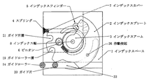
インデックスベースに樹立したインデックス軸に対してインデックスプレートおよび回動軸を軸架し、該回動軸にインデックスアームを固着し、インデックスプレートとインデックスアームの間隙にインデックスフィンガーを介挿し、該インデックスフィンガーに、インデックスアームに係合する突出片と指状の長フィンガーおよび短フィンガーとを設け、インデックスベースに装着されるインデックスカバーに、前記突出片の先端がガイドされてその終端で係止される形状の突出片ガイド溝を設けると共に、インデックスプレートに作動突起を設けて、該作動突起が、インデックスプレートの回動に連れ、前記長フィンガーと短フィンガーの間に入り込みインデックスフィンガーとインデックスアームとを回動させ、弾性体に反発力を蓄積させ、インデックスフィンガーの突出片が突出片ガイド溝の終端に至ったときにその終端で係止され、前記作動突起が短フィンガーを越えてその先端から抜け出しインデックスフィンガーから離脱できるように構成したAs a good example for ensuring that the repulsive force is accumulated in the elastic body at the initial stage of the opening process of the
An index plate and a pivot shaft are mounted on the index shaft established on the index base, an index arm is fixed to the pivot shaft, an index finger is inserted in the gap between the index plate and the index arm, and the index finger is attached to the index finger. The protruding piece that engages the index arm and the finger-like long and short fingers are provided, and the tip of the protruding piece is guided and locked at the end by the index cover mounted on the index base. Protruding piece guide grooves are provided, and an operating projection is provided on the index plate. The operating projection enters between the long finger and the short finger as the index plate rotates, causing the index finger and index arm to rotate. Accumulate repulsive force in elastic Allowed, locked at its end when the protruding piece of the index finger reaches the end of the projecting part guide groove, wherein the actuating projection is configured to be detached from the index finger escape from the tip beyond the short fingers
閉扉行程の終期において反発力が徐々に解放されるようにするため、本発明では次の構成を採用した。
回動軸にダンパー28を連結した。In order to gradually release the repulsive force at the end of the closing process, the present invention adopts the following configuration.
A damper 28 was connected to the rotating shaft.
請求項1に記載した発明においては、外方軌道の左右方向の長さが内方軌道の左右方向の長さよりも長くなるように構成されている。すなわち添付の図20でいうと、外方軌道29の左右方向の長さs1の長さが内方軌道11のs2の長さより長くなっている。開扉行程の初期において、図で白丸の位置にあった各ガイドローラー14が距離s2だけ左方向に移動すると、各ガイドローラー14は図の下向きにh2とh1だけ移動することになる。
その移動の当初においては、中央から遠い方のガイドローラー14は直線短軌道18にあって下向きの移動はなく、その間、中央に近い方のガイドローラー14のみが下向きに移動するため、扉1の左端面のみが扉2の右端面から下向きに離間する。ガイドローラー14が直線短軌道18から外方軌道29へ移るとその下向きの移動距離は中央に近い方のガイドローラー14の下向きの移動距離より短いから扉1は徐々に角度を変えて扉2に重なるように近付いていく。その後、左のガイドローラー14も右のガイドローラー14も共に直線軌道17に導かれ、扉1は扉2と深く重なる位置に移動して行く。In the invention described in
At the beginning of the movement, the guide roller 14 far from the center is on the straight short track 18 and does not move downward. During this time, only the guide roller 14 closer to the center moves downward. Only the left end surface is spaced downward from the right end surface of the
以上の作用は、内方軌道と外方軌道の左右方向の長さを異ならせるという簡単な構成によって達成される。複雑な機構や高剛性の材料など使用する必要がない。しかも、扉には一方向の手動の操作力を加えるだけでよい。
なお、この発明は、一方の扉が他方の扉の前面と面一になるフラットドアについても、一方の扉が機枠の前面と面一になるフラットドアについても適用できる。The above operation is achieved by a simple configuration in which the lengths of the inner track and the outer track in the left-right direction are different. There is no need to use complicated mechanisms or highly rigid materials. Moreover, it is only necessary to apply a manual operating force in one direction to the door.
The present invention can also be applied to a flat door in which one door is flush with the front surface of the other door, and a flat door in which one door is flush with the front surface of the machine frame.
請求項2に記載した発明においては、扉の移動をガイドするガイドローラーが扉の横幅の半分を越える長さとしてあるから、その移動が横幅の半分以下の場合に比べてずっとスムーズに行われるようになる。そして、開扉時または閉扉時に従来例においては扉の下端部がふらつくものが多かったが、本発明ではそのふらつきを効果的に抑制することができた。また、ガイド軌道の直線部分(直線軌道)を一本にしその両端辺に内方軌道と直線短軌道を連結した外方軌道とを設けているから、直線軌道は両方の扉で交互に利用することができる。すなわち、右方の扉を左方の扉に重ねるときには、右方の内方軌道と直線短軌道を連結した外方軌道を使い、左方の扉を右方の扉に重ねるときには、左方の内方軌道と直線短軌道を連結した外方軌道を使えばよいから、装置がコンパクトになり部品点数を減らし製作費を低減することができる。 In the invention described in
請求項3に記載した発明においては、インデックスプレートに弾性体を連係させて、扉の開扉行程の初期のインデックスプレートの回動に伴ない反発力が蓄積され、蓄積された反発力が扉の閉扉行程の終期に解放されるように構成されている。それ故、前記の終期において引き込むまたは押し込む方向の特段の手動の操作力などを必要とせずに、扉を左方または右方にスライドさせる一方向の手動の操作力のみによって、扉を面一になる位置に常に確実に引き込むことができる。
従来例のように、扉にかかる重力を利用することもないから、扉を高みに持ち上げる操作力も不要となる。In the invention described in
Unlike the conventional example, since the gravity applied to the door is not used, an operation force for lifting the door to a height is not required.
請求項4に記載した発明においては、ガイドローラーとガイド片が並べて支持板に取り付けられ、両者が軌道に沿って並んで移動するように構成されているから、ガイドローラーが一個だけの場合に比べて支持板の移動が、ひいては扉の移動が非常に安定し確実なものとなる。 In the invention described in claim 4, the guide roller and the guide piece are arranged side by side and attached to the support plate, and both are moved side by side along the track, so that compared to the case where there is only one guide roller. Therefore, the movement of the support plate, and thus the movement of the door, is very stable and reliable.
請求項5に記載した発明においては、インデックス軸、作動突起を設け弾性体を連係させたインデックスプレート、インデックスアームを固着した回動軸、突出片と指状の長フィンガーおよび短フィンガー等から成るインデックスフィンガーおよび突出片ガイド溝を設けたインデックスカバーが特定の構造を持ち、巧みに組み合わされているため、前記作動突起が、インデックスプレートの回動に連れ、前記長フィンガーと短フィンガーの間に入り込みインデックスフィンガーとインデックスアームとを回動させて、弾性体に反発力を蓄積させ、インデックスフィンガーの突出片が突出片ガイド溝の終端に至ったときにその終端で係止され、前記作動突起が短フィンガーを押圧し、その先端から抜け出して回動を続けるという動作を滑らかに安定して確実に行わせることができる。
なお、閉扉行程の終期においては、前記の構成によりこれらの動作が逆向きに行われる。In the invention described in claim 5, an index plate, an index plate provided with operating projections and linked with an elastic body, a pivot shaft to which an index arm is fixed, an index piece composed of a protruding piece and finger-like long and short fingers, etc. Since the index cover provided with fingers and protruding piece guide grooves has a specific structure and is skillfully combined, the operating projection enters between the long finger and the short finger as the index plate rotates. The finger and the index arm are rotated to accumulate the repulsive force in the elastic body. When the protruding piece of the index finger reaches the end of the protruding piece guide groove, it is locked at the end, and the operating protrusion is a short finger. Smooth the movement of pressing and pushing from the tip to continue turning Constant and can be reliably performed.
In the final stage of the door closing process, these operations are performed in the reverse direction by the above-described configuration.
請求項5に記載した発明においては、回動軸32がダンパーに連結されているから、閉扉行程の終期において、扉がゆっくりと面一になる位置に近付き、そこに確実に引き込まれ停止する。 In the invention described in claim 5, since the rotating shaft 32 is connected to the damper, at the end of the door closing process, the door slowly approaches a position where it is flush with the door, and is reliably pulled in and stopped.
左方または右方にスライドして、開扉時に開扉される一方の扉が他方の扉または機枠の前面に重なり、閉扉時には前記一方の扉が他方の扉または機枠の前面と面一になるフラットドアの開閉機構において、インデックスベースに樹立したインデックス軸に対してインデックスプレートおよび回動軸を軸架し、該回動軸にインデックスアームを固着し、インデックスプレートとインデックスアームの間隙にインデックスフィンガーを介挿し、該インデックスフィンガーに、インデックスアームに係合する突出片と指状の長フィンガーおよび短フィンガーとを設け、インデックスベースに装着されるインデックスカバーに、前記突出片の先端がガイドされてその終端で係止される形状の突出片ガイド溝を設けると共に、インデックスプレートに作動突起を設けて、該作動突起が、インデックスプレートの回動に連れ、前記長フィンガーと短フィンガーの間に入り込みインデックスフィンガーとインデックスアームとを回動させ、弾性体に反発力を蓄積させ、インデックスフィンガーの突出片が突出片ガイド溝の終端に至ったときにその終端で係止され、前記作動突起が短フィンガーを越えてその先端から抜け出しインデックスフィンガーから離脱できるように構成する。 Slide left or right and one door that opens when the door is opened overlaps the front of the other door or machine frame, and when the door is closed, the one door is flush with the front of the other door or machine frame. In the open / close mechanism of the flat door, the index plate and the pivot shaft are mounted on the index shaft established on the index base, the index arm is fixed to the pivot shaft, and the index plate is indexed in the gap between the index plate and the index arm. A finger is inserted, the index finger is provided with a protruding piece that engages with the index arm, and a finger-like long finger and a short finger, and the tip of the protruding piece is guided by an index cover that is attached to the index base. Protruding piece guide groove shaped to be locked at the end is provided, and it is made on the index plate. As the index plate rotates, the operating protrusion enters between the long finger and the short finger, rotates the index finger and the index arm, and accumulates a repulsive force in the elastic body. When the projecting piece reaches the end of the projecting piece guide groove, the projecting piece is locked at the end, so that the operating projection can be pulled out from the tip beyond the short finger and detached from the index finger.
添付図面を参照しながら、本発明の実施例について説明する。
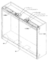
図1から図3は、扉1、扉2と本発明の関係を示す斜視図で、図1は両扉が閉扉状態にあるときの図、図2は扉1が開き始めたときの図、図3は扉1のガイド部が直線軌道17に入り扉1が扉2と平行状態になったときの図である。
図4はガイド軌道10の平面図である。
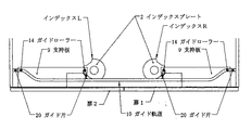
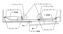
図5から図7は扉1、2とインデックスR、Lとガイド軌道10との関係を示す模式図であり、図5は両扉が閉扉状態にあるときの図、図6は扉1が開き始めたときの図、図7はガイド部が直線軌道17に入り扉1が扉2と平行状態になって全開したときの図である。Embodiments of the present invention will be described with reference to the accompanying drawings.
1 to 3 are perspective views showing the relationship between the
FIG. 4 is a plan view of the guide track 10.
5 to 7 are schematic views showing the relationship between the
図8から図12はインデックスプレート2の回動に始まる開扉行程の初期における作動を逐次的に示す平面図であり、図8は作動突起26が長フィンガー22と短フィンガー23の間に入り、突出片24を介しインデックスアーム3を回動させ始めるときの図、図9はその回動がさらに進み突出片24が突出片ガイド溝25の終端に達したときの図、図10は作動突起26がインデックスフィンガー5を少し傾け突出片24を突出片ガイド溝25の終端に係止させたときの図、図11は作動突起26がインデックスフィンガー5から離れて回動を続け、ガイドローラー14がガイドローラー溝19から離脱し、インデックスフィンガー5とインデックスアーム3は停止しているときの図、図12は中央から遠い方のガイド部のガイド片20が逃がし溝33を通り抜けるときの図である。 8 to 12 are plan views sequentially showing the operation in the initial stage of the door opening process starting from the rotation of the
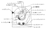
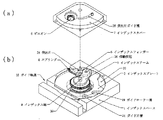
図13、図14は反発力の蓄積、解放に関与する部分の構成を示す図であり、いずれも、(a)はインデックスカバー側の構成を(b)はインデックスカバーが装着されるインデックスベース側の構成を示しており、図13は右斜視図、図14は左斜視図である。
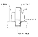
図15、図16はガイド部を示し、図15はその正面図、図16はその側面図である。図17はダンパー28の斜視図である。FIGS. 13 and 14 are diagrams showing the configuration of the part involved in the accumulation and release of the repulsive force, both of which show (a) the configuration on the index cover side and (b) the index base side on which the index cover is mounted. FIG. 13 is a right perspective view, and FIG. 14 is a left perspective view.
15 and 16 show the guide portion, FIG. 15 is a front view thereof, and FIG. 16 is a side view thereof. FIG. 17 is a perspective view of the damper 28.
図18は、回動軸32を固着したインデックスアーム3とインデックスフィンガー5とインデックスプレート2との配設位置関係を示す分解図であり図19は図18にさらにスプリング4とインデックスベース1を加えた分解図である。
図20は一方向の手動の操作力を加えるだけで、隣り合う扉または機枠の端面に当接させることなく扉を開閉させることのできるようにする構成を示した模式図である。
なお、以上の図面は、扉1および扉2が垂直面内を移動する場合について記載されているが、若干の設計変更を加えれば、本発明は扉1および扉2が水平面内等を移動する場合についても(その具体例は省略するが、)適用できるものである。18 is an exploded view showing an arrangement positional relationship among the
FIG. 20 is a schematic diagram showing a configuration in which a door can be opened and closed without applying contact to an adjacent door or an end face of a machine frame only by applying a manual operation force in one direction.
In addition, although the above drawings are described about the case where the
請求項1に記載された発明の実施例について説明する。
支持板9の先端縁に扉1から等距離のところに位置する二つのガイド部は、図では支持板9の下側に付けられている(図3参照。)が、支持板9の上側または横側に付けるようにする設計変更も可能である。その場合には、前記ガイド部をガイドするガイド軌道10もその変更に対応してその位置を変える。
機枠に設けるガイド軌道10の設計にあたっては、特に、図20に示すh1がゼロである間にh2が(扉1の左端面を扉2の右端面から引き離すのに)十分なだけの距離になるような寸法にする等のことを考慮して、直線短軌道18その他の長さを定め、内方軌道11はインデックスプレートの周縁に合致する形にカーヴさせる。各軌道の合流点を滑らかに接続するように形成するのは、いうまでもない。An embodiment of the invention described in
Two guide portions located at the same distance from the
In designing the guide track 10 provided in the machine frame, in particular, h2 should be a sufficient distance (to separate the left end face of the
請求項2に記載された発明の実施例について説明する。
二つのガイド部間の距離は長ければ長いほど扉の移動は安定したものとなるが、直線軌道17は一本なのであるから、それを定めるにあたっては、図7に示すように、扉1の全開時において、扉1の二つのガイド部の間に扉2のインデックスLが位置する程度の長さにすることが一般的な設計といえる。
軌道の形について、図では断面凹型のものを示したが、これに限られることなく、鉄道線路のような断面のものにし、ガイドローラー14等をそれに対応する形にしても良いことは勿論である。An embodiment of the invention described in
The longer the distance between the two guide portions, the more stable the movement of the door. However, since there is only one linear track 17, the
In the figure, the shape of the track is shown with a concave cross section. However, the shape of the track is not limited to this, and the shape of the track may be a cross section like a railroad track, and the guide roller 14 or the like may have a corresponding shape. is there.
さらに、扉の平行移動を安定させる上で有効な対策としては、次の二つのものが考えられる。
まず、扉の平行移動を不安定にさせる要因について説明する。
開扉時に、中央から遠い方のガイド部のガイドローラー14が内方軌道11と直線軌道17との合流点を通過する時に、扉1の右縁部に直角方向の力が加わると、扉1の直線軌道17に対する平行移動が不安定になる。換言すると、ガイドローラー14とガイド片20を結ぶ線と直線軌道17の中心線の二つの線の成す角度が、ゼロでなくなり、平行した移動ができなくなる。その原因は、図20等から容易に見て取れるように、直線軌道17の溝の幅(同図でいうと、直線軌道17の溝の中心線に直角な方向の長さ)が合流点において急に広くなり、その広くなったところにガイドローラー14が入り込んでしまうところにあることが分かった。Furthermore, the following two measures can be considered as effective measures for stabilizing the parallel movement of the door.
First, factors that make the parallel movement of the door unstable will be described.
When a right angle force is applied to the right edge of the
叙上の現象を生じさせない対策としては、直線軌道17の溝の深さを内方軌道11の溝の深さよりも少し深くすること(図11参照。)が考えられた。そして、中央から遠い方のガイド部のガイドローラー14とガイド片20をその深さに対応する長さにした。
そうにすれば、ガイドローラー14は合流点の広くなったところに入り込まずに、直線軌道17にのみ導かれて移動するようになる。なお、この対策は、ガイド部がガイドローラー14のみで構成されている場合にも効果がある。
また、前記の不安定さを軽減する対策としては、ガイドローラー14とガイド片20の離間間隔を長くとることが考えられた。そうにすれば、先行するガイドローラー14が前記の広くなったところに入り込んだとしても、ガイドローラー14とガイド片20を結ぶ線と直線軌道17の中心線の二つの線の成す角度を(前記離間間隔が短い場合よりも)小さくすることができる。角度が小さくなると(すなわち、前記の角度がゼロに近くなると)、移動の不安定さが軽減される。As a countermeasure not to cause the above phenomenon, it was considered that the groove depth of the straight track 17 is made slightly deeper than the groove depth of the inner track 11 (see FIG. 11). And the guide roller 14 and the
If it does so, the guide roller 14 will be introduced only to the linear track | orbit 17 and will move, without entering into the place where the confluence | merging point became wide. This measure is also effective when the guide portion is composed of only the guide roller 14.
Further, as a measure for reducing the instability, it has been considered to increase the distance between the guide roller 14 and the
請求項3に記載された発明の実施例について説明する。
円板状のインデックスプレート2の周縁に設けるガイドローラー溝19は、図8から図12および図18、図19に示すように、中央に近い方のガイド部のガイドローラー14が嵌入し易く、また抜け出し易くなるような形状にする。
インデックスプレート2に連係される弾性体としては、図では引張りスプリング4を示したが、少し設計を変えて、圧縮スプリングとしても良いし、滑車やワイヤーに連なる重りを用いることも、内蔵ガスを圧縮し反発力を生じさせるガススプリングなどを用いるようにすることもできる。
図8から図14に示したスプリング4は、図19および図13、図14に明示されているように、インデックスベース1と回動軸32に設けられた係留片30との間に張架され、扉1の開扉時に、回動軸32に固着されたインデックスアーム3の回動に伴なって反発力が蓄積されるように設計されている。
弾性体としてスプリング以外の物を使う場合には、それに適した設計変更が行われなければならない。An embodiment of the invention described in
As shown in FIGS. 8 to 12, 18 and 19, the guide roller groove 19 provided on the peripheral edge of the disk-shaped
As the elastic body linked to the
The spring 4 shown in FIGS. 8 to 14 is stretched between the
When an object other than a spring is used as an elastic body, a design change suitable for it must be made.
請求項4に記載された発明の実施例について説明する。
ガイド部の詳細は図15および図16に記載した。図では支持板9の端部にガイド部が設けられ、リンク12とガイドローラー14がリンクシャフト13に軸支されている。
ガイド片20は、扉1の移動を導くガイドローラー14が安定して確実に軌道に沿って移動できるようなものとする。インデックスプレート2に設けるガイド片溝21の形状は、前述したガイドローラー溝19の形状を参考にして定めることができる。ガイド片20の配置については、中央に近い方のガイド部においては端部のガイドローラー14の手前に配置し、中央から遠い方のガイド部においては端部にガイド片20をその手前にガイドローラー14を配置するのが望ましい。
図では、リンク12の側部に安定ローラー15が取り付けられているが、それにより扉の移動はさらに安定する。また、図8から図12および図18、図19に示すように、内方軌道11と直線軌道17との合流点において直線軌道17側に、食い込み凹部31(図19参照)を設けておけば、ガイドローラー溝19およびガイド片溝21の深さを深くとることができるから、ガイド片20およびガイドローラー14との係合がさらに安定する。An embodiment of the invention described in claim 4 will be described.
Details of the guide portion are shown in FIGS. 15 and 16. In the figure, a guide portion is provided at the end of the support plate 9, and the link 12 and the guide roller 14 are pivotally supported by the link shaft 13.
The
In the figure, although the
請求項5に記載された発明の実施例について説明する。
請求項5の各構成部分は、次の作動を完遂するように造られる。
開扉行程は図8から始まる。
図8において、インデックスプレート2はガイドローラー14の時計方向の回動に連れて同方向に回動しスプリング4を引き伸ばし始める。すなわち、インデックスプレート2に固定した作動突起26は、長フィンガー22と短フィンガー23の間に入り込みインデックスフィンガー5を押し動かし、インデックスフィンガー5の突出片24は、インデックスカバー7の突出片ガイド溝25に導かれながらインデックスアーム3を時計方向に回動させる。
これに関与する構成部分の設計にあたっては、叙上の回動がスムーズに安定して行えるよう、細心の注意が払われなければならない。An embodiment of the invention described in claim 5 will be described.
Each component of claim 5 is constructed to complete the following operations.
The door opening process starts from FIG.
In FIG. 8, the
In designing the components involved in this, great care must be taken to ensure that the above described rotation can be performed smoothly and stably.
図9は前記の回動が進み、突出片24が突出片ガイド溝25の終端まで来たところを示す。作動突起26はなおも進んでインデックスフィンガー5を少し傾けさせ、突出片24を突出片ガイド溝25の終端に係止させる。スプリング4はこの時に至るまで引き伸ばされ反発力を蓄積する。
図10は作動突起26がさらに進み短フィンガー23の先端を越えたところを示す。インデックスアーム3とインデックスフィンガー5はこの時点で回動を止めその位置に止まる。FIG. 9 shows the state where the rotation has progressed and the protruding piece 24 has reached the end of the protruding piece guide groove 25. The actuating projection 26 still proceeds to tilt the index finger 5 a little to lock the protruding piece 24 to the end of the protruding piece guide groove 25. At this time, the spring 4 is stretched and accumulates a repulsive force.
FIG. 10 shows the actuating protrusion 26 moving further and beyond the tip of the short finger 23. The
図11は、その後もインデックスプレート2が回動を続け、ガイドローラー14がインデックスプレート2のガイドローラー溝19から離れたところを示す。ここでインデックスプレート2の回動は一時中止し、ガイドローラー14はガイド軌道10の直線軌道17に入り左方へ進む。
図12は中央から遠い方のガイド部がインデックスRを通り抜けたときの状態を示す。その場合において、中央から遠い方のガイド部のガイドローラー14は、図示の例では、ガイドローラー溝19に続いてインデックスプレート2の周縁に設けられた逃がし溝33に入り、インデックスプレート2をさらに回動させ、その後にインデックスRから離れるようになっている。
以上の行程を経て、扉1は扉2に重なり開扉される。FIG. 11 shows that the
FIG. 12 shows a state in which the guide portion far from the center passes through the index R. In that case, in the illustrated example, the guide roller 14 of the guide portion far from the center enters the
Through the above process, the
閉扉行程においては、叙上の過程が逆向きに行われる。
すなわち、扉1を左方に動かすと、中央から遠い方のガイド部がインデックスプレート2を回動させながら通り抜け、引き続いて中央に近い方のガイド部がインデックスRにさしかかる。その時点の状態は図11に示されている。次いでガイドローラー14がガイドローラー溝19の右壁を押してインデックスプレート2をさらに回動させる。その回動が進み作動突起26が長フィンガー22を押すと、突出片24が突出片ガイド溝25の係止から外れ、同時に作動突起26が長フィンガー22と短フィンガー23の間に入り込む。In the closing process, the above process is performed in the reverse direction.
That is, when the
そして、拘束を解かれたインデックスアーム3はスプリング4に蓄積された反発力によって反時計方向に回動する。インデックスアーム3のその回動はインデックスフィンガー5および作動突起26を介してインデックスプレート2に伝えられ、インデックスプレート2は、ガイドローラ溝19に入っているガイドローラー14を反時計方向に(インデックス軸8を中心に)回動させるから、扉1は面一になる位置に確実に引き戻される。
上記の各構成部分は、言うまでもなく、叙上の作動が確実に行われるように設計されなければならない。Then, the
Each of the above components must, of course, be designed to ensure that the described operation is performed.
請求項6に記載された発明の実施例について説明する。
図17、図18または図19によれば、ダンパー28は、ピニオン6と歯車27を介して、該歯車27を固定した回動軸32に連結されている。
しかし、連結の態様はこれのみに限らず他の公知の連結機構を用いても良いことは勿論である。また、ダンパーにしても、閉扉行程の終期において反発力が徐々に解放されるような機能をもつものであればよく、各種の公知のものが用いられる。An embodiment of the invention described in claim 6 will be described.
According to FIG. 17, FIG. 18 or FIG. 19, the damper 28 is connected via the pinion 6 and the gear 27 to the rotating shaft 32 to which the gear 27 is fixed.
However, the connection mode is not limited to this, and other known connection mechanisms may be used. Also, the damper may be any damper as long as it has a function of gradually releasing the repulsive force at the end of the closing process, and various known ones are used.
1 インデックスベース
2 インデックスプレート
3 インデックスアーム
4 スプリング
5 インデックスフィンガー
7 インデックスカバー
8 インデックス軸
9 支持板
10 ガイド軌道
11 内方軌道
12 リンク
14 ガイドローラー
17 直線軌道
18 直線短軌道
19 ガイドローラー溝
20 ガイド片
21 ガイド片溝
22 長フィンガー
23 短フィンガー
24 突出片
25 突出片ガイド溝
26 作動突起
28 ダンパー
29 外方軌道DESCRIPTION OF
Claims (4)
Priority Applications (1)
| Application Number | Priority Date | Filing Date | Title |
|---|---|---|---|
| JP2008101916A JP4200468B1 (en) | 2008-03-13 | 2008-03-13 | Flat door opening and closing mechanism |
Applications Claiming Priority (1)
| Application Number | Priority Date | Filing Date | Title |
|---|---|---|---|
| JP2008101916A JP4200468B1 (en) | 2008-03-13 | 2008-03-13 | Flat door opening and closing mechanism |
Publications (2)
| Publication Number | Publication Date |
|---|---|
| JP4200468B1 true JP4200468B1 (en) | 2008-12-24 |
| JP2009221825A JP2009221825A (en) | 2009-10-01 |
Family
ID=40239537
Family Applications (1)
| Application Number | Title | Priority Date | Filing Date |
|---|---|---|---|
| JP2008101916A Expired - Fee Related JP4200468B1 (en) | 2008-03-13 | 2008-03-13 | Flat door opening and closing mechanism |
Country Status (1)
| Country | Link |
|---|---|
| JP (1) | JP4200468B1 (en) |
Cited By (3)
| Publication number | Priority date | Publication date | Assignee | Title |
|---|---|---|---|---|
| IT201600098928A1 (en) * | 2016-10-03 | 2018-04-03 | Caimi S R L | DEVICE FOR HANDLING SLIDING DOORS AND FURNITURE ARTICLE INCLUDING THIS DEVICE |
| US10724282B2 (en) * | 2016-01-18 | 2020-07-28 | Daiwa Industries Ltd. | Opening and closing mechanism for opening and closing bodies |
| US20220160146A1 (en) * | 2020-11-25 | 2022-05-26 | Hussmann Corporation | Merchandiser including track door system |
Families Citing this family (1)
| Publication number | Priority date | Publication date | Assignee | Title |
|---|---|---|---|---|
| KR101249976B1 (en) * | 2012-11-23 | 2013-04-03 | (주)지씨아이 | Opening and closing apparatus of sliding door |
-
2008
- 2008-03-13 JP JP2008101916A patent/JP4200468B1/en not_active Expired - Fee Related
Cited By (6)
| Publication number | Priority date | Publication date | Assignee | Title |
|---|---|---|---|---|
| US10724282B2 (en) * | 2016-01-18 | 2020-07-28 | Daiwa Industries Ltd. | Opening and closing mechanism for opening and closing bodies |
| IT201600098928A1 (en) * | 2016-10-03 | 2018-04-03 | Caimi S R L | DEVICE FOR HANDLING SLIDING DOORS AND FURNITURE ARTICLE INCLUDING THIS DEVICE |
| WO2018065871A1 (en) * | 2016-10-03 | 2018-04-12 | Caimi S.R.L. | Device for moving sliding doors and article of furniture comprising such a device |
| CN110023577A (en) * | 2016-10-03 | 2019-07-16 | 卡伊米有限责任公司 | For the device of moving sliding doors and the article of furniture including this device |
| US20220160146A1 (en) * | 2020-11-25 | 2022-05-26 | Hussmann Corporation | Merchandiser including track door system |
| US11864669B2 (en) * | 2020-11-25 | 2024-01-09 | Hussmann Corporation | Merchandiser including track door system |
Also Published As
| Publication number | Publication date |
|---|---|
| JP2009221825A (en) | 2009-10-01 |
Similar Documents
| Publication | Publication Date | Title |
|---|---|---|
| CN109654112B (en) | Rotating shaft module of folding device | |
| US7758134B2 (en) | Drawer fixing apparatus | |
| TWI492734B (en) | Drinks for containers | |
| JP4726734B2 (en) | Slider for slide fastener | |
| JP4200468B1 (en) | Flat door opening and closing mechanism | |
| WO2015083619A1 (en) | Lock mechanism and opening/closing device | |
| JP2005290769A (en) | Member holding device | |
| JP2007107301A (en) | Guide device for sliding door | |
| CN107095493B (en) | Slide rail with internal contraction movable rail | |
| JP2012001916A (en) | Folding door | |
| TW201921221A (en) | A hinge module for foldable type devices having a fourth sliding portion at an end of an intermediate transmission member slidably positioned on a second sliding portion of a transmission member to allow the transmission member and a transmission plate to move in opposite directions | |
| CN103243992A (en) | Door leaf fixer | |
| JP5517347B2 (en) | Door stopper device | |
| JP3180645U (en) | Bi-directional drawer slide rail and drawer structure using the same | |
| JP2009154788A (en) | Locking part structure of fuel lid | |
| JP2007032177A (en) | Furniture with flat sliding door | |
| JP5032675B2 (en) | Door opening / closing unit | |
| JP2003120115A (en) | Traveling mechanism, door sheave mechanism and sliding door | |
| JP2007204093A (en) | Box body | |
| JP5724253B2 (en) | Door opener | |
| TWM555155U (en) | Pressing type buckle apparatus | |
| JP6671796B2 (en) | Seat truck | |
| KR20100125552A (en) | Locking apparatus for sliding plate of sliding handphone | |
| WO2019130604A1 (en) | Door opening device, door opening/closing device, and refrigerator | |
| JP2013127174A (en) | Auxiliary mechanism of sliding door |
Legal Events
| Date | Code | Title | Description |
|---|---|---|---|
| TRDD | Decision of grant or rejection written | ||
| A01 | Written decision to grant a patent or to grant a registration (utility model) |
Free format text: JAPANESE INTERMEDIATE CODE: A01 Effective date: 20080916 |
|
| A01 | Written decision to grant a patent or to grant a registration (utility model) |
Free format text: JAPANESE INTERMEDIATE CODE: A01 |
|
| A61 | First payment of annual fees (during grant procedure) |
Free format text: JAPANESE INTERMEDIATE CODE: A61 Effective date: 20080924 |
|
| R150 | Certificate of patent or registration of utility model |
Free format text: JAPANESE INTERMEDIATE CODE: R150 |
|
| FPAY | Renewal fee payment (event date is renewal date of database) |
Free format text: PAYMENT UNTIL: 20111017 Year of fee payment: 3 |
|
| FPAY | Renewal fee payment (event date is renewal date of database) |
Free format text: PAYMENT UNTIL: 20111017 Year of fee payment: 3 |
|
| FPAY | Renewal fee payment (event date is renewal date of database) |
Free format text: PAYMENT UNTIL: 20121017 Year of fee payment: 4 |
|
| LAPS | Cancellation because of no payment of annual fees |