JP4197433B2 - Lancet integrated sensor and measuring device for lancet integrated sensor - Google Patents
Lancet integrated sensor and measuring device for lancet integrated sensor Download PDFInfo
- Publication number
- JP4197433B2 JP4197433B2 JP2002557282A JP2002557282A JP4197433B2 JP 4197433 B2 JP4197433 B2 JP 4197433B2 JP 2002557282 A JP2002557282 A JP 2002557282A JP 2002557282 A JP2002557282 A JP 2002557282A JP 4197433 B2 JP4197433 B2 JP 4197433B2
- Authority
- JP
- Japan
- Prior art keywords
- lancet
- integrated sensor
- measuring device
- sensor
- integrated
- Prior art date
- Legal status (The legal status is an assumption and is not a legal conclusion. Google has not performed a legal analysis and makes no representation as to the accuracy of the status listed.)
- Expired - Fee Related
Links
Images


Classifications
-
- A—HUMAN NECESSITIES
- A61—MEDICAL OR VETERINARY SCIENCE; HYGIENE
- A61B—DIAGNOSIS; SURGERY; IDENTIFICATION
- A61B5/00—Measuring for diagnostic purposes; Identification of persons
- A61B5/0002—Remote monitoring of patients using telemetry, e.g. transmission of vital signals via a communication network
- A61B5/0004—Remote monitoring of patients using telemetry, e.g. transmission of vital signals via a communication network characterised by the type of physiological signal transmitted
- A61B5/0006—ECG or EEG signals
-
- A—HUMAN NECESSITIES
- A61—MEDICAL OR VETERINARY SCIENCE; HYGIENE
- A61B—DIAGNOSIS; SURGERY; IDENTIFICATION
- A61B5/00—Measuring for diagnostic purposes; Identification of persons
- A61B5/15—Devices for taking samples of blood
- A61B5/150007—Details
- A61B5/150015—Source of blood
- A61B5/150022—Source of blood for capillary blood or interstitial fluid
-
- A—HUMAN NECESSITIES
- A61—MEDICAL OR VETERINARY SCIENCE; HYGIENE
- A61B—DIAGNOSIS; SURGERY; IDENTIFICATION
- A61B5/00—Measuring for diagnostic purposes; Identification of persons
- A61B5/15—Devices for taking samples of blood
- A61B5/150007—Details
- A61B5/150206—Construction or design features not otherwise provided for; manufacturing or production; packages; sterilisation of piercing element, piercing device or sampling device
- A61B5/150259—Improved gripping, e.g. with high friction pattern or projections on the housing surface or an ergonometric shape
-
- A—HUMAN NECESSITIES
- A61—MEDICAL OR VETERINARY SCIENCE; HYGIENE
- A61B—DIAGNOSIS; SURGERY; IDENTIFICATION
- A61B5/00—Measuring for diagnostic purposes; Identification of persons
- A61B5/15—Devices for taking samples of blood
- A61B5/150007—Details
- A61B5/150374—Details of piercing elements or protective means for preventing accidental injuries by such piercing elements
- A61B5/150381—Design of piercing elements
- A61B5/150412—Pointed piercing elements, e.g. needles, lancets for piercing the skin
-
- A—HUMAN NECESSITIES
- A61—MEDICAL OR VETERINARY SCIENCE; HYGIENE
- A61B—DIAGNOSIS; SURGERY; IDENTIFICATION
- A61B5/00—Measuring for diagnostic purposes; Identification of persons
- A61B5/15—Devices for taking samples of blood
- A61B5/150007—Details
- A61B5/150374—Details of piercing elements or protective means for preventing accidental injuries by such piercing elements
- A61B5/150381—Design of piercing elements
- A61B5/150503—Single-ended needles
- A61B5/150519—Details of construction of hub, i.e. element used to attach the single-ended needle to a piercing device or sampling device
-
- A—HUMAN NECESSITIES
- A61—MEDICAL OR VETERINARY SCIENCE; HYGIENE
- A61B—DIAGNOSIS; SURGERY; IDENTIFICATION
- A61B5/00—Measuring for diagnostic purposes; Identification of persons
- A61B5/15—Devices for taking samples of blood
- A61B5/150007—Details
- A61B5/150374—Details of piercing elements or protective means for preventing accidental injuries by such piercing elements
- A61B5/150534—Design of protective means for piercing elements for preventing accidental needle sticks, e.g. shields, caps, protectors, axially extensible sleeves, pivotable protective sleeves
- A61B5/150541—Breakable protectors, e.g. caps, shields or sleeves, i.e. protectors separated destructively, e.g. by breaking a connecting area
- A61B5/150564—Protectors removed by pulling or pushing
-
- A—HUMAN NECESSITIES
- A61—MEDICAL OR VETERINARY SCIENCE; HYGIENE
- A61B—DIAGNOSIS; SURGERY; IDENTIFICATION
- A61B5/00—Measuring for diagnostic purposes; Identification of persons
- A61B5/15—Devices for taking samples of blood
- A61B5/150007—Details
- A61B5/150374—Details of piercing elements or protective means for preventing accidental injuries by such piercing elements
- A61B5/150534—Design of protective means for piercing elements for preventing accidental needle sticks, e.g. shields, caps, protectors, axially extensible sleeves, pivotable protective sleeves
- A61B5/150694—Procedure for removing protection means at the time of piercing
- A61B5/150717—Procedure for removing protection means at the time of piercing manually removed
-
- A—HUMAN NECESSITIES
- A61—MEDICAL OR VETERINARY SCIENCE; HYGIENE
- A61B—DIAGNOSIS; SURGERY; IDENTIFICATION
- A61B5/00—Measuring for diagnostic purposes; Identification of persons
- A61B5/15—Devices for taking samples of blood
- A61B5/150007—Details
- A61B5/150374—Details of piercing elements or protective means for preventing accidental injuries by such piercing elements
- A61B5/150534—Design of protective means for piercing elements for preventing accidental needle sticks, e.g. shields, caps, protectors, axially extensible sleeves, pivotable protective sleeves
- A61B5/150694—Procedure for removing protection means at the time of piercing
- A61B5/150725—Procedure for removing protection means at the time of piercing removal procedure linked to further actions, e.g. cocking of the piercing device, which indicate that the piercing device is used or tempered
-
- A—HUMAN NECESSITIES
- A61—MEDICAL OR VETERINARY SCIENCE; HYGIENE
- A61B—DIAGNOSIS; SURGERY; IDENTIFICATION
- A61B5/00—Measuring for diagnostic purposes; Identification of persons
- A61B5/15—Devices for taking samples of blood
- A61B5/151—Devices specially adapted for taking samples of capillary blood, e.g. by lancets, needles or blades
- A61B5/15101—Details
- A61B5/15103—Piercing procedure
- A61B5/15107—Piercing being assisted by a triggering mechanism
- A61B5/15113—Manually triggered, i.e. the triggering requires a deliberate action by the user such as pressing a drive button
-
- A—HUMAN NECESSITIES
- A61—MEDICAL OR VETERINARY SCIENCE; HYGIENE
- A61B—DIAGNOSIS; SURGERY; IDENTIFICATION
- A61B5/00—Measuring for diagnostic purposes; Identification of persons
- A61B5/15—Devices for taking samples of blood
- A61B5/151—Devices specially adapted for taking samples of capillary blood, e.g. by lancets, needles or blades
- A61B5/15101—Details
- A61B5/15115—Driving means for propelling the piercing element to pierce the skin, e.g. comprising mechanisms based on shape memory alloys, magnetism, solenoids, piezoelectric effect, biased elements, resilient elements, vacuum or compressed fluids
- A61B5/15117—Driving means for propelling the piercing element to pierce the skin, e.g. comprising mechanisms based on shape memory alloys, magnetism, solenoids, piezoelectric effect, biased elements, resilient elements, vacuum or compressed fluids comprising biased elements, resilient elements or a spring, e.g. a helical spring, leaf spring, or elastic strap
-
- A—HUMAN NECESSITIES
- A61—MEDICAL OR VETERINARY SCIENCE; HYGIENE
- A61B—DIAGNOSIS; SURGERY; IDENTIFICATION
- A61B5/00—Measuring for diagnostic purposes; Identification of persons
- A61B5/15—Devices for taking samples of blood
- A61B5/151—Devices specially adapted for taking samples of capillary blood, e.g. by lancets, needles or blades
- A61B5/15101—Details
- A61B5/15126—Means for controlling the lancing movement, e.g. 2D- or 3D-shaped elements, tooth-shaped elements or sliding guides
- A61B5/1513—Means for controlling the lancing movement, e.g. 2D- or 3D-shaped elements, tooth-shaped elements or sliding guides comprising linear sliding guides
-
- A—HUMAN NECESSITIES
- A61—MEDICAL OR VETERINARY SCIENCE; HYGIENE
- A61B—DIAGNOSIS; SURGERY; IDENTIFICATION
- A61B5/00—Measuring for diagnostic purposes; Identification of persons
- A61B5/15—Devices for taking samples of blood
- A61B5/151—Devices specially adapted for taking samples of capillary blood, e.g. by lancets, needles or blades
- A61B5/15186—Devices loaded with a single lancet, i.e. a single lancet with or without a casing is loaded into a reusable drive device and then discarded after use; drive devices reloadable for multiple use
- A61B5/15188—Constructional features of reusable driving devices
- A61B5/1519—Constructional features of reusable driving devices comprising driving means, e.g. a spring, for propelling the piercing unit
-
- A—HUMAN NECESSITIES
- A61—MEDICAL OR VETERINARY SCIENCE; HYGIENE
- A61B—DIAGNOSIS; SURGERY; IDENTIFICATION
- A61B5/00—Measuring for diagnostic purposes; Identification of persons
- A61B5/15—Devices for taking samples of blood
- A61B5/151—Devices specially adapted for taking samples of capillary blood, e.g. by lancets, needles or blades
- A61B5/15186—Devices loaded with a single lancet, i.e. a single lancet with or without a casing is loaded into a reusable drive device and then discarded after use; drive devices reloadable for multiple use
- A61B5/15188—Constructional features of reusable driving devices
- A61B5/15192—Constructional features of reusable driving devices comprising driving means, e.g. a spring, for retracting the lancet unit into the driving device housing
- A61B5/15194—Constructional features of reusable driving devices comprising driving means, e.g. a spring, for retracting the lancet unit into the driving device housing fully automatically retracted, i.e. the retraction does not require a deliberate action by the user, e.g. by terminating the contact with the patient's skin
-
- A—HUMAN NECESSITIES
- A61—MEDICAL OR VETERINARY SCIENCE; HYGIENE
- A61B—DIAGNOSIS; SURGERY; IDENTIFICATION
- A61B5/00—Measuring for diagnostic purposes; Identification of persons
- A61B5/15—Devices for taking samples of blood
- A61B5/157—Devices characterised by integrated means for measuring characteristics of blood
-
- A—HUMAN NECESSITIES
- A61—MEDICAL OR VETERINARY SCIENCE; HYGIENE
- A61B—DIAGNOSIS; SURGERY; IDENTIFICATION
- A61B2562/00—Details of sensors; Constructional details of sensor housings or probes; Accessories for sensors
- A61B2562/02—Details of sensors specially adapted for in-vivo measurements
- A61B2562/0295—Strip shaped analyte sensors for apparatus classified in A61B5/145 or A61B5/157
-
- A—HUMAN NECESSITIES
- A61—MEDICAL OR VETERINARY SCIENCE; HYGIENE
- A61B—DIAGNOSIS; SURGERY; IDENTIFICATION
- A61B5/00—Measuring for diagnostic purposes; Identification of persons
- A61B5/145—Measuring characteristics of blood in vivo, e.g. gas concentration, pH value; Measuring characteristics of body fluids or tissues, e.g. interstitial fluid, cerebral tissue
- A61B5/14532—Measuring characteristics of blood in vivo, e.g. gas concentration, pH value; Measuring characteristics of body fluids or tissues, e.g. interstitial fluid, cerebral tissue for measuring glucose, e.g. by tissue impedance measurement
Description
【0001】
技術分野
本発明は、人や動物の体液を採取し、その特性を簡易に分析できるようにするためのものであり、特に、体液を採取するため、皮膚を突き刺して体液を得るためのランセットと、皮膚の表面に取り出された体液を採取し分析するためのセンサを一体化した構成に特徴を有するランセット一体型センサの改良を図ったものに関する。
【0002】
また、本発明は、例えば血糖値等の体液の成分を測定する測定装置に関するものであり、特に、ランセット一体型センサ用測定装置の改良を図ったものに関するものである。
【0003】
背景技術
従来、人体や動物の体液の特性を簡易に分析するための装置として、例えば電気化学的に血糖値を測定するものが既に実用化されている。
この種の装置の1つにバイオセンサがあり、以下では、このバイオセンサ、及びこれと組み合わされる測定装置を例に挙げて説明する。
【0004】
図21は、血液を採取する細長い小片状のセンサ31が測定装置32のセンサ挿入口31aにセットされた状態を示している。センサ31は、測定装置32に収納された状態で測定装置32から突出しているその半円状の先端側の内部に、血液を採取するキャビティ(図示せず)を備えており、そのキャビティ内に、酵素や電子伝達体等を含む試薬層と、電極とを備えている。
【0005】
測定装置32は、血液中のグルコースと試薬層との反応により生じる、血液中のグルコース濃度に応じた電流値を、前記電極に電圧を印加することにより、測定する電気回路を内部に備えており、その測定した血糖値を、測定装置32の上面に配置されたディスプレイ33に表示する。
この測定装置32は、測定のたび毎に新たなセンサ31が測定装置32側面のセンサ挿入口に装着され、このセンサ31に患者の血液が点着されて測定が行われる。測定後のセンサ31は衛生上の理由により使い捨てにされる。
【0006】
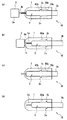
血液は通常、図22(a)に示すようなランセットデバイス34を用いて指先等の部位の皮膚を突き刺して、ごく微量の血液を取り出し、これをセンサ31のキャビティに採取している。
ランセットデバイス34は、図22(b)にその内部構造を示すように、ランセット35がコイルバネ36により弾性的に付勢されている。操作釦37を操作すると、ランセット35のリング状溝35aと、操作釦37と一体となっている係止部材37aとの嵌合が外れ、ばね36による付勢力を解除することにより、ランセット35の針35b先が、略円筒状のケース38の先端から勢い良く飛び出る構造になっている。なおランセット35は、金属性の針35bの部分と、それを保持する樹脂性の保持部35cとからなるが、通常は、衛生面を考慮して、測定のたび毎に、ランセット35を交換するようになっている。
【0007】
また、人や動物から採取した体液を分析するために用いられるバイオセンサは、一般にアルミ包材等で包装された状態やプラスティック容器に収納された状態で保存されており、使用時には、当該アルミ包材等やプラスティック容器からバイオセンサを取り出して使用していた。
【0008】
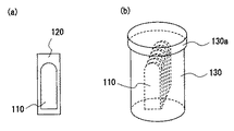
図23(a)は、体液を分析するための試薬層(図示せず)とその分析結果に応じた電気信号を外部に取り出すための電極(図示せず)とを有するバイオセンサ110がアルミ包材120により、密封包装されている状態を示す図であり、略長方形状で一方の短辺側が略半円状となった板状部材からなるバイオセンサ110がこれよりやや大きめの長方形状のアルミ包材120により包装されている。図23(b)は、バイオセンサ110が円筒状で蓋付きのプラスティック容器130内に、略半円状の一端を上側にしてその表面同士が互いに接するように多数配列して密閉収納されている状態を示す図である。
【0009】
そして、測定を行う際には、図23(a)、あるいは図23(b)に示すように保存されたバイオセンサ110を取り出して、図24に示すように、測定装置114のバイオセンサ挿入口114aに対し、バイオセンサ110の略半円状でない短辺を挿入して測定準備を行う。
【0010】
従来のバイオセンサおよびその測定装置は以上のように構成されており、測定を行うに際して、上述のように、患者は、先ず、ランセットデバイス34に新たなランセット35をセットする。そして測定装置32にも新たなセンサ31を装着して、測定準備が整う。その後、ランセットデバイス34を操作して指先等から血液を得て、測定装置32にセットされたセンサ31の先端に、これを点着して測定を行っている。このように患者は、測定のたびごとに、ランセットの交換と、センサの交換をそれぞれ別々に行わなければならず、操作が煩雑であるという問題があった。
【0011】
また、血糖値は1日に何回かモニタする必要があるため、携帯性を考慮してこれらの装置は小型化されている。しかしながら、上記従来の構成では、センサ31、測定装置32、ランセット35、及びランセットデバイス34をそれぞれ一緒に持ち歩かねばならず、全体として嵩張るものとなってしまう。さらにはセンサ31とランセット35とを別々に管理しなければならず、操作や管理が面倒であり、使い勝手の悪いものであった。
【0012】
本発明は上記のような従来のものの課題を解決するためになされたもので、操作や管理をより容易にし、また携帯性もさらに向上させるため、センサとランセットとを一体にしたランセット一体型センサ、及びこれと組み合わされる測定装置を提供することを目的とする。
【0015】
発明の開示
すなわち、上記のような従来の課題を解決するために、本願の請求項1の発明によるランセット一体型センサは、被検体の皮膚を突き刺すことによりその体液を採取するためのランセットと、前記採取した体液の分析を行うためのセンサ本体とが一体となって構成され、前記センサ本体は、前記ランセットが前記センサに対して相対的に移動可能なように、前記ランセットを保持し、前記ランセットは、外部の駆動手段によって駆動されて皮膚を突き刺すことが可能であるとともに、前記外部の駆動手段に接続されていない場合には、前記センサより突出しない位置に係止されるよう構成されたものである。
【0016】
これによれば、センサとランセットとが一体となり、センサとランセットとを別々に管理することなく、一緒に管理することができ、取扱いが容易となる。また、ランセット一体型センサが、測定装置に装着されていない場合に、針先が隠れる位置でランセットが保持されるので、感染などの危険性がなくなり、取扱いも容易となる。
【0017】
また、本願の請求項2の発明によるランセット一体型センサは、請求項1記載のランセット一体型センサにおいて、前記センサ本体は、内部に前記ランセットが貫通可能な空間を有し、該空間内に前記ランセットを保持するようにしたものである。
これによれば、センサの内部にランセットが保持されることとなり、ランセット一体型センサをより小型化する具体的な構造を提供することができる。
【0018】
また、本願の請求項3の発明によるランセット一体型センサは、請求項2記載のランセット一体型センサにおいて、前記センサ本体は、内部に前記ランセットを収納する細長い空間が形成されている、ようにしたものである。
これによれば、細長い空間によってランセットとセンサの位置決めを容易にすることができるようになり、センサとランセットの取り付けや、ランセットの移動空間を確保することができる。
【0019】
また、本願の請求項4の発明によるランセット一体型センサは、請求項1ないし請求項3のいずれかに記載のランセット一体型センサにおいて、前記センサ本体は、薄片状かつ少なくとも一方に凹部を有する2枚のプレートを貼り合わせてなり、互いに貼り合わせた該2枚のプレートの凹部により形成された前記空間内に、前記ランセットを収納する、ようにしたものである。
これによれば、より薄型化したランセット一体型センサを提供することができる。
【0020】
また、本願の請求項5の発明によるランセット一体型センサは、請求項1ないし請求項4のいずれかに記載のランセット一体型センサにおいて、前記ランセットは、皮膚を突き刺し体液を採取する際に、その針先を収納している前記センサ本体の内部より突出する、ようにしたものである。
これによれば、ランセットの針先がセンサ内に収納されるので、より安全性を高めることができる。
【0021】
また、本願の請求項6の発明によるランセット一体型センサは、請求項1ないし請求項5のいずれかに記載のランセット一体型センサにおいて、前記体液を採取するキャビティを、前記センサ本体のランセットを収納する空間とは別に備える、ようにしたものである。
これによれば、体液を採取するキャビティ内をランセットにて損傷させる危険を回避することができる。
【0022】
また、本願の請求項7の発明によるランセット一体型センサは、請求項1ないし請求項5のいずれかに記載のランセット一体型センサにおいて、前記センサ本体のランセットを収納する空間は、前記体液を採取するキャビティを兼ね、該ランセットを収納する空間内に、体液を採取する、ようにしたものである。
これによれば、ランセットが皮膚を突き刺すために移動する空間内に、体液を採取するため、ランセット一体型センサをより小型化することができる。
【0023】
また、本願の請求項8の発明によるランセット一体型センサは、請求項1ないし請求項6のいずれかに記載のランセット一体型センサにおいて、前記ランセットの針先が突出するセンサの先端部側に、体液を採取するキャビティの入口を設けるようにしたものである。
これによれば、針先が突出するセンサの先端部側にて体液がキャビティに収容されるため、採取した体液が外気にさらされる時間を短く抑えられる。
【0024】
また、本願の請求項9の発明によるランセット一体型センサは、請求項1ないし請求項8のいずれかに記載のランセット一体型センサにおいて、前記センサ本体は、キャビティ内に体液の特性結果を出力するための電極を備える、ようにしたものである。
これによれば、体液の特性を電気的に測定することが可能となる。
【0025】
また、本願の請求項10の発明によるランセット一体型センサは、請求項9記載のランセット一体型センサにおいて、体液の特性を電気的に測定するため、外部の測定装置と接続される接続端子を前記キャビティを有するセンサ本体の一端に備える、ようにしたものである。
これによれば、体液の特性を外部の測定装置に接続し、電気的に測定することが可能となる。
【0026】
また、本願の請求項11の発明によるランセット一体型センサは、請求項6ないし請求項10のいずれかに記載のランセット一体型センサにおいて、前記キャビティ内に、採取した体液と反応する試薬を備える、ようにしたものである。
これによれば、体液の特性を、試薬と体液との化学反応により、光学的あるいは電気化学的に測定することが可能となる。
【0027】
また、本願の請求項12の発明によるランセット一体型センサは、請求項1ないし請求項10のいずれかに記載のランセット一体型センサにおいて、前記ランセットは、その針先とは反対側の端部が前記センサ本体より突出しており、該突出した端部が外部の測定装置の駆動手段と係合して駆動され、皮膚の突き刺し動作が行われる、ようにしたものである。
これによれば、ランセットを駆動する外部の駆動手段は、ランセットの基端部を把持して、センサの長手方向にランセットを移動させて、突き刺し動作を行うことができる。
【0028】
また、本願の請求項13の発明によるランセット一体型センサは、請求項12に記載のランセット一体型センサにおいて、前記ランセットの針先と反対側の端部には、前記外部の測定装置の駆動手段と嵌合するコネクタが設られ、該コネクタが前記駆動手段と嵌合して、皮膚の突き刺し動作が行われる、ようにしたものである。
これによれば、ランセットを駆動するための外部の駆動手段が、ランセットの端部をより把持し易くなり、より確実にランセットを駆動することができる。
【0029】
また、本願の請求項14の発明によるランセット一体型センサは、請求項13に記載のランセット一体型センサにおいて、前記コネクタは樹脂により形成され、前記ランセットに比べ大径な形状を有する、ようにしたものである。
これによれば、ランセットを駆動するための外部の駆動手段が、ランセットの端部をより把持し易くなり、さらに確実にランセットを駆動することができる。
【0030】
また、本願の請求項15の発明によるランセット一体型センサは、請求項1ないし請求項14のいずれかに記載のランセット一体型センサにおいて、前記ランセットの針先には取り外し可能な保護カバーが取り付けられ、該保護カバーはランセットの突き刺し動作時には取り除かれる、ようにしたものである。
これにより、ランセットの針先によるけがや、針先の汚染を防止することができる。
【0031】
また、本願の請求項16の発明によるランセット一体型センサは、請求項15に記載のランセット一体型センサにおいて、前記保護カバーは、内部に前記針先を収容する筒状部と、該筒状部の前記針先の先端側に、前記ランセットからの取り外しを容易にする幅広の把持部とを有する、ようにしたものである。
これにより、ランセットの針先を覆う保護カバーの取り外しが容易となる。
【0032】
また、本願の請求項17の発明によるランセット一体型センサは、請求項15に記載のランセット一体型センサにおいて、前記ランセットと前記駆動手段との係合および該ランセットと一体となるセンサ本体の前記測定装置への装着は、前記保護カバーの把持部を掴みながら行う、ようにしたものである。
これにより、センサやランセットを掴むことなく、保護カバーを把持することで、センサおよびランセットを測定装置に装着することができる。
【0033】
また、本願の請求項18の発明によるランセット一体型センサは、請求項16に記載のランセット一体型センサにおいて、前記筒状部は、その内部に前記センサ本体の先端部を収納可能な空間が形成されている、ようにしたものである。
【0034】
これにより、外部の測定装置にセットされている、測定が終了したセンサに対して、その先端が保護カバー内に収納されるようにセットすることができる。そしてこの状態で、使用済みのセンサを測定装置から取り外すことができ、衛生的に処理することができる。
【0035】
また、本願の請求項19の発明によるランセット一体型センサは、請求項1ないし請求項18のいずれかに記載のランセット一体型センサにおいて、該ランセット一体型センサは、前記センサ本体と前記ランセットの周囲を覆い該センサ本体およびランセットを保持するホルダーを備える、ようにしたものである。
これにより、センサとランセットの外周をホルダーで一体的に覆っており、このホルダーを把持することにより、ランセット一体型センサを容易に取り扱うことができる。
【0036】
また、本願の請求項20の発明によるランセット一体型センサは、請求項19記載のランセット一体型センサにおいて、前記ホルダーを透明な材料により形成するようにしたものである。
これにより、ホルダー内のセンサやランセットを容易に確認することができ、更に取扱いが容易となる。
【0037】
また、本願の請求項21の発明によるランセット一体型センサは、請求項1ないし請求項20のいずれかに記載のランセット一体型センサにおいて、該ランセット一体型センサは、体液の採取およびその分析を一回行った後に廃棄する、使い捨てタイプである、ようにしたものである。
これにより、測定のたび毎に、センサだけでなく、ランセットも必ず新たなものとなるので、衛生的に管理することができる。
【0038】
また、本願の請求項22の発明による測定装置は、請求項1ないし21のいずれかに記載のランセット一体型センサが着脱自在に取り付けられ、該ランセット一体型センサが採取した体液の特性を測定するための測定装置であって、前記ランセット一体型センサが該測定装置に装着された後に、前記ランセットを駆動して、皮膚を突き刺すためのランセット駆動手段を備える、ようにしたものである。
【0039】
これにより、測定装置に従来のランセットデバイスを一体化することとなり、従来のように別途ランセットデバイスが必要となるのではなく、測定装置のみで、穿刺の操作と測定とを行うことができることとなる。またこの測定装置には、センサと一体となったランセットが測定のたびごとに装着されるので、従来の測定装置には、ランセットの駆動手段を付加するのみでよく、低コストで実現することができる。
【0040】
また、本願の請求項23の発明による測定装置は、請求項22に記載の測定装置において、前記ランセット一体型センサは、前記測定装置への装着が完了した時点で、少なくともその一端が該測定装置より露出している、ようにしたものである。
【0041】
これにより、患者は、露出したランセット一体型センサの一端を目印に、ランセットによる指先等の穿刺や、センサへの点着等を行うものであり、操作が容易となる。またランセット一体型センサの一端が露出しているため、測定装置が体液等により汚染されることを防止することもできる。
【0042】
また、本願の請求項24の発明による測定装置は、請求項22または請求項23に記載の測定装置において、前記ランセット駆動手段は、体液を採取するため皮膚を突き刺す時のみ、センサよりその針先が突出し、それ以外は、前記針先がセンサの内部に収納されるように、前記ランセット一体型センサのランセットを駆動する、ようにしたものである。
これにより、ランセットの針先がセンサ内に収納されるので、より安全性を高めることができる。
【0043】
また、本願の請求項25の発明による測定装置は、請求項24に記載の測定装置において、該測定装置は、前記ランセット一体型センサのセンサ本体の一端に設けられた電極端子との電気的接続を保つためのコネクタを備え、採取した体液の特性を内部の電気回路にて測定し得るように構成する、ようにしたものである。
これにより、体液の特性を電気的に測定することが可能となる。
【0044】
また、本願の請求項26の発明による測定装置は、請求項15ないし請求項17のいずれかに記載のランセット一体型センサが装着される、請求項22ないし請求項25のいずれかに記載の測定装置において、前記ランセット駆動手段は、ランセットの針先とは反対側の端部と係合するか、あるいは前記保護カバーの把持部を把持することにより、前記ランセットの駆動を行う、ようにしたものである。
【0045】
これにより、ランセットを駆動する外部の駆動手段は、ランセットの端部を把持して、センサの長手方向にランセットを移動させて、突き刺し動作をおこなうこととなる。また端部に保持部を設けることにより、駆動手段がより把持し易くなる。
【0046】
また、本願の請求項27の発明による測定装置は、請求項26に記載の測定装置において、前記ランセット駆動手段は、ランセットをセンサの長手方向に付勢するバネを有しており、測定装置本体に設けた押し釦により、前記バネの付勢力を解除して、ランセットを突き出すようにしたものである。
これにより、バネの端部に、ランセットの端部あるいは保持部が係合し、コイルバネの弾性力がランセットに付勢される。
【0047】
また、本願の請求項28の発明による測定装置は、請求項22ないし請求項27のいずれかに記載の測定装置において、請求項15ないし請求項18のいずれかに記載されたランセット一体型センサが着脱可能に取り付けられ、ランセットの先端に保護カバーを被せた状態で、ランセット一体型センサの測定装置への装着が行われ、センサが該測定装置のコネクタに保持され、ランセットの針先とは反対側の端部が前記ランセット駆動手段に把持されるように構成したものである。
これにより、ランセットの針先によるけがや、針先の汚染を防止することができる。
【0048】
また、本願の請求項29の発明による測定装置は、請求項22ないし請求項28のいずれかに記載の測定装置において、請求項19または請求項20に記載されたランセット一体型センサが着脱可能に取り付けられ、センサとランセットとは、ホルダーに保持されたままの状態で、測定装置への装着が行われるように、ホルダーを測定装置へ係合させる動作に合わせて、センサがコネクタに保持され、ランセットの針先とは反対側の端部あるいは前記保護カバーの把持部が前記駆動手段に把持されるように構成したものである。
これにより、センサとランセットの外周をホルダーで一体的に覆っており、このホルダーを把持することにより、ランセット一体型センサを容易に取り扱うことができる。
【0049】
また、本願の請求項30の発明による測定装置は、請求項22ないし請求項29のいずれかに記載の測定装置において、使用済みのランセット一体型センサは、測定装置本体に設けた操作釦の操作により、手で触れることなく、測定装置本体から取り外されるように構成したものである。
これにより、使用済みのランセット一体型センサを手で触れることなく、測定装置より取り外すことができるので、手を汚すこともなく、感染症等を防ぐことができる。
【0050】
また、本願の請求項31の発明による測定装置は、請求項22ないし請求項30のいずれかに記載の測定装置において、ランセットの針先の、センサの先端からの突出量を、測定装置本体に設けた表示手段に表示できるように構成したものである。
これにより、ランセットの針先の突出量を、表示手段でよりはっきりと確認することができ、より使いやすいものとなる。
【0051】
また、本願の請求項32の発明によるランセット一体型センサは、針部を有し、皮膚を穿刺して体液を採取するランセットと、採取された体液を分析するためのセンサとが一体として構成されたランセット一体型センサにおいて、該センサには、内部に前記ランセットの一部を摺動可能に収容する空隙が形成され、前記ランセットに対し、前記皮膚を穿刺する方向とは反対方向に力を印加して前記センサ内に前記針部を収納することにより、前記ランセットと前記センサとが相互にロックされる、ようにしたものである。
これにより、体液の付着したランセットがセンサ内でロックされ、その針先部に誤って手が触れることがなく、測定装置から安全に取り外しを行うことが可能となる。
【0052】
また、本願の請求項33の発明によるランセット一体型センサは、請求項32記載のランセット一体型センサにおいて、前記ランセットは略長方形状の板状部材からなり、前記ランセットの針部は前記板状部材の一方の短辺側の中央付近に該板状部材の長手方向に沿って突出するように配設され、前記空隙は前記ランセットをその長手方向に沿って所定量スライドさせた際の輪郭形状と略同一の形状に形成され、前記センサの先端および後端に、それぞれ前記針部および前記ランセットの他方の短辺を該センサの外部に突出させる開口が形成されている、ようにしたものである。
これにより、体液の付着したランセットがセンサ内でロックされ、その針先部に誤って手が触れることがなく、測定装置から安全に取り外しを行うことが可能となる。
【0053】
また、本願の請求項34の発明によるランセット一体型センサは、請求項32または請求項33に記載のランセット一体型センサにおいて、前記ランセットにはロック用凸部,ロック用凹部の何れか一方が、前記センサには前記ロック用凸部,ロック用凹部の何れか一方と嵌合するロック用凹部,ロック用凸部の何れか一方が、それぞれ形成され、前記ランセットとセンサとのロックは、前記ロック用凸部と前記ロック用凹部とが嵌合することにより行われる、ようにしたものである。
これにより、体液の付着したランセットがセンサ内でロックされ、その針先部に誤って手が触れることがなく、測定装置から安全に取り外しを行うことが可能となる。
【0054】
また、本願の請求項35の発明によるランセット一体型センサは、請求項34記載のランセット一体型センサにおいて、前記ランセットはその2つの長辺から幅方向に突出する2つの平板状の突起部が形成され、該突起部はその上面に前記ロック用凹部が形成され、前記センサの内部に形成された、前記ランセットを摺動可能に収容する空隙は、その幅方向に突出し前記ランセットの前記2つの突起部を収容する2つの窪み部を有し、該窪み部はその天井面に前記ロック用凸部が形成されている、ようにしたものである。
これにより、体液の付着したランセットがセンサ内でロックされ、その針先部に誤って手が触れることがなく、測定装置から安全に取り外しを行うことが可能となる。
【0055】
また、本願の請求項36の発明によるランセット一体型センサ用測定装置は、請求項33記載のランセット一体型センサを用いて測定を行う測定装置であって、前記測定装置の一側面の開口から挿入された前記ランセット一体型センサを該測定装置内部で案内しその進行方向を規制する案内部材と、前記測定装置内でバネ部材により前記ランセット一体型センサの挿入方向とは反対方向に押圧付勢され、前記案内部材によって該測定装置の内部に向けて案内されてきた前記ランセットの他方の短辺と嵌合し該ランセットを前記開口に向けて押圧付勢するランセット付勢部材と、前記ランセット一体型センサが前記測定装置のより内部側に挿入された時前記ランセット付勢部材を該測定装置内の所定位置で固定するロック部材と、手動操作により前記ロック部材による前記ランセット付勢部材の固定を解除するロック解除用部材と、前記ランセット付勢部材および前記案内部材の間に設けられ、手動操作により、前記ランセット一体型センサの前記センサを前記開口側に向けて押圧付勢するための排出用部材とを備えるようにしたものである。
【0056】
これにより、体液の付着したランセットがセンサ内でロックされ、その針先部に誤って手が触れることがなく、測定装置から安全に取り外しを行うことが可能なランセット一体型センサを装着して測定が可能となり、測定後は針先部をセンサ内に収容して安全に取り外すことが可能な測定装置が実現できる。
【0057】
また、本願の請求項37の発明によるランセット一体型センサ用測定装置は、請求項36記載のランセット一体型センサ用測定装置において、前記排出用部材は、前記測定装置の主面上に露出した操作レバーを前記開口側に向けてスライド操作することにより、該操作レバーと一体の押圧部材が前記ランセット一体型センサの前記皮膚を穿刺する側とは反対側の端部の両側辺近傍を押圧し、該ランセット一体型センサを排出する、ようにしたものである。
【0058】
これにより、体液の付着したランセットがセンサ内でロックされ、その針先部に誤って手が触れることがなく、測定装置から安全に取り外しを行うことが可能なランセット一体型センサを装着して測定が可能となり、測定後は針先部をセンサ内に収容して安全に取り外すことが可能な測定装置が実現できる。
【0059】
また、本願の請求項38の発明によるランセット一体型センサ用測定装置は、請求項1ないし請求項21のいずれかに記載のランセット一体型センサ用測定装置であって、該ランセット一体型センサ用測定装置は、その一側面に開口が設けられ、前記ランセット一体型センサ用測定装置は、前記開口に対応して設けられ内部に前記ランセット一体型センサを収容可能な空隙を有し、前記開口を有する一側面には、内部を前記ランセット一体型センサが通過可能な筒状のホルダー体を、前記ランセット一体型センサ用測定装置に対し着脱自在に装着するホルダー装着部が形成され、前記ホルダー体は、前記ランセット一体型センサ用測定装置を前記空隙内に収容する際に、該ランセット一体型センサを案内し、収容後は前記ランセット一体型センサの上記皮膚を穿刺する側の一端の近傍部分を保持する、ようにしたものである。
【0060】
これにより、ホルダー体を測定装置から取り外すことができる構造とすることで、交換や洗浄が容易にでき、個人専用機としてのみならず、他の人でも使用でき、ランセット一体型センサ用測定装置を安全かつ衛生的に使用することができる。
【0061】
また、本願の請求項39の発明によるランセット一体型センサ用測定装置は、請求項38に記載のランセット一体型センサ用測定装置において、前記ホルダーと、前記ホルダー装着部との、相互の嵌合部は、上下方向、或は左右方向において非対称な形状を有し、前記ホルダー装着部に対する前記ホルダーの上下の向きが或る方向である場合のみ、前記ホルダー装着部に対する前記ホルダーの装着が可能となる、ようにしたものである。
これにより、常にホルダー体を正常な方向で測定装置に装着することができ、ランセット一体型センサを測定装置に逆挿入することを防止することができる。
【0062】
また、本願の請求項40の発明によるランセット一体型センサ用測定装置は、請求項38に記載のランセット一体型センサ用測定装置において、前記ホルダー体が装着される前記ホルダー装着部の開口は、角部に相当する部分が丸められた横長の略長方形状を有し、縦方向の2辺の中央付近には幅方向に張り出した小開口をそれぞれ有する、ようにしたものである。
これにより、ホルダー装着部の開口が縦方向と幅方向とで非対称となり、ホルダーの装着方向の間違いがなくなる。
【0063】
また、本願の請求項41の発明によるランセット一体型センサ用測定装置は、請求項40に記載のランセット一体型センサ用測定装置において、前記ホルダー体は、ヒンジ形状のストッパーを有し、該ヒンジ形状のストッパーの内側辺が前記ホルダー体に固定され、前記ヒンジ形状のストッパーの外側辺が前記ホルダー装着部の嵌合部と嵌合停止する、ようにしたものである。
これにより、常にホルダー体を正常な方向で測定装置に装着することができ、ランセット一体型センサを測定装置に逆挿入することを防止することができる。
【0064】
また、本願の請求項42の発明によるランセット一体型センサ用測定装置は、請求項40に記載のランセット一体型センサ用測定装置において、前記ホルダー体は、前記測定装置の一側面に装着される側の、前記小開口を除く前記開口の周縁部に該開口面に沿って延在する周側縁部を有し、該周側縁部の前記小開口に対応する部分には、前記ヒンジ形状のストッパーが設けられ、該ヒンジ形状のストッパーは、帯状の弾性部材を前記ホルダー体へのランセット一体型センサの嵌入方向に沿って延在させ該弾性部材を途中でほぼ180度外側に向けて折り曲げてなる、ようにしたものである。
これにより、ストッパーの弾性による広がり力により、ホルダー体が測定装置に安定に装着される。
【0065】
また、本願の請求項43の発明によるランセット一体型センサ用測定装置は、請求項42に記載のランセット一体型センサ用測定装置において、前記ヒンジ形状のストッパーは、前記帯状の弾性部材の先端部に該弾性部材より厚みを有し、前記ホルダー体を前記開口に係止させた際の位置決めを行うクリップ部材を有する、ようにしたものである。
これにより、ストッパーの先端側が測定装置の小開口の内側に係止されるため、ストッパーが小開口から外れることがなくなり、ホルダー体が安定に装着できる。
【0074】
また、本願の請求項44の発明に係るバイオセンサ用カートリッジは、請求項1〜21、32〜35のいずれかに記載のランセット一体型バイオセンサを複数収納するバイオセンサ用カートリッジにおいて、上記カートリッジ本体はその上面の一端に、当該カートリッジ本体の上面を覆う蓋部を回動自在に軸止する蝶番部が設けられ、上記カートリッジ本体は、各ランセット一体型バイオセンサをそれぞれ直立して支持する溝部を、複数有し、上記複数の溝部は、上記バイオセンサを挿入して測定を行う測定装置の挿入口を、隣接するランセット一体型バイオセンサに接触することなく差し込むことができる間隔で、上記カートリッジ本体の上面から下面に向けて、互いに平行に形成されている、ものとしたものである。
【0075】
これにより、蓋部を開け、ランセット一体型センサに測定装置のセンサ挿入口部を押し込むだけで装着できるので、測定ごとにランセット一体型センサを手に取り、測定装置に挿入するという面倒な測定準備が省け、使い勝手を良くすることができる。
【0076】
また、本願の請求項45の発明に係るバイオセンサ用カートリッジは、請求項44記載のバイオセンサ用カートリッジにおいて、上記ランセット一体型バイオセンサは、未使用状態において該ランセット一体型バイオセンサより突出しているランセットを保護する略正方形かつ幅狭のプロテクターと、内部に上記ランセットを滑動自在に収容する略長方形状かつ先頭側が半円状で上記プロテクターより幅広のセンサ本体と、上記ランセットに設けられ上記センサ本体より後方に突出し、上記センサ本体と同程度の幅を有するコネクタ部とを有し、上記複数の溝部はそれぞれ、上記カートリッジ本体の最も下面側に設けられ、上記プロテクターの形状に合致した、幅狭の第1の溝と、該第1の溝より上側に設けられ、上記センサ本体の一部の形状に合致した、上記第1の溝より幅広の第2の溝と、該第2の溝より上側に設けられ、上記センサ本体が挿入される上記測定装置の挿入口部の形状に合致した、上記第2の溝より幅広の第3の溝とからなる、ようにしたものである。
【0077】
これにより、複雑な形状を持つランセット一体型センサを互いに間隔をあけて支持でき、ランセット一体型センサに測定装置のセンサ挿入口部を押し込むだけで装着できるため、測定ごとにランセット一体型センサを手に取り、測定装置に挿入するという面倒な測定準備が省け、使い勝手を良くすることができる。
【0078】
また、本発明の請求項46記載のバイオセンサ用カートリッジは、請求項45記載のバイオセンサ用カートリッジにおいて、上記挿入口部は、測定装置に一側面より突出する柱状突起内を貫通する空隙に上記センサ本体を収容し、上記測定装置内に延在する上記空隙内に上記コネクタ部が収容される、ようにしたものである。
【0079】
これにより、複雑な後端形状を持つランセット一体型センサに測定装置のセンサ挿入口部を押し込むだけで装着でき、測定ごとにランセット一体型センサを手に取り、測定装置に挿入するという面倒な測定準備が省け、使い勝手を良くすることができる。
【0080】
また、本発明の請求項47に記載のランセット一体型センサ用測定装置は、請求項1ないし請求項21のいずれかに記載のランセット一体型センサを装着して測定を行うランセット一体型センサ用測定装置であって、前記ランセットを、その待機位置より、前記センサの長手方向に沿って、該ランセットが上記皮膚を穿刺する方向に駆動させる駆動手段が設けられ、前記駆動手段は、上記ランセットが上記皮膚を穿刺する方向に、前記ランセットを駆動させた後、該ランセット一体型センサを該ランセット一体型センサ用測定装置に装着した状態のままで、前記ランセットを上記待機位置に復帰駆動させることが可能である、ようにしたものである。
【0081】
これにより、体液を採取する際に、皮膚を突き刺せなかったり、なんらかの不具合で測定ができなかった場合であっても、再度の測定準備を容易に行うことができ、ランセット一体型センサ用測定装置の使い勝手をより良くすることができる。
【0082】
また、本発明の請求項48に記載のランセット一体型センサ用測定装置は、請求項47に記載のランセット一体型センサ用測定装置において、前記駆動手段は、その上記皮膚を穿刺する側の一端に、上記ランセットの上記皮膚を穿刺する側と反対側を受けるコネクタ受けが取り付けられたシャフトを有し、該シャフトの上記皮膚を穿刺する側と反対側の一端に、上記ランセットを上記皮膚を穿刺する方向と反対の方向に復帰駆動させるためのプルスティックが設けられ、上記コネクタ受けには、該駆動手段の動作を開始するための操作ボタンの押圧により、そのロックが解除される、上記シャフトに装着されたばねにより上記コネクタ受けが上記皮膚を穿刺する方向に移動しようとする付勢力に対し、該コネクタ受けの移動を停止する爪部が設けられている、ようにしたものである。
【0083】
これにより、体液を採取する際に、皮膚を突き刺せなかったり、なんらかの不具合で測定ができなかった場合であっても、プルスティックを操作することにより再度の測定準備を容易に行うことができるので、ランセット一体型センサ用測定装置の使い勝手をより良くすることができる。
【0084】
また、本発明の請求項49に記載のランセット一体型センサ用測定装置は、請求項48に記載のランセット一体型センサ用測定装置において、該測定装置はその内部の空間に、前記シャフトをその中央付近で摺動自在に支持する支持部材を有し、前記ばねは、コイルばねであり、前記シャフトの前記支持部材と前記コネクタ受けとの間に装着されている、ようにしたものである。
これにより、シャフトが測定装置内部で支持され、コイルばねが支持部材と前記コネクタ受けとの間に装着されランセットの駆動力を供給することができる。
【0085】
また、本発明の請求項50に記載のランセット一体型センサ用測定装置は、請求項48に記載のランセット一体型センサ用測定装置において、前記プルスティックは、上記皮膚を穿刺する側の端部に開口が形成され、前記シャフトは、上記皮膚を穿刺する側と反対側が前記開口を介して前記プルスティック内に出没自在に収容され、前記シャフトの上記皮膚を穿刺する側と反対側の端部は、該端部が前記プルスティック内より上記皮膚を穿刺する側に抜け出すのを防止する抜け出し防止部材を有する、ようにしたものである。
これにより、プルスティックを引っ張ることでシャフトがランセットの突出方向と逆方向に引き出すことが可能となる。
【0086】
また、本願の請求項51に記載のランセット一体型センサ用測定装置は、請求項48に記載のランセット一体型センサ用測定装置において、前記駆動手段は、該ランセット一体型センサ用測定装置と上記プルスティックとの間に設けられ、前記ランセットの皮膚を穿刺する針部の突出量を調節するランセット突出量調節器を備える、ようにしたものである。
これにより、ランセットの針先の突出量を調整でき、測定者の体液の滲出の具合を調整したり、ランセットの穿刺による痛みを軽減することができる。
【0087】
また、本願の請求項52に記載のランセット一体型センサ用測定装置は、請求項51に記載のランセット一体型センサ用測定装置において、前記プルスティックは、略円筒形状を有し、上記皮膚を穿刺する側と反対側の端部側には一部が当該円筒状部よりも大径となったつまみ部が形成されており、前記ランセット突出量調節器は、略円筒状の形状を有し、上記皮膚を穿刺する側と反対側の端部に前記プルスティックの前記円筒状部と同径の開口が形成され、該開口を介して前記円筒状部を摺動自在に収容し、本ランセット一体型センサ用測定装置の前記ランセットの上記皮膚を穿刺する側と反対側の一側面に該測定装置の内部に向けて形成されたねじ穴と螺合し、該螺合方向あるいはその逆方向に回転することにより、前記ランセットの突出量を調節する、ようにしたものである。
これにより、ランセットの針先の突出量を調整できるので、測定者の体液の滲出の具合を調整したり、ランセットの穿刺による痛みを軽減することができる。
【0088】
発明を実施するための最良の形態
(実施の形態1)
以下、本発明の一実施の形態について、電気化学的に血糖値を測定する血糖値センサを例に挙げ、図面を参照しながら具体的に説明する。
【0089】
この実施の形態1は、ランセットとセンサとを一体化することによりその管理や持ち運びを容易にしたランセット一体型センサおよびこのランセット一体型センサの駆動および測定を行うランセット一体型センサ用測定装置に関するものであり、請求項1ないし請求項31の発明に対応するものである。
【0090】
すなわち、この実施の形態1によるランセット一体型センサは、細長い小片状のセンサとランセットを一体にしたものであり、より具体的には、センサの長手方向に沿って、ランセットが平行に移動するような一体構造としたものである。
【0091】
そしてこのランセット一体型センサが装着される測定装置には、従来のランセットデバイスのランセット駆動機能を付加している。すなわち、装着されたランセット一体型センサのうちのランセットを駆動するための駆動手段をも備えたものとしている。
【0092】
この構成においては、測定のたび毎に、新たなランセット一体型センサを測定装置にセットする。そして測定装置を把持し、その駆動手段を動作させてランセットで指先を穿刺する。それに引き続いて、今度はセンサに血液を点着する動作で血糖値等の測定を行うことができる。
以下では、これらランセット一体型センサおよび測定装置について詳述する。
【0093】
図1は、本発明の実施の形態1におけるランセット一体型センサの斜視図及び分解斜視図を示している。図1(a)において、10はランセット一体型センサを示しており、そのうち1は細長い小片状のセンサを、2はその大部分がセンサ1の内部の空隙(空間)1aに収容され、センサ(センサ本体)1に対して、その長手方向にスライド可能なように支持されているランセットを示している。
【0094】
3はランセット2の針先を保護すべく、針先に圧入されている保護カバーであり、測定時には除去される。4は後で詳述する測定装置に対して電気的に接続を行うための電極端子である。5は、センサ1の半円形状の先端部に設けられたキャビティである。
【0095】
センサ1の構造は、図1(b)に示すように、ポリエチレンテレフタレートなどの樹脂よりなる、カバー(プレート)6と基板(プレート)7とを貼り合わせてなる。またランセット2は、金属製の針2aと、針2aがその先端側に設けられこれを保持するためのコネクタ(端部)2bとからなり、この略短冊状のコネクタ2bは、後述する測定装置の駆動手段と嵌合するよう、センサ1の後端よりその後端側が突出している。
【0096】
カバー6の下面には、ランセット2の形状に沿った凹部が設けられている。すなわち、コネクタ2bをその長手方向にスライドできるように収納するようにその外形に沿った溝(凹部)6aと、針2aの部分が収納される細長い溝(凹部)6bとが形成されている。針2aが収納される溝6bは、センサ1の先端まで通じている。また基板7はその表面に、電極端子4に通じる一対の電極8が形成され、さらにその表面には、図示しない試薬層が形成されている。
【0097】
このようにランセット一体型センサは、ランセット2を介在させた状態で、カバー6と基板7を貼り合わせてなる。したがってキャビティ5は、上述の針2aが収納される細長い溝6bの部分を兼ねている。そしてキャビティ5に面して電極8および試薬層の一部が露出している。
このように、ランセット2は、センサ1の長手方向に沿って移動可能になっており、その動きを図2の平面図にて説明する。
【0098】
図2(a)は、ランセット2がセンサ1に対して、最も先端側に位置する状態を示している。すなわち、コネクタ2bに対しその主面と同一平面内でコネクタ2bの長辺と直交する方向に突出するように形成した微小突起2cが、カバー6に形成した幅広の凹溝(凹部)60aの、センサ1の最も先端側の端部の壁面60bに当接している。この状態では、ランセット2の針2aがセンサ1の先端より、最も長く突出することとなる。また図2(b)は、コネクタ2bの微小突起2cが、凹溝60aの、センサ1の最も後端側の端部の壁面60cに当接する状態を示している。この状態では、ランセット2の針先はすっかりセンサ1内に収納されている。
【0099】
ここで凹溝60aの形状は、図2(a)及び図2(b)に示すように、微小突起2cが位置する端部において、その幅は、微小突起2cを含めたコネクタ2bの幅よりも若干狭くなるよう湾曲している。よって凹溝60aの端部において、互いの押圧力や摩擦力によってコネクタ2bがセンサ1に係止されるようになっている。
【0100】
以上がランセット一体型センサの構成であり、測定に際しては保護カバー3が取り除かれ、図2(c)に示すようにランセット2の針2a先がキャビティ5の開口より突出した状態で、指先等の穿刺が行われる。そして血液を点着しキャビティ5内に血液を吸引し血糖値を測定する際には、図2(d)に示すように、ランセット2の針先は、キャビティ5内に吸引した血液に接触しないよう、キャビティ5を回避した溝6a内に位置する。
【0101】
測定装置
次に上述のランセット一体型センサに組み合わされる測定装置の一例について、図面を参照しながら説明する。
図3は、ランセット一体型センサが装着された状態の測定装置11について、その斜視図を示しており、図3(a)は主にその上面側を、図3(b)は主にその下面側を示している。12は、測定結果等を表示するディスプレイ(表示手段)、13はランセット一体型センサを受け入れる装着口である。14は、指先等を穿刺するよう、測定装置11に装着されたランセットを勢い良く突出するように駆動するための押しボタン(ロック解除用部材)である。また15は、測定装置11から使用済みのランセット一体型センサを排出するためのスライドボタン(排出用部材,操作ボタン)である。また、16は、ランセットの針先の突出量を調整する調整ボタン(ランセット突出量調節器)である。
【0102】
図4(a)は、測定装置11の内部構造を示すべく、外装ケースの上側を取り除いた状態での斜視図を示しており、センサと電気的に接続される接続端子、およびランセットのコネクタと係合する駆動手段の部分を具体的に示している。また、図4(b)は、測定装置の側面図を示している。
【0103】
17はセンサの電極端子との電気的接続を図る接続端子を備えるガイドである。一対のガイド17は、樹脂成形により外装ケースの底面上の基板11aより断面が略L字型に植設されており、接続端子がその天井面に形成されている。また各ガイド17のコネクタ受け19に対向する終端面には終端部材17aが植設されてガイド17同士の間を除いて行き止まりとなっている。ランセット一体型センサを装着する際には、このガイド17によりセンサ10が案内されてセットされる。
【0104】
18は、ランセット2を駆動するコイルバネ(ランセット付勢部材)であり、19はランセット2のコネクタ2bと嵌合するコネクタ受け(ランセット付勢部材)である。コネクタ受け19は基板11aに植設された逆L字状の一対の約L字状支持部材24により摺動可能に支持されており、そのセンサ10と嵌合する側面と反対側の側面にはコイルバネ18の一端が固定されている。また、コイルバネ18の他端はバネストッパー(ランセット付勢部材)23により支持されている。ランセット2がコネクタ受け19に係合して、さらに測定装置11内部にランセット2が押し込まれることにより、コイルバネ18が圧縮され、ランセット2を駆動するための駆動力が与えられる。
【0105】
20は押しボタン14より手前のテーパ状突起11cとそのテーパ状突起20aが係合する駆動レバーであり、ランセット2が所定の位置までセットされたときに、この駆動力を保持すべくコネクタ受け19を係止する。そして押しボタン14の押圧動作により係止が解除され、ばね18の押圧付勢力によりランセット2を駆動する。
【0106】
21は、コネクタ受け19の位置を規制するトーションバネであり、センサ10の挿入経路と平行な側面付近に植設された軸止部材25により軸止されている。トーションバネ21は、駆動レバー20により係止されていないコネクタ受け19に対して、コイルバネ18の弾性力に抗する方向に押圧している。トーションバネ21は、ランセット2の針先がキャビティ5内に吸引した血液に接触しないよう、回避したところに位置するように、コイルバネ18の弾性力と釣り合って、コネクタ受け19の位置を規制している。
22はスライドボタン15と一体化されている排出レバーであり、スライドボタン15を矢印aの方向に操作することにより、センサ1の後端を押圧し、これを排出する。
【0107】
測定動作
以上の様に構成したランセット一体型センサ及び測定装置について、一連の測定動作について以下説明をする。
まず、ランセット一体型センサを測定装置に装着する動作から説明する。ランセット一体型センサは、未使用の状態では、図2(a)に示す状態である。すなわち、ランセット2は、その針先がセンサ1より突出する位置にあって、保護カバー3が被せられている。患者は、この保護カバー3の面積の大きな把持部3aを把持しながら、測定装置11の装着口13よりランセット2をコネクタ2b側から挿入していく。
【0108】
保護カバー3の把持部3aをさらに押して、センサ1及びランセット2を押し込むことにより、まず、図5(a)に示すように、センサ1がガイド17により案内されてケース11b内部に進入し、さらに進入を続けることで、その半円状の短辺とは反対側の短辺がガイド17の終端部材17aに当接しケース11b内部への進入が規制される固定位置にセットされ、センサ1の電極端子4が図示しない測定装置11の接続端子に接続される。なお、この図5(a)では、図を見やすくするために、ランセット一体型センサについては、センサ1のみを図示しており、ランセット2の部分は省略している。
【0109】
この時点でセンサ1はその進入を停止しているが、図5(c)に示すように、ランセット2はガイド17の端面部材17aにより動きが規制されないため、ランセット2はさらにケース11bの内側に進めていくことが可能である。すなわち、保護カバー3の押圧力により、図2(a)に示す位置での微小突起2cと凹溝60aとの係合が外れる。そして図2(b)の位置関係で示すように、保護カバー3は、その針2aを保護するチューブ3bの部分がセンサ1内に押し込まれ、保護カバー3の把持部3aの一側面がセンサ1の先端に当接する。
【0110】
そして患者が図5(a)の状態よりさらに奥に保護カバー3を押し込むと、今度は、ランセット2のコネクタ2bがコネクタ受け19の凹部19aに嵌合し、図5(b)に示すように、コイルバネ18が圧縮され、コネクタ受け19の駆動レバー20のテーパ状突起20aが押しボタン14の手前のテーパ状突起11cにより係止され、センサ10の装着が完了する。
【0111】
次に、採血動作と血液の点着動作について説明する。ランセット一体型センサの装着動作が完了すれば、図3(a)に示す状態となる。患者は、測定装置11を持ち、採血しようとする体の部位、例えば指先等にセンサ10の先端を軽く押し当てる。
【0112】
そこで押しボタン14を押すと、ランセット2が駆動されて、センサ10の先端よりその針先が勢いよく突出し、皮膚を穿刺する。このときセンサからの針先の突出量は、調整ボタン16を横方向にスライドすることにより可変することが可能である。これは、調整ボタン16を横方向にスライドすることにより、トーションバネ21を測定装置11内部で横方向に移動させ、そのバネ力を調整する、あるいは、調整ボタン16の横方向の動きを、バネストッパー23をランセット2の駆動方向に沿って前後に移動させる動きに変換する機構(図示せず)が駆動されることにより、押しボタン14と係止したコネクタ受け19とバネストッパー23との距離を増減する、等で可能であり、その突出量については、調整ボタン16のスライド量を測定装置のCPU等により換算することでディスプレイ12に表示させることも可能である。
【0113】
患者は穿刺された指先から滲み出す微量の血液を、センサ10の先端に点着し、毛管現象を利用してキャビティ5内に血液を吸引させる。測定装置11は内部の電子回路にて、血糖値の測定を行い、ディスプレイ12に結果を表示する。測定結果が表示され、測定が終了すれば、スライドボタン15をランセット2が突出する方向に操作することで、ランセット一体型センサを測定装置11外へ排出でき、ランセット一体型センサは使い捨てにする。
【0114】
このとき排出レバー22がセンサ1をその後端から押圧していくが、その時点では、ランセット2は、そのコネクタ2bが測定装置11のコネクタ受け19に係合したままである。センサ1が先に排出されることに伴い、センサ1とランセット2との位置関係は、図2(d)に示す状態となる。そしてランセット2の微小突起2cは凹溝60aに係止した状態となり、ランセット2の針先がセンサ1より突出しなくなった状態で、測定装置11外へ排出されることになる。このため針先がセンサ外部に露出していることによる怪我や感染を防止することができる。
【0115】
このように、本実施の形態1によるランセット一体型センサによれば、センサとランセットとが一体化されるためその管理が容易となり、使用の都度これらを別々に交換する手間が省け、測定装置にセンサとランセットとを同時にセットできるため、装着が容易となり、携帯の際にかさばることがなくなる。
【0116】
なお、ランセット一体型センサを排出するときには、怪我や感染をより確実に防止するため、図6(a)に示すように、保護カバー3の把持部3aの一側面に、センサ1の先端形状に沿った半円形の空間を形成しておき、これを同図(b)に示すように、センサ1に被せた上で排出するようにも構成できる。
【0117】
また、本実施の形態1によるランセット一体型センサは、ランセットの先端に保護カバーを被せた形状をしているが、このランセット一体型センサおよび保護カバーの周囲を一体的に覆ってこれらを保持するホルダーを設けることも可能である。この場合、測定装置への装着や、測定装置からの排出の動作を、ホルダーで覆った状態で行うことが可能であり、手先の不自由な患者にとっては、操作がより簡単になる。
また、このホルダーは、透明材料により形成して、中身のランセット一体型センサを見やすくすれば、より操作性が向上する。
【0118】
さらに、上述の実施の形態1においては、ランセット一体型センサは、ランセットの針先が移動する空間と、血液が吸引されるキャビティとを共用したが、これらをそれぞれ別に設けて構成することもできる。また、センサは薄い板状としたが、この形状に限らず円筒状に形成することも可能である。
また、図7に示すように、測定装置11のスライドボタン15はその上面に波状の凹凸を成型して、指が滑りにくくしてもよく、装着口13の形状もより長方形に近づけてもよい。
【0119】
(実施の形態2)
この実施の形態2は、ランセット一体型センサを測定装置から取りはずす際に、針先をセンサ内により確実に収容可能とすることで、体液が付着したままの針部2aに他人の指が触れたり、あるいは、誤って指を刺す可能性をなくし、感染症や安全性の面での問題をなくすようにしたものであり、請求項32ないし請求項37の発明に対応するものである。
以下に、本発明の実施の形態2によるランセット一体型センサ、及びこのランセット一体型センサを用いて測定を行うランセット一体型センサ用測定装置について説明する。
【0120】
図8(a)は、本発明の実施の形態2によるランセット一体型センサの一例を示す斜視図である。
図8(a)において、2は、人や動物の体液を採取するため、皮膚を突き刺して体液を得るためのランセットである。このランセット2は略長方形状の板状部材からなるコネクタ2bと、コネクタ2bの先頭側、即ち2つの短辺のうちの半円弧状の短辺の中央付近に設けられ皮膚を穿刺する針部2aとからなる。コネクタ2bの2つの長辺の中央付近には各長辺から直角方向に張り出した小型の微小突起2cがそれぞれ設けられており、これらの微小突起2cはその上面に底面半円筒状でやや横長の微小凹部21a,21b(ロック用凹部,ロック部材)が形成されている。1は、採取された体液を分析するためのセンサである。センサ1はその内部の空隙1aにランセット2が摺動可能に収容されるものであり、ランセット2の微小突起2cに設けられた微小凹部21a,21bと嵌合する表面半円筒状でやや横長の微小凸部61a,61b(ロック用凸部,ロック部材)を、空隙1aの天井面に有する。1aはセンサ1内部に設けられた空隙であり、ランセット2の幅より若干大きめの幅を有し、その2つの長辺よりランセット2の微小突起2cに対応して幅方向に張り出す一対の凹溝60aを有する。2aは皮膚を突き刺す針部であり、ランセット2の先端部2e、即ち、ランセット2の2つの短辺のうち先頭側のやや丸みを帯びた短辺の中央付近に設けられている。10はこのランセット2とセンサ1とが一体となったランセット一体型センサである。
【0121】
また、図8(b)は、本発明の実施の形態1によるランセット一体型センサの一構成例を示す分解斜視図である。
図8(b)に示すように、ランセット一体型センサ10は、センサ1を構成するカバー6と基板7との間にランセット2を介在させ、カバー6と基板7とを貼り合わせてなる。
【0122】
カバー6には、ランセット2をその長手方向に摺動自在に収容するための空隙1aを形成する溝6aがランセット2よりやや大き目の外形形状で形成されている。この溝6aには、ランセット2の摺動可能な可動領域を制限するための凹溝60aが、溝6aの長辺の後部側に、長辺のそれ以外の部分よりもやや幅広となるように設けられており、当該凹溝60aの横方向の長さは、ランセット2の微小突起2cの長さに合せて設定されている。
【0123】
また、ランセット2が有する微小凹部21a,21bは、上述のように、ランセット2の長辺の中央付近に設けられた前記微小突起2cの上面であって、針部2aから最も遠い位置、即ち、針部2aとは反対側の端部付近、に設けられており、センサ1が有する微小凸部61a,61bは、カバー6が有する凹溝(窪み部)60aの天井面内であって、ランセット一体型センサを組み立てた場合における針部2aから最も遠い位置、即ち、針部2aとは反対側の端部付近、に設けられている。
【0124】
なお、微小凹部21a,21bおよび微小凸部61a,61bの位置関係は上記以外であってもよいが、ランセット1の微小凹部21a,21bとカバー6の嵌合凹部60aの微小凸部61a,61bとが嵌合した場合に、ランセット2に設けられた針部2aがセンサ1内に収まるような所定の位置関係で配置されている必要がある。
【0125】
また、カバー6の先端側、即ち、ランセット2の針部2a側の短辺は、半円弧形状になっており、その先端2eに針部2aがセンサ1外部に突出できるように、一端が前記溝6aにつながる溝6bが形成されており、この連通溝6bの他端はセンサ1の先端の開口6dとなっている。また、カバー6の後端側、即ちランセット2の針部2aとは反対側の端部にもランセット2のコネクタ2bがセンサ1の外部に突出できるように開口6cが設けられており、このカバー6の後端側の2つの角部には電極4が露出するように切り欠き21a,21bが形成されている。
【0126】
基板7は、カバー6と同様、先頭側が半円弧形状となっているが、カバー6と異なり後端側に切り欠きは形成されていない。基板7の表面にはその両長辺の後端の2つの角部に設けた2つの電極端子4、これら2つの電極端子4と配線でつながった一対の電極8が基板7の先端側の半円弧部分の中心付近に形成され、さらにその表面には、図示しない試薬層が形成されている。そして、上述のようにカバー6の溝6aにランセット2を装填した状態で、カバー6と基板7とを貼り合わせることでランセット一体型センサ10が完成する。
【0127】
本発明の実施の形態2によるランセット一体型センサは図2(a),図2(b)に示すように保護カバー3が装着される。また、本発明の実施の形態2によるランセット一体型センサ用測定装置は図3に示すものと同様の外観形状を有する。また、この測定装置の内部構造は、図4(a),図4(b)および図5(a),図5(b),図5(c)に示すものと同様である。
【0128】
次に、以上のように完成した、ランセット一体型センサ及び測定装置の一連の測定動作について説明する。
まず、ランセット一体型センサを測定装置に装着する動作は次のようになる。ランセット一体型センサは未使用の状態では、図2(a)に示すように、ランセット2はその針先がセンサ1より突出する位置にあって、保護カバー3が被せられている。この保護カバー3は、針収納部としてのチューブ3bと略正方形状の把持部3aとからなる。使用者は、この保護カバー3の面積の大きな把持部3aを把持しながら、図2(a)に示すように、測定装置11の装着口13の開口13aよりランセット2のコネクタ2bの後端(針部とは反対側)を挿入してゆく。
【0129】
その際、ランセット2のコネクタ2bの後端側は図5(a)に示すように測定装置11内のガイド(案内部材)17により案内され、コネクタ受け19の前端側の凹部19aに向かう。コネクタ受け(ランセット付勢部材)19はコイルバネ18,トーションバネ21により互いに反対方向に押圧付勢されており、これら押圧付勢力が釣り合った位置で静止している。
【0130】
保護カバー3を装着した状態でランセット一体型センサ10の挿入を進めていくと、ランセット2は最初センサ1とともに徐々に挿入されていくが、スライドボタン14と一体化された排出レバー15に当接する位置にまで挿入され、その後、スライドボタン14がガイド17の終端部材17aにより規制されたその可動範囲の終端(ディスプレイ13側)にまで移動すると、センサ1は後退を停止する。これに対し、ランセット2は保護カバー3を押し続けることによりセンサ1内部で後退する。
【0131】
そして、ランセット2がセンサ1内部の移動可能な範囲の後端まで来ると、図2(b)に示すように、ランセット2の微小凹部21a,21bとセンサ1のカバー6の微小凸部61a,61bとが嵌合し、ランセット2がセンサ1に対しロックされる。また、その際、ランセット2の後端とコネクタ受け19の凹部19aとが嵌合し、さらに保護カバー3を押し続けることによりコネクタ受け19が後退し、図5(b)に示すように、コネクタ受け19に取り付けられている駆動レバー20のテーパ状突起20aと測定装置11内の天井面に設けられているテーパ状突起11aとが互いに嵌合しコネクタ受け19にロックがかかる。この状態でランセット一体型センサ10の測定装置11への装着が完了する。
【0132】
次に、採血動作と血液の点着動作について説明する。ランセット一体型センサの装着動作が完了すれば、図3(a)に示すようにセンサ10はその先頭の半円弧状の部分付近がホルダー13よりやや露出した状態になる。使用者は測定装置11を持ち、採血しようとする体の部位、例えば指先等にセンサ10の先端を軽く押し当てる。
【0133】
そこで、押しボタン(ロック解除用部材)14を押すと、駆動レバー20のテーパ状突起20aと測定装置11のテーパ状突起11cとの係合が外れ、コイルバネ18の伸張によりランセット2とセンサ1とのロックが外れ、ランセット2が駆動されて、(図10参照)、図2(c)に示すように、センサ1の先端よりその針先が突出し、皮膚を穿刺する。このとき、センサからの針先の突出量は、図3(b)に示す調整ボタン16により可変である。これは、調整ボタン16を横方向にスライドすることにより、トーションバネ21を測定装置11内部で横方向に移動させ、そのバネ力を調整する、あるいは、調整ボタン16の横方向の動きを、バネストッパー23をランセット2の駆動方向に沿って前後に移動させる動きに変換する機構(図示せず)が駆動されることにより、押しボタン14と係止したコネクタ受け19とバネストッパー23との距離を増減すること、等で可能であり、その突出量については、調整ボタン16のスライド量を測定装置のCPU等により換算することでディスプレイ12に表示させることも可能である。
【0134】
患者や被検者の穿刺された指先から滲み出した微量の血液を、センサ1の先端に点着し、キャビティ5内に血液を吸引させる。測定装置11は内部の電子回路にて血糖値の測定を行い、ディスプレイ12に結果を表示する。測定結果が表示され、測定が終了すれば、スライドボタン(排出用部材)15を操作し、ランセット一体型センサ10を測定装置11外に排出し、このランセット一体型センサ10は使い捨てにする。
【0135】
このとき、スライドボタン15と一体の排出レバー(排出用部材)22がセンサ1をその後端側から押圧してゆくが、押圧しはじめた時点では、ランセット2はその後端のコネクタ2bが測定装置11のコネクタ受け19の凹部19aと嵌合したままである。このため、スライドボタン15を操作することでランセット2より先にセンサ1が排出される。これに伴い、センサ1とランセット2との位置関係は、図5(b)に示す状態となる。即ち、ランセット2の微小凹部21a,21bはセンサ1の凹溝60a,60bの微小凸部61a,61bに係止した状態となり、ランセット2はその針先がセンサ1より突出しなくなった状態でロックされ、さらにスライドボタン14を押し続けると針先2aがセンサ1内でロックされたままでセンサ1ごと測定装置11外へ排出されることになる。このため、ランセット2の針部2aがセンサ1より露出することはなく、針先が露出していることによる怪我や感染を防止することができる。
【0136】
このように、本実施の形態2によれば、排出されたランセット一体型センサは、ランセット2とセンサ1とが互いに確実にロックされた状態で排出されることとなり、その際、ランセット2に設けられた針部2aがセンサ1の中に収まった状態でロックされる。このため、ランセット一体型センサ10を測定装置より取り出す時に、ランセット2の針部2aに指が触れたり、あるいは、誤って指を刺すおそれがなくなり、感染症を防ぐことができ、安全にランセット一体型センサを測定装置から排出することができるランセット一体型センサを得ることができる。
【0137】
また、このように安全に取り外しが可能なランセット一体型センサを装着して体液の測定が可能で、測定が終了すると、ランセットの針部をセンサ内に収容した状態でロックしたまま外部に排出することが可能なランセット一体型センサ用測定装置を得ることができる。
【0138】
なお、本実施の形態2では、ランセットの上面に凹部を設けるとともに、当該凹部と嵌合する凸部をセンサ2に設けるものについて説明したが、既に述べたように、測定終了後に凹部と凸部との嵌合によりランセットとセンサとがロックされ、ランセットの針部がセンサ内に収納される状態になるものであれば、凹部、凸部を設ける位置については自由に設定できる。
【0139】
(実施の形態3)
この実施の形態3は、ランセット一体型センサを測定装置内部に案内するホルダを測定装置から取り外し可能として、その洗浄等を可能にしたものであり、請求項38ないし請求項43の発明に対応する。
【0140】
すなわち、実施の形態1または2のランセット一体型センサ用測定装置では、患者は、体液を採取する際には、測定装置11のランセット一体型センサのホルダー状の装着口13に指もしくは上腕部をあてて皮膚を穿刺する必要があり、体液採取時に測定装置11の装着口13に患者の体液が付着することがある。
【0141】
しかしながら、これら実施の形態1または2の測定装置では、測定装置1と装着口13とが一体となっており、測定終了後に装着口13の洗浄あるいは交換を行うことができなかったため、装着口13に他人の体液が付着したままの状態で別の測定者が測定を行った場合には、他人の体液に測定者の体液が接触する可能性があり、感染症等に感染するおそれがあった。このため、実施の形態1または2の測定装置では、専ら個人専用の測定のみを行えるにすぎない。
これに対し、本実施の形態3によるランセット一体型センサ用の測定装置は、体液の付着した装着口状のホルダーを洗浄、あるいは交換することを可能とし、安全かつ衛生的に使用できるようにしたものである。
【0142】
図11及び図12は、本発明の実施の形態3におけるランセット一体型センサ用測定装置の構成を示すものである。
図11において、図11(a)は、ランセット一体型センサ、及びこれと組み合わされる測定装置の斜視図、図11(b)は、ホルダーの取り外し時の状態を示している。
図11において、11はランセット一体型センサ2を装着して血糖値等の測定を行うランセット一体型センサ用測定装置(以下、測定装置と称する。)であり、10はランセット一体型センサである。
【0143】
測定装置11は、ランセットで皮膚を穿刺する側の側壁内に、前記ランセット一体型センサ10の上記皮膚を穿刺する側の一端の近傍部分を保持するためのホルダー体43を着脱自在に装着するためのホルダー装着部47が形成されている。また、測定装置11はこれに装着されたランセットを駆動するための操作ボタン14、測定結果等を表示するディスプレイ12、測定装置11からランセット一体型センサ10を排出するためのスライドボタン15と、ホルダー体43を装着するためのホルダー装着部47とを有する。
【0144】
なお、ホルダー体43の構造は、図11(b)に示すように、測定完了後にホルダー体43に付着した体液を洗浄あるいは交換するために、ホルダー体43を測定装置11より取り外すことができる構造としている。
また、ランセット一体型センサ10は、既に述べたように、人や動物の体液を採取するため、皮膚を突き刺して体液を得るためのランセット2と、採取された体液を分析するためのセンサ1とを一体として構成したものである。
以下に、図12を用いて、ホルダー体43、及びホルダー装着部47の構造についてさらに説明する。
【0145】
図12は、ホルダー体43とホルダー装着部47との着脱を説明するための説明図である。
図12(a)において、43a,43bは、ホルダー体43が有するヒンジ形状のストッパーであり、ホルダー体43の両端から前方、すなわちランセット一体型センサの進入方向と逆方向に伸長させた板状部材を後方にほぼ180°折り曲げて形成したものであり、その先端にはストッパー43a,43bの外れどめとなり、ホルダー体43を開口47cに係止させた際の位置決めを行うクリップ部43e,43fが形成されている。そしてこのヒンジ形状のストッパーの内側辺が上記ホルダー体43に固定され、上記ヒンジ形状のストッパーの外側辺が上記ホルダー装着部47の嵌合部と嵌合することで測定装置11に係止される。すなわち、ホルダー体43をそのばね力で、その外形形状とほぼ同等の開口形状を有するホルダー装着部47の2つの短辺にその横幅をやや広げるように形成された孔(小開口)47a,47bに係止させる。なお、この孔47a,47bは略矩形のホルダー装着部47の開口47cの2つの長辺に設けるようにしてもよい。
【0146】
ホルダー体43のホルダー装着部47への装着は、ホルダー装着部47の孔47aにホルダー体43のストッパー43aを、ホルダー装着部47の孔47bにホルダー体43のストッパー43bを、それぞれ挿入することにより、ホルダー体43を測定装置11のホルダー装着部47に取付けることができる。なお、図12(a)に示すように、ホルダー装着部47の孔47aと47b、及びホルダー体43のストッパー43aと43bは、それぞれその大きさが異なり、天地が逆向きでは挿入できない形状になっている。これはランセット一体型センサ10が、測定装置11に対して上下の向きが逆に挿入されるとランセット一体型センサ10と測定装置11との電気的接続ができないためであり、これを防止するために、ホルダー装着部47の孔とホルダー体43のストッパーの形状を左右で異ならせ、上下の向きが或る方向である場合のみ、即ち、正常な方向でのみホルダー体43を装着できるようにすることにより、ランセット一体型センサが逆向きに挿入できないようにしている。
【0147】
図12(b)、及び図12(c)は、測定装置11にホルダー体43が係止している際の断面図であり、図12(b)は、ホルダー体43のヒンジ形状のストッパー43a,43bが測定装置11の孔47a,47bに係止している状態を示している。また、図12(c)は、測定完了後もしくは他の人が使用する時にホルダー体43を交換するため、指でストッパー43a,43bのクリップ部43e,43fを押さえて、ホルダー体43を取り外そうとしている状態を示している。
【0148】
このように、測定装置が有する,ランセット一体型センサを装着するためのホルダーを着脱可能とすることにより、体液が付着したホルダー体を未使用のものと交換したり、洗浄したりすることができ、個人専用の測定器としてのみならず、通常の使用者以外の人でも感染症等の恐れなく測定することができ、ランセット一体型センサ用測定装置を安全かつ衛生的に使用することができる。
【0149】
また、ホルダー装着部に係止するヒンジ形状のストッパーをホルダー体に設けることにより、ホルダー体の係止や着脱を容易に行うことができる。
また、ホルダー装着部の孔と、ホルダー体のストッパーの形状をそれぞれ異なる構造とすることにより、常にホルダー体を測定装置に対して正常な方向で装着することができ、ランセット一体型センサを測定装置に逆挿入することを防止することができる。
【0150】
なお、本実施の形態3では、ホルダー体43のストッパー43a,43bと、ホルダー装着部47の孔47a、47bとの形状が左右異なるものとするものについて説明したが、ホルダー体、及びホルダー装着部の嵌合部の形状が、それぞれ、上下、或は左右方向に対して非対称的な構造を有するものであればよく、ホルダー装着部に対してホルダー体を特定の方向で挿入する場合にのみ、装着可能となるものであれば何でもよい。
【0151】
また、測定装置11のバネストッパー23は図13(a)に示すように測定装置11の天井面に固定されるものであってもよく、このバネストッパー23に固定されたシャフト56aにコイルバネ18を装着するようにしてもよい。
さらに、ランセット一体型センサ10の形状は、図13(b)に示すようにより長手方向が短めの形状であってもよい。
【0152】
(実施の形態4)
この実施の形態4は、ランセット一体型バイオセンサからの針先の突出量を容易に調節可能とし、また、ランセットを勢いよく突出するように駆動する時、何らかの不具合で途中で駆動が停止した場合に、容易に駆動前の状態に戻せるようにしたものであり、請求項47ないし請求項52の発明に対応する。
【0153】
すなわち、実施の形態1または2のランセット一体型センサ用測定装置においては、体液を採取する際には、操作ボタン14を押下して駆動手段100を動作させ、ランセット2を駆動してその針部2aで指先や上腕部を穿刺し、センサ1に血液を点着させ体液の測定を行うが、ランセットの突き刺しが不充分など、何らかの不具合で体液の採取ができない時には、再度、ランセット2を駆動することができる状態にセットし直す必要がある。
【0154】
しかしながら、一旦駆動させたランセット2を再度、駆動できる状態にするためには、一度ランセット一体型センサ10をスライドボタン15を用いて排出した後に、再度、ランセット一体型センサ用測定装置11に装着し直す必要があり、時には、ランセット一体型センサ10自体を取り替える必要がある場合もある。
また、実施の形態1または2のランセット一体型センサにおいては、ランセットの針先の突出量を調節できる有効な手段がなく、測定者の体液の滲出具合を調節したり、測定者の痛みを軽減することが困難であった。
【0155】
これに対し、本実施の形態4に係るランセット一体型センサ用測定装置は、容易にランセットの針先の突出量を調節することができるとともに、ランセットの突き刺し不充分や何らかの不具合で、体液の採取ができない場合に、再度の測定準備を容易に行うことができるようにしたものである。
以下、実施の形態4によるランセット一体型センサ用測定装置について説明する。
【0156】
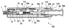
図14は、本発明の実施の形態4によるランセット一体型センサ用測定装置の一例を示す図である。
図14において、11は本発明の実施の形態4によるランセット一体型センサ用測定装置(以下、測定装置と称する。)を示す。13はランセット一体型センサを挿入し、測定の際に指もしくは上腕部に当てる装着口、14は測定装置11に装着されたランセットを駆動するための操作ボタン、12は測定結果等を表示するディスプレイ、15は測定装置11からランセット一体型センサを排出するためのスライドボタン、56は体液を採取する際に不具合が生じた場合に、図14中の矢印A、すなわち、ランセットの駆動方向とは反対方向に引っ張ることにより、ランセット一体型センサを測定装置11に装着した状態のままで測定を行える待機位置に復帰駆動させるプルスティック、57はプルスティック56のストッパーであるとともに、ランセットの針先部の突出量を調節するランセット突出量調節器である。
【0157】
図15は、図14に示したランセット一体型センサ用測定装置のX−X’線断面図であり、この図15ではプルスティック56はつまみ部56dを有するものとなっている。なお、図14で説明したものと同じ構成要素については、同一の符号を付し説明を省略する。
【0158】
図15において、10は測定装置11に装着されたランセット一体型センサであり、人や動物の体液を採取するため、皮膚を突き刺して体液を得るためのランセット2と、採取された体液を分析するためのセンサ1とが一体として構成されたものである。
【0159】
また、19はランセット一体型センサ10を構成するランセット2が有するコネクタ2bとその凹部19aとが互いに嵌合するコネクタ受け、56aは皮膚を穿刺する側と反対側の一端にランセット2の皮膚を穿刺する側と反対側を受けるコネクタ受け19が取り付けられたシャフトであり、そのプルスティック56内に位置する端部(抜け出し防止部材)56bは、プルスティック56のランセット一体型センサ10の開口56cよりも大径となっている。20はコネクタ受け19に設けられた駆動レバーであり、駆動手段100の動作を開始するための操作ボタン14の押圧によりそのロックが解除されるシャフト56aに装着されたばね18によりコネクタ受け19が皮膚を穿刺する方向に移動しようとする付勢力に対しコネクタ受け19の移動を停止する。なお、操作ボタン14、プルスティック56、ランセット突出量調節器57、シャフト56a、コネクタ受け19により、ランセット2をその待機位置よりセンサ1の長手方向に沿って駆動させ、ランセット2が皮膚を穿刺する方向にランセットを駆動させた後、ランセット一体型センサ10を測定装置11に装着したままの状態でランセットを待機位置に復帰駆動させる駆動手段100を構成している。
【0160】
次に、動作について説明する。
患者は先ず、ランセット一体型センサ用測定装置11の装着口13にランセット一体型センサ10を押し込んで、ランセット一体型センサ10のランセット2が有するコネクタ2bをコネクタ受け19の凹部19aと嵌合させるとともに、操作ボタン14を押下することによりランセット2を発射できるように、コネクタ受け19に設けられた駆動レバー20のテーパ状突起(爪部)20aを測定装置11のテーパ状突起(爪部)11cに係止させる。
【0161】
その後、測定装置11の装着口13に被測定者の指もしくは上腕部を当て、操作ボタン14を押すと、コネクタ受け19のテーパ状突起20aと測定装置11のテーパ状突起11cとの係合が外れ、センサ10の先端よりランセット2が発射される。
【0162】
この時、ランセット2が皮膚を突き刺せなかったり、なんらかの不具合で測定がうまく行かなかった場合には、使用者がプルスティック56をつまんで図14の矢印方向、即ち図中の上方に引っ張ることにより、シャフト56aの端部56bが引き上げられランセット2のコネクタ2bを保持するコネクタ受け19がこれに連動して動作し、再度、コネクタ受け19に設けられたテーパ状突起20aを操作ボタン14直前のテーパ状突起11cに係止させることができる。
【0163】
また、ランセット2が発射されると、ランセット2は、センサ1の長手方向に沿って移動し、ランセット1と連動して動作するプルスティック56がランセット突出量調節器57の対向面とぶつかるまで移動する。このプルスティック56のストッパーとして働くランセット突出量調節器57は、例えば、測定装置11の装着口13とは反対側の一側面に形成されたネジ穴11dと螺合するネジ構造をしており、これを左回りあるいは右回りに回転することにより、ランセットの移動方向に沿って移動させることができるものである。
【0164】
このため、測定者は、予めランセット2を駆動させる前にランセット突出量調節器57の位置を調節し、コネクタ受け19とバネストッパー(支持部材)23との距離を調節することによりバネ力を調節し、ランセット2の針部2aが所望の突出量となるよう調節しておく。これにより、発射されたランセット2は、プルスティック56がランセット突出量調節器57に当たって停止するまで移動することとなり、センサから突出するランセット2の針先部の突出量を調節することができる。
【0165】
このように、本実施の形態4によれば、ランセット2が皮膚を突き刺せなかったり、なんらかの不具合で測定がうまく行かなかった場合であっても、ランセット2のコネクタ2bを保持するコネクタ受け19を再度操作ボタン14下に係止し、測定を行える状態にするプルスティック56を設けることにより、再度の測定準備を容易に行うことができる。
また、ランセットの突出量を調節することができるランセット突出量調節器を設けることにより、測定者の体液の出具合を調節したり、痛みを軽減することができる。
【0166】
(実施の形態5)
この実施の形態5はバイオセンサやランセット一体型センサを面倒な操作を必要とすることなく測定装置に装着できるバイオセンサ用のカートリッジを提供するものであり、請求項44ないし請求項46の発明に対応する。
以下に、本発明の実施の形態5によるバイオセンサ用カートリッジについて、電気化学的に血糖値を測定する血糖値測定用のバイオセンサを収納するカートリッジを例に挙げ、図面を参照しながら説明する。
【0167】
図16は、本発明の実施の形態5によるバイオセンサ用カートリッジを示す図である。
図16において、1は例えば血糖値測定用のバイオセンサであり、略長方形状で一方の短辺側が半円弧状である板状部材からなる。11はバイオセンサ1を取り付けて血糖値を測定する測定装置、63はプラスティック等からなるバイオセンサ用カートリッジであり、略直方体状の収納箱(カートリッジ本体)63c内に、バイオセンサ1が測定装置11に挿入される部分を上方に向けて直立支持することで個別に収納できる、バイオセンサ1の形状に合致したスリットからなる収納部63bを複数有する。なお、このバイオセンサ1を収納するための収納部(スリット)63bの間隔は、測定装置11の挿入口11aを、個別に収納されたバイオセンサ1に押し込むことができる,十分な間隔を有する。この間隔は、目的とするバイオセンサ1を測定装置11の挿入口11aに挿入する際、挿入口11aが隣接するバイオセンサに接触しない間隔である。63aはバイオセンサ用カートリッジ63が有する蓋体(蓋部)であり、中空の略直方体形状となっており、収納箱63cの一辺に設けられた蝶番63hをヒンジにしてほぼ90度回転することにより開閉する。
【0168】
図17は、本発明の実施の形態5によるバイオセンサ用カートリッジに収納されたセンサを測定装置に挿入している状態を示す図である。
バイオセンサ1の測定装置11への取り付けは、バイオセンサ用カートリッジ63の蓋体63aを図16に示すように開けた後、図17(a),図17(b)に示すように、バイオセンサ用カートリッジ63に半円弧状の一端を下向けにして収納されているバイオセンサ1を、測定装置11に設けられたバイオセンサ1用の挿入口11aに押し込むことにより行う。
【0169】
その際、バイオセンサ1を収納するための収納部63bの間隔は、目的とするバイオセンサ1を測定装置11の挿入口11aに挿入する際、挿入口11aが隣接するバイオセンサに接触しない間隔に設定されているため、目的とするバイオセンサ1を、他のバイオセンサ1を傷つけることなく容易に測定装置11に取り付け可能である。
【0170】
このように、本実施の形態5によるバイオセンサ用カートリッジによれば、バイオセンサ用カートリッジに設ける個々の収納部の間隔を、測定装置11の挿入口11aに、個別に収納されたバイオセンサ1を押し込むことができる,十分な間隔となるようにしたので、バイオセンサ1を測定装置11にワンタッチで挿入することができ、測定準備を簡易に行うことができ、収納容器に収納されたバイオセンサを面倒な操作を行うことなく測定装置11に挿入することができるとともに、測定装置の挿入口11aが、目的とするバイオセンサに隣接するバイオセンサに接触して破損したりする事故等を、極力抑えることができる効果がある。
【0171】
(実施の形態5の変形例1)
以下に、本発明の実施の形態5の変形例1によるバイオセンサ用カートリッジについて説明する。なお、本変形例1によるバイオセンサ用カートリッジは、カートリッジの密閉の仕方に特徴を有するものであり、他の構成は前述した実施の形態1とほぼ同様であるため、同一の符号を付し、説明を省略する。
【0172】
図18は、本発明の実施の形態5の変形例1によるバイオセンサ用カートリッジを示す図である。
図18(a)に示すようにバイオセンサ用カートリッジ63は、内部が中空となった略直方体状の蓋体63aが、略直方体状の収納箱63cに対しその長手方向に回転軸がスライド可能なヒンジにより回動可能に取り付けられている。
【0173】
このヒンジは蓋体63aの開口の一方の短辺の両端付近から蓋体63aの長辺をなす側面に対し垂直方向に突出する一対の軸状突起63gと、収納箱63cの開口の一方の短辺の両端付近からその開口の長辺に沿いこの長辺をなす側面と同一平面内で延在する横長の軸受け部63iと、この軸受け部63iに長円状に設けられ軸状突起63gが嵌め込まれる軸受け孔63jとからなる。
【0174】
そして、バイオセンサ用カートリッジ63の収納箱63cの上面の各辺の縁部に設けられた突出部(周側縁部)63fの切り欠き63eの4ヶ所に、蓋体63aの開口の各辺の縁部に設けられた逆L字状の突出部63dの4ヶ所の位置を合わせて切り欠き63eに潜り込ませ、矢印の方向、即ち、左回りに90°回転させた後、半径方向に、即ち図中左手前の方向に少しスライドさせることにより、L字状の突出部63dと切り欠き63e付近の突出部63fとが互いに嵌合し、蓋体63aがバイオセンサ用カートリッジ63の収納部を複数有する収納箱63cを密閉する構造となっている。図18(b)は、図18(a)の状態から蓋体を密閉した状態を示す側面図である。
【0175】
また、図18(c)は、バイオセンサ用カートリッジ63の収納箱63cと蓋体63aとの密着部、即ち蓋体63aの開口の周側縁部に、弾性部材(シール部材)64を設けて、容器を密閉させた状態を示す断面図である。なお、弾性部材64とは、ゴム等の弾性力の大きい部材をいう。このように、弾性部材64を一体化成形することにより、バイオセンサ用カートリッジの密閉性を増すことができる。
【0176】
なお、以上の説明では、バイオセンサの収納部の形状に関しては特に述べなかったが、略直方体形状の収納箱63cの凹部を充填する部材に一定間隔でバイオセンサの形状に合ったスリットを設けることにより、実施の形態5と同様に目的とするバイオセンサ1を測定装置2の挿入口2aに挿入する際、挿入口2aが隣接するバイオセンサに接触しない間隔で直立支持するようにすることができる。
【0177】
このように、本実施の形態5の変形例1によれば、バイオセンサ用カートリッジ63の収納箱63cと蓋体63aとの嵌合部に、弾性部材64等を一体化して形成し、蓋体63aを被せた後に、蓋体63aに設けられたL字状の突出部63dをバイオセンサ用カートリッジの突出部63fの切り欠き63eに潜り込ませ、スライドさせて嵌合させ、容器を密閉するようにしたので、容器の密閉性が増し、容器の中の湿気を減少させることができ、センサの湿気による汚染を防止させることができ、センサの精度向上につながる効果がある。
【0178】
(実施の形態5の変形例2)
図19は、本発明の実施の形態5の変形例2によるバイオセンサ用カートリッジを示す図である。
図19において、10は人や動物の皮膚を突き刺して体液を採取するランセットと採取された体液を分析するためのセンサとを一体として構成したランセット一体型センサ、11はランセット一体型センサ5を取り付けて血糖値等の測定を行うランセット一体型センサ用測定装置、63はプラスティック等からなるバイオセンサ用カートリッジであり、略直方体形状の蓋体63aと略直方体形状の収納箱63cとからなる。収納箱63cは底面に保護カバー(プロテクター)3が装着されたランセット一体型センサ10を直立状態で一定間隔で支持できるように、収納箱63cの凹部を充填する部材の最も底面に近い側にランセット一体型センサ10の保護カバー3が嵌入されてこれを支持する下側溝630aが、その上側にランセット一体型センサ10のセンサ部の一部が嵌入されてこれを支持する中間溝630bが、その上側に溝の最下部がやや丸くなって溝の幅が広がりほぼ全体がランセット一体型センサ10のセンサ部より幅広の上側溝630cが設けられており、これら互いにつながった下側溝(第1の溝)630a,中間溝(第2の溝)630b,上側溝(第3の溝)630cにより1つの収納部(溝)63bが形成されている。そして、収納箱63aは複数の収納部63bによりランセット一体型センサ10を、測定装置11に挿入される部分を上側に向けて所定の間隔で並べて個別に収納する。
【0179】
なお、このランセット一体型センサを収納するための収納部の間隔は、測定装置11の挿入口11aを、個別に収納されたランセット一体型センサ10に押し込むことができる,十分な間隔を有するものである。この、ランセット一体型センサの例としては、既に述べた実施の形態1または2に示すものがある。
【0180】
図20(a)は、ランセット一体型センサのランセット一体型センサ用測定装置への取り付けを説明するための状態図であり、図20(b)はその斜視図を示している。
図20(a)は図1等に比べ針収納部がやや太めのランセット一体型センサを示している。
【0181】
ランセット一体型センサ10のランセット一体型センサ用測定装置11への取り付けは、バイオセンサ用カートリッジ63の蓋体63aを図19に示すように開けた後、図20(b)に示すように、バイオセンサ用カートリッジ63に収納されているランセット一体型センサ1に対して、ランセット一体型センサ用測定装置11に設けられたランセット一体型センサの挿入口11aを押し込むことにより行う。
【0182】
このように、本実施の形態5によれば、バイオセンサ用カートリッジに設ける個々の収納部の間隔を、測定装置11の挿入口11aを、個別に収納されたランセット一体型センサ10に押し込むことができる,十分な間隔となるようにしたので、ランセット一体型センサ10をランセット一体型センサ用測定装置11にワンタッチで挿入することができ、ランセットを有さないセンサに対応する測定装置よりもその測定準備を簡易に行うことができ、収納容器に収納されたバイオセンサを面倒な動作を行うことなく測定装置11に挿入することができるとともに、測定装置11の挿入口11aが目的とするバイオセンサに隣接するバイオセンサに接触して破損してしまうことが回避できる効果がある。
【0183】
なお、上記実施の形態5の変形例1または2では、バイオセンサを直立して支持するようにしたが、バイオセンサ用カートリッジの高さを抑えたい場合には、バイオセンサを斜め方向に支持するようにしてもよく、この場合でも、該バイオセンサを挿入して測定を行う測定装置の挿入口を、目的のバイオセンサに隣接するバイオセンサに接触することなく押し込むことができる間隔で、収納部を設けることにより、同様の効果が得られる。
【0184】
産業上の利用可能性
このように、本発明のランセット一体型センサ及びこれと組み合わされる測定装置によれば、センサとランセットとを一体とし、体液の特性を測定するための測定装置に、ランセットを駆動するための機能を持たせたので、従来の、センサ、ランセット、測定装置、そしてランセットデバイスからなるものに比べ、部品の点数が減り、管理がし易くなる。特に、使い捨てにするセンサとランセットの個数を、別々に管理しなくとも良くなり便利である。また携帯するに際しても、嵩張らず、持ち運びに便利となる。
また、測定に際しては、従来のように、センサを測定装置に、ランセットをランセットデバイスにそれぞれセットするような必要はなく、ランセット一体型センサを測定装置へセットする一回きりの操作で行うことができる。また使用済みセンサの取り換え操作についても、その手間は半減する。
さらに、ランセットの針先がセンサ内に収容された状態でロックされるようにしたので、針先が不用意に露出することによる事故を防止できる。
【図面の簡単な説明】
【図1】 本発明の実施の形態1におけるランセット一体型センサを示す図であり、図1(a)はその全体斜視図、図1(b)はその分解斜視図である。
【図2】 同ランセット一体型センサの動作を説明する平面図であり、図2(a)は保護カバーを装着した状態で、針先が突出した状態を示す図、図2(b)は保護カバーを装着した状態で、針先がセンサ内に収容された状態を示す図、図2(c)は保護カバーを外した状態で、針先が突出した状態を示す図、図2(d)は保護カバーを外した状態で、針先がセンサ内に収容された状態を示す図である。
【図3】 本発明の実施の形態1におけるランセット一体型センサに組み合わされる測定装置の斜視図であり、図3(a)はその上面側を示す図、図3(b)はその下面側を示す図である。
【図4】 同測定装置の内部構造を説明する図であり、図4(a)はその下半分側の分解斜視図、図4(b)はその側面の断面図である。
【図5】 同測定装置へのランセット一体型センサの装着動作を説明する図であり、図5(a)はその装着開始時の側面断面図、図5(b)はその装着完了時の側面断面図、図5(c)はその操作ボタン付近の断面図である。
【図6】 本発明の実施の形態1におけるランセット一体型センサの保護カバーを示す図であり、図6(a)はその針先突出時に保護カバーを装着した状態を示す図、図6(b)はその針先収納時にセンサの先端に保護カバーを装着した状態を示す図である。
【図7】 本発明の実施の形態1におけるランセット一体型センサに組み合わされる測定装置の斜視図である。
【図8】 本発明の実施の形態2によるランセット一体型センサを示す図であり、図8(a)はその全体斜視図、図8(b)はその分解斜視図である。
【図9】 本発明の実施の形態2によるランセット一体型センサとランセット一体型センサ用測定装置とを示す図であり、図9(a)はセンサを装着した状態の測定装置の斜視図、図9(b)はセンサを装着した状態の測定装置の断面図である。
【図10】 ランセットに設けられた微小凹部とセンサに設けられた微小凸部との嵌合を説明するための説明図である。
【図11】 本発明の実施の形態3によるランセット一体型センサ用測定装置の外観を示す図であり、図11(a)はホルダー体を装着した状態を示す図、図11(b)はホルダー体を取り外した状態を示す図である。
【図12】 本発明の実施の形態3によるランセット一体型センサ用測定装置のホルダー体の外観を示す図であり、図12(a)はホルダー体を測定装置に装着した状態の正面図、図12(b) はホルダー体を測定装置に装着した状態を上方から見た断面図、図12(c)は測定装置に装着したホルダー体を取り外そうとする状態を上方から見た断面図である。
【図13】 本発明の実施の形態3によるランセット一体型センサ使用するランセット一体型センサ用測定装置の内部構造およびランセット一体型センサの他の構成例を示す図であり、図13(a)はホルダー体を装着した状態の測定装置を示す断面図、図13(b)はホルダー体を装着した状態の測定装置の一部切開断面図である。
【図14】 本発明の実施の形態4によるランセット一体型センサを使用するランセット一体型センサ用測定装置の外観を示す図である。
【図15】 本発明の実施の形態4によるランセット一体型センサ用測定装置の内部構造を示す断面図である。
【図16】 本発明の実施の形態5によるバイオセンサ用カートリッジを示す断面図である。
【図17】 本発明の実施の形態5によるバイオセンサ用カートリッジに収納されたセンサを測定装置に挿入している状態を示す図であり、図17(a)はその挿入時の状態を示す図、図17(b)はその挿入前の状態を示す図である。
【図18】 本発明の実施の形態5の変形例1によるバイオセンサ用カートリッジを示す図であり、図18(a)はその蓋体を開けた状態の斜視図、図18(b)はその蓋体を閉じた状態の側面図、図18(c)は蓋体を閉じた状態の断面図である。
【図19】 本発明の実施の形態5の変形例2によるバイオセンサ用カートリッジを示す図である。
【図20】 本発明の実施の形態5の変形例2によるバイオセンサ用カートリッジにおいてランセット一体型センサのランセット一体型センサ用測定装置への取り付けを説明するための図であり、図20(a)はその取り付け時の状態を示す図、図20(b)はその取り付け前の状態を示す図である。
【図21】 従来のバイオセンサ用測定装置の一例を示す斜視図である。
【図22】 従来のランセットデバイスを示す図であり、図22(a)はその斜視図、図22(b)はその一部を透視した状態での斜視図である。
【図23】 従来の,バイオセンサの保存状態を示す図であり、図23(a)は包材に包装された状態を示す図、図23(b)はプラスティック容器に収納された状態を示す図である。
【図24】 従来の,バイオセンサを測定装置に挿入している状態を示す図である。[0001]
Technical field
The present invention is for collecting body fluids of humans and animals and enabling easy analysis of the characteristics thereof, and in particular, for collecting body fluids, a lancet for piercing the skin to obtain body fluids, and the skin It is related with what improved the lancet integrated sensor characterized by the structure which integrated the sensor for extract | collecting and analyzing the bodily fluid taken out on the surface of this.
[0002]
The present invention also relates to a measuring device for measuring a component of a body fluid such as a blood glucose level, and more particularly to an improvement of the measuring device for a lancet integrated sensor..
[0003]
Background art
Conventionally, as an apparatus for simply analyzing the characteristics of human or animal body fluids, for example, an apparatus for electrochemically measuring blood glucose levels has already been put into practical use.
One of such devices is a biosensor. In the following, this biosensor and a measurement device combined therewith will be described as an example.
[0004]
FIG. 21 shows a state in which an elongated
[0005]
The
In this
[0006]
Normally, blood is pierced through the skin of a part such as a fingertip by using a
In the
[0007]
In addition, biosensors used for analyzing body fluids collected from humans and animals are generally stored in a state where they are packaged in an aluminum packaging material or stored in a plastic container. Biosensors were taken out from materials and plastic containers.
[0008]
FIG. 23 (a) shows that a
[0009]
Then, when performing the measurement, the
[0010]
The conventional biosensor and its measurement apparatus are configured as described above. When performing measurement, the patient first sets a
[0011]
Moreover, since it is necessary to monitor a blood glucose level several times a day, these apparatuses are miniaturized in consideration of portability. However, in the above-described conventional configuration, the
[0012]
The present invention has been made in order to solve the above-described problems of the prior art, and in order to make the operation and management easier and to further improve the portability, the lancet integrated sensor in which the sensor and the lancet are integrated. And a measuring device combined therewith.
[0015]
Disclosure of the invention
That is, in order to solve the conventional problems as described above, a lancet-integrated sensor according to the invention of
[0016]
According to this, the sensor and the lancet are integrated, and the sensor and the lancet can be managed together without being separately managed, and the handling becomes easy.In addition, when the lancet integrated sensor is not attached to the measuring device, the lancet is held at a position where the needle tip is hidden, so there is no risk of infection, etc.Handling is also easy.
[0017]
The lancet integrated sensor according to the invention of
According to this, the lancet is held inside the sensor, and a specific structure for further downsizing the lancet-integrated sensor can be provided.
[0018]
The lancet-integrated sensor according to
According to this, positioning of the lancet and the sensor can be facilitated by the elongated space, and it is possible to secure the attachment space between the sensor and the lancet and the movement space of the lancet.
[0019]
The lancet-integrated sensor according to claim 4 of the present application is the lancet-integrated sensor according to any one of
According to this, it is possible to provide a lancet-integrated sensor that is thinner.
[0020]
The lancet integrated sensor according to
According to this, since the tip of the lancet is housed in the sensor, safety can be further improved.
[0021]
The lancet integrated sensor according to
According to this, it is possible to avoid the danger of damaging the inside of the cavity for collecting body fluid with the lancet.
[0022]
Further, the lancet integrated sensor according to the invention of
According to this, since the body fluid is collected in the space in which the lancet moves to pierce the skin, the lancet-integrated sensor can be further downsized.
[0023]
Further, the lancet integrated sensor according to the invention of claim 8 of the present application is the lancet integrated sensor according to any one of
According to this, since the body fluid is accommodated in the cavity on the tip end side of the sensor from which the needle tip protrudes, the time during which the collected body fluid is exposed to the outside air can be kept short.
[0024]
The lancet integrated sensor according to claim 9 of the present application is the lancet integrated sensor according to any one of
According to this, it becomes possible to electrically measure the characteristics of the body fluid.
[0025]
Further, the lancet integrated sensor according to the invention of
According to this, the characteristics of the body fluid can be connected to the external measuring device and electrically measured.
[0026]
A lancet-integrated sensor according to claim 11 of the present application is6The lancet integrated sensor according to any one of
According to this, the characteristics of the body fluid can be measured optically or electrochemically by a chemical reaction between the reagent and the body fluid.
[0027]
The lancet-integrated sensor according to the invention of
According to this, the external driving means for driving the lancet can perform the piercing operation by grasping the proximal end portion of the lancet and moving the lancet in the longitudinal direction of the sensor.
[0028]
The lancet-integrated sensor according to the invention of
According to this, the external drive means for driving the lancet can more easily grip the end of the lancet, and the lancet can be driven more reliably.
[0029]
The lancet integrated sensor according to claim 14 of the present application is the lancet integrated sensor according to
According to this, the external drive means for driving the lancet can more easily grip the end of the lancet, and the lancet can be driven more reliably.
[0030]
The lancet integrated sensor according to claim 15 of the present application is the lancet integrated sensor according to any one of
Thereby, the injury by the needle tip of a lancet and contamination of the needle tip can be prevented.
[0031]
Further, the lancet integrated sensor according to the invention of
This facilitates the removal of the protective cover that covers the lancet needle tip.
[0032]
The lancet integrated sensor according to claim 17 of the present application is the lancet integrated sensor according to
Accordingly, the sensor and the lancet can be mounted on the measuring device by holding the protective cover without holding the sensor or the lancet.
[0033]
The lancet-integrated sensor according to claim 18 of the present application is the lancet-integrated sensor according to
[0034]
Thereby, it can set so that the front-end | tip may be accommodated in a protection cover with respect to the sensor which was set to the external measuring device and the measurement was complete | finished. And in this state, a used sensor can be removed from a measuring device and can be processed hygienically.
[0035]
The lancet integrated sensor according to claim 19 of the present application is the lancet integrated sensor according to any one of
Accordingly, the outer periphery of the sensor and the lancet is integrally covered with the holder, and the lancet-integrated sensor can be easily handled by holding the holder.
[0036]
The lancet integrated sensor according to claim 20 of the present application is the lancet integrated sensor according to
Thereby, the sensor and the lancet in the holder can be easily confirmed, and handling becomes easier.
[0037]
The lancet integrated sensor according to claim 21 of the present application is the lancet integrated sensor according to any one of
Thus, not only the sensor but also the lancet is always new each time measurement is performed, so that it can be managed hygienically.
[0038]
A measuring device according to the invention of
[0039]
As a result, the conventional lancet device is integrated with the measurement device, and a separate lancet device is not required as in the conventional case, and the puncture operation and measurement can be performed only with the measurement device. . In addition, since a lancet integrated with a sensor is attached to this measuring device every time it is measured, it is only necessary to add a lancet driving means to the conventional measuring device, which can be realized at low cost. it can.
[0040]
The measuring device according to the invention of
[0041]
As a result, the patient performs puncturing of a fingertip or the like with the lancet, spotting on the sensor, or the like using one end of the exposed lancet-integrated sensor as a mark, and the operation becomes easy. In addition, since one end of the lancet-integrated sensor is exposed, it is possible to prevent the measuring device from being contaminated by body fluids or the like.
[0042]
The measuring device according to the invention of
Thereby, since the needle tip of the lancet is accommodated in the sensor, safety can be further improved.
[0043]
The measuring device according to claim 25 of the present application is the measuring device according to
This makes it possible to electrically measure the characteristics of body fluid.
[0044]
A measuring device according to the invention of
[0045]
As a result, the external driving means for driving the lancet grips the end of the lancet, moves the lancet in the longitudinal direction of the sensor, and performs a piercing operation. Further, by providing the holding portion at the end portion, it becomes easier for the driving means to grip.
[0046]
The measuring device according to the invention of claim 27 of the present application is the measuring device according to
As a result, the end portion or the holding portion of the lancet is engaged with the end portion of the spring, and the elastic force of the coil spring is biased to the lancet.
[0047]
The measuring device according to the invention of claim 28 of the present application22Or claim 27EitherThe lancet-integrated sensor measurement apparatus according to any one of
Thereby, the injury by the needle tip of a lancet and contamination of the needle tip can be prevented.
[0048]
A measuring device according to a twenty-ninth aspect of the present invention is the measuring device according to any one of the twenty-second to twenty-eighth aspects, wherein the lancet-integrated sensor according to the nineteenth or twenty-first aspect is detachable. The sensor and the lancet are attached to the measuring device while being held by the holder, and the sensor is held by the connector in accordance with the operation of engaging the holder with the measuring device. The end of the lancet opposite to the needle tip or the gripping portion of the protective cover is configured to be gripped by the driving means.
Accordingly, the outer periphery of the sensor and the lancet is integrally covered with the holder, and the lancet-integrated sensor can be easily handled by holding the holder.
[0049]
A measuring device according to a thirty-third aspect of the present invention is the measuring device according to any one of the twenty-second to twenty-ninth aspects, wherein the used lancet-integrated sensor is an operation of an operation button provided on the measuring device main body. Therefore, it can be removed from the main body of the measuring device without being touched by the hand.
Accordingly, the used lancet-integrated sensor can be removed from the measuring device without touching it with the hand, so that infection can be prevented without soiling the hand.
[0050]
A measuring device according to a thirty-first aspect of the present invention is the measuring device according to any one of the twenty-second to thirty-third aspects, wherein the amount of protrusion of the tip of the lancet from the tip of the sensor is applied to the measuring device main body. It is configured to be able to display on the provided display means.
Thereby, the protrusion amount of the needle tip of the lancet can be more clearly confirmed by the display means, and it becomes easier to use.
[0051]
The lancet-integrated sensor according to the invention of
As a result, the lancet to which the body fluid adheres is locked in the sensor, and the hand can be safely removed from the measuring device without accidentally touching the needle tip.
[0052]
The lancet integrated sensor according to claim 33 of the present application is the lancet integrated sensor according to
As a result, the lancet to which the body fluid adheres is locked in the sensor, and the hand can be safely removed from the measuring device without accidentally touching the needle tip.
[0053]
The lancet-integrated sensor according to the invention of
As a result, the lancet to which the body fluid adheres is locked in the sensor, and the hand can be safely removed from the measuring device without accidentally touching the needle tip.
[0054]
Further, the lancet integrated sensor according to the invention of
As a result, the lancet to which the body fluid adheres is locked in the sensor, and the hand can be safely removed from the measuring device without accidentally touching the needle tip.
[0055]
A lancet-integrated sensor measuring apparatus according to the invention of
[0056]
As a result, the lancet with bodily fluid attached is locked in the sensor, and the lancet integrated sensor that can be safely removed from the measuring device without touching the needle tip part accidentally is measured. Thus, it is possible to realize a measuring apparatus that can house the needle tip portion in the sensor and safely remove it after measurement.
[0057]
The lancet-integrated sensor measuring apparatus according to claim 37 of the present application is the lancet-integrated sensor measuring apparatus according to
[0058]
As a result, the lancet with bodily fluid attached is locked in the sensor, and the lancet integrated sensor that can be safely removed from the measuring device without touching the needle tip part accidentally is measured. Thus, it is possible to realize a measuring apparatus that can house the needle tip portion in the sensor and safely remove it after measurement.
[0059]
Moreover, the measuring device for a lancet-integrated sensor according to the invention of
[0060]
As a result, the holder body can be removed from the measuring device, so that it can be easily replaced and cleaned, and can be used not only as a personal machine but also by other people. It can be used safely and hygienically.
[0061]
A lancet-integrated sensor measurement apparatus according to claim 39 of the present application is the lancet-integrated sensor measurement apparatus according to
As a result, the holder body can always be attached to the measuring device in the normal direction, and the reverse insertion of the lancet-integrated sensor into the measuring device can be prevented.
[0062]
The lancet-integrated sensor measuring apparatus according to claim 40 of the present application is the lancet-integrated sensor measuring apparatus according to
Thereby, the opening of the holder mounting portion is asymmetrical in the vertical direction and the width direction, and there is no mistake in the mounting direction of the holder.
[0063]
The lancet-integrated sensor measurement apparatus according to claim 41 of the present application is the lancet-integrated sensor measurement apparatus according to claim 40, wherein the holder body has a hinge-shaped stopper, The inner side of the stopper is fixed to the holder body, and the outer side of the hinge-shaped stopper is fitted and stopped with the fitting part of the holder mounting part.
As a result, the holder body can always be attached to the measuring device in the normal direction, and the reverse insertion of the lancet-integrated sensor into the measuring device can be prevented.
[0064]
The lancet-integrated sensor measurement device according to claim 42 of the present application is the lancet-integrated sensor measurement device according to claim 40, wherein the holder body is mounted on one side surface of the measurement device. The peripheral edge of the opening excluding the small opening has a peripheral edge extending along the opening surface, and a portion of the peripheral edge corresponding to the small opening has the hinge-shaped portion. A stopper is provided, and the hinge-shaped stopper is formed by extending a belt-like elastic member along the direction in which the lancet-integrated sensor is inserted into the holder body, and bending the elastic member halfway outward by 180 degrees. This is what I did.
Thereby, the holder body is stably attached to the measuring device by the spreading force due to the elasticity of the stopper.
[0065]
The lancet-integrated sensor measurement apparatus according to claim 43 of the present application is the lancet-integrated sensor measurement apparatus according to claim 42, wherein the hinge-shaped stopper is disposed at a tip of the belt-shaped elastic member. The clip member has a thickness greater than that of the elastic member and performs positioning when the holder body is locked to the opening.
Thereby, since the front end side of the stopper is locked inside the small opening of the measuring device, the stopper does not come off from the small opening, and the holder body can be mounted stably.
[0074]
The biosensor cartridge according to the invention of claim 44 of the present application is36. Any one of claims 1-21 and 32-35In the biosensor cartridge containing a plurality of lancet-integrated biosensors, the cartridge main body is provided with a hinge portion at one end of the upper surface thereof for pivotally locking a lid portion covering the upper surface of the cartridge main body. The main body has a plurality of groove portions for supporting each lancet-integrated biosensor in an upright manner, and the plurality of groove portions are connected to an insertion port of a measuring apparatus for performing measurement by inserting the biosensor. The cartridge main body is formed in parallel to each other from the upper surface to the lower surface at intervals that can be inserted without contacting the body biosensor.
[0075]
This makes it easy to install by simply opening the lid and pushing the sensor insertion port of the measuring device into the lancet-integrated sensor. Can be omitted and the usability can be improved.
[0076]
In addition, the claims of this application45The biosensor cartridge according to the present invention is as follows.44In the biosensor cartridge described above, the lancet-integrated biosensor includes a substantially square and narrow protector that protects the lancet protruding from the lancet-integrated biosensor in an unused state, and the lancet can be slid inside. A sensor body having a substantially rectangular shape and semicircular at the front side and wider than the protector, and a connector portion provided on the lancet and projecting rearward from the sensor body and having a width comparable to the sensor body. Each of the plurality of groove portions is provided on the lowermost surface side of the cartridge main body, is provided with a narrow first groove that matches the shape of the protector, and is provided above the first groove. A second groove having a width wider than the first groove and matching the shape of a part of the main body, and provided above the second groove. , Matched to the shape of the insertion opening of the measuring device in which the sensor body is inserted, it is obtained by a and a third groove wider than the second groove, as.
[0077]
As a result, the lancet integrated sensor having a complicated shape can be supported at a distance from each other, and the lancet integrated sensor can be attached by simply pushing the sensor insertion port of the measuring device into the lancet integrated sensor. Therefore, the troublesome measurement preparation of inserting into the measuring apparatus can be omitted, and the usability can be improved.
[0078]
Further, the claims of the present invention46The cartridge for a biosensor according to claim45In the biosensor cartridge described above, the insertion port portion accommodates the sensor body in a gap that penetrates through a columnar protrusion that protrudes from one side of the measurement device, and the insertion portion is in the gap that extends into the measurement device. The connector portion is accommodated.
[0079]
This makes it possible to mount the lancet-integrated sensor with a complicated rear end shape by simply pushing the sensor insertion port of the measuring device, and taking the lancet-integrated sensor and inserting it into the measuring device for each measurement. It saves preparation and improves usability.
[0080]
Further, the claims of the present invention47The lancet-integrated sensor measuring device described inThe method according to any one of
[0081]
As a result, even when the body fluid is collected, even if the skin cannot be pierced or the measurement cannot be performed due to some trouble, the measurement preparation for the lancet-integrated sensor can be easily performed again. The usability of can be improved.
[0082]
Further, the claims of the present invention48The measuring device for a lancet-integrated sensor according to
[0083]
As a result, when collecting body fluid, it is possible to easily prepare for measurement again by operating the pull stick even if the skin cannot be pierced or measurement cannot be performed due to some trouble. The usability of the lancet-integrated sensor measuring device can be improved.
[0084]
Further, the claims of the present invention49The measuring device for a lancet-integrated sensor according to
As a result, the shaft is supported inside the measuring device, and the coil spring is mounted between the support member and the connector receiver, so that the driving force of the lancet can be supplied.
[0085]
Further, the claims of the present invention50The measuring device for a lancet-integrated sensor according to
Thereby, the shaft can be pulled out in the direction opposite to the protruding direction of the lancet by pulling the pull stick.
[0086]
In addition, the claims of this application51The measuring device for a lancet-integrated sensor according to
Thereby, the protrusion amount of the needle tip of the lancet can be adjusted, the degree of exudation of the body fluid of the measurer can be adjusted, and the pain caused by puncture of the lancet can be reduced.
[0087]
In addition, the claims of this application52The measuring device for a lancet-integrated sensor according to
Thereby, since the protrusion amount of the needle tip of the lancet can be adjusted, the degree of exudation of the body fluid of the measurer can be adjusted, and the pain caused by puncture of the lancet can be reduced.
[0088]
BEST MODE FOR CARRYING OUT THE INVENTION
(Embodiment 1)
Hereinafter, an embodiment of the present invention will be specifically described with reference to the drawings, taking as an example a blood glucose level sensor that electrochemically measures blood glucose levels.
[0089]
The first embodiment relates to a lancet-integrated sensor that is easily managed and carried by integrating the lancet and the sensor, and a measuring device for the lancet-integrated sensor that drives and measures the lancet-integrated sensor. This corresponds to the invention of
[0090]
That is, the lancet-integrated sensor according to the first embodiment is obtained by integrating an elongated piece-shaped sensor and a lancet. More specifically, the lancet moves in parallel along the longitudinal direction of the sensor. Such an integrated structure.
[0091]
A lancet driving function of a conventional lancet device is added to the measuring device to which the lancet integrated sensor is attached. That is, it is also provided with driving means for driving the lancet of the attached lancet-integrated sensors.
[0092]
In this configuration, a new lancet-integrated sensor is set in the measuring device every time measurement is performed. Then, the measuring device is gripped, and the driving means is operated to puncture the fingertip with the lancet. Subsequently, the blood sugar level or the like can be measured by the operation of spotting blood on the sensor.
Hereinafter, these lancet-integrated sensors and measuring devices will be described in detail.
[0093]
FIG. 1 shows a perspective view and an exploded perspective view of a lancet-integrated sensor according to
[0094]
[0095]
As shown in FIG. 1B, the
[0096]
A recess along the shape of the
[0097]
Thus, the lancet integrated sensor is formed by bonding the
Thus, the
[0098]
FIG. 2A shows a state where the
[0099]
Here, as shown in FIGS. 2 (a) and 2 (b), the shape of the
[0100]
The above is the configuration of the lancet-integrated sensor. In the measurement, the
[0101]
measuring device
Next, an example of a measuring device combined with the above-described lancet-integrated sensor will be described with reference to the drawings.
FIG. 3 is a perspective view of the measuring
[0102]
FIG. 4A shows a perspective view in a state where the upper side of the outer case is removed in order to show the internal structure of the measuring
[0103]
[0104]
[0105]
[0106]
[0107]
Measurement operation
A series of measurement operations will be described below for the lancet-integrated sensor and the measurement apparatus configured as described above.
First, the operation of mounting the lancet integrated sensor on the measuring device will be described. The lancet-integrated sensor is in the state shown in FIG. That is, the
[0108]
By further pushing the
[0109]
At this time, the
[0110]
When the patient pushes the
[0111]
Next, blood collection operation and blood spotting operation will be described. When the mounting operation of the lancet integrated sensor is completed, the state shown in FIG. The patient holds the measuring
[0112]
Then, when the
[0113]
The patient drops a small amount of blood that oozes from the pierced fingertip onto the tip of the
[0114]
At this time, the
[0115]
Thus, according to the lancet integrated sensor according to the first embodiment, since the sensor and the lancet are integrated, the management thereof is facilitated, and the trouble of exchanging them separately each time they are used can be saved. Since the sensor and the lancet can be set at the same time, the mounting becomes easy and the portable device is not bulky.
[0116]
When discharging the lancet-integrated sensor, in order to prevent injury and infection more reliably, as shown in FIG. 6 (a), the tip of the
[0117]
Further, the lancet integrated sensor according to the first embodiment has a shape in which a protective cover is put on the tip of the lancet, and the lancet integrated sensor and the protective cover are integrally covered and held. It is also possible to provide a holder. In this case, the attachment to the measuring device and the discharging operation from the measuring device can be performed in a state of being covered with the holder, and the operation becomes easier for a patient with a handicapped hand.
Further, if the holder is made of a transparent material so that the lancet-integrated sensor inside can be easily seen, the operability is further improved.
[0118]
Furthermore, in the above-described first embodiment, the lancet-integrated sensor shares the space in which the lancet needle tip moves and the cavity from which blood is sucked, but these can also be configured separately. . In addition, although the sensor has a thin plate shape, the sensor is not limited to this shape and may be formed in a cylindrical shape.
Moreover, as shown in FIG. 7, the
[0119]
(Embodiment 2)
In the second embodiment, when removing the lancet-integrated sensor from the measuring device, the needle tip can be more securely accommodated in the sensor, so that the finger of another person can touch the
Hereinafter, a lancet-integrated sensor according to
[0120]
FIG. 8A is a perspective view showing an example of a lancet-integrated sensor according to
In FIG. 8A,
[0121]
FIG. 8B is an exploded perspective view showing a configuration example of the lancet-integrated sensor according to
As shown in FIG. 8B, the lancet-integrated
[0122]
A
[0123]
Further, as described above, the minute recesses 21a and 21b of the
[0124]
Note that the positional relationship between the minute recesses 21a and 21b and the
[0125]
Further, the tip side of the
[0126]
As with the
[0127]
The lancet-integrated sensor according to the second embodiment of the present invention is provided with a
[0128]
Next, a series of measurement operations of the lancet-integrated sensor and measurement device completed as described above will be described.
First, the operation of mounting the lancet-integrated sensor on the measuring device is as follows. When the lancet-integrated sensor is not used, as shown in FIG. 2A, the
[0129]
At that time, the rear end side of the
[0130]
When the insertion of the lancet-integrated
[0131]
When the
[0132]
Next, blood collection operation and blood spotting operation will be described. When the mounting operation of the lancet integrated sensor is completed, the
[0133]
Therefore, when the push button (lock release member) 14 is pressed, the engagement between the
[0134]
A small amount of blood that has oozed out from the punctured fingertip of the patient or subject is spotted on the tip of the
[0135]
At this time, the discharge lever (discharge member) 22 integrated with the
[0136]
Thus, according to the second embodiment, the discharged lancet-integrated sensor is discharged in a state where the
[0137]
In addition, it is possible to measure body fluid by attaching a lancet integrated sensor that can be safely removed in this way, and when the measurement is completed, the lancet needle is housed in the sensor and discharged outside. A measurement device for a lancet-integrated sensor that can be obtained can be obtained.
[0138]
In the second embodiment, the concave portion is provided on the upper surface of the lancet and the convex portion that fits the concave portion is provided in the
[0139]
(Embodiment 3)
The third embodiment is such that the holder for guiding the lancet-integrated sensor to the inside of the measuring device can be removed from the measuring device and can be cleaned, and corresponds to the inventions of
[0140]
That is, in the lancet-integrated sensor measurement device of the first or second embodiment, when collecting a body fluid, a patient puts a finger or an upper arm portion into the holder-like mounting
[0141]
However, in the measuring apparatus according to the first or second embodiment, the measuring
On the other hand, the measuring device for the lancet-integrated sensor according to the third embodiment makes it possible to clean or replace the attachment port-shaped holder to which the body fluid adheres and to use it safely and hygienically. Is.
[0142]
11 and 12 show the configuration of the lancet-integrated sensor measuring apparatus according to
11A is a perspective view of the lancet-integrated sensor and a measuring device combined therewith, and FIG. 11B shows a state when the holder is removed.
In FIG. 11,
[0143]
The measuring
[0144]
As shown in FIG. 11B, the structure of the
In addition, as described above, the lancet-integrated
Hereinafter, the structure of the
[0145]
FIG. 12 is an explanatory diagram for explaining attachment / detachment between the
In FIG. 12A, 43a and 43b are hinge-shaped stoppers that the
[0146]
The
[0147]
12B and 12C are cross-sectional views when the
[0148]
In this way, by making the holder for attaching the lancet-integrated sensor included in the measuring device detachable, the holder body to which the body fluid is attached can be replaced with an unused one or washed. In addition to a personal measuring instrument, a person other than a normal user can perform measurement without fear of infection or the like, and the lancet-integrated sensor measuring device can be used safely and hygienically.
[0149]
Further, by providing the holder body with a hinge-shaped stopper that is engaged with the holder mounting portion, the holder body can be easily engaged and detached.
Also, by making the holder mounting part hole and the holder body stopper shape different, the holder body can always be mounted in the normal direction with respect to the measuring device, and the lancet integrated sensor is It is possible to prevent reverse insertion.
[0150]
In
[0151]
Further, the
Further, the shape of the lancet-integrated
[0152]
(Embodiment 4)
In the fourth embodiment, the amount of protrusion of the needle tip from the lancet-integrated biosensor can be easily adjusted, and when the lancet is driven to protrude vigorously, the drive stops due to some trouble. And can be easily returned to the state before driving.47Or claims52This corresponds to the invention.
[0153]
In other words, in the lancet-integrated sensor measuring apparatus according to the first or second embodiment, when collecting body fluid, the
[0154]
However, in order to re-drive the
In the lancet-integrated sensor according to the first or second embodiment, there is no effective means for adjusting the protrusion amount of the lancet needle tip, and the body fluid exudation of the measurer can be adjusted and the pain of the measurer can be reduced. It was difficult to do.
[0155]
In contrast, the lancet-integrated sensor measuring apparatus according to the fourth embodiment can easily adjust the protruding amount of the lancet needle tip, and collect body fluid due to insufficient puncture of the lancet or some problem. This makes it possible to easily prepare for measurement again when it is not possible.
A lancet-integrated sensor measurement apparatus according to Embodiment 4 will be described below.
[0156]
FIG. 14 is a diagram showing an example of a lancet-integrated sensor measurement apparatus according to Embodiment 4 of the present invention.
In FIG. 14,
[0157]
15 is a cross-sectional view of the lancet-integrated sensor measuring apparatus shown in FIG. 14 taken along the line X-X ′. In FIG. 15, the
[0158]
In FIG. 15,
[0159]
[0160]
Next, the operation will be described.
First, the patient pushes the lancet-integrated
[0161]
Thereafter, when the finger or upper arm of the person to be measured is applied to the mounting
[0162]
At this time, if the
[0163]
Further, when the
[0164]
Therefore, the measurer adjusts the spring force by adjusting the position of the lancet
[0165]
As described above, according to the fourth embodiment, the
In addition, by providing a lancet protrusion amount adjuster that can adjust the protrusion amount of the lancet, it is possible to adjust the amount of body fluid discharged by the measurer and to reduce pain.
[0166]
(Embodiment 5)
The fifth embodiment provides a cartridge for a biosensor that can be mounted on a measuring device without requiring a troublesome operation of the biosensor or the lancet integrated sensor.46This corresponds to the invention.
Hereinafter, a cartridge for a biosensor according to
[0167]
FIG. 16 is a view showing a biosensor cartridge according to
In FIG. 16, 1 is a biosensor for measuring blood glucose level, for example, and is composed of a plate-like member having a substantially rectangular shape and one short side having a semicircular arc shape.
[0168]
FIG. 17 is a diagram showing a state in which the sensor housed in the biosensor cartridge according to the fifth embodiment of the present invention is inserted into the measurement apparatus.
The
[0169]
At this time, the interval between the
[0170]
As described above, according to the biosensor cartridge according to the fifth embodiment, the interval between the individual storage portions provided in the biosensor cartridge is set to the
[0171]
(
The biosensor cartridge according to
[0172]
FIG. 18 is a diagram showing a biosensor cartridge according to
As shown in FIG. 18 (a), the
[0173]
This hinge has a pair of shaft-
[0174]
The four sides of the opening of the
[0175]
18C, an elastic member (seal member) 64 is provided at the close contact portion between the
[0176]
In the above description, the shape of the storage part of the biosensor is not particularly described, but slits that match the shape of the biosensor are provided at regular intervals on the member that fills the recess of the
[0177]
As described above, according to the first modification of the fifth embodiment, the
[0178]
(
FIG. 19 is a view showing a biosensor cartridge according to the second modification of the fifth embodiment of the present invention.
In FIG. 19,
[0179]
In addition, the space | interval of the accommodating part for accommodating this lancet integrated sensor has sufficient space | interval which can push the
[0180]
FIG. 20A is a state diagram for explaining attachment of the lancet integrated sensor to the measuring device for the lancet integrated sensor, and FIG. 20B is a perspective view thereof.
FIG. 20 (a) shows a lancet-integrated sensor having a slightly thicker needle storage compared to FIG.
[0181]
The lancet-integrated
[0182]
As described above, according to the fifth embodiment, the interval between the individual storage portions provided in the biosensor cartridge can be pushed into the individually integrated
[0183]
In the first or second modification of the fifth embodiment, the biosensor is supported upright. However, when it is desired to suppress the height of the biosensor cartridge, the biosensor is supported in an oblique direction. Even in this case, the storage unit is inserted at an interval at which the insertion port of the measurement device that performs measurement by inserting the biosensor can be pushed without contacting the biosensor adjacent to the target biosensor. By providing the same, the same effect can be obtained.
[0184]
Industrial applicability
Thus, according to the lancet-integrated sensor of the present invention and the measurement device combined therewith, the sensor and the lancet are integrated, and the function for driving the lancet is added to the measurement device for measuring the characteristics of body fluid. Since it is provided, the number of parts is reduced and management is easy as compared with the conventional sensor, lancet, measuring device, and lancet device. In particular, it is convenient because the number of sensors and lancets to be disposed does not have to be managed separately. Moreover, when carrying, it is not bulky and is convenient to carry.
In addition, when performing the measurement, it is not necessary to set the sensor to the measuring device and the lancet to the lancet device as in the conventional case, and it can be performed by a single operation of setting the lancet integrated sensor to the measuring device. it can. Also, the time and effort for replacing the used sensor is halved.
Furthermore, since the lancet needle tip is locked in the state of being accommodated in the sensor, it is possible to prevent accidents due to the needle tip being inadvertently exposed..
[Brief description of the drawings]
1A and 1B are diagrams showing a lancet-integrated sensor according to
FIG. 2 is a plan view for explaining the operation of the lancet-integrated sensor. FIG. 2 (a) is a view showing a state in which a protective cover is attached and a needle tip protrudes, and FIG. 2 (b) is a protection view. FIG. 2 (c) shows a state in which the needle tip is housed in the sensor with the cover attached, FIG. 2 (c) shows a state in which the needle tip protrudes with the protective cover removed, FIG. 2 (d). FIG. 3 is a view showing a state in which a needle tip is housed in a sensor with a protective cover removed.
FIGS. 3A and 3B are perspective views of a measuring device combined with the lancet-integrated sensor according to
4A and 4B are diagrams illustrating the internal structure of the measurement apparatus, in which FIG. 4A is an exploded perspective view of the lower half side, and FIG. 4B is a cross-sectional view of the side surface thereof.
FIGS. 5A and 5B are diagrams for explaining the mounting operation of the lancet-integrated sensor to the measurement apparatus, FIG. 5A is a side cross-sectional view when the mounting is started, and FIG. 5B is a side view when the mounting is completed. FIG. 5C is a cross-sectional view of the vicinity of the operation button.
6 is a view showing a protective cover of the lancet-integrated sensor according to
FIG. 7 is a perspective view of a measuring device combined with the lancet-integrated sensor according to
8A and 8B show a lancet-integrated sensor according to a second embodiment of the present invention. FIG. 8A is an overall perspective view and FIG. 8B is an exploded perspective view.
FIG. 9 is a diagram showing a lancet-integrated sensor and a lancet-integrated sensor measuring device according to
FIG. 10 is an explanatory diagram for explaining the fitting between the minute concave portion provided in the lancet and the minute convex portion provided in the sensor.
11A and 11B are views showing an external appearance of a lancet-integrated sensor measuring apparatus according to
FIG. 12 is a view showing an appearance of a holder body of a lancet-integrated sensor measuring device according to a third embodiment of the present invention, and FIG. 12 (a) is a front view of the state in which the holder body is mounted on the measuring device; 12 (b) is a cross-sectional view of the state in which the holder body is mounted on the measuring device as viewed from above, and FIG. 12 (c) is a cross-sectional view in which the state of attempting to remove the holder body mounted on the measuring device is viewed from above. is there.
FIG. 13 is a diagram showing an internal structure of a measuring device for a lancet-integrated sensor that uses the lancet-integrated sensor according to
FIG. 14 is a diagram showing an appearance of a measuring device for a lancet integrated sensor using the lancet integrated sensor according to a fourth embodiment of the present invention.
FIG. 15 is a cross-sectional view showing the internal structure of a lancet-integrated sensor measuring apparatus according to a fourth embodiment of the present invention.
FIG. 16 is a cross-sectional view showing a biosensor cartridge according to a fifth embodiment of the present invention.
FIG. 17 is a diagram showing a state in which a sensor housed in a biosensor cartridge according to
18A and 18B are diagrams showing a biosensor cartridge according to
FIG. 19 shows a biosensor cartridge according to a second modification of the fifth embodiment of the present invention.
20 is a diagram for explaining the attachment of the lancet integrated sensor to the lancet integrated sensor measuring device in the biosensor cartridge according to the second modification of the fifth embodiment of the present invention; FIG. FIG. 20 is a view showing a state at the time of attachment, and FIG. 20B is a view showing a state before the attachment.
FIG. 21 is a perspective view showing an example of a conventional biosensor measuring apparatus.
22A and 22B are diagrams showing a conventional lancet device, in which FIG. 22A is a perspective view thereof, and FIG. 22B is a perspective view in a state where a part thereof is seen through.
23A and 23B are diagrams showing a storage state of a conventional biosensor, in which FIG. 23A shows a state packaged in a packaging material, and FIG. 23B shows a state stored in a plastic container. FIG.
FIG. 24 is a diagram showing a state in which a conventional biosensor is inserted into a measuring device.
Claims (52)
前記センサ本体は、前記ランセットが前記センサに対して相対的に移動可能なように、前記ランセットを保持し、
前記ランセットは、外部の駆動手段によって駆動されて皮膚を突き刺すことが可能であるとともに、
前記外部の駆動手段に接続されていない場合には、前記センサより突出しない位置に係止されるよう構成された、
ことを特徴とするランセット一体型センサ。A lancet for collecting the body fluid by piercing the skin of the subject and a sensor body for analyzing the collected body fluid are configured integrally.
The sensor body holds the lancet so that the lancet is movable relative to the sensor,
The lancet is driven by an external driving means and can pierce the skin,
When not connected to the external driving means, it is configured to be locked at a position that does not protrude from the sensor.
A lancet-integrated sensor characterized by that.
前記センサ本体は、内部に前記ランセットが貫通可能な空間を有し、
該空間内に前記ランセットを保持する、
ことを特徴とするランセット一体型センサ。The lancet-integrated sensor according to claim 1,
The sensor body has a space through which the lancet can penetrate,
Holding the lancet in the space;
A lancet-integrated sensor characterized by that.
前記センサ本体は、内部に前記ランセットを収納する細長い空間が形成されている、
ことを特徴とするランセット一体型センサ。The lancet-integrated sensor according to claim 2,
The sensor body has an elongated space in which the lancet is housed.
A lancet-integrated sensor characterized by that.
前記センサ本体は、薄片状かつ少なくとも一方に凹部を有する2枚のプレートを貼り合わせてなり、
互いに貼り合わせた該2枚のプレートの凹部により形成された前記空間内に、前記ランセットを収納する、
ことを特徴とするランセット一体型センサ。In the lancet integrated sensor according to any one of claims 1 to 3,
The sensor body is formed by laminating two plates having a flaky shape and at least one concave portion,
Storing the lancet in the space formed by the recesses of the two plates bonded together;
A lancet-integrated sensor characterized by that.
前記ランセットは、皮膚を突き刺し体液を採取する際に、その針先を収納している前記センサ本体の内部より突出する、
ことを特徴とするランセット一体型センサ。In the lancet integrated sensor according to any one of claims 1 to 4,
When the lancet punctures the skin and collects body fluid, the lancet protrudes from the inside of the sensor body that houses the needle tip,
Features and to Lula Nsetto integrated sensor that.
前記体液を採取するキャビティを、前記センサ本体のランセットを収納する空間とは別に備えた、
ことを特徴とするランセット一体型センサ。The lancet-integrated sensor according to any one of claims 1 to 5,
A cavity for collecting the body fluid is provided separately from a space for storing the lancet of the sensor body,
A lancet-integrated sensor characterized by that.
前記センサ本体のランセットを収納する空間は、前記体液を採取するキャビティを兼ね、
該ランセットを収納する空間内に、体液を採取する、
ことを特徴とするランセット一体型センサ。The lancet-integrated sensor according to any one of claims 1 to 5 ,
The space for storing the lancet of the sensor body also serves as a cavity for collecting the body fluid,
Collect body fluid in the space for storing the lancet.
A lancet-integrated sensor characterized by that.
前記ランセットの針先が突出するセンサの先端部側に、体液を採取するキャビティの入口を設けた、
ことを特徴とするランセット一体型センサ。The lancet-integrated sensor according to any one of claims 1 to 6,
Provided with a cavity inlet for collecting body fluid on the tip side of the sensor from which the needle tip of the lancet protrudes,
A lancet-integrated sensor characterized by that.
前記センサ本体は、キャビティ内に体液の特性結果を出力するための電極を備えた、
ことを特徴とするランセット一体型センサ。The lancet-integrated sensor according to any one of claims 1 to 8,
The sensor body includes an electrode for outputting a characteristic result of body fluid in the cavity.
A lancet-integrated sensor characterized by that.
体液の特性を電気的に測定するため、外部の測定装置と接続される接続端子を前記キャビティを有するセンサ本体の一端に備えた、
ことを特徴とするランセット一体型センサ。The lancet-integrated sensor according to claim 9,
In order to electrically measure the characteristics of the body fluid, a connection terminal connected to an external measurement device is provided at one end of the sensor body having the cavity.
A lancet-integrated sensor characterized by that.
前記キャビティ内に、採取した体液と反応する試薬を備えた、
ことを特徴とするランセット一体型センサ。The lancet-integrated sensor according to any one of claims 6 to 10,
A reagent that reacts with the collected body fluid is provided in the cavity.
A lancet-integrated sensor characterized by that.
前記ランセットは、その針先とは反対側の端部が前記センサ本体より突出しており、
該突出した端部が外部の測定装置の駆動手段と係合して駆動され、皮膚の突き刺し動作が行われる、
ことを特徴とするランセット一体型センサ。The lancet-integrated sensor according to any one of claims 1 to 10,
The end of the lancet opposite to the needle tip protrudes from the sensor body,
The protruding end is driven by being engaged with a driving means of an external measuring device, and a skin piercing operation is performed.
A lancet-integrated sensor characterized by that.
前記ランセットの針先と反対側の端部には、前記外部の測定装置の駆動手段と嵌合するコネクタが設られ、
該コネクタが前記駆動手段と嵌合して、皮膚の突き刺し動作が行われる、
ことを特徴とするランセット一体型センサ。The lancet-integrated sensor according to claim 12,
The end of the lancet opposite to the needle tip is provided with a connector that fits with the driving means of the external measuring device,
The connector is fitted with the driving means, and a skin piercing operation is performed.
A lancet-integrated sensor characterized by that.
前記コネクタは樹脂により形成され、前記ランセットに比べ大径な形状を有する、
ことを特徴とするランセット一体型センサ。The lancet-integrated sensor according to claim 13,
The connector is made of resin and has a larger diameter than the lancet.
A lancet-integrated sensor characterized by that.
前記ランセットの針先には取り外し可能な保護カバーが取り付けられ、
該保護カバーはランセットの突き刺し動作時には取り除かれる、
ことを特徴とするランセット一体型センサ。The lancet-integrated sensor according to any one of claims 1 to 14,
A removable protective cover is attached to the needle tip of the lancet,
The protective cover is removed during the lancet piercing operation.
A lancet-integrated sensor characterized by that.
前記保護カバーは、内部に前記針先を収容する筒状部と、該筒状部の前記針先の先端側に、前記ランセットからの取り外しを容易にする幅広の把持部とを有する、
ことを特徴とするランセット一体型センサ。The lancet-integrated sensor according to claim 15,
The protective cover includes a cylindrical portion that accommodates the needle tip therein, and a wide grip portion that facilitates removal from the lancet on the distal end side of the needle tip of the cylindrical portion.
A lancet-integrated sensor characterized by that.
前記ランセットと前記駆動手段との係合および該ランセットと一体となるセンサ本体の前記測定装置への装着は、前記保護カバーの把持部を掴みながら行う、
ことを特徴とするランセット一体型センサ。The lancet-integrated sensor according to claim 15,
The engagement between the lancet and the driving means and the attachment of the sensor body integrated with the lancet to the measuring device are performed while grasping the grip portion of the protective cover.
A lancet-integrated sensor characterized by that.
前記筒状部は、その内部に前記センサ本体の先端部を収納可能な空間が形成されている、ことを特徴とするランセット一体型センサ。The lancet-integrated sensor according to claim 16,
A lancet-integrated sensor according to claim 1, wherein the cylindrical part has a space in which the tip of the sensor body can be stored.
該ランセット一体型センサは、
前記センサ本体と前記ランセットの周囲を覆い該センサ本体およびランセットを保持するホルダーを備えた、
ことを特徴とするランセット一体型センサ。The lancet-integrated sensor according to any one of claims 1 to 18,
The lancet integrated sensor is
A holder that covers the sensor body and the lancet and holds the sensor body and the lancet;
A lancet-integrated sensor characterized by that.
前記ホルダーを透明な材料により形成した、
ことを特徴とするランセット一体型センサ。The lancet-integrated sensor according to claim 19,
The holder is made of a transparent material,
A lancet-integrated sensor characterized by that.
該ランセット一体型センサは、体液の採取およびその分析を一回行った後に廃棄する、使い捨てタイプである、
ことを特徴とするランセット一体型センサ。The lancet-integrated sensor according to any one of claims 1 to 20,
The lancet-integrated sensor is a disposable type that is discarded after collecting body fluid and analyzing it once.
A lancet-integrated sensor characterized by that.
前記ランセット一体型センサが該測定装置に装着された後に、前記ランセットを駆動して、皮膚を突き刺すためのランセット駆動手段を備えた、
ことを特徴とする測定装置。 A lancet integrated sensor according to any one of claims 1 to 21, wherein the lancet integrated sensor is detachably attached, and is a measuring device for measuring characteristics of body fluid collected by the lancet integrated sensor,
After the lancet-integrated sensor is mounted on the measurement device, the lancet driving means is provided to drive the lancet and pierce the skin.
A measuring device.
前記ランセット一体型センサは、前記測定装置への装着が完了した時点で、少なくともその一端が該測定装置より露出している、
ことを特徴とする測定装置。The measuring device according to claim 22,
The lancet-integrated sensor has at least one end exposed from the measuring device when the mounting to the measuring device is completed.
A measuring device.
前記ランセット駆動手段は、体液を採取するため皮膚を突き刺す時のみ、センサよりその針先が突出し、それ以外は、前記針先がセンサの内部に収納されるように、前記ランセット一体型センサのランセットを駆動する、
ことを特徴とする測定装置。24. The measuring device according to claim 22 or claim 23,
The lancet driving means is a lancet of the lancet-integrated sensor so that the needle tip protrudes from the sensor only when the skin is pierced to collect body fluid, and otherwise the needle tip is housed inside the sensor. Driving,
A measuring device.
該測定装置は、前記ランセット一体型センサのセンサ本体の一端に設けられた電極端子との電気的接続を保つためのコネクタを備え、採取した体液の特性を内部の電気回路にて測定し得るように構成した、
ことを特徴とする測定装置。The measuring device according to claim 24,
The measuring device includes a connector for maintaining electrical connection with an electrode terminal provided at one end of the sensor body of the lancet-integrated sensor so that the characteristics of the collected body fluid can be measured by an internal electric circuit. Configured
A measuring device.
前記ランセット駆動手段は、ランセットの針先とは反対側の端部と係合するか、あるいは前記保護カバーの把持部を把持することにより、前記ランセットの駆動を行う、
ことを特徴とする測定装置。The measuring device according to any one of claims 22 to 25, wherein the lancet-integrated sensor according to any one of claims 15 to 17 is mounted .
The lancet driving means drives the lancet by engaging with the end of the lancet opposite to the needle tip or by holding the grip portion of the protective cover.
A measuring device.
前記ランセット駆動手段は、ランセットをセンサの長手方向に付勢するバネを有しており、測定装置本体に設けた押し釦により、前記バネの付勢力を解除して、ランセットを突き出すようにした、
ことを特徴とする測定装置。The measuring device according to claim 26, wherein
The lancet driving means has a spring for urging the lancet in the longitudinal direction of the sensor, and the urging force of the spring is released by a push button provided on the measuring device main body so as to protrude the lancet.
A measuring device.
請求項15ないし請求項18のいずれかに記載されたランセット一体型センサが着脱可能に取り付けられ、
ランセットの先端に保護カバーを被せた状態で、ランセット一体型センサの測定装置への装着が行われ、センサが該測定装置のコネクタに保持され、ランセットの針先とは反対側の端部が前記ランセット駆動手段に把持されるように構成した、
ことを特徴とする測定装置。The measuring device according to any one of claims 22 to 27,
The lancet-integrated sensor according to any one of claims 15 to 18 is detachably attached,
The lancet integrated sensor is attached to the measuring device with the protective cover on the tip of the lancet, the sensor is held by the connector of the measuring device, and the end opposite to the needle tip of the lancet is Configured to be gripped by the lancet drive means,
A measuring device.
請求項19または請求項20に記載されたランセット一体型センサが着脱可能に取り付けられ、
センサとランセットとは、ホルダーに保持されたままの状態で、測定装置への装着が行われるように、ホルダーを測定装置へ係合させる動作に合わせて、センサがコネクタに保持され、ランセットの針先とは反対側の端部あるいは前記保護カバーの把持部が前記駆動手段に把持されるように構成した、
ことを特徴とする測定装置。The measuring device according to any one of claims 22 to 28,
The lancet-integrated sensor according to claim 19 or claim 20 is detachably attached,
The sensor and the lancet are held by the connector in accordance with the operation of engaging the holder with the measuring device so that the sensor and the lancet are attached to the measuring device while being held by the holder. The end portion on the opposite side or the grip portion of the protective cover is configured to be gripped by the driving means.
A measuring device.
使用済みのランセット一体型センサは、測定装置本体に設けた操作釦の操作により、手で触れることなく、測定装置本体から取り外されるように構成した、
ことを特徴とする測定装置。30. The measuring device according to any one of claims 22 to 29,
The used lancet-integrated sensor is configured to be removed from the measuring device main body without touching it by the operation of the operation button provided on the measuring device main body.
A measuring device.
ランセットの針先の、センサの先端からの突出量を、測定装置本体に設けた表示手段に表示できるように構成した、
ことを特徴とする測定装置。The measuring device according to any one of claims 22 to 30,
The amount of protrusion of the tip of the lancet from the tip of the sensor is configured to be displayed on the display means provided in the measuring device body.
A measuring device.
該センサには、内部に前記ランセットの一部を摺動可能に収容する空隙が形成され、
前記ランセットに対し、前記皮膚を穿刺する方向とは反対方向に力を印加して前記センサ内に前記針部を収納することにより、前記ランセットと前記センサとが相互にロックされる、
ことを特徴とするランセット一体型センサ。In a lancet-integrated sensor having a needle portion and configured to integrate a lancet that punctures the skin and collects body fluid and a sensor for analyzing the collected body fluid,
In the sensor, a gap that slidably accommodates a part of the lancet is formed inside,
By applying a force to the lancet in a direction opposite to the direction of puncturing the skin and storing the needle portion in the sensor, the lancet and the sensor are mutually locked.
A lancet-integrated sensor characterized by that.
前記ランセットは略長方形状の板状部材からなり、
前記ランセットの針部は前記板状部材の一方の短辺側の中央付近に該板状部材の長手方向に沿って突出するように配設され、
前記空隙は前記ランセットをその長手方向に沿って所定量スライドさせた際の輪郭形状と略同一の形状に形成され、
前記センサの先端および後端に、それぞれ前記針部および前記ランセットの他方の短辺を該センサの外部に突出させる開口が形成されている、
ことを特徴とするランセット一体型センサ。The lancet-integrated sensor according to claim 32,
The lancet is composed of a substantially rectangular plate member,
The needle part of the lancet is disposed so as to protrude along the longitudinal direction of the plate member in the vicinity of the center of one short side of the plate member,
The gap is formed in substantially the same shape as the contour shape when the lancet is slid a predetermined amount along its longitudinal direction,
Openings for projecting the other short side of the needle portion and the lancet to the outside of the sensor are formed at the front end and the rear end of the sensor, respectively.
A lancet-integrated sensor characterized by that.
前記ランセットにはロック用凸部,ロック用凹部の何れか一方が、前記センサには前記ロック用凸部,ロック用凹部の何れか一方と嵌合するロック用凹部,ロック用凸部の何れか一方が、それぞれ形成され、
前記ランセットとセンサとのロックは、前記ロック用凸部と前記ロック用凹部とが嵌合することにより行われる、
ことを特徴とするランセット一体型センサ。The lancet-integrated sensor according to claim 32 or claim 33,
The lancet has one of a locking convex portion and a locking concave portion, and the sensor has either a locking concave portion or a locking convex portion that fits with either the locking convex portion or the locking concave portion. One is formed,
The locking of the lancet and the sensor is performed by fitting the locking convex portion and the locking concave portion,
A lancet-integrated sensor characterized by that.
前記ランセットはその2つの長辺から幅方向に突出する2つの平板状の突起部が形成され、
該突起部はその上面に前記ロック用凹部が形成され、
前記センサの内部に形成された、前記ランセットを摺動可能に収容する空隙は、その幅方向に突出し前記ランセットの前記2つの突起部を収容する2つの窪み部を有し、
該窪み部はその天井面に前記ロック用凸部が形成されている、
ことを特徴とするランセット一体型センサ。The lancet-integrated sensor according to claim 34,
The lancet is formed with two flat projections protruding in the width direction from the two long sides,
The protrusion has the locking recess formed on the upper surface thereof,
A gap formed inside the sensor to slidably accommodate the lancet has two recesses that project in the width direction and accommodate the two protrusions of the lancet,
The recess is formed with the locking projection on the ceiling surface.
A lancet-integrated sensor characterized by that.
前記測定装置の一側面の開口から挿入された前記ランセット一体型センサを該測定装置内部で案内しその進行方向を規制する案内部材と、
前記測定装置内でバネ部材により前記ランセット一体型センサの挿入方向とは反対方向に押圧付勢され、前記案内部材によって該測定装置の内部に向けて案内されてきた前記ランセットの他方の短辺と嵌合し該ランセットを前記開口に向けて押圧付勢するランセット付勢部材と、
前記ランセット一体型センサが前記測定装置のより内部側に挿入された時前記ランセット付勢部材を該測定装置内の所定位置で固定するロック部材と、
手動操作により前記ロック部材による前記ランセット付勢部材の固定を解除するロック解除用部材と、
前記ランセット付勢部材および前記案内部材の間に設けられ、手動操作により、前記ランセット一体型センサの前記センサを前記開口側に向けて押圧付勢するための排出用部材とを備えた、
ことを特徴とするランセット一体型センサ用測定装置。A measurement device that performs measurement using the lancet-integrated sensor according to claim 33,
A guide member that guides the lancet-integrated sensor inserted from the opening on one side of the measuring device inside the measuring device and restricts its traveling direction;
The other short side of the lancet, which is pressed and biased by a spring member in the measuring device in a direction opposite to the insertion direction of the lancet-integrated sensor and guided toward the inside of the measuring device by the guide member, A lancet biasing member that fits and presses and biases the lancet toward the opening;
A lock member for fixing the lancet urging member at a predetermined position in the measuring device when the lancet-integrated sensor is inserted further into the measuring device;
An unlocking member for releasing the fixing of the lancet urging member by the locking member by manual operation;
A discharge member that is provided between the lancet biasing member and the guide member, and that presses and biases the sensor of the lancet-integrated sensor toward the opening by manual operation;
A lancet-integrated sensor measuring device.
前記排出用部材は、前記測定装置の主面上に露出した操作レバーを前記開口側に向けてスライド操作することにより、該操作レバーと一体の押圧部材が前記ランセット一体型センサの前記皮膚を穿刺する側とは反対側の端部の両側辺近傍を押圧し、該ランセット一体型センサを排出する、
ことを特徴とするランセット一体型センサ用測定装置。The lancet-integrated sensor measuring device according to claim 36,
The discharge member slides the operation lever exposed on the main surface of the measuring device toward the opening, so that the pressing member integral with the operation lever punctures the skin of the lancet-integrated sensor. Pressing the vicinity of both sides of the end opposite to the side to be discharged, and discharging the lancet-integrated sensor,
A lancet-integrated sensor measuring device.
該ランセット一体型センサ用測定装置は、その一側面に開口が設けられ、
前記ランセット一体型センサ用測定装置は、前記開口に対応して設けられ内部に前記ランセット一体型センサを収容可能な空隙を有し、
前記開口を有する一側面には、内部を前記ランセット一体型センサが通過可能な筒状のホルダー体を、前記ランセット一体型センサ用測定装置に対し着脱自在に装着するホルダー装着部が形成され、
前記ホルダー体は、前記ランセット一体型センサ用測定装置を前記空隙内に収容する際に、該ランセット一体型センサを案内し、収容後は前記ランセット一体型センサの上記皮膚を穿刺する側の一端の近傍部分を保持する、
ことを特徴とするランセット一体型センサ用測定装置。 A lancet-integrated sensor measuring apparatus that performs measurement using the lancet-integrated sensor according to any one of claims 1 to 21 ,
The lancet-integrated sensor measuring device has an opening on one side surface,
The lancet-integrated sensor measuring device has a gap that is provided corresponding to the opening and can accommodate the lancet-integrated sensor inside.
On one side surface having the opening, a holder mounting portion is formed, in which a cylindrical holder body through which the lancet integrated sensor can pass is detachably mounted to the measurement device for the lancet integrated sensor,
The holder body guides the lancet-integrated sensor when the lancet-integrated sensor measuring device is accommodated in the gap, and after the accommodation, at one end of the lancet-integrated sensor on the side that punctures the skin. Keep the neighborhood,
A lancet-integrated sensor measuring device.
前記ホルダーと、前記ホルダー装着部との、相互の嵌合部は、上下方向、或は左右方向において非対称な形状を有し、
前記ホルダー装着部に対する前記ホルダーの上下の向きが或る方向である場合のみ、前記ホルダー装着部に対する前記ホルダーの装着が可能となる、
ことを特徴とするランセット一体型センサ用測定装置。The lancet-integrated sensor measuring device according to claim 38,
The fitting portion between the holder and the holder mounting portion has an asymmetric shape in the vertical direction or the horizontal direction,
Only when the vertical orientation of the holder with respect to the holder mounting portion is in a certain direction, the holder can be mounted on the holder mounting portion.
A lancet-integrated sensor measuring device.
前記ホルダー体が装着される前記ホルダー装着部の開口は、角部に相当する部分が丸められた横長の略長方形状を有し、縦方向の2辺の中央付近には幅方向に張り出した小開口をそれぞれ有する、
ことを特徴とするランセット一体型センサ用測定装置。The lancet-integrated sensor measuring device according to claim 38,
The opening of the holder mounting portion on which the holder body is mounted has a horizontally long, substantially rectangular shape with rounded corners corresponding to the corners. Each having an opening,
A lancet-integrated sensor measuring device.
前記ホルダー体は、ヒンジ形状のストッパーを有し、
該ヒンジ形状のストッパーの内側辺が前記ホルダー体に固定され、
前記ヒンジ形状のストッパーの外側辺が前記ホルダー装着部の嵌合部と嵌合停止する、
ことを特徴とするランセット一体型センサ用測定装置。The lancet-integrated sensor measuring device according to claim 40,
The holder body has a hinge-shaped stopper,
The inner side of the hinge-shaped stopper is fixed to the holder body,
The outer side of the hinge-shaped stopper stops fitting with the fitting portion of the holder mounting portion,
A lancet-integrated sensor measuring device.
前記ホルダー体は、前記測定装置の一側面に装着される側の、前記小開口を除く前記開口の周縁部に該開口面に沿って延在する周側縁部を有し、
該周側縁部の前記小開口に対応する部分には、前記ヒンジ形状のストッパーが設けられ、
該ヒンジ形状のストッパーは、帯状の弾性部材を前記ホルダー体へのランセット一体型センサの嵌入方向に沿って延在させ該弾性部材を途中でほぼ180度外側に向けて折り曲げてなる、
ことを特徴とするランセット一体型センサ用測定装置。The lancet-integrated sensor measuring device according to claim 40,
The holder body has a peripheral edge extending along the opening surface at a peripheral edge portion of the opening excluding the small opening, on a side attached to one side surface of the measuring device,
The hinge-shaped stopper is provided in a portion corresponding to the small opening of the peripheral edge,
The hinge-shaped stopper is formed by extending a belt-shaped elastic member along the direction in which the lancet-integrated sensor is inserted into the holder body, and bending the elastic member halfway outward by 180 degrees.
A lancet-integrated sensor measuring device.
前記ヒンジ形状のストッパーは、前記帯状の弾性部材の先端部に該弾性部材より厚みを有し、前記ホルダー体を前記開口に係止させた際の位置決めを行うクリップ部材を有する、
ことを特徴とするランセット一体型センサ用測定装置。The lancet-integrated sensor measurement device according to claim 42,
The hinge-shaped stopper has a clip member that is thicker than the elastic member at a distal end portion of the band-shaped elastic member and performs positioning when the holder body is locked to the opening.
A lancet-integrated sensor measuring device.
上記カートリッジ本体はその上面の一端に、当該カートリッジ本体の上面を覆う蓋部を回動自在に軸止する蝶番部が設けられ、
上記カートリッジ本体は、各ランセット一体型バイオセンサをそれぞれ直立して支持する溝部を、複数有し、
上記複数の溝部は、上記バイオセンサを挿入して測定を行う測定装置の挿入口を、隣接するランセット一体型バイオセンサに接触することなく差し込むことができる間隔で、上記カートリッジ本体の上面から下面に向けて、互いに平行に形成されている、
ことを特徴とするバイオセンサ用カートリッジ。A biosensor cartridge that houses a plurality of lancet-integrated biosensors according to any one of claims 1 to 21 and 32 to 35 ,
The cartridge body is provided at one end of its upper surface with a hinge portion for pivotally locking the lid portion covering the upper surface of the cartridge body,
The cartridge body has a plurality of grooves that support each lancet-integrated biosensor upright,
The plurality of groove portions are spaced from the upper surface to the lower surface of the cartridge body at intervals that allow insertion of an insertion port of a measurement device that performs measurement by inserting the biosensor without contacting an adjacent lancet-integrated biosensor. Are formed parallel to each other,
A biosensor cartridge characterized by the above.
上記ランセット一体型バイオセンサは、未使用状態において該ランセット一体型バイオセンサより突出しているランセットを保護する略正方形かつ幅狭のプロテクターと、
内部に上記ランセットを滑動自在に収容する略長方形状かつ先頭側が半円状で上記プロテクターより幅広のセンサ本体と、
上記ランセットに設けられ上記センサ本体より後方に突出し、上記センサ本体と同程度の幅を有するコネクタ部とを有し、
上記複数の溝部はそれぞれ、
上記カートリッジ本体の最も下面側に設けられ、上記プロテクターの形状に合致した、幅狭の第1の溝と、
該第1の溝より上側に設けられ、上記センサ本体の一部の形状に合致した、上記第1の溝より幅広の第2の溝と、
該第2の溝より上側に設けられ、上記センサ本体が挿入される上記測定装置の挿入口部の形状に合致した、上記第2の溝より幅広の第3の溝とからなる、
ことを特徴とするバイオセンサ用カートリッジ。45. The biosensor cartridge according to claim 44 , wherein
The lancet-integrated biosensor has a substantially square and narrow protector that protects the lancet protruding from the lancet-integrated biosensor in an unused state;
A sensor body having a substantially rectangular shape that slidably accommodates the lancet inside and a semicircular shape on the front side and wider than the protector,
A connector part provided on the lancet, projecting rearward from the sensor body, and having a width comparable to the sensor body;
Each of the plurality of grooves is
A narrow first groove provided on the lowermost side of the cartridge body and conforming to the shape of the protector;
A second groove having a width wider than the first groove, which is provided above the first groove and matches a shape of a part of the sensor body;
A third groove that is provided above the second groove and matches the shape of the insertion port of the measuring device into which the sensor body is inserted, and is wider than the second groove.
A biosensor cartridge characterized by the above.
上記挿入口部は、測定装置に一側面より突出する柱状突起内を貫通する空隙に上記センサ本体を収容し、
上記測定装置内に延在する上記空隙内に上記コネクタ部が収容される、
ことを特徴とするバイオセンサ用カートリッジ。The cartridge for a biosensor according to claim 45 ,
The insertion port accommodates the sensor body in a gap penetrating through a columnar protrusion protruding from one side of the measuring device,
The connector portion is accommodated in the gap extending in the measuring device.
A biosensor cartridge characterized by the above.
前記ランセットを、その待機位置より、前記センサの長手方向に沿って、該ランセットが上記皮膚を穿刺する方向に駆動させる駆動手段が設けられ、
前記駆動手段は、上記ランセットが上記皮膚を穿刺する方向に、前記ランセットを駆動させた後、該ランセット一体型センサを該ランセット一体型センサ用測定装置に装着した状態のままで、前記ランセットを上記待機位置に復帰駆動させることが可能なものである、
ことを特徴とするランセット一体型センサ用測定装置。 A lancet-integrated sensor measuring device that performs measurement by mounting the lancet-integrated sensor according to any one of claims 1 to 21 ,
Drive means is provided for driving the lancet from its standby position along the longitudinal direction of the sensor in a direction in which the lancet punctures the skin,
The drive means drives the lancet in a direction in which the lancet punctures the skin, and then the lancet is attached to the measurement device for the lancet-integrated sensor while the lancet is attached to the lancet-integrated sensor. It can be driven back to the standby position.
A lancet-integrated sensor measuring device.
前記駆動手段は、
その上記皮膚を穿刺する側の一端に、上記ランセットの上記皮膚を穿刺する側と反対側を受けるコネクタ受けが取り付けられたシャフトを有し、
該シャフトの上記皮膚を穿刺する側と反対側の一端に、上記ランセットを上記皮膚を穿刺する方向と反対の方向に復帰駆動させるプルスティックが設けられ、
上記コネクタ受けには、該駆動手段の動作を開始するための操作ボタンの押圧により、そのロックが解除される、上記シャフトに装着されたばねにより上記コネクタ受けが上記皮膚を穿刺する方向に移動しようとする付勢力に対し、該コネクタ受けの移動を停止する爪部が設けられている、
ことを特徴とするランセット一体型センサ用測定装置。The lancet-integrated sensor measurement device according to claim 47 ,
The driving means includes
A shaft on which a connector receiver for receiving the side opposite to the side of puncturing the skin of the lancet is attached to one end of the side of puncturing the skin;
At one end of the shaft opposite to the side where the skin is punctured, a pull stick is provided to drive the lancet back in the direction opposite to the direction of puncturing the skin,
The connector receiver is unlocked by pressing an operation button for starting the operation of the driving means. The spring is attached to the shaft so that the connector receiver moves in the direction of puncturing the skin. A claw portion is provided to stop the movement of the connector receiver against the biasing force
A lancet-integrated sensor measuring device.
該測定装置はその内部の空間に、前記シャフトをその中央付近で摺動自在に支持する支持部材を有し、
前記ばねは、コイルばねであり、前記シャフトの前記支持部材と前記コネクタ受けとの間に装着されている、
ことを特徴とするランセット一体型センサ用測定装置。The lancet-integrated sensor measuring device according to claim 48 ,
The measuring device has a support member that slidably supports the shaft in the vicinity of the center in the space inside the measuring device,
The spring is a coil spring and is mounted between the support member of the shaft and the connector receiver.
A lancet-integrated sensor measuring device.
前記プルスティックは、上記皮膚を穿刺する側の端部に開口が形成され、
前記シャフトは、上記皮膚を穿刺する側とは反対側が前記開口を介して前記プルスティック内に出没自在に収容され、
前記シャフトの上記皮膚を穿刺する側と反対側の端部は、該端部が前記プルスティック内より上記皮膚を穿刺する側に抜け出すのを防止する抜け出し防止部材を有する、
ことを特徴とするランセット一体型センサ用測定装置。The lancet-integrated sensor measuring device according to claim 48 ,
The pull stick has an opening formed at an end on the side where the skin is punctured,
The shaft is accommodated so that the side opposite to the side where the skin is punctured can freely move in and out of the pull stick through the opening,
The end of the shaft opposite to the side where the skin is punctured has a slip-out preventing member that prevents the end from slipping out from the inside of the pull stick to the side where the skin is punctured.
A lancet-integrated sensor measuring device.
前記駆動手段は、
該ランセット一体型センサ用測定装置と上記プルスティックとの間に設けられ、前記ランセットの皮膚を穿刺する針部の突出量を調節するランセット突出量調節器を備えた、
ことを特徴とするランセット一体型センサ用測定装置。The lancet-integrated sensor measuring device according to claim 48 ,
The driving means includes
A lancet protrusion amount adjuster that is provided between the lancet-integrated sensor measuring device and the pull stick and adjusts the protrusion amount of a needle portion that punctures the skin of the lancet;
A lancet-integrated sensor measuring device.
前記プルスティックは、略円筒形状を有し、上記皮膚を穿刺する側と反対側の端部側には一部が当該円筒状部よりも大径となったつまみ部が形成されており、
前記ランセット突出量調節器は、略円筒状の形状を有し、上記皮膚を穿刺する側と反対側の端部に前記プルスティックの前記円筒状部と同径の開口が形成され、
該開口を介して前記円筒状部を摺動自在に収容し、本ランセット一体型センサ用測定装置の前記ランセットの上記皮膚を穿刺する側と反対側の一側面に該測定装置の内部に向けて形成されたねじ穴と螺合し、該螺合方向あるいはその逆方向に回転することにより、前記ランセットの突出量を調節する、
ことを特徴とするランセット一体型センサ用測定装置。The lancet-integrated sensor measurement device according to claim 51 ,
The pull stick has a substantially cylindrical shape, and a knob part having a diameter larger than that of the cylindrical part is formed on the end side opposite to the side where the skin is punctured.
The lancet protrusion amount adjuster has a substantially cylindrical shape, and an opening having the same diameter as the cylindrical portion of the pull stick is formed at an end opposite to the side where the skin is punctured.
The cylindrical portion is slidably accommodated through the opening, and is directed toward the inside of the measuring device on one side surface of the lancet integrated sensor measuring device opposite to the skin puncture side. Screwed with the formed screw hole, and adjusted in the screwing direction or the opposite direction, thereby adjusting the protruding amount of the lancet;
A lancet-integrated sensor measuring device.
Applications Claiming Priority (3)
| Application Number | Priority Date | Filing Date | Title |
|---|---|---|---|
| JP2001011275 | 2001-01-19 | ||
| JP2001011275 | 2001-01-19 | ||
| PCT/JP2002/000386 WO2002056769A1 (en) | 2001-01-19 | 2002-01-21 | Lancet-integrated sensor, measurer for lancet-integrated sensor, and cartridge |
Related Child Applications (1)
| Application Number | Title | Priority Date | Filing Date |
|---|---|---|---|
| JP2008123488A Division JP2008188458A (en) | 2001-01-19 | 2008-05-09 | Cartridge for biosensor |
Publications (2)
| Publication Number | Publication Date |
|---|---|
| JPWO2002056769A1 JPWO2002056769A1 (en) | 2004-05-20 |
| JP4197433B2 true JP4197433B2 (en) | 2008-12-17 |
Family
ID=18878428
Family Applications (4)
| Application Number | Title | Priority Date | Filing Date |
|---|---|---|---|
| JP2002557282A Expired - Fee Related JP4197433B2 (en) | 2001-01-19 | 2002-01-21 | Lancet integrated sensor and measuring device for lancet integrated sensor |
| JP2008123488A Pending JP2008188458A (en) | 2001-01-19 | 2008-05-09 | Cartridge for biosensor |
| JP2010036648A Expired - Lifetime JP5255007B2 (en) | 2001-01-19 | 2010-02-22 | Lancet drive device and lancet device |
| JP2010058227A Expired - Lifetime JP4512171B1 (en) | 2001-01-19 | 2010-03-15 | Device for driving the lancet |
Family Applications After (3)
| Application Number | Title | Priority Date | Filing Date |
|---|---|---|---|
| JP2008123488A Pending JP2008188458A (en) | 2001-01-19 | 2008-05-09 | Cartridge for biosensor |
| JP2010036648A Expired - Lifetime JP5255007B2 (en) | 2001-01-19 | 2010-02-22 | Lancet drive device and lancet device |
| JP2010058227A Expired - Lifetime JP4512171B1 (en) | 2001-01-19 | 2010-03-15 | Device for driving the lancet |
Country Status (5)
| Country | Link |
|---|---|
| US (8) | US7691071B2 (en) |
| EP (1) | EP1285629B1 (en) |
| JP (4) | JP4197433B2 (en) |
| CN (4) | CN102512183B (en) |
| WO (1) | WO2002056769A1 (en) |
Cited By (1)
| Publication number | Priority date | Publication date | Assignee | Title |
|---|---|---|---|---|
| CN101879430B (en) * | 2010-04-30 | 2012-09-26 | 南京航空航天大学 | Ultrasonic reactor based on diffuse sound field |
Families Citing this family (222)
| Publication number | Priority date | Publication date | Assignee | Title |
|---|---|---|---|---|
| US7828749B2 (en) | 1996-05-17 | 2010-11-09 | Roche Diagnostics Operations, Inc. | Blood and interstitial fluid sampling device |
| US7235056B2 (en) | 1996-05-17 | 2007-06-26 | Amira Medical | Body fluid sampling device and methods of use |
| US20020010406A1 (en) | 1996-05-17 | 2002-01-24 | Douglas Joel S. | Methods and apparatus for expressing body fluid from an incision |
| US7666150B2 (en) | 1996-05-17 | 2010-02-23 | Roche Diagnostics Operations, Inc. | Blood and interstitial fluid sampling device |
| EP1579814A3 (en) | 1996-05-17 | 2006-06-14 | Roche Diagnostics Operations, Inc. | Methods and apparatus for sampling and analyzing body fluid |
| US6036924A (en) | 1997-12-04 | 2000-03-14 | Hewlett-Packard Company | Cassette of lancet cartridges for sampling blood |
| US6391005B1 (en) | 1998-03-30 | 2002-05-21 | Agilent Technologies, Inc. | Apparatus and method for penetration with shaft having a sensor for sensing penetration depth |
| DE10010694A1 (en) | 2000-03-04 | 2001-09-06 | Roche Diagnostics Gmbh | Lancet including tipped needle with body surrounding tip |
| DE10053974A1 (en) | 2000-10-31 | 2002-05-29 | Roche Diagnostics Gmbh | Blood collection system |
| DE10057832C1 (en) * | 2000-11-21 | 2002-02-21 | Hartmann Paul Ag | Blood analysis device has syringe mounted in casing, annular mounting carrying needles mounted behind test strip and being swiveled so that needle can be pushed through strip and aperture in casing to take blood sample |
| US8641644B2 (en) | 2000-11-21 | 2014-02-04 | Sanofi-Aventis Deutschland Gmbh | Blood testing apparatus having a rotatable cartridge with multiple lancing elements and testing means |
| BR0206604A (en) | 2001-01-22 | 2004-02-17 | Hoffmann La Roche | Lancet device that has capillary action |
| US7310543B2 (en) * | 2001-03-26 | 2007-12-18 | Kumetrix, Inc. | Silicon microprobe with integrated biosensor |
| DE60229988D1 (en) | 2001-06-08 | 2009-01-02 | Roche Diagnostics Gmbh | Removal device for Körperflussigkeiten |
| US9795747B2 (en) | 2010-06-02 | 2017-10-24 | Sanofi-Aventis Deutschland Gmbh | Methods and apparatus for lancet actuation |
| US7682318B2 (en) | 2001-06-12 | 2010-03-23 | Pelikan Technologies, Inc. | Blood sampling apparatus and method |
| US9226699B2 (en) | 2002-04-19 | 2016-01-05 | Sanofi-Aventis Deutschland Gmbh | Body fluid sampling module with a continuous compression tissue interface surface |
| US8337419B2 (en) | 2002-04-19 | 2012-12-25 | Sanofi-Aventis Deutschland Gmbh | Tissue penetration device |
| EP1404234B1 (en) | 2001-06-12 | 2011-02-09 | Pelikan Technologies Inc. | Apparatus for improving success rate of blood yield from a fingerstick |
| US7025774B2 (en) | 2001-06-12 | 2006-04-11 | Pelikan Technologies, Inc. | Tissue penetration device |
| US7981056B2 (en) | 2002-04-19 | 2011-07-19 | Pelikan Technologies, Inc. | Methods and apparatus for lancet actuation |
| DE60234598D1 (en) | 2001-06-12 | 2010-01-14 | Pelikan Technologies Inc | SELF-OPTIMIZING LANZET DEVICE WITH ADAPTANT FOR TEMPORAL FLUCTUATIONS OF SKIN PROPERTIES |
| US9427532B2 (en) | 2001-06-12 | 2016-08-30 | Sanofi-Aventis Deutschland Gmbh | Tissue penetration device |
| US7749174B2 (en) | 2001-06-12 | 2010-07-06 | Pelikan Technologies, Inc. | Method and apparatus for lancet launching device intergrated onto a blood-sampling cartridge |
| ATE485766T1 (en) | 2001-06-12 | 2010-11-15 | Pelikan Technologies Inc | ELECTRICAL ACTUATING ELEMENT FOR A LANCET |
| DE10134650B4 (en) | 2001-07-20 | 2009-12-03 | Roche Diagnostics Gmbh | System for taking small amounts of body fluid |
| DE10142232B4 (en) * | 2001-08-29 | 2021-04-29 | Roche Diabetes Care Gmbh | Process for the production of an analytical aid with a lancet and test element |
| WO2003039369A1 (en) | 2001-09-26 | 2003-05-15 | Roche Diagnostics Gmbh | Method and apparatus for sampling bodily fluid |
| DE20213607U1 (en) | 2002-02-21 | 2003-07-03 | Hartmann Paul Ag | Blood analyzer for the determination of an analyte |
| US7175642B2 (en) | 2002-04-19 | 2007-02-13 | Pelikan Technologies, Inc. | Methods and apparatus for lancet actuation |
| US8360992B2 (en) | 2002-04-19 | 2013-01-29 | Sanofi-Aventis Deutschland Gmbh | Method and apparatus for penetrating tissue |
| US7892183B2 (en) | 2002-04-19 | 2011-02-22 | Pelikan Technologies, Inc. | Method and apparatus for body fluid sampling and analyte sensing |
| US7909778B2 (en) | 2002-04-19 | 2011-03-22 | Pelikan Technologies, Inc. | Method and apparatus for penetrating tissue |
| US8221334B2 (en) | 2002-04-19 | 2012-07-17 | Sanofi-Aventis Deutschland Gmbh | Method and apparatus for penetrating tissue |
| US7229458B2 (en) | 2002-04-19 | 2007-06-12 | Pelikan Technologies, Inc. | Method and apparatus for penetrating tissue |
| US8267870B2 (en) | 2002-04-19 | 2012-09-18 | Sanofi-Aventis Deutschland Gmbh | Method and apparatus for body fluid sampling with hybrid actuation |
| US8784335B2 (en) | 2002-04-19 | 2014-07-22 | Sanofi-Aventis Deutschland Gmbh | Body fluid sampling device with a capacitive sensor |
| US7491178B2 (en) * | 2002-04-19 | 2009-02-17 | Pelikan Technologies, Inc. | Method and apparatus for penetrating tissue |
| US7976476B2 (en) | 2002-04-19 | 2011-07-12 | Pelikan Technologies, Inc. | Device and method for variable speed lancet |
| US7371247B2 (en) | 2002-04-19 | 2008-05-13 | Pelikan Technologies, Inc | Method and apparatus for penetrating tissue |
| US9248267B2 (en) | 2002-04-19 | 2016-02-02 | Sanofi-Aventis Deustchland Gmbh | Tissue penetration device |
| US8702624B2 (en) | 2006-09-29 | 2014-04-22 | Sanofi-Aventis Deutschland Gmbh | Analyte measurement device with a single shot actuator |
| US7291117B2 (en) | 2002-04-19 | 2007-11-06 | Pelikan Technologies, Inc. | Method and apparatus for penetrating tissue |
| US7674232B2 (en) | 2002-04-19 | 2010-03-09 | Pelikan Technologies, Inc. | Method and apparatus for penetrating tissue |
| US7232451B2 (en) | 2002-04-19 | 2007-06-19 | Pelikan Technologies, Inc. | Method and apparatus for penetrating tissue |
| US7226461B2 (en) | 2002-04-19 | 2007-06-05 | Pelikan Technologies, Inc. | Method and apparatus for a multi-use body fluid sampling device with sterility barrier release |
| US9314194B2 (en) | 2002-04-19 | 2016-04-19 | Sanofi-Aventis Deutschland Gmbh | Tissue penetration device |
| US7297122B2 (en) | 2002-04-19 | 2007-11-20 | Pelikan Technologies, Inc. | Method and apparatus for penetrating tissue |
| US7648468B2 (en) | 2002-04-19 | 2010-01-19 | Pelikon Technologies, Inc. | Method and apparatus for penetrating tissue |
| US7331931B2 (en) | 2002-04-19 | 2008-02-19 | Pelikan Technologies, Inc. | Method and apparatus for penetrating tissue |
| US8579831B2 (en) | 2002-04-19 | 2013-11-12 | Sanofi-Aventis Deutschland Gmbh | Method and apparatus for penetrating tissue |
| US7892185B2 (en) | 2002-04-19 | 2011-02-22 | Pelikan Technologies, Inc. | Method and apparatus for body fluid sampling and analyte sensing |
| US7717863B2 (en) | 2002-04-19 | 2010-05-18 | Pelikan Technologies, Inc. | Method and apparatus for penetrating tissue |
| US9795334B2 (en) | 2002-04-19 | 2017-10-24 | Sanofi-Aventis Deutschland Gmbh | Method and apparatus for penetrating tissue |
| US7547287B2 (en) | 2002-04-19 | 2009-06-16 | Pelikan Technologies, Inc. | Method and apparatus for penetrating tissue |
| US7901362B2 (en) | 2002-04-19 | 2011-03-08 | Pelikan Technologies, Inc. | Method and apparatus for penetrating tissue |
| US20030223906A1 (en) † | 2002-06-03 | 2003-12-04 | Mcallister Devin | Test strip container system |
| WO2004004565A1 (en) * | 2002-07-02 | 2004-01-15 | Arkray, Inc. | Unit for piercing, and piercing device |
| JP4250695B2 (en) * | 2002-07-02 | 2009-04-08 | アークレイ株式会社 | Method for setting puncture member to puncture device, and puncture device |
| US7192405B2 (en) * | 2002-09-30 | 2007-03-20 | Becton, Dickinson And Company | Integrated lancet and bodily fluid sensor |
| US7381184B2 (en) | 2002-11-05 | 2008-06-03 | Abbott Diabetes Care Inc. | Sensor inserter assembly |
| US7731900B2 (en) | 2002-11-26 | 2010-06-08 | Roche Diagnostics Operations, Inc. | Body fluid testing device |
| ES2522972T3 (en) | 2002-12-23 | 2014-11-19 | F.Hoffmann-La Roche Ag | Device for testing body fluids |
| US8052926B2 (en) * | 2002-12-27 | 2011-11-08 | Roche Diagnostics Operations, Inc. | Method for manufacturing a sterilized lancet integrated biosensor |
| US7815579B2 (en) * | 2005-03-02 | 2010-10-19 | Roche Diagnostics Operations, Inc. | Dynamic integrated lancing test strip with sterility cover |
| US7214200B2 (en) * | 2002-12-30 | 2007-05-08 | Roche Diagnostics Operations, Inc. | Integrated analytical test element |
| EP1581116B1 (en) * | 2002-12-30 | 2010-04-07 | Roche Diagnostics GmbH | Capilary tube tip design to assist blood flow |
| EP1581115B1 (en) * | 2002-12-30 | 2009-10-14 | Roche Diagnostics GmbH | Blood acquisition suspension system |
| US8574895B2 (en) | 2002-12-30 | 2013-11-05 | Sanofi-Aventis Deutschland Gmbh | Method and apparatus using optical techniques to measure analyte levels |
| DE10302501A1 (en) * | 2003-01-23 | 2004-08-05 | Roche Diagnostics Gmbh | Device and method for absorbing a body fluid for analysis purposes |
| EP1628567B1 (en) | 2003-05-30 | 2010-08-04 | Pelikan Technologies Inc. | Method and apparatus for fluid injection |
| DK1633235T3 (en) | 2003-06-06 | 2014-08-18 | Sanofi Aventis Deutschland | Apparatus for sampling body fluid and detecting analyte |
| WO2006001797A1 (en) | 2004-06-14 | 2006-01-05 | Pelikan Technologies, Inc. | Low pain penetrating |
| JPWO2004110275A1 (en) * | 2003-06-12 | 2006-07-27 | 松下電器産業株式会社 | Biological information measuring device and biological information measuring method |
| DE10345663A1 (en) * | 2003-06-27 | 2005-01-20 | Senslab-Gesellschaft Zur Entwicklung Und Herstellung Bioelektrochemischer Sensoren Mbh | Diagnostic or analytical disposable with integrated lancet |
| DE10332488A1 (en) * | 2003-07-16 | 2005-02-24 | Roche Diagnostics Gmbh | Analyzer and analysis method for body fluids |
| US7617932B2 (en) * | 2003-09-19 | 2009-11-17 | Diabetes Diagnostics, Inc. | Medical device package, kit and associated methods |
| US8282576B2 (en) | 2003-09-29 | 2012-10-09 | Sanofi-Aventis Deutschland Gmbh | Method and apparatus for an improved sample capture device |
| JP2005111135A (en) * | 2003-10-10 | 2005-04-28 | Asahi Polyslider Co Ltd | Lancet cassette, lancet projection device, and lancet assembly constituted with them |
| EP1680014A4 (en) | 2003-10-14 | 2009-01-21 | Pelikan Technologies Inc | Method and apparatus for a variable user interface |
| KR100823946B1 (en) * | 2003-10-29 | 2008-04-22 | 아크레이 인코퍼레이티드 | Lancet and Centesis Instrument |
| USD914881S1 (en) | 2003-11-05 | 2021-03-30 | Abbott Diabetes Care Inc. | Analyte sensor electronic mount |
| WO2005046477A2 (en) * | 2003-11-12 | 2005-05-26 | Facet Technologies, Llc | Lancing device and multi-lancet cartridge |
| US7070425B2 (en) * | 2003-12-10 | 2006-07-04 | Ennova Direct, Inc. | Thumb drive with retractable USB connector |
| US6979210B2 (en) * | 2003-12-10 | 2005-12-27 | Ennova Direct, Inc. | Thumb drive with retractable USB connector |
| JP4482318B2 (en) * | 2003-12-15 | 2010-06-16 | パナソニック株式会社 | Puncture needle cartridge |
| US7822454B1 (en) | 2005-01-03 | 2010-10-26 | Pelikan Technologies, Inc. | Fluid sampling device with improved analyte detecting member configuration |
| EP1706026B1 (en) | 2003-12-31 | 2017-03-01 | Sanofi-Aventis Deutschland GmbH | Method and apparatus for improving fluidic flow and sample capture |
| US7819283B2 (en) * | 2004-02-18 | 2010-10-26 | Universal Biosensors Pty Ltd | Strip ejection system |
| WO2005104949A1 (en) * | 2004-04-15 | 2005-11-10 | Roche Diagnostics Gmbh | Integrated spot monitoring device with fluid sensor |
| CA2562353C (en) | 2004-04-16 | 2012-03-20 | Facet Technologies, Llc | Cap displacement mechanism for lancing device and multi-lancet cartridge |
| US8828203B2 (en) | 2004-05-20 | 2014-09-09 | Sanofi-Aventis Deutschland Gmbh | Printable hydrogels for biosensors |
| US9775553B2 (en) | 2004-06-03 | 2017-10-03 | Sanofi-Aventis Deutschland Gmbh | Method and apparatus for a fluid sampling device |
| EP1765194A4 (en) | 2004-06-03 | 2010-09-29 | Pelikan Technologies Inc | Method and apparatus for a fluid sampling device |
| JP4500109B2 (en) * | 2004-06-04 | 2010-07-14 | パナソニック株式会社 | Puncture tool |
| JP4500110B2 (en) * | 2004-06-04 | 2010-07-14 | パナソニック株式会社 | Puncture needle cartridge cassette and blood collection puncture device |
| US7299081B2 (en) | 2004-06-15 | 2007-11-20 | Abbott Laboratories | Analyte test device |
| US7766845B2 (en) | 2004-06-21 | 2010-08-03 | Roche Diagnostics Operations, Inc. | Disposable lancet and lancing cap combination for increased hygiene |
| US7837633B2 (en) * | 2004-06-30 | 2010-11-23 | Facet Technologies, Llc | Lancing device and multi-lancet cartridge |
| DE102004033219A1 (en) | 2004-07-09 | 2006-02-02 | Roche Diagnostics Gmbh | Method for the selective sterilization of diagnostic test elements |
| US7727166B2 (en) | 2004-07-26 | 2010-06-01 | Nova Biomedical Corporation | Lancet, lancet assembly and lancet-sensor combination |
| US7645241B2 (en) * | 2004-09-09 | 2010-01-12 | Roche Diagnostics Operations, Inc. | Device for sampling bodily fluids |
| US7604604B2 (en) * | 2004-09-09 | 2009-10-20 | Roche Diagnostics Operations, Inc. | Device for sampling bodily fluids |
| US7488298B2 (en) * | 2004-10-08 | 2009-02-10 | Roche Diagnostics Operations, Inc. | Integrated lancing test strip with capillary transfer sheet |
| US9259175B2 (en) | 2006-10-23 | 2016-02-16 | Abbott Diabetes Care, Inc. | Flexible patch for fluid delivery and monitoring body analytes |
| US8512243B2 (en) * | 2005-09-30 | 2013-08-20 | Abbott Diabetes Care Inc. | Integrated introducer and transmitter assembly and methods of use |
| US8333714B2 (en) | 2006-09-10 | 2012-12-18 | Abbott Diabetes Care Inc. | Method and system for providing an integrated analyte sensor insertion device and data processing unit |
| US7731657B2 (en) | 2005-08-30 | 2010-06-08 | Abbott Diabetes Care Inc. | Analyte sensor introducer and methods of use |
| US8029441B2 (en) | 2006-02-28 | 2011-10-04 | Abbott Diabetes Care Inc. | Analyte sensor transmitter unit configuration for a data monitoring and management system |
| US20090105569A1 (en) | 2006-04-28 | 2009-04-23 | Abbott Diabetes Care, Inc. | Introducer Assembly and Methods of Use |
| US7697967B2 (en) | 2005-12-28 | 2010-04-13 | Abbott Diabetes Care Inc. | Method and apparatus for providing analyte sensor insertion |
| US9788771B2 (en) | 2006-10-23 | 2017-10-17 | Abbott Diabetes Care Inc. | Variable speed sensor insertion devices and methods of use |
| US10226207B2 (en) | 2004-12-29 | 2019-03-12 | Abbott Diabetes Care Inc. | Sensor inserter having introducer |
| US9743862B2 (en) | 2011-03-31 | 2017-08-29 | Abbott Diabetes Care Inc. | Systems and methods for transcutaneously implanting medical devices |
| US7883464B2 (en) | 2005-09-30 | 2011-02-08 | Abbott Diabetes Care Inc. | Integrated transmitter unit and sensor introducer mechanism and methods of use |
| US9572534B2 (en) | 2010-06-29 | 2017-02-21 | Abbott Diabetes Care Inc. | Devices, systems and methods for on-skin or on-body mounting of medical devices |
| US9398882B2 (en) | 2005-09-30 | 2016-07-26 | Abbott Diabetes Care Inc. | Method and apparatus for providing analyte sensor and data processing device |
| US8571624B2 (en) | 2004-12-29 | 2013-10-29 | Abbott Diabetes Care Inc. | Method and apparatus for mounting a data transmission device in a communication system |
| US8652831B2 (en) | 2004-12-30 | 2014-02-18 | Sanofi-Aventis Deutschland Gmbh | Method and apparatus for analyte measurement test time |
| US7479118B2 (en) * | 2005-02-07 | 2009-01-20 | Roche Diagnostics Operations, Inc. | Lancet protective cap |
| US7935063B2 (en) * | 2005-03-02 | 2011-05-03 | Roche Diagnostics Operations, Inc. | System and method for breaking a sterility seal to engage a lancet |
| JP4576624B2 (en) * | 2005-03-02 | 2010-11-10 | 独立行政法人産業技術総合研究所 | Needle integrated biosensor |
| US7695442B2 (en) * | 2005-04-12 | 2010-04-13 | Roche Diagnostics Operations, Inc. | Integrated lancing test strip with retractable lancet |
| US9332938B2 (en) * | 2005-03-02 | 2016-05-10 | Roche Diabetes Care, Inc. | Flat lancet immobilization |
| DE602006020033D1 (en) * | 2005-04-28 | 2011-03-24 | Panasonic Corp | NADELEINFÜHRINSTRUMENT |
| EP1900321A4 (en) * | 2005-06-27 | 2010-09-22 | Nat Inst Of Advanced Ind Scien | Needle integrating biosensor |
| JP4595070B2 (en) * | 2005-06-27 | 2010-12-08 | 独立行政法人産業技術総合研究所 | Needle integrated biosensor |
| JP4893921B2 (en) * | 2005-06-27 | 2012-03-07 | 独立行政法人産業技術総合研究所 | Biosensor |
| JP4547535B2 (en) * | 2005-06-27 | 2010-09-22 | 独立行政法人産業技術総合研究所 | Needle integrated biosensor |
| JP4586210B2 (en) * | 2005-06-27 | 2010-11-24 | 独立行政法人産業技術総合研究所 | Needle integrated biosensor |
| JP4576628B2 (en) * | 2005-07-13 | 2010-11-10 | 独立行政法人産業技術総合研究所 | Needle integrated biosensor |
| US20100081968A1 (en) * | 2005-07-15 | 2010-04-01 | Home Diagnostics, Inc. | Test Strip With Integrated Lancet |
| US8636672B2 (en) * | 2007-02-28 | 2014-01-28 | Nipro Diagnostics, Inc. | Test strip with integrated lancet |
| FI121698B (en) * | 2005-07-19 | 2011-03-15 | Ihq Innovation Headquarters Oy | Health monitoring device and sensor cartridge for the health monitoring device |
| US9521968B2 (en) | 2005-09-30 | 2016-12-20 | Abbott Diabetes Care Inc. | Analyte sensor retention mechanism and methods of use |
| US8057404B2 (en) * | 2005-10-12 | 2011-11-15 | Panasonic Corporation | Blood sensor, blood testing apparatus, and method for controlling blood testing apparatus |
| JP4935286B2 (en) * | 2005-10-12 | 2012-05-23 | パナソニック株式会社 | Blood sensor |
| WO2007057704A1 (en) * | 2005-11-21 | 2007-05-24 | Inverness Medical Switzerland Gmbh | Test device |
| US8105244B2 (en) * | 2005-11-30 | 2012-01-31 | Abbott Diabetes Care Inc. | Integrated sensor for analyzing biological samples |
| WO2007063948A1 (en) * | 2005-12-01 | 2007-06-07 | Arkray, Inc. | Sensor/lancet integrated device and method of collecting body fluid using the same |
| US11298058B2 (en) | 2005-12-28 | 2022-04-12 | Abbott Diabetes Care Inc. | Method and apparatus for providing analyte sensor insertion |
| EP1968432A4 (en) | 2005-12-28 | 2009-10-21 | Abbott Diabetes Care Inc | Medical device insertion |
| WO2007077930A1 (en) | 2006-01-05 | 2007-07-12 | Matsushita Electric Industrial Co., Ltd. | Blood test apparatus |
| WO2007086843A2 (en) * | 2006-01-25 | 2007-08-02 | Nova Biomedical Corporation | Lancet sensor assembly and meter |
| EP1980203B8 (en) * | 2006-01-31 | 2014-06-11 | Panasonic Healthcare Co., Ltd. | Blood sensor and blood test apparatus having the same |
| JP4686763B2 (en) * | 2006-01-31 | 2011-05-25 | 独立行政法人産業技術総合研究所 | Needle integrated biosensor |
| JP4706063B2 (en) * | 2006-01-31 | 2011-06-22 | 独立行政法人産業技術総合研究所 | Needle integrated biosensor |
| JP4670013B2 (en) * | 2006-02-03 | 2011-04-13 | 独立行政法人産業技術総合研究所 | Biosensor and manufacturing method thereof |
| JP4665135B2 (en) * | 2006-02-03 | 2011-04-06 | 独立行政法人産業技術総合研究所 | Biosensor manufacturing method |
| JP4649594B2 (en) * | 2006-02-03 | 2011-03-09 | 独立行政法人産業技術総合研究所 | Biosensor and manufacturing method thereof |
| JP4822511B2 (en) * | 2006-02-09 | 2011-11-24 | 独立行政法人産業技術総合研究所 | Needle integrated biosensor |
| JP4635260B2 (en) * | 2006-03-16 | 2011-02-23 | 独立行政法人産業技術総合研究所 | Biosensor and manufacturing method thereof |
| CN101410058A (en) * | 2006-04-03 | 2009-04-15 | 泉株式会社 | Lancet assembly |
| BRPI0709939A2 (en) * | 2006-04-03 | 2011-08-02 | Izumi Cosmo Co Ltd | lancet mount |
| FR2899482A1 (en) * | 2006-04-11 | 2007-10-12 | Becton Dickinson France Soc Pa | Automatic medicament/product injection device for patient, has safety shield coupled to housing, and provided in active state at end of needle insertion step before which product/medicament injection step is not started |
| JP2007282863A (en) * | 2006-04-17 | 2007-11-01 | Sumitomo Electric Ind Ltd | Biosensor chip |
| JP4953139B2 (en) | 2006-04-17 | 2012-06-13 | 住友電気工業株式会社 | Biosensor chip |
| JPWO2007145205A1 (en) * | 2006-06-13 | 2009-10-29 | 泉株式会社 | Lancet assembly |
| FI124480B (en) * | 2006-07-19 | 2014-09-15 | Mendor Oy | Laitekotelointi |
| JP4871083B2 (en) * | 2006-09-27 | 2012-02-08 | テルモ株式会社 | Body fluid collection unit |
| JP5011936B2 (en) * | 2006-10-11 | 2012-08-29 | パナソニック株式会社 | Blood test equipment |
| US8052618B2 (en) * | 2006-10-15 | 2011-11-08 | Roche Diagnostics Operations, Inc. | Diagnostic test element and process for its production |
| JP4924923B2 (en) * | 2006-11-01 | 2012-04-25 | 住友電気工業株式会社 | Sensor cartridge |
| EP2098167A1 (en) | 2006-12-19 | 2009-09-09 | National Institute Of Advanced Industrial Science and Technology | Biosensor cartridge, method of using biosensor cartridge, biosensor device and needle-integrated sensor |
| WO2008082987A2 (en) * | 2006-12-26 | 2008-07-10 | Abbott Diabetes Care Inc | Analyte meter protectors and methods |
| CA2675275C (en) | 2007-01-12 | 2013-06-25 | Facet Technologies, Llc | Multi-lancet cartridge and lancing device |
| EP2123222A4 (en) * | 2007-01-17 | 2013-10-09 | Panasonic Corp | Blood inspection device |
| WO2008105373A1 (en) | 2007-02-26 | 2008-09-04 | National Institute Of Advanced Industrial Science And Technology | Sensor device |
| WO2008111933A1 (en) * | 2007-03-12 | 2008-09-18 | Bayer Healthcare Llc | Single-sensor meter system with no sensor handling and method of using the same |
| EP1970006A1 (en) | 2007-03-14 | 2008-09-17 | Roche Diagnostics GmbH | Analysis system for determining a analyte in a body fluid and disposable integrated sample extraction and analysis element |
| JP4979005B2 (en) * | 2007-05-28 | 2012-07-18 | 住友電気工業株式会社 | Biosensor measuring device |
| WO2008150917A1 (en) | 2007-05-31 | 2008-12-11 | Abbott Diabetes Care, Inc. | Insertion devices and methods |
| JP4958291B2 (en) * | 2007-07-09 | 2012-06-20 | 住友電気工業株式会社 | Sensor chip measuring device |
| WO2009126900A1 (en) | 2008-04-11 | 2009-10-15 | Pelikan Technologies, Inc. | Method and apparatus for analyte detecting device |
| US20090306485A1 (en) * | 2008-06-03 | 2009-12-10 | Jonathan Arnold Bell | Wearable Electronic System |
| EP2337497A2 (en) | 2008-07-29 | 2011-06-29 | Facet Technologies, LLC | Lancets with improved coupling features and sterility caps |
| US20100042130A1 (en) * | 2008-08-15 | 2010-02-18 | Abbott Diabetes Care Inc. | Lancet and packaging therefor |
| US9375169B2 (en) | 2009-01-30 | 2016-06-28 | Sanofi-Aventis Deutschland Gmbh | Cam drive for managing disposable penetrating member actions with a single motor and motor and control system |
| US9402544B2 (en) | 2009-02-03 | 2016-08-02 | Abbott Diabetes Care Inc. | Analyte sensor and apparatus for insertion of the sensor |
| WO2010093865A1 (en) * | 2009-02-13 | 2010-08-19 | Hutchinson Technology Incorporated | Portable sto2 spectrometer |
| US8758267B2 (en) | 2009-03-17 | 2014-06-24 | Nova Biomedical Corporation | Modified lancet carrier for single-use lancet sensor assembly |
| EP2414800A1 (en) * | 2009-03-31 | 2012-02-08 | FemtoTools GmbH | Micro force sensor package for sub-millinewton electromechanical measurements |
| US8613892B2 (en) | 2009-06-30 | 2013-12-24 | Abbott Diabetes Care Inc. | Analyte meter with a moveable head and methods of using the same |
| US9125603B2 (en) * | 2009-08-11 | 2015-09-08 | Abbott Diabetes Care Inc. | Analyte sensor ports |
| EP3923295A1 (en) | 2009-08-31 | 2021-12-15 | Abbott Diabetes Care, Inc. | Medical devices and methods |
| WO2011031751A1 (en) * | 2009-09-08 | 2011-03-17 | Bayer Healthcare Llc | Electrochemical test sensor |
| JP5540617B2 (en) * | 2009-09-10 | 2014-07-02 | ニプロ株式会社 | Disposable blood collection device |
| WO2011041531A1 (en) | 2009-09-30 | 2011-04-07 | Abbott Diabetes Care Inc. | Interconnect for on-body analyte monitoring device |
| USD924406S1 (en) | 2010-02-01 | 2021-07-06 | Abbott Diabetes Care Inc. | Analyte sensor inserter |
| JP5012921B2 (en) * | 2010-02-01 | 2012-08-29 | パナソニック株式会社 | Blood sampling puncture device |
| ES2881798T3 (en) | 2010-03-24 | 2021-11-30 | Abbott Diabetes Care Inc | Medical device inserters and medical device insertion and use procedures |
| US8965476B2 (en) | 2010-04-16 | 2015-02-24 | Sanofi-Aventis Deutschland Gmbh | Tissue penetration device |
| US11064921B2 (en) | 2010-06-29 | 2021-07-20 | Abbott Diabetes Care Inc. | Devices, systems and methods for on-skin or on-body mounting of medical devices |
| USD652046S1 (en) | 2010-07-16 | 2012-01-10 | Pny Technologies, Inc. | USB drive with a label |
| US8388361B2 (en) | 2010-07-19 | 2013-03-05 | Pny Technologies, Inc. | Portable storage device with retractable connector |
| US9125975B2 (en) | 2010-08-16 | 2015-09-08 | Becton, Dickinson And Company | User-actuated storage assembly for injection device |
| CN103124902B (en) * | 2010-09-30 | 2016-07-06 | 松下健康医疗控股株式会社 | Determinator |
| US20120143085A1 (en) * | 2010-12-02 | 2012-06-07 | Matthew Carlyle Sauers | Test element ejection mechanism for a meter |
| FI3300658T3 (en) | 2011-12-11 | 2024-03-01 | Abbott Diabetes Care Inc | Analyte sensor methods |
| CN104010572B (en) * | 2011-12-26 | 2016-06-15 | 松下健康医疗控股株式会社 | Liquid sample determinator |
| USD771812S1 (en) * | 2014-02-21 | 2016-11-15 | Amanda Ira Shayle | Intradermal needle |
| USD844784S1 (en) * | 2014-03-14 | 2019-04-02 | Hologic, Inc. | Biopsy device |
| USD746457S1 (en) * | 2014-03-14 | 2015-12-29 | Hologic, Inc. | Biopsy device |
| WO2016143234A1 (en) * | 2015-03-11 | 2016-09-15 | テルモ株式会社 | Sensor insertion apparatus and replaceable device |
| WO2016183493A1 (en) | 2015-05-14 | 2016-11-17 | Abbott Diabetes Care Inc. | Compact medical device inserters and related systems and methods |
| US10213139B2 (en) | 2015-05-14 | 2019-02-26 | Abbott Diabetes Care Inc. | Systems, devices, and methods for assembling an applicator and sensor control device |
| DE102015114640A1 (en) | 2015-09-02 | 2017-03-02 | Rwth Aachen | Circuit arrangement for linking different voltage levels and electrical control methods |
| USD878575S1 (en) * | 2015-11-24 | 2020-03-17 | Visionisti Oy | Hand operated medical instrument |
| FR3048082B1 (en) * | 2016-02-19 | 2018-03-23 | Association Institut De Myologie | DEVICE FOR MEASURING A FORCE |
| CN105891572A (en) * | 2016-03-31 | 2016-08-24 | 国网山东省电力公司鄄城县供电公司 | Intelligent ammeter used for electric power marketing |
| KR101773583B1 (en) | 2016-06-03 | 2017-09-01 | 주식회사 아이센스 | Applicator for Continuous Glucose Monitoring System |
| USD822199S1 (en) * | 2016-06-22 | 2018-07-03 | Medimmune, Llc | Drug delivery implement |
| CN106214162A (en) * | 2016-07-19 | 2016-12-14 | 天津华鸿科技股份有限公司 | Clipping disposable blood taking needle and moulding process |
| CN110461217B (en) | 2017-01-23 | 2022-09-16 | 雅培糖尿病护理公司 | Systems, devices, and methods for analyte sensor insertion |
| CN107252316A (en) * | 2017-07-07 | 2017-10-17 | 深圳鹏博威投资控股有限公司 | Integrated form blood collection needles |
| USD884189S1 (en) * | 2017-12-15 | 2020-05-12 | Roche Diagnostics Operations, Inc. | Blood testing apparatus |
| CN111970961A (en) * | 2018-03-02 | 2020-11-20 | 泰利福医疗公司 | Infection detection system and method |
| USD1002852S1 (en) | 2019-06-06 | 2023-10-24 | Abbott Diabetes Care Inc. | Analyte sensor device |
| CN110279453B (en) * | 2019-06-17 | 2024-01-30 | 天津优外医疗器材制造有限公司 | Cutter-carrying stopper with self-locking function and puncture outfit |
| CN111700630B (en) * | 2020-06-28 | 2023-03-24 | 重庆电子工程职业学院 | Health detection system based on AR technology |
| KR102383316B1 (en) * | 2020-07-14 | 2022-04-06 | 신영자 | Blood test tool with trigger |
| USD999913S1 (en) | 2020-12-21 | 2023-09-26 | Abbott Diabetes Care Inc | Analyte sensor inserter |
Family Cites Families (58)
| Publication number | Priority date | Publication date | Assignee | Title |
|---|---|---|---|---|
| US5279294A (en) | 1985-04-08 | 1994-01-18 | Cascade Medical, Inc. | Medical diagnostic system |
| US4627445A (en) * | 1985-04-08 | 1986-12-09 | Garid, Inc. | Glucose medical monitoring system |
| US4873993A (en) * | 1986-07-22 | 1989-10-17 | Personal Diagnostics, Inc. | Cuvette |
| JPH01239458A (en) * | 1988-03-19 | 1989-09-25 | Fuji Photo Film Co Ltd | Cold storage housing for biochemical analysis apparatus |
| JPH01185245A (en) * | 1988-01-19 | 1989-07-24 | Terumo Corp | Blood collecting piercing tool |
| JP2561697B2 (en) | 1988-04-19 | 1996-12-11 | ウイリアム・ビー・ジヨンソン | Tool used in applying filling material to endodontically prepared root canals |
| JPH0337935A (en) | 1989-07-03 | 1991-02-19 | Mitsubishi Electric Corp | Phosphor pattern formation method for color braun tube |
| JPH0588503A (en) | 1991-09-27 | 1993-04-09 | Canon Inc | Electrifying device |
| DE4212315A1 (en) * | 1992-04-13 | 1993-10-14 | Boehringer Mannheim Gmbh | Blood lancet device for drawing blood for diagnostic purposes |
| JPH05285127A (en) | 1992-04-15 | 1993-11-02 | Apurusu Kk | Lancet |
| US5318583A (en) | 1992-05-05 | 1994-06-07 | Ryder International Corporation | Lancet actuator mechanism |
| JPH0588503U (en) * | 1992-05-07 | 1993-12-03 | テルモ株式会社 | Puncture device for blood sampling |
| JP2868682B2 (en) | 1992-05-15 | 1999-03-10 | シャープ株式会社 | optical disk |
| JP2561697Y2 (en) | 1992-08-28 | 1998-02-04 | アプルス株式会社 | Lancet |
| JP2949696B2 (en) * | 1992-09-04 | 1999-09-20 | 株式会社ニッショー | Lancet syringe |
| JP2500341Y2 (en) * | 1992-09-17 | 1996-06-05 | 吉彦 鈴木 | Blood glucose meter |
| JP3144718B2 (en) * | 1992-10-26 | 2001-03-12 | アプルス株式会社 | Blood collection device |
| JPH06237922A (en) | 1993-02-16 | 1994-08-30 | Apurusu Kk | Blood collecting device |
| KR100194564B1 (en) * | 1993-04-23 | 1999-06-15 | 가와무라 시게구니 | Organic composite plated steel sheet and resin composition for coatings used therein |
| DE4320463A1 (en) | 1993-06-21 | 1994-12-22 | Boehringer Mannheim Gmbh | Blood lancet device for drawing blood for diagnostic purposes |
| US5700695A (en) * | 1994-06-30 | 1997-12-23 | Zia Yassinzadeh | Sample collection and manipulation method |
| JPH08258860A (en) | 1995-01-23 | 1996-10-08 | Fukugou Plast Kogyokai:Kk | Hermetically sealed container and its production |
| JP3752278B2 (en) | 1995-09-20 | 2006-03-08 | 大日本印刷株式会社 | Blood analyzer |
| JPH09168530A (en) * | 1995-10-17 | 1997-06-30 | Dainippon Printing Co Ltd | Body fluid collecting tool and body fluid analyzer using the same |
| JP3621502B2 (en) * | 1996-04-02 | 2005-02-16 | アプルス株式会社 | Lancet assembly |
| JP3604804B2 (en) * | 1996-05-07 | 2004-12-22 | 大日本印刷株式会社 | Body fluid analyzer |
| JPH1028683A (en) | 1996-05-15 | 1998-02-03 | Nok Corp | Blood sugar value meter integrally incorporated with lancet |
| EP0906062B1 (en) * | 1996-05-17 | 2007-12-26 | Roche Diagnostics Operations, Inc. | Body fluid sampling device |
| US5613978A (en) * | 1996-06-04 | 1997-03-25 | Palco Laboratories | Adjustable tip for lancet device |
| JP3755680B2 (en) | 1996-09-25 | 2006-03-15 | 日立マクセル株式会社 | Storage case for disc cartridge |
| EP2290362B1 (en) * | 1996-10-30 | 2013-01-23 | F. Hoffmann-La Roche AG | Synchronized analyte testing system |
| US5776078A (en) | 1996-11-25 | 1998-07-07 | Robert A. Levine | Cassette holder for capillary tube blood testing with integral sealing means |
| FI111217B (en) * | 1997-06-19 | 2003-06-30 | Nokia Corp | Apparatus for sampling |
| US6071294A (en) * | 1997-12-04 | 2000-06-06 | Agilent Technologies, Inc. | Lancet cartridge for sampling blood |
| US5971941A (en) * | 1997-12-04 | 1999-10-26 | Hewlett-Packard Company | Integrated system and method for sampling blood and analysis |
| US6036924A (en) * | 1997-12-04 | 2000-03-14 | Hewlett-Packard Company | Cassette of lancet cartridges for sampling blood |
| US5871494A (en) * | 1997-12-04 | 1999-02-16 | Hewlett-Packard Company | Reproducible lancing for sampling blood |
| JP2000014662A (en) | 1998-01-22 | 2000-01-18 | Terumo Corp | Humor examination device |
| JPH11206742A (en) | 1998-01-22 | 1999-08-03 | Terumo Corp | Piercing tool |
| JP3902875B2 (en) * | 1998-10-19 | 2007-04-11 | テルモ株式会社 | Puncture device |
| JP3762959B2 (en) | 1998-02-25 | 2006-04-05 | 日立マクセル株式会社 | Storage case for disc cartridge |
| JP3398598B2 (en) * | 1998-06-10 | 2003-04-21 | 松下電器産業株式会社 | Substrate quantification method and analytical element and measuring device used for the method |
| JP3873093B2 (en) | 1998-06-15 | 2007-01-24 | アークレイ株式会社 | Lancet-integrated body fluid measuring device and attached body to be used by attaching to this body fluid measuring device |
| CN1249430C (en) * | 1998-09-29 | 2006-04-05 | 欧姆龙健康医疗事业株式会社 | Sample component analysis system and sensor chip and sensor pack used for the system |
| JP2000171427A (en) * | 1998-09-29 | 2000-06-23 | Omron Corp | Sample component analyzing system and sensor chip and sensor pack used therefor |
| JP4045679B2 (en) * | 1998-12-24 | 2008-02-13 | 株式会社デンソー | Blood collection analyzer |
| JP4255556B2 (en) | 1999-01-29 | 2009-04-15 | アークレイ株式会社 | Lancet integrated measuring device |
| JP2000225110A (en) | 1999-02-09 | 2000-08-15 | Terumo Corp | Stabbing tool |
| JP4457192B2 (en) | 1999-02-15 | 2010-04-28 | アークレイ株式会社 | Lancet integrated measuring device |
| US6197040B1 (en) * | 1999-02-23 | 2001-03-06 | Lifescan, Inc. | Lancing device having a releasable connector |
| JP3697100B2 (en) | 1999-03-04 | 2005-09-21 | テルモ株式会社 | Puncture tool |
| JP2000266767A (en) * | 1999-03-17 | 2000-09-29 | Fuji Photo Film Co Ltd | Biochemical analyzer |
| JP2000296896A (en) | 1999-04-09 | 2000-10-24 | Fuji Photo Film Co Ltd | Disc cartridge storing case |
| US6228100B1 (en) * | 1999-10-25 | 2001-05-08 | Steven Schraga | Multi-use lancet device |
| US6706159B2 (en) * | 2000-03-02 | 2004-03-16 | Diabetes Diagnostics | Combined lancet and electrochemical analyte-testing apparatus |
| US6561989B2 (en) | 2000-07-10 | 2003-05-13 | Bayer Healthcare, Llc | Thin lance and test sensor having same |
| JP4536890B2 (en) * | 2000-09-12 | 2010-09-01 | テルモ株式会社 | Component measuring device chip and component measuring system |
| US7063234B2 (en) * | 2000-12-29 | 2006-06-20 | Csp Technologies, Inc. | Meter strip dispenser assembly |
-
2002
- 2002-01-21 JP JP2002557282A patent/JP4197433B2/en not_active Expired - Fee Related
- 2002-01-21 CN CN201110295795.XA patent/CN102512183B/en not_active Expired - Lifetime
- 2002-01-21 CN CN02800136A patent/CN100593390C/en not_active Expired - Lifetime
- 2002-01-21 CN CN201010277705XA patent/CN101966085B/en not_active Expired - Lifetime
- 2002-01-21 WO PCT/JP2002/000386 patent/WO2002056769A1/en active Application Filing
- 2002-01-21 EP EP02710317.5A patent/EP1285629B1/en not_active Expired - Lifetime
- 2002-01-21 CN CN2008101286585A patent/CN101366633B/en not_active Expired - Lifetime
- 2002-01-21 US US10/222,000 patent/US7691071B2/en active Active
-
2008
- 2008-05-09 JP JP2008123488A patent/JP2008188458A/en active Pending
- 2008-11-07 US US12/267,122 patent/US7758517B2/en not_active Expired - Fee Related
- 2008-11-07 US US12/267,080 patent/US7841993B2/en not_active Expired - Fee Related
- 2008-11-07 US US12/267,009 patent/US7905843B2/en not_active Expired - Fee Related
- 2008-11-07 US US12/267,045 patent/US20090069718A1/en not_active Abandoned
- 2008-11-07 US US12/267,161 patent/US8235914B2/en not_active Expired - Lifetime
- 2008-11-07 US US12/266,976 patent/US8551017B2/en not_active Expired - Lifetime
-
2010
- 2010-02-22 JP JP2010036648A patent/JP5255007B2/en not_active Expired - Lifetime
- 2010-03-15 JP JP2010058227A patent/JP4512171B1/en not_active Expired - Lifetime
- 2010-10-25 US US12/911,178 patent/US8118756B2/en not_active Expired - Fee Related
Cited By (1)
| Publication number | Priority date | Publication date | Assignee | Title |
|---|---|---|---|---|
| CN101879430B (en) * | 2010-04-30 | 2012-09-26 | 南京航空航天大学 | Ultrasonic reactor based on diffuse sound field |
Also Published As
Similar Documents
| Publication | Publication Date | Title |
|---|---|---|
| JP4197433B2 (en) | Lancet integrated sensor and measuring device for lancet integrated sensor | |
| US6472220B1 (en) | Method of using cassette of lancet cartridges for sampling blood | |
| AU2003217051B2 (en) | Integrated sample testing meter | |
| JP3679398B2 (en) | Integrated sample test instrument | |
| CA2427973C (en) | In-situ adapter for a testing device | |
| US5871494A (en) | Reproducible lancing for sampling blood | |
| US20060241669A1 (en) | Narrow-profile lancing device | |
| US20110118568A1 (en) | Assistance device | |
| US9011793B2 (en) | Blood glucose monitoring system, strip accommodation device, strip storage device, and automated blood collection device | |
| JP5735129B2 (en) | Biological information measuring cartridge and measuring apparatus using the same | |
| JP2012095949A (en) | Body fluid component measuring device | |
| GB2373731A (en) | Apparatus and method for sampling blood |
Legal Events
| Date | Code | Title | Description |
|---|---|---|---|
| A621 | Written request for application examination |
Free format text: JAPANESE INTERMEDIATE CODE: A621 Effective date: 20050118 |
|
| A131 | Notification of reasons for refusal |
Free format text: JAPANESE INTERMEDIATE CODE: A131 Effective date: 20080311 |
|
| A521 | Request for written amendment filed |
Free format text: JAPANESE INTERMEDIATE CODE: A523 Effective date: 20080509 |
|
| A131 | Notification of reasons for refusal |
Free format text: JAPANESE INTERMEDIATE CODE: A131 Effective date: 20080617 |
|
| A521 | Request for written amendment filed |
Free format text: JAPANESE INTERMEDIATE CODE: A523 Effective date: 20080807 |
|
| TRDD | Decision of grant or rejection written | ||
| A01 | Written decision to grant a patent or to grant a registration (utility model) |
Free format text: JAPANESE INTERMEDIATE CODE: A01 Effective date: 20080902 |
|
| A01 | Written decision to grant a patent or to grant a registration (utility model) |
Free format text: JAPANESE INTERMEDIATE CODE: A01 |
|
| A61 | First payment of annual fees (during grant procedure) |
Free format text: JAPANESE INTERMEDIATE CODE: A61 Effective date: 20080926 |
|
| FPAY | Renewal fee payment (event date is renewal date of database) |
Free format text: PAYMENT UNTIL: 20111010 Year of fee payment: 3 |
|
| R150 | Certificate of patent or registration of utility model |
Ref document number: 4197433 Country of ref document: JP Free format text: JAPANESE INTERMEDIATE CODE: R150 Free format text: JAPANESE INTERMEDIATE CODE: R150 |
|
| FPAY | Renewal fee payment (event date is renewal date of database) |
Free format text: PAYMENT UNTIL: 20121010 Year of fee payment: 4 |
|
| FPAY | Renewal fee payment (event date is renewal date of database) |
Free format text: PAYMENT UNTIL: 20131010 Year of fee payment: 5 |
|
| S111 | Request for change of ownership or part of ownership |
Free format text: JAPANESE INTERMEDIATE CODE: R313113 |
|
| R350 | Written notification of registration of transfer |
Free format text: JAPANESE INTERMEDIATE CODE: R350 |
|
| S111 | Request for change of ownership or part of ownership |
Free format text: JAPANESE INTERMEDIATE CODE: R313113 |
|
| R350 | Written notification of registration of transfer |
Free format text: JAPANESE INTERMEDIATE CODE: R350 |
|
| S111 | Request for change of ownership or part of ownership |
Free format text: JAPANESE INTERMEDIATE CODE: R313113 |
|
| R350 | Written notification of registration of transfer |
Free format text: JAPANESE INTERMEDIATE CODE: R350 |
|
| R250 | Receipt of annual fees |
Free format text: JAPANESE INTERMEDIATE CODE: R250 |
|
| R250 | Receipt of annual fees |
Free format text: JAPANESE INTERMEDIATE CODE: R250 |
|
| R250 | Receipt of annual fees |
Free format text: JAPANESE INTERMEDIATE CODE: R250 |
|
| S533 | Written request for registration of change of name |
Free format text: JAPANESE INTERMEDIATE CODE: R313533 |
|
| R350 | Written notification of registration of transfer |
Free format text: JAPANESE INTERMEDIATE CODE: R350 |
|
| R250 | Receipt of annual fees |
Free format text: JAPANESE INTERMEDIATE CODE: R250 |
|
| R250 | Receipt of annual fees |
Free format text: JAPANESE INTERMEDIATE CODE: R250 |
|
| R250 | Receipt of annual fees |
Free format text: JAPANESE INTERMEDIATE CODE: R250 |
|
| LAPS | Cancellation because of no payment of annual fees |