JP4197408B2 - COMMUNICATION SYSTEM, TERMINAL DEVICE, AND RELAY STATION SELECTION METHOD FOR COMMUNICATION SYSTEM - Google Patents
COMMUNICATION SYSTEM, TERMINAL DEVICE, AND RELAY STATION SELECTION METHOD FOR COMMUNICATION SYSTEM Download PDFInfo
- Publication number
- JP4197408B2 JP4197408B2 JP2002186207A JP2002186207A JP4197408B2 JP 4197408 B2 JP4197408 B2 JP 4197408B2 JP 2002186207 A JP2002186207 A JP 2002186207A JP 2002186207 A JP2002186207 A JP 2002186207A JP 4197408 B2 JP4197408 B2 JP 4197408B2
- Authority
- JP
- Japan
- Prior art keywords
- elevation angle
- relay station
- terminal device
- station
- mobile station
- Prior art date
- Legal status (The legal status is an assumption and is not a legal conclusion. Google has not performed a legal analysis and makes no representation as to the accuracy of the status listed.)
- Expired - Lifetime
Links
Images


Description
【0001】
【発明の属する技術分野】
本発明は、移動体通信システム、移動局及び移動体通信システムの中継局選択方法に関する。
【0002】
【従来の技術】
従来、2つの端末装置間において通信を行う場合に、他の端末装置を中継局として用いる、いわゆるマルチホップアドホックネットワークと呼ばれるシステムが考えられている。
【0003】
このシステムでは、「2001年RCS研究会信学技報RCS2001-19、”適応アンテナを考慮したマルチホップアドホックネットワークの性能評価”」に記載されているように、2つの端末装置が、他の端末装置を中継局として用いながら通信を行う。中継局として用いられる端末装置は、アダプティブアレイアンテナと呼ばれる指向性の制御が可能なアンテナ装置を用い、2つの端末装置に対する指向性を、希望する方向に対して強く送受信できるビームを形成し、干渉となる方向に対しては弱く送受信できるヌルを形成するように調整し、通信環境を良好に保つように意図されている。
【0004】
【発明が解決しようとする課題】
しかしながら、従来考えられているマルチホップアドホックネットワークシステムの中継局として利用される端末装置においては、アダプティブアレイアンテナによるアンテナの指向性制御を行うにあたって、ビーム及びヌルを意図した通りに形成する必要がある。
【0005】
このビーム及びヌルの形成というのは、「2001年RCS研究会信学技報RCS2001-18」に記載されているように、水平面のみに着目して意図したビーム及びヌル形成が可能であるという点を根拠としている。
【0006】
従って、中継局として利用される端末装置が一定の角度(アンテナが垂直)に保たれている場合においては、意図した指向性を得ることが可能であるが、端末装置の仰角が変動する場合には、そのアンテナの角度も変動することにより、意図したビーム及びヌルの形成が困難であり、端末装置間での任意仰角方向への相互結合の補償は困難であった。
【0007】
特に、中継局として利用される携帯電話機等の端末装置のユーザは、その通信の当事者とは無関係であり、例えばそのユーザが携帯電話機を鞄の中に収めて移動中である場合には、携帯電話機が必ずしも意図する仰角方向に保たれているとは限らない。
【0008】
従って、従来のマルチホップアドホックネットワークシステムでは、アダプティブアレイアンテナ(適応アンテナ)を用いた端末装置を中継局として利用しても、通信環境を常に良好に保つことは困難であるという問題がある。
【0009】
本発明はかかる点に鑑みてなされたものであり、一段と良好な通信環境を提供し得るマルチホップアドホックネットワークシステム構成の移動体通信システム、移動局及び移動体通信システムの中継局選択方法を提供することを目的とする。
【0010】
【課題を解決するための手段】
本発明の通信システムは、第1の端末装置からの信号を第2の端末装置に受け渡す中継局として動作可能な第3の端末装置と、前記第3の端末装置から供給される前記第3の端末装置の姿勢変化を表す姿勢変化情報に基づいて、前記第3の端末装置を中継局として利用するか否かを判断する前記第1の端末装置と、を具備する構成を採る。
【0011】
この構成によれば、中継局として利用するか否かを、その端末装置の姿勢変化情報に基づいて判断することにより、良好な指向性の確保が可能な端末を中継局として利用することができる。
【0012】
本発明の通信システムは、上記構成において、前記第3の端末装置は、自身の仰角変動情報を前記姿勢変化情報として測定する測定手段を具備する構成を採る。
【0013】
この構成によれば、端末装置の仰角変動量の測定結果に基づいて中継局としての利用が可能であるか否かを判断することにより、実際の仰角変動に基づく判断が可能となる。
【0014】
本発明の通信システムは、上記構成において、前記第3の端末装置は、自身の姿勢変化情報を予め保持している構成を採る。
【0015】
この構成によれば、端末装置を、姿勢の変化が大きい端末装置、または少ない端末装置に予め分類し、その分類された端末装置に対応する姿勢変化情報をそれぞれの端末装置に予め保持させることにより、ジャイロといった複雑な構成の仰角変動測定手段を端末装置に設ける必要がなくなる。
【0016】
本発明の端末装置は、中継局として動作可能な他の端末装置から送信された、前記他の端末装置の姿勢変化を表す姿勢変化情報に基づいて前記他の端末装置が中継局として利用可能であるか否かを判断する判断手段と、前記判断手段の判断結果に基づいて、前記他の端末装置を中継局として利用する制御手段と、を具備する構成を採る。
【0017】
この構成によれば、中継局として利用するか否かを、その中継局として動作可能な端末装置の姿勢変化情報に基づいて判断することにより、良好な指向性の確保が可能な端末を中継局として利用することができる。
【0018】
本発明の端末装置は、自身の姿勢変化を表す姿勢変化情報を送信する姿勢変化情報送信手段と、他の端末装置から受信された、中継局としての動作を要請する信号に基づいて中継局としての動作を実行する制御手段と、を具備する構成を採る。
【0019】
この構成によれば、自身の姿勢変化情報を送信することにより、自身が中継局として利用可能であるか否かを、他の端末装置に判断させることができる。
【0020】
本発明の端末装置は、上記構成において、前記姿勢変化情報送信手段は、前記端末装置自身の仰角変動を測定する測定手段を具備し、当該測定手段の測定結果に基づいて前記姿勢変化情報を生成する構成を採る。
【0021】
この構成によれば、自身の仰角変動量の測定結果に基づいて中継局としての利用が可能であるか否かを判断させることにより、実際の仰角変動に基づく判断が可能となる。
【0022】
本発明の端末装置は、上記構成において、前記姿勢変化情報送信手段は、前記端末装置自身の姿勢変化情報を予め保持し、当該保持されている姿勢変化情報を送信する構成を採る。
【0023】
この構成によれば、端末装置を、姿勢変化が大きい端末装置、または少ない端末装置に予め分類し、その分類された端末装置に対応する姿勢変化情報をそれぞれの端末装置に予め保持させることにより、ジャイロといった複雑な構成の姿勢変化測定手段を端末装置に設ける必要がなくなる。
【0024】
本発明の通信システムの中継局選択方法は、第1の端末装置からの信号を第2の端末装置に受け渡す中継局として動作可能な第3の端末装置において、当該第3の端末装置自身の姿勢変化を表す姿勢変化情報を前記第1の端末装置に送信し、前記第3の端末装置から送信された前記姿勢変化情報に基づいて、前記第3の端末装置を中継局として利用するか否かを前記第1の端末装置において判断し、前記判断結果に基づいて、前記第3の端末装置を中継局として利用するようにした。
【0025】
この方法によれば、中継局として利用するか否かを、その端末装置の姿勢変化情報に基づいて判断することにより、良好な指向性の確保が可能な端末を中継局として利用することができる。
【0026】
【発明の実施の形態】
本発明の骨子は、中継局を選択する際に、中継局として動作可能な構成を有する端末装置の姿勢変化(仰角変動)を表す姿勢変化情報に基づいて、選択の可否を判断することにより、水平面での指向性パターンが所望のパターンからはずれ易いか否かに基づく中継局の選択を可能とすることである。
【0027】
以下、本発明の実施の形態について、図面を参照して詳細に説明する。
【0028】
(実施の形態1)
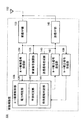
図1は、本発明の実施の形態1に係るマルチホップアドホックネットワークシステムを適用した通信システム100の構成を示すブロック図である。
【0029】
図1において、携帯電話機等の端末装置101及び106が移動局として互いの間で通信を行う場合について説明する。端末装置101及び106は、互いの間で通信を行う際に、その間に存在する他の端末装置102〜105のいずれかを中継局として利用することにより、基地局等を介さずに通信を行う。
【0030】
この場合、端末装置101及び106間において通信を行うための中継局として、端末装置102〜105のいずれかを選択する必要がある。通信システム100では、中継局として機能する構成を有する端末装置102〜105が、所定のタイミングごとに定期的にルート検索信号を送信する。このルート検索信号を受信した端末装置101は、当該ルート検索信号の送信元である端末装置102〜105のうち、いずれが中継局として利用可能であるか、又はより良い通信環境を提供し得るものであるかを判断するようになされている。
【0031】
因みに、端末装置101及び106の間にある複数の端末装置102〜105のうち、端末装置102及び103のみが、端末装置101との間で直接信号を送受信可能な範囲にある場合には、これら2つの端末装置102及び103から送信されるルート検索信号のみが端末装置101において受信されることとなり、この結果において、これらいずれかの端末装置102又は103と端末装置101との間で通信路が確立される。そして、端末装置102及び103は、その先にある端末装置104及び105から定期的に送信されるルート検索信号を受信することにより、当該端末装置102又は103と、端末装置104又は105との間で通信路が確立される。このように、通信システム100では、端末装置101及び106の間にある端末装置102〜105のいずれかが中継局として利用され、端末装置101及び106の通信が確立される。
【0032】
因みに、図1においては、互いに通信を行う端末装置101及び106の間に、中継局として機能する構成を有する端末装置が4つ存在する場合を示しているが、実際には端末装置101及び106の間には、さらに多くの端末装置が存在する場合、又は3つ以下の端末装置が存在する場合もあり得る。
【0033】
図2は、中継局装置として動作可能である構成を有する端末装置102の構成を有するブロック図である。なお、図1に示した端末装置103〜105も、端末装置102と同様の構成を有するものとする。
【0034】
図2において、端末装置102は、複数の素子アンテナ112−1〜112−nにおいて受信された信号をこれらの素子アンテナ112−1〜112−nに対応した受信RF(Radio Frequency)部113−1〜113−nに入力する。各受信RF部113−1〜113−nは、それぞれ入力された信号に対して、ダウンコンバート処理等の受信処理を施した後、指向性制御部115に供給する。
【0035】
指向性制御部115は、複数の受信RF部113−1〜113−nから供給された受信信号に対して、回線推定、最適ウェイトを用いた適応的指向性受信信号の生成等の処理を行う。
【0036】
指向性制御部115においてウェイト制御が行われた受信信号は、受信信号復調部116に供給され、ここで所定の復調処理が施される。
【0037】
また、送信信号生成部117は、送信用とする信号を変調した後、これを指向性制御部115に供給する。指向性制御部115は、送信信号生成部117から供給された信号を、ウェイト制御された複数の送信信号として送信RF部125−1〜125−nにそれぞれ供給する。
【0038】
送信RF部125−1〜125−nは、指向性制御部115から供給される各ウェイト制御された送信信号に対して、それぞれアップコンバート処理等を施した後、これを対応する素子アンテナ112−1〜112−nを介して送信する。かくして、端末装置102では、その指向性制御部115によるアダプティブアレイアンテナ技術により、信号を良好な送受信環境(指向性パターン)にて送受信することができる。すなわち、端末装置102等の端末装置では、アダプティブアレイアンテナと呼ばれる指向性の制御が可能なアンテナ装置を用い、2つの他の端末装置に対する指向性を、希望する方向に対して強く送受信できるビームを形成し、干渉となる方向に対しては弱く送受信できるヌルを形成するように調整し、通信環境を良好に保つようになされている。
【0039】
この端末装置102は、中継局として動作する場合には、受信RF部113−1〜113−nを介して受信された信号に基づいて、指向性制御部115において指向性制御した後、この受信された信号を、送信RF部125−1〜125−nを介して送信するようになされている。
【0040】
ここで、この中継局として利用可能である端末装置102には、ルート検索制御部118が設けられている。ルート検索制御部118は、送信電力値を電力情報として生成する電力情報生成部119と、端末装置102の環境における干渉状態を干渉情報として生成する干渉情報生成部120と、端末装置102の仰角の角度変動を表す仰角変動情報を生成する仰角変動情報生成部121とを有する。
【0041】
干渉情報生成部120は、指向性制御部115を介して供給された受信信号のSIR(Signal Interference Ratio)値や干渉電力量を干渉情報として生成する。また、仰角変動情報生成部121は、例えばジャイロ等の仰角測定手段を有しこの測定結果を、端末装置102の姿勢変化を表す仰角変動情報(姿勢変化情報)として生成する。この仰角変動情報は、本発明の特徴をなすものであり、その態様は種々のものが考えられる。詳細については後述する。
【0042】
ルート検索制御部118は、電力情報生成部119、干渉情報生成部120及び仰角変動情報生成部121において生成された各情報を、指向性制御部115に供給する。指向性制御部115は、ルート検索制御部118から供給されたこれらの各情報を送信信号に挿入して送信する。
【0043】
従って、図1について上述したように、端末装置102は、ルート検索制御部118において生成された電力情報、干渉情報及び仰角変動情報を、ルート検索用情報として定期的に送信する。
【0044】
このルート検索用情報を受信した端末装置101は、そのルート検索用情報に基づいて、端末装置102が中継局として利用可能な通信環境にあるか否かを判断する。この判断のタイミングとしては、その端末装置101が他の端末装置(例えば端末装置106)との間で通信を行うためのルート(中継局)を探索する場合、又は、中継局として機能することが可能な端末装置102又は103からの定期的なルート検索情報を受信する毎に行う等、そのタイミングとしては種々のタイミングを適用することができる。
【0045】
図3は、移動局装置として動作する端末装置101の構成を示すブロック図である。図3において、端末装置101は、素子アンテナ132において受信された信号を受信RF部133に入力する。受信RF部133は、入力された信号に対して、ダウンコンバート処理等の受信処理を施した後、ルート検索信号受信部134、受信信号復調部135及びルート確立信号受信部136にそれぞれ供給する。
【0046】
受信信号復調部134は、受信RF部133から供給された受信信号に対して、所定の復調処理を施す。ルート検索信号受信部134は、受信RF部133から供給された受信信号から、その受信信号に挿入されているルート検索用情報を抽出し、当該抽出された情報をルート検索制御部138に供給する。
【0047】
ルート検索制御部138は、受信信号から抽出されたルート検索用情報に含まれている電力情報と、受信信号の受信信号レベルに基づいて、その受信信号の送信元である端末装置102との間の通信状態を判定する。また、ルート検索制御部138は、受信信号から抽出されたルート検索用情報に含まれている干渉情報に基づいて、その受信信号の送信元である端末装置102の干渉状態を判定する。また、ルート検索制御部138は、受信信号から抽出されたルート検索用情報に含まれる仰角変動情報に基づいて、その受信信号の送信元である端末装置102の仰角変動レベルを判定する。
【0048】
ルート検索制御部138は、これらの判断結果に基づいて、このときの判断対象である端末装置102が中継局として利用可能であるか否かを判断する。すなわち、図4は、ルート検索制御部138による判定処理手順を示すフローチャートであり、ルート検索制御部138は、このとき受信したルート検索用情報に基づき、そのルート検索用情報の送信元である端末装置(例えば端末装置102)の電力状態及び干渉状態を判定する(ステップST101)。電力判定部139における判定結果として、端末装置101及び102の間の通信状態(電力状態)が良好であり、かつ、干渉判定部140における判定結果として、端末装置102の干渉状態が良好である場合には、その端末装置102を中継局候補として選択する。この選択結果は、仰角変動判定部141における判定結果と併せて、端末装置101の内部メモリ(図示せず)に格納される。
【0049】
このようにして、端末装置101のルート検索制御部138は、端末装置102が中継局候補とするか否かの判断を行った後、ステップST102に移って、その他の端末装置からのルート検索信号を受信したか否かを判断する。ここで、肯定結果が得られると、このことは、端末装置101との通信が可能な範囲に中継局として利用可能な構成を有する他の端末装置が存在することを意味しており、このときルート検索制御部138は上述のステップST101に戻って、新たな端末装置からのルート検索用情報に基づいて、その端末装置の電力状態及び干渉状態を判定し、当該判定結果に基づいて、その端末装置が中継局として利用可能な電力状態及び干渉状態であるか否かを判断する。
【0050】
このように、その他の端末装置から送信されたルート検索信号に基づいて、順次、当該その他の端末装置についても、中継局候補として選択するか否かを判断する。そして、ルート検索信号を受け取った全ての端末装置(例えば図1に示した端末装置102及び103)について、中継局候補とするか否かの選択結果と、各仰角変動判定結果とを求めた後、ルート検索制御部138はステップST103に移る。
【0051】
ステップST103において、ルート検索制御部138は、各中継局候補について、端末装置101のルート検索制御部138は、それらのうち、最も仰角変動の少ない端末装置を中継局として選択する。
【0052】
かくして、端末装置101のルート確立信号送信部142は、中継局として選択した端末装置(例えば端末装置102とする)に対して、ルート確立信号を送信し、このルート確立信号を受信した端末装置102は、そのルート確立信号に対する応答を端末装置101に返信することにより、送信元としての端末装置101及び中継局としての端末装置102の間において通信路(ルート)が確立される。
【0053】
このようにして、端末装置101及び102の間の通信路(ルート)が確立されると、これに続いて、このとき新たに中継局として選択及び確立された端末装置102が、上述の端末装置101の場合と同様にして、このとき最終的に確立しようとしている端末装置106との間にある他の端末装置104及び105のいずれかを中継局として選択する。
【0054】
以上説明した中継局の選択処理を繰り返しながら端末装置101及び106の間において、複数の端末装置(例えば端末装置102及び105)を中継局とした通信路(ルート)が確立される。これにより、端末装置101及び106は、互いに通信を行うことが可能となる。
【0055】
ここで、端末装置102〜105から送信されるルート検索用情報に含まれる仰角変動情報(姿勢変化情報)について説明する。この実施の形態の場合、端末装置102の仰角変動情報生成部121は、ジャイロ等の仰角測定手段を有し、この仰角測定手段によって測定された結果を、内部メモリ(図示せず)に格納する。仰角変動情報生成部121は、所定のタイミングごとに仰角測定結果を内部メモリ(図示せず)に格納して行くことにより、過去所定期間における仰角測定結果に基づいて、仰角の変動状態を検出する。この仰角変動状態としては、過去所定期間における仰角の変動量の最大値を変動状態として用いる。但し、仰角変動状態としては、変動量の最大値に限らず、過去所定期間における仰角測定結果の変動の周期等も考慮することが考えられる。この場合には、変動の周期が短く、変動量の大きさも予め定められた一定値以上となっている場合には、その端末装置の姿勢が頻繁に変動し、未来にわたって変動量が大きく変化することが予測されるものとして、変動量が大きい場合と等価として扱うこととなる。端末装置102では、このようにして得られた仰角変動情報を、定期的にブロードキャストしている。
【0056】
また、上述のルート検索制御部118の仰角変動情報生成部121では、ジャイロを用いて仰角測定を行うような、実測値に基づいた仰角変動情報の生成を行う場合について述べたが、本発明はこれに限らず、例えば、利用形態を限定して事前に設定するようにしてもよい。すなわち、仰角変動が小さい車載用の端末装置については、クラスAを仰角変動情報(姿勢変化情報)として設定し、また、鞄等によって持ち歩くタイプの端末装置については、クラスBを仰角変動情報(姿勢変化情報)として設定し、また、頻繁に通話に用いるタイプの端末装置については、クラスCを仰角変動情報(姿勢変化情報)として予め内部メモリ等に設定しておく。
【0057】
そして、端末装置101が、その端末装置を中継局として用いるか否かの判断を行う場合に、電力及び干渉の制約が緩い場合には、クラスA、クラスB及びクラスCの全てを利用可能であると判断し、これに対して、制約が厳しい場合には、クラスAから優先的に選択する。これにより、中継局として利用可能な端末装置102〜105において、ジャイロ等の複雑な構成を用いることなく、クラスを表す情報を記憶しておくだけでよく、その構成を一段と簡略化することができる。
【0058】
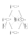
因みに、図5及び図6は、通信元(端末装置101)と通信先(端末装置106)との間に、中継局として機能する構成を有する端末装置102及び103がある場合の、通信路(ルート)の確立手順を説明する略線図である。
【0059】
図5において、端末装置102及び103は、それぞれ、所定のタイミング毎に、ルート検索用情報を配布(送信)する。このルート検索用情報を受信した端末装置101及び106は、そのルート検索用情報に基づいて、電力状態、干渉状態をそれぞれ判定するとともに、仰角変動情報に基づいて仰角変動量を判定する。
【0060】
そして、図6に示すように、端末装置101は、電力状態及び干渉状態が良好であることを条件に、仰角変動量が小さい端末装置102を中継局として選択する。これにより、端末装置106を相手に通信をしようとする端末装置101と、中継局として利用される端末装置102との間の通信路が確立される。すなわち、端末装置101は、端末装置102を中継局として選択して、マルチホップ接続を行う。
【0061】
この状態において、端末装置102は、通信先として指定された端末装置106に対して、通信要求を送信することにより、この端末装置102及び106間においても通信路が確立され、この結果、端末装置101及び106間において、端末装置102を中継局とした通信路が確立される。
【0062】
以上の構成において、通信システム100では、中継局として機能し得る端末装置102〜105のなかから、その仰角変動量の小さいものを選択する。中継局として選択された端末装置においては、その仰角変動量が小さいことにより、所望の指向性をその目標通りに利用することが可能となる。
【0063】
すなわち、通信システム100においては、中継局として利用される端末装置102〜105は、中継局として利用される限りにおいて、そのユーザの意図に関わらず選択されることとなる。
【0064】
このことは、中継局として利用される端末装置の姿勢は、常に一定となっているとは限らないことを意味している。従って、中継局を選択する端末装置(例えば端末装置101)は、中継局として選択可能な端末装置(例えば端末装置102及び103)のなかから、その仰角変動量の最も小さいものを選択する。これにより、実際に通信を行う際に、その中継局として選択された端末装置の姿勢が、意図した指向性が得られる姿勢となっている可能性が最も高いこととなる。
【0065】
従って、このような方法によって選択された中継局を介して通信を行うことにより、一段と良好な通信環境での通信を行うことができる。
【0066】
このように、本実施の形態の装置によれば、通信路(ルート)を検索する手順として、定期的なブロードキャストにより仰角変動量を、中継局として選択可能な端末装置から、その周囲の端末装置に配布することにより、ルート検索時に、仰角方向の変動量が小さな端末装置ほど優先度が高くなるように検索する。これにより、ビーム・ヌル形成を意図したとおりに実現できる端末が中継局の役割を果たすことで、通信システム100におけるリンクを空間的に分離する効果を十分に発揮させることができる。
【0067】
(実施の形態2)
図7は、本発明の実施の形態2に係るマルチホップアドホックネットワークシステムに用いられる、中継局装置として動作可能である端末装置202の構成を示すブロック図である。但し、図2に示した端末装置102と同一となる部分には図2と同一符号を付して示し、詳しい説明は省略する。
【0068】
図7に示す端末装置202は、ルート検索制御部118において、電力情報生成部119及び干渉情報生成部120を有しており、図2について上述した仰角変動情報生成部121を有していない点、及び、良好な指向性を確保する手段として指向性更新速度制御部205を有している点が、図2に示した端末装置102の構成と異なる。
【0069】
端末装置202は、ルート検索制御部118の電力情報生成部119において生成された電力情報と、干渉情報生成部120において生成された干渉情報とを定期的にブロードキャストしており、この情報に基づいて、端末装置101によって当該端末装置202が中継局として選択されると、ルート検索制御部118は、端末装置101から送信されたルート確立信号を受信信号から得ることにより、端末装置202が中継局として選択されたことを認識し、指向性更新速度制御部205によって、指向性制御部115でのアダプティブアレイアンテナ技術の指向性制御の更新速度を速くする。
【0070】
このように、端末装置202では、中継局として選択されると、アダプティブアレイアンテナの指向性の更新速度を速くすることにより、端末装置202の姿勢変化によって水平面内での指向性パターンが変化する速度に対して、指向性更新速度を追従させることができる。
【0071】
これにより、端末装置202の姿勢が変化して端末装置101との間の水平面内での指向性パターンが変化しても、指向性制御部115における指向性更新速度が速くなることにより、端末装置101及び端末装置202との間では、良好な通信環境を維持することができる。
【0072】
因みに、図8は、中継局として利用可能な端末装置(例えば端末装置102)のルート検索制御部118における指向性更新速度変更処理手順を示すフローチャートである。図8においてルート検索制御部118は、ステップST111において、選択結果を待ち受ける。そして、端末装置102を中継局として利用する旨を示すルート確立信号を受信すると、ルート検索制御部118は、ステップST112において肯定結果を得ることにより、ステップST113に移り、指向性更新速度制御部205に対して、指向性制御部115によるアダプティブアレイアンテナの指向性の更新速度(頻度)を高くする旨の制御信号を供給する。
【0073】
これにより、指向性更新速度制御部205は、指向性制御部115におけるアダプティブアレイアンテナの指向性更新速度の更新頻度を高くする。この結果、指向性制御部115では、端末装置102の姿勢が変化しても、端末装置101との間の良好な通信環境が得られる指向性制御を常に行うことができる。
【0074】
そして、ルート検索制御部118は、ステップST114に移り、中継局として選択された状態が解除されるのを待ち受ける。端末装置101とその通信相手である端末装置106(図1)との間の通信が完了すると、中継局として選択されている端末装置102の選択状態が端末装置101からの解除要求信号によって解除される。
【0075】
この結果、端末装置102のルート検索制御部118は、ステップST115において肯定結果を得、続くステップST116に移って、指向性更新速度を通常の状態に戻した後、上述のステップST111に戻って、新たな選択結果を待ち受けることとなる。
【0076】
図9は、中継局として利用される端末装置102の指向性制御による指向性パターンを示す略線図である。この図9に示すように、中継局として機能する端末装置102の傾きがある範囲内(i′)である場合には(図9(B))、その指向性は、端末装置101及び106に対して良好なパターンが形成されるのに対して、端末装置102の傾きが大きくなると(図9(C))、その指向性は端末装置101及び106に対して、通信を行うに十分ではなくなる。従って、この場合には、指向性更新速度が高められることにより、良好な指向性パターンが維持されることとなる。
【0077】
このように、本実施の形態の装置によれば、マルチホップによる通信路(ルート)を確立する場合、中継局として選択された端末装置(例えば端末装置102)において、アダプティブアレイアンテナの適応的指向性制御の更新頻度を高くすることにより、中継局として選択された端末装置102の姿勢が変化しても、当該端末装置102の指向性は、中継局として用いられる良好な指向性を維持することができる。従って、端末装置102のユーザが当該端末装置102が中継局として利用されていることの認識の有無に関わらず、その端末装置102を中継局として実用上十分な通信環境を維持しながら、利用することができる。
【0078】
因みに、図7について上述した端末装置102では、仰角変動情報生成部121(図2)を用いることに代えて、指向性更新速度制御部205により指向性更新速度を適応的制御する場合について述べたが、本発明はこれに限らず、例えば、図2について上述した仰角変動情報生成部121を併用し、「現在、中継局の役割を果たしている」という条件と、「仰角方向の変動量(例えばジャイロ等の仰角変動測定手段により測定した結果)が秒間数十°におよぶ」という条件との両方が成立した場合に、指向性更新速度を高くするようにしてもよい。このようにすれば、中継局として機能しているという条件だけで指向性更新速度を高くする場合に比べて、実際の仰角変動を考慮した制御を行うことができ、実際の状態に一段と適応した制御を行うことができる。従って、この場合には、中継局として機能している場合であっても、仰角変動量が大きくなっていない場合には、指向性更新速度は、高くならないことにより、消費電力を抑える効果もある。
【0079】
(実施の形態3)
図10は、本発明の実施の形態3に係るマルチホップアドホックネットワークシステムに用いられる、中継局装置として動作可能である端末装置302の構成を示すブロック図である。但し、図2に示した端末装置102と同一となる部分には図2と同一符号を付して示し、詳しい説明は省略する。
【0080】
図10に示す端末装置302は、仰角変動情報生成部121において生成された仰角変動情報に基づいて、指向性制御を行うか否かを判定する指向性適用判定部305を有している点が、図2に示した端末装置102の構成と異なる。
【0081】
端末装置302は、ルート検索制御部118の電力情報生成部119において生成された電力情報と、干渉情報生成部120において生成された干渉情報、仰角変動情報生成部121において生成された仰角変動情報とを、ルート検索用情報として定期的にブロードキャストしており、この情報に基づいて、端末装置101によって当該端末装置202が中継局として選択されると、ルート検索制御部118は、端末装置101から送信されたルート確立信号を受信信号から得ることにより、端末装置202が中継局として選択されたことを認識し、中継局として、端末装置101と106との中継を行う。
【0082】
この場合、指向性適用判定部305は、仰角変動情報生成部121から供給される仰角変動情報に基づいて、指向性制御部315の指向性制御を行うための指向性合成部317又は、指向性制御を行わず無指向性送信を行うための無指向性合成部316のいずれかを選択する。因みに、指向性制御部315は、切り換え可能な指向性合成部317及び無指向性合成部316を有する点を除けば、図1について上述した指向性制御部115と同様の構成を有するものとする。
【0083】
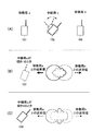
指向性合成部317が選択されると、当該指向性合成部317によって、アダプティブアレイアンテナのウェイト制御が行われ、各素子アンテナ113−1〜113−nに対して、適応的な重み付けを行うことにより、指向性パターンを端末装置101及び106との通信を行うために良好なパターンに制御する。この状態を図11(B)に示す。
【0084】
これに対して、無指向性合成部316が選択されると、当該無指向性合成部316によって、アダプティブアレイアンテナのウェイト制御が行われ、各素子アンテナ113−1〜113−nに対して、無指向性パターンが形成されるような重み付けを行うことにより、無指向性パターンを形成する。この状態を図11(C)に示す。
【0085】
このように、端末装置302では、中継局として選択されると、アダプティブアレイアンテナの指向性を端末装置101及び106との通信に良好なパターンとして適応的に形成する指向性制御、又は無指向性パターンを形成する無指向性制御のいずれかを、仰角変動情報に基づいて選択する。
【0086】
図12は、中継局として利用可能な端末装置(例えば端末装置302)における指向性適用制御処理手順を示すフローチャートである。図11において端末装置302は、ステップST121において、選択結果を待ち受ける。そして、端末装置302を中継局として利用する旨を示すルート確立信号を受信すると、端末装置302は、ステップST122において肯定結果を得ることにより、ステップST123に移り、ルート検索制御部118の仰角変動情報を指向性適用判定部305が取得する。この仰角変動情報としては、ジャイロ等の仰角変動測定手段による現在の仰角方向の変動量が用いられる。
【0087】
そして、ステップST124において、指向性適用判定部305は、取得した仰角変動情報に基づいて、指向性制御部115におけるアダプティブアレイアンテナ制御として、端末装置101及び106との通信に良好なパターンを適応的に形成する指向性制御(指向性合成部317)、又は無指向性パターンを形成する無指向性制御(無指向性合成部316)のいずれかを選択する。
【0088】
指向性制御が選択されると、ステップST125において、指向性制御が実行され、指向性合成部317によって、送受信信号に対して、最適な指向性パターンが形成されるようなウェイト制御がなされることにより、図11(B)に示したように、このとき中継局として機能する端末装置302において、その通信元である端末装置101と通信先である端末装置106に対して、良好な指向性パターンが形成される。
【0089】
この結果、端末装置302の仰角変動量が少ない場合には、アンテナの指向性を適応的に制御することにより、このときの通信元である端末装置101と、通信先である端末装置106とに対して、良好な指向性パターンを形成することにより、端末装置101及び106の間において、良好な通信環境で中継局として機能することが可能となる。
【0090】
これに対して、ステップST124において無指向性制御が選択されると、ステップST126において、無指向性制御が実行され、無指向性合成部316によって、送受信信号に対し、無指向性パターンが形成されるようなウェイト制御がなされる。
【0091】
この結果、端末装置302の仰角変動量が大きい場合には、アンテナを無指向性とすることにより、極端に通信環境が劣化する状態を未然に防止することができる。
【0092】
そして、ルート検索制御部118は、ステップST127に移り、中継局として選択された状態が解除されるのを待ち受ける。端末装置101とその通信相手である端末装置106(図1)との間の通信が完了すると、中継局として選択されている端末装置302の選択状態が端末装置101からの解除要求信号によって解除される。
【0093】
この結果、端末装置302のルート検索制御部118は、ステップST127において肯定結果を得、上述のステップST121に戻って、新たな選択結果を待ち受けることとなる。かくして、この処理手順によれば、「現在、中継局の役割を果たしている」という条件と、「現在は仰角方向に大きく変動している(ジャイロ等によって測定)」という条件との両者が満たされた場合に、無指向性制御に切り換えることにより、中継局として機能するための水平面での指向性パターンが極端にはずれることを防止することができる。
【0094】
このように、本実施の形態の装置によれば、マルチホップによる通信路(ルート)を確立する場合、中継局として選択された端末装置(例えば端末装置302)において、中継局としての役割を果たしている場合に、仰角方向の大きな変化があれば、指向性送受信から無指向性送受信に切り換えることにより、マルチホップにおけるリンクで無理な指向性形成を試みることによって干渉が増大するという不都合を防止することができる。
【0095】
(他の実施の形態)
なお、上述の実施の形態においては、中継局として利用可能な構成を有する端末装置102、202及び302が中継局として動作する場合について述べたが、本発明はこれに限らず、これらの端末装置102、202及び302が、端末装置101又は106のように通信の当事者となるように動作することも可能である。
【0096】
また、上述の実施の形態においては、中継局として利用可能な端末装置102〜105、202及び302が、定期的にルート検索用情報をブロードキャストする場合について述べたが、本発明はこれに限らず、通信を行おうとする端末装置101から所定の信号を送信した場合にのみ、この信号を受け取った端末装置が、ルート検索用情報を送信するようにしてもよい。
【0097】
【発明の効果】
以上説明したように、本発明によれば、中継局として利用可能な端末装置の仰角変動(姿勢変化)に基づいて、当該中継局を利用するか否かを決定することにより、仰角変動による当該端末装置の水平面での指向性パターンの劣化が少ない中継局を選択することができる。これにより、中継局として選択された端末装置において、通信の当事者である2つの端末装置に対して、それぞれのリンクを空間的に分離することができ、良好な通信環境での中継を提供することができる。
【図面の簡単な説明】
【図1】本発明の実施の形態1に係る通信システムの構成を示すブロック図
【図2】実施の形態1に係る中継局として利用可能な端末装置の構成を示すブロック図
【図3】実施の形態1に係る送信元である端末装置の構成を示すブロック図
【図4】本発明の実施の形態1に係る端末装置の中継局の選択可否の判定処理手順を示すフローチャート
【図5】実施の形態1に係る通信システムの中継局の選択処理の説明に供する略線図
【図6】実施の形態1に係る通信システムの中継局の選択処理の説明に供する略線図
【図7】本発明の実施の形態2に係る中継局として利用可能な端末装置の構成を示すブロック図
【図8】実施の形態2に係る中継局として利用可能な端末装置の動作を説明するためのフローチャート
【図9】実施の形態2に係る中継局として利用可能な端末装置の指向性パターンの説明に供する略線図
【図10】本発明の実施の形態3に係る中継局として利用可能な端末装置の構成を示すブロック図
【図11】実施の形態3に係る中継局として利用可能な端末装置の指向性パターンの説明に供する略線図
【図12】実施の形態3に係る中継局として利用可能な端末装置の動作を説明するためのフローチャート
【符号の説明】
100 通信システム
101、102、103、104、105、106、202、302 端末装置
112−1〜112−n 素子アンテナ
113−1〜113−n、133 受信RF部
115 指向性制御部
116、135 受信信号復調部
117、143 送信信号生成部
118 ルート検索制御部
119 電力情報生成部
120 干渉情報生成部
121 仰角変動情報生成部
125−1〜125−n、145 送信RF部
134 ルート検索信号受信部
138 ルート検索制御部
139 電力判定部
140 干渉判定部
141 仰角変動判定部
142 ルート確立信号送信部
205 指向性更新速度制御部
305 指向性適用判定部
316 無指向性合成部
317 指向性合成部[0001]
BACKGROUND OF THE INVENTION
The present invention Moving body Communications system, Mobile station as well as Moving body The present invention relates to a relay station selection method of a communication system.
[0002]
[Prior art]
Conventionally, a system called a so-called multi-hop ad hoc network that uses another terminal device as a relay station when communicating between two terminal devices has been considered.
[0003]
In this system, as described in “2001 RCS Technical Report RCS2001-19,“ Performance Evaluation of Multihop Ad Hoc Network Considering Adaptive Antenna ””, two terminal devices are connected to other terminals. Communication is performed using the device as a relay station. A terminal device used as a relay station uses an antenna device called an adaptive array antenna that can control directivity, forms a beam that can transmit and receive the directivity with respect to two terminal devices strongly in a desired direction, and interferes. It is intended to maintain a good communication environment by adjusting so as to form a null that can be transmitted and received weakly in the direction.
[0004]
[Problems to be solved by the invention]
However, in a terminal device used as a relay station of a conventionally considered multi-hop ad hoc network system, it is necessary to form a beam and a null as intended when performing antenna directivity control using an adaptive array antenna. .
[0005]
The formation of the beam and the null is that the intended beam and the null can be formed by focusing only on the horizontal plane as described in “2001 RCS Technical Report RCS2001-18”. Based on this.
[0006]
Therefore, when the terminal device used as a relay station is kept at a constant angle (antenna is vertical), the intended directivity can be obtained, but when the elevation angle of the terminal device fluctuates. Since the angle of the antenna also fluctuates, it is difficult to form an intended beam and null, and it is difficult to compensate for mutual coupling between terminal devices in an arbitrary elevation direction.
[0007]
In particular, a user of a terminal device such as a mobile phone used as a relay station is irrelevant to the party involved in the communication. For example, when the user is moving with a mobile phone in a bag, The telephone is not always kept in the intended elevation direction.
[0008]
Therefore, the conventional multi-hop ad hoc network system has a problem that it is difficult to always maintain a good communication environment even if a terminal device using an adaptive array antenna (adaptive antenna) is used as a relay station.
[0009]
The present invention has been made in view of such points, and has a multi-hop ad hoc network system configuration that can provide a better communication environment. Moving body Communications system, Mobile station as well as Moving body It is an object of the present invention to provide a relay station selection method for a communication system.
[0010]
[Means for Solving the Problems]
The communication system according to the present invention includes a third terminal device operable as a relay station that delivers a signal from the first terminal device to the second terminal device, and the third terminal device supplied from the third terminal device. And a first terminal device that determines whether or not to use the third terminal device as a relay station based on posture change information representing a posture change of the terminal device.
[0011]
According to this configuration, by determining whether or not to use as a relay station based on the attitude change information of the terminal device, a terminal capable of ensuring good directivity can be used as the relay station. .
[0012]
The communication system according to the present invention employs a configuration in which, in the above configuration, the third terminal apparatus includes a measuring unit that measures its own elevation angle variation information as the posture change information.
[0013]
According to this configuration, it is possible to make a determination based on actual elevation angle variation by determining whether or not use as a relay station is possible based on the measurement result of the elevation angle variation amount of the terminal device.
[0014]
The communication system according to the present invention employs a configuration in which, in the above configuration, the third terminal device holds its own posture change information in advance.
[0015]
According to this configuration, the terminal devices are classified in advance into terminal devices with a large change in posture or terminal devices with a small amount of posture, and posture change information corresponding to the classified terminal devices is held in advance in each terminal device. Thus, it is not necessary to provide the terminal device with an elevation angle variation measuring means having a complicated configuration such as a gyro.
[0016]
The terminal device of the present invention can use the other terminal device as a relay station based on attitude change information transmitted from another terminal device operable as a relay station and representing the attitude change of the other terminal device. A configuration is adopted that includes a determination unit that determines whether or not there is, and a control unit that uses the other terminal device as a relay station based on a determination result of the determination unit.
[0017]
According to this configuration, by determining whether or not to use as a relay station based on the attitude change information of the terminal device that can operate as the relay station, a terminal that can ensure good directivity is determined as the relay station. Can be used as
[0018]
The terminal device according to the present invention serves as a relay station based on posture change information transmitting means for transmitting posture change information representing its own posture change and a signal received from another terminal device and requesting an operation as a relay station. And a control means for executing the above operation.
[0019]
According to this configuration, it is possible to cause another terminal device to determine whether or not it can be used as a relay station by transmitting its own attitude change information.
[0020]
In the terminal device according to the present invention, in the configuration described above, the posture change information transmitting unit includes a measuring unit that measures an elevation angle variation of the terminal device itself, and generates the posture change information based on a measurement result of the measuring unit. The structure to do is taken.
[0021]
According to this configuration, it is possible to make a determination based on the actual elevation angle variation by determining whether or not the relay station can be used based on the measurement result of the own elevation angle variation amount.
[0022]
The terminal device according to the present invention employs a configuration in which, in the above-described configuration, the posture change information transmitting unit holds posture change information of the terminal device itself and transmits the held posture change information.
[0023]
According to this configuration, the terminal device is pre-classified into a terminal device with a large attitude change or a terminal apparatus with a small attitude, and the attitude change information corresponding to the classified terminal device is held in advance in each terminal device, There is no need to provide a posture change measuring means having a complicated configuration such as a gyro in the terminal device.
[0024]
The relay station selection method for a communication system according to the present invention includes a third terminal device operable as a relay station that delivers a signal from the first terminal device to the second terminal device. Whether or not to transmit attitude change information representing an attitude change to the first terminal apparatus and to use the third terminal apparatus as a relay station based on the attitude change information transmitted from the third terminal apparatus Is determined by the first terminal device, and based on the determination result, the third terminal device is used as a relay station.
[0025]
According to this method, a terminal capable of ensuring good directivity can be used as a relay station by determining whether to use as a relay station based on the attitude change information of the terminal device. .
[0026]
DETAILED DESCRIPTION OF THE INVENTION
The essence of the present invention is that when selecting a relay station, by determining whether or not the relay device can be selected based on posture change information representing posture change (elevation angle variation) of a terminal device having a configuration operable as a relay station, It is possible to select a relay station based on whether or not the directivity pattern on the horizontal plane is easily deviated from a desired pattern.
[0027]
Hereinafter, embodiments of the present invention will be described in detail with reference to the drawings.
[0028]
(Embodiment 1)
FIG. 1 is a block diagram showing a configuration of a
[0029]
In FIG. 1, a case where
[0030]
In this case, it is necessary to select one of the
[0031]
Incidentally, when only the
[0032]
Incidentally, FIG. 1 shows a case where there are four terminal devices having a configuration functioning as a relay station between the
[0033]
FIG. 2 is a block diagram having a configuration of
[0034]
In FIG. 2, the
[0035]
The
[0036]
The reception signal subjected to weight control in the
[0037]
In addition, the transmission
[0038]
The transmission RF units 125-1 to 125-n perform up-conversion processing and the like on the respective weight-controlled transmission signals supplied from the
[0039]
When this
[0040]
Here, the route
[0041]
The interference
[0042]
The route
[0043]
Therefore, as described above with reference to FIG. 1, the
[0044]
The
[0045]
FIG. 3 is a block diagram showing a configuration of
[0046]
The reception
[0047]
Based on the power information included in the route search information extracted from the received signal and the received signal level of the received signal, the route
[0048]
Based on these determination results, the route
[0049]
In this way, the route
[0050]
Thus, based on the route search signal transmitted from the other terminal device, it is sequentially determined whether or not the other terminal device is also selected as a relay station candidate. After obtaining the selection results as to whether or not to be relay station candidates and the determination results of each elevation angle variation for all terminal devices (for example, the
[0051]
In step ST103, the route
[0052]
Thus, the route establishment
[0053]
When the communication path (route) between the
[0054]
While repeating the relay station selection process described above, a communication path (route) is established between the
[0055]
Here, the elevation angle variation information (posture change information) included in the route search information transmitted from the
[0056]
In addition, the elevation angle variation
[0057]
When the
[0058]
Incidentally, FIGS. 5 and 6 show communication paths (
[0059]
In FIG. 5, each of the
[0060]
Then, as illustrated in FIG. 6, the
[0061]
In this state, the
[0062]
In the above configuration, the
[0063]
That is, in the
[0064]
This means that the attitude of the terminal device used as a relay station is not always constant. Therefore, the terminal device (for example, the terminal device 101) that selects the relay station selects the terminal device having the smallest elevation angle variation amount from the terminal devices (for example, the
[0065]
Therefore, communication can be performed in a better communication environment by performing communication through the relay station selected by such a method.
[0066]
As described above, according to the apparatus of the present embodiment, as a procedure for searching for a communication path (route), a terminal apparatus in the vicinity thereof can be selected from a terminal apparatus that can select an elevation angle variation amount as a relay station by periodic broadcast. When the route is searched, the terminal device with a smaller variation in the elevation angle direction is searched so that the priority is higher. As a result, a terminal that can realize beam / null formation as intended serves as a relay station, so that the effect of spatially separating links in the
[0067]
(Embodiment 2)
FIG. 7 is a block diagram showing a configuration of
[0068]
7 includes a power
[0069]
The
[0070]
As described above, when the
[0071]
As a result, even if the orientation of the
[0072]
Incidentally, FIG. 8 is a flowchart showing a directivity update rate change processing procedure in the route
[0073]
Thereby, the directivity update
[0074]
Then, the route
[0075]
As a result, the route
[0076]
FIG. 9 is a schematic diagram illustrating a directivity pattern by directivity control of the
[0077]
Thus, according to the apparatus of the present embodiment, when establishing a multi-hop communication path (route), the adaptive orientation of the adaptive array antenna in the terminal apparatus (for example, terminal apparatus 102) selected as the relay station. Even if the attitude of the
[0078]
Incidentally, in the
[0079]
(Embodiment 3)
FIG. 10 is a block diagram showing a configuration of
[0080]
The
[0081]
The
[0082]
In this case, the directivity
[0083]
When the
[0084]
On the other hand, when the
[0085]
As described above, in the
[0086]
FIG. 12 is a flowchart illustrating a directivity application control processing procedure in a terminal device (for example, the terminal device 302) that can be used as a relay station. In FIG. 11, the
[0087]
In step ST124, the directivity
[0088]
When directivity control is selected, directivity control is executed in step ST125, and weight control is performed by the
[0089]
As a result, when the amount of change in the elevation angle of the
[0090]
On the other hand, when omnidirectional control is selected in step ST124, omnidirectional control is executed in step ST126, and the
[0091]
As a result, when the amount of elevation angle fluctuation of the
[0092]
Then, the route
[0093]
As a result, the route
[0094]
As described above, according to the apparatus of the present embodiment, when establishing a multi-hop communication path (route), the terminal apparatus selected as the relay station (for example, the terminal apparatus 302) serves as a relay station. If there is a significant change in the elevation angle direction, switching from directional transmission / reception to omnidirectional transmission / reception prevents the inconvenience of increased interference by attempting to create excessive directivity on multi-hop links. Can do.
[0095]
(Other embodiments)
In the above-described embodiment, the case has been described in which
[0096]
In the above-described embodiment, the case has been described in which
[0097]
【The invention's effect】
As described above, according to the present invention, by determining whether to use the relay station based on the elevation angle fluctuation (attitude change) of the terminal device that can be used as a relay station, It is possible to select a relay station with little degradation of the directivity pattern on the horizontal plane of the terminal device. Thereby, in the terminal device selected as the relay station, the respective links can be spatially separated from the two terminal devices that are parties to communication, and relaying in a good communication environment is provided. Can do.
[Brief description of the drawings]
FIG. 1 is a block diagram showing a configuration of a communication system according to
FIG. 2 is a block diagram showing a configuration of a terminal apparatus that can be used as a relay station according to the first embodiment.
FIG. 3 is a block diagram showing a configuration of a terminal device that is a transmission source according to
FIG. 4 is a flowchart showing a determination process procedure of whether or not a relay station can be selected by the terminal apparatus according to
FIG. 5 is a schematic diagram for explaining relay station selection processing of the communication system according to the first embodiment;
6 is a schematic diagram for explaining selection processing of a relay station in the communication system according to
FIG. 7 is a block diagram showing a configuration of a terminal apparatus that can be used as a relay station according to Embodiment 2 of the present invention.
FIG. 8 is a flowchart for explaining the operation of a terminal apparatus that can be used as a relay station according to Embodiment 2;
FIG. 9 is a schematic diagram for explaining a directivity pattern of a terminal device that can be used as a relay station according to the second embodiment;
FIG. 10 is a block diagram showing a configuration of a terminal apparatus that can be used as a relay station according to Embodiment 3 of the present invention.
11 is a schematic diagram for explaining a directivity pattern of a terminal device that can be used as a relay station according to Embodiment 3. FIG.
FIG. 12 is a flowchart for explaining the operation of a terminal apparatus that can be used as a relay station according to Embodiment 3;
[Explanation of symbols]
100 communication system
101, 102, 103, 104, 105, 106, 202, 302 Terminal device
112-1 to 112-n element antenna
113-1 to 113-n, 133 reception RF section
115 Directivity control unit
116, 135 Received signal demodulator
117, 143 Transmission signal generator
118 Route Search Control Unit
119 Power information generation unit
120 Interference information generator
121 Elevation angle fluctuation information generator
125-1 to 125-n, 145 Transmitting RF unit
134 Route Search Signal Receiver
138 Route search control unit
139 Power determination unit
140 Interference determination unit
141 Elevation angle variation determination unit
142 Route establishment signal transmitter
205 Directional update rate control unit
305 Directivity application determination unit
316 Omnidirectional synthesis unit
317 Directional synthesis unit
Claims (4)
前記複数の第3の移動局から送信された前記仰角変動情報と前記複数の第3の移動局との間の通信状態及び干渉状態とを取得する取得手段を具備し、少なくとも前記通信状態及び前記干渉状態に基づいて、前記複数の第3の移動局から前記中継局として利用可能な候補を選定し、前記候補から前記仰角変動が最も少ない前記第3の移動局を前記中継局として選定する前記第1の移動局と、
を具備することを特徴とする移動体通信システム。An antenna that can operate as a relay station that delivers a signal from the first mobile station to the second mobile station, and that can control the directivity of the antenna, and detects a fluctuation state of its elevation angle at every predetermined timing. Measuring means for measuring elevation angle variation information, and a plurality of third mobile stations for transmitting the measured elevation angle variation information to the first mobile station,
An acquisition unit configured to acquire a communication state and an interference state between the elevation angle variation information transmitted from the plurality of third mobile stations and the plurality of third mobile stations; and at least the communication state and the Based on the interference state, a candidate usable as the relay station is selected from the plurality of third mobile stations, and the third mobile station with the smallest elevation angle variation is selected as the relay station from the candidates. A first mobile station;
A mobile communication system comprising:
前記他の移動局から送信された前記仰角変動情報と前記他の移動局との間の通信状態及び干渉状態とを取得する取得手段を具備し、少なくとも前記通信状態及び前記干渉状態に基づいて、複数の前記他の移動局から前記中継局として利用可能な候補を選定し、前記候補から前記仰角変動が最も少ない前記他の移動局を前記中継局として選定することを特徴とする移動局。It is a mobile station that uses another mobile station as a relay station, which has a fixed antenna whose directionality can be controlled and a measuring means that detects the fluctuation state of its own elevation angle at every predetermined timing and measures elevation angle fluctuation information. And
Comprising an acquisition means for acquiring a communication state and an interference state between the elevation angle variation information transmitted from the other mobile station and the other mobile station, and based on at least the communication state and the interference state; A mobile station characterized in that a candidate usable as the relay station is selected from a plurality of other mobile stations, and the other mobile station having the smallest elevation angle variation is selected from the candidates as the relay station.
固定で指向性を制御可能なアンテナと、
所定タイミングごとに自身の仰角の変動状態を検出して仰角変動情報を測定する測定手段と、
前記測定した仰角変動情報を他の移動局へ送信する送信手段と、
前記他の移動局において前記仰角変動情報を送信した自局及び自局と同等な移動局の中から、通信状態及び干渉状態に基づいて自局が中継局候補に選定され、且つ、前記中継局候補の中で前記仰角の変動が最も少ないときに、前記他の移動局が送信する中継局としての動作を要請する信号を受信する受信手段と、
前記要請信号を受信して中継局として動作し、且つ、前記仰角変動が所定量以上のときに、前記アンテナの指向性パタンの更新速度を高める指向性更新速度制御手段と、
を具備することを特徴とする移動局。A mobile station operable as a relay station,
An antenna that can be fixed and controllable directivity;
Measuring means for measuring the elevation angle fluctuation information by detecting the fluctuation state of its own elevation angle at each predetermined timing;
Transmitting means for transmitting the measured elevation angle variation information to another mobile station;
The local station is selected as a relay station candidate based on a communication state and an interference state from the local station that has transmitted the elevation angle variation information in the other mobile station and a mobile station equivalent to the local station, and the relay station Receiving means for receiving a signal requesting an operation as a relay station transmitted by the other mobile station when the variation in the elevation angle is the least among candidates ;
Directivity update rate control means for receiving the request signal, operating as a relay station , and increasing the update rate of the directivity pattern of the antenna when the elevation angle variation is a predetermined amount or more;
A mobile station characterized by comprising:
各第3の移動局は、所定タイミングごとに自身の仰角の変動状態を検出して仰角変動情報を測定し、前記測定した仰角変動情報を前記第1の移動局へ送信し、
前記第1の移動局は、前記複数の第3の移動局から送信された前記仰角変動情報と前記複数の第3の移動局との間の通信状態及び干渉状態とを取得し、少なくとも前記通信状態及び前記干渉状態に基づいて、複数の前記複数の第3の移動局から前記中継局として利用可能な候補を選定し、前記候補から前記仰角変動が最も少ない前記第3の移動局を前記中継局として選定する、
ことを特徴とする中継局選択方法。As a relay station that includes a first mobile station, a second mobile station, and a fixed antenna whose directionality can be controlled, and that delivers a signal from the first mobile station to the second mobile station A relay station selection method of a communication system comprising a plurality of operable third mobile stations,
Each third mobile station detects the fluctuation state of its own elevation angle at every predetermined timing, measures elevation angle fluctuation information, and transmits the measured elevation angle fluctuation information to the first mobile station,
The first mobile station acquires a communication state and an interference state between the elevation angle variation information transmitted from the plurality of third mobile stations and the plurality of third mobile stations, and at least the communication Based on the state and the interference state, a candidate that can be used as the relay station is selected from the plurality of third mobile stations, and the third mobile station with the smallest elevation angle variation is selected from the candidates as the relay station. Select as a station,
A relay station selection method characterized by the above.
Priority Applications (1)
| Application Number | Priority Date | Filing Date | Title |
|---|---|---|---|
| JP2002186207A JP4197408B2 (en) | 2002-06-26 | 2002-06-26 | COMMUNICATION SYSTEM, TERMINAL DEVICE, AND RELAY STATION SELECTION METHOD FOR COMMUNICATION SYSTEM |
Applications Claiming Priority (1)
| Application Number | Priority Date | Filing Date | Title |
|---|---|---|---|
| JP2002186207A JP4197408B2 (en) | 2002-06-26 | 2002-06-26 | COMMUNICATION SYSTEM, TERMINAL DEVICE, AND RELAY STATION SELECTION METHOD FOR COMMUNICATION SYSTEM |
Publications (2)
| Publication Number | Publication Date |
|---|---|
| JP2004032391A JP2004032391A (en) | 2004-01-29 |
| JP4197408B2 true JP4197408B2 (en) | 2008-12-17 |
Family
ID=31181618
Family Applications (1)
| Application Number | Title | Priority Date | Filing Date |
|---|---|---|---|
| JP2002186207A Expired - Lifetime JP4197408B2 (en) | 2002-06-26 | 2002-06-26 | COMMUNICATION SYSTEM, TERMINAL DEVICE, AND RELAY STATION SELECTION METHOD FOR COMMUNICATION SYSTEM |
Country Status (1)
| Country | Link |
|---|---|
| JP (1) | JP4197408B2 (en) |
Families Citing this family (14)
| Publication number | Priority date | Publication date | Assignee | Title |
|---|---|---|---|---|
| JP4539361B2 (en) * | 2005-02-16 | 2010-09-08 | アイシン精機株式会社 | Mobile communication device |
| EP2247146B1 (en) | 2005-12-14 | 2011-11-16 | Research In Motion Limited | Method and apparatus for user equipment directed radio resource control in a UMTS network |
| ES2353609T3 (en) | 2006-05-17 | 2011-03-03 | Research In Motion Limited | METHOD AND SYSTEM FOR INDICATION OF SIGNALING CONNECTION RELEASE IN A UMTS NETWORK. |
| JP5067085B2 (en) * | 2007-09-12 | 2012-11-07 | 沖電気工業株式会社 | Wireless communication device |
| JP4966161B2 (en) * | 2007-10-30 | 2012-07-04 | 日本無線株式会社 | In-vehicle packet information transmitter |
| ES2385415T3 (en) | 2007-11-13 | 2012-07-24 | Research In Motion Limited | Method and apparatus for state / mode transition |
| JP5280082B2 (en) * | 2008-03-28 | 2013-09-04 | 京セラ株式会社 | Portable wireless terminal device |
| JP5052474B2 (en) * | 2008-10-03 | 2012-10-17 | 株式会社東芝 | Repeater device |
| KR101299277B1 (en) | 2008-11-10 | 2013-08-23 | 리서치 인 모션 리미티드 | Method and apparatus of transition to a battery efficient state or configuration by indicating end of data transmission in long term evolution |
| MX2012005873A (en) | 2009-11-23 | 2012-11-30 | Research In Motion Ltd | Method and apparatus for state/mode transitioning. |
| AU2010321205B2 (en) | 2009-11-23 | 2014-09-04 | Blackberry Limited | State or mode transition triggering based on SRI message transmission |
| MX2012005871A (en) | 2009-11-23 | 2012-11-30 | Research In Motion Ltd | Method and apparatus for state/mode transitioning. |
| US8983532B2 (en) | 2009-12-30 | 2015-03-17 | Blackberry Limited | Method and system for a wireless communication device to adopt varied functionalities based on different communication systems by specific protocol messages |
| US9049657B2 (en) | 2011-11-11 | 2015-06-02 | Blackberry Limited | System and method of user equipment state transition |
-
2002
- 2002-06-26 JP JP2002186207A patent/JP4197408B2/en not_active Expired - Lifetime
Also Published As
| Publication number | Publication date |
|---|---|
| JP2004032391A (en) | 2004-01-29 |
Similar Documents
| Publication | Publication Date | Title |
|---|---|---|
| JP4197408B2 (en) | COMMUNICATION SYSTEM, TERMINAL DEVICE, AND RELAY STATION SELECTION METHOD FOR COMMUNICATION SYSTEM | |
| US8184601B2 (en) | Method for radio communication in a wireless local area network wireless local area network and transceiving device | |
| US7224954B2 (en) | Method and device for communicating via an ad-hoc wireless network | |
| US6975614B2 (en) | Intelligent communication node object beacon framework in a mobile ad hoc network | |
| US6763013B2 (en) | Intelligent communication node object beacon framework including neighbor discovery in a mobile ad hoc network | |
| KR960019852A (en) | Transceiver for communication using directional antenna | |
| JP4228342B2 (en) | Wireless transmission device for wireless network, route control method, and route control program | |
| JP2002368789A (en) | Method and system for routing message | |
| EP1220475A2 (en) | Mobile communication terminal apparatus with antenna array | |
| JP4726306B2 (en) | Wireless communication system, mobile terminal station and direction determination method | |
| JP2011130126A (en) | Control device, relay device, control method thereof, and program | |
| US7515940B2 (en) | Node dependent wireless transmit antenna selection technique | |
| JPWO2005002087A1 (en) | Communications system | |
| JP3899045B2 (en) | Wireless network control method and control apparatus | |
| JP3445549B2 (en) | Routing method and router device for wireless network | |
| JP2018142925A (en) | Communication device, base station device, terminal device, communication system, communication method, and program | |
| JP3920615B2 (en) | Routing method and router apparatus for wireless network | |
| JP3805701B2 (en) | Routing method and router apparatus for wireless network | |
| US20180199326A1 (en) | Real time adaptation of a mobile repeater antenna pattern | |
| Choudhury et al. | Mac-layer capture: A problem in wireless mesh networks using beamforming antennas | |
| JP2002262328A (en) | Mobile communication terminal | |
| JP7116203B2 (en) | BASE STATION DEVICE, COMMUNICATION SYSTEM, AND PROGRAM | |
| EP2239867A1 (en) | User terminal device and network accessing method used for it | |
| JP3936328B2 (en) | Wireless network routing method and wireless communication system | |
| JP2003115851A (en) | Method and device for controlling wireless network |
Legal Events
| Date | Code | Title | Description |
|---|---|---|---|
| A621 | Written request for application examination |
Free format text: JAPANESE INTERMEDIATE CODE: A621 Effective date: 20050303 |
|
| A977 | Report on retrieval |
Free format text: JAPANESE INTERMEDIATE CODE: A971007 Effective date: 20070410 |
|
| A131 | Notification of reasons for refusal |
Free format text: JAPANESE INTERMEDIATE CODE: A131 Effective date: 20070417 |
|
| A521 | Request for written amendment filed |
Free format text: JAPANESE INTERMEDIATE CODE: A523 Effective date: 20070615 |
|
| A131 | Notification of reasons for refusal |
Free format text: JAPANESE INTERMEDIATE CODE: A131 Effective date: 20070821 |
|
| A521 | Request for written amendment filed |
Free format text: JAPANESE INTERMEDIATE CODE: A523 Effective date: 20071018 |
|
| A131 | Notification of reasons for refusal |
Free format text: JAPANESE INTERMEDIATE CODE: A131 Effective date: 20080708 |
|
| A521 | Request for written amendment filed |
Free format text: JAPANESE INTERMEDIATE CODE: A523 Effective date: 20080806 |
|
| TRDD | Decision of grant or rejection written | ||
| A01 | Written decision to grant a patent or to grant a registration (utility model) |
Free format text: JAPANESE INTERMEDIATE CODE: A01 Effective date: 20080902 |
|
| A01 | Written decision to grant a patent or to grant a registration (utility model) |
Free format text: JAPANESE INTERMEDIATE CODE: A01 |
|
| A61 | First payment of annual fees (during grant procedure) |
Free format text: JAPANESE INTERMEDIATE CODE: A61 Effective date: 20080926 |
|
| FPAY | Renewal fee payment (event date is renewal date of database) |
Free format text: PAYMENT UNTIL: 20111010 Year of fee payment: 3 |
|
| R150 | Certificate of patent or registration of utility model |
Ref document number: 4197408 Country of ref document: JP Free format text: JAPANESE INTERMEDIATE CODE: R150 Free format text: JAPANESE INTERMEDIATE CODE: R150 |
|
| FPAY | Renewal fee payment (event date is renewal date of database) |
Free format text: PAYMENT UNTIL: 20121010 Year of fee payment: 4 |
|
| FPAY | Renewal fee payment (event date is renewal date of database) |
Free format text: PAYMENT UNTIL: 20131010 Year of fee payment: 5 |
|
| S111 | Request for change of ownership or part of ownership |
Free format text: JAPANESE INTERMEDIATE CODE: R313113 |
|
| R350 | Written notification of registration of transfer |
Free format text: JAPANESE INTERMEDIATE CODE: R350 |
|
| EXPY | Cancellation because of completion of term |