JP4191292B2 - Hollow material manufacturing method - Google Patents
Hollow material manufacturing method Download PDFInfo
- Publication number
- JP4191292B2 JP4191292B2 JP26479998A JP26479998A JP4191292B2 JP 4191292 B2 JP4191292 B2 JP 4191292B2 JP 26479998 A JP26479998 A JP 26479998A JP 26479998 A JP26479998 A JP 26479998A JP 4191292 B2 JP4191292 B2 JP 4191292B2
- Authority
- JP
- Japan
- Prior art keywords
- friction stir
- hollow
- long
- roller
- stir welding
- Prior art date
- Legal status (The legal status is an assumption and is not a legal conclusion. Google has not performed a legal analysis and makes no representation as to the accuracy of the status listed.)
- Expired - Fee Related
Links
Images


Classifications
-
- B—PERFORMING OPERATIONS; TRANSPORTING
- B23—MACHINE TOOLS; METAL-WORKING NOT OTHERWISE PROVIDED FOR
- B23K—SOLDERING OR UNSOLDERING; WELDING; CLADDING OR PLATING BY SOLDERING OR WELDING; CUTTING BY APPLYING HEAT LOCALLY, e.g. FLAME CUTTING; WORKING BY LASER BEAM
- B23K20/00—Non-electric welding by applying impact or other pressure, with or without the application of heat, e.g. cladding or plating
- B23K20/12—Non-electric welding by applying impact or other pressure, with or without the application of heat, e.g. cladding or plating the heat being generated by friction; Friction welding
- B23K20/122—Non-electric welding by applying impact or other pressure, with or without the application of heat, e.g. cladding or plating the heat being generated by friction; Friction welding using a non-consumable tool, e.g. friction stir welding
- B23K20/1245—Non-electric welding by applying impact or other pressure, with or without the application of heat, e.g. cladding or plating the heat being generated by friction; Friction welding using a non-consumable tool, e.g. friction stir welding characterised by the apparatus
- B23K20/126—Workpiece support, i.e. backing or clamping
-
- B—PERFORMING OPERATIONS; TRANSPORTING
- B23—MACHINE TOOLS; METAL-WORKING NOT OTHERWISE PROVIDED FOR
- B23K—SOLDERING OR UNSOLDERING; WELDING; CLADDING OR PLATING BY SOLDERING OR WELDING; CUTTING BY APPLYING HEAT LOCALLY, e.g. FLAME CUTTING; WORKING BY LASER BEAM
- B23K2101/00—Articles made by soldering, welding or cutting
- B23K2101/04—Tubular or hollow articles
- B23K2101/045—Hollow panels
-
- B—PERFORMING OPERATIONS; TRANSPORTING
- B23—MACHINE TOOLS; METAL-WORKING NOT OTHERWISE PROVIDED FOR
- B23K—SOLDERING OR UNSOLDERING; WELDING; CLADDING OR PLATING BY SOLDERING OR WELDING; CUTTING BY APPLYING HEAT LOCALLY, e.g. FLAME CUTTING; WORKING BY LASER BEAM
- B23K2101/00—Articles made by soldering, welding or cutting
- B23K2101/04—Tubular or hollow articles
- B23K2101/06—Tubes
Description
【0001】
【発明の属する技術分野】
この発明は、一対の長尺材の長手方向に連続するコ字状ないしU字状の枠部同士を突き合わせ、摩擦攪拌接合により両枠部を接合一体化して中空部を形成する、中空材の製造方法に関する。
【0002】
【従来技術とその課題】
近年、金属材の溶接やロウ付けに代わる新しい接合技術として、摩擦攪拌接合(Friction Stir Welding)法が普及しつつある。この接合法は、特表平7−505090号公報に開示されているように、被加工物よりも硬い材質のプローブ(棒状物)を高速回転させながら被加工物に摺接させた際に、発生する摩擦熱と圧力によって被加工物素材が塑性流動化し、該プローブが被加工物中に埋入して且つこの埋入状態のまま被加工物中を移動可能になることを利用したものである。
【0003】
例えば、金属板同士の突き合わせ接合線に沿って前記プローブを上記埋入状態で移動させると、プローブの前方側で塑性流動した両金属板の素材が攪拌混練されながら該プローブの後方側へ漸次移行し、後方側で摩擦熱を失って急速に冷却固化するから、両金属板は素材同士が混じり合って完全に一体化した状態で接合されることになる。この場合、金属素材が塑性流動する温度は融点よりもかなり低く、接合は固相接合の範疇に入り、接合過程を通して金属材への入熱量は溶接やロウ付けに比較して極めて少なく、且つ凝固収縮に伴う応力の発生もないから、接合部近傍の熱歪みによる変形や割れを生じにくいという利点がある。
【0004】
ところで、例えば図9(A)に示すように、2本のチャンネル材(1A)(1A)を互いのコ字状枠部(10)(10)が対向する形で、各々の両側片(10a)(10b)の先端同士を突き合わせ、これら突き合わせ部(11)を各々前記の摩擦攪拌接合法によって接合一体化すれば、枠部(10)(10)の合体による中空部を有する角筒状の中空材が得られる。しかるに、同図(B)に示すように、摩擦攪拌接合においては高速回転する加工ヘッド(3)を突き合わせ部(11)に押接しつつ接合を行うことから、中空部(20)の存在によって支えがない状態では、突き合わせた両側片(10a)(10a)が押接荷重で内側へ曲がり、接合壁(20a)が凹むように変形し易く、これによって得られる中空材(2)の製品品質が低下すると共に、場合によっては接合不良を生じるという問題があった。
【0005】
しかして、上記の変形を防止するために中空部(20)内に適当な受け材を嵌挿することも考えられるが、チャンネル材(1A)(1A)が長尺である上、接合過程で加工ヘッドによる接合位置を一定速度で相対移動させることから、受け材としてチャンネル材(1A)(1A)の全長にわたる長さのものを嵌挿しておき、これを接合後に抜出する必要があり、操作的に極めて困難であり、現実的とは言い難い。なお、このような問題は、例示したチャンネル材(1A)(1A)同士の接合に限らず、長手方向に連続する断面コ字状ないしU字状の枠部を有する一対の長尺材を摩擦攪拌接合によって接合一体化して、両枠部の合体による中空部を備えた中空材を製造する場合に共通する課題である。
【0006】
この発明は、上述の事情に鑑みて、一対の長尺材の長手方向に連続する断面コ字状ないしU字状の枠部同士を突き合わせて摩擦攪拌接合することにより、両枠部が合体した中空部を備える中空材を製造する方法として、簡単な構成によって両枠部を突き合わせた両側片の内側への曲がりを確実に防止し、もって中空部の接合壁に凹みがなく、接合前の突き合わせ部の形状を維持した高品質の中空材を能率よく製作可能とする手段を提供することを目的としている。
【0007】
【課題を解決するための手段】
上記目的を達成するために、この発明の請求項1に係る中空材の製造方法は、長手方向に連続する断面コ字状ないしU字状の枠部(断面半円状の枠部を含む)を有する一対の長尺材を、互いの枠部が対向するように配置し、これら枠部の両側片の突き合わせ部を摩擦攪拌接合によって一体化することにより、両枠部の合体による中空部を備えた中空材を製造するに当たり、前記一対の長尺材の対向配置した枠部間で構成する中空部内に、摩擦攪拌接合による接合側の内面に転接するローラーと、該内面に対向する内面に転接するローラーとを備えた中受け具を装填し、この中受け具を保持手段により摩擦攪拌接合用加工ヘッドの当接部位近傍に位置させつつ、両長尺材を当該加工ヘッドに対して相対移動させて接合一体化することを特徴としている。
【0008】
上記構成においては、両長尺材の摩擦攪拌接合による接合一体化において、加工ヘッドが両枠部の両側片の突き合わせ部に押接しても、この押接部位近傍の内側が中受け具によって支承されているため、両側片が内側に曲がることが抑制され、接合壁に凹みを生じない。しかして、中受け具は、長尺材との相対移動において、接合側の内面と反対側の内面に接した各々のローラーの転動によって抵抗が小さいため、摩擦攪拌接合時の該相対移動を円滑に行えると共に、接合前に両長尺材の中空部となる内側空間へ容易に挿嵌できる。
【0009】
請求項2の発明では、上記請求項1の中空材の製造方法において、両長尺材を送りローラーを介して長手方向に水平移動しつつ、前記加工ヘッドによる摩擦攪拌接合を定位置で行うと共に、保持手段として中受け具に一端を連結した保持部材の他端を両長尺材の移動方向上流側又は下流側の外部に固定することにより、該中受け具を加工ヘッドの当接部位近傍に位置させるようにしている。この場合、加工ヘッドを定位置として両長尺材を水平移動しつつ摩擦攪拌接合を行うため、中受け具も保持部材により定位置に設定すればよい。この保持部材としてはパイプやシャフトの如き棒状材やワイヤーの如き索体を使用できる。
【0010】
【発明の実施の形態】
以下、本発明の実施形態について、図面を参照して具体的に説明する。図1〜図3は第一実施形態、図4は第二実施形態、図5は第三実施形態、図6は第四実施形態、図7は第五実施形態を示す。
【0011】
図1〜図3において、(1A)は押出形材として得られる長尺のアルミニウム合金等よりなるチャンネル材であり、その2本が互いの断面コ字状の枠部(10)(10)を対向して且つ両側片(10a)(10b)同士を突き合わせた状態で、ローラーコンベア(4)の所定間隔置きに配置する送りローラ(4a)…上に水平状態に載置され、これら送りローラ(4a)…と要所に設けた押さえローラ(4b)…の回転駆動によって定速で一方向へ送られるようになっている。なお、各押さえローラ(4b)は左右一対に分割構成され、その各々が昇降及び軸方向移動可能であり、用いるチャンネル材の側片幅に応じて押さえ位置を調整可能である。
【0012】
(3)はローラーコンベア(4)の走行行程の上方定位置において昇降自在に設置された摩擦攪拌接合用の加工ヘッドであり、先端に設けた突軸部(3a)の基部周囲にショルダー部(3b)を有している。しかして、両チャンネル材(1A)(1A)の突き合わせた枠部(10)(10)間で構成される中空部(20)内には、中受け具(5A)が保持部材である角パイプ(6A)を介して加工ヘッド(3)の直下に位置するように装填されている。また、ローラーコンベア(4)は加工ヘッド(3)の直下位置に一本の送りローラ(4a)が配置するように設定されている。
【0013】
この中受け具(5A)は、角パイプ(6A)の一端に固着された枠体(50)に、上下一対のローラ(51)(52)が各々枢軸(53)によって遊転自在に取り付けられたものであり、上部ローラ(51)が中空部(20)の上部内面に転接して、下部ローラ(52)が同下部内面に転接すると共に、両ローラ(51)(52)同士も接触するように構成されている。そして、角パイプ(6A)の他端側は、突き合わせた両チャンネル材(1A)(1A)の後端より導出して、ローラーコンベア(4)の後端部に設置されたクランプ装置(7)にロックボルト(71)(71)を介して、動不能に保持されている。
【0014】
上記構成において、両チャンネル材(1A)(1A)より中空材を製造するには、加工ヘッド(3)が上方の待機位置にある状態で、その直下に突き合わせた両チャンネル材(1A)(1A)の前端を位置させ、該加工ヘッド(3)を高速回転させながら下降させて側片(10a)(10a)の突き合わせ部(11)に押接する。これによって突き合わせ部(11)の素材が塑性流動し、突軸部(3a)が該突き合わせ部(11)に埋入するから、この埋入状態でローラーコンベア(4)を駆動して両チャンネル材(1A)(1A)を定速で矢印方向へ送ることにより、該突軸部(3a)の前方側で摩擦熱と圧力によって塑性流動した素材が攪拌混練されながら該突軸部(3a)の後方側へ漸次移行し、この後方側では摩擦熱を失って急速に冷却固化し、もって突き合わせた側片(10a)(10a)が完全に接合一体化する。なお、加工ヘッド(3)は軸線がローラーコンベア(4)の送り方向下流側へ若干後傾した状態に設定され、これによって塑性流動した素材をショルダー部(3b)で上から押さえて接合表面を均すようになっている。
【0015】
この摩擦攪拌接合においては、加工ヘッド(3)の突き合わせ部(11)への押接によって両枠部(10)(10)の上側の側片(10a)(10a)に荷重が加わるが、これら側片(10a)(10a)が押接位置の直下において中空部(20)内の中受け具(5A)により支承され、押接荷重は該中受け具(5A)及び下側の側片(10b)(10b)を介してローラーコンベア(4)の送りローラー(4a)に受け止められるから、接合側の側片(10a)(10a)が内側に曲がることはなく、もって形成された中空部(20)の上側の接合壁(21)は平坦になる。また、接合過程での両チャンネル材(1A)(1A)が移動する際、定位置にある中受け具(5A)は中空部(20)の上下部の内面に接する上下のローラ(51)(52)が自然に転動するため、該中受け具(5A)との間の抵抗が小さく、円滑な移動を行える。
【0016】
かくして両チャンネル材(1A)(1A)を上側の突き合わせ部(11)で接合一体化したのち、この一体物の上下を逆にして前と同様にローラーコンベア(4)上に載置すると共に、その中空部(20)内に中受け具(5A)を挿嵌し、前と同様に側片(10b)(10b)の突き合わせ部(11)を摩擦攪拌接合にて接合一体化することにより、両枠部(10)(10)の合体による中空部(20)を有する角筒状の中空材(2)が得られる。この中空材(2)は、中空部(20)の両側の接合壁(21)が平坦であり、高い品質を備えるものとなる。
【0017】
図4に示す第二実施形態では、中受け具(5A)における保持部材としての角パイプ(6A)が、その一端を枠体(50)に固着されるとともに、他端を、突き合わせた両チャンネル材(1A)(1A)の前端より導出して、ローラーコンベア(4)のクランプ装置(7)に保持されている。他の構成は、図1〜3に示した第一実施形態と同じである。
【0018】
図5に示す第三実施形態では、ローラーコンベア(4)上に載置された両チャンネル材(1A)(1A)間の中空部(20)内に、第一実施例と同様目的で構造の異なる中受け具(5B)が装填されている。この中受け具(5B)は、枠体(50)に取り付けた一個の上部ローラ(51)と2個の下部ローラ(52a)(52b)とで中空部(20)の上下部内面に各々転接する状態で、それ自身が中空部(20)内において安定姿勢を保ち得るため、枠体(50)に一端を連結したワイヤーの如き索体(6B)の他端を両チャンネル材(1A)(1A)の送り方向上流側の外部に固定(図示省略)し、もって加工ヘッド(3)の直下位置に保持するようにしている。
【0019】
上記の第一ないし第三実施形態では、中受け具(5A)(5B)を加工ヘッド(3)の直下位置に設定しているが、摩擦攪拌接合中に突き合わせ部(11)に埋入した加工ヘッド(3)の突軸部(3a)が中空部(20)内に若干突出する場合に、この突軸部(3a)との干渉を回避するために、上部ローラ(51)が該突軸部(3a)から僅かに離れる位置、特に塑性流動した素材との接触を避ける上で両チャンネル材(1A)(1A)の送り方向上流側に離れる位置となるように設定してもよい。また、上記の干渉を回避する目的で、図6に示す第四実施例の中受け具(5C)のように、上部ローラ(51)の周面中央部に環状凹部(51a)を設けてもよい。
【0020】
この発明は、例示したチャンネル材(1A)に限らず、長手方向に連続するコ字状ないしU字状の枠部を有する各種の長尺材を原材として、これらの枠部同士の合体による中空部を備えた中空材を製造する場合にいずれも適用可能である。
【0021】
例えば、図7に示すように、断面U字状の枠部としての断面半円状の枠部(10)(10)を有する2本の押出形材製長尺材(1B)(1B)を突き合わせて、突き合わせ部(11)(11)を順次摩擦撹拌接合して、断面円形の中空材を得る際、対向配置した枠部(10)(10)内で構成する中空部内に、前記同様の中受け具(5D)を加工ヘッド(3)の当接部位近傍に位置させれば、中空部の上下の接合壁を凹みのない円弧状となし得る。
【0022】
なお、この実施形態では、中受け具(5D)の上部ローラ(51)と下部ローラ(52)の周面は、中空材の内周円弧面に対応する円弧面に形成されている。また 、送りローラ(4a)及び押さえローラ(4b)の周面も、中空材の外周形状に対応 する円弧面に形成されている。
【0023】
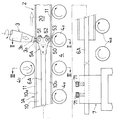
さらに、例えば、図8(A)に示すように、幅方向片側にコ字状の枠部(10)を有する一対の中空押出形材(1C)(1C)を用い、枠部(10)(10)を突き合わせて側片(10a)(10a)同士ならびに側片(10b)(10b)同士を順次摩擦攪拌接合して幅広の中空材を得る際、対向配置した枠部(10)(10)間で構成する中空部内に、前記同様の中受け具を加工ヘッドの当接部位近傍に位置させれば、中空部の上下の接合壁を凹みのない平坦なものとなし得る。
【0024】
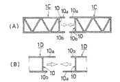
また、長尺材として複数の枠部を有するものを組み合わせ、摩擦攪拌接合により、各接合部に中空部を形成する形で3本以上の長尺材を一体化した中空材とすることも可能である。更に、例えば図8(B)に示すように、枠部(10)の両側片(10a)(10b)の突出長さ(幅)が異なる長尺材(1D)(1D)を、互いの突出長さの長い側片(10a)と短い側片(10b)とが突き合うように配置し、その突き合わせ部を摩擦攪拌接合にて接合一体化することにより、断面矩形の中空部とすることも可能である。しかして、これらの摩擦攪拌接合においても、前記同様の中受け具を用いることにより、接合壁が平坦な中空部を形成できる。
【0025】
なお、この発明では、摩擦攪拌接合における長尺材の移動用として例示したローラーコンベア(4)以外の種々の移送手段を採用できる。しかして、ローラーコンベア(4)としても、押さえローラ(4b)が実施例1のような分割構成でないものも使用可能であり、また移動のために回転駆動するローラと従動回転するローラとを適当に組み合わせた構成としてもよい。一方、中受け具としては、上下一対のローラが離間した構造、第三実施形態とは逆に上側のローラを2個とした構造、上下共に複数個のローラを有する構造等、実施形態以外の様々な構造を採用できる。
【0026】
【発明の効果】
請求項1の発明によれば、長手方向に連続する枠部を有する一対の長尺材より、摩擦攪拌接合にて両コ字枠部の合体による中空部を備えた中空材を製造するに当たり、摩擦攪拌接合用加工ヘッドの当接部位近傍の内側に中受け具を配置することから、両枠部の突き合わせた両側片が該加工ヘッドの押接によって内側へ曲がるのを確実に防止でき、しかも該中受け具が中空部の接合側の内面とこれに対向する内面とに個別に転接するローラを有するため、両長尺材との相対移動における抵抗が小さく、摩擦攪拌接合時の該相対移動を円滑に行えると共に、接合前に該中受け具を両長尺材の中空部となる内側空間へ容易に挿嵌でき、もって接合前の突き合わせ部の形状を保持した高品質の中空材を非常に能率よく製作できる。
【0027】
請求項2の発明によれば、上記の中空材の製造方法において、加工ヘッド及び中受け具を定位置とし、両長尺材を送りローラにて水平移動しつつ摩擦攪拌接合を行うことから、中受け具を加工ヘッドの当接部位近傍に保持するための構造が簡素になるという利点がある。
【図面の簡単な説明】
【図1】 この発明に係る中空材の製造方法の第一実施形態を示す縦断側面図である。
【図2】 図1のII−II線の断面図である。
【図3】 図1のIII −III 線の断面図である。
【図4】 同製造方法の第二実施形態を示す要部の縦断側面図である。
【図5】 同製造方法の第三実施形態を示す要部の縦断正面図である。
【図6】 同製造方法の第四実施形態を示す要部の縦断側面図である。
【図7】 同製造方法の第五実施形態を示す要部の縦断正面図である。
【図8】 この発明を適用する長尺材の他の例を示し、(A)図は中空押出形材の断面図、(B)図は枠部の両側片の突出長さが異なる長尺材の断面図である。
【図9】 従来の摩擦攪拌接合による中空材の製造方法を説明するものであり、(A)図は使用する一対のチャンネル材の断面図、(B)図は両チャンネル材の摩擦攪拌接合による長尺材の接合状況を示す縦断正面図である。
【符号の説明】
1A・・・・・・・チャンネル材(長尺材)
1B・・・・・・・中空押出型材(長尺材)
1C・・・・・・・長尺材
10・・・・・・・コ字枠部
10a,10b・・側片
11・・・・・・・突き合わせ部
2 ・・・・・・・中空材
20・・・・・・・中空部
3 ・・・・・・・摩擦攪拌接合用加工ヘッド
4 ・・・・・・・ローラーコンベア
4a・・・・・・・送りローラ
4b・・・・・・・押さえローラ
5A〜5D・・・・中受け具
51・・・・・・・上部ローラ
52・・・・・・・下部ローラ
6A・・・・・・・角パイプ(保持部材)
6B・・・・・・・索体(保持部材)[0001]
BACKGROUND OF THE INVENTION
The present invention relates to a hollow material in which a U-shaped or U-shaped frame portion continuous in the longitudinal direction of a pair of long materials is abutted, and both frame portions are joined and integrated by friction stir welding to form a hollow portion. It relates to a manufacturing method.
[0002]
[Prior art and its problems]
In recent years, a friction stir welding method has become widespread as a new joining technique replacing metal welding and brazing. As disclosed in JP 7-505090 A, this joining method is performed when a probe made of a material harder than a workpiece (rod-like object) is brought into sliding contact with the workpiece while rotating at high speed. This is based on the fact that the workpiece material is plastically fluidized by the generated frictional heat and pressure, and that the probe is embedded in the workpiece and can be moved in the workpiece in this embedded state. is there.
[0003]
For example, when the probe is moved in the embedded state along the butt joint line between the metal plates, the material of both metal plates plastically flowed on the front side of the probe is gradually transferred to the rear side of the probe while being agitated and kneaded. Then, since the frictional heat is lost on the rear side and the metal plate is rapidly cooled and solidified, the two metal plates are joined together in a state where the raw materials are mixed and completely integrated. In this case, the temperature at which the metal material plastically flows is considerably lower than the melting point, joining is in the category of solid-phase joining, the heat input to the metal material through the joining process is extremely small compared to welding and brazing, and solidification. Since there is no generation of stress due to shrinkage, there is an advantage that deformation or cracking due to thermal strain in the vicinity of the joint is unlikely to occur.
[0004]
By the way, for example, as shown in FIG. 9 (A), two channel members (1A) (1A) are arranged so that their U-shaped frame portions (10) (10) face each other. ) (10b) are joined to each other, and the abutting portions (11) are joined and integrated by the friction stir welding method, respectively, to form a rectangular tube shape having a hollow portion formed by combining the frame portions (10) and (10). A hollow material is obtained. However, as shown in FIG. 5B, in the friction stir welding, since the machining head (3) that rotates at high speed is joined while being pressed against the abutting portion (11), it is supported by the presence of the hollow portion (20). In the absence of this, the both side pieces (10a) and (10a) that are abutted are bent inward by a pressing load, and the joining wall (20a) is easily deformed so as to be recessed, and the product quality of the hollow material (2) obtained thereby is In addition to the reduction, there is a problem that bonding failure occurs in some cases.
[0005]
In order to prevent the above deformation, it is conceivable to insert a suitable receiving material into the hollow portion (20). However, the channel materials (1A) and (1A) are long, and in the joining process. Since the joining position by the processing head is relatively moved at a constant speed, it is necessary to insert the length of the channel material (1A) (1A) over the entire length as the receiving material, and to extract it after joining, It is extremely difficult to operate, and it is difficult to say realistic. Such a problem is not limited to the joining of the illustrated channel members (1A) and (1A), but a pair of long members having a U-shaped or U-shaped frame portion continuous in the longitudinal direction is rubbed. This is a common problem in the case of manufacturing a hollow material having a hollow portion formed by combining both frame portions by joining and integrating by stirring joining.
[0006]
In view of the above-mentioned circumstances, the present invention is such that both frame portions are merged by abutting the U-shaped or U-shaped frame portions that are continuous in the longitudinal direction of a pair of long materials and by friction stir welding. As a method of manufacturing a hollow material having a hollow part, it is possible to reliably prevent the inward bending of both side pieces that faced both frame parts with a simple structure, so that there is no dent in the joining wall of the hollow part, and matching before joining An object of the present invention is to provide means for efficiently producing a high-quality hollow material that maintains the shape of the part.
[0007]
[Means for Solving the Problems]
In order to achieve the above object, a hollow material manufacturing method according to claim 1 of the present invention includes a U-shaped or U-shaped frame portion (including a semicircular frame shape) that is continuous in the longitudinal direction. A pair of long materials having the frame portions are arranged so that the frame portions face each other, and the butted portions of both side pieces of these frame portions are integrated by friction stir welding, so that the hollow portion by combining both the frame portions is formed. In manufacturing the provided hollow material, in the hollow portion configured between the frame portions facing each other of the pair of long materials, a roller that rolls on the inner surface on the joining side by friction stir welding, and an inner surface that faces the inner surface A middle holder provided with a roller for rolling contact is loaded, and the middle holder is positioned in the vicinity of the contact portion of the friction stir welding machining head by the holding means, and both long materials are relative to the machining head. It is characterized by being moved and joined together There.
[0008]
In the above configuration, even when the processing head is pressed against the abutting portions of the both side pieces of the two frame portions in the joint integration by friction stir welding of both long materials, the inner portion in the vicinity of the pressed portion is supported by the intermediate holder. Therefore, it is suppressed that both side pieces are bent inward, and no dent is generated in the joining wall. Thus, since the intermediate holder has a small resistance due to the rolling of each roller in contact with the inner surface on the opposite side to the inner surface on the opposite side in the relative movement with the long material, the relative movement at the time of friction stir welding is reduced. It can be performed smoothly and can be easily inserted into the inner space that is the hollow portion of both long materials before joining.
[0009]
According to a second aspect of the present invention, in the method for producing a hollow material according to the first aspect, the friction stir welding by the processing head is performed at a fixed position while horizontally moving both long materials in the longitudinal direction via a feed roller. By fixing the other end of the holding member, one end of which is connected to the intermediate receiving member as the holding means, to the outside on the upstream side or the downstream side in the moving direction of the two long materials, the intermediate receiving member is in the vicinity of the contact portion of the machining head It is trying to be located in. In this case, since the friction stir welding is performed while horizontally moving both the long materials with the processing head as a fixed position, the intermediate receiver may be set at the fixed position by the holding member. As this holding member, a rod-like material such as a pipe or a shaft or a cable body such as a wire can be used.
[0010]
DETAILED DESCRIPTION OF THE INVENTION
Embodiments of the present invention will be specifically described below with reference to the drawings. 1 to 3 show the first embodiment, FIG. 4 shows the second embodiment, FIG. 5 shows the third embodiment, FIG. 6 shows the fourth embodiment, and FIG. 7 shows the fifth embodiment.
[0011]
1 to 3, (1A) is a channel material made of a long aluminum alloy or the like obtained as an extruded profile, and two of them are frame portions (10) and (10) having a U-shaped cross section. In a state where the both side pieces (10a) and (10b) are opposed to each other, they are placed horizontally on the feed rollers (4a) arranged at predetermined intervals of the roller conveyor (4), and these feed rollers ( 4a) and the pressing rollers (4b) provided at the important points are sent in one direction at a constant speed. Each pressing roller (4b) is divided into left and right pairs, each of which can be moved up and down and moved in the axial direction, and the pressing position can be adjusted according to the side piece width of the channel material used.
[0012]
(3) is a processing head for friction stir welding, which is installed so as to be able to move up and down at a fixed position in the upper direction of the travel of the roller conveyor (4), and a shoulder portion around the base portion of the protruding shaft portion (3a) provided at the tip. 3b). Thus, in the hollow portion (20) formed between the frame portions (10) and (10) where the two channel members (1A) and (1A) are abutted, a square pipe in which the intermediate holder (5A) is a holding member. It is loaded via (6A) so as to be located directly under the machining head (3). Further, the roller conveyor (4) is set so that one feed roller (4a) is arranged at a position directly below the processing head (3).
[0013]
In this middle holder (5A), a pair of upper and lower rollers (51) and (52) are attached to a frame (50) fixed to one end of a square pipe (6A) by a pivot (53) so as to be freely rotatable. The upper roller (51) is in rolling contact with the upper inner surface of the hollow portion (20), the lower roller (52) is in contact with the lower inner surface, and both rollers (51) (52) are also in contact with each other. It is configured as follows. And the other end side of a square pipe (6A) is derived | led-out from the rear end of both channel material (1A) (1A) which faced, and the clamp apparatus (7) installed in the rear end part of the roller conveyor (4) It is held immovably via the lock bolts (71) and (71).
[0014]
In the above configuration, in order to produce a hollow material from both channel materials (1A) (1A), both channel materials (1A) (1A) butted directly below the processing head (3) are in the upper standby position. ) Is positioned, the processing head (3) is lowered while rotating at high speed, and is pressed against the abutting portion (11) of the side pieces (10a) (10a). As a result, the material of the abutting portion (11) is plastically flowed, and the protruding shaft portion ( 3a ) is embedded in the abutting portion (11). In this embedded state, the roller conveyor (4) is driven and both channel materials are driven. (1A) By sending (1A) at a constant speed in the direction of the arrow, the material plastically flowed by frictional heat and pressure on the front side of the projecting shaft portion ( 3a ) is stirred and kneaded while the projecting portion ( 3a ) It gradually moves to the rear side, and at this rear side, it loses frictional heat and rapidly cools and solidifies, so that the abutted side pieces (10a) and (10a) are completely joined and integrated. The machining head (3) is set in a state in which the axis is slightly inclined backward to the downstream side in the feed direction of the roller conveyor (4), and thereby the plastically flowed material is pressed from above by the shoulder portion ( 3b ) and the joining surface is set. It is to level out.
[0015]
In this friction stir welding, a load is applied to the upper side pieces (10a) and (10a) of both the frame portions (10) and (10) by pressing against the butted portion (11) of the processing head (3). The side pieces (10a) and (10a) are supported by the intermediate support (5A) in the hollow portion (20) immediately below the pressing position, and the pressing load is applied to the intermediate support (5A) and the lower side piece ( 10b) Since it is received by the feed roller ( 4a ) of the roller conveyor (4) through (10b), the side piece (10a) (10a) on the joining side is not bent inward, and the hollow portion formed ( The upper joining wall (21) of 20) becomes flat. In addition, when the two channel members (1A) (1A) move during the joining process, the middle receiving tool (5A) in a fixed position is in contact with the upper and lower rollers (51) (51) ( 52) rolls naturally, so the resistance to the inner support (5A) is small and smooth movement is possible.
[0016]
Thus, after both channel materials (1A) and (1A) are joined and integrated at the upper abutting portion (11), the upper and lower parts of the integrated body are reversed and placed on the roller conveyor (4) as before, By inserting the intermediate holder (5A) into the hollow part (20) and joining and integrating the butted parts (11) of the side pieces (10b) and (10b) by friction stir welding as before, A rectangular tube-shaped hollow material (2) having a hollow portion (20) formed by combining both frame portions (10) and (10) is obtained. This hollow material (2) has a flat joint wall (21) on both sides of the hollow portion (20) and has high quality.
[0017]
In the second embodiment shown in FIG. 4, the square pipe (6A) as a holding member in the intermediate holder (5A) is fixed to the frame (50) at one end and both channels are abutted against each other. It leads out from the front end of material (1A) (1A), and is hold | maintained at the clamp apparatus (7) of a roller conveyor (4). Other configurations are the same as those of the first embodiment shown in FIGS.
[0018]
In the third embodiment shown in FIG. 5, the structure for the same purpose as in the first embodiment is provided in the hollow portion (20) between the channel materials (1 A) and (1 A) placed on the roller conveyor (4). Different medium receptacles (5B) are loaded. The inner support (5B) is rolled onto the upper and lower inner surfaces of the hollow portion (20) by one upper roller (51) and two lower rollers (52a) (52b) attached to the frame (50). Since it can maintain a stable posture in the hollow portion (20) in contact with itself, the other end of the cable body (6B) such as a wire having one end connected to the frame body (50) is connected to both channel members (1A) ( 1A) is fixed to the outside of the upstream side in the feed direction (not shown) and is held at a position directly below the machining head (3).
[0019]
In said 1st thru | or 3rd embodiment, although the intermediate | middle receptacle (5A) (5B) is set in the position directly under a process head (3), it embedded in the butt | matching part (11) during friction stir welding. When the projecting shaft portion (3a) of the machining head (3) slightly protrudes into the hollow portion (20), the upper roller (51) is provided with the projecting shaft to avoid interference with the projecting shaft portion (3a). You may set so that it may become a position which leaves | separates from the axial direction (3a) slightly, especially the position which leaves | separates to the feed direction upstream of both channel material (1A) (1A), in order to avoid a contact with the raw material which carried out plastic flow. Further, for the purpose of avoiding the above interference, an annular recess (51a) may be provided at the center of the peripheral surface of the upper roller (51) as in the case of the fourth embodiment (5C) shown in FIG. Good.
[0020]
The present invention is not limited to the illustrated channel material (1A), and various long materials having U-shaped or U-shaped frame portions that are continuous in the longitudinal direction are used as raw materials, and these frame portions are combined. Any of the methods can be applied when manufacturing a hollow material having a hollow portion.
[0021]
For example, as shown in FIG. 7, two extruded shaped long members (1B) (1B) having semicircular frame sections (10) and (10) as U-shaped frame sections are used. When the abutting portions (11) and (11) are sequentially friction stir welded to obtain a hollow material with a circular cross section, the same as described above, in the hollow portion configured in the frame portions (10) and (10) arranged opposite to each other If the middle receptacle (5D) is positioned in the vicinity of the contact portion of the machining head (3), the upper and lower joining walls of the hollow portion can be formed in an arc shape without a dent.
[0022]
In this embodiment, the peripheral surfaces of the upper roller (51) and the lower roller (52) of the intermediate receptacle (5D) are formed as arc surfaces corresponding to the inner arc surface of the hollow material. Further, the peripheral surfaces of the feed roller (4a) and the pressing roller (4b) are also formed as arcuate surfaces corresponding to the outer peripheral shape of the hollow material.
[0023]
Furthermore, for example, as shown in FIG. 8 (A), a pair of hollow extruded profiles (1C) (1C) having a U-shaped frame (10) on one side in the width direction are used, and the frame (10) ( 10) and the side pieces (10a) and (10a) and the side pieces (10b) and (10b) are sequentially friction stir welded to obtain a wide hollow material, and the frame portions (10) and (10) arranged opposite to each other If the same intermediate receiver as described above is positioned in the vicinity of the contact portion of the machining head in the hollow portion formed between them, the upper and lower joining walls of the hollow portion can be made flat without dents.
[0024]
It is also possible to combine a material having a plurality of frames as a long material, and to form a hollow material in which three or more long materials are integrated by forming a hollow portion at each joint by friction stir welding. It is. Further, as shown in FIG. 8B, for example, long materials (1D) and (1D) having different projecting lengths (widths) of both side pieces (10a) and (10b) of the frame portion (10) are projected to each other. A long side piece (10a) and a short side piece (10b) are arranged so as to abut each other, and the abutting part is joined and integrated by friction stir welding to form a hollow part having a rectangular cross section. Is possible. Thus, also in these friction stir welding, a hollow portion with a flat joining wall can be formed by using the same intermediate receptacle as described above.
[0025]
In the present invention, various transfer means other than the roller conveyor (4) exemplified for moving the long material in the friction stir welding can be employed. As the roller conveyor (4), the pressing roller (4b) which is not divided as in the first embodiment can be used, and a roller which is driven to rotate and a roller which is driven to rotate are appropriately used. It is good also as a structure combined with. On the other hand, as the intermediate receiver, a structure in which a pair of upper and lower rollers are separated, a structure having two upper rollers as opposed to the third embodiment, a structure having a plurality of rollers on the upper and lower sides, etc. Various structures can be adopted.
[0026]
【The invention's effect】
According to the invention of claim 1, from the pair of long materials having a frame portion that is continuous in the longitudinal direction, in producing a hollow material having a hollow portion by combining both U-shaped frame portions in friction stir welding, Since the inner support is arranged inside the vicinity of the contact portion of the friction stir welding processing head, it is possible to reliably prevent the both side pieces abutted by both frame portions from bending inward due to the pressing contact of the processing head. Since the inner receiving member has a roller that individually rolls in contact with the inner surface on the joining side of the hollow portion and the inner surface opposite to the inner surface, resistance in relative movement with both long materials is small, and the relative movement during friction stir welding High-quality hollow material that maintains the shape of the butted portion before joining can be easily inserted into the inner space that is the hollow part of both long materials before joining. Can be manufactured efficiently.
[0027]
According to the invention of
[Brief description of the drawings]
FIG. 1 is a vertical side view showing a first embodiment of a method for producing a hollow material according to the present invention.
FIG. 2 is a cross-sectional view taken along the line II-II in FIG.
3 is a cross-sectional view taken along line III-III in FIG.
FIG. 4 is a longitudinal side view of a main part showing a second embodiment of the manufacturing method.
FIG. 5 is a longitudinal sectional front view of an essential part showing a third embodiment of the manufacturing method.
FIG. 6 is a longitudinal sectional side view of a main part showing a fourth embodiment of the manufacturing method.
FIG. 7 is a longitudinal front view of the main part showing a fifth embodiment of the same manufacturing method.
8A and 8B show another example of a long material to which the present invention is applied, in which FIG. 8A is a cross-sectional view of a hollow extruded shape, and FIG. 8B is a long length in which the protruding lengths of both side pieces of the frame portion are different. It is sectional drawing of material.
FIGS. 9A and 9B illustrate a conventional method for producing a hollow material by friction stir welding, wherein FIG. 9A is a sectional view of a pair of channel materials used, and FIG. 9B is a friction stir welding of both channel materials. It is a vertical front view which shows the joining condition of a long material.
[Explanation of symbols]
1A ・ ・ ・ ・ ・ ・ ・ Channel material (long material)
1B .... Hollow extrusion mold material (long material)
1C ····································································································································· 20 ····························································································
6B .... Rope (holding member)
Claims (7)
前記一対の長尺材の対向配置した枠部間で構成する中空部内に、摩擦攪拌接合される突き合わせ部側の内面に転接するローラーと、該内面に対向する内面に転接するローラーとを備えた中受け具を装填し、この中受け具を保持手段により摩擦攪拌接合用加工ヘッドの当接部位近傍に位置させつつ、両長尺材を当該加工ヘッドに対して相対移動させて接合一体化することを特徴とする中空材の製造方法。A pair of long materials having a U-shaped frame section that is continuous in the longitudinal direction are arranged so that the frame sections face each other, and the butted portions of both side pieces of these frame sections are on the outside In producing a hollow material having a hollow portion by combining both frame portions by integrating by friction stir welding by the installed friction stir welding processing head,
In the hollow portion formed between the frame portions opposed to each other of the pair of long materials, a roller that is in rolling contact with the inner surface on the abutting portion side to be friction stir welded, and a roller that is in contact with the inner surface facing the inner surface are provided. An intermediate receiver is loaded, and the long receiver is moved and moved relative to the processing head while the intermediate receiver is positioned near the contact portion of the friction stir welding processing head by the holding means. A method for producing a hollow material characterized by the above.
Priority Applications (1)
| Application Number | Priority Date | Filing Date | Title |
|---|---|---|---|
| JP26479998A JP4191292B2 (en) | 1998-09-18 | 1998-09-18 | Hollow material manufacturing method |
Applications Claiming Priority (1)
| Application Number | Priority Date | Filing Date | Title |
|---|---|---|---|
| JP26479998A JP4191292B2 (en) | 1998-09-18 | 1998-09-18 | Hollow material manufacturing method |
Publications (3)
| Publication Number | Publication Date |
|---|---|
| JP2000094160A JP2000094160A (en) | 2000-04-04 |
| JP2000094160A5 JP2000094160A5 (en) | 2005-10-27 |
| JP4191292B2 true JP4191292B2 (en) | 2008-12-03 |
Family
ID=17408381
Family Applications (1)
| Application Number | Title | Priority Date | Filing Date |
|---|---|---|---|
| JP26479998A Expired - Fee Related JP4191292B2 (en) | 1998-09-18 | 1998-09-18 | Hollow material manufacturing method |
Country Status (1)
| Country | Link |
|---|---|
| JP (1) | JP4191292B2 (en) |
Families Citing this family (4)
| Publication number | Priority date | Publication date | Assignee | Title |
|---|---|---|---|---|
| JP4396803B2 (en) | 2001-05-15 | 2010-01-13 | トヨタ自動車株式会社 | Hollow product manufacturing method and manufacturing apparatus thereof |
| JP4855859B2 (en) * | 2006-07-26 | 2012-01-18 | 本田技研工業株式会社 | Friction stir welding method |
| FR2995237B1 (en) | 2012-09-07 | 2015-05-01 | Airbus Operations Sas | IMPROVED FRICTION MIXING WELDING SYSTEM COMPRISING MOBILE BACK SUPPORT. |
| CN113500348B (en) * | 2021-07-30 | 2023-06-13 | 石家庄永达挂车有限公司 | Semitrailer carriage welding posture adjusting device |
-
1998
- 1998-09-18 JP JP26479998A patent/JP4191292B2/en not_active Expired - Fee Related
Also Published As
| Publication number | Publication date |
|---|---|
| JP2000094160A (en) | 2000-04-04 |
Similar Documents
| Publication | Publication Date | Title |
|---|---|---|
| US6068178A (en) | Friction agitation joining method and friction agitation joining device | |
| JP3398618B2 (en) | Friction stir welding equipment | |
| JP3897391B2 (en) | Friction stir welding method for metal joining members | |
| EP1147847A1 (en) | Method of manufacturing structural body and structural body | |
| JP2007222933A (en) | Friction stir welding method | |
| JP3329281B2 (en) | Aluminum or aluminum alloy sheet joining method | |
| JP4191292B2 (en) | Hollow material manufacturing method | |
| JPH10193139A (en) | Friction stirring welding method | |
| JP3761736B2 (en) | Friction stir welding method | |
| JP2004167498A (en) | Jointing method and extruding shape used for the same | |
| JP3451211B2 (en) | Manufacturing method of hollow material | |
| JP3732668B2 (en) | Friction stir welding method | |
| JP4262812B2 (en) | Friction stir welding method | |
| EP1832373B1 (en) | Adjustable overlap joint and structure produced thereby | |
| JPH11267858A (en) | Friction jointing member and its jointing method, and jointing panel | |
| JP3480913B2 (en) | How to make a structure | |
| JP3761735B2 (en) | Friction stir welding method | |
| JP2004141946A (en) | Double skin panel manufactured by traction swirling joining and method for manufacturing broad panel using the panel | |
| JP3966736B2 (en) | Manufacturing method and manufacturing apparatus of wide width material made of aluminum alloy | |
| JP2005334970A (en) | Friction stir joining method | |
| JP4215999B2 (en) | Method of manufacturing friction stir welding material | |
| JP4209537B2 (en) | Friction stir welding equipment | |
| JP2003531011A (en) | Finned pipe | |
| JP2000094160A5 (en) | ||
| JPH10296462A (en) | Method for friction stirring welding |
Legal Events
| Date | Code | Title | Description |
|---|---|---|---|
| A521 | Written amendment |
Free format text: JAPANESE INTERMEDIATE CODE: A523 Effective date: 20050822 |
|
| A621 | Written request for application examination |
Free format text: JAPANESE INTERMEDIATE CODE: A621 Effective date: 20050822 |
|
| A977 | Report on retrieval |
Free format text: JAPANESE INTERMEDIATE CODE: A971007 Effective date: 20080212 |
|
| A131 | Notification of reasons for refusal |
Free format text: JAPANESE INTERMEDIATE CODE: A131 Effective date: 20080226 |
|
| A521 | Written amendment |
Free format text: JAPANESE INTERMEDIATE CODE: A523 Effective date: 20080424 |
|
| A131 | Notification of reasons for refusal |
Free format text: JAPANESE INTERMEDIATE CODE: A131 Effective date: 20080603 |
|
| A521 | Written amendment |
Free format text: JAPANESE INTERMEDIATE CODE: A523 Effective date: 20080710 |
|
| TRDD | Decision of grant or rejection written | ||
| A01 | Written decision to grant a patent or to grant a registration (utility model) |
Free format text: JAPANESE INTERMEDIATE CODE: A01 Effective date: 20080826 |
|
| A01 | Written decision to grant a patent or to grant a registration (utility model) |
Free format text: JAPANESE INTERMEDIATE CODE: A01 |
|
| A61 | First payment of annual fees (during grant procedure) |
Free format text: JAPANESE INTERMEDIATE CODE: A61 Effective date: 20080918 |
|
| FPAY | Renewal fee payment (event date is renewal date of database) |
Free format text: PAYMENT UNTIL: 20110926 Year of fee payment: 3 |
|
| R150 | Certificate of patent or registration of utility model |
Free format text: JAPANESE INTERMEDIATE CODE: R150 |
|
| FPAY | Renewal fee payment (event date is renewal date of database) |
Free format text: PAYMENT UNTIL: 20110926 Year of fee payment: 3 |
|
| RD02 | Notification of acceptance of power of attorney |
Free format text: JAPANESE INTERMEDIATE CODE: R3D02 |
|
| LAPS | Cancellation because of no payment of annual fees |