JP4188287B2 - Thermal sensor and measuring apparatus using the same - Google Patents
Thermal sensor and measuring apparatus using the same Download PDFInfo
- Publication number
- JP4188287B2 JP4188287B2 JP2004208666A JP2004208666A JP4188287B2 JP 4188287 B2 JP4188287 B2 JP 4188287B2 JP 2004208666 A JP2004208666 A JP 2004208666A JP 2004208666 A JP2004208666 A JP 2004208666A JP 4188287 B2 JP4188287 B2 JP 4188287B2
- Authority
- JP
- Japan
- Prior art keywords
- surface portion
- concentration
- exposed surface
- urea
- heat transfer
- Prior art date
- Legal status (The legal status is an assumption and is not a legal conclusion. Google has not performed a legal analysis and makes no representation as to the accuracy of the status listed.)
- Active
Links
Images


Classifications
-
- G—PHYSICS
- G01—MEASURING; TESTING
- G01N—INVESTIGATING OR ANALYSING MATERIALS BY DETERMINING THEIR CHEMICAL OR PHYSICAL PROPERTIES
- G01N27/00—Investigating or analysing materials by the use of electric, electrochemical, or magnetic means
- G01N27/02—Investigating or analysing materials by the use of electric, electrochemical, or magnetic means by investigating impedance
- G01N27/04—Investigating or analysing materials by the use of electric, electrochemical, or magnetic means by investigating impedance by investigating resistance
- G01N27/14—Investigating or analysing materials by the use of electric, electrochemical, or magnetic means by investigating impedance by investigating resistance of an electrically-heated body in dependence upon change of temperature
- G01N27/18—Investigating or analysing materials by the use of electric, electrochemical, or magnetic means by investigating impedance by investigating resistance of an electrically-heated body in dependence upon change of temperature caused by changes in the thermal conductivity of a surrounding material to be tested
-
- B—PERFORMING OPERATIONS; TRANSPORTING
- B01—PHYSICAL OR CHEMICAL PROCESSES OR APPARATUS IN GENERAL
- B01D—SEPARATION
- B01D53/00—Separation of gases or vapours; Recovering vapours of volatile solvents from gases; Chemical or biological purification of waste gases, e.g. engine exhaust gases, smoke, fumes, flue gases, aerosols
- B01D53/34—Chemical or biological purification of waste gases
- B01D53/46—Removing components of defined structure
- B01D53/54—Nitrogen compounds
- B01D53/56—Nitrogen oxides
-
- G—PHYSICS
- G01—MEASURING; TESTING
- G01F—MEASURING VOLUME, VOLUME FLOW, MASS FLOW OR LIQUID LEVEL; METERING BY VOLUME
- G01F1/00—Measuring the volume flow or mass flow of fluid or fluent solid material wherein the fluid passes through a meter in a continuous flow
- G01F1/68—Measuring the volume flow or mass flow of fluid or fluent solid material wherein the fluid passes through a meter in a continuous flow by using thermal effects
- G01F1/684—Structural arrangements; Mounting of elements, e.g. in relation to fluid flow
- G01F1/6842—Structural arrangements; Mounting of elements, e.g. in relation to fluid flow with means for influencing the fluid flow
-
- G—PHYSICS
- G01—MEASURING; TESTING
- G01F—MEASURING VOLUME, VOLUME FLOW, MASS FLOW OR LIQUID LEVEL; METERING BY VOLUME
- G01F1/00—Measuring the volume flow or mass flow of fluid or fluent solid material wherein the fluid passes through a meter in a continuous flow
- G01F1/68—Measuring the volume flow or mass flow of fluid or fluent solid material wherein the fluid passes through a meter in a continuous flow by using thermal effects
- G01F1/684—Structural arrangements; Mounting of elements, e.g. in relation to fluid flow
- G01F1/688—Structural arrangements; Mounting of elements, e.g. in relation to fluid flow using a particular type of heating, cooling or sensing element
- G01F1/69—Structural arrangements; Mounting of elements, e.g. in relation to fluid flow using a particular type of heating, cooling or sensing element of resistive type
- G01F1/692—Thin-film arrangements
-
- G—PHYSICS
- G01—MEASURING; TESTING
- G01F—MEASURING VOLUME, VOLUME FLOW, MASS FLOW OR LIQUID LEVEL; METERING BY VOLUME
- G01F1/00—Measuring the volume flow or mass flow of fluid or fluent solid material wherein the fluid passes through a meter in a continuous flow
- G01F1/68—Measuring the volume flow or mass flow of fluid or fluent solid material wherein the fluid passes through a meter in a continuous flow by using thermal effects
- G01F1/696—Circuits therefor, e.g. constant-current flow meters
- G01F1/698—Feedback or rebalancing circuits, e.g. self heated constant temperature flowmeters
- G01F1/699—Feedback or rebalancing circuits, e.g. self heated constant temperature flowmeters by control of a separate heating or cooling element
-
- G—PHYSICS
- G01—MEASURING; TESTING
- G01N—INVESTIGATING OR ANALYSING MATERIALS BY DETERMINING THEIR CHEMICAL OR PHYSICAL PROPERTIES
- G01N25/00—Investigating or analyzing materials by the use of thermal means
- G01N25/18—Investigating or analyzing materials by the use of thermal means by investigating thermal conductivity
-
- B—PERFORMING OPERATIONS; TRANSPORTING
- B01—PHYSICAL OR CHEMICAL PROCESSES OR APPARATUS IN GENERAL
- B01D—SEPARATION
- B01D2251/00—Reactants
- B01D2251/20—Reductants
- B01D2251/206—Ammonium compounds
- B01D2251/2067—Urea
-
- B—PERFORMING OPERATIONS; TRANSPORTING
- B01—PHYSICAL OR CHEMICAL PROCESSES OR APPARATUS IN GENERAL
- B01D—SEPARATION
- B01D2257/00—Components to be removed
- B01D2257/40—Nitrogen compounds
- B01D2257/404—Nitrogen oxides other than dinitrogen oxide
-
- F—MECHANICAL ENGINEERING; LIGHTING; HEATING; WEAPONS; BLASTING
- F01—MACHINES OR ENGINES IN GENERAL; ENGINE PLANTS IN GENERAL; STEAM ENGINES
- F01N—GAS-FLOW SILENCERS OR EXHAUST APPARATUS FOR MACHINES OR ENGINES IN GENERAL; GAS-FLOW SILENCERS OR EXHAUST APPARATUS FOR INTERNAL COMBUSTION ENGINES
- F01N2610/00—Adding substances to exhaust gases
- F01N2610/02—Adding substances to exhaust gases the substance being ammonia or urea
Abstract
Description
本発明は、水性液体の熱的性質を利用して当該液体の濃度その他の特性値についての値を測定するのに使用される熱式センサ及びそれを用いた測定装置に関するものである。 The present invention relates to a thermal sensor used to measure the concentration and other characteristic values of an aqueous liquid using the thermal properties of an aqueous liquid, and a measuring apparatus using the same.
本発明の熱式センサ及び測定装置は、例えば自動車の内燃エンジンなどから排出される排ガスを浄化するシステムにおいて窒素酸化物(NOx)の分解のために排ガス浄化触媒に噴霧される尿素水溶液の尿素濃度を測定するのに利用することができる。 The thermal sensor and the measuring device of the present invention provide a urea concentration of an aqueous urea solution sprayed on an exhaust gas purification catalyst for decomposing nitrogen oxides (NOx) in a system for purifying exhaust gas discharged from, for example, an internal combustion engine of an automobile. Can be used to measure
自動車の内燃エンジンではガソリンや軽油などの化石燃料が燃焼される。これに伴って発生する排ガス中には、水や二酸化炭素などと共に、未燃焼の一酸化炭素(CO)及び炭化水素(HC)や、硫黄酸化物(SOx)や、窒素酸化物(NOx)等の環境汚染物質が含まれる。近年、特に環境保護及び生活環境の汚染防止のため、これら自動車の排ガスを浄化すべく各種の対策が講じられている。 An automobile internal combustion engine burns fossil fuels such as gasoline and light oil. In the exhaust gas generated along with this, together with water, carbon dioxide, etc., unburned carbon monoxide (CO) and hydrocarbons (HC), sulfur oxide (SOx), nitrogen oxide (NOx), etc. Of environmental pollutants. In recent years, various measures have been taken to purify the exhaust gas of these automobiles, particularly in order to protect the environment and prevent pollution of the living environment.
このような対策の1つとして、排ガス浄化触媒装置の使用が挙げられる。これは、排気系の途中に排ガス浄化用三元触媒を配置し、ここで、CO、HC、NOx等を酸化還元により分解して、無害化を図るものである。触媒装置でのNOxの分解を継続的に維持するために、排気系の触媒装置のすぐ上流側から触媒に対して尿素水溶液が噴霧される。この尿素水溶液は、NOx分解の効果を高めるためには特定の尿素濃度範囲にあることが必要とされ、特に尿素濃度32.5%が最適であるとされている。 One such measure is the use of an exhaust gas purification catalyst device. In this method, a three-way catalyst for exhaust gas purification is arranged in the middle of the exhaust system, and CO, HC, NOx, etc. are decomposed by oxidation-reduction to make them harmless. In order to continuously maintain the decomposition of NOx in the catalyst device, an aqueous urea solution is sprayed onto the catalyst from the upstream side of the exhaust catalyst device. This urea aqueous solution needs to be in a specific urea concentration range in order to enhance the effect of NOx decomposition, and the urea concentration of 32.5% is particularly optimal.
尿素水溶液は、自動車に搭載される尿素水溶液タンクに収容されるのであるが、経時的に濃度変化が生ずることがあり、また、タンク内において局所的に濃度分布の不均一が発生することもある。タンクからポンプにより供給管を介して噴霧ノズルへと供給される尿素水溶液は、一般にタンクの底部に近い出口から採取されるので、この領域のものが所定の尿素濃度であることが触媒装置の効率を高めるためには重要である。 The urea aqueous solution is accommodated in a urea aqueous solution tank mounted on an automobile, but the concentration may change over time, and the concentration distribution may be locally uneven in the tank. . Since the urea aqueous solution supplied from the tank to the spray nozzle through the supply pipe by the pump is generally collected from the outlet near the bottom of the tank, the efficiency of the catalyst device is that the concentration in this region is a predetermined urea concentration. It is important to increase
しかるに、従来は、尿素水溶液中の尿素濃度の直接的測定はなされていない。また、排気系において、触媒装置の上流側と下流側とにそれぞれNOxセンサーを配置し、これらセンサーで検知されるNOx濃度の差異に基づきNOxの分解が最適に行われたか否かを判別することがなされている。しかし、この手法は、実際にNOxを低減した効果を測定するものであるので、尿素水溶液噴霧の前にはもちろんのこと噴霧当初においても、液体が所定の尿素濃度の尿素水溶液であるか否かの識別を行うことはできない。また、このような方法で使用されるNOxセンサーは、所定の尿素濃度範囲内の尿素水溶液の噴射を実現するためには感度が十分とは云えなかった。 However, conventionally, the direct measurement of the urea concentration in the aqueous urea solution has not been made. Further, in the exhaust system, NOx sensors are arranged on the upstream side and the downstream side of the catalyst device, respectively, and it is determined whether or not the NOx decomposition is optimally performed based on the difference in the NOx concentration detected by these sensors. Has been made. However, since this method measures the effect of actually reducing NOx, whether or not the liquid is a urea aqueous solution having a predetermined urea concentration at the beginning of the spraying as well as before the urea aqueous solution spraying. Cannot be identified. In addition, the NOx sensor used in such a method cannot be said to have sufficient sensitivity to realize injection of an aqueous urea solution within a predetermined urea concentration range.
ところで、特開平11−153561号公報(特許文献1)には、通電により発熱体を発熱させ、この発熱により感温体を加熱し、発熱体から感温体への熱伝達に対し被識別流体により熱的影響を与え、感温体の電気抵抗に対応する電気的出力に基づき、被識別流体の種類を判別する流体識別方法であって、発熱体ヘの通電を周期的に行う方法が開示されている。即ち、ここでは熱式センサが使用されている。 By the way, in JP-A-11-153561 (Patent Document 1), a heating element is heated by energization, the temperature sensing element is heated by this heating, and a fluid to be identified for heat transfer from the heating element to the temperature sensing element. Disclosed is a fluid identification method for discriminating the type of fluid to be identified based on the electrical output corresponding to the electrical resistance of the temperature sensing element, and periodically energizing the heating element Has been. That is, here, a thermal sensor is used.
しかしながら、この流体識別方法は、たとえば水と空気と油などの性状のかなり異なる物質に対して、代表値によって流体識別を行うことが可能であるが、上記の様な被測定液体が所定の尿素濃度の尿素水溶液であるか否かの識別に適用して正確で迅速な識別を行うことは困難である。 However, in this fluid identification method, for example, fluid identification can be performed by using representative values for substances having considerably different properties such as water, air, and oil. It is difficult to perform accurate and rapid identification by applying to the identification of whether or not the urea aqueous solution has a concentration.
また、熱式センサが利用される代表的な用途として、流体の質量流量測定が例示される。このような用途の熱式流量センサ及びそれを用いた流量計(流量測定装置)については、たとえば特開平11−153465号公報(特許文献2)、特開平11−153466号公報(特許文献3)、特開2002−202166号公報(特許文献4)、特開2003−279395号公報(特許文献5)及び特開2003−302271号公報(特許文献6)に記載がある。
以上のような熱式センサとくに上記特許文献1〜6に記載されているような傍熱型の熱式センサにおいては、被測定流体が液体である場合には、その中に溶存する空気等が温度上昇などにより気化して気泡となり、この気泡がセンサの外面に付着することがある。また、同様に被測定流体が液体である場合には、たとえば液体がタンク内に収容されていて該タンク内に液体の自由表面があると、該タンク内液体が揺動することで液面が波立って、該液面に接する空気などの気体が液体中に巻き込まれて液体中に気泡となって残留し、この気泡がセンサ外面に付着することもある。
In the above-described thermal sensor, particularly in the indirectly heated thermal sensor as described in
特に、上記自動車に搭載されるタンク中の尿素水溶液の場合には、自動車走行時に外力に基づく激しい揺動が繰り返されるので、上記センサ外面への気泡の付着は著しい。 In particular, in the case of the urea aqueous solution in the tank mounted on the automobile, since the violent rocking based on the external force is repeated when the automobile is running, the adhesion of bubbles to the outer surface of the sensor is remarkable.
センサに気泡が付着すると、センサの発熱体から発せられる熱が熱伝達部材を介して液体に良好に伝達されなくなり、また液体から熱伝達部材を介して感温体に良好に熱伝達がなされなくなる。このように、センサと被測定液体との間の熱伝達が正常になされなくなると、被測定液体の濃度測定値に大きな誤差が発生して測定の信頼性が著しく低下するおそれがある。 When bubbles are attached to the sensor, heat generated from the heating element of the sensor is not transferred to the liquid through the heat transfer member, and heat is not transferred from the liquid to the temperature sensing member through the heat transfer member. . As described above, when the heat transfer between the sensor and the liquid to be measured is not normally performed, a large error occurs in the concentration measurement value of the liquid to be measured, and the reliability of the measurement may be significantly reduced.
本発明は、以上のような現状に鑑みて、とくに被測定物が水性液体である場合において、センサ外面への気泡の付着が低減され、測定精度の向上が可能な熱式センサ及びそれを用いた測定装置を提供することを目的とするものである。 In view of the present situation as described above, the present invention uses a thermal sensor capable of reducing the adhesion of bubbles to the outer surface of the sensor and improving the measurement accuracy, particularly when the object to be measured is an aqueous liquid. It is an object to provide a measuring apparatus.
本発明によれば、上記目的を達成するものとして、
感温体を含んでなる検知素子と、該検知素子を封止する樹脂モールドと、前記検知素子及び水性の被測定液体の間での熱伝達を行う熱伝達部材と、を備えた熱式センサであって、
前記熱伝達部材の一部は前記樹脂モールドから露出して露出表面部を形成しており、該露出表面部に親水性膜が付されていることを特徴とする熱式センサ、
が提供される。
According to the present invention, the above object is achieved as follows:
A thermal sensor comprising: a sensing element including a temperature sensing element; a resin mold that seals the sensing element; and a heat transfer member that conducts heat between the sensing element and an aqueous liquid to be measured. Because
A part of the heat transfer member is exposed from the resin mold to form an exposed surface portion, and the exposed surface portion is provided with a hydrophilic film,
Is provided.
本発明の一態様においては、前記親水性膜は酸化シリコン膜である。本発明の一態様においては、前記熱伝達部材の露出表面部の周囲に位置する前記樹脂モールドの表面部分にも前記親水性膜が付されている。本発明の一態様においては、前記検知素子は発熱体をも含んでなる。 In one embodiment of the present invention, the hydrophilic film is a silicon oxide film. In one aspect of the present invention, the hydrophilic film is also applied to the surface portion of the resin mold located around the exposed surface portion of the heat transfer member. In one aspect of the present invention, the sensing element also includes a heating element.
更に、本発明によれば、上記目的を達成するものとして、以上のような熱式センサと、該熱式センサの出力に基づき前記被測定液体の特性値を算出する演算部とを含んでなることを特徴とする測定装置、が提供される。 Furthermore, according to the present invention, to achieve the above object, the above-described thermal sensor and a calculation unit that calculates the characteristic value of the liquid to be measured based on the output of the thermal sensor are included. A measuring device is provided.
本発明の一態様においては、前記熱式センサの周囲に前記熱伝達部材の露出表面部の近傍を通る前記被測定液体のための流通路が形成されており、該流通路を形成する部材の前記熱伝達部材の露出表面部に面する表面の部分にも親水性膜が付されている。本発明の一態様においては、前記被測定液体は尿素水溶液であり、前記演算部は前記被測定液体の尿素濃度を算出するよう構成されている。 In one aspect of the present invention, a flow path for the liquid to be measured that passes near the exposed surface portion of the heat transfer member is formed around the thermal sensor, and the member forming the flow path is provided. A hydrophilic film is also attached to a portion of the surface facing the exposed surface portion of the heat transfer member. In one aspect of the present invention, the liquid to be measured is an aqueous urea solution, and the calculation unit is configured to calculate the urea concentration of the liquid to be measured.
本発明によれば、検知素子を封止する樹脂モールドの表面から露出する熱伝達部材の露出表面部に親水性膜を付することで、該表面部の水性被測定液体に対する濡れ性を向上させることができ、かくして、水性被測定液体中の溶存空気等や該水性被測定液体とその自由表面を介して接している空気等の気体が水性被測定液体中に気泡化しても、その気泡が熱伝達部材の露出表面部に付着しにくくなり、このため検知素子と水性被測定液体との間での熱伝達が良好になされ、測定精度が向上する。 According to the present invention, the hydrophilic film is attached to the exposed surface portion of the heat transfer member exposed from the surface of the resin mold that seals the sensing element, thereby improving the wettability of the surface portion with respect to the aqueous measurement liquid. Thus, even if a gas such as dissolved air in the aqueous measurement liquid or air in contact with the aqueous measurement liquid through its free surface is bubbled into the aqueous measurement liquid, the bubbles are not generated. It becomes difficult to adhere to the exposed surface portion of the heat transfer member, so that heat transfer between the sensing element and the aqueous liquid to be measured is improved, and measurement accuracy is improved.
以下、本発明の実施の形態を、図面を参照しながら説明する。 Hereinafter, embodiments of the present invention will be described with reference to the drawings.
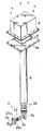
図1は本発明による熱式センサ及びそれを用いた測定装置の一実施形態を示す分解斜視図であり、図2はその一部省略断面図であり、図3はそのタンクへの取り付け状態を示す図である。本実施形態は、被測定液体が尿素水溶液であり、その特性値としての尿素濃度が測定されるものである。なお、本実施形態の測定装置では検出された尿素濃度が所定範囲内のものであるか否かの識別(尿素濃度による尿素水溶液の識別または単に尿素濃度の識別ということもある)をも行っており、このため、以下の説明では尿素濃度測定または尿素濃度測定装置を尿素濃度識別または尿素濃度識別装置ということもある。 FIG. 1 is an exploded perspective view showing an embodiment of a thermal sensor and a measuring apparatus using the same according to the present invention, FIG. 2 is a partially omitted cross-sectional view thereof, and FIG. FIG. In the present embodiment, the liquid to be measured is a urea aqueous solution, and the urea concentration as a characteristic value thereof is measured. In the measurement apparatus of the present embodiment, identification of whether or not the detected urea concentration is within a predetermined range is also performed (the urea aqueous solution may be identified by the urea concentration or simply the urea concentration may be identified). For this reason, in the following description, the urea concentration measurement or urea concentration measurement device may be referred to as urea concentration identification or urea concentration identification device.
図3に示されているように、たとえば自動車に搭載された排ガス浄化システムを構成するNOx分解用の尿素溶液タンク100の上部には開口部102が設けられており、該開口部に本発明による尿素濃度識別装置104が取り付けられている。タンク100には、尿素溶液が注入される入口配管106及び尿素溶液が取り出される出口配管108が設けられている。出口配管108は、タンク100の底部に近い高さ位置にてタンクに接続されており、尿素溶液供給ポンプ110を介して不図示の尿素溶液噴霧器に接続されている。排気系において排ガス浄化用触媒装置の直前に配置された上記尿素溶液噴霧器により触媒装置に対する尿素溶液の噴霧が行われる。
As shown in FIG. 3, for example, an
尿素濃度識別装置は、濃度識別センサー部2と支持部4とを備えている。支持部4の一方の端部(下端部)に濃度識別センサー部2が取り付けられており、支持部4の他方の端部(上端部)にはタンク開口部102へ取り付けるための取り付け部4aが設けられている。
The urea concentration identification apparatus includes a concentration
濃度識別センサー部2は、発熱体及び感温体を含んでなる傍熱型濃度検知部21と尿素溶液の温度を測定する液温検知部22とを有する。傍熱型濃度検知部21と液温検知部22とは、上下方向に一定距離隔てて配置されている。図4に傍熱型濃度検知部21及び液温検知部22の部分を拡大して示し、図5にその断面図を示す。これら傍熱型濃度検知部21及び液温検知部22が、それぞれ本発明でいう熱式センサに該当する。
The concentration
図示されているように、これら傍熱型濃度検知部21と液温検知部22とは、樹脂モールド(例えばシリカ及び/またはカーボン含有エポキシ樹脂からなるもの)23によって一体化されている。図5に示されているように、傍熱型濃度検知部21は、発熱体及び感温体を含んでなる薄膜チップ21a、該薄膜チップと接合材21bにより接合された濃度検知部用熱伝達部材としての金属製フィン21c、及び薄膜チップの発熱体の電極及び感温体の電極とそれぞれボンディングワイヤー21dにより電気的に接続されている外部電極端子21eを有する。上記薄膜チップ21aが本発明でいう検知素子に該当する。即ち、傍熱型濃度検知部21において、検知素子が樹脂モールド23により封止されている。液温検知部22も、同様な構成を有しており、即ち液温検知部用熱伝達部材としての金属製フィン22c及び外部電極端子22eを有し、検知素子が樹脂モールド23により封止されている。
As shown in the figure, the indirectly
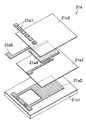
図6に傍熱型濃度検知部21の薄膜チップ21aの分解斜視図を示す。薄膜チップ21aは、たとえばAl2O3からなる基板21a1と、Ptからなる感温体21a2と、SiO2からなる層間絶縁膜21a3と、TaSiO2からなる発熱体21a4及びNiからなる発熱体電極21a5と、SiO2からなる保護膜21a6と、Ti/Auからなる電極パッド21a7とを、順に適宜積層したものからなる。感温体21a2は、図示はされていないが蛇行パターン状に形成されている。尚、液温検知部22の薄膜チップ22aも同様な構造であるが、発熱体を作用させずに感温体22a2のみを作用させる。但し、液温検知部22としては、発熱体を設けないものを使用してもよい。
FIG. 6 shows an exploded perspective view of the
図1及び図2に示されているように、濃度識別センサー部2は支持部4の下端部に取り付けられる基体2aを有しており、この基体の取り付けに際してはO−リング2bが介在せしめられる。基体2aの側面にはO−リング2cを介して上記傍熱型濃度検知部21及び液温検知部22の樹脂モールド23が取り付けられている。基体2aには、濃度検知部用フィン21c及び液温検知部用フィン22cを囲むようにカバー部材2dが付設されている。このカバー部材により、濃度検知部用フィン21c及び液温検知部用フィン22cを順次通って上下方向に延びた上下両端開放の尿素溶液流通路24が形成される。尚、カバー部材2dを基体2aに取り付けることで樹脂モールド23のフランジ部が基体2aの方へと押圧され、これにより樹脂モールド23が基体2aに対して固定されている。
As shown in FIGS. 1 and 2, the density
図4及び図5に示されているように、金属製フィン21c,22cの一部は樹脂モールド23から露出して露出表面部を形成しており、該露出表面部に親水性膜50が付されている。更に好ましくは、金属製フィン21c,22cの露出表面部の周囲に位置する樹脂モールド23の表面部分にも親水性膜50が付されている。即ち、親水性膜50は、金属製フィン21c,22cの露出表面部及びその周囲の樹脂モールド23の表面部分にわたって形成されている。なお、図1及び図2では、親水性膜50は図示を省略されている。
As shown in FIGS. 4 and 5, a part of the
親水性膜50は、例えば酸化シリコン膜である。該酸化シリコン膜50の厚さは、例えば0.01μm〜1μmである。酸化シリコン膜50は、金属製フィン21c,22c及び樹脂モールド23の双方との密着性が良好であり、膜強度も高い。また、酸化シリコン膜50の表面は、金属製フィン21c,22c及び樹脂モールド23のいずれの表面よりも親水性の程度が高い。親水性の程度は対水接触角で表すことができ、一般に対水接触角40°程度以下を親水性としている。酸化シリコン膜50の対水接触角は、40°以下とすることができ、酸化シリコン膜50は親水性を示す。本発明においては、親水性膜50の対水接触角は、好ましくは35°以下であり、より好ましくは30°以下であり、更に好ましくは25°以下であり、特に好ましくは20°以下である。
The
酸化シリコン膜50は、例えばスパッタ、CVD(化学的気相成長法)または塗布剤塗布により形成することができる。このうち、スパッタ及びCVDは、実処理時間が長くかかり、大きな厚さの膜は形成が困難であり、膜形成のための装置構成が大型化する。これに対して塗布剤塗布は、処理が簡単であり、放置時間を別にすれば実処理時間は比較的短くて済むなど、実用上の利点が多い。塗布剤としては、有機珪素化合物を含み、塗布後の反応で酸化シリコン膜が形成されるものを使用することができる。このような塗布剤としては、ポリシラザン例えばパーヒドロポリシラザンと必要に応じて添加されるシランカップリング剤と有機溶媒と必要に応じて使用されるパラジウム触媒またはアミン触媒とを含むもの(例えば、クラリアントジャパン株式会社より入手可能なアクアミカ[登録商標])が例示される。塗布剤塗布及びそれに関連する前後処理の具体的な工程の一例を示せば、次の通りである:
(1)エタノール洗浄工程(塗布剤を塗布すべき表面部分の汚れ除去のため)
(2)キシレン洗浄工程(表面部分の脱脂のため)
(3)乾燥工程(表面部分の水分除去のため:100℃程度、1時間程度)
(4)塗布剤塗布工程(スプレー塗布、刷毛またはウエスによる塗布、フローコート、浸漬塗布などにより行う)
(5)加熱工程(溶媒除去及び酸化シリコン転化のため:125〜200℃、1時間程度)
(6)加熱加湿工程(酸化シリコン転化のため:50〜90℃、80〜95%、3時間程度)
(7)放冷工程
尚、洗浄工程としては、洗浄溶剤として上記のようなエタノールやキシレンを使用するものの他に、洗浄溶剤としてアセトン、イソプロピルアルコールまたはヘキサン等の有機溶剤を使用するものが例示される。
The
(1) Ethanol cleaning process (to remove stains on the surface where the coating agent should be applied)
(2) Xylene cleaning process (for degreasing the surface part)
(3) Drying step (for removing water from the surface portion: about 100 ° C., about 1 hour)
(4) Coating agent coating process (performed by spray coating, brush or waste coating, flow coating, dip coating, etc.)
(5) Heating step (for solvent removal and silicon oxide conversion: 125 to 200 ° C., about 1 hour)
(6) Heating and humidifying step (for silicon oxide conversion: 50 to 90 ° C., 80 to 95%, about 3 hours)
(7) Cooling step The cleaning step is exemplified by using an organic solvent such as acetone, isopropyl alcohol or hexane as the cleaning solvent in addition to the above-described ethanol or xylene as the cleaning solvent. The
上記加熱工程及び加熱加湿工程では、周囲大気中の水(自然に存在するもの又は加湿によるもの)と以下のような転化反応を生じて、酸化シリコン膜が形成される:
-(-SiH2NH-)- + 2H2O → -(-SiO2-)- +NH3 + 2H2
加熱加湿工程を使用することで、加熱工程の加熱温度を低下させることができる。例えば、加熱加湿工程を使用しない場合には、加熱工程の加熱温度は250℃程度となる。
In the heating step and the heating and humidifying step, a silicon oxide film is formed by causing the following conversion reaction with water in the surrounding air (naturally occurring or due to humidification):
- (- SiH 2 NH -) - + 2H 2 O → - (- SiO 2 -) - +
By using the heating and humidifying process, the heating temperature of the heating process can be lowered. For example, when the heating and humidifying process is not used, the heating temperature in the heating process is about 250 ° C.
形成される酸化シリコン膜の厚さは、上記のように例えば0.01μm〜1μmであるが、厚すぎると剥離が生じやすくなり、一方薄すぎると親水性の長期にわたる維持が困難になることがあるので、更に好ましくは0.05μm〜0.8μmである。 The thickness of the silicon oxide film to be formed is, for example, 0.01 μm to 1 μm as described above, but if it is too thick, peeling tends to occur, while if it is too thin, it may be difficult to maintain hydrophilicity for a long time. Therefore, it is more preferably 0.05 μm to 0.8 μm.
図2に示されているように、支持部4の上端部には、後述する濃度検知回路を構成する回路基板6が配置されており、該回路基板を覆って蓋部材8が取り付けられている。支持部4には、濃度識別センサー部2の傍熱型濃度検知部21及び液温検知部22と回路基板6とを電気的に接続する配線10が収納されている。回路基板6には、後述する識別演算部を構成するマイクロコンピュータ(マイコン)が搭載されている。蓋部材8に設けられたコネクタ12を介して、回路基板6と外部との通信のための配線14が設けられている。識別演算部を、回路基板6上ではなしに、外部に配置することもでき、この場合には配線14を介して回路基板6と識別演算部とが接続される。
As shown in FIG. 2, a
以上の濃度識別センサー部2の基体2a及びカバー部材2d、支持部4及び蓋部材8は、いずれも耐腐食性材料たとえばステンレススチールからなる。
The
図7に、本実施形態における濃度識別ための回路の構成を示す。上記の傍熱型濃度検知部21の感温体21a2、液温検知部22の感温体22a2、及び2つの抵抗体64,66によりブリッジ回路68が形成されている。このブリッジ回路68の出力が差動増幅器70に入力され、該差動増幅器の出力(濃度検知回路出力またはセンサー出力ともいう)が不図示のA/D変換器を介して識別演算部を構成するマイコン(マイクロコンピュータ)72に入力される。また、マイコン72には液温検知部22の感温体22a2から液温検知増幅器71を経て尿素水溶液の液温に対応する液温対応出力値が入力される。一方、マイコン72からは傍熱型濃度検知部21の発熱体21a4への通電経路に位置するスイッチ74に対してその開閉を制御するヒーター制御信号が出力される。
FIG. 7 shows the configuration of a circuit for density discrimination in this embodiment. A
以下、本実施形態における尿素濃度測定動作さらには濃度識別動作につき説明する。 Hereinafter, the urea concentration measuring operation and the concentration identifying operation in the present embodiment will be described.
タンク100内に尿素水溶液USが収容されると、濃度識別センサー部2のカバー部材2dにより形成される尿素水溶液導入路24内にも尿素水溶液USが満たされる。尿素水溶液導入路24内を含めてタンク100内の尿素水溶液USは実質上流動しない。
When the urea aqueous solution US is accommodated in the
マイコン72からスイッチ74に対して出力されるヒーター制御信号により、該スイッチ74を所定時間(たとえば4秒間)閉じることで、発熱体21a4に対して所定高さ(たとえば10V)の単一パルス電圧Pを印加して該発熱体を発熱させる。この時の差動増幅器70の出力電圧(センサー出力)Qは、図8に示されるように、発熱体21a4への電圧印加中は次第に増加し、発熱体21a4への電圧印加終了後は次第に減少する。
By closing the
マイコン72では、図8に示されているように、発熱体21a4への電圧印加の開始前の所定時間(たとえば0.1秒間)センサー出力を所定回数(たとえば256回)サンプリングし、その平均値を得る演算を行って平均初期電圧値V1を得る。この平均初期電圧値V1は、感温体21a2の初期温度に対応する。また、図8に示されているように、発熱体21a4への電圧印加の停止前の所定時間(たとえば0.1秒間)センサー出力を所定回数(たとえば256回)サンプリングし、その平均値をとる演算を行って平均ピーク電圧値V2を得る。この平均ピーク電圧値V2は、感温体21a2のピーク温度に対応する。そして、平均初期電圧値V1と平均ピーク電圧値V2との差V0(=V2−V1)を濃度対応電圧値として得る。
In the
一方、このような方法で、尿素濃度既知の幾つかの尿素水溶液(参照尿素水溶液)について、温度と濃度対応電圧値V0との関係を示す検量線を予め得ておき、この検量線をマイコン72の記憶手段に記憶しておく。検量線の例を図9に示す。この例では、尿素濃度0%、20%及び40%の参照尿素水溶液について、検量線が作成されている。 On the other hand, a calibration curve indicating the relationship between temperature and concentration-corresponding voltage value V0 is obtained in advance for several urea aqueous solutions (reference urea aqueous solutions) having a known urea concentration by such a method. Is stored in the storage means. An example of a calibration curve is shown in FIG. In this example, calibration curves are created for reference urea aqueous solutions having urea concentrations of 0%, 20%, and 40%.
図9に示されているように、濃度対応電圧値V0は温度に依存するので、この検量線を用いて測定対象の尿素水溶液の濃度を測定する際には、液温検知部22の感温体22a2から液温検知増幅器71を介して入力される液温対応出力値Tをも用いる。液温対応出力値Tの一例を図10に示す。このような検量線をもマイコン72の記憶手段に記憶しておく。また、互いに異なる温度及び尿素濃度の尿素水溶液で得られた濃度対応電圧値V0と実際の濃度との関係の一例を図11に示す。
As shown in FIG. 9, since the concentration-corresponding voltage value V0 depends on the temperature, when measuring the concentration of the urea aqueous solution to be measured using this calibration curve, the temperature sensitivity of the
図9の検量線において、測定対象の尿素水溶液について得た液温対応出力値Tから図10の検量線を用いて得た温度値tに対応する各検量線の濃度対応電圧値V0(0%;t),V0(20%;t),V0(40%;t)を得る。そして、測定対象の尿素水溶液について得た濃度対応電圧値V0(X;t)が尿素濃度何%に該当するかを、各検量線の濃度対応電圧値V0(0%;t),V0(20%;t),V0(40%;t)の少なくとも2つ(たとえばV0(20%;t),V0(40%;t))を用いた比例演算を行って、決定する。以上のようにして尿素濃度の測定ひいては識別を正確に且つ迅速に(瞬時に)行うことができる。尚、図9の検量線として温度の代わりに液温対応出力値Tを用いたものを採用することで、図10の検量線の記憶を省略することもできる。 In the calibration curve of FIG. 9, the concentration-corresponding voltage value V0 (0%) of each calibration curve corresponding to the temperature value t obtained using the calibration curve of FIG. 10 from the liquid temperature corresponding output value T obtained for the urea aqueous solution to be measured. T), V0 (20%; t), V0 (40%; t). The concentration-corresponding voltage value V0 (X; t) obtained for the urea aqueous solution to be measured corresponds to what percentage of urea concentration the concentration-corresponding voltage values V0 (0%; t), V0 (20 %; T) and V0 (40%; t) (for example, V0 (20%; t), V0 (40%; t)) are used to perform a proportional calculation and determine the value. As described above, the measurement of the urea concentration, and hence the identification, can be performed accurately and quickly (instantly). Note that the calibration curve in FIG. 9 can be omitted by storing the output value T corresponding to the liquid temperature instead of the temperature.
このようにして得られた濃度値を示す信号が不図示のD/A変換器を介して、図7に示される出力バッファ回路76へと出力され、ここからアナログ出力として不図示の自動車のエンジンの燃焼制御などを行うメインコンピュータ(ECU)へと出力される。図12に、この濃度対応のアナログ出力電圧値V0’と実際の濃度との関係の一例を示す。この関係における温度による差異は小さく、十分に実用可能であることが分かる。また、図13に、液温対応のアナログ出力電圧値T’と実際の温度との関係の一例を示す。この液温対応のアナログ出力電圧値T’も上記メインコンピュータ(ECU)へと出力される。一方、濃度値及び液温値を示す信号は、必要に応じてデジタル出力として取り出して、表示、警報その他の動作を行う機器へと入力することができる。
A signal indicating the density value obtained in this way is output to an
更に、液温検知部22から入力される液温対応出力値Tに基づき、尿素水溶液が凍結する温度(−13℃程度)の近くまで温度低下したことが検知された場合に警告を発するようにすることができる。
Furthermore, a warning is issued when it is detected that the temperature of the urea aqueous solution has dropped to near the temperature (about −13 ° C.) based on the liquid temperature corresponding output value T input from the liquid
なお、以上の尿素水溶液の尿素濃度識別は、自然対流を利用して尿素水溶液の動粘度とセンサー出力とが相関関係を有するという原理を利用している。このような濃度識別の精度を高めるためには、濃度検知部用フィン21c及び液温検知部用フィン22cの周囲の尿素水溶液にできるだけ外的要因に基づく強制流動が生じにくくするのが好ましく、この点からカバー部材2dとくに上下方向の尿素水溶液流通路を形成するようにしたものの使用は好ましい。尚、カバー部材2dは、異物の接触を防止する保護部材としても機能する。
The above urea concentration discrimination of the urea aqueous solution uses the principle that the kinematic viscosity of the urea aqueous solution and the sensor output have a correlation using natural convection. In order to improve the accuracy of such concentration identification, it is preferable that forced flow based on external factors be made as difficult as possible in the urea aqueous solution around the concentration
図4に示されているように、カバー部材2dの濃度検知部用フィン21c及び液温検知部用フィン22cの露出表面部に面する表面の部分(即ち内面部分)にも親水性膜50’が付されている。該親水性膜50’は、上記親水性膜50と同様なものである。
As shown in FIG. 4, the
上記のように、排ガス浄化システムにおいて使用される尿素水溶液の尿素濃度は32.5%が最適とされており、たとえば25%〜40%または30%〜35%を適正範囲として定め、この適正範囲を外れた識別結果が得られた場合には、警告を発するようにすることができる。また、タンク内の尿素水溶液が減少して、尿素水溶液流通路24内に尿素水溶液がなくなった場合には、以上のような濃度識別の際に、上記尿素水溶液の濃度適正範囲の場合とは著しくかけ離れた濃度対応電圧値が得られ、この場合にも所要の警告を発するようにすることができる。
As described above, the optimum urea concentration of the urea aqueous solution used in the exhaust gas purification system is 32.5%. For example, 25% to 40% or 30% to 35% is determined as an appropriate range, and this appropriate range is set. A warning can be issued when an identification result outside of the above is obtained. In addition, when the urea aqueous solution in the tank decreases and the urea aqueous solution disappears in the urea aqueous
以上のように、本実施形態においては、金属製フィン21c,22cの露出表面部及びその周囲の樹脂モールド23の表面部分に親水性膜50が付されており、更にカバー部材2dの内面部分にも親水性膜50’が付されているので、これらの表面部、表面部分及び内面部分の尿素水溶液に対する濡れ性を向上させることができる。従って、尿素水溶液中で気泡が発生しても、その気泡は親水性膜50,50’に付着しにくく、更に気泡が付着したとしても上記親水性膜50,50’の濡れ性に基づき気泡は素早く容易に脱落する。このため、検知素子と尿素水溶液との間での熱伝達は良好になされ、高い測定精度が得られる。
As described above, in the present embodiment, the
図14は本発明による熱式センサの更に別の実施形態を示す斜視図であり、図15はその断面図である。これらの図において、上記図1〜図13に関して説明した実施形態のものと同様な機能を有する部材または部分には同一の符号が付されている。 FIG. 14 is a perspective view showing still another embodiment of the thermal sensor according to the present invention, and FIG. 15 is a sectional view thereof. In these drawings, members or portions having functions similar to those of the embodiment described with reference to FIGS.
本実施形態では、濃度検知部用の熱伝達部材21c’及び液温検知部用の熱伝達部材22c’として、外部へと突出しておらず片面のみが樹脂モールド23から露出しているものが使用されている。上記実施形態と同様に、本実施形態においても熱伝達部材21c’,22c’の露出表面部及びその周囲の樹脂モールド23の表面部分に親水性膜50が付されている。尚、図14では親水性膜50は図示を省略されている。
In the present embodiment, as the
以上の実施形態では、被測定液体として尿素水溶液が用いられているが、本発明においては、その他の水性液体を使用してもよい。例えば、図16に示されているように、食塩水溶液や砂糖水溶液などを使用した場合においても、尿素水溶液の場合と同様に、食塩濃度や砂糖濃度が異なる場合には、それに対応して変化するセンサー出力値を得ることができる。但し、図16では、センサー出力値として、尿素水溶液の尿素濃度測定用の検量線を用いたものを示した。しかし、尿素水溶液の場合と同様にして食塩水溶液や砂糖水溶液につきそれぞれ予め作成された検量線を用いることで、正確な食塩濃度値や砂糖濃度値が得られることは当業者にとって自明であろう。 In the above embodiment, an aqueous urea solution is used as the liquid to be measured, but other aqueous liquids may be used in the present invention. For example, as shown in FIG. 16, even when a salt solution or a sugar solution is used, if the salt concentration or the sugar concentration is different as in the case of the urea solution, it changes correspondingly. A sensor output value can be obtained. However, FIG. 16 shows a sensor output value using a calibration curve for measuring the urea concentration of an aqueous urea solution. However, it will be obvious to those skilled in the art that an accurate salt concentration value and sugar concentration value can be obtained by using calibration curves prepared in advance for a salt solution and a sugar solution in the same manner as in the case of a urea solution.
また、以上の実施形態では被測定液体の測定される特性値として水溶液の濃度が採用されているが、本発明で測定される特性値としては、濃度以外に例えば上記動粘度、比重等を挙げることができる。これらの測定に際しては、それぞれの特性項目につき濃度の場合と同様にして予め作成された検量線を用いればよい。また、以上の実施形態では、熱式センサにより測定される特性値として温度(液温検知部22により測定される)も採用されている。 Further, in the above embodiment, the concentration of the aqueous solution is adopted as the characteristic value to be measured of the liquid to be measured, but the characteristic value to be measured in the present invention includes, for example, the kinematic viscosity, specific gravity and the like in addition to the concentration. be able to. In these measurements, a calibration curve prepared in advance in the same manner as in the case of concentration for each characteristic item may be used. Moreover, in the above embodiment, temperature (measured by the liquid temperature detection part 22) is also employ | adopted as a characteristic value measured by a thermal sensor.
以下、実施例により本発明を説明する。 Hereinafter, the present invention will be described by way of examples.
[実施例]
図14〜図15に関し説明した実施形態の熱式センサを用いて図1〜図13に関し説明した実施形態のような尿素濃度測定装置(尿素濃度識別装置)を作製した。ここで、熱式センサの濃度検知部用熱伝達部材21c’及び液温検知部用熱伝達部材22c’は、ステンレススチール(SUS316L)からなる厚さ0.3mmのものであり、樹脂モールドから露出する露出面部の寸法が幅5mmで高さ3mmのものであった。また、樹脂モールド23はシリカ及びカーボン含有エポキシ樹脂からなるものであった。濃度検知部用熱伝達部材21c’及び液温検知部用熱伝達部材22c’、更にはそれらの周囲の樹脂モールド23の表面部分に形成された酸化シリコン膜50は、厚さが0.5μmで、対水接触角が28°であった。酸化シリコン膜50の形成は、アクアミカ[登録商標]NL150Aを用いて、(1)エタノール洗浄工程、(2)キシレン洗浄工程、(3)乾燥工程(100℃、1時間)、(4)アクアミカ塗布工程(スプレーによる塗布)、(5)加熱工程(175℃、1時間)、(6)加熱加湿工程(70℃、90%、3時間)及び(7)放冷工程により行った。
[Example]
Using the thermal sensor according to the embodiment described with reference to FIGS. 14 to 15, a urea concentration measurement device (urea concentration identification device) as in the embodiment described with reference to FIGS. 1 to 13 was produced. Here, the
尿素濃度測定装置の濃度識別センサー部を尿素濃度32.5%の尿素水溶液中に入れ、該尿素水溶液を35℃に加温した。加温開始から1時間後に、測定装置出力としての尿素濃度値を得た。以上のような測定サイクルを10回実行し、それぞれの測定で得られた尿素濃度値の真値(32.5%)からのずれ量の絶対値の10回測定についての平均値を得たところ、1%であった。測定精度は十分に高い。 The concentration identification sensor part of the urea concentration measuring device was placed in a urea aqueous solution having a urea concentration of 32.5%, and the urea aqueous solution was heated to 35 ° C. One hour after the start of heating, a urea concentration value was obtained as a measurement device output. The measurement cycle as described above was executed 10 times, and an average value of 10 absolute measurements of the absolute value of the deviation amount from the true value (32.5%) of the urea concentration value obtained in each measurement was obtained. 1%. The measurement accuracy is high enough.
[比較例]
熱式センサに酸化シリコン膜50を付さないこと以外は実施例と同様にして、熱式センサ及び尿素濃度測定装置(尿素濃度識別装置)を作製した。
[Comparative example]
A thermal sensor and a urea concentration measuring device (urea concentration identifying device) were produced in the same manner as in the example except that the
実施例と同様な測定サイクルを5回繰り返し、それぞれの測定で得られた尿素濃度値の真値(32.5%)からのずれ量の絶対値の10測定についての平均値を得たところ、18%であった。測定精度は低い。 The measurement cycle similar to the example was repeated 5 times, and the average value for 10 measurements of the absolute value of the deviation from the true value (32.5%) of the urea concentration value obtained in each measurement was obtained. 18%. Measurement accuracy is low.
2 濃度識別センサー部
2a 基体
2b,2c O−リング
2d カバー部材
21 傍熱型濃度検知部
21a 薄膜チップ
21b 接合材
21c,22c 金属製フィン
21c’,22c’ 熱伝達部材
21d ボンディングワイヤー
21e,22e 外部電極端子
21a1 基板
21a2,22a2 感温体
21a3 層間絶縁膜
21a4 発熱体
21a5 発熱体電極
21a6 保護膜
21a7 電極パッド
22 液温検知部
23 樹脂モールド
24 尿素水溶液流通路
4 支持部
4a 取り付け部
6 回路基板
8 蓋部材
10,14 配線
12 コネクタ
50,50’ 親水性膜
64,66 抵抗体
68 ブリッジ回路
70 差動増幅器
71 液温検知増幅器
72 マイコン(マイクロコンピュータ)
74 スイッチ
76 出力バッファ回路
100 尿素水溶液タンク
102 開口部
104 尿素濃度識別装置
106 入口配管
108 出口配管
110 尿素水溶液供給ポンプ
US 尿素水溶液
2 Concentration
74
Claims (8)
前記感温体は、通電により発生した熱を検知し、
前記演算部は、前記通電の開始時の前記感温体の温度に対応する第1の出力値と前記通電の開始から時間経過時の前記感温体の温度に対応する第2の出力値とに基づいて、前記特性値を算出するものであり、
前記熱伝達部材の一部は前記樹脂モールドから露出して熱伝達部材露出表面部を形成しており、
前記熱伝達部材露出表面部の近傍を通る前記被測定液体のための流通路が形成されており、
前記熱伝達部材露出表面部、及び/または、前記樹脂モールドの一部が前記流通路に露出して形成される樹脂モールド露出表面部、及び/または、前記流通路を形成する部材の内面部分が親水性であることを特徴とする測定装置。 A thermal sensor comprising: a sensing element including a temperature sensing element; a resin mold that seals the sensing element; and a heat transfer member that conducts heat between the sensing element and an aqueous liquid to be measured. And a calculation device including a calculation unit that calculates a characteristic value of the liquid to be measured based on an output of the thermal sensor,
The temperature sensing element detects heat generated by energization,
The calculation unit includes a first output value corresponding to the temperature of the temperature sensing body at the start of the energization, and a second output value corresponding to the temperature of the temperature sensing body at the elapse of time from the start of energization. Based on the above, the characteristic value is calculated,
A part of the heat transfer member is exposed from the resin mold to form a heat transfer member exposed surface portion,
A flow path for the liquid to be measured passing near the exposed surface portion of the heat transfer member is formed;
The heat transfer member exposed surface portion and / or the resin mold exposed surface portion formed by exposing a part of the resin mold to the flow passage and / or the inner surface portion of the member forming the flow passage A measuring apparatus characterized by being hydrophilic.
Priority Applications (6)
| Application Number | Priority Date | Filing Date | Title |
|---|---|---|---|
| JP2004208666A JP4188287B2 (en) | 2004-07-15 | 2004-07-15 | Thermal sensor and measuring apparatus using the same |
| EP05755231A EP1770389B1 (en) | 2004-07-15 | 2005-06-28 | Thermal sensor and measurement device using the same |
| US11/632,366 US7934868B2 (en) | 2004-07-15 | 2005-06-28 | Thermal sensor and measurement device using the same |
| AT05755231T ATE504828T1 (en) | 2004-07-15 | 2005-06-28 | THERMAL SENSOR AND MEASURING DEVICE USING SAME |
| DE602005027353T DE602005027353D1 (en) | 2004-07-15 | 2005-06-28 | THERMAL SENSOR AND MEASUREMENT DEVICE THEREFOR |
| PCT/JP2005/011791 WO2006008920A1 (en) | 2004-07-15 | 2005-06-28 | Thermal sensor and measurement device using the same |
Applications Claiming Priority (1)
| Application Number | Priority Date | Filing Date | Title |
|---|---|---|---|
| JP2004208666A JP4188287B2 (en) | 2004-07-15 | 2004-07-15 | Thermal sensor and measuring apparatus using the same |
Publications (3)
| Publication Number | Publication Date |
|---|---|
| JP2006029956A JP2006029956A (en) | 2006-02-02 |
| JP2006029956A5 JP2006029956A5 (en) | 2007-11-01 |
| JP4188287B2 true JP4188287B2 (en) | 2008-11-26 |
Family
ID=35785043
Family Applications (1)
| Application Number | Title | Priority Date | Filing Date |
|---|---|---|---|
| JP2004208666A Active JP4188287B2 (en) | 2004-07-15 | 2004-07-15 | Thermal sensor and measuring apparatus using the same |
Country Status (6)
| Country | Link |
|---|---|
| US (1) | US7934868B2 (en) |
| EP (1) | EP1770389B1 (en) |
| JP (1) | JP4188287B2 (en) |
| AT (1) | ATE504828T1 (en) |
| DE (1) | DE602005027353D1 (en) |
| WO (1) | WO2006008920A1 (en) |
Families Citing this family (29)
| Publication number | Priority date | Publication date | Assignee | Title |
|---|---|---|---|---|
| JP3987041B2 (en) * | 2004-01-30 | 2007-10-03 | 三井金属鉱業株式会社 | Liquid type identification device |
| DE102004053460A1 (en) * | 2004-11-05 | 2006-05-11 | Emitec Gesellschaft Für Emissionstechnologie Mbh | Protective element for a sensor, as well as appropriate sensor and honeycomb body |
| JP2007225609A (en) * | 2006-01-30 | 2007-09-06 | Mitsui Mining & Smelting Co Ltd | Fluid identification device and fluid identification method |
| WO2007086585A1 (en) * | 2006-01-30 | 2007-08-02 | Mitsui Mining & Smelting Co., Ltd. | Fluid identification device and fluid identification method |
| JP2007263950A (en) * | 2006-02-28 | 2007-10-11 | Mitsui Mining & Smelting Co Ltd | Fluid identification device and method |
| JP2007292724A (en) * | 2006-03-28 | 2007-11-08 | Mitsui Mining & Smelting Co Ltd | Apparatus and method for identifying fluid |
| US20100294021A1 (en) * | 2006-03-28 | 2010-11-25 | Mitsui Mining & Smelting Co., Ltd. | Fluid Identification Device and Fluid Identification Method |
| US7891865B2 (en) * | 2006-05-03 | 2011-02-22 | International Business Machines Corporation | Structure for bolometric on-chip temperature sensor |
| US7925449B2 (en) * | 2006-09-18 | 2011-04-12 | Cfph, Llc | Products and processes for analyzing octane content |
| JP4888040B2 (en) * | 2006-10-18 | 2012-02-29 | 株式会社島津製作所 | Thermal mass flow meter |
| JP2008209405A (en) * | 2007-01-30 | 2008-09-11 | Mitsui Mining & Smelting Co Ltd | Method and apparatus for measuring amount of ammonia produced |
| JPWO2008143013A1 (en) * | 2007-05-14 | 2010-08-05 | 三井金属鉱業株式会社 | Detection part mold package and fluid discrimination sensor module using the same |
| US20110272768A1 (en) | 2007-09-13 | 2011-11-10 | Sun-A Corporation | Lead Frame and Method of Producing Lead Frame |
| US20090139318A1 (en) * | 2007-12-04 | 2009-06-04 | Caterpillar Inc. | Systems and methods for monitoring the quality of a reducing agent |
| US8304785B2 (en) * | 2008-07-29 | 2012-11-06 | Industrial Technology Research Institute | LED structure, manufacturing method thereof and LED module |
| US8833680B2 (en) * | 2011-01-05 | 2014-09-16 | Cnh Industrial America Llc | Method and apparatus for detecting a plugged nozzle of a sprayer |
| US9134186B2 (en) * | 2011-02-03 | 2015-09-15 | Kla-Tencor Corporation | Process condition measuring device (PCMD) and method for measuring process conditions in a workpiece processing tool configured to process production workpieces |
| DE102011076496A1 (en) * | 2011-05-26 | 2012-11-29 | Robert Bosch Gmbh | Sensor for detecting the quality of a fluid |
| IL213767A (en) * | 2011-06-23 | 2017-05-29 | Adler Michael | Method and apparatus for measuring the flow rate of a liquid |
| JP5787082B2 (en) * | 2011-10-14 | 2015-09-30 | トヨタ自動車株式会社 | Additive valve seal structure |
| JP5250685B2 (en) * | 2011-11-25 | 2013-07-31 | パナソニック株式会社 | Camera cover and camera |
| US20130136436A1 (en) | 2011-11-25 | 2013-05-30 | Panasonic Corporation | Camera cover and camera |
| WO2013079491A1 (en) * | 2011-11-29 | 2013-06-06 | Continental Automotive Gmbh | A method and system for detecting incorrect filling of a tank for an aqueous urea solution |
| US9354158B1 (en) * | 2012-01-20 | 2016-05-31 | Tasseron Sensors, Inc. | Duct averaging sensor having a connector |
| US20130340507A1 (en) * | 2012-06-20 | 2013-12-26 | Brookfield Engineering Laboratories Inc. | Measuring viscosity of ceramic slurries |
| JP2014124824A (en) * | 2012-12-26 | 2014-07-07 | Canon Inc | Inkjet recording method and inkjet recording apparatus |
| US9261313B2 (en) * | 2013-03-20 | 2016-02-16 | Carleton Saunders | Method and system for controlling a heat transfer apparatus |
| JP5374661B2 (en) * | 2013-06-05 | 2013-12-25 | パナソニック株式会社 | Camera cover and camera |
| US10247615B2 (en) * | 2017-05-08 | 2019-04-02 | DunAn Sensing, LLC | Sensor assemblies and methods of making same |
Family Cites Families (38)
| Publication number | Priority date | Publication date | Assignee | Title |
|---|---|---|---|---|
| US3245260A (en) * | 1962-10-29 | 1966-04-12 | Rosemount Eng Co Ltd | Temperature sensor for high velocity liquid flows |
| US4338174A (en) * | 1979-01-08 | 1982-07-06 | Mcneilab, Inc. | Electrochemical sensor with temperature compensation means |
| US4655076A (en) * | 1984-01-23 | 1987-04-07 | Raychem Corporation | Moisture measuring apparatus |
| US4575705A (en) * | 1984-02-17 | 1986-03-11 | Weed Instrument Co., Inc. | Temperature probe |
| US4845978A (en) * | 1987-03-03 | 1989-07-11 | Whitford Darryl R | Determining moisture content of a medium |
| US5042294A (en) * | 1988-07-11 | 1991-08-27 | Ken Uzzell | Moisture detection probe |
| JPH0690161B2 (en) | 1989-08-30 | 1994-11-14 | 雪印乳業株式会社 | Method and apparatus for measuring concentration of analyte in solution or dispersion |
| US5057436A (en) * | 1989-10-02 | 1991-10-15 | Agmaster, Inc. | Method and apparatus for detecting toxic gases |
| JPH0650764Y2 (en) * | 1989-10-25 | 1994-12-21 | 矢崎総業株式会社 | Specific heat moisture sensor |
| FR2659445B1 (en) * | 1990-03-06 | 1992-07-10 | Auxitrol | TEMPERATURE SENSITIVE ELEMENT, AND MEASURING PROBE COMPRISING SUCH AN ELEMENT. |
| DE4113294C1 (en) * | 1991-04-24 | 1992-06-17 | Fa. Carl Freudenberg, 6940 Weinheim, De | |
| FI113405B (en) * | 1994-11-02 | 2004-04-15 | Jarmo Juhani Enala | Real-time measurement procedure |
| DE19719998C2 (en) * | 1997-05-13 | 2003-10-30 | Daimler Chrysler Ag | Method and device for nitrogen oxide reduction in the exhaust gas of a combustion device |
| JP4080581B2 (en) | 1997-11-21 | 2008-04-23 | 三井金属鉱業株式会社 | Flow sensor |
| JP4201861B2 (en) | 1997-11-21 | 2008-12-24 | 三井金属鉱業株式会社 | Flow sensor |
| JPH11153561A (en) | 1997-11-21 | 1999-06-08 | Mitsui Mining & Smelting Co Ltd | Method and device for identifying fluid |
| JP2000028411A (en) * | 1998-07-08 | 2000-01-28 | Mitsui Mining & Smelting Co Ltd | Flow-rate sensor and flow-rate detecting device |
| DE19846970C1 (en) * | 1998-10-12 | 2000-08-31 | Trilog Thermotechnik Gmbh | Device for measuring sensed temperature |
| JP4368459B2 (en) | 1999-06-24 | 2009-11-18 | 三井金属鉱業株式会社 | Flow sensor with fluid identification function |
| JP2001020724A (en) | 1999-07-07 | 2001-01-23 | Isuzu Motors Ltd | NOx PURIFICATION SYSTEM FOR DIESEL ENGINE |
| JP4253969B2 (en) | 1999-12-14 | 2009-04-15 | 株式会社デンソー | Micro heater, manufacturing method thereof, and flow sensor |
| WO2001085901A2 (en) | 2000-05-08 | 2001-11-15 | Interuniversitair Micro-Elektronica Centrum | Microphysiometer |
| JP2002202166A (en) | 2000-12-27 | 2002-07-19 | Mitsui Mining & Smelting Co Ltd | Flowmeter |
| JP5028709B2 (en) | 2001-02-08 | 2012-09-19 | パナソニック株式会社 | Flow measuring device |
| KR100419923B1 (en) * | 2001-05-04 | 2004-02-25 | 삼성전자주식회사 | Temperature sensor device in clean room |
| JP2003279395A (en) | 2002-03-20 | 2003-10-02 | Mitsui Mining & Smelting Co Ltd | Flow rate measuring method and flowmeter |
| JP4125030B2 (en) | 2002-04-08 | 2008-07-23 | 三井金属鉱業株式会社 | Flow rate measuring unit package and flow rate measuring unit using the same |
| JP2003315305A (en) * | 2002-04-22 | 2003-11-06 | Honda Motor Co Ltd | Temperature controlling device for exhaust gas sensor |
| US6827486B2 (en) * | 2002-11-22 | 2004-12-07 | Welker Engineering Company | Temperature probe and insertion device |
| GB2401183B (en) * | 2003-04-29 | 2006-10-18 | Terence Mcburney | Probe |
| JP3883198B2 (en) * | 2003-09-11 | 2007-02-21 | 三井金属鉱業株式会社 | Urea concentration identification device for urea solution |
| JP3883197B2 (en) * | 2003-09-11 | 2007-02-21 | 三井金属鉱業株式会社 | Urea concentration identification device for urea solution |
| WO2005060303A1 (en) * | 2003-12-18 | 2005-06-30 | Telefonaktiebolaget Lm Ericsson (Publ) | A method and apparatus for determining the content of bursts to be transmitted from a base station |
| US8001990B2 (en) * | 2005-02-02 | 2011-08-23 | Plantcare Ag | Device for measuring thermal properties in a medium and method for determining the moisture content in the medium |
| US7380984B2 (en) * | 2005-03-28 | 2008-06-03 | Tokyo Electron Limited | Process flow thermocouple |
| US20070014327A1 (en) * | 2005-07-14 | 2007-01-18 | Faiola Norman A | Integrated Time and Temperature Management Device |
| US8137625B2 (en) * | 2007-01-22 | 2012-03-20 | Ngk Spark Plug Co., Ltd. | Urea sensor |
| US20150017370A1 (en) * | 2011-09-12 | 2015-01-15 | Toray Industries, Inc. | Polyimide resin, resin composition and laminated film that use same |
-
2004
- 2004-07-15 JP JP2004208666A patent/JP4188287B2/en active Active
-
2005
- 2005-06-28 DE DE602005027353T patent/DE602005027353D1/en active Active
- 2005-06-28 AT AT05755231T patent/ATE504828T1/en not_active IP Right Cessation
- 2005-06-28 WO PCT/JP2005/011791 patent/WO2006008920A1/en active Application Filing
- 2005-06-28 US US11/632,366 patent/US7934868B2/en not_active Expired - Fee Related
- 2005-06-28 EP EP05755231A patent/EP1770389B1/en active Active
Also Published As
| Publication number | Publication date |
|---|---|
| EP1770389A4 (en) | 2007-11-14 |
| EP1770389A1 (en) | 2007-04-04 |
| JP2006029956A (en) | 2006-02-02 |
| US7934868B2 (en) | 2011-05-03 |
| DE602005027353D1 (en) | 2011-05-19 |
| EP1770389B1 (en) | 2011-04-06 |
| US20070237206A1 (en) | 2007-10-11 |
| ATE504828T1 (en) | 2011-04-15 |
| WO2006008920A1 (en) | 2006-01-26 |
Similar Documents
| Publication | Publication Date | Title |
|---|---|---|
| JP4188287B2 (en) | Thermal sensor and measuring apparatus using the same | |
| JP3883198B2 (en) | Urea concentration identification device for urea solution | |
| JP4038492B2 (en) | Liquid type identification method and liquid type identification device | |
| JP3883197B2 (en) | Urea concentration identification device for urea solution | |
| WO2007086585A1 (en) | Fluid identification device and fluid identification method | |
| US20090056437A1 (en) | Liquid Level Detecting Method and Liquid Level Detecting Device | |
| WO2007111052A1 (en) | Fluid identifying device and fluid identifying method | |
| EP1538437A1 (en) | Urea concentration identifying system, method for identifying urea concentration and automobile exhaust gas reducing system using same, and method for reducing automobile exhaust gas | |
| JP2010054221A (en) | Fluid remaining amount measuring apparatus and method, and vehicle exhaust gas reduction apparatus and vehicle exhaust gas reduction method using them | |
| JP2007292724A (en) | Apparatus and method for identifying fluid | |
| JP2007292730A (en) | Apparatus and method for identifying fluid | |
| US20100212400A1 (en) | Detection unit mold package and fluid discrimination sensor module using the mold package | |
| JP2007225609A (en) | Fluid identification device and fluid identification method | |
| JP2007263949A (en) | Fluid identification device and fluid identification method | |
| JP2007240537A (en) | Method and apparatus for concentration identification, and method and apparatus for liquid level detection | |
| JP2008209405A (en) | Method and apparatus for measuring amount of ammonia produced | |
| JP2010117157A (en) | Tank having fluid discrimination device |
Legal Events
| Date | Code | Title | Description |
|---|---|---|---|
| A621 | Written request for application examination |
Free format text: JAPANESE INTERMEDIATE CODE: A621 Effective date: 20061027 |
|
| A521 | Request for written amendment filed |
Free format text: JAPANESE INTERMEDIATE CODE: A523 Effective date: 20070918 |
|
| A131 | Notification of reasons for refusal |
Free format text: JAPANESE INTERMEDIATE CODE: A131 Effective date: 20080617 |
|
| A521 | Request for written amendment filed |
Free format text: JAPANESE INTERMEDIATE CODE: A523 Effective date: 20080818 |
|
| TRDD | Decision of grant or rejection written | ||
| A01 | Written decision to grant a patent or to grant a registration (utility model) |
Free format text: JAPANESE INTERMEDIATE CODE: A01 Effective date: 20080908 |
|
| A01 | Written decision to grant a patent or to grant a registration (utility model) |
Free format text: JAPANESE INTERMEDIATE CODE: A01 |
|
| A61 | First payment of annual fees (during grant procedure) |
Free format text: JAPANESE INTERMEDIATE CODE: A61 Effective date: 20080910 |
|
| R150 | Certificate of patent or registration of utility model |
Free format text: JAPANESE INTERMEDIATE CODE: R150 |
|
| FPAY | Renewal fee payment (event date is renewal date of database) |
Free format text: PAYMENT UNTIL: 20110919 Year of fee payment: 3 |
|
| FPAY | Renewal fee payment (event date is renewal date of database) |
Free format text: PAYMENT UNTIL: 20120919 Year of fee payment: 4 |