JP4172002B2 - Circulating grain dryer - Google Patents
Circulating grain dryer Download PDFInfo
- Publication number
- JP4172002B2 JP4172002B2 JP23764399A JP23764399A JP4172002B2 JP 4172002 B2 JP4172002 B2 JP 4172002B2 JP 23764399 A JP23764399 A JP 23764399A JP 23764399 A JP23764399 A JP 23764399A JP 4172002 B2 JP4172002 B2 JP 4172002B2
- Authority
- JP
- Japan
- Prior art keywords
- drying
- hot air
- heating
- air
- temperature
- Prior art date
- Legal status (The legal status is an assumption and is not a legal conclusion. Google has not performed a legal analysis and makes no representation as to the accuracy of the status listed.)
- Expired - Fee Related
Links
Images
Classifications
-
- F—MECHANICAL ENGINEERING; LIGHTING; HEATING; WEAPONS; BLASTING
- F26—DRYING
- F26B—DRYING SOLID MATERIALS OR OBJECTS BY REMOVING LIQUID THEREFROM
- F26B3/00—Drying solid materials or objects by processes involving the application of heat
-
- F—MECHANICAL ENGINEERING; LIGHTING; HEATING; WEAPONS; BLASTING
- F26—DRYING
- F26B—DRYING SOLID MATERIALS OR OBJECTS BY REMOVING LIQUID THEREFROM
- F26B25/00—Details of general application not covered by group F26B21/00 or F26B23/00
- F26B25/22—Controlling the drying process in dependence on liquid content of solid materials or objects
-
- F—MECHANICAL ENGINEERING; LIGHTING; HEATING; WEAPONS; BLASTING
- F26—DRYING
- F26B—DRYING SOLID MATERIALS OR OBJECTS BY REMOVING LIQUID THEREFROM
- F26B17/00—Machines or apparatus for drying materials in loose, plastic, or fluidised form, e.g. granules, staple fibres, with progressive movement
- F26B17/12—Machines or apparatus for drying materials in loose, plastic, or fluidised form, e.g. granules, staple fibres, with progressive movement with movement performed solely by gravity, i.e. the material moving through a substantially vertical drying enclosure, e.g. shaft
- F26B17/16—Machines or apparatus for drying materials in loose, plastic, or fluidised form, e.g. granules, staple fibres, with progressive movement with movement performed solely by gravity, i.e. the material moving through a substantially vertical drying enclosure, e.g. shaft the materials passing down a heated surface, e.g. fluid-heated closed ducts or other heating elements in contact with the moving stack of material
-
- F—MECHANICAL ENGINEERING; LIGHTING; HEATING; WEAPONS; BLASTING
- F26—DRYING
- F26B—DRYING SOLID MATERIALS OR OBJECTS BY REMOVING LIQUID THEREFROM
- F26B21/00—Arrangements or duct systems, e.g. in combination with pallet boxes, for supplying and controlling air or gases for drying solid materials or objects
- F26B21/06—Controlling, e.g. regulating, parameters of gas supply
-
- F—MECHANICAL ENGINEERING; LIGHTING; HEATING; WEAPONS; BLASTING
- F26—DRYING
- F26B—DRYING SOLID MATERIALS OR OBJECTS BY REMOVING LIQUID THEREFROM
- F26B23/00—Heating arrangements
- F26B23/02—Heating arrangements using combustion heating
-
- F—MECHANICAL ENGINEERING; LIGHTING; HEATING; WEAPONS; BLASTING
- F26—DRYING
- F26B—DRYING SOLID MATERIALS OR OBJECTS BY REMOVING LIQUID THEREFROM
- F26B9/00—Machines or apparatus for drying solid materials or objects at rest or with only local agitation; Domestic airing cupboards
- F26B9/06—Machines or apparatus for drying solid materials or objects at rest or with only local agitation; Domestic airing cupboards in stationary drums or chambers
- F26B9/08—Machines or apparatus for drying solid materials or objects at rest or with only local agitation; Domestic airing cupboards in stationary drums or chambers including agitating devices, e.g. pneumatic recirculation arrangements
- F26B9/082—Machines or apparatus for drying solid materials or objects at rest or with only local agitation; Domestic airing cupboards in stationary drums or chambers including agitating devices, e.g. pneumatic recirculation arrangements mechanically agitating or recirculating the material being dried
- F26B9/087—Machines or apparatus for drying solid materials or objects at rest or with only local agitation; Domestic airing cupboards in stationary drums or chambers including agitating devices, e.g. pneumatic recirculation arrangements mechanically agitating or recirculating the material being dried the recirculation path being positioned outside the drying enclosure
Description
【0001】
【発明の属する技術分野】
本発明は、穀物、例えば、籾や麦などを乾燥させる循環式穀物乾燥機に関するものである。
【0002】
【従来技術】
従来、循環式の穀物乾燥機において、乾燥時間を短縮するため、乾燥機に、穀物に熱風を供給して乾燥する乾燥部とは別に、あらかじめ穀物温度(以下、「穀温」という)を上昇させる加熱部を備えたものがある。
【0003】
例えば、特開昭62−9174号公報の循環式穀物乾燥機は、穀物を一時貯留する貯留部、一つのバーナによって発生する熱風が通過する複数の加熱管を備えて穀物の予備加熱を行う加熱部、及び前記各加熱管内の熱風を導入して穀物を熱風乾燥させる乾燥部、を上方から順次重設したものである。
【0004】
また、特開平2−309177号公報のものは、貯留部、バーナを備えた穀物の予備加熱用の上段乾燥部、及び同じくバーナを備えた穀物乾燥用の下段乾燥部を上方から順次重設したものである。
【0005】
さらに、本願出願人によって出願された特願平10−265486号のものは、貯留部、加熱手段によって発生する熱風が通過する複数の加熱管を備えて穀物の予備加熱を行う加熱部、及び前記加熱手段とは別の加熱手段によって発生する熱風によって穀物を乾燥させる乾燥部、を上方から順次重設したものである。
【0006】
【発明が解決しようとする課題】
上記従来の各循環式穀物乾燥機には、それぞれ以下のような問題点がある。
まず、前記特開昭62−9174号公報のものは、一つのバーナによって発生する熱風は、各加熱管内を通過して加熱管を加熱すると共に、加熱管に温度を奪われて温度低下した後、乾燥部に導入されて再び穀物を乾燥するための熱風とするものであり、乾燥部に所定温度の熱風を導入するためには、加熱管を加熱する熱風を前記所定温度に応じた温度にする必要があるので、加熱管を十分に加熱することができない、あるいは、加熱管の加熱温度と乾燥部の熱風温度をそれぞれ制御できないので乾燥効率が悪いといった点が懸念される。
【0007】
次に、前記特開平2−309177号公報のものは、上段乾燥部で高温小風量の熱風を穀物に供給して穀温を上昇させた後、この穀物に下段乾燥部で低温大風量の熱風を供給して乾燥するものであるが、穀物は上段乾燥部及び下段乾燥部において長時間熱風に晒(さら)されるため穀物品質を低下させることが懸念される。また、上段乾燥部と下段乾燥部とに別個にバーナを備えたものであり、前述の穀物品質低下の懸念や、上段乾燥部の熱風を下段乾燥部に利用しないなどから乾燥効率の面の改善が望まれるものである。
【0008】
さらに、前記特願平10−265486号のものは、加熱部及び乾燥部のそれぞれに加熱手段を備え、加熱部用の加熱手段によって所定の一定温度に加熱された加熱管によって穀物を予備加熱した後、前記加熱手段とは別の加熱手段によって発生する、前記加熱部で加熱された穀温以下の熱風を穀物に供給して、穀物品質の低下を防ぎながら効率よく乾燥するものである。しかしながら、当該公報の乾燥機は、加熱管の加熱温度を所定の一定温度とし、乾燥部に供給する熱風は、加熱部で加熱された穀温以下の温度とするだけで、乾燥運転が進行するに連れて変化する穀物水分値を考慮して加熱管の加熱温度や乾燥部に供給する熱風温度をそれぞれ最適な温度に制御するものではなかった。また、加熱部と乾燥部とに別個に加熱手段を備え、加熱部の熱風はそのまま乾燥機外に排風されることから乾燥効率の面の改善が望まれるものであった。
【0009】
以上、従来の循環式穀物乾燥機の問題点に鑑み、本願発明者は、従来よりも更に乾燥時間を短縮することと乾燥効率の向上させるために、本発明の第1の技術的課題は、張込運転のときから乾燥のための穀物の予備加熱を行うことができる循環式穀物乾燥機を提供することとし、また、本発明の第2の技術的課題は、乾燥運転のときに、加熱部の熱風を利用しながら加熱部及び乾燥部のそれぞれの熱風温度を穀物水分値に応じて個別に制御し、乾燥時間を短縮させる循環式穀物乾燥機を提供することとした。
【0010】
【課題を解決するための手段】
本発明の第1の技術的課題を解決するために、請求項1〜3の手段を講じた。
請求項1による循環式穀物乾燥機は、
加熱用バーナ部( 20 )からの熱風が通過する複数の加熱管( 18 )を備えて穀物を加熱する加熱部( 12 )と、
該加熱部( 12 )の下方に、前記各加熱管( 18 )を通過した熱風を乾燥用バーナ部( 32 )からの熱風と共に供給して穀物を乾燥する乾燥部( 13 )と、
前記乾燥部( 13 )の熱風を吸引して乾燥機外に排風する排風装置( 30 )と、
該排風装置( 30 )の排風量を規制する排風量規制部( 34 )と、
外気湿度を検出する外気湿度検出手段( 38 )と、
前記加熱用バーナ部( 20 )、乾燥用バーナ部( 32 )、排風量規制部( 34 )及び外気湿度検出手段( 38 )のそれぞれに電気的に接続した制御装置( 39 )と、
を有する循環式穀物乾燥機であって、
前記制御装置( 39 )は、張込運転のときに、加熱用バーナ部( 20 )を作動させると共に乾燥用バーナ部( 32 )を停止させ、また、外気湿度検出手段( 38 )の外気湿度検出値に応じて前記排風量規制部( 34 )を作動させて排風装置( 30 )の排風量を変更させる、
という技術的手段を講じるものである。
【0011】
前記制御装置は、加熱用バーナ部(第1熱風発生装置)を作動させる一方、乾燥用バーナ部(第2熱風発生装置)を停止させる。そして、制御装置は、外気湿度検出手段の外気湿度に応じて排風量規制部に信号を送り、該排風量規制部の作動によって排風装置からの排風量を変更させて乾燥部の風量を変更する。これによって、各加熱管は、加熱用バーナ部の熱風によって加熱され、前記熱風は停止状態の乾燥用バーナ部を介して導入される外気と混じり合って低温熱風となって乾燥部に導入される。そして、外気湿度に応じて作動する排風量規制部によって排風装置の排風量が変更するため、乾燥部に導入される低温熱風の風量は、外気湿度に応じて変更される。よって、乾燥機内に投入された穀物は、各加熱管の間を流下するとき、各加熱管に接触することによって受ける伝導熱と、各加熱管の放射熱とによって加熱され、さらに、各穀物流下層を流下するとき、各穀物流下層を通過する、低温で、かつ、外気湿度に応じた風量の熱風に晒されるので、乾燥されることなく加熱される。よって、乾燥運転に先立ち張込運転において穀物の予備加熱を行うことができる。
なお、張込運転のときに穀物が乾燥されると、後ら乾燥機に張込まれる穀物と混じることによって乾燥機内の穀物に水分ムラを生じさせることになり、後の乾燥運転によって穀物の乾燥ムラを生じさせることになるので好ましくない。
【0012】
請求項2による循環式穀物乾燥機は、請求項1に加え、
前記乾燥部( 13 )の風量は、前記排風量規制部( 34 )によって排風量を規制しない乾燥運転時の乾燥部( 13 )の風量を基準として、張込運転のとき、外気湿度検出値が所定湿度以上のときは、前記基準より小さい第1風量とし、外気湿度検出値が所定湿度未満のときは、第1風量より更に小さい第2風量となるように前記排風量規制部を作動させて排風装置の排風量を変更する、という技術的手段を講じるものである。
【0013】
よって、前記排風量規制部によって排風量を規制しない乾燥運転時の乾燥部の風量を基準とし、乾燥部の風量は、所定湿度以上のとき、前記基準より小さい第1風量とし、所定湿度未満のときは、第1風量より小さい第2風量として運転するので、乾燥部の穀物は、外気湿度に応じた風量で、かつ、低温の熱風に晒される。よって、穀物は、乾燥部で乾燥されることなく加熱される。
【0014】
請求項3による循環式穀物乾燥機は、請求項2に加え、
前記所定湿度は、70%とした、
という技術的手段を講じるものである。
【0015】
よって、乾燥部の風量は、外気湿度70%を境に変更するので、穀物は乾燥部で乾燥されることなく加熱される。
【0016】
本発明の第2の技術的課題を解決するために、請求項4の手段を講じた。
請求項4による循環式穀物乾燥機は、
加熱用バーナ部( 20 )からの熱風が通過する複数の加熱管( 18 )を備えて穀物を加熱する加熱部( 12 )と、
該加熱部( 12 )の下方に、前記各加熱管( 18 )を通過した熱風を乾燥用バーナ部( 20 )からの熱風と共に供給して穀物を乾燥する乾燥部( 13 )と、
前記乾燥部( 13 )の熱風を吸引して乾燥機外に排風する排風装置( 30 )と、
乾燥部( 13 )内に供給される熱風温度を検出する乾燥部用熱風温度検出手段( 26 )と、
加熱管( 18 )内に供給される熱風温度を検出する加熱管用熱風温度検出手段( 21 )と、
穀物の水分値を検出する水分検出手段( 37 )と、
張込量を入力する入力部( 43 )と、
前記加熱用バーナ部( 20 )、乾燥用バーナ部( 32 )、乾燥部用熱風温度検出手段( 26 )、加熱管用熱風温度検出手段( 21 )、水分検出手段( 37 )及び入力部( 43 )のそれぞれと電気的に接続した制御装置( 39 )と、
を有する循環式穀物乾燥機であって、
前記制御装置( 39 )は、乾燥運転のときに、前記各加熱管( 18 )内に供給する熱風温度が前記水分検出手段( 37 )による穀物水分検出値に応じた所定の温度となるように前記加熱管用熱風温度検出手段( 21 )の検出温度値に基づいて加熱用バーナ部( 20 )を制御すると共に、前記乾燥部( 13 )内に供給する熱風温度が前記穀物水分検出値及び前記入力部( 43 )から入力された張込量に応じた所定の温度となるように前記乾燥部用熱風温度検出手段( 26 )の検出温度値に基づいて乾燥用バーナ部( 32 )を制御する、
という技術的手段を講じるものである。
【0017】
制御装置は、各加熱管内に供給する熱風が穀物水分値に応じた温度になるように、加熱管用熱風温度検出手段の検出温度値を基にしながら加熱用バーナ部を制御するので、各加熱管の加熱温度は、穀物水分値に応じた熱風温度となる。一方、制御装置は、乾燥部内に供給される熱風が穀物水分値及び張込量に応じた温度になるように乾燥部用熱風温度検出手段の検出温度値を基にしながら乾燥用バーナ部を制御するので、乾燥部内に導入される熱風は、各加熱管を通過した熱風が外気取入口からの外気と混合されると共に、乾燥用バーナ部からの熱風とも混合され、穀物水分値及び張込量に応じた温度になる。なお、各加熱管の加熱温度及び乾燥部の熱風温度は、胴割れなどによる穀物の品質低下を生じさせないものとする。よって、乾燥機内に張込まれた穀物は、穀物水分値に応じ、すなわち、乾燥が進行するにつれて変化する穀物水分値に対応した温度に加熱された各加熱管によって予備加熱され、この予備加熱された穀物は、乾燥部に流下し、該乾燥部で、穀物水分値及び張込量に応じた温度の熱風が供給されるので、効率的な乾燥が行われることにより従来よりも乾燥時間が短縮できる。
【0018】
【発明の実施の形態】
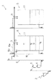
以下、カントリーエレベーター等の穀物共同乾燥調製施設の一例の構成及び該施設で用いられる循環式穀物乾燥機の構成、並びにその張込運転制御方法及び乾燥運転制御方法について説明する(図1〜図6)。図1は、前記穀物共同乾燥調製施設の要部を示している。
【0019】
前記穀物共同乾燥調製施設1には、荷受部2、粗選機3、計量機4、複数の循環式穀物乾燥機5…、籾摺り・精選部(図示せず)、サイロ(図示せず)及び排風処理装置を備えている。荷受部2は、昇降機8を介して粗選機3と連絡している。粗選機3は、該粗選機3の下方に設けた計量機4に連絡している。該計量機4は、昇降機6を介して各循環式穀物乾燥機5…の上方に横設した横搬送機7に連絡しており、該横搬送機7の各乾燥機5…の位置には、乾燥機5内に穀物を供給するためのシャッター部9をそれぞれ設けている。該シャッター部9と乾燥機5の上部とは、投入パイプ10で連絡している。
【0020】
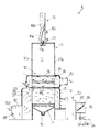
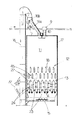
次に、循環式穀物乾燥機5の構成について図2及び図3を参照しながら説明する。図2は、一部を断面にした正面図で、また、図3は、同じく一部を断面にした側面図である。ここでは、代表して一つの乾燥機5についての説明とする。該乾燥機5は、穀物を貯留する貯留部11、穀物を予備加熱する加熱部12、穀物を熱風で乾燥させる乾燥部13、穀物を繰り出す繰り出しバルブ14…、穀物を後述する昇降機16の下部の搬送始端側に排出するスクリューコンベア15を、上方から順次重設した乾燥機本体17を備えている。
【0021】
前記加熱部12は、上下に千鳥状で横設した複数の加熱管18…を設けている。一方、前記乾燥機本体17の一側17aには、導入路19を介し、前記各加熱管18…の熱風供給側に連通した第1熱風発生装置20(以下、「加熱用バーナ部」という)を設けている。前記導入路19内には、各加熱管18…に供給される熱風の温度を検出する加熱管温度センサー21を設けている。なお、前記加熱用バーナ部20は、灯油を燃料とする加熱バーナ20bを備えると共に、加熱バーナ20bに供給する油量を調整する油量調整回路20aを備えている。また、互いに対向する下段の加熱管18,18の間には、穀物の有無を感知するレベル計45を備えている。
【0022】
前記乾燥部13は、複数の熱風路22…及び複数の排風路23…を備え、熱風路22と排風路23とを交互に並列状態で横設している。熱風路22…及び排風路23…のそれぞれの側面は、多孔板で形成し、熱風が通過するようになっており、また、隣り合う熱風路22…と排風路23…との間は、穀物流下層24…となる。熱風路22の熱風導入側の上部には、熱風の温度を検出する乾燥部温度センサー26を設けている。乾燥機本体17の他側17bには、導入路27を介し、前記各熱風路22…の熱風供給側に連通した第2熱風発生装置32(以下、「乾燥用バーナ部」という)を設けている。なお、該乾燥用バーナ部32は、灯油を燃料とする乾燥バーナ32bを備えるとともに、乾燥バーナ32bに供給する油量を調整する油量調整回路32aを備えている。
【0023】
前記加熱管18…の熱風排出側は、各加熱管18…を通過した熱風を前記導入路27に導入するべく導入路28を介して連通しており、また、該導入路28は、外気を取り入れる外気取入口29を備えている。一方、前記乾燥機本体17の一側17aには、排風装置30を設けている。該排風装置30は、導入路31を介し、各排風路23…の熱風排風側と連通している。排風装置30は、排風管33を介し、粉塵などを含んだ排風を処理する排風処理装置(図示せず)と接続している。なお、前記排風管33の排風装置30に接続する近傍内には、排風装置30の排風量を規制する排風量規制部34を設けている。該排風量規制部34は、本実施の形態では、軸35を中心として回動する風量規制板36、並びに前記軸35を回転させるモータ34a及びモータ駆動回路34bを備えている。
【0024】
前記繰り出しバルブ14は、複数設け、前記各穀物流下層21毎に対応させて設けている。また、複数の繰り出しバルブ14の下方には、前記スクリューコンベア15を設けている。
【0025】
前記各乾燥機本体17の側方には、前記昇降機16を立設している。該昇降機16は、前述のように、下部の搬送始端側が前記スクリューコンベア14の排出側と連絡しており、上部の搬送終端側が循環用パイプ16aを介して貯留部11に連絡している。前記循環用パイプ16aには、二方向、すなわち、貯留部11側又は横搬送機7側のいずれかに切換える切換えバルブ16bを備えている。該切換えバルブ16bの横搬送機7側は、パイプ16cを介して当該横搬送機7に連絡している。なお、該各昇降機16の下部には、昇降機16内の穀物を採取して当該穀物の含水率(水分値)を検出する水分計37を設けている。
【0026】
乾燥機本体17の天井内部における前記循環用パイプ16a及び投入パイプ10の下方には、該各パイプ16a,10からの穀物を飛散させる飛散盤11aを設けている。また、前記乾燥用バーナ部32の外気取入れ方向側には、外気の湿度を検出する外気湿度センサー38を備えている。
【0027】
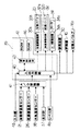
次に、前記循環式穀物乾燥機5の制御装置39の構成について、図4を参照しながら説明する。該制御装置39は、CPUを中心とした演算制御部42を中心とし、該演算制御部42に、入出力回路40、データやプログラムなどを記憶したROM47(読み出し専用記憶部)、及びデータを記憶するRAM46(記憶・読み出し用記憶部)をそれぞれ電気的に接続して構成している。前記入出力回路40は、アナログ信号をデジタル信号に変換するA/D変換器41を介して、前記加熱管温度センサー21、乾燥部温度センサー26、外気湿度センサー38及び水分計37のそれぞれと電気的に接続している。さらに、入出力回路40は、入力部43、加熱用バーナ部20、乾燥用バーナ部32、レベル計45、排風量規制部34、排風装置30、昇降機16及び切換えバルブ16bともそれぞれ電気的に接続している。なお、該入力部43は、乾燥機本体17に投入された穀物の量(張込量)、穀物の目標仕上げ水分値、張込運転や乾燥運転などの運転モードの選択指定を行うものである。
【0028】
次に、穀物共同乾燥調製施設1における循環式穀物乾燥機5の張込運転制御及び乾燥運転制御について説明する。なお、以下の説明では、1台の乾燥機5について説明し、他の乾燥機5の運転は同様のため省略する。
【0029】
はじめに、穀物共同乾燥調製施設1において荷受された穀物が循環式穀物乾燥機5に投入される作用について説明する。荷受部2に投入された穀物は、昇降機8、粗選機3、計量機4及び昇降機6を介して横搬送機7に送られる。そして、当該穀物は、投入する乾燥機5の上方まで搬送され、あらかじめ開状態にしたシャッター部9から乾燥機本体17内に投入パイプ10を介して投入される。
【0030】
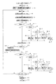
次に、循環式穀物乾燥機5の張込運転制御について、図5のフローチャートを参照しながら説明する。作業者によって前記入力部43の張込運転のボタンが押されると、この信号は、入出力回路40を介して演算制御部42に送信される。演算制御部42は、前記ROM47にあらかじめ記憶された張込運転プログラムを読み出し、該プログラムの実行を開始し、以降のステップの制御を行う(ステップ1)。
【0031】
次に、演算制御部42は、排風装置30、繰り出しバルブ14…、スクリューコンベア15、昇降機16及び飛散盤11aの作動を開始させる。これにより、乾燥機本体17に投入された穀物は、乾燥機本体17内を循環するべく、繰り出しバルブ14…から下方に繰り出された後、スクリューコンベア15、昇降機16、切換えバルブ16b及び循環用パイプ16aを介して再度乾燥機本体17内に投入される。なお、このとき、切換えバルブ16bは、演算制御部42からの信号を受け、流路が貯留部11側にされている(ステップ2)。
【0032】
次に、乾燥機本体17内に堆積する穀物が前記レベル計45まで達して該レベル計45が穀物を感知すると、レベル計45から入出力回路40を介して演算制御部42に信号が入る。演算制御部42は、この信号を受けて加熱用バーナ部20に信号を送って加熱バーナ20bを作動させる(なお、乾燥用バーナ部32は停止状態のままとする)(ステップ3)。
【0033】
次に、加熱用バーナ部20の熱風温度を加熱管温度センサー21が検出し、該検出温度データは、A/D変換器41、入出力回路40を介して演算制御部42に入る(ステップ4)。
【0034】
次に、ROM47にあらかじめ設定された張込運転のときに加熱用バーナ部20で発生させる熱風設定温度の130℃を基に、演算制御部42は、ステップ4で検出した熱風温度が130℃と「一致」しているかどうかを判定する。「一致」のときは、ステップ6を実行し、「不一致」のときは、ステップ5−1を実行する。
【0035】
前記ステップ5−1では、加熱用バーナ部20の熱風温度が130℃よりも大きいかどうかを判定する。熱風温度が130℃よりも大きい場合は、ステップ5−1−1を実行し、熱風温度が130℃よりも小さい場合は、ステップ5−2を実行する。
【0036】
前記ステップ5−1−1では、演算制御部42が、加熱バーナ20bの燃焼量を1レベル(1段階)低下させるために油量調整回路20aに信号を送り、該油量調整回路20aは、前記信号を受けて加熱バーナ20bの燃焼量を1レベルだけ低下させる。
【0037】
前記ステップ5−2では、演算制御部42が、熱風温度と130℃との温度差を求め、該温度差が10℃より大きいかどうかを判定する。温度差が10℃よりも大きい場合は、ステップ5−2−1を実行し、逆に、温度差が10℃よりも小さい場合は、ステップ5−3を実行する。
【0038】
前記ステップ5−2−1では、演算制御部42が、加熱バーナ20bの燃焼量を3レベル(3段階)上昇させるために油量調整回路20aに信号を送り、該油量調整回路20aは、前記信号を受けて加熱バーナ20bの燃焼量を3レベル上昇させる。
【0039】
前記ステップ5−3では、演算制御部42が、前記温度差が5℃より大きいかどうかを判定する。温度差が5℃よりも大きい場合は、ステップ5−3−1を実行し、逆に、温度差が5℃よりも小さい場合は、ステップ5−4を実行する。
【0040】
前記ステップ5−3−1では、演算制御部42が、加熱バーナ20bの燃焼量を2レベル(2段階)上昇させるために油量調整回路20aに信号を送り、該油量調整回路20aは、前記信号を受けて加熱バーナ20bの燃焼量を2レベル上昇させる。
【0041】
前記ステップ5−4では、演算制御部42が、加熱バーナ20bの燃焼量を1レベル(1段階)だけ上昇させるために油量調整回路20aに信号を送り、該油量調整回路20aは、前記信号を受けて加熱バーナ20bの燃焼量を1レベルだけ上昇させる。
【0042】
上記ステップ5−1−1、ステップ5−2−1、ステップ5−3−1及びステップ5−4を実行した後は、ステップ6(外気湿度の検出)を実行する。
【0043】
前記ステップ6では、外気湿度センサー38が検出した外気湿度データが、A/D変換器41、入出力回路40を介して演算制御部42に入る。
【0044】
次に、演算制御部42は、ステップ6で検出した外気湿度(相対湿度)が70%以上かどうかを判定する。70%以上のときは、ステップ8を実行し、70%未満のときはステップ9を実行する。
【0045】
前記ステップ8(外気湿度が70%以上のとき)では、演算制御部42が、排風量規制部34に信号を送って、各穀物流下層24の風量を所定の値にするべく、排風装置30の排風量を変更させる。具体的には、前記排風量規制部によって排風量を規制しない乾燥運転時の乾燥部の風量(例えば、穀物1t当たり4〜5m3/s)を基準として、外気湿度(相対湿度)データが70%以上の場合には、前記基準の風量よりも小さい第1風量(穀物1t当たり2〜2.5m3/s)とするべく、乾燥運転時の排風量100%に対して排風量を50%にする。排風量の変更は、演算制御部42が、モータ駆動回路34bに信号を送ってモータ34aを作動させて風量規制板36を回動させることにより行なわれる。
【0046】
前記ステップ9(外気湿度が70%未満のとき)では、演算制御部42が、排風量規制部34に信号を送って、乾燥部の熱風の風量を前記第1風量よりも小さい第2風量(穀物1t当たり1.2〜1.5m3/s)とするべく排風量を30%にするのがよい。排風量の変更は、ステップ8と同様である。
【0047】
風量を変更する基準とした外気湿度70%の理由は、70%未満の空気を穀物に晒すと穀物が乾燥されてしまい、当該穀物は、昇降機16によって乾燥機内に還流されるときに乾燥機内に張込まれる穀物と混ざり合い、乾燥機内で穀物は水分ムラが生じてしまうため乾燥運転のときに均一な乾燥を行うことができないことになる。よって、穀物を乾燥させないようにするために、乾燥部の熱風を前記第1風量にするべく排風装置30の排風量を変更する。一方、70%以上の空気を穀物に晒した場合には穀物は乾燥されないので、乾燥部の熱風を前記第2風量にするために排風装置30の排風量を変更する。なお、上記では、所定の風量とするために排風装置の排風量を30%や50%に規制したが、排風量は、外気湿度70%を境に乾燥部の熱風が第1風量又は第2風量となるように適宜設定するべきである。また、乾燥部の熱風の風量が小さくなるのは、排風量規制部34の規制によって排風量が低下した排風装置30の吸引作用の低下によるものである。
【0048】
次に、演算制御部42は、張込運転の停止信号が入力部43から演算制御部42に入ると、該演算制御部42は、乾燥機5を自動停止させたのち、張込運転プログラムが終了するが、停止信号が入らないときは、ステップ4に戻る(ステップ10〜12)。
【0049】
なお、ROM47にあらかじめ設定された張込運転のときに加熱用バーナ部20で発生させる熱風設定温度については、上述の130℃に限ることなく適宜設定すればよい。また、穀物温度を検出する穀物温度センサーを加熱部と乾燥部との間に設けて、穀温が所定温度になると加熱用バーナ部20を停止させ、穀温が低い場合は、前記加熱用バーナ部20を点火させるようにしてもよい。
【0050】
以上のステップにより、加熱用バーナ部20からの130℃の温度に維持された熱風は、排風装置30の吸引作用によって、各加熱管18…内を通過して各加熱管18…を一定温度に加熱した後、導入路28内で外気取入口29からの外気と混合されて温度が低下した後、導入路27に導入さる。そして、該熱風は、停止状態の乾燥用バーナ部32の外気取入口32cから導入路27に吸引される外気とも混合されて更に温度が低下する。さらに、該熱風は、各熱風路22…、各穀物流下層24…、各排風路23…、導入路31を介して排風装置30に吸引された後に、排風量規制部34によって排風量が規制排風管33で規制されて排風される。
【0051】
よって、乾燥機本体17内に投入された穀物は、各加熱管18…間を流下するとき、各加熱管18…に接触することによって受ける伝導熱と、各加熱管18…の放射熱とによって加熱され、さらに、各穀物流下層24…を流下するとき、各穀物流下層24…を通過する、低温で、かつ、外気湿度に応じた風量の熱風によって乾燥されることなく加熱される。このようにして、乾燥運転に先立って張込運転において穀物の予備加熱を行うことができる。
【0052】
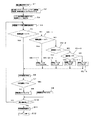
続いて、循環式穀物乾燥機5の乾燥運転制御について、図6のフローチャートを参照しながら説明する。まず、作業者は、入力部43から乾燥機本体17内に投入されて堆積した穀物量(以下、「張込量」という)や目標仕上水分値などを設定入力する。この入力信号は、入出力回路40を介して演算制御部42に入り、該演算制御部42は、この入力信号をRAM46に記憶する(ステップ1)。
【0053】
次に、作業者が前記入力部43の乾燥運転のボタンを押すと、この信号は、入出力回路40を介して演算制御部42に送信される。演算制御部42は、前記ROM47にあらかじめ記憶された乾燥運転プログラムを読み出し、該プログラムの実行を開始する。演算制御部42は、飛散盤11a、昇降機16、スクリューコンベア15、繰り出しバルブ14…、排風装置30、加熱用バーナ部20及び水分計37のそれぞれを作動開始させる。乾燥用バーナ部32は、数分後に作動開始させる。なお、前記排風量規制部34は、全開状態にし、切換えバルブ16bは、流路を乾燥機本体17側に切換える(ステップ2)。
【0054】
次に、演算制御部42は、加熱用バーナ部20の熱風設定温度TAに初期値を入力すると共に、乾燥用バーナ部32の熱風設定温度TBにも初期値を入力する(ステップ3)。
【0055】
次に、水分計37は、前記スクリューコンベア15から昇降機16に供給されて上方に搬送される穀物の水分値(含水率)を検出し、該検出値は、A/D変換器41及び入出力回路40を介して演算制御部42に取り込まれた後、RAM46に記憶される(ステップ4)。
【0056】
次に、演算制御部42は、ステップ4で検出した穀物の水分値を基にして、加熱用バーナ部20の熱風設定温度TAを下記表1に示す温度で決定する。例えば、穀物の水分値が21〜25%の範囲であれば、熱風設定温度TAを130℃とし、また、穀物の水分値が19〜21%の範囲であれば、熱風設定温度TAを120℃とする(ステップ5)。
【表1】
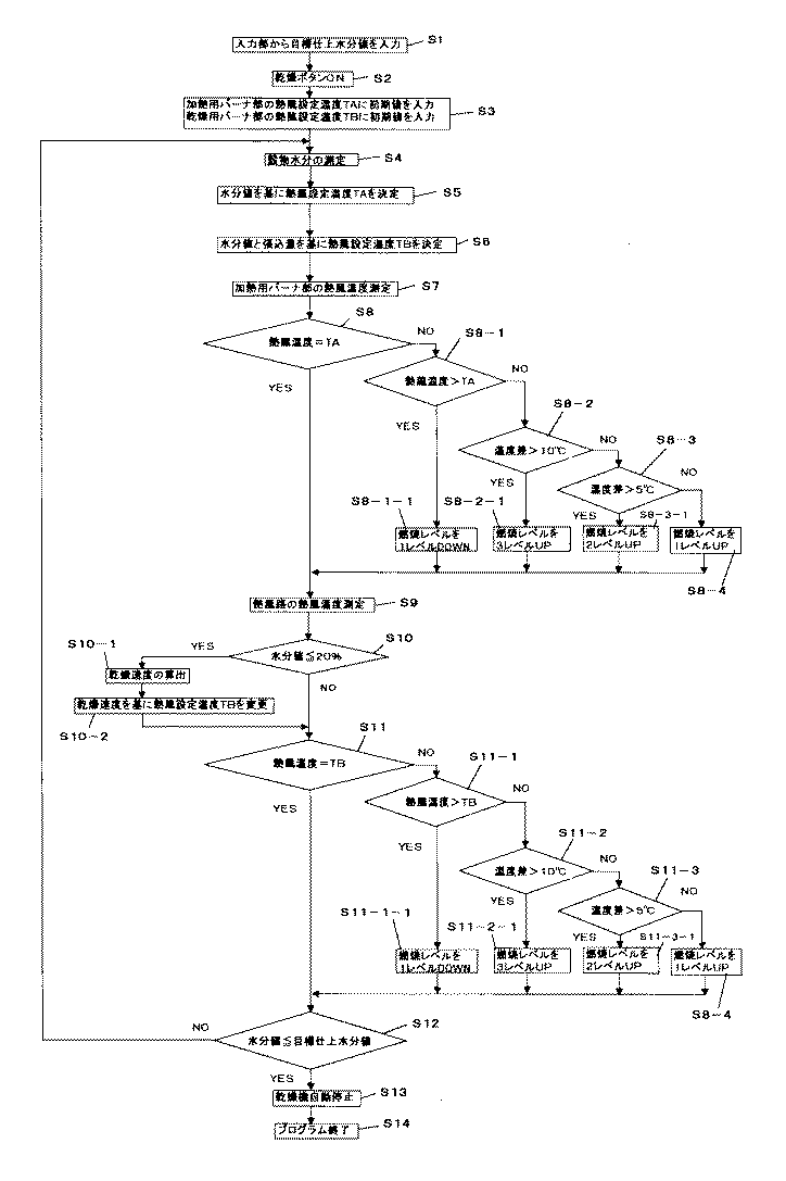
次に、演算制御部42は、ステップ4の水分値と、ステップ1でRAM46に記憶した張込量とを基に、各熱風路22…に供給する熱風設定温度TBを前記表1に示す温度に決定する。例えば、穀物の水分値が21〜25%の範囲で、かつ、張込量がレベル6であれば熱風設定温度TBを39℃とし、また、穀物の水分値が19〜21%の範囲で、かつ、張込量がレベル6であれば熱風設定温度TBを38℃とする(ステップ6)。
【0058】
次に、加熱用バーナ部20の熱風温度を加熱管温度センサー21が検出し、該検出温度データは、A/D変換器41、入出力回路40を介して演算制御部42に入る(ステップ7)。
【0059】
次に、演算制御部42は、加熱用バーナ部20の熱風温度と、先に設定した熱風設定温度TAとが「一致」するかどうかを判定する。この判定結果が、「不一致」であれば、ステップ8−1を実行し、「一致」であればステップ9を実行する(ステップ8)。
【0060】
前記ステップ8−1では、加熱用バーナ部20の熱風温度が熱風設定温度TAよりも大きいかどうかを判定する。熱風温度が熱風設定温度TAよりも大きい場合は、ステップ8−1−1を実行し、熱風温度が熱風設定温度TAよりも小さい場合は、ステップ8−2を実行する。
【0061】
前記ステップ8−1−1では、演算制御部42が、加熱バーナ20bの燃焼量を1レベル(1段階)低下させるために油量調整回路20aに信号を送り、該油量調整回路20aは、前記信号を受けて加熱バーナ20bの燃焼量を1レベルだけ低下させる。
【0062】
前記ステップ8−2では、演算制御部42が、熱風温度と熱風設定温度TAの温度差を求め、該温度差が10℃より大きいかどうかを判定する。温度差が10℃よりも大きい場合は、ステップ8−2−1を実行し、逆に、温度差が10℃よりも小さい場合は、ステップ8−3を実行する。
【0063】
前記ステップ8−2−1では、演算制御部42が、加熱バーナ20bの燃焼量を3レベル(3段階)上昇させるために油量調整回路20aに信号を送り、該油量調整回路20aは、前記信号を受けて加熱バーナ20bの燃焼量を3レベル上昇させる。
【0064】
前記ステップ8−3では、演算制御部42が、前記温度差が5℃より大きいかどうかを判定する。温度差が5℃よりも大きい場合は、ステップ8−3−1を実行し、逆に、温度差が5℃よりも小さい場合は、ステップ8−4を実行する。
【0065】
前記ステップ8−3−1では、演算制御部42が、加熱バーナ20bの燃焼量を2レベル(2段階)上昇させるために油量調整回路20aに信号を送り、該油量調整回路20aは、前記信号を受けて加熱バーナ20bの燃焼量を2レベル上昇させる。
【0066】
前記ステップ8−4では、演算制御部42が、加熱バーナ20bの燃焼量を1レベル(1段階)だけ上昇させるために油量調整回路20aに信号を送り、該油量調整回路20aは、前記信号を受けて加熱バーナ20bの燃焼量を1レベルだけ上昇させる。
【0067】
上記ステップ8−1−1、ステップ8−2−1、ステップ8−3−1及びステップ8−4を実行した後は、ステップ9(熱風路の熱風温度測定)を実行する。
【0068】
次に、ステップ9では、乾燥用バーナ部32の熱風温度を乾燥部温度センサー26が検出し、該検出温度データは、A/D変換器41、入出力回路40を介して演算制御部42に入る(ステップ9)。
【0069】
次に、演算制御部42は、ステップ4で測定した穀物の水分値が20%以下かどうかを判定する。穀物の水分値が20%以下でないときは、ステップ11を実行し、穀物の水分値が20%以下のときは、ステップ10−1を実行する(ステップ10)。
【0070】
前記ステップ10−1では、演算制御部42は、RAM46に記憶した水分値を基にして所定時間後における水分値の差を算出し、該水分値の差を前記所定時間で割り、さらに、60を掛けた値(乾燥速度値)を算出する。次に、ステップ10−2では、前記乾燥速度値がROM47にあらかじめ設定記憶された乾燥速度値の各階級のいずれに該当するかを判定する。演算制御部42は、各階級に対応してROM47にあらかじめ設定記憶された熱風路22の熱風温度補正値を基に、熱風路22の熱風設定温度TBの設定を変更する。
【0071】
次に、ステップ11では、演算制御部42が、熱風路22の熱風温度と、先に設定した熱風設定温度TBとが「一致」するかどうかを判定する。この判定結果が、「不一致」であれば、ステップ11−1を実行し、「一致」であればステップ12を実行する。
【0072】
前記ステップ11−1では、熱風路22の熱風温度が熱風設定温度TBよりも大きいかどうかを判定する。熱風温度が熱風設定温度TBよりも大きい場合は、ステップ11−1−1を実行し、熱風温度が熱風設定温度TBよりも小さい場合は、ステップ11−2を実行する。
【0073】
前記ステップ11−1−1では、演算制御部42が、乾燥バーナ32bの燃焼量を1レベル(1段階)低下させるために油量調整回路32aに信号を送り、該油量調整回路32aは、前記信号を受けて乾燥バーナ32bの燃焼量を1レベルだけ低下させる。
【0074】
前記ステップ11−2では、演算制御部42が、熱風温度と熱風設定温度TBの温度差を求め、該温度差が10℃より大きいかどうかを判定する。温度差が10℃よりも大きい場合は、ステップ11−2−1を実行し、逆に、温度差が10℃よりも小さい場合は、ステップ11−3を実行する。
【0075】
前記ステップ11−2−1では、演算制御部42が、乾燥バーナ32bの燃焼量を3レベル(3段階)上昇させるために油量調整回路32aに信号を送り、該油量調整回路32aは、前記信号を受けて乾燥バーナ32bの燃焼量を3レベル上昇させる。
【0076】
前記ステップ11−3では、演算制御部42が、前記温度差が5℃より大きいかどうかを判定する。温度差が5℃よりも大きい場合は、ステップ11−3−1を実行し、逆に、温度差が5℃よりも小さい場合は、ステップ11−4を実行する。
【0077】
前記ステップ11−3−1では、演算制御部42が、乾燥バーナ32bの燃焼量を2レベル(2段階)上昇させるために油量調整回路32aに信号を送り、該油量調整回路32aは、前記信号を受けて乾燥バーナ32bの燃焼量を2レベル上昇させる。
【0078】
前記ステップ11−4では、演算制御部42が、乾燥バーナ32bの燃焼量を1レベル(1段階)だけ上昇させるために油量調整回路32aに信号を送り、該油量調整回路32aは、前記信号を受けて乾燥バーナ32bの燃焼量を1レベルだけ上昇させる。
【0079】
上記ステップ11−1−1、ステップ11−2−1、ステップ11−3−1及びステップ11−4を実行した後は、ステップ12を実行する。
【0080】
次に、ステップ12では、演算制御部42が、ステップ4で測定した水分値がステップ1で入力した目標仕上水分値以下かどうかを判定する。水分値が目標仕上水分値以下であればステップ13を実行し、水分値が目標仕上水分値以下でないときは、ステップ4に戻る。
【0081】
ステップ13〜14では、演算制御部42が乾燥機5を自動停止させたのち、乾燥運転プログラムが終了する。
【0082】
以上のステップ1〜ステップ14の乾燥運転制御により、本願の循環式穀物乾燥機5によれば、加熱部12では、各加熱管18…に供給する熱風を穀物の水分値に応じた温度に維持し、該温度の熱風によって加熱された各加熱部18…によって予備加熱を行うことができ、一方、乾燥部13では、各熱風路22…に供給する熱風を穀物の水分値及び張込量に応じた温度に維持し、かつ、該温度の熱風(乾燥風)によって乾燥することができる。よって、穀物乾燥時間を、従来よりも短縮することができる。
【0083】
【発明の効果】
本発明の第1の技術的課題を解決するために、
請求項1による循環式穀物乾燥機によれば、
制御装置は、加熱用バーナ部を作動させる一方、乾燥用バーナ部を停止させる。そして、制御装置は、外気湿度検出手段の外気湿度に応じて排風量規制部に信号を送り、該排風量規制部の作動によって排風装置からの排風量を変更させて乾燥部の風量を変更する。これによって、各加熱管は、加熱用バーナ部の熱風によって加熱され、前記熱風は停止状態の乾燥用バーナ部を介して導入される外気と混じり合って低温熱風となって乾燥部に導入される。そして、外気湿度に応じて作動する排風量規制部によって排風装置の排風量が変更するため、乾燥部に導入される低温熱風の風量は、外気湿度に応じて変更される。よって、乾燥機内に投入された穀物は、各加熱管の間を流下するとき、各加熱管に接触することによって受ける伝導熱と、各加熱管の放射熱とによって加熱され、さらに、各穀物流下層を流下するとき、各穀物流下層を通過する、低温で、かつ、外気湿度に応じた風量の熱風に晒されるので、乾燥されることなく加熱される。よって、乾燥運転に先立ち張込運転において穀物の予備加熱を行うことができる。
【0084】
本発明の第2の技術的課題を解決するために、
請求項4による循環式穀物乾燥機によれば、
制御装置は、各加熱管内に供給する熱風が穀物水分値に応じた温度になるように、加熱管用熱風温度検出手段の検出温度値を基にしながら加熱用バーナ部を制御するので、各加熱管の加熱温度は、穀物水分値に応じた熱風温度となる。一方、制御装置は、乾燥部内に供給される熱風が穀物水分値及び張込量に応じた適温になるように乾燥部用熱風温度検出手段の検出温度値を基にしながら乾燥用バーナ部を制御するので、乾燥部内に導入される熱風は、各加熱管を通過した熱風が外気取入口からの外気と混合されると共に、乾燥用バーナ部からの熱風とも混合され、穀物水分値及び張込量に応じた適温になる。なお、各加熱管の加熱温度及び乾燥部の熱風温度は、胴割れなどによる穀物の品質低下を生じさせないものとする。よって、乾燥機内に張込まれた穀物は、穀物水分値に応じ、すなわち、乾燥が進行するにつれて変化する穀物水分値に対応した温度に加熱された各加熱管によって予備加熱され、この予備加熱された穀物は、乾燥部に流下し、該乾燥部で、穀物水分値及び張込量に応じた温度の熱風が供給されるので、効率的な乾燥が行われることにより従来よりも乾燥時間が短縮できる。
【図面の簡単な説明】
【図1】 本発明の穀物共同乾燥調製施設の一例の要部を示す図である。
【図2】 本発明の循環式穀物乾燥機の一部を断面にした正面図である。
【図3】 本発明の循環式穀物乾燥機の一部を断面にした側面図である。
【図4】 本発明の循環式穀物乾燥機を制御する制御ブロック図である。
【図5】 本発明の循環式穀物乾燥機の張込運転制御のフローチャート図である。
【図6】 本発明の循環式穀物乾燥機の乾燥運転制御のフローチャート図である。
【符号の説明】
1 穀物共同乾燥調製施設
2 荷受部
3 粗選機
4 計量機
5 循環式穀物乾燥機
6 昇降機
7 横搬送機
8 昇降機
9 シャッター部
10 投入パイプ
11 貯留部
12 加熱部
13 乾燥部
14 繰り出しバルブ
15 スクリューコンベア
16 昇降機
16a 循環用パイプ
16b 切換えバルブ
16c パイプ
17 乾燥機本体
17a 一側
17b 他側
18 加熱管
19 導入路
20 第1熱風発生装置(加熱用バーナ部)
20a 油量調整回路
20b 加熱バーナ
21 加熱管温度センサー
22 熱風路
23 排風路
24 穀物流下層
26 乾燥部温度センサー
27 導入路
28 導入路
29 外気取入口
30 排風装置
31 導入路
32 第2熱風発生装置(乾燥用バーナ部)
32a 油量調整回路
32b 乾燥バーナ
32c 外気取入口
33 排風管
34 排風量規制部
34a モータ
34b モータ駆動回路
35 軸
36 風量規制板
37 水分計
38 外気湿度センサー
39 制御装置
40 入出力回路
41 A/D変換器
42 演算制御部
43 入力部
45 レベル計
46 RAM
47 ROM [0001]
BACKGROUND OF THE INVENTION
The present invention relates to a circulation type grain dryer for drying grains such as straw and wheat.
[0002]
[Prior art]
Conventionally, in circulation type grain dryers, in order to shorten the drying time, the grain temperature (hereinafter referred to as “grain temperature”) is increased in advance, separately from the drying section that supplies hot air to the grains and dries them. Some are equipped with a heating section.
[0003]
For example, a circulation type grain dryer disclosed in Japanese Patent Application Laid-Open No. Sho 62-9174 is provided with a storage part for temporarily storing grains and a plurality of heating pipes through which hot air generated by one burner passes to perform preheating of grains. And a drying unit for introducing hot air in each of the heating tubes and drying the grains with hot air are sequentially stacked from above.
[0004]
JP-A-2-309177 discloses a storage unit, an upper drying unit for preheating grains provided with a burner, and a lower drying unit for drying grains similarly provided with a burner, which are sequentially stacked from above. Is.
[0005]
Furthermore, the thing of Japanese Patent Application No. 10-265486 filed by the applicant of the present application includes a storage part, a heating part that includes a plurality of heating pipes through which hot air generated by the heating means passes, and that preheats the grain, and A drying section that dries the grains with hot air generated by a heating means different from the heating means is sequentially stacked from above.
[0006]
[Problems to be solved by the invention]
Each of the conventional circulation type grain dryers has the following problems.
First, in Japanese Patent Laid-Open No. Sho 62-9174, hot air generated by one burner passes through each heating pipe to heat the heating pipe, and after the temperature is deprived by the heating pipe, the temperature drops. In order to introduce hot air having a predetermined temperature into the drying unit, the hot air for heating the heating tube is set to a temperature corresponding to the predetermined temperature. Therefore, there is a concern that the heating tube cannot be heated sufficiently, or that the heating temperature of the heating tube and the hot air temperature of the drying section cannot be controlled, and the drying efficiency is poor.
[0007]
Next, JP-A-2-309177 discloses a method in which hot air having a small amount of high temperature is supplied to a grain in the upper drying section to raise the grain temperature, and then the hot air having a large amount of low temperature in the lower drying section. However, since the grains are exposed (exposed) to hot air for a long time in the upper drying section and the lower drying section, there is a concern that the quality of the grains may be deteriorated. In addition, the upper drying section and the lower drying section are equipped with separate burners, and the efficiency of drying is improved due to concerns about the above-mentioned deterioration in grain quality and the fact that hot air from the upper drying section is not used for the lower drying section. Is desired.
[0008]
Further, in Japanese Patent Application No. 10-265486, the heating unit and the drying unit are each provided with heating means, and the grain is preheated by a heating tube heated to a predetermined constant temperature by the heating means for the heating unit. After that, hot air having a grain temperature not higher than the grain temperature heated by the heating unit, which is generated by a heating means different from the heating means, is supplied to the grain, and the grain is efficiently dried while preventing deterioration of grain quality. However, in the dryer of the publication, the drying operation proceeds only by setting the heating temperature of the heating tube to a predetermined constant temperature and the hot air supplied to the drying unit at a temperature equal to or lower than the grain temperature heated by the heating unit. However, the heating temperature of the heating tube and the temperature of the hot air supplied to the drying section were not controlled to the optimum temperatures in consideration of the grain moisture value that changes with the temperature. In addition, since the heating unit and the drying unit are provided with heating means separately, and the hot air from the heating unit is exhausted out of the dryer as it is, improvement of the drying efficiency is desired.
[0009]
As described above, in view of the problems of the conventional circulation type grain dryer, the inventor of the present application, in order to further shorten the drying time and improve the drying efficiency than the conventional one, the first technical problem of the present invention is: It is intended to provide a circulation type grain dryer capable of preheating grain for drying from the time of the tension operation, and the second technical problem of the present invention is to heat the grain during the drying operation. A circulation type grain dryer that shortens the drying time by individually controlling the hot air temperature of the heating unit and the drying unit according to the grain moisture value while utilizing the hot air of the part.
[0010]
[Means for Solving the Problems]
In order to solve the first technical problem of the present invention, the means of
A circulating grain dryer according to
Burner section for heating( 20 )Multiple heating tubes through which hot air from( 18 )Heating part to heat the grain with( 12 )When,
The heating unit( 12 )Below each heating tube( 18 )The hot air that passed through the burner section for drying( 32 )Drying section for drying grain by supplying with hot air from( 13 )When,
The drying unit( 13 )Exhaust device that sucks out hot air from the dryer and exhausts it outside the dryer( 30 )When,
The exhaust device( 30 )Exhaust air volume control unit that regulates the exhaust air volume( 34 )When,
Outside air humidity detecting means for detecting outside air humidity( 38 )When,
The heating burner( 20 ), Drying burner( 32 ), Exhaust air volume control department( 34 )And outside air humidity detection means( 38 )Control device electrically connected to each of the( 39 )When,
A circulating grain dryer comprising:
The control device( 39 )During heating operation, the burner section for heating( 20 )And burner section for drying( 32 )And the outside air humidity detection means( 38 )The exhaust air flow restriction unit according to the detected outside air humidity( 34 )Operate the exhaust device( 30 )To change the amount of exhaust air
The technical means is taken.
[0011]
The control device operates the heating burner unit (first hot air generator) and stops the drying burner unit (second hot air generator). Then, the control device sends a signal to the exhaust air amount regulating unit according to the outside air humidity of the outside air humidity detecting means, and changes the air amount of the drying unit by changing the exhaust air amount from the exhaust device by the operation of the exhaust air amount regulating unit. To do. Thereby, each heating tube is heated by the hot air of the heating burner unit, and the hot air is mixed with the outside air introduced through the drying burner unit in a stopped state to be introduced into the drying unit as low temperature hot air. . And since the exhaust air amount of an exhaust apparatus changes with the exhaust air amount control part which operate | moves according to external air humidity, the air volume of the low temperature hot air introduce | transduced into a drying part is changed according to external air humidity. Therefore, when the grain put into the dryer flows down between the heating tubes, it is heated by the conduction heat received by contacting each heating tube and the radiant heat of each heating tube. When flowing down the lower layer, it is heated without being dried because it is exposed to hot air having a low temperature and flowing according to the outside air humidity that passes through each grain lower layer. Therefore, grain preheating can be performed in the tension operation prior to the drying operation.
In addition, when the grain is dried during the tension operation,LaterMixing with the grains put into the dryer causes moisture unevenness in the grains in the dryer, which is not preferable because the drying unevenness of the grains is caused by subsequent drying operation.
[0012]
A circulation type grain dryer according to
The drying unit( 13 )The air volume of the exhaust air volume regulating section( 34 )Drying section during drying operation that does not regulate exhaust air volume by( 13 )When the outside air humidity detection value is equal to or higher than a predetermined humidity, the first air volume is smaller than the reference, and when the outside air humidity detection value is lower than the predetermined humidity, the first air volume is further increased. The technical means of changing the exhaust air volume of an exhaust apparatus by operating the said exhaust air flow control part so that it may become small 2nd air volume is taken.
[0013]
Therefore, based on the air volume of the drying section during the drying operation in which the exhaust air volume regulating section does not regulate the exhaust air volume, the air volume of the drying section is a first air volume smaller than the reference when the air volume is equal to or higher than a predetermined humidity, In some cases, since the operation is performed with a second air volume smaller than the first air volume, the grain in the drying section is exposed to a low-temperature hot air with an air volume corresponding to the outside air humidity. Therefore, the grain is heated without being dried in the drying section.
[0014]
A circulation type grain dryer according to
The predetermined humidity is 70%.
The technical means is taken.
[0015]
Accordingly, the air volume in the drying section is changed with the outside air humidity of 70% as a boundary, so that the grain is heated without being dried in the drying section.
[0016]
In order to solve the second technical problem of the present invention, the means of claim 4 is taken.
A circulation type grain dryer according to claim 4 is:
Burner section for heating( 20 )Multiple heating tubes through which hot air from( 18 )Heating part to heat the grain with( 12 )When,
The heating unit( 12 )Below each heating tube( 18 )The hot air that passed through the burner section for drying( 20 )Drying section for drying grain by supplying with hot air from( 13 )When,
The drying unit( 13 )Exhaust device that sucks hot air and exhausts it outside the dryer( 30 )When,
Drying section( 13 )Hot air temperature detecting means for drying section for detecting hot air temperature supplied inside( 26 )When,
Heating tube( 18 )Hot air temperature detecting means for detecting the temperature of hot air supplied to the inside( twenty one )When,
Moisture detection means for detecting the moisture value of grains( 37 )When,
Input section for inputting the amount of extension( 43 )When,
The heating burner( 20 ), Drying burner( 32 ), Hot air temperature detection means for drying section( 26 ), Hot air temperature detection means for heating tubes( twenty one ), Moisture detection means( 37 )And input section( 43 )Control device electrically connected to each of the( 39 )When,
A circulating grain dryer comprising:
The control device( 39 )During dry operationAboveEach heating tube( 18 )Hot air temperature supplied insideIs said moisture detection means ( 37 )byAccording to grain moisture detection valueThe heating tube hot air temperature detecting means ( twenty one ) Based on the detected temperature valueBurner section for heating( 20 )ControlWhenboth,AboveDrying section( 13 )Supplied withinYouHot air temperatureSaidGrain moisture detection value andThe input section ( 43 )Depending on the amount of tensionThe drying section hot air temperature detecting means ( 26 ) Based on the detected temperature valueBurner section for drying( 32 )To control the
The technical means is taken.
[0017]
The control device controls the heating burner unit based on the detected temperature value of the hot air temperature detecting means for the heating tube so that the hot air supplied into each heating tube has a temperature corresponding to the grain moisture value. The heating temperature is a hot air temperature according to the grain moisture value. On the other hand, the control device controls the drying burner unit based on the detected temperature value of the hot air temperature detecting means for the drying unit so that the hot air supplied into the drying unit becomes a temperature corresponding to the moisture content of the grain and the amount of tension. Therefore, the hot air introduced into the drying section is mixed with the hot air that has passed through each heating pipe and the outside air from the outside air intake, and is also mixed with the hot air from the drying burner section. It becomes the temperature according to. It should be noted that the heating temperature of each heating tube and the hot air temperature of the drying section shall not cause a drop in grain quality due to shell cracks or the like. Therefore, the grain stretched in the dryer is preheated by each heating tube heated to a temperature corresponding to the grain moisture value that changes according to the grain moisture value, that is, as drying progresses. The cereals flow down to the drying section, where hot air at a temperature according to the moisture content of the grains and the amount of tension is supplied. it can.
[0018]
DETAILED DESCRIPTION OF THE INVENTION
Hereinafter, a configuration of an example of a grain joint drying preparation facility such as a country elevator, a configuration of a circulation type grain dryer used in the facility, a tension operation control method, and a drying operation control method will be described (FIGS. 1 to 6). ). FIG. 1 shows a main part of the grain co-drying preparation facility.
[0019]
The grain common
[0020]
Next, the configuration of the circulation
[0021]
The
[0022]
The drying
[0023]
The hot air discharge side of the
[0024]
A plurality of
[0025]
The
[0026]
Below the
[0027]
Next, the configuration of the
[0028]
Next, the tension operation control and the drying operation control of the circulation
[0029]
First, the operation in which the grains received at the grain joint
[0030]
Next, the tension operation control of the circulation
[0031]
Next, the
[0032]
Next, when the grain accumulated in the dryer
[0033]
Next, the hot air temperature of the
[0034]
Next, ROM47On the basis of the hot
[0035]
In said step 5-1, it is determined whether the hot air temperature of the
[0036]
In step 5-1-1, the
[0037]
In Step 5-2, the
[0038]
In step 5-2-1, the
[0039]
In step 5-3, the
[0040]
In step 5-3-1, the
[0041]
In Step 5-4, the
[0042]
After executing Step 5-1-1, Step 5-2-1, Step 5-3-1 and Step 5-4, Step 6 (Detection of outside air humidity) is executed.
[0043]
In step 6, the outside air humidity data detected by the outside
[0044]
Next, the
[0045]
In the step 8 (when the outside air humidity is 70% or more), the
[0046]
In the step 9 (when the outside air humidity is less than 70%), the
[0047]
The reason for the outside air humidity of 70% as a reference for changing the air volume is that when less than 70% air is exposed to the grain, the grain is dried, and when the grain is returned to the dryer by the
[0048]
Next, when the stop signal of the tension operation is entered from the
[0049]
ROM47The hot air set temperature generated by the
[0050]
Through the above steps, the hot air maintained at a temperature of 130 ° C. from the
[0051]
Therefore, when the grain put into the dryer
[0052]
Next, the drying operation control of the circulating
[0053]
Next, when an operator presses the button for drying operation of the
[0054]
Next, the
[0055]
Next, the
[0056]
Next, the
[Table 1]
Next, the
[0058]
Next, the heating
[0059]
Next, the
[0060]
In Step 8-1, it is determined whether the hot air temperature of the
[0061]
In Step 8-1-1, the
[0062]
In step 8-2, the
[0063]
In step 8-2-1, the
[0064]
In Step 8-3, the
[0065]
In Step 8-3-1, the
[0066]
In step 8-4, the
[0067]
After executing Step 8-1-1, Step 8-2-1, Step 8-3-1 and Step 8-4, Step 9 (Measurement of hot air temperature of hot air path) is executed.
[0068]
Next, in
[0069]
Next, the
[0070]
In step 10-1, the
[0071]
Next, in
[0072]
In Step 11-1, it is determined whether or not the hot air temperature in the
[0073]
In step 11-1-1, the
[0074]
In step 11-2, the
[0075]
In the step 11-2-1, the
[0076]
In Step 11-3, the
[0077]
In Step 11-3-1, the
[0078]
In step 11-4, the
[0079]
After executing Step 11-1-1, Step 11-2-1, Step 11-3-1 and Step 11-4,
[0080]
Next, in
[0081]
In
[0082]
According to the drying operation control in
[0083]
【The invention's effect】
In order to solve the first technical problem of the present invention,
According to the circulating grain dryer according to
The control device operates the heating burner unit while stopping the drying burner unit. Then, the control device sends a signal to the exhaust air amount regulating unit according to the outside air humidity of the outside air humidity detecting means, and changes the air amount of the drying unit by changing the exhaust air amount from the exhaust device by the operation of the exhaust air amount regulating unit. To do. Thereby, each heating tube is heated by the hot air of the heating burner unit, and the hot air is mixed with the outside air introduced through the drying burner unit in a stopped state to be introduced into the drying unit as low temperature hot air. . And since the exhaust air amount of an exhaust apparatus changes with the exhaust air amount control part which operate | moves according to external air humidity, the air volume of the low temperature hot air introduce | transduced into a drying part is changed according to external air humidity. Therefore, when the grain put into the dryer flows down between the heating tubes, it is heated by the conduction heat received by contacting each heating tube and the radiant heat of each heating tube. When flowing down the lower layer, it is heated without being dried because it is exposed to hot air having a low temperature and flowing according to the outside air humidity that passes through each grain lower layer. Therefore, grain preheating can be performed in the tension operation prior to the drying operation.
[0084]
In order to solve the second technical problem of the present invention,
According to the circulation type grain dryer according to claim 4,
The control device controls the heating burner unit based on the detected temperature value of the hot air temperature detecting means for the heating tube so that the hot air supplied into each heating tube has a temperature corresponding to the grain moisture value. The heating temperature is a hot air temperature according to the grain moisture value. On the other hand, the control device is based on the detected temperature value of the hot air temperature detecting means for the drying unit so that the hot air supplied into the drying unit has an appropriate temperature corresponding to the grain moisture value and the amount of tension.Burner section for dryingTherefore, the hot air introduced into the drying section is mixed with the hot air that has passed through each heating pipe and the outside air from the outside air intake, and is also mixed with the hot air from the drying burner section. It becomes the appropriate temperature according to the amount. It should be noted that the heating temperature of each heating tube and the hot air temperature of the drying section shall not cause a drop in grain quality due to shell cracks or the like. Therefore, the grain stretched in the dryer is preheated by each heating tube heated to a temperature corresponding to the grain moisture value that changes according to the grain moisture value, that is, as drying progresses. The cereals flow down to the drying section, where hot air at a temperature according to the moisture content of the grains and the amount of tension is supplied. it can.
[Brief description of the drawings]
FIG. 1 is a diagram showing a main part of an example of a grain co-drying preparation facility of the present invention.
FIG. 2 is a front view, partly in section, of a circulating grain dryer according to the present invention.
FIG. 3 is a side view of a section of a circulating grain dryer according to the present invention.
FIG. 4 is a control block diagram for controlling the circulating grain dryer according to the present invention.
FIG. 5 is a flowchart of the tension operation control of the circulation type grain dryer according to the present invention.
FIG. 6 is a flowchart of drying operation control of the circulation type grain dryer of the present invention.
[Explanation of symbols]
1 Grain joint drying preparation facility
2 Receiving part
3 Coarse selector
4 Weighing machine
5 Circulating grain dryer
6 Elevator
7 Horizontal conveyor
8 Elevator
9 Shutter part
10 Input pipe
11 Reservoir
12 Heating part
13 Drying section
14 Feeding valve
15 Screw conveyor
16 Elevator
16a Circulation pipe
16b switching valve
16c pipe
17 Dryer body
17a One side
17b The other side
18 Heating tube
19 Introduction
20 1st hot air generator (heating burner part)
20a Oil amount adjustment circuit
20b Heating burner
21 Heating tube temperature sensor
22 Hot air passage
23 Exhaust channel
24 Grain underflow
26 Drying part temperature sensor
27 Introduction route
28 Introduction route
29 Outside air intake
30 Air exhaust device
31 Introduction route
32 Second hot air generator (drying burner)
32a Oil amount adjustment circuit
32b Dry burner
32c Outside air intake
33 Exhaust pipe
34 Exhaust Volume Control Department
34a motor
34b Motor drive circuit
35 axes
36 Air volume control board
37 moisture meter
38 Outside air humidity sensor
39 Control device
40 I / O circuit
41 A / D converter
42 Operation control unit
43Input section
45 level meter
46 RAM
47 ROM
Claims (4)
該加熱部( 12 )の下方に、前記各加熱管( 18 )を通過した熱風を乾燥用バーナ部( 32 )からの熱風と共に供給して穀物を乾燥する乾燥部( 13 )と、
前記乾燥部( 13 )の熱風を吸引して乾燥機外に排風する排風装置( 30 )と、
該排風装置( 30 )の排風量を規制する排風量規制部( 34 )と、
外気湿度を検出する外気湿度検出手段( 38 )と、
前記加熱用バーナ部( 20 )、乾燥用バーナ部( 32 )、排風量規制部( 34 )及び外気湿度検出手段( 38 )のそれぞれに電気的に接続した制御装置( 39 )と、
を有する循環式穀物乾燥機であって、
前記制御装置( 39 )は、張込運転のときに、加熱用バーナ部( 20 )を作動させると共に乾燥用バーナ部( 32 )を停止させ、また、外気湿度検出手段( 38 )の外気湿度検出値に応じて前記排風量規制部( 34 )を作動させて排風装置( 30 )の排風量を変更させることを特徴とする循環式穀物乾燥機。A heating section ( 12 ) for heating the grain with a plurality of heating pipes ( 18 ) through which hot air from the heating burner section ( 20 ) passes;
Below the heating unit ( 12 ) , a drying unit ( 13 ) that supplies hot air that has passed through each heating pipe ( 18 ) together with hot air from the drying burner unit ( 32 ) to dry the grains,
An exhaust device ( 30 ) for sucking hot air from the drying section ( 13 ) and exhausting it outside the dryer;
An exhaust air flow restricting section ( 34 ) for controlling the exhaust air flow of the exhaust air exhaust device ( 30 ) ;
Outside air humidity detecting means ( 38 ) for detecting outside air humidity;
A control device ( 39 ) electrically connected to each of the heating burner section ( 20 ) , the drying burner section ( 32 ) , the exhaust air volume regulating section ( 34 ), and the outside air humidity detecting means ( 38 ) ;
A circulating grain dryer comprising:
Wherein the control unit (39), when the Chokomi operation, the drying burner unit actuates the heating burner unit (20) to (32) is stopped, also the outside air humidity detecting the outside air humidity detecting means (38) A circulation type grain dryer characterized by operating the exhaust air amount regulating part ( 34 ) according to the value to change the exhaust air amount of the air exhaust device ( 30 ) .
該加熱部( 12 )の下方に、前記各加熱管( 18 )を通過した熱風を乾燥用バーナ部( 20 )からの熱風と共に供給して穀物を乾燥する乾燥部( 13 )と、
前記乾燥部( 13 )の熱風を吸引して乾燥機外に排風する排風装置( 30 )と、
乾燥部( 13 )内に供給される熱風温度を検出する乾燥部用熱風温度検出手段( 26 )と、
加熱管( 18 )内に供給される熱風温度を検出する加熱管用熱風温度検出手段( 21 )と、
穀物の水分値を検出する水分検出手段( 37 )と、
張込量を入力する入力部( 43 )と、
前記加熱用バーナ部( 20 )、乾燥用バーナ部( 32 )、乾燥部用熱風温度検出手段( 26 )、加熱管用熱風温度検出手段( 21 )、水分検出手段( 37 )及び入力部( 43 )のそれぞれと電気的に接続した制御装置( 39 )と、
を有する循環式穀物乾燥機であって、
前記制御装置( 39 )は、乾燥運転のときに、前記各加熱管( 18 )内に供給する熱風温度が前記水分検出手段( 37 )による穀物水分検出値に応じた所定の温度となるように前記加熱管用熱風温度検出手段( 21 )の検出温度値に基づいて加熱用バーナ部( 20 )を制御すると共に、前記乾燥部( 13 )内に供給する熱風温度が前記穀物水分検出値及び前記入力部( 43 )から入力された張込量に応じた所定の温度となるように前記乾燥部用熱風温度検出手段( 26 )の検出温度値に基づいて乾燥用バーナ部( 32 )を制御することを特徴とする循環式穀物乾燥機。A heating section ( 12 ) for heating the grain with a plurality of heating pipes ( 18 ) through which hot air from the heating burner section ( 20 ) passes;
Below the heating unit ( 12 ) , a drying unit ( 13 ) that supplies hot air that has passed through each heating pipe ( 18 ) together with hot air from the drying burner unit ( 20 ) to dry the grains,
An exhaust device ( 30 ) for sucking hot air from the drying section ( 13 ) and exhausting it outside the dryer;
A hot air temperature detecting means ( 26 ) for the drying unit for detecting the temperature of the hot air supplied into the drying unit ( 13 ) ;
A hot air temperature detecting means ( 21 ) for detecting the temperature of the hot air supplied into the heating tube ( 18 ) ;
Moisture detection means ( 37 ) for detecting the moisture value of the grain;
Input part ( 43 ) for inputting the amount of extension,
The heating burner section ( 20 ) , the drying burner section ( 32 ) , the hot air temperature detecting means for the drying section ( 26 ) , the hot air temperature detecting means for the heating pipe ( 21 ) , the moisture detecting means ( 37 ) and the input section ( 43 ) A control device ( 39 ) electrically connected to each of the
A circulating grain dryer comprising:
Wherein the control device (39) is dry when operating such that said hot air temperature supplied to each heating tube (18) is the moisture detecting means predetermined temperature depending on the grain moisture detection value by (37) the heating burner unit based on the detected temperature value of the hot air temperature detecting means for heating pipes (21) (20) both by controlling the said drying unit (13) the grain moisture value detected hot wind temperature you supplied into and The drying burner unit ( 32 ) is controlled based on the detected temperature value of the drying unit hot air temperature detecting means ( 26 ) so as to be a predetermined temperature corresponding to the amount of tension input from the input unit ( 43 ). A circulation type grain dryer characterized by
Priority Applications (7)
| Application Number | Priority Date | Filing Date | Title |
|---|---|---|---|
| JP23764399A JP4172002B2 (en) | 1999-08-24 | 1999-08-24 | Circulating grain dryer |
| US09/640,372 US6318000B1 (en) | 1999-08-24 | 2000-08-17 | Circulating type grain drying machine |
| TW089116796A TWI229181B (en) | 1999-08-24 | 2000-08-18 | Circulating type grain drying machine |
| BR0003738-9A BR0003738A (en) | 1999-08-24 | 2000-08-22 | Circulation type grain drying machine |
| AU53559/00A AU764935B2 (en) | 1999-08-24 | 2000-08-23 | Circulating type grain drying machine |
| CN00126023A CN1123755C (en) | 1999-08-24 | 2000-08-24 | Cirulation type grain dryer |
| KR10-2000-0049161A KR100430446B1 (en) | 1999-08-24 | 2000-08-24 | Circulating type grain drying machine |
Applications Claiming Priority (1)
| Application Number | Priority Date | Filing Date | Title |
|---|---|---|---|
| JP23764399A JP4172002B2 (en) | 1999-08-24 | 1999-08-24 | Circulating grain dryer |
Publications (3)
| Publication Number | Publication Date |
|---|---|
| JP2001066065A JP2001066065A (en) | 2001-03-16 |
| JP2001066065A5 JP2001066065A5 (en) | 2006-10-05 |
| JP4172002B2 true JP4172002B2 (en) | 2008-10-29 |
Family
ID=17018374
Family Applications (1)
| Application Number | Title | Priority Date | Filing Date |
|---|---|---|---|
| JP23764399A Expired - Fee Related JP4172002B2 (en) | 1999-08-24 | 1999-08-24 | Circulating grain dryer |
Country Status (7)
| Country | Link |
|---|---|
| US (1) | US6318000B1 (en) |
| JP (1) | JP4172002B2 (en) |
| KR (1) | KR100430446B1 (en) |
| CN (1) | CN1123755C (en) |
| AU (1) | AU764935B2 (en) |
| BR (1) | BR0003738A (en) |
| TW (1) | TWI229181B (en) |
Families Citing this family (36)
| Publication number | Priority date | Publication date | Assignee | Title |
|---|---|---|---|---|
| DE10042135A1 (en) * | 2000-08-28 | 2002-03-14 | Buehler Ag | Process and plant for conveying rice |
| US6637982B2 (en) * | 2002-01-14 | 2003-10-28 | Hitachi Plant Engineering & Construction Co., Ltd. | Gas transportation method for grain |
| AU782742B2 (en) * | 2002-01-17 | 2005-08-25 | Hitachi Plant Technologies, Ltd. | Gas transportation method for grain |
| US6834443B2 (en) * | 2003-02-11 | 2004-12-28 | Ctb Ip, Inc. | Full heat moving target grain drying system |
| JP5125419B2 (en) * | 2007-10-31 | 2013-01-23 | 井関農機株式会社 | Drying equipment |
| KR100968966B1 (en) | 2008-04-23 | 2010-07-14 | 한성공업 주식회사 | Rice circulating concurrent-flow dryer |
| US8479408B2 (en) | 2009-03-13 | 2013-07-09 | Noble M. Salisbury | Retrofit grain dryer moisture controller |
| WO2010106611A1 (en) * | 2009-03-16 | 2010-09-23 | Ando Toshiharu | Method of producing nutritionally enriched rice |
| CH700876A1 (en) * | 2009-04-24 | 2010-10-29 | Buehler Ag | A method of producing rice. |
| FI124016B (en) * | 2009-10-26 | 2014-01-31 | Vapo Oy | Process for heating drying air used in a biomass dryer by means of an intermediate circuit and using a water-glycol mixture or similar frost-free intermediate circuit liquid to heat drying air used in a biomass dryer |
| JP5716740B2 (en) * | 2010-04-22 | 2015-05-13 | 株式会社サタケ | Grain drying equipment |
| TW201241383A (en) * | 2011-04-01 | 2012-10-16 | Suncue Co Ltd | Thermal energy supply control method for multiple dryers and system thereof |
| CN103890516B (en) * | 2011-10-21 | 2016-01-13 | 株式会社佐竹 | Grain drying equipment |
| CN104160232B (en) * | 2012-03-06 | 2016-02-17 | 株式会社佐竹 | Grain drying method |
| CN102679716A (en) * | 2012-05-31 | 2012-09-19 | 苏州市金翔钛设备有限公司 | Grain drier for realizing remote control |
| CN103399563B (en) * | 2013-08-16 | 2016-06-15 | 安徽科技学院 | Drying tower controller |
| CN103438693B (en) * | 2013-08-30 | 2015-03-25 | 中国农业大学 | Automatic control system of gas jet impact drying machine |
| CN103528360B (en) * | 2013-10-17 | 2015-08-26 | 中国中轻国际工程有限公司 | A kind of control method being applicable to barley drying plant |
| AT514801B1 (en) * | 2013-11-22 | 2015-04-15 | Heutrocknung Sr Gmbh | Method for drying of drying material |
| CN103808118B (en) * | 2013-12-03 | 2015-10-28 | 宁波德锐电气有限公司 | Drying machine energy conserving system |
| CN104034146A (en) * | 2014-03-31 | 2014-09-10 | 绍兴文理学院 | Drying tower |
| CN105285090A (en) * | 2014-07-23 | 2016-02-03 | 唐东亭 | Continuous vacuum far-infrared low-temperature grain drying machine |
| US9950872B2 (en) | 2015-11-30 | 2018-04-24 | Superior Manufacturing LLC | Bin sweep auger unplugging system |
| CN105758169A (en) * | 2016-03-11 | 2016-07-13 | 安徽新生力生物科技有限公司 | Automatic control system for drying grains |
| CN105737590A (en) * | 2016-03-11 | 2016-07-06 | 安徽新生力生物科技有限公司 | Monitoring system of grain dryer |
| CN105627731A (en) * | 2016-03-11 | 2016-06-01 | 安徽新生力生物科技有限公司 | Grain drying system capable of achieving remote control |
| CN105806081A (en) * | 2016-03-11 | 2016-07-27 | 安徽新生力生物科技有限公司 | Automatic control method of grain drying system |
| CN105758163A (en) * | 2016-03-11 | 2016-07-13 | 安徽新生力生物科技有限公司 | Remote control method for grain drying system |
| CN106152773A (en) * | 2016-03-11 | 2016-11-23 | 安徽新生力生物科技有限公司 | A kind of intelligent grain heat-drying production line |
| ES2687749T3 (en) * | 2016-04-20 | 2018-10-29 | Suncue Company Ltd. | Automatic drying method for a grain dryer |
| CN106016994A (en) * | 2016-07-13 | 2016-10-12 | 吴文军 | Intelligently-controlled biomass fuel drying barn |
| CN107023986A (en) * | 2016-07-13 | 2017-08-08 | 湖北叶威(集团)智能科技有限公司 | A kind of hot blast air-intake device of grain drier |
| CN107091568A (en) * | 2017-03-16 | 2017-08-25 | 苏州捷赛机械股份有限公司 | New batch circulation dryer |
| CN109028761A (en) * | 2018-07-03 | 2018-12-18 | 安徽辰宇机械科技有限公司 | A kind of crop dryer operation management method and its system |
| JP6863445B2 (en) * | 2019-12-24 | 2021-04-21 | 井関農機株式会社 | Grain dryer |
| CN111692845A (en) * | 2020-06-23 | 2020-09-22 | 广西农业职业技术学院 | Traditional Chinese medicinal material drying equipment and using method thereof |
Family Cites Families (43)
| Publication number | Priority date | Publication date | Assignee | Title |
|---|---|---|---|---|
| US3714818A (en) | 1971-03-10 | 1973-02-06 | W Relph | Method and means of measuring the moisture content of grain |
| US3736667A (en) * | 1971-06-28 | 1973-06-05 | J Mcclaren | Grain dryer |
| US3875684A (en) * | 1974-03-29 | 1975-04-08 | Bendix Corp | Grain dryer |
| US4253244A (en) * | 1979-06-25 | 1981-03-03 | Iowa State University Research Foundation, Inc. | Electronic control system for low temperature grain drying |
| US4263722A (en) * | 1979-11-13 | 1981-04-28 | Berico Industries, Inc. | Recycle control for grain dryers |
| US4326163A (en) | 1980-01-30 | 1982-04-20 | Brooke Robert L | High speed bulk grain moisture measurement apparatus |
| JPS5767775A (en) * | 1980-10-14 | 1982-04-24 | Shizuoka Seiki Co Ltd | Grain drying method and controller therefor |
| US4404756A (en) * | 1981-06-12 | 1983-09-20 | Beard Industries, Inc. | Grain drying and conditioning apparatus |
| US4424634A (en) * | 1981-06-19 | 1984-01-10 | Westelaken C | Modular column dryer for particulate material |
| US4402302A (en) * | 1981-06-19 | 1983-09-06 | Westelaken C | Air heating apparatus |
| US4485284A (en) | 1982-01-11 | 1984-11-27 | Advanced Moisture Technology, Inc. | Apparatus and process for microwave moisture analysis |
| US4583300A (en) * | 1984-01-16 | 1986-04-22 | Advanced Ag Systems, Inc. | Automatic grain drying system |
| US4558523A (en) * | 1984-10-05 | 1985-12-17 | Benny R. Isbell | Method and apparatus for equilibrium drying of grain |
| KR880000947Y1 (en) * | 1984-10-10 | 1988-03-16 | 신정웅 | A dryer for agricultural products |
| JPS629174A (en) * | 1985-07-05 | 1987-01-17 | 井関農機株式会社 | Cereal grain drier |
| US4916830A (en) * | 1986-12-01 | 1990-04-17 | David Manufacturing Company | Grain dryer control system and method using moisture sensor |
| JPS63306387A (en) * | 1987-06-08 | 1988-12-14 | 井関農機株式会社 | Drying air-quantity controller for cereal drier |
| JPH0783834B2 (en) | 1987-06-12 | 1995-09-13 | 株式会社佐竹製作所 | Method and apparatus for humidifying rice grain |
| FR2650656B1 (en) * | 1988-04-29 | 1994-06-03 | So Co A | GRAIN DRYER |
| US4994286A (en) | 1988-05-09 | 1991-02-19 | Agrichem, Inc. | Grain conditioning method |
| SU1620127A1 (en) | 1988-09-28 | 1991-01-15 | Предприятие П/Я В-8296 | Method of automatic regulation of three-stage process of wetting grain being prepared for milling |
| CH678229A5 (en) | 1988-12-14 | 1991-08-15 | Buehler Ag | |
| JPH03113284A (en) * | 1989-09-27 | 1991-05-14 | Iseki & Co Ltd | Dry control system for grain dryer |
| JP2875837B2 (en) * | 1990-01-30 | 1999-03-31 | 金子農機株式会社 | Grain drying method |
| US5106339A (en) * | 1990-02-12 | 1992-04-21 | David Manufacturing Company | Moisture monitor system and method for combine harvester |
| JPH046387A (en) * | 1990-04-24 | 1992-01-10 | Iseki & Co Ltd | Drying control system for grain drier |
| US5092819A (en) * | 1990-05-17 | 1992-03-03 | Schroeder Michael J | Method and apparatus for qualitatively measuring characteristics of grain to be harvested |
| KR910020407A (en) * | 1990-05-24 | 1991-12-20 | 이헌조 | Automatic drying device and method using temperature and humidity sensor |
| US5119571A (en) * | 1990-08-01 | 1992-06-09 | Richard Beasley | Dehydration apparatus and process of dehydration |
| CA2045032C (en) * | 1991-06-19 | 1993-08-17 | Ronald A. Loyns | Grain dryer |
| JPH0686943A (en) | 1991-12-03 | 1994-03-29 | Satake Eng Co Ltd | Method and apparatus for producing flour |
| FR2685222A1 (en) | 1991-12-23 | 1993-06-25 | Framatome Sa | Method for treating plant grain or plant seeds and products obtained by this method |
| US5194275A (en) | 1992-08-13 | 1993-03-16 | Agrichem, Inc. | Grain processing apparatus |
| US5651193A (en) * | 1994-02-09 | 1997-07-29 | The Gsi Group, Inc. | Grain dryer and control system therefor |
| US5467535A (en) * | 1994-05-25 | 1995-11-21 | Beard Industries, Inc. | Moisture equalizer for a continuous flow grain dryer |
| JPH09113140A (en) * | 1995-10-20 | 1997-05-02 | Seibutsukei Tokutei Sangyo Gijutsu Kenkyu Suishin Kiko | Grain dryer |
| US5714887A (en) | 1996-05-10 | 1998-02-03 | New Holland North America, Inc. | Fixture for use in microwave grain moisture measurement |
| US5829160A (en) * | 1996-05-23 | 1998-11-03 | Jack Lange Holdings Ltd. | Apparatus for generating heated air |
| JPH09318256A (en) * | 1996-06-03 | 1997-12-12 | Oshima Noki Kk | Method for drying grain |
| US5708366A (en) | 1996-11-05 | 1998-01-13 | New Holland North America, Inc. | Microwave moisture/yield monitor with calibration on-the-go |
| CA2214352C (en) * | 1997-09-02 | 2005-12-20 | Pierre Bourgault | Grain drying system |
| KR100276816B1 (en) * | 1998-02-05 | 2001-01-15 | 김용현 | Circulating Grain Dryer with Improved Drying Hot Air Supply and Discharge Paths |
| US6209223B1 (en) * | 1998-12-08 | 2001-04-03 | Advanced Dryer Systems, Inc. | Grain drying system with high efficiency dehumidifier and modular drying bin |
-
1999
- 1999-08-24 JP JP23764399A patent/JP4172002B2/en not_active Expired - Fee Related
-
2000
- 2000-08-17 US US09/640,372 patent/US6318000B1/en not_active Expired - Fee Related
- 2000-08-18 TW TW089116796A patent/TWI229181B/en not_active IP Right Cessation
- 2000-08-22 BR BR0003738-9A patent/BR0003738A/en not_active IP Right Cessation
- 2000-08-23 AU AU53559/00A patent/AU764935B2/en not_active Ceased
- 2000-08-24 CN CN00126023A patent/CN1123755C/en not_active Expired - Fee Related
- 2000-08-24 KR KR10-2000-0049161A patent/KR100430446B1/en not_active IP Right Cessation
Also Published As
| Publication number | Publication date |
|---|---|
| BR0003738A (en) | 2001-04-03 |
| KR20010021396A (en) | 2001-03-15 |
| JP2001066065A (en) | 2001-03-16 |
| AU764935B2 (en) | 2003-09-04 |
| CN1285495A (en) | 2001-02-28 |
| CN1123755C (en) | 2003-10-08 |
| AU5355900A (en) | 2001-03-01 |
| US6318000B1 (en) | 2001-11-20 |
| KR100430446B1 (en) | 2004-05-10 |
| TWI229181B (en) | 2005-03-11 |
Similar Documents
| Publication | Publication Date | Title |
|---|---|---|
| JP4172002B2 (en) | Circulating grain dryer | |
| JP2001066065A5 (en) | ||
| JP2009210184A (en) | Grain drying machine | |
| JP5040384B2 (en) | Exhaust circulation type grain dryer | |
| JP3133705B2 (en) | Circulating grain dryer | |
| JPH02236436A (en) | Detection of impurity in grain drier and drying control system | |
| JP2002122381A (en) | Exhaust valve controller for circulation type grain dryer | |
| JPH01219491A (en) | Control system for cereals grain drier | |
| JPH06273039A (en) | Grain drying control method for grain dryer | |
| JPH01219493A (en) | Drying control device for cereals grain drier | |
| JPH04263781A (en) | Control method of fuel supply for grain drier or the like | |
| JP2004028372A (en) | Grain dryer | |
| JPH01189483A (en) | Dusting controller for circulating grain dryer | |
| JPH01114688A (en) | Cereal grain delivery controller for cereal grain drier | |
| JPH07120158A (en) | Grain dryer | |
| JPH07146071A (en) | Cereal moisture detection controller for cereal dryer | |
| JPS6380187A (en) | Cereal grain drying control system of cereal grain drier | |
| JPH03113279A (en) | Dry control system for grain dryer | |
| JPH0428994A (en) | Drying control system for cereals drier | |
| JPS6284284A (en) | Drying control system of cereal grain for cereal grain drier | |
| JPH07146068A (en) | Cereal dryer driver for cereal dryer | |
| JPH0350486A (en) | Malfunction position detecting system for grain drier | |
| JPH03175283A (en) | Drying control device for crops drying machine | |
| JPH0716621B2 (en) | Operation control device for grain adjustment processing device | |
| JPH02133788A (en) | Drying control system for grain dryer |
Legal Events
| Date | Code | Title | Description |
|---|---|---|---|
| A521 | Written amendment |
Free format text: JAPANESE INTERMEDIATE CODE: A523 Effective date: 20060821 |
|
| A621 | Written request for application examination |
Free format text: JAPANESE INTERMEDIATE CODE: A621 Effective date: 20060821 |
|
| A977 | Report on retrieval |
Free format text: JAPANESE INTERMEDIATE CODE: A971007 Effective date: 20070829 |
|
| A131 | Notification of reasons for refusal |
Free format text: JAPANESE INTERMEDIATE CODE: A131 Effective date: 20080208 |
|
| A521 | Written amendment |
Free format text: JAPANESE INTERMEDIATE CODE: A523 Effective date: 20080405 |
|
| TRDD | Decision of grant or rejection written | ||
| A01 | Written decision to grant a patent or to grant a registration (utility model) |
Free format text: JAPANESE INTERMEDIATE CODE: A01 Effective date: 20080718 |
|
| A01 | Written decision to grant a patent or to grant a registration (utility model) |
Free format text: JAPANESE INTERMEDIATE CODE: A01 |
|
| A61 | First payment of annual fees (during grant procedure) |
Free format text: JAPANESE INTERMEDIATE CODE: A61 Effective date: 20080731 |
|
| R150 | Certificate of patent or registration of utility model |
Ref document number: 4172002 Country of ref document: JP Free format text: JAPANESE INTERMEDIATE CODE: R150 Free format text: JAPANESE INTERMEDIATE CODE: R150 |
|
| FPAY | Renewal fee payment (event date is renewal date of database) |
Free format text: PAYMENT UNTIL: 20110822 Year of fee payment: 3 |
|
| FPAY | Renewal fee payment (event date is renewal date of database) |
Free format text: PAYMENT UNTIL: 20110822 Year of fee payment: 3 |
|
| FPAY | Renewal fee payment (event date is renewal date of database) |
Free format text: PAYMENT UNTIL: 20110822 Year of fee payment: 3 |
|
| FPAY | Renewal fee payment (event date is renewal date of database) |
Free format text: PAYMENT UNTIL: 20110822 Year of fee payment: 3 |
|
| FPAY | Renewal fee payment (event date is renewal date of database) |
Free format text: PAYMENT UNTIL: 20120822 Year of fee payment: 4 |
|
| R250 | Receipt of annual fees |
Free format text: JAPANESE INTERMEDIATE CODE: R250 |
|
| FPAY | Renewal fee payment (event date is renewal date of database) |
Free format text: PAYMENT UNTIL: 20120822 Year of fee payment: 4 |
|
| FPAY | Renewal fee payment (event date is renewal date of database) |
Free format text: PAYMENT UNTIL: 20120822 Year of fee payment: 4 |
|
| FPAY | Renewal fee payment (event date is renewal date of database) |
Free format text: PAYMENT UNTIL: 20120822 Year of fee payment: 4 |
|
| FPAY | Renewal fee payment (event date is renewal date of database) |
Free format text: PAYMENT UNTIL: 20120822 Year of fee payment: 4 |
|
| FPAY | Renewal fee payment (event date is renewal date of database) |
Free format text: PAYMENT UNTIL: 20130822 Year of fee payment: 5 |
|
| R250 | Receipt of annual fees |
Free format text: JAPANESE INTERMEDIATE CODE: R250 |
|
| R250 | Receipt of annual fees |
Free format text: JAPANESE INTERMEDIATE CODE: R250 |
|
| R250 | Receipt of annual fees |
Free format text: JAPANESE INTERMEDIATE CODE: R250 |
|
| R250 | Receipt of annual fees |
Free format text: JAPANESE INTERMEDIATE CODE: R250 |
|
| R250 | Receipt of annual fees |
Free format text: JAPANESE INTERMEDIATE CODE: R250 |
|
| R250 | Receipt of annual fees |
Free format text: JAPANESE INTERMEDIATE CODE: R250 |
|
| R250 | Receipt of annual fees |
Free format text: JAPANESE INTERMEDIATE CODE: R250 |
|
| LAPS | Cancellation because of no payment of annual fees |